EP3514819A1 - Rotary motion switching apparatus usable with circuit interrupter - Google Patents
Rotary motion switching apparatus usable with circuit interrupter Download PDFInfo
- Publication number
- EP3514819A1 EP3514819A1 EP19152003.0A EP19152003A EP3514819A1 EP 3514819 A1 EP3514819 A1 EP 3514819A1 EP 19152003 A EP19152003 A EP 19152003A EP 3514819 A1 EP3514819 A1 EP 3514819A1
- Authority
- EP
- European Patent Office
- Prior art keywords
- opening
- housing
- rotary motion
- switching apparatus
- structured
- Prior art date
- Legal status (The legal status is an assumption and is not a legal conclusion. Google has not performed a legal analysis and makes no representation as to the accuracy of the status listed.)
- Granted
Links
Images


Classifications
-
- H—ELECTRICITY
- H01—ELECTRIC ELEMENTS
- H01H—ELECTRIC SWITCHES; RELAYS; SELECTORS; EMERGENCY PROTECTIVE DEVICES
- H01H71/00—Details of the protective switches or relays covered by groups H01H73/00 - H01H83/00
- H01H71/10—Operating or release mechanisms
- H01H71/50—Manual reset mechanisms which may be also used for manual release
- H01H71/56—Manual reset mechanisms which may be also used for manual release actuated by rotatable knob or wheel
-
- H—ELECTRICITY
- H01—ELECTRIC ELEMENTS
- H01H—ELECTRIC SWITCHES; RELAYS; SELECTORS; EMERGENCY PROTECTIVE DEVICES
- H01H3/00—Mechanisms for operating contacts
- H01H3/02—Operating parts, i.e. for operating driving mechanism by a mechanical force external to the switch
- H01H3/08—Turn knobs
- H01H3/10—Means for securing to shaft of driving mechanism
-
- H—ELECTRICITY
- H01—ELECTRIC ELEMENTS
- H01H—ELECTRIC SWITCHES; RELAYS; SELECTORS; EMERGENCY PROTECTIVE DEVICES
- H01H9/00—Details of switching devices, not covered by groups H01H1/00 - H01H7/00
- H01H9/20—Interlocking, locking, or latching mechanisms
- H01H9/22—Interlocking, locking, or latching mechanisms for interlocking between casing, cover, or protective shutter and mechanism for operating contacts
-
- H—ELECTRICITY
- H01—ELECTRIC ELEMENTS
- H01H—ELECTRIC SWITCHES; RELAYS; SELECTORS; EMERGENCY PROTECTIVE DEVICES
- H01H9/00—Details of switching devices, not covered by groups H01H1/00 - H01H7/00
- H01H9/20—Interlocking, locking, or latching mechanisms
- H01H9/28—Interlocking, locking, or latching mechanisms for locking switch parts by a key or equivalent removable member
- H01H9/281—Interlocking, locking, or latching mechanisms for locking switch parts by a key or equivalent removable member making use of a padlock
- H01H9/282—Interlocking, locking, or latching mechanisms for locking switch parts by a key or equivalent removable member making use of a padlock and a separate part mounted or mountable on the switch assembly and movable between an unlocking position and a locking position where it can be secured by the padlock
-
- H—ELECTRICITY
- H01—ELECTRIC ELEMENTS
- H01H—ELECTRIC SWITCHES; RELAYS; SELECTORS; EMERGENCY PROTECTIVE DEVICES
- H01H71/00—Details of the protective switches or relays covered by groups H01H73/00 - H01H83/00
- H01H71/10—Operating or release mechanisms
- H01H71/50—Manual reset mechanisms which may be also used for manual release
- H01H71/56—Manual reset mechanisms which may be also used for manual release actuated by rotatable knob or wheel
- H01H2071/565—Manual reset mechanisms which may be also used for manual release actuated by rotatable knob or wheel using a add on unit, e.g. a separate rotary actuator unit, mounted on lever actuated circuit breakers
Definitions
- the disclosed and claimed concept relates generally to electrical switching equipment and, more particularly, to a rotary motion switching apparatus that is usable with a circuit interrupter.
- switching equipment Numerous types of switching equipment is known in the relevant art. Among such switching equipment are any of a wide variety of circuit interrupters that are known to interrupt electrical power to a protected portion of a circuit in certain overcurrent and undervoltage conditions, as well as in numerous other predefined conditions. While such circuit interruption devices have been generally effective for their intended purposes, they have not been without limitation.
- circuit interrupter In certain applications, it is necessary for a circuit interrupter to be situated within an interior region of a National Electrical Manufacturers Association (NEMA) box for any of a wide variety of reasons.
- NEMA National Electrical Manufacturers Association
- circuit interrupters typically have a handle that is movable among ON, OFF, and TRIPPED positions, and it is thus also known that the switching of the circuit interrupter between those positions can be made more difficult if the circuit interrupter is situated within the interior of a NEMA box.
- An improved rotary motion switching apparatus is usable with a circuit interrupter and employs an attachment system having a pair of connectors that are received in a pair of openings that are already formed in a housing of a circuit interrupter and that are affixed to the housing within the openings in order to resist removal of the rotary motion switching apparatus from the circuit interrupter.
- the openings are pre-existing in the housing of the circuit interrupter and are provided to enable access by tools such as screwdrivers and the like with terminals of the circuit interrupter to which load wires and the like are connectable.
- the connectors thus secure the rotary motion switching apparatus to the circuit interrupter by using openings that are already formed in the circuit interrupter and thus the rotary motion switching apparatus is usable without requiring a modification to the housing or to the molds that are employed to form the housing.
- an aspect of the disclosed and claimed concept is to provide an improved rotary motion switching apparatus that is usable in conjunction with a circuit interrupter and a NEMA box but that does not require modification of the housing of the circuit interrupter and that likewise does not require any modification of the mold that is employed to form the housing.
- an aspect of the disclosed and claimed concept is to provide an improved rotary motion switching apparatus that is usable with a circuit interrupter, the circuit interrupter having a housing, a switch situated on the housing, and at least a first opening formed in the housing.
- the rotary motion switching apparatus can be generally stated as including a base, an attachment system situated on the base, the attachment system can be generally stated as including at least a first connector that is elongated, the at least first connector being structured to be at least partially received in the at least a first opening and being further structured to engage the housing within the at least first opening to resist removal of the at least first connector from the at least first opening and to affix the base to the housing, a crank apparatus situated on the base, the crank apparatus can be generally stated as including a first portion and a second portion, the first portion being pivotable about an axis of rotation between a first orientation and a second orientation, the first portion and the second portion being engaged with one another at a location spaced from the axis of rotation, at least a part of the second portion
- FIG. 1-7 An improved rotary motion switching apparatus 4, which may be alternatively referred to herein as the apparatus 4, is depicted in Figs. 1-7 and is depicted in an exploded fashion in Fig. 4 .
- the apparatus 4 is usable in conjunction with a circuit interrupter 6 such as is depicted in Figs. 1-3 to form an assembly 8 that is likewise in accordance with the disclosed and claimed concept.
- the apparatus 4 is usable with a plurality of ganged circuit interrupters, such as are indicated at the numeral 106 in Fig. 7 .
- the apparatus 4 is usable in conjunction with the circuit interrupter 6 (or with multiple instances of circuit interrupters 106, such as are indicated in Fig. 7 ) to form the assembly 8 when the assembly 8 is used inside a NEMA box 10 that is indicated in Figs. 1 and 2 in phantom lines.
- the NEMA box 10 includes a handle 12 that is situated at an exterior of an enclosure of the NEMA box 10 and further includes a shaft 14 that is elongated, with one end of the shaft 14 being connected with the handle 12, and with an opposite end of the shaft 14 being connected with the apparatus 4.
- the shaft 14 can be cut to an appropriate length such that its opposite ends extend between the handle 12 and the apparatus 4.
- the circuit interrupter 6 includes a housing 16 that is molded from an appropriate resin material or other material and a switch 18 that is movably situated on the housing 16.
- the switch 18 in the depicted exemplary embodiment is movable between an ON position and an OFF/TRIPPED position to switch the circuit interrupter 6 among a plurality of states in a well understood fashion.
- the housing 16 further includes a pair of openings formed therein that are indicated at the numerals 20A and 20B, and which may be collectively or individually referred to herein with the numeral 20.
- the openings 20 are provided in the housing 16 in order enable tools such as screwdrivers and the like to be receivable therein and to be cooperable with terminals of the circuit interrupter 6 that enable electrical connection between the circuit interrupter 6 and load conductor wires and other wires, by way of example.
- the apparatus 4 is provided separately from the circuit interrupter 6 and is mountable to the housing 16 of the circuit interrupter 6 by having portions thereof received in the openings 20. Since the openings 20 are pre-existing in the housing 16 for the reception of tools therein in order to connect wires with terminals of the circuit interrupter 6, the apparatus 4 advantageously is usable with the circuit interrupter 6 without requiring any modification of the housing 16 or of the mold that is used to form the housing 16, which is highly advantageous from a cost standpoint.
- the apparatus 4 can be said to include a base 22, a crank apparatus 24 that is situated on the base 22, and an attachment system 26 that is mounted on the base 22 and which secures the apparatus 4 to the housing 16.
- the attachment system 26 includes a pair of connectors that are indicated at the numerals 28A and 28B, and which may be collectively or individually referred to herein with the numeral 28.
- the base 22 can be said to include a main plate 30 in which an elongated slot 32 is formed.
- the base 22 further includes a pair of connection plates 34A and 34B, which may be collectively or individually referred to herein with the numeral 34, and that are connected with the main plate 30.
- the base 22 further includes a pair of base plates 36A and 36B, which may be collectively or individually referred to herein with the numeral 36, and which are connected with the connection plates 34A and 34B, respectively.
- the base 22 further includes a pair of tabs 38A and 38B, which may be collectively or individually to herein with the numeral 38, which are situated on the base plates 36A and 36B, respectively.
- the tabs 38 are in a confronting relationship with one another.
- the base plates 36A and 36B have formed therein a pair of holes 40A and 40B, respectively, and which may be collectively or individually referred to herein with the numeral 40.
- the base plates 36 are oriented substantially parallel with the main plate 30, and the connection plates 34 are oriented substantially perpendicular to the main plate 30 and the base plates 36.
- the tabs 38 confrontingly engage therebetween a portion of the housing 16 such that the portion of the housing 16 is interposed between the tabs 38 to advantageously resist movement of the base 22 with respect to the housing 16 along a direction parallel with the longitudinal extent of the slot 32.
- the connectors 28A and 28B are receivable in the holes 40A and 40B, respectively.
- the crank apparatus 24 includes a crank 42 which can be said to include a boss 44, a crank plate 46, and a screw 48.
- the screw 48 engages an underside of the crank plate 46 and fastens the crank plate 46 to the boss 44.
- the crank 42 can be said to constitute a first portion 42 of the crank apparatus 24.
- the main plate 30 has an aperture 50 formed therein within which the boss 44 is receivable.
- a shoulder 52 of the boss 44 is receivable against an upper surface 51 of the main plate 30.
- the boss 44 can be said to include a tip 54 that is of a rectangular shape and which is receivable through a spring 56 and is receivable in a rectangular hole 58 that is formed in the crank plate 46. With the tip 54 received in such fashion in the rectangular hole 58, the screw 48 can be received in a threaded hole formed in the tip 54 in order to connect together the boss 44 and the crank plate 46 in a condition installed on the base 22.
- the boss 44 can be said to have a receptacle 60 formed therein at an end thereof opposite the tip 54 and which is configured to receive therein the corresponding end of the shaft 14.
- the boss 44 further includes a set screw 62 that is receivable in a hole in the side of the boss 44 and which is configured to be tightened in the hole and to compressively engage a flat surface of the shaft 14 in order to affix the shaft 14 and the crank 42 together.
- the spring 56 includes a pair of legs that are indicated at the numerals 64A and 64B, which may be collectively or individually referred to herein with the numeral 64.
- the legs 64A and 64B are received in a pair of openings 66A and 66B, respectively, and which may be collectively or individually referred to herein with the numeral 66.
- the openings 66 serve as seats for the legs 64 and which enable the spring 56 to rotationally bias the crank 42 in a desirable fashion that is tailored to the needs of the particular application.
- the spring 56 may rotationally bias the crank apparatus 24 toward an OFF or TRIPPED state of the circuit interrupter 6, by way of example and without limitation.
- the crank apparatus 24 further includes a slider 68 and a link 70 which together can be said to form a second portion of the crank apparatus 24 that is cooperable with the first portion of the crank apparatus 24, i.e., the crank 42.
- the link 70 is pivotably connected with both the slider 68 and the crank 42 via pinned connections therebetween, as will be set forth in greater detail below. More specifically, the link 70 has formed therein a pair of holes 72A and 72B, which may be collectively or individually referred to herein with the numeral 72, and which receive therein pins that enable the pivotable connections to exist between the link 70 and each of the crank 42 and the slider 68.
- the slider 68 can be said to include a main portion 74 having formed therein a pair of holes 84A and 84B, which may be collectively or individually referred to herein with the numeral 84.
- the slider 68 further includes a pair of lugs 76A and 76B, which may be collectively or individually referred to herein with the numeral 76, that are connected with the main portion 74 and that are cooperable with the switch 18 to move it among its various positions.
- the lugs 76 are in a confronting relationship with one another.
- the slider 68 further includes a fastening plate 78 that has formed therein a pair of holes 80A and 80B, which may be collectively or individually referred to herein with the numeral 80.
- the slider 68 further includes a pair of pins 82A and 82B, that are receivable in the holes 80 of the fastening plate, through the slot 32, and are receivable in the holes 84 and which are cooperable with a pair of locking fasteners 86A and 86B. It is noted, however, that the pin 82A is additionally received through the hole 72B in the link 70 before being connected with the locking fastener 86A. The locking fastener 86A receives the pin 82A in a locking opening formed therein and is receivable against an underside of the link 70 adjacent the hole 72B.
- the locking fastener 86B receives the pin 82B in a locking opening formed therein and is receivable against an underside of the main portion 74.
- the slider 68 is mounted to the base 22 and is slidably translatable along the main plate 30 via sliding movement of the pins 82 within the slot 32.
- the link 70 is pivotably connected with the slider 68.
- the crank apparatus 24 further includes a pin 88 that is receivable in the hole 72A in the link 70 and that is further received through a hole 90 that is formed in the crank plate 46.
- the pin 88 is further received in a locking opening of a locking fastener 92 that is receivable against an underside of the crank plate 46 to provide the pivotable connection between the link 70 and the crank 42.
- crank 42 is rotatable about an axis of rotation 94 between a first orientation such as is depicted generally in Fig. 1 and a second orientation such as is depicted generally in Fig. 2 .
- the axis of rotation 94 extends through the rectangular hole 58 formed in the crank plate 46 and further extends through the aperture 50 formed in the main plate 30.
- the hole 90 in the crank plate 46 is situated at a location 96 that is spaced a distance 98 from the axis of rotation 94.
- the slider 68 is in a second position. Since the crank apparatus 24 transforms rotational movement of the handle 12 and the shaft 14 applied to the crank 42 into translational movement of the slider 68 along the movement axis 100, it can be seen that such rotation of the handle 12 causes the lugs 76 to engage the switch 18 of the circuit interrupter 6 and to move the switch 18 among its various positions, which changes the circuit interrupter 6 among its various states.
- the connectors 28 can be said to each include an elongated body 102 that is elongated along a direction of elongation 105 and which has formed therein an elongated notch 107 that is elongated along the direction of elongation 105.
- Each connector 28 further includes a head 107 at one end thereof and a pair of latches that are situated thereon opposite the head 109 and which are indicated at the numerals 111A and 111B, which may be collectively or individually referred to herein with the numeral 111.
- the latches 111A and 111B extend away from the notch 107 in a pair of directions that are indicated at the numerals 113A and 113B, respectively, and which may be collectively or individually referred to herein with the numeral 113.
- the directions 113 are each perpendicular to the direction of elongation 105 and are opposite one another.
- the latches 111A and 111B each have an engagement surface 115A and 115B, respectively, which may be collectively or individually referred to herein with the numeral 115.
- the engagement surfaces 115 are of a generally planar configuration and are oriented perpendicular to the direction of elongation 105.
- the engagement surfaces 115 engage a structure 117 of the housing that is best shown in Fig. 7 .
- the structure 117 is an annular flange that is situated adjacent the opening 20 and that confrontingly engages the engagement surfaces 115 when the connectors 28 are received in the openings 20.
- Such engagement between the engagement surfaces 115 and a corresponding surface of the structure 117 advantageously resists removal of the connectors 28 from the openings 20 and thus likewise resists removal of the apparatus 4 from the circuit interrupter 6.
- the engagement surfaces 115 directly confront and engage a corresponding confronting surface of the structure 117 and thus enable the connectors 28 to remain affixed to the housing 16 within the openings 20.
- the direction of elongation 113 is substantially parallel with the axis of rotation 94 such that any reaction of the rotation of the handle 12 that is applied to the connectors 28 results in the bodies 102 compressively engaging the housing 16 within the openings 20 rather than applying forces between the engagement surfaces 115 and the structures 117.
- any forces that may be applied to the connectors 28 as a result of application of a torque to the handle 12 at most further engage the bodies 102 with the housing 16 within the openings 20 without compromising the connection between the engagement surfaces 115 and the structures 117.
- the engagement of the tabs 38 with the housing 16 resists the application of any meaningful torque to the connectors 28 due to rotation of the handle 12.
- the apparatus 4 is affixable to the circuit interrupter 6 by receiving the connectors 28 in the openings 20, which enables the apparatus 4 to be affixed to the circuit interrupter 6 using the pre-existing openings 20 and without a need of modifying the housing 16 or the tooling that is used to form the housing 16.
- the apparatus 4 converts rotary motion of the handle 12 of the NEMA box 10 into translation of the slider 68 which is cooperable with the switch 18 to move the circuit interrupter 6 among its various states. This provides an advantageously workable solution at relatively low cost.
- the rotary switching apparatus 4 is connectable with a plurality of circuit interrupters 106 that are ganged together, with four of the circuit interrupters 106 being depicted in Fig. 7 as being ganged together.
- the apparatus 4 can be mounted to any one of the circuit interrupters 106 in the fashion set forth above, namely be receiving the connectors 28 in the openings 20, in order to be cooperable with the switch 18 of that circuit interrupter 106 to thereby effect simultaneous movement of all of the circuit interrupters 106 among their various states.
- the apparatus 4 is relatively simple and inexpensive to manufacture and does not require any modification of the housings 16 in order to be affixable to the circuit interrupter 6.
- the attachment of the connectors 28 in the openings 20 with the heads 109 being received against the baseplates 36 and with the bodies 102 being received through the holes 40 and into the openings 20 with the engagement surfaces 115 being engaged with corresponding confronting surfaces of the structures 117 causes the apparatus 4 to be affixed to the circuit interrupter 6.
- Such affixing of the apparatus 4 to the circuit interrupter 6 employs the pre-existing openings 20 and thus avoids the need for a modification of the housing 16 or a modification of the tooling that is used to make the housing 16, which is cost advantageous. Other advantages will be apparent.
Landscapes
- Rotary Switch, Piano Key Switch, And Lever Switch (AREA)
- Switches With Compound Operations (AREA)
- Details Of Connecting Devices For Male And Female Coupling (AREA)
Abstract
Description
- The disclosed and claimed concept relates generally to electrical switching equipment and, more particularly, to a rotary motion switching apparatus that is usable with a circuit interrupter.
- Numerous types of switching equipment is known in the relevant art. Among such switching equipment are any of a wide variety of circuit interrupters that are known to interrupt electrical power to a protected portion of a circuit in certain overcurrent and undervoltage conditions, as well as in numerous other predefined conditions. While such circuit interruption devices have been generally effective for their intended purposes, they have not been without limitation.
- In certain applications, it is necessary for a circuit interrupter to be situated within an interior region of a National Electrical Manufacturers Association (NEMA) box for any of a wide variety of reasons. As is known in the relevant art, circuit interrupters typically have a handle that is movable among ON, OFF, and TRIPPED positions, and it is thus also known that the switching of the circuit interrupter between those positions can be made more difficult if the circuit interrupter is situated within the interior of a NEMA box. While some solutions have been known to exist in which a control mechanism extends between a circuit interrupter situated within the interior of a NEMA box and a handle or other implement situated at the exterior of the NEMA box, such solutions have typically involved a number of modifications to the to the housing of the circuit interrupter or to the molding that is used to mold the housing of the circuit interrupters, thus resulting in undesirable expense. As employed herein, the expression "a number of' and variations thereof shall refer broadly to any non-zero quantity, including a quantity of one. Improvements thus would be desirable.
- An improved rotary motion switching apparatus is usable with a circuit interrupter and employs an attachment system having a pair of connectors that are received in a pair of openings that are already formed in a housing of a circuit interrupter and that are affixed to the housing within the openings in order to resist removal of the rotary motion switching apparatus from the circuit interrupter. The openings are pre-existing in the housing of the circuit interrupter and are provided to enable access by tools such as screwdrivers and the like with terminals of the circuit interrupter to which load wires and the like are connectable. The connectors thus secure the rotary motion switching apparatus to the circuit interrupter by using openings that are already formed in the circuit interrupter and thus the rotary motion switching apparatus is usable without requiring a modification to the housing or to the molds that are employed to form the housing.
- Accordingly, an aspect of the disclosed and claimed concept is to provide an improved rotary motion switching apparatus that is usable in conjunction with a circuit interrupter and a NEMA box but that does not require modification of the housing of the circuit interrupter and that likewise does not require any modification of the mold that is employed to form the housing.
- Accordingly, an aspect of the disclosed and claimed concept is to provide an improved rotary motion switching apparatus that is usable with a circuit interrupter, the circuit interrupter having a housing, a switch situated on the housing, and at least a first opening formed in the housing. The rotary motion switching apparatus can be generally stated as including a base, an attachment system situated on the base, the attachment system can be generally stated as including at least a first connector that is elongated, the at least first connector being structured to be at least partially received in the at least a first opening and being further structured to engage the housing within the at least first opening to resist removal of the at least first connector from the at least first opening and to affix the base to the housing, a crank apparatus situated on the base, the crank apparatus can be generally stated as including a first portion and a second portion, the first portion being pivotable about an axis of rotation between a first orientation and a second orientation, the first portion and the second portion being engaged with one another at a location spaced from the axis of rotation, at least a part of the second portion being translatable along a movement axis between a first position and a second position, the first portion being in the first orientation when the at least part of the second portion is in the first position, the first portion being in the second orientation when the at least part of the second portion is in the second position, and the second portion having a number of lugs that are structured to engage the switch and to move the switch between a first state and a second state, the at least part of the second portion being structured to be in the first position when the switch is in the first state, the at least part of the second portion being structured to be in the second position when the switch is in the second state.
- A further understanding of the disclosed and claimed concept can be gained from the following Description when read in conjunction with the accompanying drawings in which:
-
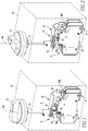
Fig. 1 is a perspective view of an improved rotary motion switching apparatus situated on a circuit interrupter and being disposed inside a NEMA box that is depicted in phantom lines, with the rotary motion switching apparatus being in a first position and with the circuit interrupter being in a first state; -
Fig. 2 is a view similar toFig. 1 , except depicting the rotary motion switching apparatus in a second position and depicting the circuit interrupter in a second state; -
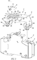
Fig. 3 is a view showing an improved assembly in accordance with the disclosed and claimed concept in which the rotary motion switching apparatus ofFig. 2 is exploded away from the circuit interrupter ofFig. 2 ; -
Fig. 4 is an exploded view of the rotary motion switching apparatus ofFig. 3 ; -
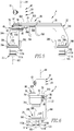
Fig. 5 is a front elevational view of the rotary motion switching apparatus; -
Fig. 6 is a side elevational view of the rotary motion switching apparatus; and -
Fig. 7 is a view of the rotary motion switching apparatus being mounted to a circuit interrupter from among a plurality of circuit interrupters that are ganged together. - Similar numerals refer to similar parts throughout the specification.
- An improved rotary
motion switching apparatus 4, which may be alternatively referred to herein as theapparatus 4, is depicted inFigs. 1-7 and is depicted in an exploded fashion inFig. 4 . Theapparatus 4 is usable in conjunction with acircuit interrupter 6 such as is depicted inFigs. 1-3 to form an assembly 8 that is likewise in accordance with the disclosed and claimed concept. Furthermore, theapparatus 4 is usable with a plurality of ganged circuit interrupters, such as are indicated at thenumeral 106 inFig. 7 . - As can be understood from
Figs. 1 and 2 , theapparatus 4 is usable in conjunction with the circuit interrupter 6 (or with multiple instances ofcircuit interrupters 106, such as are indicated inFig. 7 ) to form the assembly 8 when the assembly 8 is used inside aNEMA box 10 that is indicated inFigs. 1 and 2 in phantom lines. More specifically, the NEMAbox 10 includes ahandle 12 that is situated at an exterior of an enclosure of theNEMA box 10 and further includes ashaft 14 that is elongated, with one end of theshaft 14 being connected with thehandle 12, and with an opposite end of theshaft 14 being connected with theapparatus 4. Depending upon the dimensions of theNEMA box 10, theshaft 14 can be cut to an appropriate length such that its opposite ends extend between thehandle 12 and theapparatus 4. - As can be understood from
Figs. 1-3 , thecircuit interrupter 6 includes ahousing 16 that is molded from an appropriate resin material or other material and aswitch 18 that is movably situated on thehousing 16. Theswitch 18 in the depicted exemplary embodiment is movable between an ON position and an OFF/TRIPPED position to switch thecircuit interrupter 6 among a plurality of states in a well understood fashion. Thehousing 16 further includes a pair of openings formed therein that are indicated at thenumerals housing 16 in order enable tools such as screwdrivers and the like to be receivable therein and to be cooperable with terminals of thecircuit interrupter 6 that enable electrical connection between thecircuit interrupter 6 and load conductor wires and other wires, by way of example. - As can be understood from
Fig. 3 , theapparatus 4 is provided separately from thecircuit interrupter 6 and is mountable to thehousing 16 of thecircuit interrupter 6 by having portions thereof received in the openings 20. Since the openings 20 are pre-existing in thehousing 16 for the reception of tools therein in order to connect wires with terminals of thecircuit interrupter 6, theapparatus 4 advantageously is usable with thecircuit interrupter 6 without requiring any modification of thehousing 16 or of the mold that is used to form thehousing 16, which is highly advantageous from a cost standpoint. - As can be understood from
Figs. 1-6 , theapparatus 4 can be said to include abase 22, acrank apparatus 24 that is situated on thebase 22, and anattachment system 26 that is mounted on thebase 22 and which secures theapparatus 4 to thehousing 16. In the depicted exemplary embodiment, theattachment system 26 includes a pair of connectors that are indicated at thenumerals Figs. 1 and 2 , theapparatus 4 is mounted to and affixed to thecircuit interrupter 6. - As is best shown in
Fig. 4 , thebase 22 can be said to include amain plate 30 in which anelongated slot 32 is formed. Thebase 22 further includes a pair ofconnection plates main plate 30. Thebase 22 further includes a pair ofbase plates connection plates base 22 further includes a pair oftabs base plates base plates holes Fig. 4 , the base plates 36 are oriented substantially parallel with themain plate 30, and the connection plates 34 are oriented substantially perpendicular to themain plate 30 and the base plates 36. When theapparatus 4 is mounted to thecircuit interrupter 6 with the connectors 28 being fully received in the openings 20, the tabs 38 confrontingly engage therebetween a portion of thehousing 16 such that the portion of thehousing 16 is interposed between the tabs 38 to advantageously resist movement of thebase 22 with respect to thehousing 16 along a direction parallel with the longitudinal extent of theslot 32. As can be further understood fromFig. 4 , theconnectors holes - As can further be understood from
Fig. 4 , thecrank apparatus 24 includes acrank 42 which can be said to include aboss 44, acrank plate 46, and ascrew 48. Thescrew 48 engages an underside of thecrank plate 46 and fastens thecrank plate 46 to theboss 44. Thecrank 42 can be said to constitute afirst portion 42 of thecrank apparatus 24. - The
main plate 30 has anaperture 50 formed therein within which theboss 44 is receivable. When thecrank 42 is installed on thebase 22, ashoulder 52 of theboss 44 is receivable against anupper surface 51 of themain plate 30. Theboss 44 can be said to include atip 54 that is of a rectangular shape and which is receivable through aspring 56 and is receivable in arectangular hole 58 that is formed in thecrank plate 46. With thetip 54 received in such fashion in therectangular hole 58, thescrew 48 can be received in a threaded hole formed in thetip 54 in order to connect together theboss 44 and thecrank plate 46 in a condition installed on thebase 22. - As can further be understood from
Fig. 4 , theboss 44 can be said to have areceptacle 60 formed therein at an end thereof opposite thetip 54 and which is configured to receive therein the corresponding end of theshaft 14. Theboss 44 further includes aset screw 62 that is receivable in a hole in the side of theboss 44 and which is configured to be tightened in the hole and to compressively engage a flat surface of theshaft 14 in order to affix theshaft 14 and thecrank 42 together. - It can be seen that the
spring 56 includes a pair of legs that are indicated at thenumerals legs openings spring 56 to rotationally bias thecrank 42 in a desirable fashion that is tailored to the needs of the particular application. For instance, thespring 56 may rotationally bias thecrank apparatus 24 toward an OFF or TRIPPED state of thecircuit interrupter 6, by way of example and without limitation. - As can further be understood from
Fig. 4 , thecrank apparatus 24 further includes aslider 68 and alink 70 which together can be said to form a second portion of thecrank apparatus 24 that is cooperable with the first portion of thecrank apparatus 24, i.e., thecrank 42. Thelink 70 is pivotably connected with both theslider 68 and thecrank 42 via pinned connections therebetween, as will be set forth in greater detail below. More specifically, thelink 70 has formed therein a pair ofholes link 70 and each of thecrank 42 and theslider 68. - The
slider 68 can be said to include amain portion 74 having formed therein a pair ofholes slider 68 further includes a pair oflugs main portion 74 and that are cooperable with theswitch 18 to move it among its various positions. The lugs 76 are in a confronting relationship with one another. Theslider 68 further includes afastening plate 78 that has formed therein a pair ofholes slider 68 further includes a pair ofpins slot 32, and are receivable in the holes 84 and which are cooperable with a pair of lockingfasteners pin 82A is additionally received through thehole 72B in thelink 70 before being connected with the lockingfastener 86A. The lockingfastener 86A receives thepin 82A in a locking opening formed therein and is receivable against an underside of thelink 70 adjacent thehole 72B. In a like fashion, the lockingfastener 86B receives thepin 82B in a locking opening formed therein and is receivable against an underside of themain portion 74. In such a fashion, theslider 68 is mounted to thebase 22 and is slidably translatable along themain plate 30 via sliding movement of the pins 82 within theslot 32. Furthermore, thelink 70 is pivotably connected with theslider 68. - The
crank apparatus 24 further includes apin 88 that is receivable in thehole 72A in thelink 70 and that is further received through ahole 90 that is formed in thecrank plate 46. Thepin 88 is further received in a locking opening of a lockingfastener 92 that is receivable against an underside of thecrank plate 46 to provide the pivotable connection between thelink 70 and thecrank 42. - As can be understood from the accompanying figures, the
crank 42 is rotatable about an axis ofrotation 94 between a first orientation such as is depicted generally inFig. 1 and a second orientation such as is depicted generally inFig. 2 . The axis ofrotation 94 extends through therectangular hole 58 formed in thecrank plate 46 and further extends through theaperture 50 formed in themain plate 30. Thehole 90 in thecrank plate 46 is situated at alocation 96 that is spaced adistance 98 from the axis ofrotation 94. Since thelink 70 is pivotably connected between thecrank 42 and theslider 68, it can be understood that rotational movement of thecrank 42 about the axis ofrotation 94 is converted via thelink 70 being connected with thecrank 42 at thelocation 96 spaced thedistance 98 from the axis ofrotation 94 into translational movement of theslider 68 within theslot 32 along amovement axis 100 that is parallel with theslot 32. More specifically, and as can be understood fromFigs. 1 and 2 , when thecrank 42 is in its first orientation, such as is depicted inFig. 1 , theslider 68 is in a first position. In a like fashion, when thecrank 42 is in its second orientation, such as is depicted generally inFig. 2 , theslider 68 is in a second position. Since thecrank apparatus 24 transforms rotational movement of thehandle 12 and theshaft 14 applied to the crank 42 into translational movement of theslider 68 along themovement axis 100, it can be seen that such rotation of thehandle 12 causes the lugs 76 to engage theswitch 18 of thecircuit interrupter 6 and to move theswitch 18 among its various positions, which changes thecircuit interrupter 6 among its various states. - As is best shown in
Figs. 4-6 , the connectors 28 can be said to each include anelongated body 102 that is elongated along a direction ofelongation 105 and which has formed therein anelongated notch 107 that is elongated along the direction ofelongation 105. Each connector 28 further includes ahead 107 at one end thereof and a pair of latches that are situated thereon opposite thehead 109 and which are indicated at thenumerals latches notch 107 in a pair of directions that are indicated at thenumerals elongation 105 and are opposite one another. - The
latches engagement surface elongation 105. When the connectors 28 are fully received in the openings 20, the engagement surfaces 115 engage astructure 117 of the housing that is best shown inFig. 7 . In the depicted exemplary embodiment, thestructure 117 is an annular flange that is situated adjacent the opening 20 and that confrontingly engages the engagement surfaces 115 when the connectors 28 are received in the openings 20. Such engagement between the engagement surfaces 115 and a corresponding surface of thestructure 117 advantageously resists removal of the connectors 28 from the openings 20 and thus likewise resists removal of theapparatus 4 from thecircuit interrupter 6. In such a situation, the engagement surfaces 115 directly confront and engage a corresponding confronting surface of thestructure 117 and thus enable the connectors 28 to remain affixed to thehousing 16 within the openings 20. - It is noted that the direction of elongation 113 is substantially parallel with the axis of
rotation 94 such that any reaction of the rotation of thehandle 12 that is applied to the connectors 28 results in thebodies 102 compressively engaging thehousing 16 within the openings 20 rather than applying forces between the engagement surfaces 115 and thestructures 117. As such, any forces that may be applied to the connectors 28 as a result of application of a torque to thehandle 12 at most further engage thebodies 102 with thehousing 16 within the openings 20 without compromising the connection between the engagement surfaces 115 and thestructures 117. Furthermore, it is noted that the engagement of the tabs 38 with thehousing 16 resists the application of any meaningful torque to the connectors 28 due to rotation of thehandle 12. - It thus can be seen that the
apparatus 4 is affixable to thecircuit interrupter 6 by receiving the connectors 28 in the openings 20, which enables theapparatus 4 to be affixed to thecircuit interrupter 6 using the pre-existing openings 20 and without a need of modifying thehousing 16 or the tooling that is used to form thehousing 16. Theapparatus 4 converts rotary motion of thehandle 12 of theNEMA box 10 into translation of theslider 68 which is cooperable with theswitch 18 to move thecircuit interrupter 6 among its various states. This provides an advantageously workable solution at relatively low cost. - As noted above, and as can be seen in
Fig. 7 , therotary switching apparatus 4 is connectable with a plurality ofcircuit interrupters 106 that are ganged together, with four of thecircuit interrupters 106 being depicted inFig. 7 as being ganged together. Theapparatus 4 can be mounted to any one of thecircuit interrupters 106 in the fashion set forth above, namely be receiving the connectors 28 in the openings 20, in order to be cooperable with theswitch 18 of thatcircuit interrupter 106 to thereby effect simultaneous movement of all of thecircuit interrupters 106 among their various states. Depending upon limitations of thecircuit interrupters 106 themselves, it may be more desirable to mount theapparatus 4 to one of the two inboard-situatedcircuit interrupters 106, such as is shown inFig. 7 , rather than being affixed to one of the two outboard-situatedcircuit interrupters 106, although such position is not intended to be limiting and is provided merely as an example. - It thus can be seen that the
apparatus 4 is relatively simple and inexpensive to manufacture and does not require any modification of thehousings 16 in order to be affixable to thecircuit interrupter 6. The attachment of the connectors 28 in the openings 20 with theheads 109 being received against the baseplates 36 and with thebodies 102 being received through the holes 40 and into the openings 20 with the engagement surfaces 115 being engaged with corresponding confronting surfaces of thestructures 117 causes theapparatus 4 to be affixed to thecircuit interrupter 6. Such affixing of theapparatus 4 to thecircuit interrupter 6 employs the pre-existing openings 20 and thus avoids the need for a modification of thehousing 16 or a modification of the tooling that is used to make thehousing 16, which is cost advantageous. Other advantages will be apparent. - While specific embodiments of the disclosed concept have been described in detail, it will be appreciated by those skilled in the art that various modifications and alternatives to those details could be developed in light of the overall teachings of the disclosure. Accordingly, the particular arrangements disclosed are meant to be illustrative only and not limiting as to the scope of the disclosed concept which is to be given the full breadth of the claims appended and any and all equivalents thereof.
Claims (13)
- A rotary motion switching apparatus that is usable with a circuit interrupter, the circuit interrupter having a housing, a switch situated on the housing, and at least a first opening formed in the housing, the rotary motion switching apparatus comprising:a base;an attachment system situated on the base, the attachment system comprising at least a first connector that is elongated, the at least first connector being structured to be at least partially received in the at least a first opening and being further structured to engage the housing within the at least first opening to resist removal of the at least first connector from the at least first opening and to affix the base to the housing;a crank apparatus situated on the base, the crank apparatus comprising a first portion and a second portion, the first portion being pivotable about an axis of rotation between a first orientation and a second orientation, the first portion and the second portion being engaged with one another at a location spaced from the axis of rotation, at least a part of the second portion being translatable along a movement axis between a first position and a second position, the first portion being in the first orientation when the at least part of the second portion is in the first position, the first portion being in the second orientation when the at least part of the second portion is in the second position; andthe second portion having a number of lugs that are structured to engage the switch and to move the switch between a first state and a second state, the at least part of the second portion being structured to be in the first position when the switch is in the first state, the at least part of the second portion being structured to be in the second position when the switch is in the second state.
- The rotary motion switching apparatus of Claim 1 wherein the at least first connector comprises a body and a latch that are structured to be received in the at least first opening, the body being elongated along a direction of elongation, the latch protruding from the body and comprising an engagement surface that is oriented substantially perpendicular to the direction of elongation, the engagement surface being structured to engage a portion of the housing within the at least first opening to resist removal of the body from the at least first opening.
- The rotary motion switching apparatus of Claim 2 wherein the body has formed therein a notch that is elongated and that extends along the direction of elongation, the latch extending from the body in a direction away from the notch.
- The rotary motion switching apparatus of Claim 3 wherein the at least first connector comprises another latch that is structured to be received in the at least first opening, the another latch protruding from the body and comprising another engagement surface that is oriented substantially perpendicular to the direction of elongation, the another engagement surface being structured to engage the housing within the at least first opening to resist removal of the body from the at least first opening, the another latch extending from the body in another direction away from the notch.
- The rotary motion switching apparatus of Claim 4 wherein the direction and the another direction are generally away from one another.
- The rotary motion switching apparatus of Claim 1 wherein the at least first connector comprises a body that is elongated along a direction of elongation and that is structured to be received in the at least first opening, the direction of elongation being oriented substantially parallel with the axis of rotation.
- The rotary motion switching apparatus of Claim 1 wherein the first portion and the second portion are pivotably connected together at the location spaced from the axis of rotation.
- The rotary motion switching apparatus of Claim 1 wherein the first portion has a receptacle formed therein, the receptacle being structured to receive therein an end of a shaft that has a handle situated on another end thereof.
- The rotary motion switching apparatus of Claim 1 wherein the at least part of the second portion comprises a slider that is at least partially situated in a slot formed in the base.
- The rotary motion switching apparatus of Claim 9 wherein the second portion further comprises a link that is pivotably connected between the slider and the first portion.
- The rotary motion switching apparatus of Claim 1 wherein the circuit interrupter has a second opening formed in the housing, and wherein the attachment system further comprises a second connector that is elongated, the second connector being structured to be at least partially received in the second opening and being further structured to engage the housing within the second opening to resist removal of the second connector from the second opening and to further affix the base to the housing.
- The rotary motion switching apparatus of Claim 11 wherein the at least first connector has a first head and a first body, wherein second connector has a second head and a second body, and wherein the base has a first hole and a second hole formed therein, the first body being elongated and being structured to be received in the at least first opening, the first head being received against the base and the first body being at least partially received in the first hole when the first body is received in the at least first opening, the second body being elongated and being structured to be received in the second opening, the second head being received against the base and the second body being at least partially received in the second hole when the second body is received in the second opening.
- An assembly comprising the rotary motion switching apparatus of Claim 1, the assembly further comprising:a circuit interrupter, the circuit interrupter having a housing, a switch situated on the housing, and at least a first opening formed in the housing;the at least first connector being at least partially received in the at least a first opening and being engaged with the housing within the at least first opening to resist removal of the at least first connector from the at least first opening and to affix the base to the housing; andthe number of lugs being engaged with the switch to move the switch between the first state and the second state, the at least part of the second portion being in the first position when the switch is in the first state, the at least part of the second portion being in the second position when the switch is in the second state.
Applications Claiming Priority (3)
| Application Number | Priority Date | Filing Date | Title |
|---|---|---|---|
| US15/875,177 US10312037B1 (en) | 2018-01-19 | 2018-01-19 | Rotary motion switching apparatus usable with circuit interrupter |
| US15/972,414 US10319541B1 (en) | 2018-01-19 | 2018-05-07 | Rotary motion switching apparatus usable with circuit interrupter |
| US16/154,845 US10312046B1 (en) | 2018-01-19 | 2018-10-09 | Rotary motion switching apparatus usable with circuit interrupter |
Publications (2)
| Publication Number | Publication Date |
|---|---|
| EP3514819A1 true EP3514819A1 (en) | 2019-07-24 |
| EP3514819B1 EP3514819B1 (en) | 2026-05-06 |
Family
ID=65033458
Family Applications (1)
| Application Number | Title | Priority Date | Filing Date |
|---|---|---|---|
| EP19152003.0A Active EP3514819B1 (en) | 2018-01-19 | 2019-01-15 | Rotary motion switching apparatus usable with circuit interrupter |
Country Status (3)
| Country | Link |
|---|---|
| US (1) | US10312046B1 (en) |
| EP (1) | EP3514819B1 (en) |
| CA (1) | CA3029490C (en) |
Families Citing this family (3)
| Publication number | Priority date | Publication date | Assignee | Title |
|---|---|---|---|---|
| US11070140B2 (en) * | 2018-10-25 | 2021-07-20 | Eaton Intelligent Power Limited | Low inductance bus assembly and power converter apparatus including the same |
| EP3889983B1 (en) | 2020-04-01 | 2024-04-03 | Gorlan Team, S.L.U. | Detachable knob for actuating switchgear, and a switchgear device incorporating the detachable knob |
| CN221040865U (en) * | 2023-11-14 | 2024-05-28 | 施耐德电气(中国)有限公司 | Reset component for handle mechanism, handle mechanism and switch equipment |
Citations (1)
| Publication number | Priority date | Publication date | Assignee | Title |
|---|---|---|---|---|
| US5493084A (en) * | 1994-08-04 | 1996-02-20 | Eaton Corporation | Door release for circuit interrupter rotary handle mechanism |
Family Cites Families (9)
| Publication number | Priority date | Publication date | Assignee | Title |
|---|---|---|---|---|
| US3260808A (en) | 1961-09-15 | 1966-07-12 | Gen Electric | Electric switch with lockable rotary operator |
| US3324259A (en) | 1966-02-25 | 1967-06-06 | Ite Circuit Breaker Ltd | Variable depth rotary handle operator for circuit breakers |
| US5288958A (en) * | 1992-03-30 | 1994-02-22 | Westinghouse Electric Corp. | Lockable remote rotary handle operator for circuit breakers |
| DE19939717A1 (en) * | 1999-08-21 | 2001-02-22 | Moeller Gmbh | Manual operating device electrical switching device, has rotary handle connected to drive plate within ridge with edge segments forming circle when in off position |
| JP4058895B2 (en) | 2000-10-02 | 2008-03-12 | 富士電機機器制御株式会社 | Handle operating mechanism of circuit breaker |
| JP4186409B2 (en) * | 2000-10-30 | 2008-11-26 | 富士電機機器制御株式会社 | Circuit breaker |
| KR100512917B1 (en) * | 2003-12-19 | 2005-09-06 | 엘에스산전 주식회사 | Handle driving gear of motor protected breaker |
| US6969813B1 (en) | 2004-08-24 | 2005-11-29 | Siemens Energy & Automation, Inc. | Direct mount rotary handle operating mechanism which is suitable for isolation |
| JP4923907B2 (en) * | 2006-09-21 | 2012-04-25 | 富士電機機器制御株式会社 | External circuit handle device for circuit breaker |
-
2018
- 2018-10-09 US US16/154,845 patent/US10312046B1/en active Active
-
2019
- 2019-01-09 CA CA3029490A patent/CA3029490C/en active Active
- 2019-01-15 EP EP19152003.0A patent/EP3514819B1/en active Active
Patent Citations (1)
| Publication number | Priority date | Publication date | Assignee | Title |
|---|---|---|---|---|
| US5493084A (en) * | 1994-08-04 | 1996-02-20 | Eaton Corporation | Door release for circuit interrupter rotary handle mechanism |
Also Published As
| Publication number | Publication date |
|---|---|
| EP3514819B1 (en) | 2026-05-06 |
| CA3029490A1 (en) | 2019-07-19 |
| US10312046B1 (en) | 2019-06-04 |
| CA3029490C (en) | 2025-09-23 |
Similar Documents
| Publication | Publication Date | Title |
|---|---|---|
| US10312037B1 (en) | Rotary motion switching apparatus usable with circuit interrupter | |
| EP4167263B1 (en) | Switch, power conversion apparatus, and power supply system | |
| US7286340B2 (en) | Adjustable adapter for mounting electrical switching apparatus and enclosure assembly employing the same | |
| US7695313B2 (en) | Electrical enclosure, and panel assembly and mounting assembly therefor | |
| EP3514819A1 (en) | Rotary motion switching apparatus usable with circuit interrupter | |
| US7459650B2 (en) | Electrical switching apparatus, and latch assembly and latch engagement control mechanism therefor | |
| US10319541B1 (en) | Rotary motion switching apparatus usable with circuit interrupter | |
| CA2629502A1 (en) | Electrical switching apparatus, and latch assembly and latch engagement control mechanism therefor | |
| MX2007012516A (en) | Electrical enclosure and interior assembly therefor. | |
| US6720496B1 (en) | Electrical box for supporting various types of fixtures | |
| US4262181A (en) | Snap-in switch housing | |
| US6642463B1 (en) | Circuit breaker remote actuator with fulcrum member to assist assembly and associated method | |
| US20050162243A1 (en) | Electrical switching apparatus interface assembly and operating handle attachment therefor | |
| US9299523B1 (en) | Switching device assembly and adapter assembly therefor | |
| CN105359244B (en) | Concealed/Sliding Door System for Field Installed Accessory Entry | |
| US20040032702A1 (en) | Adapter mechanism for use with a circuit breaker | |
| US7319373B2 (en) | Electrical switching apparatus and terminal housing therefor | |
| WO2020074121A1 (en) | Rotary motion switching apparatus usable with circuit interrupter | |
| EP2302656B1 (en) | Electrical switching apparatus and shaft assembly therefor | |
| US20200027670A1 (en) | Electrical switching apparatus and transfer assembly therefor | |
| US7420132B2 (en) | Busway plug fitting containing an operating mechanism with a reverse link | |
| CA2619705A1 (en) | Electrical switching device | |
| CN220138146U (en) | Electrical switching device | |
| CN223245445U (en) | Shell with buckle on integral flange | |
| CA2580037C (en) | Auxiliary switch sub-assembly and electrical switching apparatus employing the same |
Legal Events
| Date | Code | Title | Description |
|---|---|---|---|
| PUAI | Public reference made under article 153(3) epc to a published international application that has entered the european phase |
Free format text: ORIGINAL CODE: 0009012 |
|
| STAA | Information on the status of an ep patent application or granted ep patent |
Free format text: STATUS: REQUEST FOR EXAMINATION WAS MADE |
|
| 17P | Request for examination filed |
Effective date: 20190115 |
|
| AK | Designated contracting states |
Kind code of ref document: A1 Designated state(s): AL AT BE BG CH CY CZ DE DK EE ES FI FR GB GR HR HU IE IS IT LI LT LU LV MC MK MT NL NO PL PT RO RS SE SI SK SM TR |
|
| AX | Request for extension of the european patent |
Extension state: BA ME |
|
| STAA | Information on the status of an ep patent application or granted ep patent |
Free format text: STATUS: EXAMINATION IS IN PROGRESS |
|
| 17Q | First examination report despatched |
Effective date: 20211122 |
|
| P01 | Opt-out of the competence of the unified patent court (upc) registered |
Effective date: 20230521 |
|
| GRAP | Despatch of communication of intention to grant a patent |
Free format text: ORIGINAL CODE: EPIDOSNIGR1 |
|
| STAA | Information on the status of an ep patent application or granted ep patent |
Free format text: STATUS: GRANT OF PATENT IS INTENDED |
|
| INTG | Intention to grant announced |
Effective date: 20260213 |
|
| GRAS | Grant fee paid |
Free format text: ORIGINAL CODE: EPIDOSNIGR3 |
|
| GRAA | (expected) grant |
Free format text: ORIGINAL CODE: 0009210 |
|
| STAA | Information on the status of an ep patent application or granted ep patent |
Free format text: STATUS: THE PATENT HAS BEEN GRANTED |