EP3514804A1 - Cable - Google Patents
Cable Download PDFInfo
- Publication number
- EP3514804A1 EP3514804A1 EP19152246.5A EP19152246A EP3514804A1 EP 3514804 A1 EP3514804 A1 EP 3514804A1 EP 19152246 A EP19152246 A EP 19152246A EP 3514804 A1 EP3514804 A1 EP 3514804A1
- Authority
- EP
- European Patent Office
- Prior art keywords
- conductor
- cable
- hollow tubes
- protective member
- hollow
- Prior art date
- Legal status (The legal status is an assumption and is not a legal conclusion. Google has not performed a legal analysis and makes no representation as to the accuracy of the status listed.)
- Granted
Links
Images




Classifications
-
- B—PERFORMING OPERATIONS; TRANSPORTING
- B23—MACHINE TOOLS; METAL-WORKING NOT OTHERWISE PROVIDED FOR
- B23H—WORKING OF METAL BY THE ACTION OF A HIGH CONCENTRATION OF ELECTRIC CURRENT ON A WORKPIECE USING AN ELECTRODE WHICH TAKES THE PLACE OF A TOOL; SUCH WORKING COMBINED WITH OTHER FORMS OF WORKING OF METAL
- B23H7/00—Processes or apparatus applicable to both electrical discharge machining and electrochemical machining
- B23H7/02—Wire-cutting
- B23H7/04—Apparatus for supplying current to working gap; Electric circuits specially adapted therefor
-
- H—ELECTRICITY
- H01—ELECTRIC ELEMENTS
- H01B—CABLES; CONDUCTORS; INSULATORS; SELECTION OF MATERIALS FOR THEIR CONDUCTIVE, INSULATING OR DIELECTRIC PROPERTIES
- H01B7/00—Insulated conductors or cables characterised by their form
- H01B7/30—Insulated conductors or cables characterised by their form with arrangements for reducing conductor losses when carrying alternating current, e.g. due to skin effect
-
- B—PERFORMING OPERATIONS; TRANSPORTING
- B23—MACHINE TOOLS; METAL-WORKING NOT OTHERWISE PROVIDED FOR
- B23H—WORKING OF METAL BY THE ACTION OF A HIGH CONCENTRATION OF ELECTRIC CURRENT ON A WORKPIECE USING AN ELECTRODE WHICH TAKES THE PLACE OF A TOOL; SUCH WORKING COMBINED WITH OTHER FORMS OF WORKING OF METAL
- B23H1/00—Electrical discharge machining, i.e. removing metal with a series of rapidly recurring electrical discharges between an electrode and a workpiece in the presence of a fluid dielectric
- B23H1/02—Electric circuits specially adapted therefor, e.g. power supply, control, preventing short circuits or other abnormal discharges
-
- B—PERFORMING OPERATIONS; TRANSPORTING
- B23—MACHINE TOOLS; METAL-WORKING NOT OTHERWISE PROVIDED FOR
- B23H—WORKING OF METAL BY THE ACTION OF A HIGH CONCENTRATION OF ELECTRIC CURRENT ON A WORKPIECE USING AN ELECTRODE WHICH TAKES THE PLACE OF A TOOL; SUCH WORKING COMBINED WITH OTHER FORMS OF WORKING OF METAL
- B23H11/00—Auxiliary apparatus or details, not otherwise provided for
- B23H11/006—Electrical contacts or wires
-
- B—PERFORMING OPERATIONS; TRANSPORTING
- B23—MACHINE TOOLS; METAL-WORKING NOT OTHERWISE PROVIDED FOR
- B23H—WORKING OF METAL BY THE ACTION OF A HIGH CONCENTRATION OF ELECTRIC CURRENT ON A WORKPIECE USING AN ELECTRODE WHICH TAKES THE PLACE OF A TOOL; SUCH WORKING COMBINED WITH OTHER FORMS OF WORKING OF METAL
- B23H7/00—Processes or apparatus applicable to both electrical discharge machining and electrochemical machining
- B23H7/02—Wire-cutting
- B23H7/08—Wire electrodes
-
- H—ELECTRICITY
- H01—ELECTRIC ELEMENTS
- H01B—CABLES; CONDUCTORS; INSULATORS; SELECTION OF MATERIALS FOR THEIR CONDUCTIVE, INSULATING OR DIELECTRIC PROPERTIES
- H01B11/00—Communication cables or conductors
-
- H—ELECTRICITY
- H01—ELECTRIC ELEMENTS
- H01B—CABLES; CONDUCTORS; INSULATORS; SELECTION OF MATERIALS FOR THEIR CONDUCTIVE, INSULATING OR DIELECTRIC PROPERTIES
- H01B5/00—Non-insulated conductors or conductive bodies characterised by their form
- H01B5/08—Several wires or the like stranded in the form of a rope
-
- H—ELECTRICITY
- H01—ELECTRIC ELEMENTS
- H01B—CABLES; CONDUCTORS; INSULATORS; SELECTION OF MATERIALS FOR THEIR CONDUCTIVE, INSULATING OR DIELECTRIC PROPERTIES
- H01B7/00—Insulated conductors or cables characterised by their form
- H01B7/02—Disposition of insulation
-
- H—ELECTRICITY
- H01—ELECTRIC ELEMENTS
- H01B—CABLES; CONDUCTORS; INSULATORS; SELECTION OF MATERIALS FOR THEIR CONDUCTIVE, INSULATING OR DIELECTRIC PROPERTIES
- H01B7/00—Insulated conductors or cables characterised by their form
- H01B7/02—Disposition of insulation
- H01B7/0233—Cables with a predominant gas dielectric
-
- H—ELECTRICITY
- H01—ELECTRIC ELEMENTS
- H01B—CABLES; CONDUCTORS; INSULATORS; SELECTION OF MATERIALS FOR THEIR CONDUCTIVE, INSULATING OR DIELECTRIC PROPERTIES
- H01B7/00—Insulated conductors or cables characterised by their form
- H01B7/17—Protection against damage caused by external factors, e.g. sheaths or armouring
-
- H—ELECTRICITY
- H01—ELECTRIC ELEMENTS
- H01B—CABLES; CONDUCTORS; INSULATORS; SELECTION OF MATERIALS FOR THEIR CONDUCTIVE, INSULATING OR DIELECTRIC PROPERTIES
- H01B7/00—Insulated conductors or cables characterised by their form
- H01B7/17—Protection against damage caused by external factors, e.g. sheaths or armouring
- H01B7/18—Protection against damage caused by wear, mechanical force or pressure; Sheaths; Armouring
- H01B7/185—Sheaths comprising internal cavities or channels
-
- H—ELECTRICITY
- H01—ELECTRIC ELEMENTS
- H01B—CABLES; CONDUCTORS; INSULATORS; SELECTION OF MATERIALS FOR THEIR CONDUCTIVE, INSULATING OR DIELECTRIC PROPERTIES
- H01B9/00—Power cables
-
- B—PERFORMING OPERATIONS; TRANSPORTING
- B23—MACHINE TOOLS; METAL-WORKING NOT OTHERWISE PROVIDED FOR
- B23H—WORKING OF METAL BY THE ACTION OF A HIGH CONCENTRATION OF ELECTRIC CURRENT ON A WORKPIECE USING AN ELECTRODE WHICH TAKES THE PLACE OF A TOOL; SUCH WORKING COMBINED WITH OTHER FORMS OF WORKING OF METAL
- B23H1/00—Electrical discharge machining, i.e. removing metal with a series of rapidly recurring electrical discharges between an electrode and a workpiece in the presence of a fluid dielectric
-
- H—ELECTRICITY
- H01—ELECTRIC ELEMENTS
- H01B—CABLES; CONDUCTORS; INSULATORS; SELECTION OF MATERIALS FOR THEIR CONDUCTIVE, INSULATING OR DIELECTRIC PROPERTIES
- H01B11/00—Communication cables or conductors
- H01B11/18—Coaxial cables; Analogous cables having more than one inner conductor within a common outer conductor
- H01B11/1834—Construction of the insulation between the conductors
- H01B11/1843—Construction of the insulation between the conductors of tubular structure
-
- H—ELECTRICITY
- H01—ELECTRIC ELEMENTS
- H01B—CABLES; CONDUCTORS; INSULATORS; SELECTION OF MATERIALS FOR THEIR CONDUCTIVE, INSULATING OR DIELECTRIC PROPERTIES
- H01B11/00—Communication cables or conductors
- H01B11/18—Coaxial cables; Analogous cables having more than one inner conductor within a common outer conductor
- H01B11/1834—Construction of the insulation between the conductors
- H01B11/1847—Construction of the insulation between the conductors of helical wrapped structure
-
- H—ELECTRICITY
- H01—ELECTRIC ELEMENTS
- H01B—CABLES; CONDUCTORS; INSULATORS; SELECTION OF MATERIALS FOR THEIR CONDUCTIVE, INSULATING OR DIELECTRIC PROPERTIES
- H01B7/00—Insulated conductors or cables characterised by their form
- H01B7/17—Protection against damage caused by external factors, e.g. sheaths or armouring
- H01B7/28—Protection against damage caused by moisture, corrosion, chemical attack or weather
Definitions
- a wire electrical discharge machine which includes a work pan in which a dielectric working fluid is stored, a table which is provided in the work pan and on which a workpiece is placed, and a voltage application device for applying a voltage between a wire and the table (refer to Japanese Laid-Open Patent Publication No. 2006-281395 ).
- the cable for application of voltage may be immersed in the working fluid.
- the conductor of the cable and the table at the ground potential are electrostatically coupled through the working fluid and then leakage of electricity from the cable is likely to occur.
- alternating current (AC) voltage is applied so as to avoid corrosion of the workpiece.
- the frequency is increased even up to several megahertz, as the surface roughness after processed in the finishing work becomes finer. As the frequency becomes higher, the influence of leakage due to electrostatic coupling becomes worse, and the peak value of the AC machining voltage becomes smaller as the surface area of the cable in contact with the working fluid becomes larger, resulting in unstable discharge.
- a member with a low relative permittivity be provided around the conductor so as to suppress leakage from the cable.
- fluororesin having a generally low permittivity, for example, is employed as the low relative permittivity member, there is a concern that it will be difficult to reduce the capacitance occurring between the conductor and working fluid to such an extent that the leakage from the cable can be practically suppressed.
- an object of the present invention is to provide a cable capable of considerably reducing capacitance occurring with a conductor.
- a cable according to an aspect of the present invention includes: a linear conductor; a plurality of hollow tubes made of resin and which are disposed around the conductor so that an air layer is formed around the conductor, the hollow tubes extending in a longitudinal direction of the conductor; and an insulating protective member configured to protect the conductor and the plurality of hollow tubes.
- the plurality of hollow tubes form an air layer around the conductor, and therefore the capacitance occurring between the conductor and the working fluid is considerably reduced.
- FIG. 1 is a schematic diagram showing a cross section of a cable 10 of an embodiment.
- FIG. 1 shows a cross section of the cable 10 taken along a direction orthogonal to its longitudinal direction.
- the cable 10 of this embodiment is employed as a feeding cable for applying voltage to a wire of a wire electrical discharge machine, or as a signal cable for measuring voltage applied to a wire of a wire electrical discharge machine.
- the cable 10 is placed in the interior of a work pan.
- the cable 10 mainly includes a conductor 12, a protective member 14, and a plurality of hollow tubes 16.
- the conductor 12 is a transmission path on which voltage or signal is transmitted, and the conductor 12 is in the form of a line (a linear form).
- the external shape of the cross section of the conductor 12 in the direction orthogonal to the longitudinal direction is circular in FIG. 1 , but it can be other shape.
- the protective member 14 is an insulating member for protecting the conductor 12 and the plurality of hollow tubes 16.
- the protective member 14 has a tubular form, and is disposed so as to surround the plurality of hollow tubes 16.
- Examples of material for making the protective member 14 include rubber, resin, etc., for example.
- the plurality of hollow tubes 16 are tubes made of resin and which are arranged around the conductor 12 such that an air layer is formed around the conductor 12, and the plurality of hollow tubes 16 linearly extend along the longitudinal direction of the conductor 12.
- resin for making the hollow tubes 16 include silicone resin chiefly containing silicon, for example.
- the air layer formed around the conductor 12 by the plurality of hollow tubes 16 includes the interiors of the hollow tubes 16 and gaps outside the hollow tubes 16.
- each hollow tube 16 is in contact with the outer circumferential surface of the conductor 12 and the inner circumferential surface of the tubular protective member 14, and adjacent ones of the plurality of hollow tubes 16 are in contact with each other.
- the gaps outside the hollow tubes 16 include the portions surrounded by the outer circumferential surfaces of the hollow tubes 16 and the outer circumferential surface of the conductor 12 and the portions surrounded by the outer circumferential surfaces of the hollow tubes 16 and the inner circumferential surface of the tubular protective member 14.
- the outer peripheral shape and the inner peripheral shape of the hollow tubes 16 are substantially circular, and the plurality of hollow tubes 16 have substantially the same outer diameter and inner diameter. Also, in the cross section of the cable 10 taken along the direction orthogonal to the longitudinal direction, the center position of the circle C passing through the center positions of the respective hollow tubes 16 substantially coincides with the center position P of the conductor 12.
- the cable 10 of this embodiment includes the plurality of hollow tubes 16, and the hollow tubes 16 form an air layer around the conductor 12. Accordingly, even when the cable 10 is immersed in a dielectric working fluid stored in a work pan of a wire electrical discharge machine, the capacitance occurring between the working fluid and the conductor 12 can be considerably reduced. As a result, the cable 10 becomes less likely to leak electricity through the working fluid.
- adjacent ones of the plurality of hollow tubes 16 are in contact with each other, so that the tubular protective member 14 is prevented from coming in contact with the conductor 12 even when the cable 10 is pressed.
- the capacitance occurring between the working fluid and the conductor 12 can be considerably reduced.
- the hollow tubes 16 have a substantially circular outer peripheral shape and inner peripheral shape in the cross section taken along the direction orthogonal to the longitudinal direction of the cable 10.
- at least one of the outer peripheral shape and the inner peripheral shape may be other shape than a circle.
- the plurality of hollow tubes 16 have substantially the same outer diameter and inner diameter in the cross section taken along the direction orthogonal to the longitudinal direction of the cable 10. However, all of the plurality of hollow tubes 16 may have different outer diameters, or some of the plurality of hollow tubes 16 may have a different outer diameter from others. In the same way, all of the plurality of hollow tubes 16 may have different inner diameters, or some of the plurality of hollow tubes 16 may have a different inner diameter from others.
- adjacent ones of the plurality of hollow tubes 16 disposed around the conductor 12 are in contact with each other.
- the plurality of hollow tubes 16 may be spaced at intervals around the conductor 12.
- adjacent ones of the plurality of hollow tubes 16 are in contact with each other.
- hollow tubes 16 linearly extend along the longitudinal direction of the conductor 12.
- hollow tubes 16 may helically extend along the outer periphery of the conductor 12. This makes it easier to suppress relative positional shift of the hollow tubes 16 even when the cable 10 is bent.
- FIG. 2 only shows a single hollow tube 16 and omits the protective member 14.
- one end 16a of the ends 16a, 16b of the hollow tube 16 in the longitudinal direction may be closed. Closing one end 16a prevents the working fluid stored in the work pan from getting into the hollow tube 16 even when a portion of the cable 10 corresponding to the closed one end is placed inside the work pan of a wire electrical discharge machine. That is, it is preferable that, as one end 16a of the hollow tube 16, the end 16a on the side placed inside the work pan of the wire electrical discharge machine be closed. The other end 16b of the hollow tube 16 on the opposite side to the one end 16a may be closed.
- air may be supplied to the hollow tube 16 from an air supplier 20. Then, even when the working fluid gets into the hollow tube 16, the working fluid can be discharged out of the tube. Air from the air supplier 20 may be supplied to all of the plurality of hollow tubes 16. Alternatively, when a plurality of hollow tubes 16 communicate with each other, air may be supplied from the air supplier 20 only to some of the plurality of hollow tubes 16.
- the outer periphery of the conductor 12 is not coated.
- the conductor 12 may be provided with a coating member 30 made of resin and coating (covering) its outer periphery. This lengthens the distance between the conductor 12 and the protective member 14 as compared to cases where the coating member 30 is absent. This further reduces the capacitance occurring between the working fluid and the conductor 12.
- the conductor 12 has a form of a single line.
- the conductor 12 may be formed by twisting together bundles 12b of a plurality of strands 12a into a rope shape. Then, gaps are formed between the bundles 12b on the outer circumferential side of the conductor 12, and accordingly the proportion of gap inside the tubular protective member 14 is enlarged as compared to cases where the conductor 12 is in the form of a single line. This further reduces the capacitance occurring with the conductor 12.
- the plurality of strands 12a may be arranged in parallel, or may be twisted together.
- each bundle 12b may be individually coated (covered) with a coating member 30. As in the case described above, this also lengthens the distance between the conductor 12 and the protective member 14 as compared to cases where the coating members 30 are absent. This makes it possible to further reduce the capacitance occurring between the working fluid and the conductor 12.
- the cable 10 is a cable which has the single conductor 12.
- the cable 10 may be a coaxial cable which includes the conductor 12 located on the inside of the plurality of hollow tubes 16 and a tubular second conductor 40 located on the outside of the plurality of hollow tubes 16.
- the second conductor 40 is disposed inside the tubular protective member 14, and the conductor 12 and the plurality of hollow tubes 16 are inserted therein.
- the conductor 12 is connected to a wire electrode of a wire electrical discharge machine
- the second conductor 40 is connected to a table in the work pan of the wire electrical discharge machine.
- the table is a table on which a workpiece is placed.
- the conductor 12 is connected to the table, the second conductor 40 is connected to the wire electrode.
- the plurality of hollow tubes 16 reduce the capacitance between the conductor 12 and the second conductor 40.
- the protective member 14 is a tubular member that surrounds the plurality of hollow tubes 16.
- the protective member 14 may surround the conductor 12 and the plurality of hollow tubes 16 without leaving any gap.
- the air layer formed around the conductor 12 by the plurality of hollow tubes 16 is formed only inside the hollow tubes 16. As in the case of the above-described embodiment, this also further reduces the capacitance occurring between the working fluid and the conductor 12.
- the cable 10 is placed inside a work pan of a wire electrical discharge machine, but the cable 10 may be disposed inside or outside other equipment. That is to say, the cable may be employed as a feeding cable for applying voltage to other equipment than a wire electrical discharge machine, or as a signal cable for sending and receiving signals to and from other equipment.
- the cable (10) includes a linear conductor (12); a plurality of hollow tubes (16) made of resin and which are disposed around the conductor (12) such that an air layer is formed around the conductor (12), the hollow tubes extending in a longitudinal direction of the conductor (12); and an insulating protective member (14) configured to protect the conductor (12) and the plurality of hollow tubes (16).
- the plurality of hollow tubes (16) form an air layer around the conductor (12), and it is therefore possible to considerably reduce the capacitance occurring with the conductor (12).
- Adjacent ones of the plurality of hollow tubes (16) may be in contact with each other. This makes it possible to prevent the protective member (14) from coming into contact with the conductor (12) even when the cable (10) is pressed. Thus, even when the cable (10) is kept in a pressed state, the capacitance occurring with the conductor (12) can be considerably reduced.
- the hollow tubes (16) may helically extend along an outer peripheral surface of the conductor (12). This makes it easy to suppress relative positional shift of the hollow tubes (16) even when the cable (10) is bent.
- At least one end (16a) of the hollow tubes (16) may be closed.
- Air may be supplied into the hollow tubes (16). With this structure, even when working fluid gets into the hollow tubes (16), the working fluid can be discharged out of the tubes.
- the cable (10) may further include a resin coating member (30) configured to cover an outer peripheral surface of the conductor (12). Then, the distance between the conductor (12) and the protective member (14) is lengthened as compared to cases where the coating member (30) is absent. This further reduces the capacitance occurring with the conductor (12).
- the conductor (12) may be formed by twisting together bundles (12b) of a plurality of strands (12a) into a rope shape. With this structure, gaps are formed between the bundles (12b) on the outer peripheral side of the conductor (12), and accordingly the proportion of gap inside the protective member (14) is enlarged as compared to cases where the conductor (12) is in the form of a single line. This further reduces the capacitance occurring with the conductor (12).
- Each of the bundles (12b) may be coated with a coating member (30). Then, the distance between the conductor (12) and the protective member (14) is lengthened as compared to cases where the coating member (30) is absent. This further reduces the capacitance occurring with the conductor (12).
- the cable (10) may further include a tubular second conductor (40) which is disposed on an inside of the protective member (14) and in which the conductor (12) and the plurality of hollow tubes (16) are inserted. With this structure, the capacitance between the conductor (12) and the second conductor (40) is reduced by the plurality of hollow tubes (16).
- the protective member (14) may surround the conductor (12) and the plurality of hollow tubes (16) without leaving a gap, or may be a tubular member surrounding the plurality of hollow tubes (16).
- the cable (10) may be placed in an interior of a work pan of a wire electrical discharge machine.
Landscapes
- Engineering & Computer Science (AREA)
- Mechanical Engineering (AREA)
- Chemical & Material Sciences (AREA)
- Chemical Kinetics & Catalysis (AREA)
- Electrochemistry (AREA)
- Insulated Conductors (AREA)
- Electrical Discharge Machining, Electrochemical Machining, And Combined Machining (AREA)
Abstract
Description
- The present invention relates to a cable employed for a wire electrical discharge machine, for example. Description of the Related Art:
A wire electrical discharge machine is disclosed which includes a work pan in which a dielectric working fluid is stored, a table which is provided in the work pan and on which a workpiece is placed, and a voltage application device for applying a voltage between a wire and the table (refer to Japanese Laid-Open Patent Publication No.2006-281395 - In the wire electrical discharge machine described in Japanese Laid-Open Patent Publication No.
2006-281395 - It may be suggested that a member with a low relative permittivity be provided around the conductor so as to suppress leakage from the cable. However, even when fluororesin, having a generally low permittivity, for example, is employed as the low relative permittivity member, there is a concern that it will be difficult to reduce the capacitance occurring between the conductor and working fluid to such an extent that the leakage from the cable can be practically suppressed.
- Accordingly, an object of the present invention is to provide a cable capable of considerably reducing capacitance occurring with a conductor.
- A cable according to an aspect of the present invention includes: a linear conductor; a plurality of hollow tubes made of resin and which are disposed around the conductor so that an air layer is formed around the conductor, the hollow tubes extending in a longitudinal direction of the conductor; and an insulating protective member configured to protect the conductor and the plurality of hollow tubes.
- According to the cable of the aspect above, the plurality of hollow tubes form an air layer around the conductor, and therefore the capacitance occurring between the conductor and the working fluid is considerably reduced.
- The above and other objects, features, and advantages of the present invention will become more apparent from the following description when taken in conjunction with the accompanying drawings, in which a preferred embodiment of the present invention is shown by way of illustrative example.
-
-
FIG. 1 is a schematic diagram showing a cross section of a cable according to an embodiment; -
FIG. 2 is a schematicdiagram showing Modification 1 of the cable; -
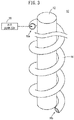
FIG. 3 is a schematic diagram showing Modification 2 of the cable; -
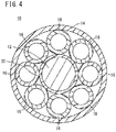
FIG. 4 is a schematic diagram showing a cross section of Modification 3 of the cable; -
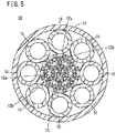
FIG. 5 is a schematic diagram showing a cross section of Modification 4 of the cable; -
FIG. 6 is a schematic diagram showing a cross section of Modification 5 of the cable; -
FIG. 7 is a schematic diagram showing a cross section of Modification 6 of the cable; and -
FIG. 8 is a schematic diagram showing a cross section of Modification 7 of the cable. - The cable of the present invention will be described in detail below in conjunction with preferred embodiments while referring to the accompanying drawings.
-
FIG. 1 is a schematic diagram showing a cross section of acable 10 of an embodiment.FIG. 1 shows a cross section of thecable 10 taken along a direction orthogonal to its longitudinal direction. Thecable 10 of this embodiment is employed as a feeding cable for applying voltage to a wire of a wire electrical discharge machine, or as a signal cable for measuring voltage applied to a wire of a wire electrical discharge machine. Thecable 10 is placed in the interior of a work pan. Thecable 10 mainly includes aconductor 12, aprotective member 14, and a plurality ofhollow tubes 16. - The
conductor 12 is a transmission path on which voltage or signal is transmitted, and theconductor 12 is in the form of a line (a linear form). The external shape of the cross section of theconductor 12 in the direction orthogonal to the longitudinal direction is circular inFIG. 1 , but it can be other shape. - The
protective member 14 is an insulating member for protecting theconductor 12 and the plurality ofhollow tubes 16. In this embodiment, theprotective member 14 has a tubular form, and is disposed so as to surround the plurality ofhollow tubes 16. Examples of material for making theprotective member 14 include rubber, resin, etc., for example. - The plurality of
hollow tubes 16 are tubes made of resin and which are arranged around theconductor 12 such that an air layer is formed around theconductor 12, and the plurality ofhollow tubes 16 linearly extend along the longitudinal direction of theconductor 12. Examples of resin for making thehollow tubes 16 include silicone resin chiefly containing silicon, for example. - In this embodiment, the air layer formed around the
conductor 12 by the plurality ofhollow tubes 16 includes the interiors of thehollow tubes 16 and gaps outside thehollow tubes 16. In this embodiment, eachhollow tube 16 is in contact with the outer circumferential surface of theconductor 12 and the inner circumferential surface of the tubularprotective member 14, and adjacent ones of the plurality ofhollow tubes 16 are in contact with each other. Accordingly, the gaps outside thehollow tubes 16 include the portions surrounded by the outer circumferential surfaces of thehollow tubes 16 and the outer circumferential surface of theconductor 12 and the portions surrounded by the outer circumferential surfaces of thehollow tubes 16 and the inner circumferential surface of the tubularprotective member 14. - In the cross section of the
cable 10 taken along the direction orthogonal to the longitudinal direction, the outer peripheral shape and the inner peripheral shape of thehollow tubes 16 are substantially circular, and the plurality ofhollow tubes 16 have substantially the same outer diameter and inner diameter. Also, in the cross section of thecable 10 taken along the direction orthogonal to the longitudinal direction, the center position of the circle C passing through the center positions of the respectivehollow tubes 16 substantially coincides with the center position P of theconductor 12. - As described above, the
cable 10 of this embodiment includes the plurality ofhollow tubes 16, and thehollow tubes 16 form an air layer around theconductor 12. Accordingly, even when thecable 10 is immersed in a dielectric working fluid stored in a work pan of a wire electrical discharge machine, the capacitance occurring between the working fluid and theconductor 12 can be considerably reduced. As a result, thecable 10 becomes less likely to leak electricity through the working fluid. - Furthermore, adjacent ones of the plurality of
hollow tubes 16 are in contact with each other, so that the tubularprotective member 14 is prevented from coming in contact with theconductor 12 even when thecable 10 is pressed. Thus, even when thecable 10 is immersed in the working fluid in a pressed state, the capacitance occurring between the working fluid and theconductor 12 can be considerably reduced. - The above embodiment has been described as an example of the present invention, but the technical scope of the present invention is not limited to the scope described in the embodiment above. Various modifications and improvements can of course be applied to the above-described embodiment. It is clear from the description of claims that embodiments modified or improved in various ways are included in the technical scope of the present invention.
- Some of modified or improved embodiments will be described below as modifications. Constituent elements that are equivalent to those described in the embodiment above will be labeled using the same reference numerals, and overlapping descriptions thereof will not be repeated.
- In the above-described embodiment, the
hollow tubes 16 have a substantially circular outer peripheral shape and inner peripheral shape in the cross section taken along the direction orthogonal to the longitudinal direction of thecable 10. However, at least one of the outer peripheral shape and the inner peripheral shape may be other shape than a circle. - Further, in the above-described embodiment, the plurality of
hollow tubes 16 have substantially the same outer diameter and inner diameter in the cross section taken along the direction orthogonal to the longitudinal direction of thecable 10. However, all of the plurality ofhollow tubes 16 may have different outer diameters, or some of the plurality ofhollow tubes 16 may have a different outer diameter from others. In the same way, all of the plurality ofhollow tubes 16 may have different inner diameters, or some of the plurality ofhollow tubes 16 may have a different inner diameter from others. - In the above-described embodiment, adjacent ones of the plurality of
hollow tubes 16 disposed around theconductor 12 are in contact with each other. However, the plurality ofhollow tubes 16 may be spaced at intervals around theconductor 12. However, as mentioned above, for the purpose of preventing the tubularprotective member 14 from coming in contact with theconductor 12 even when thecable 10 is pressed, it is preferred that adjacent ones of the plurality ofhollow tubes 16 are in contact with each other. - In the above-described embodiment, the
hollow tubes 16 linearly extend along the longitudinal direction of theconductor 12. However, as shown inFIG. 2 ,hollow tubes 16 may helically extend along the outer periphery of theconductor 12. This makes it easier to suppress relative positional shift of thehollow tubes 16 even when thecable 10 is bent. In order to facilitate understanding,FIG. 2 only shows a singlehollow tube 16 and omits theprotective member 14. - Further, as shown also in
FIG. 2 , oneend 16a of theends hollow tube 16 in the longitudinal direction may be closed. Closing oneend 16a prevents the working fluid stored in the work pan from getting into thehollow tube 16 even when a portion of thecable 10 corresponding to the closed one end is placed inside the work pan of a wire electrical discharge machine. That is, it is preferable that, as oneend 16a of thehollow tube 16, theend 16a on the side placed inside the work pan of the wire electrical discharge machine be closed. Theother end 16b of thehollow tube 16 on the opposite side to the oneend 16a may be closed. - Further, as shown in
FIG. 3 , when the oneend 16a and theother end 16b of thehollow tube 16 are both opened without being closed, then air may be supplied to thehollow tube 16 from anair supplier 20. Then, even when the working fluid gets into thehollow tube 16, the working fluid can be discharged out of the tube. Air from theair supplier 20 may be supplied to all of the plurality ofhollow tubes 16. Alternatively, when a plurality ofhollow tubes 16 communicate with each other, air may be supplied from theair supplier 20 only to some of the plurality ofhollow tubes 16. - In the above-described embodiment, the outer periphery of the
conductor 12 is not coated. However, as shown inFIG. 4 , theconductor 12 may be provided with acoating member 30 made of resin and coating (covering) its outer periphery. This lengthens the distance between theconductor 12 and theprotective member 14 as compared to cases where thecoating member 30 is absent. This further reduces the capacitance occurring between the working fluid and theconductor 12. - In the above-described embodiment, the
conductor 12 has a form of a single line. However, as shown inFIG. 5 , theconductor 12 may be formed by twisting together bundles 12b of a plurality ofstrands 12a into a rope shape. Then, gaps are formed between thebundles 12b on the outer circumferential side of theconductor 12, and accordingly the proportion of gap inside the tubularprotective member 14 is enlarged as compared to cases where theconductor 12 is in the form of a single line. This further reduces the capacitance occurring with theconductor 12. The plurality ofstrands 12a may be arranged in parallel, or may be twisted together. - Further, as shown in
FIG. 6 , when theconductor 12 is formed by twistingbundles 12b of a plurality ofstrands 12a into a rope shape, eachbundle 12b may be individually coated (covered) with acoating member 30. As in the case described above, this also lengthens the distance between theconductor 12 and theprotective member 14 as compared to cases where thecoating members 30 are absent. This makes it possible to further reduce the capacitance occurring between the working fluid and theconductor 12. - In the above-described embodiment, the
cable 10 is a cable which has thesingle conductor 12. However, as shown inFIG. 7 , thecable 10 may be a coaxial cable which includes theconductor 12 located on the inside of the plurality ofhollow tubes 16 and a tubularsecond conductor 40 located on the outside of the plurality ofhollow tubes 16. Thesecond conductor 40 is disposed inside the tubularprotective member 14, and theconductor 12 and the plurality ofhollow tubes 16 are inserted therein. When theconductor 12 is connected to a wire electrode of a wire electrical discharge machine, thesecond conductor 40 is connected to a table in the work pan of the wire electrical discharge machine. The table is a table on which a workpiece is placed. When theconductor 12 is connected to the table, thesecond conductor 40 is connected to the wire electrode. According to such a coaxial cable, the plurality ofhollow tubes 16 reduce the capacitance between theconductor 12 and thesecond conductor 40. - In the above-described embodiment, the
protective member 14 is a tubular member that surrounds the plurality ofhollow tubes 16. However, as shown inFIG. 8 , theprotective member 14 may surround theconductor 12 and the plurality ofhollow tubes 16 without leaving any gap. In such a case, the air layer formed around theconductor 12 by the plurality ofhollow tubes 16 is formed only inside thehollow tubes 16. As in the case of the above-described embodiment, this also further reduces the capacitance occurring between the working fluid and theconductor 12. - In the above-described embodiment, the
cable 10 is placed inside a work pan of a wire electrical discharge machine, but thecable 10 may be disposed inside or outside other equipment. That is to say, the cable may be employed as a feeding cable for applying voltage to other equipment than a wire electrical discharge machine, or as a signal cable for sending and receiving signals to and from other equipment. - The above-described embodiment and the above-described
modifications 1 to 11 may be arbitrarily combined within a range where no contradiction is incurred. - Technical ideas offered by the embodiment and modifications described above will be described below.
- The cable (10) includes a linear conductor (12); a plurality of hollow tubes (16) made of resin and which are disposed around the conductor (12) such that an air layer is formed around the conductor (12), the hollow tubes extending in a longitudinal direction of the conductor (12); and an insulating protective member (14) configured to protect the conductor (12) and the plurality of hollow tubes (16).
- According to the cable (10), the plurality of hollow tubes (16) form an air layer around the conductor (12), and it is therefore possible to considerably reduce the capacitance occurring with the conductor (12).
- Adjacent ones of the plurality of hollow tubes (16) may be in contact with each other. This makes it possible to prevent the protective member (14) from coming into contact with the conductor (12) even when the cable (10) is pressed. Thus, even when the cable (10) is kept in a pressed state, the capacitance occurring with the conductor (12) can be considerably reduced.
- The hollow tubes (16) may helically extend along an outer peripheral surface of the conductor (12). This makes it easy to suppress relative positional shift of the hollow tubes (16) even when the cable (10) is bent.
- At least one end (16a) of the hollow tubes (16) may be closed. With this structure, even when the portion of the cable (10) on the one end (16a) side is placed inside a work pan of a wire electrical discharge machine, it is possible to prevent the working fluid stored in the work pan from getting into the hollow tubes (16).
- Air may be supplied into the hollow tubes (16). With this structure, even when working fluid gets into the hollow tubes (16), the working fluid can be discharged out of the tubes.
- The cable (10) may further include a resin coating member (30) configured to cover an outer peripheral surface of the conductor (12). Then, the distance between the conductor (12) and the protective member (14) is lengthened as compared to cases where the coating member (30) is absent. This further reduces the capacitance occurring with the conductor (12).
- The conductor (12) may be formed by twisting together bundles (12b) of a plurality of strands (12a) into a rope shape. With this structure, gaps are formed between the bundles (12b) on the outer peripheral side of the conductor (12), and accordingly the proportion of gap inside the protective member (14) is enlarged as compared to cases where the conductor (12) is in the form of a single line. This further reduces the capacitance occurring with the conductor (12).
- Each of the bundles (12b) may be coated with a coating member (30). Then, the distance between the conductor (12) and the protective member (14) is lengthened as compared to cases where the coating member (30) is absent. This further reduces the capacitance occurring with the conductor (12).
- The cable (10) may further include a tubular second conductor (40) which is disposed on an inside of the protective member (14) and in which the conductor (12) and the plurality of hollow tubes (16) are inserted. With this structure, the capacitance between the conductor (12) and the second conductor (40) is reduced by the plurality of hollow tubes (16).
- The protective member (14) may surround the conductor (12) and the plurality of hollow tubes (16) without leaving a gap, or may be a tubular member surrounding the plurality of hollow tubes (16).
- The cable (10) may be placed in an interior of a work pan of a wire electrical discharge machine.
Claims (12)
- A cable (10) comprising:a linear conductor (12);a plurality of hollow tubes (16) made of resin and which are disposed around the conductor (12) so that an air layer is formed around the conductor (12), the hollow tubes extending in a longitudinal direction of the conductor (12); andan insulating protective member (14) configured to protect the conductor (12) and the plurality of hollow tubes (16) .
- The cable (10) according to claim 1, wherein adjacent ones of the plurality of hollow tubes (16) are in contact with each other.
- The cable (10) according to claim 1 or 2, wherein the hollow tubes (16) helically extend along an outer peripheral surface of the conductor (12).
- The cable (10) according to any one of claims 1 to 3, wherein at least one end (16a) of the hollow tubes (16) is closed.
- The cable (10) according to any one of claims 1 to 3, wherein air is supplied into the hollow tubes (16).
- The cable (10) according to any one of claims 1 to 5, further comprising a resin coating member (30) configured to cover an outer peripheral surface of the conductor (12).
- The cable (10) according to any one of claims 1 to 6, wherein the conductor (12) is formed by twisting together bundles (12b) of a plurality of strands (12a) into a rope shape.
- The cable (10) according to claim 7, wherein each of the bundles (12b) is coated with a coating member (30) made of resin.
- The cable (10) according to any one of claims 1 to 8, further comprising a tubular second conductor (40) which is disposed on an inside of the protective member (14) and in which the conductor (12) and the plurality of hollow tubes (16) are inserted.
- The cable (10) according to any one of claims 1 to 9, wherein the protective member (14) surrounds the conductor (12) and the plurality of hollow tubes (16) without leaving a gap.
- The cable (10) according to any one of claims 1 to 9, wherein the protective member (14) is a tubular member surrounding the plurality of hollow tubes (16).
- The cable (10) according to any one of claims 1 to 11, wherein the cable is placed in an interior of a work pan of a wire electrical discharge machine.
Applications Claiming Priority (1)
| Application Number | Priority Date | Filing Date | Title |
|---|---|---|---|
| JP2018007269A JP6662919B2 (en) | 2018-01-19 | 2018-01-19 | cable |
Publications (2)
| Publication Number | Publication Date |
|---|---|
| EP3514804A1 true EP3514804A1 (en) | 2019-07-24 |
| EP3514804B1 EP3514804B1 (en) | 2022-03-02 |
Family
ID=65041575
Family Applications (1)
| Application Number | Title | Priority Date | Filing Date |
|---|---|---|---|
| EP19152246.5A Active EP3514804B1 (en) | 2018-01-19 | 2019-01-17 | Cable |
Country Status (6)
| Country | Link |
|---|---|
| US (1) | US10784019B2 (en) |
| EP (1) | EP3514804B1 (en) |
| JP (1) | JP6662919B2 (en) |
| KR (1) | KR102189969B1 (en) |
| CN (1) | CN110060801A (en) |
| TW (1) | TWI709979B (en) |
Cited By (1)
| Publication number | Priority date | Publication date | Assignee | Title |
|---|---|---|---|---|
| CN112992417A (en) * | 2019-12-17 | 2021-06-18 | 西安华联电力电缆有限公司 | Overhead insulated cable |
Families Citing this family (2)
| Publication number | Priority date | Publication date | Assignee | Title |
|---|---|---|---|---|
| JP7037721B2 (en) * | 2017-12-08 | 2022-03-17 | 日立金属株式会社 | Manufacturing method of pressure sensor and pressure sensor |
| JP7604913B2 (en) * | 2021-01-28 | 2024-12-24 | 株式会社プロテリアル | Pressure Sensor |
Citations (7)
| Publication number | Priority date | Publication date | Assignee | Title |
|---|---|---|---|---|
| US3483313A (en) * | 1968-04-04 | 1969-12-09 | Plastic Wire & Cable Corp | Flotation cable |
| US4385021A (en) * | 1981-07-14 | 1983-05-24 | Mobil Oil Corporation | Method for making air hose bundles for gun arrays |
| EP0116754A1 (en) * | 1983-02-11 | 1984-08-29 | Cable Technology Laboratories, Inc. | High voltage electric power cable with thermal expansion accommodation |
| JPH03219505A (en) * | 1990-01-24 | 1991-09-26 | Furukawa Electric Co Ltd:The | Coaxial cable |
| EP0774816A2 (en) * | 1995-11-15 | 1997-05-21 | Asea Brown Boveri Ag | Gas insulated conduit |
| JP2006281395A (en) | 2005-04-01 | 2006-10-19 | Fanuc Ltd | Working oil level detection device of wire cutting electrical discharge machine |
| US20110209892A1 (en) * | 2008-10-30 | 2011-09-01 | Huber+Suhner Ag | Coaxial cable |
Family Cites Families (17)
| Publication number | Priority date | Publication date | Assignee | Title |
|---|---|---|---|---|
| JPS54139085A (en) * | 1978-04-19 | 1979-10-29 | Sumitomo Electric Ind Ltd | Power cable line |
| US4463814A (en) * | 1982-11-26 | 1984-08-07 | Advanced Drilling Corporation | Down-hole drilling apparatus |
| JPH02131211U (en) * | 1989-04-03 | 1990-10-31 | ||
| US5304739A (en) * | 1991-12-19 | 1994-04-19 | Klug Reja B | High energy coaxial cable for use in pulsed high energy systems |
| JPH089913Y2 (en) | 1992-02-03 | 1996-03-21 | 日本航空電子工業株式会社 | connector |
| JP3750204B2 (en) * | 1996-07-24 | 2006-03-01 | 三菱電機株式会社 | Power supply for electric discharge machining |
| JP4268084B2 (en) | 2004-04-05 | 2009-05-27 | 東海旅客鉄道株式会社 | Leaky coaxial cable |
| JP2010129525A (en) | 2008-12-01 | 2010-06-10 | Yonezawa Densen Kk | Cable and method of manufacturing the same |
| JP2011198644A (en) * | 2010-03-19 | 2011-10-06 | Hitachi Cable Fine Tech Ltd | Coaxial cable and multi-core cable using the same |
| JP5935343B2 (en) | 2012-01-19 | 2016-06-15 | 住友電気工業株式会社 | cable |
| CN204632427U (en) * | 2015-05-27 | 2015-09-09 | 东莞市万丰科技有限公司 | headphone cable |
| CN105139933A (en) * | 2015-09-24 | 2015-12-09 | 江苏华亚电缆有限公司 | Low-temperature and cracking resisting soft cable especially for hanging basket |
| CN108140455B (en) * | 2015-10-30 | 2019-11-15 | 矢崎总业株式会社 | Heat-resistant flexible cable and wire harness using same |
| JP6243888B2 (en) | 2015-10-30 | 2017-12-06 | 矢崎総業株式会社 | Resin composition, electric wire and wire harness using the same |
| JP6683548B2 (en) * | 2016-06-21 | 2020-04-22 | 矢崎総業株式会社 | Wire harness for wheel installation |
| JP6617650B2 (en) * | 2016-06-24 | 2019-12-11 | 住友電気工業株式会社 | Coated wire and multi-core cable for vehicles |
| JP6662920B2 (en) * | 2018-01-19 | 2020-03-11 | ファナック株式会社 | cable |
-
2018
- 2018-01-19 JP JP2018007269A patent/JP6662919B2/en active Active
-
2019
- 2019-01-17 US US16/250,319 patent/US10784019B2/en active Active
- 2019-01-17 EP EP19152246.5A patent/EP3514804B1/en active Active
- 2019-01-17 KR KR1020190006268A patent/KR102189969B1/en active Active
- 2019-01-17 TW TW108101732A patent/TWI709979B/en active
- 2019-01-18 CN CN201910048834.2A patent/CN110060801A/en active Pending
Patent Citations (7)
| Publication number | Priority date | Publication date | Assignee | Title |
|---|---|---|---|---|
| US3483313A (en) * | 1968-04-04 | 1969-12-09 | Plastic Wire & Cable Corp | Flotation cable |
| US4385021A (en) * | 1981-07-14 | 1983-05-24 | Mobil Oil Corporation | Method for making air hose bundles for gun arrays |
| EP0116754A1 (en) * | 1983-02-11 | 1984-08-29 | Cable Technology Laboratories, Inc. | High voltage electric power cable with thermal expansion accommodation |
| JPH03219505A (en) * | 1990-01-24 | 1991-09-26 | Furukawa Electric Co Ltd:The | Coaxial cable |
| EP0774816A2 (en) * | 1995-11-15 | 1997-05-21 | Asea Brown Boveri Ag | Gas insulated conduit |
| JP2006281395A (en) | 2005-04-01 | 2006-10-19 | Fanuc Ltd | Working oil level detection device of wire cutting electrical discharge machine |
| US20110209892A1 (en) * | 2008-10-30 | 2011-09-01 | Huber+Suhner Ag | Coaxial cable |
Cited By (1)
| Publication number | Priority date | Publication date | Assignee | Title |
|---|---|---|---|---|
| CN112992417A (en) * | 2019-12-17 | 2021-06-18 | 西安华联电力电缆有限公司 | Overhead insulated cable |
Also Published As
| Publication number | Publication date |
|---|---|
| KR102189969B1 (en) | 2020-12-11 |
| US10784019B2 (en) | 2020-09-22 |
| EP3514804B1 (en) | 2022-03-02 |
| TW201933377A (en) | 2019-08-16 |
| JP6662919B2 (en) | 2020-03-11 |
| CN110060801A (en) | 2019-07-26 |
| KR20190088899A (en) | 2019-07-29 |
| US20190228881A1 (en) | 2019-07-25 |
| JP2019125553A (en) | 2019-07-25 |
| TWI709979B (en) | 2020-11-11 |
Similar Documents
| Publication | Publication Date | Title |
|---|---|---|
| US10784019B2 (en) | Cable | |
| EP2330705B1 (en) | Wire holder and wire bundling structure | |
| JP5405949B2 (en) | Device for connection point between two high voltage cables | |
| KR20130137664A (en) | Electric shielding arrangement of a disconnection point of a conduit for an hvdc component | |
| KR20130051885A (en) | Power supply wire for high frequency current | |
| US20120103652A1 (en) | Shielded electric wire | |
| US10418153B2 (en) | Fabricatable data transmission cable | |
| US10176906B2 (en) | Shielded conductive path | |
| US10297362B2 (en) | Cable with adapted stranding | |
| US10622118B2 (en) | Cable | |
| IT201800007853A1 (en) | HIGH VOLTAGE THREE-PHASE CABLE. | |
| US7574086B2 (en) | Installation method of optical fiber composite electric power cable and cable structure therefor | |
| US20220189655A1 (en) | Wire harness | |
| CA3001388C (en) | Low electromagnetic field electrosurgical cable | |
| US10811167B2 (en) | High-voltage cable | |
| CN113544924B (en) | Intermediate connection part of power cable and construction method thereof | |
| US20180076572A1 (en) | Grounding structure for shield wires | |
| US12027836B2 (en) | Routing member and wire harness | |
| US20170287596A1 (en) | Passive intermodulation test lead | |
| JP2015192537A (en) | Cable branch connection structure, branch connection part, connecting part, and cable branch connection method | |
| CN110402471A (en) | Electical connector | |
| JP2019139891A (en) | Armor cable with electromagnetic shielding function | |
| JP2017033683A (en) | Power cable |
Legal Events
| Date | Code | Title | Description |
|---|---|---|---|
| PUAI | Public reference made under article 153(3) epc to a published international application that has entered the european phase |
Free format text: ORIGINAL CODE: 0009012 |
|
| STAA | Information on the status of an ep patent application or granted ep patent |
Free format text: STATUS: THE APPLICATION HAS BEEN PUBLISHED |
|
| AK | Designated contracting states |
Kind code of ref document: A1 Designated state(s): AL AT BE BG CH CY CZ DE DK EE ES FI FR GB GR HR HU IE IS IT LI LT LU LV MC MK MT NL NO PL PT RO RS SE SI SK SM TR |
|
| AX | Request for extension of the european patent |
Extension state: BA ME |
|
| STAA | Information on the status of an ep patent application or granted ep patent |
Free format text: STATUS: REQUEST FOR EXAMINATION WAS MADE |
|
| 17P | Request for examination filed |
Effective date: 20200121 |
|
| RBV | Designated contracting states (corrected) |
Designated state(s): AL AT BE BG CH CY CZ DE DK EE ES FI FR GB GR HR HU IE IS IT LI LT LU LV MC MK MT NL NO PL PT RO RS SE SI SK SM TR |
|
| STAA | Information on the status of an ep patent application or granted ep patent |
Free format text: STATUS: EXAMINATION IS IN PROGRESS |
|
| 17Q | First examination report despatched |
Effective date: 20200327 |
|
| GRAP | Despatch of communication of intention to grant a patent |
Free format text: ORIGINAL CODE: EPIDOSNIGR1 |
|
| STAA | Information on the status of an ep patent application or granted ep patent |
Free format text: STATUS: GRANT OF PATENT IS INTENDED |
|
| RIC1 | Information provided on ipc code assigned before grant |
Ipc: B23H 1/00 20060101ALN20210920BHEP Ipc: H01B 7/28 20060101ALN20210920BHEP Ipc: B23H 1/04 20060101ALN20210920BHEP Ipc: H01B 11/18 20060101ALN20210920BHEP Ipc: B23H 11/00 20060101ALI20210920BHEP Ipc: B23H 7/04 20060101ALI20210920BHEP Ipc: H01B 7/02 20060101AFI20210920BHEP |
|
| INTG | Intention to grant announced |
Effective date: 20211004 |
|
| GRAS | Grant fee paid |
Free format text: ORIGINAL CODE: EPIDOSNIGR3 |
|
| GRAA | (expected) grant |
Free format text: ORIGINAL CODE: 0009210 |
|
| STAA | Information on the status of an ep patent application or granted ep patent |
Free format text: STATUS: THE PATENT HAS BEEN GRANTED |
|
| AK | Designated contracting states |
Kind code of ref document: B1 Designated state(s): AL AT BE BG CH CY CZ DE DK EE ES FI FR GB GR HR HU IE IS IT LI LT LU LV MC MK MT NL NO PL PT RO RS SE SI SK SM TR |
|
| REG | Reference to a national code |
Ref country code: GB Ref legal event code: FG4D |
|
| REG | Reference to a national code |
Ref country code: CH Ref legal event code: EP Ref country code: AT Ref legal event code: REF Ref document number: 1472918 Country of ref document: AT Kind code of ref document: T Effective date: 20220315 |
|
| REG | Reference to a national code |
Ref country code: DE Ref legal event code: R096 Ref document number: 602019011987 Country of ref document: DE |
|
| REG | Reference to a national code |
Ref country code: IE Ref legal event code: FG4D |
|
| REG | Reference to a national code |
Ref country code: LT Ref legal event code: MG9D |
|
| REG | Reference to a national code |
Ref country code: NL Ref legal event code: MP Effective date: 20220302 |
|
| PG25 | Lapsed in a contracting state [announced via postgrant information from national office to epo] |
Ref country code: SE Free format text: LAPSE BECAUSE OF FAILURE TO SUBMIT A TRANSLATION OF THE DESCRIPTION OR TO PAY THE FEE WITHIN THE PRESCRIBED TIME-LIMIT Effective date: 20220302 Ref country code: RS Free format text: LAPSE BECAUSE OF FAILURE TO SUBMIT A TRANSLATION OF THE DESCRIPTION OR TO PAY THE FEE WITHIN THE PRESCRIBED TIME-LIMIT Effective date: 20220302 Ref country code: NO Free format text: LAPSE BECAUSE OF FAILURE TO SUBMIT A TRANSLATION OF THE DESCRIPTION OR TO PAY THE FEE WITHIN THE PRESCRIBED TIME-LIMIT Effective date: 20220602 Ref country code: LT Free format text: LAPSE BECAUSE OF FAILURE TO SUBMIT A TRANSLATION OF THE DESCRIPTION OR TO PAY THE FEE WITHIN THE PRESCRIBED TIME-LIMIT Effective date: 20220302 Ref country code: HR Free format text: LAPSE BECAUSE OF FAILURE TO SUBMIT A TRANSLATION OF THE DESCRIPTION OR TO PAY THE FEE WITHIN THE PRESCRIBED TIME-LIMIT Effective date: 20220302 Ref country code: ES Free format text: LAPSE BECAUSE OF FAILURE TO SUBMIT A TRANSLATION OF THE DESCRIPTION OR TO PAY THE FEE WITHIN THE PRESCRIBED TIME-LIMIT Effective date: 20220302 Ref country code: BG Free format text: LAPSE BECAUSE OF FAILURE TO SUBMIT A TRANSLATION OF THE DESCRIPTION OR TO PAY THE FEE WITHIN THE PRESCRIBED TIME-LIMIT Effective date: 20220602 |
|
| REG | Reference to a national code |
Ref country code: AT Ref legal event code: MK05 Ref document number: 1472918 Country of ref document: AT Kind code of ref document: T Effective date: 20220302 |
|
| PG25 | Lapsed in a contracting state [announced via postgrant information from national office to epo] |
Ref country code: PL Free format text: LAPSE BECAUSE OF FAILURE TO SUBMIT A TRANSLATION OF THE DESCRIPTION OR TO PAY THE FEE WITHIN THE PRESCRIBED TIME-LIMIT Effective date: 20220302 Ref country code: LV Free format text: LAPSE BECAUSE OF FAILURE TO SUBMIT A TRANSLATION OF THE DESCRIPTION OR TO PAY THE FEE WITHIN THE PRESCRIBED TIME-LIMIT Effective date: 20220302 Ref country code: GR Free format text: LAPSE BECAUSE OF FAILURE TO SUBMIT A TRANSLATION OF THE DESCRIPTION OR TO PAY THE FEE WITHIN THE PRESCRIBED TIME-LIMIT Effective date: 20220603 Ref country code: FI Free format text: LAPSE BECAUSE OF FAILURE TO SUBMIT A TRANSLATION OF THE DESCRIPTION OR TO PAY THE FEE WITHIN THE PRESCRIBED TIME-LIMIT Effective date: 20220302 |
|
| PG25 | Lapsed in a contracting state [announced via postgrant information from national office to epo] |
Ref country code: NL Free format text: LAPSE BECAUSE OF FAILURE TO SUBMIT A TRANSLATION OF THE DESCRIPTION OR TO PAY THE FEE WITHIN THE PRESCRIBED TIME-LIMIT Effective date: 20220302 |
|
| PG25 | Lapsed in a contracting state [announced via postgrant information from national office to epo] |
Ref country code: SM Free format text: LAPSE BECAUSE OF FAILURE TO SUBMIT A TRANSLATION OF THE DESCRIPTION OR TO PAY THE FEE WITHIN THE PRESCRIBED TIME-LIMIT Effective date: 20220302 Ref country code: SK Free format text: LAPSE BECAUSE OF FAILURE TO SUBMIT A TRANSLATION OF THE DESCRIPTION OR TO PAY THE FEE WITHIN THE PRESCRIBED TIME-LIMIT Effective date: 20220302 Ref country code: RO Free format text: LAPSE BECAUSE OF FAILURE TO SUBMIT A TRANSLATION OF THE DESCRIPTION OR TO PAY THE FEE WITHIN THE PRESCRIBED TIME-LIMIT Effective date: 20220302 Ref country code: PT Free format text: LAPSE BECAUSE OF FAILURE TO SUBMIT A TRANSLATION OF THE DESCRIPTION OR TO PAY THE FEE WITHIN THE PRESCRIBED TIME-LIMIT Effective date: 20220704 Ref country code: EE Free format text: LAPSE BECAUSE OF FAILURE TO SUBMIT A TRANSLATION OF THE DESCRIPTION OR TO PAY THE FEE WITHIN THE PRESCRIBED TIME-LIMIT Effective date: 20220302 Ref country code: CZ Free format text: LAPSE BECAUSE OF FAILURE TO SUBMIT A TRANSLATION OF THE DESCRIPTION OR TO PAY THE FEE WITHIN THE PRESCRIBED TIME-LIMIT Effective date: 20220302 Ref country code: AT Free format text: LAPSE BECAUSE OF FAILURE TO SUBMIT A TRANSLATION OF THE DESCRIPTION OR TO PAY THE FEE WITHIN THE PRESCRIBED TIME-LIMIT Effective date: 20220302 |
|
| PG25 | Lapsed in a contracting state [announced via postgrant information from national office to epo] |
Ref country code: IS Free format text: LAPSE BECAUSE OF FAILURE TO SUBMIT A TRANSLATION OF THE DESCRIPTION OR TO PAY THE FEE WITHIN THE PRESCRIBED TIME-LIMIT Effective date: 20220702 Ref country code: AL Free format text: LAPSE BECAUSE OF FAILURE TO SUBMIT A TRANSLATION OF THE DESCRIPTION OR TO PAY THE FEE WITHIN THE PRESCRIBED TIME-LIMIT Effective date: 20220302 |
|
| REG | Reference to a national code |
Ref country code: DE Ref legal event code: R097 Ref document number: 602019011987 Country of ref document: DE |
|
| PLBE | No opposition filed within time limit |
Free format text: ORIGINAL CODE: 0009261 |
|
| STAA | Information on the status of an ep patent application or granted ep patent |
Free format text: STATUS: NO OPPOSITION FILED WITHIN TIME LIMIT |
|
| PG25 | Lapsed in a contracting state [announced via postgrant information from national office to epo] |
Ref country code: DK Free format text: LAPSE BECAUSE OF FAILURE TO SUBMIT A TRANSLATION OF THE DESCRIPTION OR TO PAY THE FEE WITHIN THE PRESCRIBED TIME-LIMIT Effective date: 20220302 |
|
| 26N | No opposition filed |
Effective date: 20221205 |
|
| PG25 | Lapsed in a contracting state [announced via postgrant information from national office to epo] |
Ref country code: SI Free format text: LAPSE BECAUSE OF FAILURE TO SUBMIT A TRANSLATION OF THE DESCRIPTION OR TO PAY THE FEE WITHIN THE PRESCRIBED TIME-LIMIT Effective date: 20220302 |
|
| PG25 | Lapsed in a contracting state [announced via postgrant information from national office to epo] |
Ref country code: IT Free format text: LAPSE BECAUSE OF FAILURE TO SUBMIT A TRANSLATION OF THE DESCRIPTION OR TO PAY THE FEE WITHIN THE PRESCRIBED TIME-LIMIT Effective date: 20220302 |
|
| GBPC | Gb: european patent ceased through non-payment of renewal fee |
Effective date: 20230117 |
|
| PG25 | Lapsed in a contracting state [announced via postgrant information from national office to epo] |
Ref country code: LU Free format text: LAPSE BECAUSE OF NON-PAYMENT OF DUE FEES Effective date: 20230117 |
|
| REG | Reference to a national code |
Ref country code: BE Ref legal event code: MM Effective date: 20230131 |
|
| PG25 | Lapsed in a contracting state [announced via postgrant information from national office to epo] |
Ref country code: GB Free format text: LAPSE BECAUSE OF NON-PAYMENT OF DUE FEES Effective date: 20230117 |
|
| PG25 | Lapsed in a contracting state [announced via postgrant information from national office to epo] |
Ref country code: FR Free format text: LAPSE BECAUSE OF NON-PAYMENT OF DUE FEES Effective date: 20230131 Ref country code: BE Free format text: LAPSE BECAUSE OF NON-PAYMENT OF DUE FEES Effective date: 20230131 |
|
| PG25 | Lapsed in a contracting state [announced via postgrant information from national office to epo] |
Ref country code: IE Free format text: LAPSE BECAUSE OF NON-PAYMENT OF DUE FEES Effective date: 20230117 |
|
| PG25 | Lapsed in a contracting state [announced via postgrant information from national office to epo] |
Ref country code: MC Free format text: LAPSE BECAUSE OF FAILURE TO SUBMIT A TRANSLATION OF THE DESCRIPTION OR TO PAY THE FEE WITHIN THE PRESCRIBED TIME-LIMIT Effective date: 20220302 |
|
| PG25 | Lapsed in a contracting state [announced via postgrant information from national office to epo] |
Ref country code: MC Free format text: LAPSE BECAUSE OF FAILURE TO SUBMIT A TRANSLATION OF THE DESCRIPTION OR TO PAY THE FEE WITHIN THE PRESCRIBED TIME-LIMIT Effective date: 20220302 |
|
| PGFP | Annual fee paid to national office [announced via postgrant information from national office to epo] |
Ref country code: DE Payment date: 20241218 Year of fee payment: 7 |
|
| PGFP | Annual fee paid to national office [announced via postgrant information from national office to epo] |
Ref country code: CH Payment date: 20250201 Year of fee payment: 7 |
|
| PG25 | Lapsed in a contracting state [announced via postgrant information from national office to epo] |
Ref country code: CY Free format text: LAPSE BECAUSE OF FAILURE TO SUBMIT A TRANSLATION OF THE DESCRIPTION OR TO PAY THE FEE WITHIN THE PRESCRIBED TIME-LIMIT; INVALID AB INITIO Effective date: 20190117 |
|
| PG25 | Lapsed in a contracting state [announced via postgrant information from national office to epo] |
Ref country code: HU Free format text: LAPSE BECAUSE OF FAILURE TO SUBMIT A TRANSLATION OF THE DESCRIPTION OR TO PAY THE FEE WITHIN THE PRESCRIBED TIME-LIMIT; INVALID AB INITIO Effective date: 20190117 |
|
| PG25 | Lapsed in a contracting state [announced via postgrant information from national office to epo] |
Ref country code: TR Free format text: LAPSE BECAUSE OF FAILURE TO SUBMIT A TRANSLATION OF THE DESCRIPTION OR TO PAY THE FEE WITHIN THE PRESCRIBED TIME-LIMIT Effective date: 20220302 |