EP3514802A1 - Vacuum plasma reactor - Google Patents
Vacuum plasma reactor Download PDFInfo
- Publication number
- EP3514802A1 EP3514802A1 EP17856884.6A EP17856884A EP3514802A1 EP 3514802 A1 EP3514802 A1 EP 3514802A1 EP 17856884 A EP17856884 A EP 17856884A EP 3514802 A1 EP3514802 A1 EP 3514802A1
- Authority
- EP
- European Patent Office
- Prior art keywords
- electrically conductive
- plates
- conductive plates
- vacuum vessel
- flanges
- Prior art date
- Legal status (The legal status is an assumption and is not a legal conclusion. Google has not performed a legal analysis and makes no representation as to the accuracy of the status listed.)
- Granted
Links
Images
Classifications
-
- G—PHYSICS
- G21—NUCLEAR PHYSICS; NUCLEAR ENGINEERING
- G21B—FUSION REACTORS
- G21B1/00—Thermonuclear fusion reactors
- G21B1/11—Details
- G21B1/13—First wall; Blanket; Divertor
-
- G—PHYSICS
- G21—NUCLEAR PHYSICS; NUCLEAR ENGINEERING
- G21B—FUSION REACTORS
- G21B1/00—Thermonuclear fusion reactors
- G21B1/11—Details
- G21B1/17—Vacuum chambers; Vacuum systems
-
- Y—GENERAL TAGGING OF NEW TECHNOLOGICAL DEVELOPMENTS; GENERAL TAGGING OF CROSS-SECTIONAL TECHNOLOGIES SPANNING OVER SEVERAL SECTIONS OF THE IPC; TECHNICAL SUBJECTS COVERED BY FORMER USPC CROSS-REFERENCE ART COLLECTIONS [XRACs] AND DIGESTS
- Y02—TECHNOLOGIES OR APPLICATIONS FOR MITIGATION OR ADAPTATION AGAINST CLIMATE CHANGE
- Y02E—REDUCTION OF GREENHOUSE GAS [GHG] EMISSIONS, RELATED TO ENERGY GENERATION, TRANSMISSION OR DISTRIBUTION
- Y02E30/00—Energy generation of nuclear origin
- Y02E30/10—Nuclear fusion reactors
Definitions
- the invention relates to the thermonuclear fusion and can be used in devices for electrically connecting components situated inside a nuclear fusion reactor chamber to the vacuum vessel of the reactor.
- the surface of plates with differently directed surface areas is L-shaped and is perforated.
- the plates are nested one inside another to form a single U-shaped stack.
- the stack of electrically conductive plates is insufficiently compliant in the direction normal to the plane of the side parts.
- the electrically conductive plates have vertical sections guiding electrical current perpendicularly to the main (toroidal) magnetic field component, this can result in higher electromagnetic forces acting on the device.
- the drawback of the known device is that in a case of plasma disruption it has a limited current loading capacity when a current flows therethrough.
- the current which flows perpendicularly to the magnetic field (the maximal value of a magnetic field toroidal component of a tokamak can be about 9 T) applies a great force on the device which can be several dozens of kilonewtons.
- the maximal force acts on a conductor which is perpendicular to the magnetic field. Therefore, the current loading capacity of the known device is limited by the compliance of the stack of electrically conductive plate elements, the magnetic field toroidal component of a nuclear fusion reactor, and by the presence of electrically conductive regions of the device which are perpendicular to the magnetic field.
- the set of features closest to the claimed invention has the device for electrically connecting components situated inside the nuclear fusion reactor chamber to the vacuum vessel of the reactor, comprising electrically conductive plates in the shape of a symmetrical wave having at least one full period, nested one inside another and connected to flanges for attachment to the component situated inside the chamber and to the vacuum vessel (see RU Patent 2579444 , IPC G21B1/17, published on 10.04.2016).
- the drawback of the known device is its reduced current loading capacity while nonpermanent (alternating or pulse) current flowing therethrough. This can be explained by that the electrically conductive plates in a stack center conduct significantly less nonpermanent current than plates outside the stack, which is caused by the surface effect or the skin effect.
- a further drawback of the known device is the reduced current loading capacity associated with a local increase in current density of electrically conductive plates appearing at junction (transition) points between the plates and the flanges, i.e., the most proximate points to current supply and drainage sites. This can be explained by that the plates in the stack are arranged so that a generatrix of a plate symmetrical wave is in a plane which is perpendicular to flange contact surfaces.
- the object of the present invention is to increase the current loading capacity of a device for electrically connecting components situated inside a nuclear fusion reactor chamber to a vacuum vessel of a reactor when a nonpermanent (alternating or pulse) current flows through electrically conductive plates.
- the technical result of the present invention is that of ensuring a substantially identical skin effect on all of the electrically conductive plates of the device.
- the technical effect of this is reducing the force of attraction between the outermost and center plates (the force of attraction between conductors carrying unidirectional currents) and providing uniform current density distribution in each electrically conductive plate.
- the known device for electrically connecting components situated inside a nuclear fusion reactor chamber to a vacuum vessel of a reactor comprising electrically conductive plates in the shape of a symmetrical wave having at least one full period, nested one inside another and connected to flanges for attachment to the component situated inside the chamber and to the vacuum vessel, according to the present invention is provided with a second identical stack of electrically conductive plates, wherein said stacks are mounted with mirror symmetry about a line that passes through the centers of symmetry of the flanges.
- plates in stacks are arranged so that a generatrix of an electrically conductive plate wave is in a plane which is parallel to flange contact surfaces.
- Two stacks in the device reduce attractive forces between outermost electrically conductive plates and central electrically conductive plates (attractive forces of conductors with a uni-directional current) because the number of plates in the stack is twice less than in the device generally.
- Two plate stacks mounted with mirror symmetry and plates mounted along the generatrix in the plane which is parallel to the flange contact surfaces allow minimizing the skin effect-associated uneven current distribution among the plates.
- it is possible to implement a Z-shaped connection scheme thus, ensuring as even as possible distribution of current among plates. Said technical effects can increase the loading capacity of the device or can reduce dimensions of the device while keeping the same loading capacity as in the prior art.
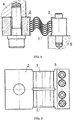
- Fig. 1 is a device for electrically connecting components situated inside a nuclear fusion reactor chamber to a vacuum vessel of a reactor (a side view)
- Fig. 2 is the device according to Fig. 1 (a plane view)
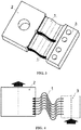
- Fig. 3 is the isometric view of the device
- Fig. 4 is a diagram of Z-shaped current flow through the device.
- a device for electrically connecting components situated inside a nuclear fusion reactor chamber to a vacuum vessel of the reactor comprises two identical stacks of electrically conductive plates 1 and flanges 2, 3 for attachment to a vacuum vessel 4 and a component 5 situated inside a chamber, respectively.
- Said stacks of electrically conductive plates are mounted with mirror symmetry about a line that passes through the centers of symmetry of the flanges 2, 3.
- the electrically conductive plates 1 are in the shape of a symmetrical wave having at least one full period. Based on the layout needs, surfaces of the electrically conductive plates 1 can be in the shape of a symmetrical wave having more than one full period.
- the electrically conductive plates 1 are nested one inside another by means of tongues and corresponding slots and jointed to the flanges 2, 3 for attachment to the component 4 situated inside the chamber and the vacuum vessel 5, for instance, by means of a mechanical, brazed or welded joint, or made integral (one-piece) with the flanges.
- the plates 1 in stacks are arranged so that a generatrix of a wave of the electrically conductive plate 1 passes in a plane which is parallel to contact surfaces of the flanges 2 and 3.
- the flanges 2 and 3 are provided with mounting holes for attachment to the vacuum vessel 4 and the component 5 situated inside the chamber (a blanket module) of the reactor.
- the device functions as follows.
- a great transient current which varies in some modes at a frequency that causes a drastic skin effect, is required to be drained from the component 5 situated inside the chamber to the vacuum vessel 4 of the fusion reactor.
- the current flows into the device from the component 5 situated into the chamber through the flange 2. From the flange 2, the current flows inside the device via two stacks of electrically conductive plates 1 towards the flange 3. From the device, and via the flange 3, the current flows into the vacuum vessel 4 of the fusion reactor.
- the skin effect can be substantially uniform.
- the forces of attraction between outermost electrically conductive plates 1 and central electrically conductive plates which are associated with a uni-directional current are lower in the case of electrically conductive plates 1 gathered in two stacks, rather than in one stack, and current density distribution is uniform per electrically conductive plate 1.
Landscapes
- Physics & Mathematics (AREA)
- Engineering & Computer Science (AREA)
- Plasma & Fusion (AREA)
- General Engineering & Computer Science (AREA)
- High Energy & Nuclear Physics (AREA)
- Plasma Technology (AREA)
- Physical Or Chemical Processes And Apparatus (AREA)
Abstract
Description
- The invention relates to the thermonuclear fusion and can be used in devices for electrically connecting components situated inside a nuclear fusion reactor chamber to the vacuum vessel of the reactor.
- It is known the device for electrically connecting components situated inside the nuclear fusion reactor chamber to the vacuum vessel of the reactor, comprising electrically conductive plates, nested in one stack, with differently directed surface areas provided between flanges for attachment to the component situated inside the chamber and to the vacuum vessel (International Atomic Energy Agency (MAΓAT), Vienna, 2002 ITER TECHNICAL BASIS, ITER EDA Documentation series No.24, Plant Description Document, Chapter 2.3, Page 10 - 2.3.4.3 Electrical Connection, Figure 2.3.4-4 One Strap of the Electrical Connection).

- In the known device, the surface of plates with differently directed surface areas is L-shaped and is perforated. The plates are nested one inside another to form a single U-shaped stack. In the known device, due to perforations and folds in the plates, the stack of electrically conductive plates is insufficiently compliant in the direction normal to the plane of the side parts. In addition, as far as the electrically conductive plates have vertical sections guiding electrical current perpendicularly to the main (toroidal) magnetic field component, this can result in higher electromagnetic forces acting on the device.
- The drawback of the known device is that in a case of plasma disruption it has a limited current loading capacity when a current flows therethrough. The current which flows perpendicularly to the magnetic field (the maximal value of a magnetic field toroidal component of a tokamak can be about 9 T) applies a great force on the device which can be several dozens of kilonewtons. The maximal force acts on a conductor which is perpendicular to the magnetic field. Therefore, the current loading capacity of the known device is limited by the compliance of the stack of electrically conductive plate elements, the magnetic field toroidal component of a nuclear fusion reactor, and by the presence of electrically conductive regions of the device which are perpendicular to the magnetic field.
- The set of features closest to the claimed invention has the device for electrically connecting components situated inside the nuclear fusion reactor chamber to the vacuum vessel of the reactor, comprising electrically conductive plates in the shape of a symmetrical wave having at least one full period, nested one inside another and connected to flanges for attachment to the component situated inside the chamber and to the vacuum vessel (see
RU Patent 2579444 - The drawback of the known device is its reduced current loading capacity while nonpermanent (alternating or pulse) current flowing therethrough. This can be explained by that the electrically conductive plates in a stack center conduct significantly less nonpermanent current than plates outside the stack, which is caused by the surface effect or the skin effect. A further drawback of the known device is the reduced current loading capacity associated with a local increase in current density of electrically conductive plates appearing at junction (transition) points between the plates and the flanges, i.e., the most proximate points to current supply and drainage sites. This can be explained by that the plates in the stack are arranged so that a generatrix of a plate symmetrical wave is in a plane which is perpendicular to flange contact surfaces.
- The object of the present invention is to increase the current loading capacity of a device for electrically connecting components situated inside a nuclear fusion reactor chamber to a vacuum vessel of a reactor when a nonpermanent (alternating or pulse) current flows through electrically conductive plates.
- The technical result of the present invention is that of ensuring a substantially identical skin effect on all of the electrically conductive plates of the device. In addition, the technical effect of this is reducing the force of attraction between the outermost and center plates (the force of attraction between conductors carrying unidirectional currents) and providing uniform current density distribution in each electrically conductive plate.
- Said technical effect is achieved by that the known device for electrically connecting components situated inside a nuclear fusion reactor chamber to a vacuum vessel of a reactor, comprising electrically conductive plates in the shape of a symmetrical wave having at least one full period, nested one inside another and connected to flanges for attachment to the component situated inside the chamber and to the vacuum vessel, according to the present invention is provided with a second identical stack of electrically conductive plates, wherein said stacks are mounted with mirror symmetry about a line that passes through the centers of symmetry of the flanges.
- In addition, plates in stacks are arranged so that a generatrix of an electrically conductive plate wave is in a plane which is parallel to flange contact surfaces.
- Two stacks in the device reduce attractive forces between outermost electrically conductive plates and central electrically conductive plates (attractive forces of conductors with a uni-directional current) because the number of plates in the stack is twice less than in the device generally. Two plate stacks mounted with mirror symmetry and plates mounted along the generatrix in the plane which is parallel to the flange contact surfaces allow minimizing the skin effect-associated uneven current distribution among the plates. In addition, in the device according to the present invention, it is possible to implement a Z-shaped connection scheme, thus, ensuring as even as possible distribution of current among plates. Said technical effects can increase the loading capacity of the device or can reduce dimensions of the device while keeping the same loading capacity as in the prior art.
- The subject matter of the present invention is described by the drawings, where:
Fig. 1 is a device for electrically connecting components situated inside a nuclear fusion reactor chamber to a vacuum vessel of a reactor (a side view),Fig. 2 is the device according toFig. 1 (a plane view),Fig. 3 is the isometric view of the device,Fig. 4 is a diagram of Z-shaped current flow through the device. - A device for electrically connecting components situated inside a nuclear fusion reactor chamber to a vacuum vessel of the reactor comprises two identical stacks of electrically
conductive plates 1 andflanges component 5 situated inside a chamber, respectively. Said stacks of electrically conductive plates are mounted with mirror symmetry about a line that passes through the centers of symmetry of theflanges conductive plates 1 are in the shape of a symmetrical wave having at least one full period. Based on the layout needs, surfaces of the electricallyconductive plates 1 can be in the shape of a symmetrical wave having more than one full period. In each stack, the electricallyconductive plates 1 are nested one inside another by means of tongues and corresponding slots and jointed to theflanges vacuum vessel 5, for instance, by means of a mechanical, brazed or welded joint, or made integral (one-piece) with the flanges. Theplates 1 in stacks are arranged so that a generatrix of a wave of the electricallyconductive plate 1 passes in a plane which is parallel to contact surfaces of theflanges flanges component 5 situated inside the chamber (a blanket module) of the reactor. - The device functions as follows.
- If plasma is disrupted, a great transient current, which varies in some modes at a frequency that causes a drastic skin effect, is required to be drained from the
component 5 situated inside the chamber to the vacuum vessel 4 of the fusion reactor. The current flows into the device from thecomponent 5 situated into the chamber through theflange 2. From theflange 2, the current flows inside the device via two stacks of electricallyconductive plates 1 towards theflange 3. From the device, and via theflange 3, the current flows into the vacuum vessel 4 of the fusion reactor. When the current flows via the electricallyconductive plates 1, thanks to two stacks and the generatrices of the electricallyconductive plates 1 parallel to the contact surfaces of theflanges conductive plates 1 of the device, the skin effect can be substantially uniform. In addition, the forces of attraction between outermost electricallyconductive plates 1 and central electrically conductive plates which are associated with a uni-directional current, are lower in the case of electricallyconductive plates 1 gathered in two stacks, rather than in one stack, and current density distribution is uniform per electricallyconductive plate 1.
Claims (2)
- A device for electrically connecting components situated inside a nuclear fusion reactor chamber to a vacuum vessel of a reactor, comprising electrically conductive plates in the shape of a symmetrical wave having at least one full period, nested one inside another and jointed to flanges for attachment to the component situated inside the chamber and to the vacuum vessel, characterized in that it is provided with a second identical stack of electrically conductive plates, wherein said stacks are mounted with mirror symmetry about a line that passes through the centers of symmetry of the flanges.
- The device according to claim 1, characterized in that the plates in stacks are arranged so that a generatrix of an electrically conductive plate wave is in a plane which is parallel to the flange contact surfaces.
Applications Claiming Priority (2)
| Application Number | Priority Date | Filing Date | Title |
|---|---|---|---|
| RU2016137225A RU2639320C1 (en) | 2016-09-16 | 2016-09-16 | Device for electrical connecting intrachamber components with vacuum case of thermonuclear reactor |
| PCT/RU2017/000639 WO2018063026A1 (en) | 2016-09-16 | 2017-09-01 | Vacuum plasma reactor |
Publications (3)
| Publication Number | Publication Date |
|---|---|
| EP3514802A1 true EP3514802A1 (en) | 2019-07-24 |
| EP3514802A4 EP3514802A4 (en) | 2020-03-25 |
| EP3514802B1 EP3514802B1 (en) | 2021-08-18 |
Family
ID=61763574
Family Applications (1)
| Application Number | Title | Priority Date | Filing Date |
|---|---|---|---|
| EP17856884.6A Active EP3514802B1 (en) | 2016-09-16 | 2017-09-01 | Device for electrically connecting components situated inside a nuclear fusion reactor chamber to a vacuum vessel of the reactor |
Country Status (8)
| Country | Link |
|---|---|
| US (1) | US10943702B2 (en) |
| EP (1) | EP3514802B1 (en) |
| JP (2) | JP7005603B2 (en) |
| KR (1) | KR102262868B1 (en) |
| CN (1) | CN109791809B (en) |
| ES (1) | ES2898384T3 (en) |
| RU (1) | RU2639320C1 (en) |
| WO (1) | WO2018063026A1 (en) |
Families Citing this family (1)
| Publication number | Priority date | Publication date | Assignee | Title |
|---|---|---|---|---|
| RU2700923C1 (en) * | 2019-01-30 | 2019-09-24 | Российская Федерация, от имени которой выступает Государственная корпорация по атомной энергии "Росатом" | Device for electrical connection of in-chamber components with a vacuum housing of a thermonuclear reactor |
Family Cites Families (16)
| Publication number | Priority date | Publication date | Assignee | Title |
|---|---|---|---|---|
| JPS6180088A (en) * | 1984-09-28 | 1986-04-23 | 株式会社東芝 | Vacuum vessel for nuclear fusion device |
| DE3438826C1 (en) * | 1984-10-23 | 1986-02-27 | Spinner GmbH Elektrotechnische Fabrik, 8000 München | Compensation element for rigid RF lines which are filled with compressed gas |
| JPH05113487A (en) * | 1991-10-21 | 1993-05-07 | Mitsubishi Atom Power Ind Inc | Nuclear fusion device |
| DE4241927C2 (en) * | 1992-12-11 | 1994-09-22 | Max Planck Gesellschaft | Self-supporting, insulated electrode arrangement suitable for arrangement in a vacuum vessel, in particular antenna coil for a high-frequency plasma generator |
| CN2496164Y (en) * | 2001-06-16 | 2002-06-19 | 吴县市宝联机电修造有限公司 | Large loading current flexible connection unit |
| JP3845690B2 (en) * | 2002-08-02 | 2006-11-15 | 独立行政法人 日本原子力研究開発機構 | Fusion reactor vacuum exhaust system |
| AT6636U1 (en) * | 2003-04-02 | 2004-01-26 | Plansee Ag | COMPOSITE COMPONENT FOR FUSION REACTOR |
| US9607719B2 (en) * | 2005-03-07 | 2017-03-28 | The Regents Of The University Of California | Vacuum chamber for plasma electric generation system |
| JP2006349369A (en) * | 2005-06-13 | 2006-12-28 | Mitsubishi Heavy Ind Ltd | Vacuum vessel of nuclear fusion apparatus and vacuum joint structure |
| US9607720B2 (en) * | 2008-02-27 | 2017-03-28 | Starfire Industries Llc | Long life high efficiency neutron generator |
| DE102008023761B9 (en) * | 2008-05-09 | 2012-11-08 | Feinmetall Gmbh | Electrical contact element for contact contacting of electrical specimens and corresponding contacting arrangement |
| US20110216866A1 (en) * | 2010-03-08 | 2011-09-08 | Timothy Raymond Pearson | Method and apparatus for the production of nuclear fusion |
| CN103187106A (en) * | 2011-12-28 | 2013-07-03 | 核工业西南物理研究院 | Test blanket module for international thermonuclear experimental reactor with low toroidal field waviness |
| RU118100U8 (en) * | 2012-02-06 | 2012-11-20 | Российская Федерация, от имени которой выступает Государственная корпорация по атомной энергии "Росатом" | DEVICE FOR ELECTRIC CIRCUIT OF IN-CAMERA COMPONENTS ON THE VACUUM HOUSING OF THE THERMONUCLEAR REACTOR |
| RU2579444C1 (en) * | 2015-05-22 | 2016-04-10 | Российская Федерация, от имени которой выступает Государственная корпорация по атомной энергии "Росатом" | Device for electrical connection of intra-chamber components with vacuum housing of thermonuclear reactor |
| RU2670282C2 (en) * | 2016-02-01 | 2018-10-22 | Российская Федерация, от имени которой выступает Государственная корпорация по атомной энергии "Росатом" | Device for electrical connection of intra-chamber components with vacuum housing of thermonuclear reactor |
-
2016
- 2016-09-16 RU RU2016137225A patent/RU2639320C1/en active
-
2017
- 2017-09-01 KR KR1020197007279A patent/KR102262868B1/en active Active
- 2017-09-01 CN CN201780056987.0A patent/CN109791809B/en active Active
- 2017-09-01 US US16/334,050 patent/US10943702B2/en active Active
- 2017-09-01 WO PCT/RU2017/000639 patent/WO2018063026A1/en not_active Ceased
- 2017-09-01 ES ES17856884T patent/ES2898384T3/en active Active
- 2017-09-01 EP EP17856884.6A patent/EP3514802B1/en active Active
- 2017-09-01 JP JP2019515367A patent/JP7005603B2/en active Active
-
2021
- 2021-03-24 JP JP2021050046A patent/JP2021113812A/en active Pending
Also Published As
| Publication number | Publication date |
|---|---|
| US20190259502A1 (en) | 2019-08-22 |
| KR102262868B1 (en) | 2021-06-08 |
| RU2639320C1 (en) | 2017-12-21 |
| JP2019533147A (en) | 2019-11-14 |
| EP3514802B1 (en) | 2021-08-18 |
| US10943702B2 (en) | 2021-03-09 |
| EP3514802A4 (en) | 2020-03-25 |
| JP7005603B2 (en) | 2022-01-21 |
| WO2018063026A1 (en) | 2018-04-05 |
| KR20190060764A (en) | 2019-06-03 |
| ES2898384T3 (en) | 2022-03-07 |
| CN109791809A (en) | 2019-05-21 |
| CN109791809B (en) | 2023-03-07 |
| JP2021113812A (en) | 2021-08-05 |
Similar Documents
| Publication | Publication Date | Title |
|---|---|---|
| EP2033303B1 (en) | Power supply for electrostatic precipitator | |
| US10910140B2 (en) | Matrix transformer and winding structure | |
| JP6265441B2 (en) | Multi-string inverter having input side EMC filter | |
| CN106160412B (en) | The energy conversion device of power module and the application power module | |
| JP2017143250A (en) | Multi-pulse electromagnetic device including linear magnetic core configuration | |
| EP3514802B1 (en) | Device for electrically connecting components situated inside a nuclear fusion reactor chamber to a vacuum vessel of the reactor | |
| US20120229977A1 (en) | Coaxial Capacitor Bus Termination | |
| CN105632712A (en) | High-frequency, high-voltage and high-power rectification transformer | |
| JP2008288770A (en) | EBG material | |
| KR101764431B1 (en) | Single-phased frequency tripling generation device and high frequency generation device | |
| EP3413397B1 (en) | Electrical connection of elements inside the chamber of a nuclear fusion reactor to the reactor vessel | |
| US20230187117A1 (en) | Common Mode Choke | |
| JP4702141B2 (en) | Power converter | |
| CN214203436U (en) | Transformer copper shielding structure | |
| KR102588197B1 (en) | Converter valve valve layer device and converter valve | |
| EP3713027A1 (en) | Bus bar arrangement with magnetic shielding between the conductive bars | |
| JP4041069B2 (en) | Electromagnetic induction heating cooker | |
| US20220093313A1 (en) | Power electronic transformer structure | |
| CN207458731U (en) | A kind of new type of safe transformer | |
| EP3839990B1 (en) | Coil assemblies for power conversion circuits | |
| EP3068014A1 (en) | Energy conversion and storage device using electromagnetic wave | |
| CN101443861B (en) | Reactor shielding | |
| JP6008491B2 (en) | High frequency generator | |
| CN110349729A (en) | A kind of low-temperature-rise type reactor | |
| RO125364A2 (en) | Elctromagnetic source of mechanical vibrations for treating liquids |
Legal Events
| Date | Code | Title | Description |
|---|---|---|---|
| STAA | Information on the status of an ep patent application or granted ep patent |
Free format text: STATUS: THE INTERNATIONAL PUBLICATION HAS BEEN MADE |
|
| PUAI | Public reference made under article 153(3) epc to a published international application that has entered the european phase |
Free format text: ORIGINAL CODE: 0009012 |
|
| STAA | Information on the status of an ep patent application or granted ep patent |
Free format text: STATUS: REQUEST FOR EXAMINATION WAS MADE |
|
| 17P | Request for examination filed |
Effective date: 20190313 |
|
| AK | Designated contracting states |
Kind code of ref document: A1 Designated state(s): AL AT BE BG CH CY CZ DE DK EE ES FI FR GB GR HR HU IE IS IT LI LT LU LV MC MK MT NL NO PL PT RO RS SE SI SK SM TR |
|
| AX | Request for extension of the european patent |
Extension state: BA ME |
|
| DAV | Request for validation of the european patent (deleted) | ||
| DAX | Request for extension of the european patent (deleted) | ||
| REG | Reference to a national code |
Ref country code: DE Ref legal event code: R079 Ref document number: 602017044466 Country of ref document: DE Free format text: PREVIOUS MAIN CLASS: G21B0001170000 Ipc: G21B0001130000 |
|
| A4 | Supplementary search report drawn up and despatched |
Effective date: 20200224 |
|
| RIC1 | Information provided on ipc code assigned before grant |
Ipc: G21B 1/17 20060101ALI20200218BHEP Ipc: G21B 1/13 20060101AFI20200218BHEP |
|
| GRAP | Despatch of communication of intention to grant a patent |
Free format text: ORIGINAL CODE: EPIDOSNIGR1 |
|
| STAA | Information on the status of an ep patent application or granted ep patent |
Free format text: STATUS: GRANT OF PATENT IS INTENDED |
|
| INTG | Intention to grant announced |
Effective date: 20210209 |
|
| GRAS | Grant fee paid |
Free format text: ORIGINAL CODE: EPIDOSNIGR3 |
|
| GRAA | (expected) grant |
Free format text: ORIGINAL CODE: 0009210 |
|
| STAA | Information on the status of an ep patent application or granted ep patent |
Free format text: STATUS: THE PATENT HAS BEEN GRANTED |
|
| AK | Designated contracting states |
Kind code of ref document: B1 Designated state(s): AL AT BE BG CH CY CZ DE DK EE ES FI FR GB GR HR HU IE IS IT LI LT LU LV MC MK MT NL NO PL PT RO RS SE SI SK SM TR |
|
| REG | Reference to a national code |
Ref country code: GB Ref legal event code: FG4D |
|
| REG | Reference to a national code |
Ref country code: CH Ref legal event code: EP |
|
| REG | Reference to a national code |
Ref country code: DE Ref legal event code: R096 Ref document number: 602017044466 Country of ref document: DE |
|
| REG | Reference to a national code |
Ref country code: IE Ref legal event code: FG4D Ref country code: AT Ref legal event code: REF Ref document number: 1422365 Country of ref document: AT Kind code of ref document: T Effective date: 20210915 |
|
| REG | Reference to a national code |
Ref country code: LT Ref legal event code: MG9D |
|
| REG | Reference to a national code |
Ref country code: NL Ref legal event code: MP Effective date: 20210818 |
|
| REG | Reference to a national code |
Ref country code: AT Ref legal event code: MK05 Ref document number: 1422365 Country of ref document: AT Kind code of ref document: T Effective date: 20210818 |
|
| PG25 | Lapsed in a contracting state [announced via postgrant information from national office to epo] |
Ref country code: NO Free format text: LAPSE BECAUSE OF FAILURE TO SUBMIT A TRANSLATION OF THE DESCRIPTION OR TO PAY THE FEE WITHIN THE PRESCRIBED TIME-LIMIT Effective date: 20211118 Ref country code: PT Free format text: LAPSE BECAUSE OF FAILURE TO SUBMIT A TRANSLATION OF THE DESCRIPTION OR TO PAY THE FEE WITHIN THE PRESCRIBED TIME-LIMIT Effective date: 20211220 Ref country code: LT Free format text: LAPSE BECAUSE OF FAILURE TO SUBMIT A TRANSLATION OF THE DESCRIPTION OR TO PAY THE FEE WITHIN THE PRESCRIBED TIME-LIMIT Effective date: 20210818 Ref country code: AT Free format text: LAPSE BECAUSE OF FAILURE TO SUBMIT A TRANSLATION OF THE DESCRIPTION OR TO PAY THE FEE WITHIN THE PRESCRIBED TIME-LIMIT Effective date: 20210818 Ref country code: BG Free format text: LAPSE BECAUSE OF FAILURE TO SUBMIT A TRANSLATION OF THE DESCRIPTION OR TO PAY THE FEE WITHIN THE PRESCRIBED TIME-LIMIT Effective date: 20211118 Ref country code: RS Free format text: LAPSE BECAUSE OF FAILURE TO SUBMIT A TRANSLATION OF THE DESCRIPTION OR TO PAY THE FEE WITHIN THE PRESCRIBED TIME-LIMIT Effective date: 20210818 Ref country code: SE Free format text: LAPSE BECAUSE OF FAILURE TO SUBMIT A TRANSLATION OF THE DESCRIPTION OR TO PAY THE FEE WITHIN THE PRESCRIBED TIME-LIMIT Effective date: 20210818 Ref country code: HR Free format text: LAPSE BECAUSE OF FAILURE TO SUBMIT A TRANSLATION OF THE DESCRIPTION OR TO PAY THE FEE WITHIN THE PRESCRIBED TIME-LIMIT Effective date: 20210818 Ref country code: FI Free format text: LAPSE BECAUSE OF FAILURE TO SUBMIT A TRANSLATION OF THE DESCRIPTION OR TO PAY THE FEE WITHIN THE PRESCRIBED TIME-LIMIT Effective date: 20210818 |
|
| PGFP | Annual fee paid to national office [announced via postgrant information from national office to epo] |
Ref country code: GB Payment date: 20211022 Year of fee payment: 5 Ref country code: DE Payment date: 20211025 Year of fee payment: 5 Ref country code: ES Payment date: 20211022 Year of fee payment: 5 |
|
| PG25 | Lapsed in a contracting state [announced via postgrant information from national office to epo] |
Ref country code: PL Free format text: LAPSE BECAUSE OF FAILURE TO SUBMIT A TRANSLATION OF THE DESCRIPTION OR TO PAY THE FEE WITHIN THE PRESCRIBED TIME-LIMIT Effective date: 20210818 Ref country code: LV Free format text: LAPSE BECAUSE OF FAILURE TO SUBMIT A TRANSLATION OF THE DESCRIPTION OR TO PAY THE FEE WITHIN THE PRESCRIBED TIME-LIMIT Effective date: 20210818 Ref country code: GR Free format text: LAPSE BECAUSE OF FAILURE TO SUBMIT A TRANSLATION OF THE DESCRIPTION OR TO PAY THE FEE WITHIN THE PRESCRIBED TIME-LIMIT Effective date: 20211119 |
|
| PGFP | Annual fee paid to national office [announced via postgrant information from national office to epo] |
Ref country code: IT Payment date: 20211124 Year of fee payment: 5 Ref country code: FR Payment date: 20211022 Year of fee payment: 5 |
|
| REG | Reference to a national code |
Ref country code: ES Ref legal event code: FG2A Ref document number: 2898384 Country of ref document: ES Kind code of ref document: T3 Effective date: 20220307 |
|
| PG25 | Lapsed in a contracting state [announced via postgrant information from national office to epo] |
Ref country code: NL Free format text: LAPSE BECAUSE OF FAILURE TO SUBMIT A TRANSLATION OF THE DESCRIPTION OR TO PAY THE FEE WITHIN THE PRESCRIBED TIME-LIMIT Effective date: 20210818 |
|
| PG25 | Lapsed in a contracting state [announced via postgrant information from national office to epo] |
Ref country code: DK Free format text: LAPSE BECAUSE OF FAILURE TO SUBMIT A TRANSLATION OF THE DESCRIPTION OR TO PAY THE FEE WITHIN THE PRESCRIBED TIME-LIMIT Effective date: 20210818 |
|
| REG | Reference to a national code |
Ref country code: CH Ref legal event code: PL |
|
| REG | Reference to a national code |
Ref country code: DE Ref legal event code: R097 Ref document number: 602017044466 Country of ref document: DE |
|
| REG | Reference to a national code |
Ref country code: BE Ref legal event code: MM Effective date: 20210930 |
|
| PG25 | Lapsed in a contracting state [announced via postgrant information from national office to epo] |
Ref country code: SM Free format text: LAPSE BECAUSE OF FAILURE TO SUBMIT A TRANSLATION OF THE DESCRIPTION OR TO PAY THE FEE WITHIN THE PRESCRIBED TIME-LIMIT Effective date: 20210818 Ref country code: SK Free format text: LAPSE BECAUSE OF FAILURE TO SUBMIT A TRANSLATION OF THE DESCRIPTION OR TO PAY THE FEE WITHIN THE PRESCRIBED TIME-LIMIT Effective date: 20210818 Ref country code: RO Free format text: LAPSE BECAUSE OF FAILURE TO SUBMIT A TRANSLATION OF THE DESCRIPTION OR TO PAY THE FEE WITHIN THE PRESCRIBED TIME-LIMIT Effective date: 20210818 Ref country code: MC Free format text: LAPSE BECAUSE OF FAILURE TO SUBMIT A TRANSLATION OF THE DESCRIPTION OR TO PAY THE FEE WITHIN THE PRESCRIBED TIME-LIMIT Effective date: 20210818 Ref country code: EE Free format text: LAPSE BECAUSE OF FAILURE TO SUBMIT A TRANSLATION OF THE DESCRIPTION OR TO PAY THE FEE WITHIN THE PRESCRIBED TIME-LIMIT Effective date: 20210818 Ref country code: CZ Free format text: LAPSE BECAUSE OF FAILURE TO SUBMIT A TRANSLATION OF THE DESCRIPTION OR TO PAY THE FEE WITHIN THE PRESCRIBED TIME-LIMIT Effective date: 20210818 Ref country code: AL Free format text: LAPSE BECAUSE OF FAILURE TO SUBMIT A TRANSLATION OF THE DESCRIPTION OR TO PAY THE FEE WITHIN THE PRESCRIBED TIME-LIMIT Effective date: 20210818 |
|
| PLBE | No opposition filed within time limit |
Free format text: ORIGINAL CODE: 0009261 |
|
| STAA | Information on the status of an ep patent application or granted ep patent |
Free format text: STATUS: NO OPPOSITION FILED WITHIN TIME LIMIT |
|
| 26N | No opposition filed |
Effective date: 20220519 |
|
| PG25 | Lapsed in a contracting state [announced via postgrant information from national office to epo] |
Ref country code: LU Free format text: LAPSE BECAUSE OF NON-PAYMENT OF DUE FEES Effective date: 20210901 Ref country code: BE Free format text: LAPSE BECAUSE OF NON-PAYMENT OF DUE FEES Effective date: 20210930 Ref country code: IE Free format text: LAPSE BECAUSE OF NON-PAYMENT OF DUE FEES Effective date: 20210901 |
|
| PG25 | Lapsed in a contracting state [announced via postgrant information from national office to epo] |
Ref country code: SI Free format text: LAPSE BECAUSE OF FAILURE TO SUBMIT A TRANSLATION OF THE DESCRIPTION OR TO PAY THE FEE WITHIN THE PRESCRIBED TIME-LIMIT Effective date: 20210818 Ref country code: LI Free format text: LAPSE BECAUSE OF NON-PAYMENT OF DUE FEES Effective date: 20210930 Ref country code: CH Free format text: LAPSE BECAUSE OF NON-PAYMENT OF DUE FEES Effective date: 20210930 |
|
| REG | Reference to a national code |
Ref country code: DE Ref legal event code: R119 Ref document number: 602017044466 Country of ref document: DE |
|
| GBPC | Gb: european patent ceased through non-payment of renewal fee |
Effective date: 20220901 |
|
| PG25 | Lapsed in a contracting state [announced via postgrant information from national office to epo] |
Ref country code: CY Free format text: LAPSE BECAUSE OF FAILURE TO SUBMIT A TRANSLATION OF THE DESCRIPTION OR TO PAY THE FEE WITHIN THE PRESCRIBED TIME-LIMIT Effective date: 20210818 |
|
| PG25 | Lapsed in a contracting state [announced via postgrant information from national office to epo] |
Ref country code: HU Free format text: LAPSE BECAUSE OF FAILURE TO SUBMIT A TRANSLATION OF THE DESCRIPTION OR TO PAY THE FEE WITHIN THE PRESCRIBED TIME-LIMIT; INVALID AB INITIO Effective date: 20170901 Ref country code: FR Free format text: LAPSE BECAUSE OF NON-PAYMENT OF DUE FEES Effective date: 20220930 Ref country code: DE Free format text: LAPSE BECAUSE OF NON-PAYMENT OF DUE FEES Effective date: 20230401 |
|
| REG | Reference to a national code |
Ref country code: ES Ref legal event code: FD2A Effective date: 20231026 |
|
| PG25 | Lapsed in a contracting state [announced via postgrant information from national office to epo] |
Ref country code: IT Free format text: LAPSE BECAUSE OF NON-PAYMENT OF DUE FEES Effective date: 20220901 Ref country code: GB Free format text: LAPSE BECAUSE OF NON-PAYMENT OF DUE FEES Effective date: 20220901 |
|
| PG25 | Lapsed in a contracting state [announced via postgrant information from national office to epo] |
Ref country code: ES Free format text: LAPSE BECAUSE OF NON-PAYMENT OF DUE FEES Effective date: 20220902 |
|
| PG25 | Lapsed in a contracting state [announced via postgrant information from national office to epo] |
Ref country code: ES Free format text: LAPSE BECAUSE OF NON-PAYMENT OF DUE FEES Effective date: 20220902 |
|
| PG25 | Lapsed in a contracting state [announced via postgrant information from national office to epo] |
Ref country code: MK Free format text: LAPSE BECAUSE OF FAILURE TO SUBMIT A TRANSLATION OF THE DESCRIPTION OR TO PAY THE FEE WITHIN THE PRESCRIBED TIME-LIMIT Effective date: 20210818 |
|
| PG25 | Lapsed in a contracting state [announced via postgrant information from national office to epo] |
Ref country code: MT Free format text: LAPSE BECAUSE OF FAILURE TO SUBMIT A TRANSLATION OF THE DESCRIPTION OR TO PAY THE FEE WITHIN THE PRESCRIBED TIME-LIMIT Effective date: 20210818 |
|
| PG25 | Lapsed in a contracting state [announced via postgrant information from national office to epo] |
Ref country code: TR Free format text: LAPSE BECAUSE OF FAILURE TO SUBMIT A TRANSLATION OF THE DESCRIPTION OR TO PAY THE FEE WITHIN THE PRESCRIBED TIME-LIMIT Effective date: 20210818 |