EP3514777A1 - Electrochromic device for safety detector - Google Patents
Electrochromic device for safety detector Download PDFInfo
- Publication number
- EP3514777A1 EP3514777A1 EP19151994.1A EP19151994A EP3514777A1 EP 3514777 A1 EP3514777 A1 EP 3514777A1 EP 19151994 A EP19151994 A EP 19151994A EP 3514777 A1 EP3514777 A1 EP 3514777A1
- Authority
- EP
- European Patent Office
- Prior art keywords
- detector
- electrochromic material
- condition
- power source
- visual display
- Prior art date
- Legal status (The legal status is an assumption and is not a legal conclusion. Google has not performed a legal analysis and makes no representation as to the accuracy of the status listed.)
- Granted
Links
Images

Classifications
-
- G—PHYSICS
- G08—SIGNALLING
- G08B—SIGNALLING SYSTEMS, e.g. PERSONAL CALLING SYSTEMS; ORDER TELEGRAPHS; ALARM SYSTEMS
- G08B29/00—Checking or monitoring of signalling or alarm systems; Prevention or correction of operating errors, e.g. preventing unauthorised operation
- G08B29/18—Prevention or correction of operating errors
- G08B29/181—Prevention or correction of operating errors due to failing power supply
-
- G—PHYSICS
- G08—SIGNALLING
- G08B—SIGNALLING SYSTEMS, e.g. PERSONAL CALLING SYSTEMS; ORDER TELEGRAPHS; ALARM SYSTEMS
- G08B29/00—Checking or monitoring of signalling or alarm systems; Prevention or correction of operating errors, e.g. preventing unauthorised operation
- G08B29/02—Monitoring continuously signalling or alarm systems
- G08B29/04—Monitoring of the detection circuits
- G08B29/043—Monitoring of the detection circuits of fire detection circuits
-
- G—PHYSICS
- G08—SIGNALLING
- G08B—SIGNALLING SYSTEMS, e.g. PERSONAL CALLING SYSTEMS; ORDER TELEGRAPHS; ALARM SYSTEMS
- G08B17/00—Fire alarms; Alarms responsive to explosion
- G08B17/10—Actuation by presence of smoke or gases, e.g. automatic alarm devices for analysing flowing fluid materials by the use of optical means
-
- G—PHYSICS
- G08—SIGNALLING
- G08B—SIGNALLING SYSTEMS, e.g. PERSONAL CALLING SYSTEMS; ORDER TELEGRAPHS; ALARM SYSTEMS
- G08B21/00—Alarms responsive to a single specified undesired or abnormal condition and not otherwise provided for
- G08B21/02—Alarms for ensuring the safety of persons
- G08B21/12—Alarms for ensuring the safety of persons responsive to undesired emission of substances, e.g. pollution alarms
- G08B21/14—Toxic gas alarms
Definitions
- the present invention relates to a detector using an electrochromic material.
- the detector is for detecting a hazardous safety condition and it may be a smoke and/or a carbon monoxide detector including an electrochromic device.
- detectors typically indicate a state or condition with audible sounds (e.g., beeps or voice messages) and/or flashing or persistent lights (e.g., LEDs).
- audible sounds e.g., beeps or voice messages
- flashing or persistent lights e.g., LEDs
- Optical indicators can be challenging to interpret as to the condition they indicate and require constant power for illumination. It is possible for an end of life detector to beep and/or flash until its battery is fully exhausted, at which point it has no way to indicate it has reached an end of life state.
- the invention provides a detector for detecting a hazardous safety condition, the detector being as described in claim 1.
- the detector includes a housing, an electrochromic material disposed within the housing, and a power source in operative electrical communication with the electrochromic material, the electrochromic material providing a visual display to indicate a condition of the detector.
- the power source may be in operative electrical communication with the electrochromic material with at least one electrode.
- the at least one electrode may comprise a first electrode and a second electrode, the first and second electrodes disposed adjacent the electrochromic material on opposing sides of the electrochromic material.
- the at least one electrode may be in electrical communication with the power source.
- the power source may is a lithium ion battery.
- the power source may be a capacitor charged by a battery.
- the power source may include a battery employed to power the detector.
- the visual display to indicate a condition of the detector may include at least one of a change in color, symbol, and text.
- the visual display to indicate a condition of the detector may be maintained after the power source has reached an end of life condition.
- condition of the detector is an end of life battery condition.
- the electrochromic material provides a plurality of visual displays indicative of a plurality of conditions of the detector.
- the electrochromic material may be one of a plurality of electrochromic materials disposed within the housing.
- the electrochromic material may be a polymer based material.
- the detector may be one of a smoke detector and a carbon monoxide detector.
- the invention provides a method of visually displaying a condition of a detector, which may be a detector as described above, such as being one of a smoke detector and a carbon monoxide detector.
- the method includes applying an electric field across an electrochromic material disposed within a housing of the detector.
- the method also includes changing a visual display provided by the electrochromic material in response to application of the electric field.
- the electric field may be applied with a power source in operative electric communication with a pair of electrodes disposed adjacent the electrochromic material.
- the method may include maintaining the visual display after the power source has reached an end of life condition.
- the method may include powering the detector with the power source.
- FIG. 1 shows a safety condition detector generally referenced with numeral 10.
- the detector 10 is a smoke detector in some embodiments, but it is to be appreciated that other types of detectors may benefit from the features of the embodiments described herein.
- a carbon monoxide detector may incorporate the features of the embodiments described herein.
- the detector 10 is operable to sense the presence of smoke particles and to generate or initiate an alarm signal.
- the detector 10 may be realized as a stand-alone system or may be part of a safety monitoring system comprising a plurality of detectors.
- FIG. 2 illustrates an electrochromic device 20 for assembly in the detector 10.
- the electrochromic device 20 is shown as having a generally semi-cylindrical geometry, but it is to be appreciated that the illustration is merely one example of many suitable geometric configurations. Furthermore, the electrochromic device 20 can be considered as an independent flexible indicator therefore can conform to a curved surface. The precise configuration may vary depending upon the particular type of detector 10 to which it is installed.
- the electrochromic device 20 may be installed in any suitable location within (or on) a housing 22 (referenced in FIG. 1 ) of the detector 10.
- the electrochromic device 20 includes an electrochromic material 24, such as those made commercially available by SageGlass®, Polytronix, Inc.TM, or Sono-Tek Corp.
- the electrochromic material 24 is disposed proximate to a pair of electrodes, represented generally as a first electrode 26 and a second electrode 28.
- the electrochromic material 24 may be a polymer based material in some embodiments.
- the electrodes 26, 28 are located immediately adjacent to the electrochromic material 24 in the illustrated embodiment, but it is contemplated that intermediate materials or components may be located between the electrodes 26, 28 and the electrochromic material 24. In some embodiments, the electrodes 26, 28 sandwich the electrochromic material 24.
- the electrodes 26, 28 are in electrical communication with a power source 30.
- the power source 30 may be various suitable sources.
- a lithium ion power source may be wired to the electrodes 26, 28.
- a capacitor may be charged by a battery which powers the detector 10, with the capacitor electrically coupled to the electrodes 26, 28 via a switch.
- the electrodes 26, 28 may be in direct electrical communication with a battery that powers the detector 10.
- the electrochromic device 20 provides a persistent visual indicator to inform an owner of at least one state of the detector 10, such as an end of life state when a power source is no longer available, for example.
- the visual indicator of the electrochromic device 20 is activated or changed in response to an application of an electric field across the electrochromic material 24 by the electrodes 26, 28.
- the application of the electric field is initiated in response to a transition of states of the detector 10.
- the electric field actuates a display change in the electrochromic material 24.
- the display change may be represented by a color change.
- the color change may be from a clear state of the electrochromic material to a visible color, or vice versa. Additionally, the color change may be from one visible color to another visible color.
- the display change may include provision of a symbol or text that is indicative of a state of the detector 10.
- the transitions between the above-described visual displays occur as a result of a low voltage change detected by the electrodes 26, 28.
- the electrodes 26, 28 apply the electric field that actuates the visual display change. Due to the properties of the electrochromic material 24, the visual display change occurs at a low power, but the visual display remains in the transitioned state without any further power consumption. Therefore, if a battery level of the detector 10 is low or fully exhausted, a sustainable visual display associated with the battery level may be provided for identification by a user. Such a persistent visual display is more readily identifiable by a user when compared to an indicator that turns off once the power source is exhausted.
- the visual display change(s) may be reversible, such that once battery replacement is performed, the visual display returns to the original state.
- a single electrochromic device 20 is utilized. It is contemplated that a single electrochromic device 20 may include a single electrochromic material. In such embodiments, the single electrochromic material may be utilized to switch between two different states represented by two different visual indicators, one of which may be clear. In some embodiments, a single electrochromic material may include properties that facilitate indication of more than two different states of the detector 10, as represented by more than two different visual displays. Alternatively, multiple electrochromic materials may be provided in one or more electrochromic devices to achieve indication of multiple states of the detector 10.
- one or more electrochromic materials may have a first visual display indicating a normal state of operation of the battery of the detector 10, a second visual display may indicate a low level of the battery, and a third visual display may indicate an end of life state of the battery, such that no power remains.
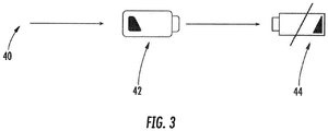
- FIG. 3 illustrates examples of indicators for a transition from a normal operating condition with a clear indicator 40 to a low battery level condition 42 and to an end of life condition 44 of the battery.
- a yellow indicator may indicate the low battery level and a red indicator may indicate the end of life state. Therefore, the embodiments described herein allow for a high degree of customization, as the electrochromic device 20 can be configured to provide shapes, text, and colors in any combination thereof.
- the visual display transitions are actuated by a power change, such as a voltage change provided to the electrodes 26, 28.
- a power change such as a voltage change provided to the electrodes 26, 28.
- the voltage change required for device operation are +/-2V, however, the electrochromic device 20 can operate at any voltage in between that allows for control of color intensity.
- the embodiments described herein provide a clear, user friendly indication of a detector state by utilizing a low power, persistent visual device.
- the electrochromic device 20 facilitates customization of functionally identical products. Also, the embodiments reduce the nuisance of tracking down a low battery "chirp" or not having any visual indicator after complete battery failure.
- an apparatus or system may include one or more processors, and memory storing instructions that, when executed by the one or more processors, cause the apparatus or system to perform one or more methodological acts as described herein.
- Various mechanical components known to those of skill in the art may be used in some embodiments.
- Embodiments may be implemented as one or more apparatuses, systems, and/or methods.
- instructions may be stored on one or more computer program products or computer-readable media, such as a transitory and/or non-transitory computer-readable medium.
- the instructions when executed, may cause an entity (e.g., a processor, apparatus or system) to perform one or more methodological acts as described herein.
Landscapes
- Engineering & Computer Science (AREA)
- Computer Security & Cryptography (AREA)
- Physics & Mathematics (AREA)
- General Physics & Mathematics (AREA)
- Electrochromic Elements, Electrophoresis, Or Variable Reflection Or Absorption Elements (AREA)
Abstract
Description
- This present invention relates to a detector using an electrochromic material. The detector is for detecting a hazardous safety condition and it may be a smoke and/or a carbon monoxide detector including an electrochromic device.
- The ability to detect the presence of fire, smoke, and/or carbon monoxide provides for the safety of occupants and property. Devices relied upon to detect such risk conditions may be generically referred to herein simply as "detectors." Such detectors typically indicate a state or condition with audible sounds (e.g., beeps or voice messages) and/or flashing or persistent lights (e.g., LEDs). In an environment equipped with multiple alarms, relying on audible beeps makes tracking down the identity of a single detector with a low batter chirp is quite difficult. Optical indicators can be challenging to interpret as to the condition they indicate and require constant power for illumination. It is possible for an end of life detector to beep and/or flash until its battery is fully exhausted, at which point it has no way to indicate it has reached an end of life state.
- Viewed from a first aspect, the invention provides a detector for detecting a hazardous safety condition, the detector being as described in claim 1. The detector includes a housing, an electrochromic material disposed within the housing, and a power source in operative electrical communication with the electrochromic material, the electrochromic material providing a visual display to indicate a condition of the detector.
- The power source may be in operative electrical communication with the electrochromic material with at least one electrode.
- The at least one electrode may comprise a first electrode and a second electrode, the first and second electrodes disposed adjacent the electrochromic material on opposing sides of the electrochromic material.
- The at least one electrode may be in electrical communication with the power source.
- The power source may is a lithium ion battery.
- Alternatively the power source may be a capacitor charged by a battery.
- The power source may include a battery employed to power the detector.
- The visual display to indicate a condition of the detector may include at least one of a change in color, symbol, and text.
- The visual display to indicate a condition of the detector may be maintained after the power source has reached an end of life condition.
- Optionally, the condition of the detector is an end of life battery condition.
- Optionally, the electrochromic material provides a plurality of visual displays indicative of a plurality of conditions of the detector.
- The electrochromic material may be one of a plurality of electrochromic materials disposed within the housing.
- The electrochromic material may be a polymer based material.
- The detector may be one of a smoke detector and a carbon monoxide detector.
- Viewed from another aspect, the invention provides a method of visually displaying a condition of a detector, which may be a detector as described above, such as being one of a smoke detector and a carbon monoxide detector. The method includes applying an electric field across an electrochromic material disposed within a housing of the detector. The method also includes changing a visual display provided by the electrochromic material in response to application of the electric field.
- The electric field may be applied with a power source in operative electric communication with a pair of electrodes disposed adjacent the electrochromic material.
- The method may include maintaining the visual display after the power source has reached an end of life condition.
- The method may include powering the detector with the power source.
- Certain example embodiments of the present invention will now be described by way of example only and are illustrated by way of example and not limited in the accompanying figures in which like reference numerals indicate similar elements.
-
FIG. 1 is a top view of a smoke and/or carbon monoxide detector; -
FIG. 2 illustrates an electrochromic device for use with the detector; and -
FIG. 3 is a series of visual displays provided by the electrochromic device. -
FIG. 1 shows a safety condition detector generally referenced withnumeral 10. Thedetector 10 is a smoke detector in some embodiments, but it is to be appreciated that other types of detectors may benefit from the features of the embodiments described herein. For example, a carbon monoxide detector may incorporate the features of the embodiments described herein. In the case of a smoke detector, thedetector 10 is operable to sense the presence of smoke particles and to generate or initiate an alarm signal. Regardless of the particular type of safety condition thedetector 10 is configured to detect, thedetector 10 may be realized as a stand-alone system or may be part of a safety monitoring system comprising a plurality of detectors. -
FIG. 2 illustrates anelectrochromic device 20 for assembly in thedetector 10. Theelectrochromic device 20 is shown as having a generally semi-cylindrical geometry, but it is to be appreciated that the illustration is merely one example of many suitable geometric configurations. Furthermore, theelectrochromic device 20 can be considered as an independent flexible indicator therefore can conform to a curved surface. The precise configuration may vary depending upon the particular type ofdetector 10 to which it is installed. Theelectrochromic device 20 may be installed in any suitable location within (or on) a housing 22 (referenced inFIG. 1 ) of thedetector 10. - The
electrochromic device 20 includes anelectrochromic material 24, such as those made commercially available by SageGlass®, Polytronix, Inc.™, or Sono-Tek Corp. Theelectrochromic material 24 is disposed proximate to a pair of electrodes, represented generally as afirst electrode 26 and asecond electrode 28. Theelectrochromic material 24 may be a polymer based material in some embodiments. Theelectrodes electrochromic material 24 in the illustrated embodiment, but it is contemplated that intermediate materials or components may be located between theelectrodes electrochromic material 24. In some embodiments, theelectrodes electrochromic material 24. Theelectrodes power source 30. Thepower source 30 may be various suitable sources. For example, a lithium ion power source may be wired to theelectrodes detector 10, with the capacitor electrically coupled to theelectrodes electrodes detector 10. - As described herein, the
electrochromic device 20 provides a persistent visual indicator to inform an owner of at least one state of thedetector 10, such as an end of life state when a power source is no longer available, for example. The visual indicator of theelectrochromic device 20 is activated or changed in response to an application of an electric field across theelectrochromic material 24 by theelectrodes detector 10. The electric field actuates a display change in theelectrochromic material 24. The display change may be represented by a color change. The color change may be from a clear state of the electrochromic material to a visible color, or vice versa. Additionally, the color change may be from one visible color to another visible color. In addition, the display change may include provision of a symbol or text that is indicative of a state of thedetector 10. - The transitions between the above-described visual displays occur as a result of a low voltage change detected by the
electrodes power source 30 changes (i.e., current and/or voltage) a certain amount, theelectrodes electrochromic material 24, the visual display change occurs at a low power, but the visual display remains in the transitioned state without any further power consumption. Therefore, if a battery level of thedetector 10 is low or fully exhausted, a sustainable visual display associated with the battery level may be provided for identification by a user. Such a persistent visual display is more readily identifiable by a user when compared to an indicator that turns off once the power source is exhausted. The visual display change(s) may be reversible, such that once battery replacement is performed, the visual display returns to the original state. - In some embodiments, a
single electrochromic device 20 is utilized. It is contemplated that asingle electrochromic device 20 may include a single electrochromic material. In such embodiments, the single electrochromic material may be utilized to switch between two different states represented by two different visual indicators, one of which may be clear. In some embodiments, a single electrochromic material may include properties that facilitate indication of more than two different states of thedetector 10, as represented by more than two different visual displays. Alternatively, multiple electrochromic materials may be provided in one or more electrochromic devices to achieve indication of multiple states of thedetector 10. - By way of example of more than two states being represented, one or more electrochromic materials may have a first visual display indicating a normal state of operation of the battery of the
detector 10, a second visual display may indicate a low level of the battery, and a third visual display may indicate an end of life state of the battery, such that no power remains.FIG. 3 illustrates examples of indicators for a transition from a normal operating condition with aclear indicator 40 to a lowbattery level condition 42 and to an end oflife condition 44 of the battery. These are merely examples and it is to be appreciated that alternative symbols may be used, only colors may be used, or text may be used. Additionally, some combination of symbols, colors or text may be used. For example, a yellow indicator may indicate the low battery level and a red indicator may indicate the end of life state. Therefore, the embodiments described herein allow for a high degree of customization, as theelectrochromic device 20 can be configured to provide shapes, text, and colors in any combination thereof. - As described herein, the visual display transitions are actuated by a power change, such as a voltage change provided to the
electrodes electrochromic device 20 can operate at any voltage in between that allows for control of color intensity. - The embodiments described herein provide a clear, user friendly indication of a detector state by utilizing a low power, persistent visual device. The
electrochromic device 20 facilitates customization of functionally identical products. Also, the embodiments reduce the nuisance of tracking down a low battery "chirp" or not having any visual indicator after complete battery failure. - Embodiments may be implemented using one or more technologies. In some embodiments, an apparatus or system may include one or more processors, and memory storing instructions that, when executed by the one or more processors, cause the apparatus or system to perform one or more methodological acts as described herein. Various mechanical components known to those of skill in the art may be used in some embodiments.
- Embodiments may be implemented as one or more apparatuses, systems, and/or methods. In some embodiments, instructions may be stored on one or more computer program products or computer-readable media, such as a transitory and/or non-transitory computer-readable medium. The instructions, when executed, may cause an entity (e.g., a processor, apparatus or system) to perform one or more methodological acts as described herein.
- While the invention has been described in detail in connection with only a limited number of embodiments, it should be readily understood that the invention is not limited to such disclosed embodiments. Rather, the invention can be modified to incorporate any number of variations, alterations, substitutions or equivalent arrangements not heretofore described, but which are commensurate with the scope of the invention, which is defined by the claims. Accordingly, the invention is not to be seen as limited by the foregoing description, but is only limited by the scope of the appended claims.
Claims (15)
- A detector for detecting a hazardous safety condition, the detector comprising:a housing;an electrochromic material disposed within the housing; anda power source in operative electrical communication with the electrochromic material, the electrochromic material providing a visual display to indicate a condition of the detector.
- The detector of claim 1, wherein the power source is in operative electrical communication with the electrochromic material with at least one electrode.
- The detector of claim 2, wherein the at least one electrode comprises a first electrode and a second electrode, the first and second electrodes disposed adjacent the electrochromic material on opposing sides of the electrochromic material.
- The detector of claim 2 or 3, wherein the at least one electrode is in electrical communication with the power source.
- The detector of any preceding claim, wherein the power source comprises a lithium ion battery; a capacitor charged by a battery and/or is a battery employed to power the detector.
- The detector of any preceding claim, wherein the visual display to indicate a condition of the detector is at least one of a change in color, symbol, and text.
- The detector of any preceding claim, wherein the visual display to indicate a condition of the detector is maintained after the power source has reached an end of life condition.
- The detector of any preceding claim, wherein the condition of the detector is an end of life battery condition.
- The detector of any preceding claim, wherein the electrochromic material provides a plurality of visual displays indicative of a plurality of conditions of the detector.
- The detector of any preceding claim, wherein the electrochromic material is one of a plurality of electrochromic materials disposed within the housing.
- The detector of any preceding claim, wherein the electrochromic material is a polymer based material.
- The detector of any preceding claim, wherein the detector is one of a smoke detector and a carbon monoxide detector.
- A method of visually displaying a condition of a detector, the method comprising:applying an electric field across an electrochromic material disposed within a housing of the detector; andchanging a visual display provided by the electrochromic material in response to application of the electric field.
- The method of claim 13, wherein the detector is a detector as claimed in any of claims 1 to 12.
- The method of claim 13 or 14, wherein the electric field is applied with a power source in operative electric communication with a pair of electrodes disposed adjacent the electrochromic material, the method optionally comprising maintaining the visual display after the power source has reached an end of life condition.
Applications Claiming Priority (1)
| Application Number | Priority Date | Filing Date | Title |
|---|---|---|---|
| US201862618918P | 2018-01-18 | 2018-01-18 |
Publications (2)
| Publication Number | Publication Date |
|---|---|
| EP3514777A1 true EP3514777A1 (en) | 2019-07-24 |
| EP3514777B1 EP3514777B1 (en) | 2021-07-28 |
Family
ID=65033452
Family Applications (1)
| Application Number | Title | Priority Date | Filing Date |
|---|---|---|---|
| EP19151994.1A Active EP3514777B1 (en) | 2018-01-18 | 2019-01-15 | Electrochromic device for safety detector |
Country Status (3)
| Country | Link |
|---|---|
| US (1) | US10825333B2 (en) |
| EP (1) | EP3514777B1 (en) |
| ES (1) | ES2882779T3 (en) |
Families Citing this family (15)
| Publication number | Priority date | Publication date | Assignee | Title |
|---|---|---|---|---|
| US11138853B2 (en) * | 2019-05-17 | 2021-10-05 | Carrier Corporation | Intrusion entry protection |
| US11205331B2 (en) * | 2020-04-15 | 2021-12-21 | Carrier Corporation | Device and a method for providing an indication to a user regarding events |
| US11881093B2 (en) | 2020-08-20 | 2024-01-23 | Denso International America, Inc. | Systems and methods for identifying smoking in vehicles |
| US12017506B2 (en) | 2020-08-20 | 2024-06-25 | Denso International America, Inc. | Passenger cabin air control systems and methods |
| US11636870B2 (en) | 2020-08-20 | 2023-04-25 | Denso International America, Inc. | Smoking cessation systems and methods |
| US12377711B2 (en) | 2020-08-20 | 2025-08-05 | Denso International America, Inc. | Vehicle feature control systems and methods based on smoking |
| US11760169B2 (en) | 2020-08-20 | 2023-09-19 | Denso International America, Inc. | Particulate control systems and methods for olfaction sensors |
| US12251991B2 (en) | 2020-08-20 | 2025-03-18 | Denso International America, Inc. | Humidity control for olfaction sensors |
| US12269315B2 (en) | 2020-08-20 | 2025-04-08 | Denso International America, Inc. | Systems and methods for measuring and managing odor brought into rental vehicles |
| US11760170B2 (en) | 2020-08-20 | 2023-09-19 | Denso International America, Inc. | Olfaction sensor preservation systems and methods |
| US11828210B2 (en) | 2020-08-20 | 2023-11-28 | Denso International America, Inc. | Diagnostic systems and methods of vehicles using olfaction |
| US11932080B2 (en) | 2020-08-20 | 2024-03-19 | Denso International America, Inc. | Diagnostic and recirculation control systems and methods |
| US11813926B2 (en) | 2020-08-20 | 2023-11-14 | Denso International America, Inc. | Binding agent and olfaction sensor |
| CN112002291A (en) * | 2020-09-17 | 2020-11-27 | 努比亚技术有限公司 | Electrochromic film display method, device and computer readable storage medium |
| US12542041B2 (en) | 2023-04-16 | 2026-02-03 | Kidde Fire Protection, Llc | Self-testing smoke detector having an electrochromic film |
Citations (4)
| Publication number | Priority date | Publication date | Assignee | Title |
|---|---|---|---|---|
| US5686896A (en) * | 1995-09-28 | 1997-11-11 | Interactive Technologies, Inc. | Low battery report inhibitor for a sensor |
| EP2264646A1 (en) * | 2004-12-29 | 2010-12-22 | Avery Dennison Corporation | RFID device with visual indicator |
| US20140028461A1 (en) * | 2012-07-24 | 2014-01-30 | Thomas W. NEWTON | Smoke Detector with an Easily-Readable and Highly-Visible Battery-Life Display |
| US20150187234A1 (en) * | 2010-12-30 | 2015-07-02 | Paul Atkinson | Intelligent label device and method |
Family Cites Families (18)
| Publication number | Priority date | Publication date | Assignee | Title |
|---|---|---|---|---|
| JPS50101068A (en) | 1974-01-08 | 1975-08-11 | ||
| US4030086A (en) | 1975-11-10 | 1977-06-14 | General Electric Company | Battery voltage detection and warning means |
| JPS52128099A (en) * | 1976-04-20 | 1977-10-27 | Citizen Watch Co Ltd | Electrochemical color production display device |
| CA2058728C (en) | 1991-01-15 | 1998-11-10 | Jean W. Bailey | Batteries with tester label |
| CA2054008A1 (en) * | 1991-01-31 | 1992-08-01 | Harry R. Huhndorff | Tester for end of cell |
| US5737114A (en) | 1991-01-31 | 1998-04-07 | Eveready Battery Company, Inc. | Label having an incorporated electrochromic state-of-charge indicator for an electrochemical cell |
| CA2056139C (en) * | 1991-01-31 | 2000-08-01 | Eveready Battery Company, Inc. | Electrochromic thin film state-of-charge detector for on-the-cell application |
| IL102794A (en) | 1991-09-24 | 1995-06-29 | Duracell Inc | Battery with electrochemical tester |
| US5830596A (en) | 1993-05-03 | 1998-11-03 | Morgan Adhesives, Inc. | Method for producing battery tester label and resulting label and battery assembly |
| US5574436A (en) | 1993-07-21 | 1996-11-12 | Sisselman; Ronald | Smoke detector including an indicator for indicating a missing primary power source which is powered by a substantially nonremovable secondary power source |
| US5646598A (en) | 1995-05-02 | 1997-07-08 | Nickles; Aaron Michael | Smoke detector with advanced safety features |
| EP2068288A1 (en) | 2007-12-05 | 2009-06-10 | Gmür & Großmann GmbH | Device and method for monitoring the function of a device, in particular a smoke detector |
| US8054188B2 (en) | 2009-01-05 | 2011-11-08 | Utc Fire & Security Americas Corporation, Inc. | Carbon monoxide detector, system and method for signaling a carbon monoxide sensor end-of-life condition |
| DE102012223822A1 (en) | 2012-12-19 | 2014-06-26 | Schneider Electric Industries Sas | smoke detector |
| US9543623B2 (en) * | 2013-12-11 | 2017-01-10 | Duracell U.S. Operations, Inc. | Battery condition indicator |
| US9943116B2 (en) * | 2015-11-17 | 2018-04-17 | Lunatech, Llc | Electronic vapor device warning system |
| US9424797B1 (en) * | 2015-11-17 | 2016-08-23 | Dock Technologies Inc. | Driving electro-optic displays |
| US10033208B2 (en) | 2016-05-12 | 2018-07-24 | Roost, Inc. | Controlling a smoke detector by regulating battery voltage |
-
2019
- 2019-01-15 EP EP19151994.1A patent/EP3514777B1/en active Active
- 2019-01-15 ES ES19151994T patent/ES2882779T3/en active Active
- 2019-01-16 US US16/249,426 patent/US10825333B2/en active Active
Patent Citations (4)
| Publication number | Priority date | Publication date | Assignee | Title |
|---|---|---|---|---|
| US5686896A (en) * | 1995-09-28 | 1997-11-11 | Interactive Technologies, Inc. | Low battery report inhibitor for a sensor |
| EP2264646A1 (en) * | 2004-12-29 | 2010-12-22 | Avery Dennison Corporation | RFID device with visual indicator |
| US20150187234A1 (en) * | 2010-12-30 | 2015-07-02 | Paul Atkinson | Intelligent label device and method |
| US20140028461A1 (en) * | 2012-07-24 | 2014-01-30 | Thomas W. NEWTON | Smoke Detector with an Easily-Readable and Highly-Visible Battery-Life Display |
Also Published As
| Publication number | Publication date |
|---|---|
| US20190221108A1 (en) | 2019-07-18 |
| EP3514777B1 (en) | 2021-07-28 |
| US10825333B2 (en) | 2020-11-03 |
| ES2882779T3 (en) | 2021-12-02 |
Similar Documents
| Publication | Publication Date | Title |
|---|---|---|
| US10825333B2 (en) | Electrochromic device for safety detector | |
| US11034260B2 (en) | System monitoring power connector and cable health | |
| US10826286B2 (en) | Battery boost apparatus | |
| US8847773B2 (en) | Combination CO/smoke detector with reverse compatible initiating circuit | |
| US20140242422A1 (en) | Li-ion battery monitor | |
| KR101458115B1 (en) | Switchgear safety sensitive devices | |
| EP3549118B1 (en) | Intelligent inert measurement mode | |
| JP2000123887A (en) | Abnormality warning device for lithium ion secondary battery | |
| KR102393047B1 (en) | Apparatus for indicating the status inside the electrical control box | |
| CN106208382A (en) | A kind of distribution box control system | |
| CN103683185A (en) | Electric leakage protection method, device and electronic device | |
| JP6474606B2 (en) | Alarm | |
| CN104941091A (en) | Intelligent firefighting controller for wind generating set | |
| JP4240470B2 (en) | Overcurrent alarm device | |
| JP2008242879A (en) | Fire alarm | |
| TWI468705B (en) | Transformer monitoring device | |
| CN110505741B (en) | Method and device for detecting state of navigation signal lamp | |
| KR200453156Y1 (en) | Power Distribution Equipment Fire Monitoring System | |
| KR20180036360A (en) | Device for monitering abnormal operation in mobile terminal and mobile terminal with the same | |
| JP2002247778A (en) | Charging device | |
| CN216033779U (en) | Electric vehicle control system | |
| KR20160030348A (en) | powerless patch device announcing position of safty tool in disaster status, and method of the same | |
| JP2015165378A (en) | Battery-powered alarm | |
| CN204793825U (en) | Wireless temperature measurement cubical switchboard intelligence operating panel | |
| CN204856853U (en) | Alarm trigger |
Legal Events
| Date | Code | Title | Description |
|---|---|---|---|
| PUAI | Public reference made under article 153(3) epc to a published international application that has entered the european phase |
Free format text: ORIGINAL CODE: 0009012 |
|
| STAA | Information on the status of an ep patent application or granted ep patent |
Free format text: STATUS: THE APPLICATION HAS BEEN PUBLISHED |
|
| AK | Designated contracting states |
Kind code of ref document: A1 Designated state(s): AL AT BE BG CH CY CZ DE DK EE ES FI FR GB GR HR HU IE IS IT LI LT LU LV MC MK MT NL NO PL PT RO RS SE SI SK SM TR |
|
| AX | Request for extension of the european patent |
Extension state: BA ME |
|
| STAA | Information on the status of an ep patent application or granted ep patent |
Free format text: STATUS: REQUEST FOR EXAMINATION WAS MADE |
|
| 17P | Request for examination filed |
Effective date: 20200121 |
|
| RBV | Designated contracting states (corrected) |
Designated state(s): AL AT BE BG CH CY CZ DE DK EE ES FI FR GB GR HR HU IE IS IT LI LT LU LV MC MK MT NL NO PL PT RO RS SE SI SK SM TR |
|
| STAA | Information on the status of an ep patent application or granted ep patent |
Free format text: STATUS: EXAMINATION IS IN PROGRESS |
|
| 17Q | First examination report despatched |
Effective date: 20200622 |
|
| GRAP | Despatch of communication of intention to grant a patent |
Free format text: ORIGINAL CODE: EPIDOSNIGR1 |
|
| STAA | Information on the status of an ep patent application or granted ep patent |
Free format text: STATUS: GRANT OF PATENT IS INTENDED |
|
| INTG | Intention to grant announced |
Effective date: 20210401 |
|
| GRAS | Grant fee paid |
Free format text: ORIGINAL CODE: EPIDOSNIGR3 |
|
| GRAA | (expected) grant |
Free format text: ORIGINAL CODE: 0009210 |
|
| STAA | Information on the status of an ep patent application or granted ep patent |
Free format text: STATUS: THE PATENT HAS BEEN GRANTED |
|
| AK | Designated contracting states |
Kind code of ref document: B1 Designated state(s): AL AT BE BG CH CY CZ DE DK EE ES FI FR GB GR HR HU IE IS IT LI LT LU LV MC MK MT NL NO PL PT RO RS SE SI SK SM TR |
|
| REG | Reference to a national code |
Ref country code: GB Ref legal event code: FG4D |
|
| REG | Reference to a national code |
Ref country code: CH Ref legal event code: EP |
|
| REG | Reference to a national code |
Ref country code: AT Ref legal event code: REF Ref document number: 1415405 Country of ref document: AT Kind code of ref document: T Effective date: 20210815 |
|
| REG | Reference to a national code |
Ref country code: IE Ref legal event code: FG4D |
|
| REG | Reference to a national code |
Ref country code: DE Ref legal event code: R096 Ref document number: 602019006320 Country of ref document: DE |
|
| REG | Reference to a national code |
Ref country code: LT Ref legal event code: MG9D |
|
| REG | Reference to a national code |
Ref country code: NL Ref legal event code: MP Effective date: 20210728 |
|
| REG | Reference to a national code |
Ref country code: ES Ref legal event code: FG2A Ref document number: 2882779 Country of ref document: ES Kind code of ref document: T3 Effective date: 20211202 |
|
| REG | Reference to a national code |
Ref country code: AT Ref legal event code: MK05 Ref document number: 1415405 Country of ref document: AT Kind code of ref document: T Effective date: 20210728 |
|
| PG25 | Lapsed in a contracting state [announced via postgrant information from national office to epo] |
Ref country code: SE Free format text: LAPSE BECAUSE OF FAILURE TO SUBMIT A TRANSLATION OF THE DESCRIPTION OR TO PAY THE FEE WITHIN THE PRESCRIBED TIME-LIMIT Effective date: 20210728 Ref country code: RS Free format text: LAPSE BECAUSE OF FAILURE TO SUBMIT A TRANSLATION OF THE DESCRIPTION OR TO PAY THE FEE WITHIN THE PRESCRIBED TIME-LIMIT Effective date: 20210728 Ref country code: FI Free format text: LAPSE BECAUSE OF FAILURE TO SUBMIT A TRANSLATION OF THE DESCRIPTION OR TO PAY THE FEE WITHIN THE PRESCRIBED TIME-LIMIT Effective date: 20210728 Ref country code: HR Free format text: LAPSE BECAUSE OF FAILURE TO SUBMIT A TRANSLATION OF THE DESCRIPTION OR TO PAY THE FEE WITHIN THE PRESCRIBED TIME-LIMIT Effective date: 20210728 Ref country code: PT Free format text: LAPSE BECAUSE OF FAILURE TO SUBMIT A TRANSLATION OF THE DESCRIPTION OR TO PAY THE FEE WITHIN THE PRESCRIBED TIME-LIMIT Effective date: 20211129 Ref country code: NO Free format text: LAPSE BECAUSE OF FAILURE TO SUBMIT A TRANSLATION OF THE DESCRIPTION OR TO PAY THE FEE WITHIN THE PRESCRIBED TIME-LIMIT Effective date: 20211028 Ref country code: NL Free format text: LAPSE BECAUSE OF FAILURE TO SUBMIT A TRANSLATION OF THE DESCRIPTION OR TO PAY THE FEE WITHIN THE PRESCRIBED TIME-LIMIT Effective date: 20210728 Ref country code: BG Free format text: LAPSE BECAUSE OF FAILURE TO SUBMIT A TRANSLATION OF THE DESCRIPTION OR TO PAY THE FEE WITHIN THE PRESCRIBED TIME-LIMIT Effective date: 20211028 Ref country code: AT Free format text: LAPSE BECAUSE OF FAILURE TO SUBMIT A TRANSLATION OF THE DESCRIPTION OR TO PAY THE FEE WITHIN THE PRESCRIBED TIME-LIMIT Effective date: 20210728 Ref country code: LT Free format text: LAPSE BECAUSE OF FAILURE TO SUBMIT A TRANSLATION OF THE DESCRIPTION OR TO PAY THE FEE WITHIN THE PRESCRIBED TIME-LIMIT Effective date: 20210728 |
|
| PG25 | Lapsed in a contracting state [announced via postgrant information from national office to epo] |
Ref country code: PL Free format text: LAPSE BECAUSE OF FAILURE TO SUBMIT A TRANSLATION OF THE DESCRIPTION OR TO PAY THE FEE WITHIN THE PRESCRIBED TIME-LIMIT Effective date: 20210728 Ref country code: LV Free format text: LAPSE BECAUSE OF FAILURE TO SUBMIT A TRANSLATION OF THE DESCRIPTION OR TO PAY THE FEE WITHIN THE PRESCRIBED TIME-LIMIT Effective date: 20210728 Ref country code: GR Free format text: LAPSE BECAUSE OF FAILURE TO SUBMIT A TRANSLATION OF THE DESCRIPTION OR TO PAY THE FEE WITHIN THE PRESCRIBED TIME-LIMIT Effective date: 20211029 |
|
| PG25 | Lapsed in a contracting state [announced via postgrant information from national office to epo] |
Ref country code: DK Free format text: LAPSE BECAUSE OF FAILURE TO SUBMIT A TRANSLATION OF THE DESCRIPTION OR TO PAY THE FEE WITHIN THE PRESCRIBED TIME-LIMIT Effective date: 20210728 |
|
| REG | Reference to a national code |
Ref country code: DE Ref legal event code: R097 Ref document number: 602019006320 Country of ref document: DE |
|
| PG25 | Lapsed in a contracting state [announced via postgrant information from national office to epo] |
Ref country code: SM Free format text: LAPSE BECAUSE OF FAILURE TO SUBMIT A TRANSLATION OF THE DESCRIPTION OR TO PAY THE FEE WITHIN THE PRESCRIBED TIME-LIMIT Effective date: 20210728 Ref country code: SK Free format text: LAPSE BECAUSE OF FAILURE TO SUBMIT A TRANSLATION OF THE DESCRIPTION OR TO PAY THE FEE WITHIN THE PRESCRIBED TIME-LIMIT Effective date: 20210728 Ref country code: RO Free format text: LAPSE BECAUSE OF FAILURE TO SUBMIT A TRANSLATION OF THE DESCRIPTION OR TO PAY THE FEE WITHIN THE PRESCRIBED TIME-LIMIT Effective date: 20210728 Ref country code: EE Free format text: LAPSE BECAUSE OF FAILURE TO SUBMIT A TRANSLATION OF THE DESCRIPTION OR TO PAY THE FEE WITHIN THE PRESCRIBED TIME-LIMIT Effective date: 20210728 Ref country code: CZ Free format text: LAPSE BECAUSE OF FAILURE TO SUBMIT A TRANSLATION OF THE DESCRIPTION OR TO PAY THE FEE WITHIN THE PRESCRIBED TIME-LIMIT Effective date: 20210728 Ref country code: AL Free format text: LAPSE BECAUSE OF FAILURE TO SUBMIT A TRANSLATION OF THE DESCRIPTION OR TO PAY THE FEE WITHIN THE PRESCRIBED TIME-LIMIT Effective date: 20210728 |
|
| PLBE | No opposition filed within time limit |
Free format text: ORIGINAL CODE: 0009261 |
|
| STAA | Information on the status of an ep patent application or granted ep patent |
Free format text: STATUS: NO OPPOSITION FILED WITHIN TIME LIMIT |
|
| 26N | No opposition filed |
Effective date: 20220429 |
|
| PG25 | Lapsed in a contracting state [announced via postgrant information from national office to epo] |
Ref country code: IT Free format text: LAPSE BECAUSE OF FAILURE TO SUBMIT A TRANSLATION OF THE DESCRIPTION OR TO PAY THE FEE WITHIN THE PRESCRIBED TIME-LIMIT Effective date: 20210728 |
|
| REG | Reference to a national code |
Ref country code: DE Ref legal event code: R119 Ref document number: 602019006320 Country of ref document: DE |
|
| PG25 | Lapsed in a contracting state [announced via postgrant information from national office to epo] |
Ref country code: MC Free format text: LAPSE BECAUSE OF FAILURE TO SUBMIT A TRANSLATION OF THE DESCRIPTION OR TO PAY THE FEE WITHIN THE PRESCRIBED TIME-LIMIT Effective date: 20210728 |
|
| REG | Reference to a national code |
Ref country code: CH Ref legal event code: PL |
|
| REG | Reference to a national code |
Ref country code: BE Ref legal event code: MM Effective date: 20220131 |
|
| PG25 | Lapsed in a contracting state [announced via postgrant information from national office to epo] |
Ref country code: LU Free format text: LAPSE BECAUSE OF NON-PAYMENT OF DUE FEES Effective date: 20220115 Ref country code: DE Free format text: LAPSE BECAUSE OF NON-PAYMENT OF DUE FEES Effective date: 20220802 |
|
| PG25 | Lapsed in a contracting state [announced via postgrant information from national office to epo] |
Ref country code: BE Free format text: LAPSE BECAUSE OF NON-PAYMENT OF DUE FEES Effective date: 20220131 |
|
| PG25 | Lapsed in a contracting state [announced via postgrant information from national office to epo] |
Ref country code: LI Free format text: LAPSE BECAUSE OF NON-PAYMENT OF DUE FEES Effective date: 20220131 Ref country code: CH Free format text: LAPSE BECAUSE OF NON-PAYMENT OF DUE FEES Effective date: 20220131 |
|
| PG25 | Lapsed in a contracting state [announced via postgrant information from national office to epo] |
Ref country code: IE Free format text: LAPSE BECAUSE OF NON-PAYMENT OF DUE FEES Effective date: 20220115 |
|
| PG25 | Lapsed in a contracting state [announced via postgrant information from national office to epo] |
Ref country code: MK Free format text: LAPSE BECAUSE OF FAILURE TO SUBMIT A TRANSLATION OF THE DESCRIPTION OR TO PAY THE FEE WITHIN THE PRESCRIBED TIME-LIMIT Effective date: 20210728 Ref country code: CY Free format text: LAPSE BECAUSE OF FAILURE TO SUBMIT A TRANSLATION OF THE DESCRIPTION OR TO PAY THE FEE WITHIN THE PRESCRIBED TIME-LIMIT Effective date: 20210728 |
|
| PG25 | Lapsed in a contracting state [announced via postgrant information from national office to epo] |
Ref country code: HU Free format text: LAPSE BECAUSE OF FAILURE TO SUBMIT A TRANSLATION OF THE DESCRIPTION OR TO PAY THE FEE WITHIN THE PRESCRIBED TIME-LIMIT; INVALID AB INITIO Effective date: 20190115 |
|
| PG25 | Lapsed in a contracting state [announced via postgrant information from national office to epo] |
Ref country code: MT Free format text: LAPSE BECAUSE OF FAILURE TO SUBMIT A TRANSLATION OF THE DESCRIPTION OR TO PAY THE FEE WITHIN THE PRESCRIBED TIME-LIMIT Effective date: 20210728 |
|
| PG25 | Lapsed in a contracting state [announced via postgrant information from national office to epo] |
Ref country code: TR Free format text: LAPSE BECAUSE OF FAILURE TO SUBMIT A TRANSLATION OF THE DESCRIPTION OR TO PAY THE FEE WITHIN THE PRESCRIBED TIME-LIMIT Effective date: 20210728 |
|
| PGFP | Annual fee paid to national office [announced via postgrant information from national office to epo] |
Ref country code: GB Payment date: 20251219 Year of fee payment: 8 |
|
| PGFP | Annual fee paid to national office [announced via postgrant information from national office to epo] |
Ref country code: FR Payment date: 20251217 Year of fee payment: 8 |
|
| PGFP | Annual fee paid to national office [announced via postgrant information from national office to epo] |
Ref country code: ES Payment date: 20260202 Year of fee payment: 8 |