EP3514589A1 - Modular insert assembly - Google Patents
Modular insert assembly Download PDFInfo
- Publication number
- EP3514589A1 EP3514589A1 EP19153082.3A EP19153082A EP3514589A1 EP 3514589 A1 EP3514589 A1 EP 3514589A1 EP 19153082 A EP19153082 A EP 19153082A EP 3514589 A1 EP3514589 A1 EP 3514589A1
- Authority
- EP
- European Patent Office
- Prior art keywords
- connector
- modular
- insert
- inserts
- conductors
- Prior art date
- Legal status (The legal status is an assumption and is not a legal conclusion. Google has not performed a legal analysis and makes no representation as to the accuracy of the status listed.)
- Granted
Links
Images




Classifications
-
- G—PHYSICS
- G02—OPTICS
- G02B—OPTICAL ELEMENTS, SYSTEMS OR APPARATUS
- G02B6/00—Light guides; Structural details of arrangements comprising light guides and other optical elements, e.g. couplings
- G02B6/24—Coupling light guides
- G02B6/36—Mechanical coupling means
- G02B6/38—Mechanical coupling means having fibre to fibre mating means
- G02B6/3807—Dismountable connectors, i.e. comprising plugs
- G02B6/381—Dismountable connectors, i.e. comprising plugs of the ferrule type, e.g. fibre ends embedded in ferrules, connecting a pair of fibres
- G02B6/3817—Dismountable connectors, i.e. comprising plugs of the ferrule type, e.g. fibre ends embedded in ferrules, connecting a pair of fibres containing optical and electrical conductors
-
- G—PHYSICS
- G02—OPTICS
- G02B—OPTICAL ELEMENTS, SYSTEMS OR APPARATUS
- G02B6/00—Light guides; Structural details of arrangements comprising light guides and other optical elements, e.g. couplings
- G02B6/24—Coupling light guides
- G02B6/36—Mechanical coupling means
- G02B6/38—Mechanical coupling means having fibre to fibre mating means
- G02B6/3807—Dismountable connectors, i.e. comprising plugs
- G02B6/381—Dismountable connectors, i.e. comprising plugs of the ferrule type, e.g. fibre ends embedded in ferrules, connecting a pair of fibres
- G02B6/3825—Dismountable connectors, i.e. comprising plugs of the ferrule type, e.g. fibre ends embedded in ferrules, connecting a pair of fibres with an intermediate part, e.g. adapter, receptacle, linking two plugs
-
- G—PHYSICS
- G02—OPTICS
- G02B—OPTICAL ELEMENTS, SYSTEMS OR APPARATUS
- G02B6/00—Light guides; Structural details of arrangements comprising light guides and other optical elements, e.g. couplings
- G02B6/24—Coupling light guides
- G02B6/36—Mechanical coupling means
- G02B6/38—Mechanical coupling means having fibre to fibre mating means
- G02B6/3807—Dismountable connectors, i.e. comprising plugs
- G02B6/3887—Anchoring optical cables to connector housings, e.g. strain relief features
- G02B6/3888—Protection from over-extension or over-compression
-
- G—PHYSICS
- G02—OPTICS
- G02B—OPTICAL ELEMENTS, SYSTEMS OR APPARATUS
- G02B6/00—Light guides; Structural details of arrangements comprising light guides and other optical elements, e.g. couplings
- G02B6/24—Coupling light guides
- G02B6/36—Mechanical coupling means
- G02B6/38—Mechanical coupling means having fibre to fibre mating means
- G02B6/3807—Dismountable connectors, i.e. comprising plugs
- G02B6/389—Dismountable connectors, i.e. comprising plugs characterised by the method of fastening connecting plugs and sockets, e.g. screw- or nut-lock, snap-in, bayonet type
-
- G—PHYSICS
- G02—OPTICS
- G02B—OPTICAL ELEMENTS, SYSTEMS OR APPARATUS
- G02B6/00—Light guides; Structural details of arrangements comprising light guides and other optical elements, e.g. couplings
- G02B6/24—Coupling light guides
- G02B6/42—Coupling light guides with opto-electronic elements
- G02B6/4292—Coupling light guides with opto-electronic elements the light guide being disconnectable from the opto-electronic element, e.g. mutually self aligning arrangements
- G02B6/4293—Coupling light guides with opto-electronic elements the light guide being disconnectable from the opto-electronic element, e.g. mutually self aligning arrangements hybrid electrical and optical connections for transmitting electrical and optical signals
-
- H—ELECTRICITY
- H01—ELECTRIC ELEMENTS
- H01R—ELECTRICALLY-CONDUCTIVE CONNECTIONS; STRUCTURAL ASSOCIATIONS OF A PLURALITY OF MUTUALLY-INSULATED ELECTRICAL CONNECTING ELEMENTS; COUPLING DEVICES; CURRENT COLLECTORS
- H01R13/00—Details of coupling devices of the kinds covered by groups H01R12/70 or H01R24/00 - H01R33/00
- H01R13/46—Bases; Cases
- H01R13/514—Bases; Cases composed as a modular blocks or assembly, i.e. composed of co-operating parts provided with contact members or holding contact members between them
-
- H—ELECTRICITY
- H01—ELECTRIC ELEMENTS
- H01R—ELECTRICALLY-CONDUCTIVE CONNECTIONS; STRUCTURAL ASSOCIATIONS OF A PLURALITY OF MUTUALLY-INSULATED ELECTRICAL CONNECTING ELEMENTS; COUPLING DEVICES; CURRENT COLLECTORS
- H01R13/00—Details of coupling devices of the kinds covered by groups H01R12/70 or H01R24/00 - H01R33/00
- H01R13/46—Bases; Cases
- H01R13/516—Means for holding or embracing insulating body, e.g. casing, hoods
- H01R13/518—Means for holding or embracing insulating body, e.g. casing, hoods for holding or embracing several coupling parts, e.g. frames
-
- H—ELECTRICITY
- H01—ELECTRIC ELEMENTS
- H01R—ELECTRICALLY-CONDUCTIVE CONNECTIONS; STRUCTURAL ASSOCIATIONS OF A PLURALITY OF MUTUALLY-INSULATED ELECTRICAL CONNECTING ELEMENTS; COUPLING DEVICES; CURRENT COLLECTORS
- H01R13/00—Details of coupling devices of the kinds covered by groups H01R12/70 or H01R24/00 - H01R33/00
- H01R13/46—Bases; Cases
- H01R13/52—Dustproof, splashproof, drip-proof, waterproof, or flameproof cases
- H01R13/5202—Sealing means between parts of housing or between housing part and a wall, e.g. sealing rings
-
- H—ELECTRICITY
- H01—ELECTRIC ELEMENTS
- H01R—ELECTRICALLY-CONDUCTIVE CONNECTIONS; STRUCTURAL ASSOCIATIONS OF A PLURALITY OF MUTUALLY-INSULATED ELECTRICAL CONNECTING ELEMENTS; COUPLING DEVICES; CURRENT COLLECTORS
- H01R13/00—Details of coupling devices of the kinds covered by groups H01R12/70 or H01R24/00 - H01R33/00
- H01R13/46—Bases; Cases
- H01R13/52—Dustproof, splashproof, drip-proof, waterproof, or flameproof cases
- H01R13/5219—Sealing means between coupling parts, e.g. interfacial seal
-
- H—ELECTRICITY
- H01—ELECTRIC ELEMENTS
- H01R—ELECTRICALLY-CONDUCTIVE CONNECTIONS; STRUCTURAL ASSOCIATIONS OF A PLURALITY OF MUTUALLY-INSULATED ELECTRICAL CONNECTING ELEMENTS; COUPLING DEVICES; CURRENT COLLECTORS
- H01R13/00—Details of coupling devices of the kinds covered by groups H01R12/70 or H01R24/00 - H01R33/00
- H01R13/46—Bases; Cases
- H01R13/52—Dustproof, splashproof, drip-proof, waterproof, or flameproof cases
- H01R13/5219—Sealing means between coupling parts, e.g. interfacial seal
- H01R13/5221—Sealing means between coupling parts, e.g. interfacial seal having cable sealing means
-
- H—ELECTRICITY
- H01—ELECTRIC ELEMENTS
- H01R—ELECTRICALLY-CONDUCTIVE CONNECTIONS; STRUCTURAL ASSOCIATIONS OF A PLURALITY OF MUTUALLY-INSULATED ELECTRICAL CONNECTING ELEMENTS; COUPLING DEVICES; CURRENT COLLECTORS
- H01R13/00—Details of coupling devices of the kinds covered by groups H01R12/70 or H01R24/00 - H01R33/00
- H01R13/58—Means for relieving strain on wire connection, e.g. cord grip, for avoiding loosening of connections between wires and terminals within a coupling device terminating a cable
- H01R13/5804—Means for relieving strain on wire connection, e.g. cord grip, for avoiding loosening of connections between wires and terminals within a coupling device terminating a cable comprising a separate cable clamping part
- H01R13/5812—Means for relieving strain on wire connection, e.g. cord grip, for avoiding loosening of connections between wires and terminals within a coupling device terminating a cable comprising a separate cable clamping part the cable clamping being achieved by mounting the separate part on the housing of the coupling device
-
- H—ELECTRICITY
- H01—ELECTRIC ELEMENTS
- H01R—ELECTRICALLY-CONDUCTIVE CONNECTIONS; STRUCTURAL ASSOCIATIONS OF A PLURALITY OF MUTUALLY-INSULATED ELECTRICAL CONNECTING ELEMENTS; COUPLING DEVICES; CURRENT COLLECTORS
- H01R24/00—Two-part coupling devices, or either of their cooperating parts, characterised by their overall structure
- H01R24/60—Contacts spaced along planar side wall transverse to longitudinal axis of engagement
- H01R24/62—Sliding engagements with one side only, e.g. modular jack coupling devices
-
- G—PHYSICS
- G02—OPTICS
- G02B—OPTICAL ELEMENTS, SYSTEMS OR APPARATUS
- G02B6/00—Light guides; Structural details of arrangements comprising light guides and other optical elements, e.g. couplings
- G02B6/24—Coupling light guides
- G02B6/36—Mechanical coupling means
- G02B6/38—Mechanical coupling means having fibre to fibre mating means
- G02B6/3807—Dismountable connectors, i.e. comprising plugs
- G02B6/3873—Connectors using guide surfaces for aligning ferrule ends, e.g. tubes, sleeves, V-grooves, rods, pins, balls
- G02B6/3874—Connectors using guide surfaces for aligning ferrule ends, e.g. tubes, sleeves, V-grooves, rods, pins, balls using tubes, sleeves to align ferrules
- G02B6/3878—Connectors using guide surfaces for aligning ferrule ends, e.g. tubes, sleeves, V-grooves, rods, pins, balls using tubes, sleeves to align ferrules comprising a plurality of ferrules, branching and break-out means
- G02B6/3879—Linking of individual connector plugs to an overconnector, e.g. using clamps, clips, common housings comprising several individual connector plugs
-
- G—PHYSICS
- G02—OPTICS
- G02B—OPTICAL ELEMENTS, SYSTEMS OR APPARATUS
- G02B6/00—Light guides; Structural details of arrangements comprising light guides and other optical elements, e.g. couplings
- G02B6/24—Coupling light guides
- G02B6/36—Mechanical coupling means
- G02B6/38—Mechanical coupling means having fibre to fibre mating means
- G02B6/3807—Dismountable connectors, i.e. comprising plugs
- G02B6/3873—Connectors using guide surfaces for aligning ferrule ends, e.g. tubes, sleeves, V-grooves, rods, pins, balls
- G02B6/3885—Multicore or multichannel optical connectors, i.e. one single ferrule containing more than one fibre, e.g. ribbon type
-
- G—PHYSICS
- G02—OPTICS
- G02B—OPTICAL ELEMENTS, SYSTEMS OR APPARATUS
- G02B6/00—Light guides; Structural details of arrangements comprising light guides and other optical elements, e.g. couplings
- G02B6/24—Coupling light guides
- G02B6/36—Mechanical coupling means
- G02B6/38—Mechanical coupling means having fibre to fibre mating means
- G02B6/3807—Dismountable connectors, i.e. comprising plugs
- G02B6/3887—Anchoring optical cables to connector housings, e.g. strain relief features
- G02B6/3889—Anchoring optical cables to connector housings, e.g. strain relief features using encapsulation for protection, e.g. adhesive, molding or casting resin
Definitions
- the present invention relates generally to ruggedized connectors, and, more specifically, to enhancing the density and diversity of conductors used in such ruggedized connectors.
- Optical fiber connectors are a critical part of essentially all optical fiber communication systems. For instance, such connectors are used to join segments of fiber into longer lengths, to connect fiber to active devices, such as radiation sources, detectors and repeaters, and to connect fiber to passive devices, such as switches, multiplexers, and attenuators.
- the principal function of an optical fiber connector is to hold the fiber end such that the fiber's core is axially aligned with an optical pathway of the mating structure. This way, light from the fiber is optically coupled to the optical pathway.
- Such connectors typically comprise an outer housing and shell defining one or more cavities for holding inner assemblies or “inserts.”
- Numerous United States Military specifications describe such ruggedized connectors, including, for example, MIL-C-38999, MIL-C-5015 and ARINC600 among others.
- similar connectors have become common in Europe, and include, for example, European modular rectangular connectors EN4644 and EN4165, which are commonly used for seat-to-seat electrical signal connections in commercial aircraft.
- Many of these multicavity connectors use common or similarly-sized optical termini.
- the current TE size 16 expanded beam (EB) termini are designed with a similar dimensional envelope as that of the well-known fiber optic physical contacts: MIL-29504/4D/5D.
- Connector 100 comprises a plug connector 100A and a receptacle connector 100B.
- Each of the plug and receptacle connector halves has a shell 101, which defines a cavity 101a in which an insert 102 is disposed.
- the insert has a known and standard form factor.
- the insert defines a plurality of discrete cavities in which discrete contacts 103 are disposed.
- the contacts are discrete assemblies.
- the type of contact used can vary according to the connector.
- the contacts may comprise optical fiber conductors terminated with a specially-machined ferrule, and, in other embodiments, the contacts may be metallic conductors terminated with a metal contact as is known in the art.
- the connector is an optical connector, in which the contacts comprise an optical fiber terminated with a single fiber round ferrule.
- the contacts comprise an optical fiber terminated with a single fiber round ferrule.
- a single-fiber ferrule is depicted, other embodiments are common, including, for example, an insert having a rectangular cavity for receiving a multifiber ferrule.
- the optical fiber passes through the insert and exits the back of the insert as shown in Fig 1 .
- the fibers are grouped into four jacketed cables 104 exiting the rear of each connector.
- optical contacts need to be serviced (cleaned) regularly, which may require removing the contact and cleaning the ferrule. Without removal, cleaning a ferrule end face in the midst of intermingled electrical contacts is difficult. Further, if one contact is removed -e.g., for more extensive cleaning or replacement it may be difficult to access the ferrule for removal, and its removal and reinstallation may compromise the sealing members. Still other challenges face the design of hybrid inserts for ruggedized connectors.
- the present invention integrates a contact with an insert to form a sealed modular insert, which is just a fraction of the size of the insert cavity, thereby allowing a plurality of modular inserts to be disposed in a single cavity of the connector shell.
- Such an approach has a number of important advantages.
- the modular insert is just a fraction of the cavity, different modular inserts can be used within a single cavity to impart a degree of diversity in the conductor type within the cavity.
- one modular insert may be optical and another modular insert may be electrical.
- This allows the connector of the present invention to provide the benefits of segregated conductors (optical or electrical conductors) in a single modular insert, yet allow for one or more additional modular inserts in the same cavity to provide conductor diversity within the cavity.
- the modular inserts are discrete, different modular types (optical and electrical) can be mixed and matched without having to mold/machine unique inserts for each combination.
- the present invention includes, in one embodiment, a cable control member associated with each discrete modular insert. In one embodiment, these cable control members are curved so as to direct the conductors extending from the modular inserts in a particular direction. This allows optical conductors to be routed in one direction and copper conductors to be routed in a different direction.
- modular inserts are discrete, they can be installed and removed discretely, thereby facilitating individual modular insert cleaning or service, without disturbing other modules in the shell.
- the modular insert of the present invention receives a standard fiber optical ferrule directly, without a contact. Not only does this reduce costs and inventory requirements, but also economizes on space, making the modular insert of the present invention smaller than a conventional insert having the same number of conductors.
- each modular insert is sealed. That is, rather than sealing the cavity as conventionally done, the cavity is left essentially open to the environment, yet the modular inserts themselves are each individually sealed. This can be done in a variety of ways including for example seals on both the front and back ends of the housing of the modular inserts.
- the invention involves discrete modular inserts which have a fraction of the form factor of the cavity, allowing the modular inserts themselves to be dedicated to a particular conductor type, yet allow for diversity within the cavity by having different modular inserts of different conductor types.
- the invention relates to a connector comprising: (a) a shell having a cavity configured to receive a single conventional insert having one or more contacts, the conventional insert having a conventional form factor; (b) one or more modular inserts, each modular insert having a reduced form factor of 1/x of the conventional form factor, such that the cavity is capable of receiving x number of the modular inserts; (c) the each modular insert having at least: (i) a housing having a front and rear orientation, an interior, and a front opening and a rear opening, (ii) an interface disposed in the front opening, the interface presenting one or more conductors, the conductors extending from the interface rearward through the rear opening and into a jacketed cable, (iii) a crimp portion rearward of the rear opening, the jacketed cable being secured to the crimp portion, and (iv) one or more seals sealing the front and rear opening such that the interior of the housing is sealed from environment.
- Each connector 200, 300 comprises a shell 201 having a cavity 202 configured to receive a single conventional insert having one or more contacts (see, e.g. insert 102 having contacts 103 as shown in Fig. 1 ).
- the conventional insert has a conventional form factor.
- the form factor of an insert is defined as its periphery when viewed axially.
- the connector of the present invention has one or more modular inserts 203. Each modular insert having a reduced form factor of 1/x of the conventional form factor, such that the cavity is capable of receiving x number of the modular inserts.
- Each modular insert has at least a housing 204 having a front and rear orientation, an interior 507 (see Fig. 5b ), and a front opening 205 and a rear opening 206.
- the modular insert also has an interface 207 disposed in the front opening, and the interface presents one or more conductors 220. The conductors extend from the interface rearward through the rear opening and into a jacketed cable 208, which may be round or oval or other configuration depending on application.
- the modular insert also comprises a crimp portion 209 (see also Fig. 5A ) rearward of the rear opening 206. The jacketed cable is secured to the crimp portion.
- One or more seals 210, 211, 214 seal the front and rear opening 205, 206 such that the interior of the housing is sealed from environment.
- EN416 insert is illustrated in this disclosure, it should be understood that other connector types are possible. Indeed, as mentioned above, there are a variety of ruggedized connectors having cavities for inserts, including, for example, EN 4165, MIL-C-38999, ARINC 600, EN 3545, EN 4644, plus others. Indeed, it is anticipated that the modular inserts disclosed herein can be used in a variety of different ruggedized connectors.
- the modular inserts of the present invention facilitate a variety of different connector configurations.
- the modular inserts of the present invention are a mere fraction of the form factor of a conventional insert.
- an insert for a EN4165 cavity has a form factor of approximately 14.4 mm x 12.7 mm.
- the modular insert of the present invention is a fraction (1/x) of this form factor.
- the fraction 1/x can vary, and generally ranges from 1 ⁇ 2 to 1 ⁇ 4. As the fraction decreases, the modular inserts may become so small that they may be less desirable.
- x is 2 such than each modular insert is essentially half of the form factor of a traditional insert.
- the connector has first and second modular inserts. These modular inserts can be the same or they can be different. For example, referring to Fig. 6A through Fig. 6C different modular inserts configurations are shown.
- connector 600a comprises two essentially identical optical modular inserts 601 and 602.
- connector 600b comprises an optical modular insert 611 and an electrical modular insert 612.
- connector 600c comprises just a single optical modular insert 621 while space 622 is left open. Still other embodiments will be obvious to those who have skill in the art in light of this disclosure. Because the modular inserts of the present invention can be configured in different ways within a given cavity, there is no need for specially configured hybrid inserts as are used in the prior art.
- the optical modular insert is prepared by first terminating the optical cable with a ferrule and then inserting the terminated cable into the insert such that the ferrule seats in the front opening of the insert housing. Such an approach therefore avoids the need to first install the ferrule in a contact. Additionally, this approach avoids the need to custom-machine special ferrules (or otherwise modify standard ferrules) for contact assemblies. Rather, the insert can be configured with an opening to receive a standard ferrule. For example, as shown in Fig.
- the insert 203 comprises a front opening 205 in which is disposed an interface 207 which is a conventional ferrule.
- the ferrule is a standard off-the-shelf MT ferrule, although it can be any known ferrule, such as, for example, an MT, LMT (lensed MT), MPO, or other multi-fiber ferrule, or, alternatively, single-fiber ferrules, such as the LC or MU ferrules.
- the interface may present electrical conductors and comprise metallic contacts as is well known.
- each discrete modular insert is sealed from the environment. This is different from the prior art approach in which the standard form-factor insert was environmentally sealed with the contacts in place. Although this prior art approach has been satisfactory, flexibility to effectively combine electrical and optical conductors may be limited. Those skilled in the art will understand different ways of sealing the discrete inserts in the light of this disclosure.
- the seals are provided on the front and back ends of the inserts to insulate the interior of the housing from the environment. For example, referring to Figs. 2 and 5A , a front seal 211 is disclosed between the interface 207 and the insert housing 204. Likewise, a rear seal 210 is disposed between the housing and a rear portion 213.
- the termination of the cable 208 to the modular insert is also sealed.
- a heat shrink material 214 is disposed around the termination of the jacketed cable to the modular insert, essentially over the crimped portion 209 as shown in Figs 2 and Fig. 5A .
- this jacketed cable seal is within the scope of the invention, in this particular embodiment, a thin heat shrink material is used.
- the use of a heat shrink material provides for a low profile covering. This has the advantage of having reduced bulk around the cable termination. This is important particularly in certain connector configurations in which there is very little room for bulky grommet-type seals.
- standard inserts such as the EN4165 insert, do not provide enough space for a rear grommet seal around the jacketed cable.
- the jacketed termination seal is within the form factor of the housing 204.
- the form factor of a housing as defined as its periphery when viewed axially.
- the housing is secured within the shell by means of the first and second latch elements.
- the housing comprises a first latch element 212, which is configured to inter-engage with a second latch element 551, which is defined on the interior of the shell as shown in Fig. 5A .
- latch mechanisms are generally well known and will not be described herein in detail. Suffice to say, however, that in this particular embodiment, the latching mechanism of each modular insert is independently actuatable. In other words each latch can be actuated individually for an individual modular insert thereby facilitating the installation/removal of each modular insert without disturbing the adjacent modular insert(s). Such a feature is important for installation and maintenance.
- the modular insert configuration of the present invention facilitates this by allowing optical inserts to be readily removed and cleaned while leaving their copper/metallic counterparts in place.
- the modular insert comprises a cable control member for managing the conductors extending from the modular insert.
- a cable control member for managing the conductors extending from the modular insert.
- Fig. 7A shows a connector 700 having a cable control element 701 which is secured to the shell 201 of the connector 200 by means of clamp shells 702 and 703 as shown.
- Fig. 7B shows as exploded view of this configuration.
- the cable control member 701 is curved as shown in Figs. 7A and 7B to direct conductors extending from the modular insert. In this particular embodiment, it is configured as a 90° turn. Alternatively, the turn may be greater than or less than 90°.
- the cable control member 701 is capable of being rotated in different positions.
- the cable control member 701 is at the three o'clock position as viewed from the back of the modular insert 700.
- the cable control member 701 has a faceted base configuration 705 that allows it to be incrementally rotated in different positions.
- the cable control member embodiment of Fig. 7A can be rotated in 45° increments, although other embodiments, are possible, e.g., 90°, 60°, 30° increments, etc.
- a set of connectors 800 is shown, which includes a plug connector 800a and a receptacle connector 800b.
- Each connector has two cable control members 801 and 802. Each one is disposed in a different position.
- the cable control member 801 for connector 800a is disposed at the three o'clock position, while the cable control member 802 is disposed at the nine o'clock position. As mentioned above, these positions are given from the perspective of viewing the connector from behind.
- Such a configuration has a number of benefits. For example, as shown in Fig. 8 , cable control member 801 directs the copper conductors 803 in one direction and the cable control member 802 directs the jacketed optical fiber 804 in a different direction.
- the two cable control members by configuring the two cable control members at the three and nine o'clock positions respectively, the different conductors diverge at 180° .
- Such an embodiment may be preferred in managing different conductors as often they need to be run in different directions and to generally be treated differently.
- optical fiber have a minimum bend radius which must be observed at all times while copper conductors do not have such a limitation.
Landscapes
- Physics & Mathematics (AREA)
- General Physics & Mathematics (AREA)
- Optics & Photonics (AREA)
- Connector Housings Or Holding Contact Members (AREA)
- Mechanical Coupling Of Light Guides (AREA)
Abstract
Description
- The present invention relates generally to ruggedized connectors, and, more specifically, to enhancing the density and diversity of conductors used in such ruggedized connectors.
- Optical fiber connectors are a critical part of essentially all optical fiber communication systems. For instance, such connectors are used to join segments of fiber into longer lengths, to connect fiber to active devices, such as radiation sources, detectors and repeaters, and to connect fiber to passive devices, such as switches, multiplexers, and attenuators. The principal function of an optical fiber connector is to hold the fiber end such that the fiber's core is axially aligned with an optical pathway of the mating structure. This way, light from the fiber is optically coupled to the optical pathway.
- Of particular interest herein, are ruggedized connectors. Such connectors typically comprise an outer housing and shell defining one or more cavities for holding inner assemblies or "inserts." Numerous United States Military specifications describe such ruggedized connectors, including, for example, MIL-C-38999, MIL-C-5015 and ARINC600 among others. Likewise, similar connectors have become common in Europe, and include, for example, European modular rectangular connectors EN4644 and EN4165, which are commonly used for seat-to-seat electrical signal connections in commercial aircraft. Many of these multicavity connectors use common or similarly-sized optical termini. For example; the current TE size 16 expanded beam (EB) termini are designed with a similar dimensional envelope as that of the well-known fiber optic physical contacts: MIL-29504/4D/5D.
- Referring to
Fig. 1 , a prior artoptical EN4165 connector 100 is shown.Connector 100 comprises a plug connector 100A and a receptacle connector 100B. Each of the plug and receptacle connector halves has ashell 101, which defines acavity 101a in which aninsert 102 is disposed. The insert has a known and standard form factor. The insert defines a plurality of discrete cavities in whichdiscrete contacts 103 are disposed. The contacts are discrete assemblies. The type of contact used can vary according to the connector. For example, in some embodiments, the contacts may comprise optical fiber conductors terminated with a specially-machined ferrule, and, in other embodiments, the contacts may be metallic conductors terminated with a metal contact as is known in the art. In the embodiment ofFig. 1 , the connector is an optical connector, in which the contacts comprise an optical fiber terminated with a single fiber round ferrule. Although a single-fiber ferrule is depicted, other embodiments are common, including, for example, an insert having a rectangular cavity for receiving a multifiber ferrule. The optical fiber passes through the insert and exits the back of the insert as shown inFig 1 . In this embodiment, the fibers are grouped into four jacketedcables 104 exiting the rear of each connector. - Although ruggedized connectors having inserts with contacts are popular and generally effective, Applicants recognize the need to diversify the types of conductors that are used in a given connector. That is, rather than just having all electrical or all optical conductors in a given insert, Applicants understand the need to have hybrid connectors, which have a combination of both electrical and optical conductors.
- However, having a mix of electrical and optical conductors within a single insert poses several problems. First, hybrid applications necessitate different configurations of optical and electrical contacts within a given insert, but it is costly to develop each insert configuration to integrate a ferrule cavity along with a specific pattern of electrical contacts. Second, managing both electrical and optical fiber cabling from a single insert is difficult. That is, the large number of intermingled fiber and electrical conductors extending from the rear of an insert is difficult to manage especially since copper and optical fibers often need to be run in different routes and treated differently, including maintaining a minimum bend radius for optical fibers. Third, securing and sealing different cables containing different conductors to an insert is difficult, especially given the small size of the inserts. Fourth, unlike electrical contacts, optical contacts need to be serviced (cleaned) regularly, which may require removing the contact and cleaning the ferrule. Without removal, cleaning a ferrule end face in the midst of intermingled electrical contacts is difficult. Further, if one contact is removed -e.g., for more extensive cleaning or replacement it may be difficult to access the ferrule for removal, and its removal and reinstallation may compromise the sealing members. Still other challenges face the design of hybrid inserts for ruggedized connectors.
- Therefore, there is a need for a hybrid connector that overcomes one or more of the aforementioned problems. The present invention fulfills this need among others.
- The present invention integrates a contact with an insert to form a sealed modular insert, which is just a fraction of the size of the insert cavity, thereby allowing a plurality of modular inserts to be disposed in a single cavity of the connector shell. Such an approach has a number of important advantages.
- First, because the modular insert is just a fraction of the cavity, different modular inserts can be used within a single cavity to impart a degree of diversity in the conductor type within the cavity. For example, one modular insert may be optical and another modular insert may be electrical. This allows the connector of the present invention to provide the benefits of segregated conductors (optical or electrical conductors) in a single modular insert, yet allow for one or more additional modular inserts in the same cavity to provide conductor diversity within the cavity. Additionally, because the modular inserts are discrete, different modular types (optical and electrical) can be mixed and matched without having to mold/machine unique inserts for each combination.
- Likewise, because the modular inserts are dedicated, the conductors extending from the rear of the inserts can be managed more readily because they are not intermingled with different conductor types. This also allows a cable of a particular type of conductor, e.g., jacketed optical fiber, to be crimped to a particular modular insert to provide a mechanically rugged termination of the insert to the cable. To facilitate additional control over the conductors extending from the rear of the modular insert, the present invention includes, in one embodiment, a cable control member associated with each discrete modular insert. In one embodiment, these cable control members are curved so as to direct the conductors extending from the modular inserts in a particular direction. This allows optical conductors to be routed in one direction and copper conductors to be routed in a different direction.
- Furthermore, because the modular inserts are discrete, they can be installed and removed discretely, thereby facilitating individual modular insert cleaning or service, without disturbing other modules in the shell.
- Yet another advantage is the elimination of the contact within the insert. In one embodiment, the modular insert of the present invention receives a standard fiber optical ferrule directly, without a contact. Not only does this reduce costs and inventory requirements, but also economizes on space, making the modular insert of the present invention smaller than a conventional insert having the same number of conductors.
- Another aspect of the present invention is that each modular insert is sealed. That is, rather than sealing the cavity as conventionally done, the cavity is left essentially open to the environment, yet the modular inserts themselves are each individually sealed. This can be done in a variety of ways including for example seals on both the front and back ends of the housing of the modular inserts.
- Therefore, the invention involves discrete modular inserts which have a fraction of the form factor of the cavity, allowing the modular inserts themselves to be dedicated to a particular conductor type, yet allow for diversity within the cavity by having different modular inserts of different conductor types.
- Accordingly, in one embodiment, the invention relates to a connector comprising: (a) a shell having a cavity configured to receive a single conventional insert having one or more contacts, the conventional insert having a conventional form factor; (b) one or more modular inserts, each modular insert having a reduced form factor of 1/x of the conventional form factor, such that the cavity is capable of receiving x number of the modular inserts; (c) the each modular insert having at least: (i) a housing having a front and rear orientation, an interior, and a front opening and a rear opening, (ii) an interface disposed in the front opening, the interface presenting one or more conductors, the conductors extending from the interface rearward through the rear opening and into a jacketed cable, (iii) a crimp portion rearward of the rear opening, the jacketed cable being secured to the crimp portion, and (iv) one or more seals sealing the front and rear opening such that the interior of the housing is sealed from environment.
- The invention will now be described by way of example with reference to the accompanying drawings in which:
-
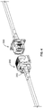
Fig. 1 shows a plug and receptacle halves of a prior art EN4165 connector. -
Fig. 2 shows a forward perspective view of a receptacle connector of the present invention with one modular insert installed and a second modular insert in position to be installed. -
Fig. 3 shows a rear perspective view of a plug connector of the present invention with one modular insert installed and another in position to be installed. -
Fig. 4 shows the receptacle connector ofFig. 2 and the plug connector ofFig. 3 in position to be mated. -
Fig. 5A shows a side-view cross-section of the connectors shown inFig. 4 mated. -
Fig. 5B shows a top-view cross-section of the connectors shown inFig. 4 mated. -
Fig. 6A through Fig. 6C show different embodiments of the connector of the present invention with different combinations of modular inserts.FIG. 6A shows connector comprising two essentially identical optical modular inserts.FIG. 6B shows connector comprising an optical modular insert and an electrical modular insert.FIG. 6C shows connector comprising just a single optical modular insert and a blank filler module for future expansion. -
Fig. 7A shows a set of connectors of the present invention with cable control members disclosed in different directions to facilitate the handling of different conductors. -
Fig. 7B shows an exploded view of the embodiment ofFig. 7A . -
Fig. 8 shows a set of connectors of the present invention with cable control members directing optical and electrical conductors in different directions as they leave the connector. - Referring to
Figs. 2 and 3 , one embodiment of the receptacle and plugconnectors connector shell 201 having acavity 202 configured to receive a single conventional insert having one or more contacts (see,e.g. insert 102 havingcontacts 103 as shown inFig. 1 ). The conventional insert has a conventional form factor. As used herein, the form factor of an insert is defined as its periphery when viewed axially. The connector of the present invention has one or moremodular inserts 203. Each modular insert having a reduced form factor of 1/x of the conventional form factor, such that the cavity is capable of receiving x number of the modular inserts. Each modular insert has at least ahousing 204 having a front and rear orientation, an interior 507 (seeFig. 5b ), and afront opening 205 and arear opening 206. The modular insert also has aninterface 207 disposed in the front opening, and the interface presents one ormore conductors 220. The conductors extend from the interface rearward through the rear opening and into ajacketed cable 208, which may be round or oval or other configuration depending on application. The modular insert also comprises a crimp portion 209 (see alsoFig. 5A ) rearward of therear opening 206. The jacketed cable is secured to the crimp portion. One ormore seals rear opening - These features are described in greater detail below and in connection with selected alternative embodiments. Although the EN416 insert is illustrated in this disclosure, it should be understood that other connector types are possible. Indeed, as mentioned above, there are a variety of ruggedized connectors having cavities for inserts, including, for example, EN 4165, MIL-C-38999,
ARINC 600, EN 3545, EN 4644, plus others. Indeed, it is anticipated that the modular inserts disclosed herein can be used in a variety of different ruggedized connectors. - The modular inserts of the present invention facilitate a variety of different connector configurations. As described above, the modular inserts of the present invention are a mere fraction of the form factor of a conventional insert. For example, an insert for a EN4165 cavity has a form factor of approximately 14.4 mm x 12.7 mm. These are well known standardized form factors. The modular insert of the present invention is a fraction (1/x) of this form factor. The fraction 1/x can vary, and generally ranges from ½ to ¼. As the fraction decreases, the modular inserts may become so small that they may be less desirable. In one embodiment, x is 2 such than each modular insert is essentially half of the form factor of a traditional insert. Although this disclosure considers x=2, it should be understood that other embodiments are possible.
- In one embodiment, the connector has first and second modular inserts. These modular inserts can be the same or they can be different. For example, referring to
Fig. 6A through Fig. 6C different modular inserts configurations are shown. For example, inFig. 6A ,connector 600a comprises two essentially identical opticalmodular inserts Fig. 6B ,connector 600b comprises an opticalmodular insert 611 and an electricalmodular insert 612. InFig. 6C ,connector 600c comprises just a single opticalmodular insert 621 whilespace 622 is left open. Still other embodiments will be obvious to those who have skill in the art in light of this disclosure. Because the modular inserts of the present invention can be configured in different ways within a given cavity, there is no need for specially configured hybrid inserts as are used in the prior art. - As mentioned above one of the benefits of the claimed invention is the integration of the contact with the insert. This avoids the need to prepare special contacts for insertion in the insert. In one embodiment, the optical modular insert is prepared by first terminating the optical cable with a ferrule and then inserting the terminated cable into the insert such that the ferrule seats in the front opening of the insert housing. Such an approach therefore avoids the need to first install the ferrule in a contact. Additionally, this approach avoids the need to custom-machine special ferrules (or otherwise modify standard ferrules) for contact assemblies. Rather, the insert can be configured with an opening to receive a standard ferrule. For example, as shown in
Fig. 2 , theinsert 203 comprises afront opening 205 in which is disposed aninterface 207 which is a conventional ferrule. In this embodiment, the ferrule is a standard off-the-shelf MT ferrule, although it can be any known ferrule, such as, for example, an MT, LMT (lensed MT), MPO, or other multi-fiber ferrule, or, alternatively, single-fiber ferrules, such as the LC or MU ferrules. Those of skill in the art will appreciate that any variety of ferrules can be used in the modular insert of the present invention. Alternatively, the interface may present electrical conductors and comprise metallic contacts as is well known. - In one embodiment, each discrete modular insert is sealed from the environment. This is different from the prior art approach in which the standard form-factor insert was environmentally sealed with the contacts in place. Although this prior art approach has been satisfactory, flexibility to effectively combine electrical and optical conductors may be limited. Those skilled in the art will understand different ways of sealing the discrete inserts in the light of this disclosure. In one embodiment, the seals are provided on the front and back ends of the inserts to insulate the interior of the housing from the environment. For example, referring to
Figs. 2 and5A , afront seal 211 is disclosed between theinterface 207 and theinsert housing 204. Likewise, arear seal 210 is disposed between the housing and arear portion 213. In one embodiment, the termination of thecable 208 to the modular insert is also sealed. Specifically, in one embodiment, aheat shrink material 214 is disposed around the termination of the jacketed cable to the modular insert, essentially over the crimpedportion 209 as shown inFigs 2 andFig. 5A . - Although various embodiments of this jacketed cable seal are within the scope of the invention, in this particular embodiment, a thin heat shrink material is used. The use of a heat shrink material provides for a low profile covering. This has the advantage of having reduced bulk around the cable termination. This is important particularly in certain connector configurations in which there is very little room for bulky grommet-type seals. For example, standard inserts, such as the EN4165 insert, do not provide enough space for a rear grommet seal around the jacketed cable. For example, referring to
Fig. 3 andFig. 4 , it should be clear that when bothmodular inserts 203 are inserted into the housing, there is very little room for anything to extend beyond the form factor of the insert housing. Accordingly, in this embodiment, the jacketed termination seal is within the form factor of thehousing 204. As used herein, the form factor of a housing as defined as its periphery when viewed axially. - Referring to
Fig. 5A and 5B , in one embodiment, the housing is secured within the shell by means of the first and second latch elements. Specifically, the housing comprises afirst latch element 212, which is configured to inter-engage with asecond latch element 551, which is defined on the interior of the shell as shown inFig. 5A . Such latch mechanisms are generally well known and will not be described herein in detail. Suffice to say, however, that in this particular embodiment, the latching mechanism of each modular insert is independently actuatable. In other words each latch can be actuated individually for an individual modular insert thereby facilitating the installation/removal of each modular insert without disturbing the adjacent modular insert(s). Such a feature is important for installation and maintenance. For example, while copper connectors generally involve a swiping action during their mating with another connector, and, thus, stay clean due to the swiping action, the performance of optical connectors generally diminishes with repeated mating due to the accumulation of debris on the front face of the ferrule. Therefore, often it is necessary to remove optical connectors to clean the front face of the ferrule. The modular insert configuration of the present invention facilitates this by allowing optical inserts to be readily removed and cleaned while leaving their copper/metallic counterparts in place. - In one embodiment, the modular insert comprises a cable control member for managing the conductors extending from the modular insert. For example, referring to
Fig. 7 , one embodiment of the cable control element is shown.Fig. 7A shows aconnector 700 having acable control element 701 which is secured to theshell 201 of theconnector 200 by means ofclamp shells Fig. 7B shows as exploded view of this configuration. In one embodiment, thecable control member 701 is curved as shown inFigs. 7A and 7B to direct conductors extending from the modular insert. In this particular embodiment, it is configured as a 90° turn. Alternatively, the turn may be greater than or less than 90°. In one embodiment, thecable control member 701 is capable of being rotated in different positions. For example, inFig. 7A , thecable control member 701 is at the three o'clock position as viewed from the back of themodular insert 700. In one embodiment, thecable control member 701 has afaceted base configuration 705 that allows it to be incrementally rotated in different positions. For example, the cable control member embodiment ofFig. 7A can be rotated in 45° increments, although other embodiments, are possible, e.g., 90°, 60°, 30° increments, etc. - Referring to
Fig. 8 , a set ofconnectors 800 is shown, which includes aplug connector 800a and areceptacle connector 800b. Each connector has twocable control members cable control member 801 forconnector 800a is disposed at the three o'clock position, while thecable control member 802 is disposed at the nine o'clock position. As mentioned above, these positions are given from the perspective of viewing the connector from behind. Such a configuration has a number of benefits. For example, as shown inFig. 8 ,cable control member 801 directs thecopper conductors 803 in one direction and thecable control member 802 directs the jacketedoptical fiber 804 in a different direction. Indeed, by configuring the two cable control members at the three and nine o'clock positions respectively, the different conductors diverge at 180° . Such an embodiment may be preferred in managing different conductors as often they need to be run in different directions and to generally be treated differently. (For example, optical fiber have a minimum bend radius which must be observed at all times while copper conductors do not have such a limitation.)
Claims (15)
- A connector (200) comprising:a shell (201) having a cavity (202) configured to receive a single conventional insert having one or more contacts, said conventional insert having a conventional form factor;one or more modular inserts (203), each modular insert (203) having a reduced form factor of 1/x of said conventional form factor, such that said cavity (202) is capable of receiving x number of said modular inserts (203);said each modular insert (203) having at least:a housing (204) having a front and rear orientation, an interior, and a front opening (205) and a rear opening (206),an interface (207) disposed in said front opening (205), said interface (207) presenting one or more conductors (220), said conductors (220) extending from said interface (207) rearward through said rear opening (206) and into a jacketed cable (208),a crimp portion (209) rearward of said rear opening (206), said jacketed cable (208) being secured to said crimp portion (209),one or more seals (211, 214) sealing said front (205) and rear (206) opening such that said interior of said housing (204) is sealed from environment.
- The connector (200) of claim 1, wherein said one or more seals comprises a front seal (211) between said interface (207) and said housing (204).
- The connector (200) of claim 1, wherein said each modular insert (203) also comprises a rear portion (213) disposed in said rear opening (206), wherein said one or more seals comprises a rear seal (214) between said housing (204) and said rear portion (213).
- The connector (200) of any preceding claim, wherein said one or more seals comprises a heat shrink material (214) over a portion of said jacketed cable (208) crimped to said crimp portion (209).
- The connector of any preceding claim, further comprising a cable control (701) disposed rearward of said crimp portion (209).
- The connector of claim 5, wherein said cable control (701) is configured as a bend in a certain position.
- The connector (800a, 800b) of claim 6, wherein said connector (800a, 800b) comprises a plurality of modular inserts, and said cable control (801, 802) of each said modular insert is configured in a different position.
- The connector (800a, 800b) of claim 7, wherein said positions are at 45° increments.
- The connector (800a, 800b) of claim 8, wherein said plurality of modular inserts comprises a first and second modular insert, and said cable control (801) of said first modular insert is at a 3 o'clock position, and said cable control (802) of said second modular insert is at a 9 o'clock position.
- The connector (600b) of any of claims 1 to 8, comprising first and second said modular inserts (611, 612) wherein one (611) of said first or second modular inserts, comprises optical conductors, and the other (612) comprises metallic conductors.
- The connector (600) of any preceding claim, wherein x is 2.
- The connector (600) of claim 11, wherein said one or more modular inserts (611, 612) comprises first (611) and second (612) modular inserts.
- The connector (600) of claim 12, wherein said first (611) and second (612) modular inserts are different.
- The connector (600) of claim 13, wherein said first modular insert (611) comprises optical conductors and said second modular insert (612) comprises electrical conductors.
- The connector of any preceding claim, wherein said housing (204) comprises at least one first latch element (212) to latch to a corresponding second latch element (551) defined in said cavity (202) of said shell (201).
Applications Claiming Priority (1)
| Application Number | Priority Date | Filing Date | Title |
|---|---|---|---|
| US15/876,986 US10234635B1 (en) | 2018-01-22 | 2018-01-22 | Modular insert assembly |
Publications (2)
| Publication Number | Publication Date |
|---|---|
| EP3514589A1 true EP3514589A1 (en) | 2019-07-24 |
| EP3514589B1 EP3514589B1 (en) | 2023-10-11 |
Family
ID=65200651
Family Applications (1)
| Application Number | Title | Priority Date | Filing Date |
|---|---|---|---|
| EP19153082.3A Active EP3514589B1 (en) | 2018-01-22 | 2019-01-22 | Modular insert assembly |
Country Status (2)
| Country | Link |
|---|---|
| US (1) | US10234635B1 (en) |
| EP (1) | EP3514589B1 (en) |
Cited By (2)
| Publication number | Priority date | Publication date | Assignee | Title |
|---|---|---|---|---|
| EP3869249A1 (en) * | 2020-02-20 | 2021-08-25 | Connecteurs Electriques Deutsch | Optical connector device |
| US12650560B2 (en) | 2022-09-28 | 2026-06-09 | Corning Research & Development Corporation | Fiber optic connectors having one or more optical terminals |
Families Citing this family (6)
| Publication number | Priority date | Publication date | Assignee | Title |
|---|---|---|---|---|
| DE102018113365A1 (en) * | 2018-06-05 | 2019-12-05 | Rosenberger Hochfrequenztechnik Gmbh & Co. Kg | Modular connector system |
| FR3100619A1 (en) * | 2019-09-05 | 2021-03-12 | Souriau | Assembly for the assembly of optical fibers with at least two pairs of MPO contacts |
| IT202000025582A1 (en) | 2020-10-28 | 2022-04-28 | Prysmian Spa | A HYBRID OPTICAL AND POWER DISTRIBUTION BOX |
| US11493712B2 (en) * | 2021-04-06 | 2022-11-08 | Dell Products L.P. | Hybrid port to legacy port converter |
| CN116632585A (en) * | 2023-07-20 | 2023-08-22 | 深圳市格瑞达电力连接器件有限公司 | AGV connector |
| WO2026048161A1 (en) * | 2024-08-30 | 2026-03-05 | 株式会社フジクラ | In-vehicle optical connector unit |
Citations (3)
| Publication number | Priority date | Publication date | Assignee | Title |
|---|---|---|---|---|
| WO2013122865A1 (en) * | 2012-02-16 | 2013-08-22 | Tyco Electronics Corporation | Multi- channel optical connector with inserts |
| US20150260936A1 (en) * | 2014-01-31 | 2015-09-17 | Senko Advanced Components, Inc. | Integrated fiber optic cable fan-out connector |
| WO2016007491A1 (en) * | 2014-07-07 | 2016-01-14 | Adc Telecommunications, Inc. | Optical ferrule for multi-fiber cable and hardened multi-fiber optic connector therefore |
Family Cites Families (4)
| Publication number | Priority date | Publication date | Assignee | Title |
|---|---|---|---|---|
| DE202006011910U1 (en) * | 2005-11-09 | 2007-03-22 | Weidmüller Interface GmbH & Co. KG | Adapter for receiving a plug part |
| US9465171B2 (en) * | 2014-06-10 | 2016-10-11 | Tyco Electronics Corporation | Short optical terminus |
| US9755382B2 (en) * | 2015-03-13 | 2017-09-05 | Senko Advanced Components, Inc. | Connector system with interchangeable connector modules for optical fibers, electrical conductors, or both |
| US20170153399A1 (en) * | 2015-11-30 | 2017-06-01 | Corning Optical Communications LLC | Modular interface converter for fiber optic cassettes and modules |
-
2018
- 2018-01-22 US US15/876,986 patent/US10234635B1/en active Active
-
2019
- 2019-01-22 EP EP19153082.3A patent/EP3514589B1/en active Active
Patent Citations (3)
| Publication number | Priority date | Publication date | Assignee | Title |
|---|---|---|---|---|
| WO2013122865A1 (en) * | 2012-02-16 | 2013-08-22 | Tyco Electronics Corporation | Multi- channel optical connector with inserts |
| US20150260936A1 (en) * | 2014-01-31 | 2015-09-17 | Senko Advanced Components, Inc. | Integrated fiber optic cable fan-out connector |
| WO2016007491A1 (en) * | 2014-07-07 | 2016-01-14 | Adc Telecommunications, Inc. | Optical ferrule for multi-fiber cable and hardened multi-fiber optic connector therefore |
Cited By (3)
| Publication number | Priority date | Publication date | Assignee | Title |
|---|---|---|---|---|
| EP3869249A1 (en) * | 2020-02-20 | 2021-08-25 | Connecteurs Electriques Deutsch | Optical connector device |
| US11460645B2 (en) | 2020-02-20 | 2022-10-04 | Tyco Electronics Uk Ltd. | Optical connector device |
| US12650560B2 (en) | 2022-09-28 | 2026-06-09 | Corning Research & Development Corporation | Fiber optic connectors having one or more optical terminals |
Also Published As
| Publication number | Publication date |
|---|---|
| EP3514589B1 (en) | 2023-10-11 |
| US10234635B1 (en) | 2019-03-19 |
Similar Documents
| Publication | Publication Date | Title |
|---|---|---|
| EP3514589B1 (en) | Modular insert assembly | |
| US11280972B2 (en) | Ultra-small form factor optical connectors used as part of a reconfigurable outer housing | |
| EP2828696B1 (en) | Simplified fiber optic connectors having lenses and method for making the same | |
| KR100248970B1 (en) | Adapter Assembly for Fiber Optic Connectors | |
| EP2904441B1 (en) | Flexible optical circuit | |
| EP4136488A1 (en) | An interconnect system and methods of installing the same | |
| US10996406B2 (en) | Multichannel fiber optic connector, adapter, and contact retention method | |
| KR20210031791A (en) | Narrow width adapters and connectors with modular latching arm | |
| EP3167321B1 (en) | Optical ferrule for multi-fiber cable and hardened multi-fiber optic connector therefore | |
| PL115935B1 (en) | Optical fibre cable connector | |
| US20110085764A1 (en) | Modular optical multiple plug-type connector | |
| GB2357857A (en) | Connector having pivotably accommodated optic fibre ferrule | |
| US11726286B2 (en) | Fiber optic cable connector and adapter housing | |
| US20230161112A1 (en) | Fiber optic terminal having one or more connection ports for receiving fiber optic connectors having a latching trigger | |
| US11092760B2 (en) | Anti-jam alignment sleeve holder or connector housing for a ferrule assembly | |
| US11385418B2 (en) | Reconfigurable fix-shuffled waveguides with modular simplex ferrules | |
| EP1298470B1 (en) | Optical connector system | |
| EP4394466A1 (en) | Multi-cavity optical connector with cable management | |
| US20250130377A1 (en) | Multi-fiber connector structurally configured to provide a reduced footprint and cable volume | |
| US20170139139A1 (en) | Field-installable fiber optic connectors and related cable assemblies |
Legal Events
| Date | Code | Title | Description |
|---|---|---|---|
| PUAI | Public reference made under article 153(3) epc to a published international application that has entered the european phase |
Free format text: ORIGINAL CODE: 0009012 |
|
| STAA | Information on the status of an ep patent application or granted ep patent |
Free format text: STATUS: THE APPLICATION HAS BEEN PUBLISHED |
|
| AK | Designated contracting states |
Kind code of ref document: A1 Designated state(s): AL AT BE BG CH CY CZ DE DK EE ES FI FR GB GR HR HU IE IS IT LI LT LU LV MC MK MT NL NO PL PT RO RS SE SI SK SM TR |
|
| AX | Request for extension of the european patent |
Extension state: BA ME |
|
| STAA | Information on the status of an ep patent application or granted ep patent |
Free format text: STATUS: REQUEST FOR EXAMINATION WAS MADE |
|
| 17P | Request for examination filed |
Effective date: 20200122 |
|
| RBV | Designated contracting states (corrected) |
Designated state(s): AL AT BE BG CH CY CZ DE DK EE ES FI FR GB GR HR HU IE IS IT LI LT LU LV MC MK MT NL NO PL PT RO RS SE SI SK SM TR |
|
| STAA | Information on the status of an ep patent application or granted ep patent |
Free format text: STATUS: EXAMINATION IS IN PROGRESS |
|
| 17Q | First examination report despatched |
Effective date: 20210419 |
|
| GRAP | Despatch of communication of intention to grant a patent |
Free format text: ORIGINAL CODE: EPIDOSNIGR1 |
|
| STAA | Information on the status of an ep patent application or granted ep patent |
Free format text: STATUS: GRANT OF PATENT IS INTENDED |
|
| RIC1 | Information provided on ipc code assigned before grant |
Ipc: G02B 6/38 20060101ALN20230424BHEP Ipc: G02B 6/36 20060101AFI20230424BHEP |
|
| INTG | Intention to grant announced |
Effective date: 20230515 |
|
| GRAS | Grant fee paid |
Free format text: ORIGINAL CODE: EPIDOSNIGR3 |
|
| GRAA | (expected) grant |
Free format text: ORIGINAL CODE: 0009210 |
|
| STAA | Information on the status of an ep patent application or granted ep patent |
Free format text: STATUS: THE PATENT HAS BEEN GRANTED |
|
| RAP1 | Party data changed (applicant data changed or rights of an application transferred) |
Owner name: TE CONNECTIVITY SOLUTIONS GMBH |
|
| AK | Designated contracting states |
Kind code of ref document: B1 Designated state(s): AL AT BE BG CH CY CZ DE DK EE ES FI FR GB GR HR HU IE IS IT LI LT LU LV MC MK MT NL NO PL PT RO RS SE SI SK SM TR |
|
| REG | Reference to a national code |
Ref country code: GB Ref legal event code: FG4D |
|
| REG | Reference to a national code |
Ref country code: CH Ref legal event code: EP |
|
| REG | Reference to a national code |
Ref country code: DE Ref legal event code: R096 Ref document number: 602019038979 Country of ref document: DE |
|
| REG | Reference to a national code |
Ref country code: IE Ref legal event code: FG4D |
|
| REG | Reference to a national code |
Ref country code: LT Ref legal event code: MG9D |
|
| REG | Reference to a national code |
Ref country code: NL Ref legal event code: MP Effective date: 20231011 |
|
| REG | Reference to a national code |
Ref country code: AT Ref legal event code: MK05 Ref document number: 1620785 Country of ref document: AT Kind code of ref document: T Effective date: 20231011 |
|
| PG25 | Lapsed in a contracting state [announced via postgrant information from national office to epo] |
Ref country code: NL Free format text: LAPSE BECAUSE OF FAILURE TO SUBMIT A TRANSLATION OF THE DESCRIPTION OR TO PAY THE FEE WITHIN THE PRESCRIBED TIME-LIMIT Effective date: 20231011 |
|
| PG25 | Lapsed in a contracting state [announced via postgrant information from national office to epo] |
Ref country code: GR Free format text: LAPSE BECAUSE OF FAILURE TO SUBMIT A TRANSLATION OF THE DESCRIPTION OR TO PAY THE FEE WITHIN THE PRESCRIBED TIME-LIMIT Effective date: 20240112 |
|
| PG25 | Lapsed in a contracting state [announced via postgrant information from national office to epo] |
Ref country code: IS Free format text: LAPSE BECAUSE OF FAILURE TO SUBMIT A TRANSLATION OF THE DESCRIPTION OR TO PAY THE FEE WITHIN THE PRESCRIBED TIME-LIMIT Effective date: 20240211 |
|
| PG25 | Lapsed in a contracting state [announced via postgrant information from national office to epo] |
Ref country code: LT Free format text: LAPSE BECAUSE OF FAILURE TO SUBMIT A TRANSLATION OF THE DESCRIPTION OR TO PAY THE FEE WITHIN THE PRESCRIBED TIME-LIMIT Effective date: 20231011 |
|
| PG25 | Lapsed in a contracting state [announced via postgrant information from national office to epo] |
Ref country code: AT Free format text: LAPSE BECAUSE OF FAILURE TO SUBMIT A TRANSLATION OF THE DESCRIPTION OR TO PAY THE FEE WITHIN THE PRESCRIBED TIME-LIMIT Effective date: 20231011 |
|
| PG25 | Lapsed in a contracting state [announced via postgrant information from national office to epo] |
Ref country code: ES Free format text: LAPSE BECAUSE OF FAILURE TO SUBMIT A TRANSLATION OF THE DESCRIPTION OR TO PAY THE FEE WITHIN THE PRESCRIBED TIME-LIMIT Effective date: 20231011 |
|
| PG25 | Lapsed in a contracting state [announced via postgrant information from national office to epo] |
Ref country code: LT Free format text: LAPSE BECAUSE OF FAILURE TO SUBMIT A TRANSLATION OF THE DESCRIPTION OR TO PAY THE FEE WITHIN THE PRESCRIBED TIME-LIMIT Effective date: 20231011 Ref country code: IS Free format text: LAPSE BECAUSE OF FAILURE TO SUBMIT A TRANSLATION OF THE DESCRIPTION OR TO PAY THE FEE WITHIN THE PRESCRIBED TIME-LIMIT Effective date: 20240211 Ref country code: GR Free format text: LAPSE BECAUSE OF FAILURE TO SUBMIT A TRANSLATION OF THE DESCRIPTION OR TO PAY THE FEE WITHIN THE PRESCRIBED TIME-LIMIT Effective date: 20240112 Ref country code: ES Free format text: LAPSE BECAUSE OF FAILURE TO SUBMIT A TRANSLATION OF THE DESCRIPTION OR TO PAY THE FEE WITHIN THE PRESCRIBED TIME-LIMIT Effective date: 20231011 Ref country code: BG Free format text: LAPSE BECAUSE OF FAILURE TO SUBMIT A TRANSLATION OF THE DESCRIPTION OR TO PAY THE FEE WITHIN THE PRESCRIBED TIME-LIMIT Effective date: 20240111 Ref country code: AT Free format text: LAPSE BECAUSE OF FAILURE TO SUBMIT A TRANSLATION OF THE DESCRIPTION OR TO PAY THE FEE WITHIN THE PRESCRIBED TIME-LIMIT Effective date: 20231011 Ref country code: PT Free format text: LAPSE BECAUSE OF FAILURE TO SUBMIT A TRANSLATION OF THE DESCRIPTION OR TO PAY THE FEE WITHIN THE PRESCRIBED TIME-LIMIT Effective date: 20240212 |
|
| PG25 | Lapsed in a contracting state [announced via postgrant information from national office to epo] |
Ref country code: SE Free format text: LAPSE BECAUSE OF FAILURE TO SUBMIT A TRANSLATION OF THE DESCRIPTION OR TO PAY THE FEE WITHIN THE PRESCRIBED TIME-LIMIT Effective date: 20231011 Ref country code: RS Free format text: LAPSE BECAUSE OF FAILURE TO SUBMIT A TRANSLATION OF THE DESCRIPTION OR TO PAY THE FEE WITHIN THE PRESCRIBED TIME-LIMIT Effective date: 20231011 Ref country code: PL Free format text: LAPSE BECAUSE OF FAILURE TO SUBMIT A TRANSLATION OF THE DESCRIPTION OR TO PAY THE FEE WITHIN THE PRESCRIBED TIME-LIMIT Effective date: 20231011 Ref country code: NO Free format text: LAPSE BECAUSE OF FAILURE TO SUBMIT A TRANSLATION OF THE DESCRIPTION OR TO PAY THE FEE WITHIN THE PRESCRIBED TIME-LIMIT Effective date: 20240111 Ref country code: LV Free format text: LAPSE BECAUSE OF FAILURE TO SUBMIT A TRANSLATION OF THE DESCRIPTION OR TO PAY THE FEE WITHIN THE PRESCRIBED TIME-LIMIT Effective date: 20231011 Ref country code: HR Free format text: LAPSE BECAUSE OF FAILURE TO SUBMIT A TRANSLATION OF THE DESCRIPTION OR TO PAY THE FEE WITHIN THE PRESCRIBED TIME-LIMIT Effective date: 20231011 |
|
| PG25 | Lapsed in a contracting state [announced via postgrant information from national office to epo] |
Ref country code: DK Free format text: LAPSE BECAUSE OF FAILURE TO SUBMIT A TRANSLATION OF THE DESCRIPTION OR TO PAY THE FEE WITHIN THE PRESCRIBED TIME-LIMIT Effective date: 20231011 |
|
| REG | Reference to a national code |
Ref country code: DE Ref legal event code: R097 Ref document number: 602019038979 Country of ref document: DE |
|
| PG25 | Lapsed in a contracting state [announced via postgrant information from national office to epo] |
Ref country code: CZ Free format text: LAPSE BECAUSE OF FAILURE TO SUBMIT A TRANSLATION OF THE DESCRIPTION OR TO PAY THE FEE WITHIN THE PRESCRIBED TIME-LIMIT Effective date: 20231011 |
|
| PG25 | Lapsed in a contracting state [announced via postgrant information from national office to epo] |
Ref country code: SK Free format text: LAPSE BECAUSE OF FAILURE TO SUBMIT A TRANSLATION OF THE DESCRIPTION OR TO PAY THE FEE WITHIN THE PRESCRIBED TIME-LIMIT Effective date: 20231011 |
|
| PG25 | Lapsed in a contracting state [announced via postgrant information from national office to epo] |
Ref country code: SM Free format text: LAPSE BECAUSE OF FAILURE TO SUBMIT A TRANSLATION OF THE DESCRIPTION OR TO PAY THE FEE WITHIN THE PRESCRIBED TIME-LIMIT Effective date: 20231011 Ref country code: SK Free format text: LAPSE BECAUSE OF FAILURE TO SUBMIT A TRANSLATION OF THE DESCRIPTION OR TO PAY THE FEE WITHIN THE PRESCRIBED TIME-LIMIT Effective date: 20231011 Ref country code: RO Free format text: LAPSE BECAUSE OF FAILURE TO SUBMIT A TRANSLATION OF THE DESCRIPTION OR TO PAY THE FEE WITHIN THE PRESCRIBED TIME-LIMIT Effective date: 20231011 Ref country code: IT Free format text: LAPSE BECAUSE OF FAILURE TO SUBMIT A TRANSLATION OF THE DESCRIPTION OR TO PAY THE FEE WITHIN THE PRESCRIBED TIME-LIMIT Effective date: 20231011 Ref country code: EE Free format text: LAPSE BECAUSE OF FAILURE TO SUBMIT A TRANSLATION OF THE DESCRIPTION OR TO PAY THE FEE WITHIN THE PRESCRIBED TIME-LIMIT Effective date: 20231011 Ref country code: DK Free format text: LAPSE BECAUSE OF FAILURE TO SUBMIT A TRANSLATION OF THE DESCRIPTION OR TO PAY THE FEE WITHIN THE PRESCRIBED TIME-LIMIT Effective date: 20231011 Ref country code: CZ Free format text: LAPSE BECAUSE OF FAILURE TO SUBMIT A TRANSLATION OF THE DESCRIPTION OR TO PAY THE FEE WITHIN THE PRESCRIBED TIME-LIMIT Effective date: 20231011 |
|
| PLBE | No opposition filed within time limit |
Free format text: ORIGINAL CODE: 0009261 |
|
| STAA | Information on the status of an ep patent application or granted ep patent |
Free format text: STATUS: NO OPPOSITION FILED WITHIN TIME LIMIT |
|
| PG25 | Lapsed in a contracting state [announced via postgrant information from national office to epo] |
Ref country code: MC Free format text: LAPSE BECAUSE OF FAILURE TO SUBMIT A TRANSLATION OF THE DESCRIPTION OR TO PAY THE FEE WITHIN THE PRESCRIBED TIME-LIMIT Effective date: 20231011 |
|
| PG25 | Lapsed in a contracting state [announced via postgrant information from national office to epo] |
Ref country code: MC Free format text: LAPSE BECAUSE OF FAILURE TO SUBMIT A TRANSLATION OF THE DESCRIPTION OR TO PAY THE FEE WITHIN THE PRESCRIBED TIME-LIMIT Effective date: 20231011 |
|
| REG | Reference to a national code |
Ref country code: CH Ref legal event code: PL |
|
| PG25 | Lapsed in a contracting state [announced via postgrant information from national office to epo] |
Ref country code: LU Free format text: LAPSE BECAUSE OF NON-PAYMENT OF DUE FEES Effective date: 20240122 |
|
| 26N | No opposition filed |
Effective date: 20240712 |
|
| PG25 | Lapsed in a contracting state [announced via postgrant information from national office to epo] |
Ref country code: LU Free format text: LAPSE BECAUSE OF NON-PAYMENT OF DUE FEES Effective date: 20240122 |
|
| PG25 | Lapsed in a contracting state [announced via postgrant information from national office to epo] |
Ref country code: BE Free format text: LAPSE BECAUSE OF NON-PAYMENT OF DUE FEES Effective date: 20240131 |
|
| PG25 | Lapsed in a contracting state [announced via postgrant information from national office to epo] |
Ref country code: CH Free format text: LAPSE BECAUSE OF NON-PAYMENT OF DUE FEES Effective date: 20240131 |
|
| PG25 | Lapsed in a contracting state [announced via postgrant information from national office to epo] |
Ref country code: SI Free format text: LAPSE BECAUSE OF FAILURE TO SUBMIT A TRANSLATION OF THE DESCRIPTION OR TO PAY THE FEE WITHIN THE PRESCRIBED TIME-LIMIT Effective date: 20231011 |
|
| PG25 | Lapsed in a contracting state [announced via postgrant information from national office to epo] |
Ref country code: SI Free format text: LAPSE BECAUSE OF FAILURE TO SUBMIT A TRANSLATION OF THE DESCRIPTION OR TO PAY THE FEE WITHIN THE PRESCRIBED TIME-LIMIT Effective date: 20231011 Ref country code: CH Free format text: LAPSE BECAUSE OF NON-PAYMENT OF DUE FEES Effective date: 20240131 Ref country code: BE Free format text: LAPSE BECAUSE OF NON-PAYMENT OF DUE FEES Effective date: 20240131 |
|
| REG | Reference to a national code |
Ref country code: BE Ref legal event code: MM Effective date: 20240131 |
|
| PG25 | Lapsed in a contracting state [announced via postgrant information from national office to epo] |
Ref country code: IE Free format text: LAPSE BECAUSE OF NON-PAYMENT OF DUE FEES Effective date: 20240122 |
|
| PG25 | Lapsed in a contracting state [announced via postgrant information from national office to epo] |
Ref country code: IE Free format text: LAPSE BECAUSE OF NON-PAYMENT OF DUE FEES Effective date: 20240122 |
|
| PG25 | Lapsed in a contracting state [announced via postgrant information from national office to epo] |
Ref country code: CY Free format text: LAPSE BECAUSE OF FAILURE TO SUBMIT A TRANSLATION OF THE DESCRIPTION OR TO PAY THE FEE WITHIN THE PRESCRIBED TIME-LIMIT; INVALID AB INITIO Effective date: 20190122 |
|
| PG25 | Lapsed in a contracting state [announced via postgrant information from national office to epo] |
Ref country code: HU Free format text: LAPSE BECAUSE OF FAILURE TO SUBMIT A TRANSLATION OF THE DESCRIPTION OR TO PAY THE FEE WITHIN THE PRESCRIBED TIME-LIMIT; INVALID AB INITIO Effective date: 20190122 |
|
| PG25 | Lapsed in a contracting state [announced via postgrant information from national office to epo] |
Ref country code: FI Free format text: LAPSE BECAUSE OF FAILURE TO SUBMIT A TRANSLATION OF THE DESCRIPTION OR TO PAY THE FEE WITHIN THE PRESCRIBED TIME-LIMIT Effective date: 20231011 |
|
| PG25 | Lapsed in a contracting state [announced via postgrant information from national office to epo] |
Ref country code: TR Free format text: LAPSE BECAUSE OF FAILURE TO SUBMIT A TRANSLATION OF THE DESCRIPTION OR TO PAY THE FEE WITHIN THE PRESCRIBED TIME-LIMIT Effective date: 20231011 |
|
| PGFP | Annual fee paid to national office [announced via postgrant information from national office to epo] |
Ref country code: GB Payment date: 20251204 Year of fee payment: 8 |
|
| PGFP | Annual fee paid to national office [announced via postgrant information from national office to epo] |
Ref country code: FR Payment date: 20251208 Year of fee payment: 8 |
|
| PGFP | Annual fee paid to national office [announced via postgrant information from national office to epo] |
Ref country code: DE Payment date: 20251203 Year of fee payment: 8 |