EP3514476B1 - Holster mount with adjustable drop and cant - Google Patents
Holster mount with adjustable drop and cant Download PDFInfo
- Publication number
- EP3514476B1 EP3514476B1 EP18155876.8A EP18155876A EP3514476B1 EP 3514476 B1 EP3514476 B1 EP 3514476B1 EP 18155876 A EP18155876 A EP 18155876A EP 3514476 B1 EP3514476 B1 EP 3514476B1
- Authority
- EP
- European Patent Office
- Prior art keywords
- holster
- slider
- assembly
- track
- mount
- Prior art date
- Legal status (The legal status is an assumption and is not a legal conclusion. Google has not performed a legal analysis and makes no representation as to the accuracy of the status listed.)
- Active
Links
Images




Classifications
-
- F—MECHANICAL ENGINEERING; LIGHTING; HEATING; WEAPONS; BLASTING
- F41—WEAPONS
- F41C—SMALLARMS, e.g. PISTOLS, RIFLES; ACCESSORIES THEREFOR
- F41C33/00—Means for wearing or carrying smallarms
- F41C33/02—Holsters, i.e. cases for pistols having means for being carried or worn, e.g. at the belt or under the arm
- F41C33/04—Special attachments therefor
- F41C33/041—Special attachments therefor for connecting a holster to a belt, webbing or other object
- F41C33/045—Special attachments therefor for connecting a holster to a belt, webbing or other object for connection in more than one rotational position around an axle, e.g. by using a rotatable connection
-
- F—MECHANICAL ENGINEERING; LIGHTING; HEATING; WEAPONS; BLASTING
- F41—WEAPONS
- F41C—SMALLARMS, e.g. PISTOLS, RIFLES; ACCESSORIES THEREFOR
- F41C33/00—Means for wearing or carrying smallarms
- F41C33/02—Holsters, i.e. cases for pistols having means for being carried or worn, e.g. at the belt or under the arm
- F41C33/0209—Pouch or pocket like containers for small arms covering all or most of the small arm
-
- F—MECHANICAL ENGINEERING; LIGHTING; HEATING; WEAPONS; BLASTING
- F41—WEAPONS
- F41C—SMALLARMS, e.g. PISTOLS, RIFLES; ACCESSORIES THEREFOR
- F41C33/00—Means for wearing or carrying smallarms
- F41C33/02—Holsters, i.e. cases for pistols having means for being carried or worn, e.g. at the belt or under the arm
- F41C33/04—Special attachments therefor
- F41C33/041—Special attachments therefor for connecting a holster to a belt, webbing or other object
- F41C33/043—Special attachments therefor for connecting a holster to a belt, webbing or other object for connection in more than one transversal position
Definitions
- This invention relates to an apparatus for adjustably supporting a holster on a user's belt.
- the invention relates to an apparatus that enables a user to place the holster in a first position of drop and/or cant relative to the user while seated in a car or other vehicle, and then place the holster in a second, different position of drop and/or cant relative to the user after exiting the vehicle.
- a holster mounts the handgun at a height near the waist or hip of the user and, in some adjustable holsters, in a selected position of cant. But when the holster is in this "use" position, and the user thereafter sits down in a vehicle, the holster and gun are awkwardly positioned.
- AU 649945 B3 describes a holster for a gun comprising a pouch for receiving a gun. The pouch is mounted on a belt-receiving member that has an elongate slot.
- the pouch is mounted to the belt-receiving member by a means of a fastening passed through the elongate slot.
- the fastening is able to be selectively released to allow the pouch to be moved axially relative to the belt-receiving member to a desired relative location by moving the fastening along the slot and then tightening the fastening to retain the pouch in the desired relative location.
- the pouch is able to rotate about the fastening.
- a holster support assembly for use by a user wearing a belt in accordance with the invention is defined in claim 1.
- Some preferred embodiments of the invention are defined in the dependent claims.
- the present invention relates to a holster support assembly for adjustably supporting a holster on a user.
- the invention is applicable to holster mount assemblies of various configurations.
- Figures 1-10 illustrate a holster support assembly that is a first embodiment of the invention.
- the holster support assembly 10 is usable for supporting a holster, shown schematically at 12, on a user's belt shown partially at 14.
- the holster support assembly 10 includes generally five components, each described below in detail: a belt support 20 that is carried on the user's belt; a slider 70 that is slidable vertically on the belt support; a holster mount 90 that is connected with the slider (to adjust drop) and also is pivotable relative to the slider (to adjust cant); a lock bar 120 for locking the parts in a selected vertical (drop) and rotational (cant) position; and a screw assembly 130 for securing together the other components of the holster support assembly 10.
- the belt support 20 ( Figures 1-3 and 7 ) supports the assembly 10 on the user's belt 14.
- the belt support 20 has an upper end portion 22 that is curved or contoured to fit the curved configuration of the user's torso.
- the upper end portion 22 includes two belt slots 24 for receiving the user's belt 14.
- the belt support 20 can thus be hung from the user's belt 14, and slid (positioned) laterally along the belt, so that the holster assembly 10 is in the desired position adjacent to the user's hip.
- a main body portion 26 of the belt support 20 extends down from the upper end portion 22.
- a laterally central section of the main body portion 26 forms a vertically extending track 30, which comprises two rails 32 on opposite sides of a central slot 34.
- the rails 32a and 32b have a generally planar, plate-like configuration.
- the slider 70 and holster body are movable vertically along the track 30 to adjust the drop of the holster 12.
- the central slot 34 which is also part of the track 30, extends completely through the belt support 20 between the inner and outer side surfaces 42 and 44, respectively, of the belt support.
- the central slot 34 is defined by the two rails 32 that are on opposite sides of the central slot. For each rail 32 its outer side surface is part of the outer side surface 44 of the belt support 20, and its inner side surface is part of the inner side surface 42 of the belt support.
- the central slot 34 has a relatively narrow lower section 50 that is a constant width along its entire length.
- the central slot 34 has an upper section 52 that is significantly wider than the lower section 50 and that has a generally square configuration. As a result, the slot 34 has a generally keyhole-shaped configuration.
- two bump stops 54 At the top of the lower section 50 of the central slot 34, just at the bottom edge of the upper section 52, are located two bump stops 54, one on each rail 32.
- the wall thickness of the track rails 32 (from inside to outside, or left to right as viewed in Figures 9A-9B ) is different, over three different sections of the track 30. Specifically, in a locking section 30a of the track 30, starting at the bottom end of the central slot 34, the rails 32 have a constant, first wall thickness. At the top of the locking section 30a of the track 30, the wall thickness of the rails 32 decreases to form a ramp section 30b of the track that has a tapering second wall thickness. Above the ramp section 30b, in a release section 30c of the track 30, and adjacent to the enlarged upper section 52 of the central slot 34, the rails 32 have a constant reduced third wall thickness that is the same as the thinnest part of the ramp section.
- the central slot 34 is located between and defined by the rails 32, the depth of the slot varies in the same manner as does the wall thickness of the rails. Specifically, the slot 34 is deeper in the locking section 30a of the rails 32, tapers in depth in the ramp section 30b, and is shallowest in the release section 30c.
- the slider 70 is slidable vertically along the track 30 of the belt support 20.
- the belt support 20 has a number of features for helping to set the vertical orientation of the slider 50 on the belt support. Specifically, on one side of the track 30 are formed three notches 56. On the opposite side of the track 30 are four rib segments 58 spaced apart with gaps 60 between them. The notches 56 and the gaps 60 are located along the lower portion (constant wall thickness) 30a of the track 30. The notches 56 are located laterally opposite and thus paired with the gaps 60.
- Each associated pair of notch 56 and gap 60 defines a detent (or locking position) 62 on the belt support.
- an assembly 10 in accordance with the invention could have more than three locking positions 62 or fewer than three locking positions.
- the slider 70 ( Figures 3-4 ) engages with the belt support 20 and supports the holster mount 90 for vertical and rotational (pivotal) movement relative to the belt support.
- the slider 70 is a disc-shaped member having generally planar inner and outer major side surfaces 72 and 74 connected by an annular outer peripheral surface 76.
- the inner major side surface 72 of the slider 70 is engageable with and slidable along the outer major side surface 44 of the belt support 20.
- Several features are present on the inner major side surface 72 of the slider 70.
- the groove 76 extends horizontally for the full width of the slider 70.
- Two detent notches 78 are formed at one position along the length of the groove 76.
- the groove slidably 80 receives the ribs 58 of the belt support. This engagement of the ribs 58 in the groove 80 secures the slider 70 against rotation about the transverse axis 88.
- two generally triangular restraint tabs 89 are disposed along the length of the vertical groove 80, on opposite sides of the groove. The restraint tabs 89, as well as two shorter ribs 92 diametrically opposite the groove 80, assist in maintaining the positioning of the slider 70 on the belt support 20.
- a circular array of wedge-shaped locking teeth 84 On the outer major side surface 74 of the slider 70, facing away from the belt support 20, there is formed a circular array of wedge-shaped locking teeth 84.
- the teeth 84 extend radially outward from a centrally located through hole 86 that defines a transverse axis 88 of the holster assembly 10.
- the holster mount 90 is a member that is configured to directly engage and support the holster 12 itself on the slider. As a result, and as described in detail below, the holster 12, the holster mount 90, and the slider 70 are movable vertically, together, along the track 30 of the belt support 20.
- the holster mount 90 is a plate-like member that in the illustrated embodiment has a generally teardrop-shaped configuration including a wider upper end portion and a narrower lower end portion to accommodate the similar configuration of a typical holster.
- Two holster connection openings 92 are located in the upper end portion of the holster mount 90 and one holster connection opening 92 is provided in the lower end portion of the holster mount.
- the holster connection openings 92 receive fasteners shown schematically at 94 ( Figure 1 ) for securing the holster 12 to the holster mount 90.
- the openings 92 may, as illustrated, be arcuate slots enabling mounting of the holster 12 at different pivotal (rotational) orientations on the holster mount 90.
- the holster mount 90 has a generally flat outer major side surface 96 that is presented outward and that is in abutting engagement with the holster 12 when the holster is secured on the holster mount.
- the holster mount 90 has an opposite inner major side surface 98 that is presented inward toward the user, and toward the slider 70, when the holster mount is connected as part of the holster assembly 10.
- On the inner major side surface of the holster mount 90 is a circular array of radially extending, wedge-shaped locking teeth 100, effectively a mirror image of the array of locking teeth 84 on the slider 70.
- the holster mount 90 has a central opening 102 that is co-axial with the central opening 86 in the slider 70 when the holster assembly 10 is assembled.
- An internally threaded propeller nut or T-nut 104 is secured in the central opening 102 of the holster mount 90, on the outside of the holster mount, to provide an internally threaded location for receiving the assembly screw 132.
- An annular boss 106 extends around the opening 102, on the inner side surface 98 of the holster mount 90.
- An annular spring chamber 108 extends around the boss 106.
- the spring chamber 108 receives a circular compression spring 110.
- the spring 110 acts outwardly between the slider 70 and the holster mount 90, attempting to push them apart.
- the holster 12 is secured to the holster mount 90 in a known manner, such as by the fasteners 94.
- the actual configuration of the holster itself is not critical, and so the holster 12 is shown only in phantom.
- the lock bar 120 is configured as an elongate bar that extends laterally across the track 30 of the belt support 20, at a location captured (inside to outside) between the belt support and the slider 70.
- the lock bar 120 is slidable laterally when in its position between the belt support 20 and the slider 70.
- At one end of the of the lock bar 120 is a manually engageable tab or handle 122 that can be used to pull or push the lock bar across the track 30.
- the lock bar 120 also has projections 124 that are engageable with the detent notches 78 on the slider 70.
- An elongate screw passage 126 extends in a direction along the length of the lock bar 120.
- the screw assembly 130 includes a screw 132 that in the illustrated embodiment is a machine screw having a round head 134 and an externally threaded shank 136.
- the screw 132 is assembled with a plastic washer 138 that is fitted under and around the screw head 134.
- a plate 140 is secured onto the washer 138 by peening over four pins 142 on the washer.
- the washer 138 is slightly smaller than the opening of the release section 52 of the central slot 34, so as to be able to fit through the release section.
- the washer 138 is free floating on the screw 132, that is, the washer and the screw are relatively rotatable.
- the washer 138 has a generally square configuration with rounded corners. One of the four corners of the washer may be different from the other three, for assembly and orientation purposes. Also, the underside of the washer 138 ( Figure 3 ) has two slots 144 that extend halfway up the washer. When the screw assembly 130 is connected in the holster assembly 10, the slots 144 extend from the screw shank 136 in a direction toward the lower section 50 of the central slot 34 in the belt support 20.
- the slider 70 is placed on and engaged with the outer side surface 44 of the belt support 20.
- the vertical ribs 58 on the belt support 20 are received in the vertical groove 80 on the slider 70, this engagement blocks rotation of the slider on the belt support.
- the tabs 89 on the slider 70 also assist in this regard. As a result, the slider 70 is supported on the belt support 20 for vertical sliding movement along the belt support, without rotation.
- the lock bar 120 is placed to extend laterally along the horizontal groove 76 in the slider 70, at a position captured between the slider and the belt support 20.
- the screw slot passage 126 in the lock bar 120 overlies the central opening 86 in the slider 70, and also overlies the central slot 34 in the belt support 20.
- the holster mount 90 is positioned on the slider 70, with the compression spring 110 between them in the spring chamber 108 that extends around the boss 106.
- the screw assembly 130 holds the other pieces together. Specifically, the screw head 134 and the washer 138 are positioned on the inner side surface 42 of the belt support 20.
- the screw shank 136 extends through the central slot 34 in the belt support 20, through the central opening 86 in the slider 70, through the screw passage 126 in the lock bar 120, and into the center of the boss 106 on the holster mount 90.
- the nut 104 is lockingly engaged in the central opening 102 of the holster mount 90, and receives the threaded screw shank 136.
- the parts of the holster assembly 10 are held together securely in the direction along the length of the screw 132.
- the spring 110 acts outwardly between the slider 70 and the holster mount 90, attempting to push them apart in a direction along the transverse axis 88, that is, along the length of the screw 132.
- the screw 132 When the parts are assembled in this manner, it is done with the screw 132 extending through the lower section 50 of the central slot 34 in the belt support 20. In this position, the rails 32 have a relatively large wall thickness and the central slot 34 is relatively deep.
- the screw 132 is tightened down on the holster mount 90 to a point at which there is little or no movement possible between the parts in a direction along the length of the screw 132, the screw 130 and the nut 104 cooperate to hold the holster mount 90 in tight against the slider 70.
- the screw 132 is intentionally not tightened down enough to prevent all vertical movement of the parts along the track 30. Rather, the parts can be moved vertically with the application of a reasonable amount of force, to enable the user to adjust the holster assembly 10. This is because the lock bar 120 ( Fig. 6 ) is thinner at its inner end 125 than at its outer end 123, so that when the lock bar is opened, the parts can be moved easily.
- the radial teeth 84 of the slider 70 are engaged with the radial teeth 100 of the holster mount 90, preventing any rotation of the holster mount and the holster 12, on the belt support 20.
- the holster assembly 10 of the present invention is useful for adjustably supporting the holster 12 on the user's belt 14.
- the user can place the holster 12 in a first position of drop and cant relative to the user while seated in a car or other vehicle, and then place the holster in a second, different position of drop and cant after exiting the vehicle.
- the three locking positions 62 noted above with reference to the belt support 20, provide three different drop heights for the holster 12 on the belt support.
- the holster assembly 10 may come from the manufacturer set in one of the three locking positions 62.
- the user can select and lock in any one of the three available drop heights for use when the user is standing up and wearing the holster assembly 10.
- the cant position (orientation), however, can be changed only when the holster assembly 10 is unlocked, as described below.
- the user withdraws the lock bar 120 to the open position shown in Figure 7 .
- the slider 70 is then free to move vertically along the track 30 of the belt support 20.
- the user applies sufficient manual force to move the holster 12, the holster mount 90, and the slider 70 vertically, to the desired locking position 62.
- the lock bar 120 is then moved back to the closed position shown in Figure 8 .
- the lock bar 120 is securely held vertically by the detents in the belt support 20 that form the locking positions.
- the detent features 124 on the lock bar 120 engage in the notches 78 of the slider 70. This engagement resists movement of the lock bar 120 out of the closed position, ensuring that the drop height of the holster 12 is not inadvertently changed.
- the radial teeth 100 on the holster mount 90 continue to engage the radial teeth 84 on the slider 70.
- This engagement blocks rotation of the holster mount 90 relative to the slider 70.
- the slider 70 cannot rotate on the belt support 20, this engagement also blocks rotation of the holster mount 90 relative to the belt support 20.
- the cant position of the holster 12 is fixed, keeping the holster in a position for the user to quickly draw the weapon.
- the holster mount 90 When the user wants to change the cant position of the holster 12, for example to sit down, the holster mount 90 needs to be rotated relative to the belt support 20 and the slider 70; consequently, the radial teeth 100 on the holster mount must be disengaged from the radial teeth 84 on the slider. To enable this disengagement to happen, the holster mount 90 and the slider 70 must be moved apart (separated) from each other in a direction along the transverse axis 88. This axial separation movement cannot occur when the holster assembly 10 is in or near any of the three locking positions 62, because the screw 130 and the nut 104 cooperate to hold the holster mount 90 in tight against the slider 70.
- the slider 70 is moved upward to the release section 30c of the track 30.
- the user unlocks the lock bar 120, and pulls the holster 12, holster mount 90, slider 70, and screw assembly 130 upward from the locking section 30a of the track 30, past the ramp section 30b of the track, and into the release section 30c of the track.
- This movement is seen in a comparison of Figures 9A and 9B .
- the upward movement of the parts stops when the washer 138 engages the top of the central slot 34. Specifically, when the parts move up far enough, the two bump stops 54 on the rails 32 move into the two slots 144 on the washer 138 and limit (stop) the upward movement of the washer at that point. Thus, the shank 136 of the assembly screw 130 stays in the narrow lower section 52 of the central slot 34.
- the washer 138 is sliding along the inner side surface 42 of the rails 32.
- the slider 70 is sliding along the outer surface 44 of the rails 32.
- the screw/nut combination 132/104 is a fixed length; but when the washer 138 is moved up past the ramp section 30b to the release section 30c, the rails 32 (between the screw head and the washer) are thinner, so there is some open space generated along the length of the screw shank 136, between the washer 134 and the nut 104.
- This open space allows for expansion of the compression spring 110, which all along is acting between the slider 70 and the holster mount 90 to attempt to push them apart transversely.
- the expanding spring 110 pushes the holster mount 90 outward (to the right as viewed in Fig. 9B ).
- the extra space and movement that is provided, by virtue of the thinner rails 32 in the release section 30c, is enough to allow the radial teeth 100 of the holster mount 90 to disengage from the radial teeth 84 of the slider 70.
- the holster mount 90 is then free to rotate relative to the slider 70. The user can change the cant position of the holster mount 90 (and the holster 12) to a more comfortable position for sitting.
- the user When the user thereafter wants to return the holster assembly 10 to the original (standing) position, the user rotates the holster 12 and the holster mount 90 back to the original position, and then pushes the entire assembly down on the belt support 20. As this downward movement occurs, the parts move past the ramp section 30b of the track 30 onto the locking section 30a of the track. The extra space between the washer 138 and the nut 104 is taken up by the increased wall thickness of the rails 32. The holster mount 90 moves back toward the slider 70, compressing the spring 110. The radial teeth 100 of the holster mount 90 engage again with the radial teeth 84 of the slider 70, blocking relative rotational movement between those two parts. The parts can be placed in any one of the available (in this case three) locking positions 62 and can be locked there by restoring the lock bar 120 to the closed position.
- a holster assembly of the present invention can be configured to be supported on a user at a location other than the user's belt.
- a holster assembly of the present invention can be configured to be supported on, for example, a user's vest or jacket.
- the parts of the holster assembly 10 of Fig. 1 are removable from the belt support 20, to be positioned elsewhere.
- the user unlocks the lock bar 120, allowing the slider 70 and the holster mount 90 to be moved upward on the belt support 20.
- the slider 70 is moved up to the release section 30c of the track 30, as described above.
- the upward movement of the slider 70 would normally stop when the washer 138 engages the bump stops 54 as described above. With the application of sufficient force, however, the user can move the parts past the bump stops 54, pushing the holster mount 90 into slider 70 and thus compressing the spring 110, allowing sufficient room for the washer/screw assembly to travel over the bump stops 54.
- the washer 138 and screw head 134 then move into the enlarged upper section 52 of the central slot 34. At that point, the washer 138 and screw head 134 can be moved past the belt support 20, in a direction toward the slider 70 (to the left as viewed in Figures 9A and 9B ), and thus be disconnected from the belt support.
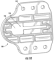
- Fig. 10 illustrates an element 150 that can be used to support those parts on, for example, a user's vest or jacket;
- the element 150 has fastener openings 152 for fastening the element to the garment.
- the element 150 includes a central slot 154 with an enlarged end portion 156 through which the washer 138 and screw head 134 are inserted, in a direction from the opposite (not shown) side of the element. That opposite side of the element 150 includes features to engage the slider 70 and the lock bar 120, as in the assembly 10.
- This particular element 150 does not include the ramp feature that enables changing the cant of the holster 12; rather, this particular element only allows the user to place the holster in a different location on the user's body or garments, or on another element such as a portion of a vehicle or structure. Other elements can have this additional feature, if desired.
Landscapes
- Engineering & Computer Science (AREA)
- General Engineering & Computer Science (AREA)
- Devices For Indicating Variable Information By Combining Individual Elements (AREA)
- Automotive Seat Belt Assembly (AREA)
- Workshop Equipment, Work Benches, Supports, Or Storage Means (AREA)
Description
- This invention relates to an apparatus for adjustably supporting a holster on a user's belt. In particular, the invention relates to an apparatus that enables a user to place the holster in a first position of drop and/or cant relative to the user while seated in a car or other vehicle, and then place the holster in a second, different position of drop and/or cant relative to the user after exiting the vehicle.
- When a user carries a handgun in a holster on the user's belt, and is standing up, the handgun needs to be in a position to enable rapid and accurate drawing of the handgun from the holster. The holster mounts the handgun at a height near the waist or hip of the user and, in some adjustable holsters, in a selected position of cant. But when the holster is in this "use" position, and the user thereafter sits down in a vehicle, the holster and gun are awkwardly positioned.
AU 649945 B3 - A holster support assembly for use by a user wearing a belt in accordance with the invention is defined in claim 1. Some preferred embodiments of the invention are defined in the dependent claims.
- The invention will now be further described by way of example with reference to the accompanying drawings, in which:
-
Fig. 1 is a perspective view of a holster assembly that is a first embodiment of the invention, taken from the outside and shown supporting a holster on a user's belt; -
Fig. 2 is a perspective view of the holster assembly ofFig. 1 , taken from the inside; -
Fig. 3 is an exploded perspective view of the holster assembly ofFig. 1 ; -
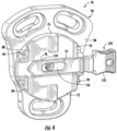
Fig. 4 is a perspective view of part of the holster assembly ofFig. 1 including a holster mount, a slider, and a lock bar; -
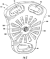
Fig. 5 is a view of the holster mount ofFig. 4 from the opposite side; -
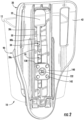
Fig. 6 is a transverse sectional view through the holster assembly ofFig. 1 ; -
Fig. 7 is a perspective view illustrating the belt support with the lock bar in an open or unlocked position; -
Fig. 8 is a view similar toFig. 7 illustrating the belt support with the lock bar in the closed or locked position; -
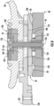
Fig. 9A and 9B are longitudinal sectional views showing the holster assembly in a cant locked position and in a cant released position; and -
Fig. 10 is a perspective view showing an element that can be used to support a holster assembly on a user at a location other than the user's belt. - The present invention relates to a holster support assembly for adjustably supporting a holster on a user. The invention is applicable to holster mount assemblies of various configurations. As representative of the invention,
Figures 1-10 illustrate a holster support assembly that is a first embodiment of the invention. Theholster support assembly 10 is usable for supporting a holster, shown schematically at 12, on a user's belt shown partially at 14. - The
holster support assembly 10 includes generally five components, each described below in detail: abelt support 20 that is carried on the user's belt; aslider 70 that is slidable vertically on the belt support; aholster mount 90 that is connected with the slider (to adjust drop) and also is pivotable relative to the slider (to adjust cant); alock bar 120 for locking the parts in a selected vertical (drop) and rotational (cant) position; and ascrew assembly 130 for securing together the other components of theholster support assembly 10. - The belt support 20 (
Figures 1-3 and7 ) supports theassembly 10 on the user'sbelt 14. Thebelt support 20 has anupper end portion 22 that is curved or contoured to fit the curved configuration of the user's torso. Theupper end portion 22 includes twobelt slots 24 for receiving the user'sbelt 14. Thebelt support 20 can thus be hung from the user'sbelt 14, and slid (positioned) laterally along the belt, so that theholster assembly 10 is in the desired position adjacent to the user's hip. - A
main body portion 26 of thebelt support 20 extends down from theupper end portion 22. A laterally central section of themain body portion 26 forms a vertically extendingtrack 30, which comprises tworails 32 on opposite sides of acentral slot 34. The rails 32a and 32b have a generally planar, plate-like configuration. As described below in detail, theslider 70 and holster body are movable vertically along thetrack 30 to adjust the drop of theholster 12. - The
central slot 34, which is also part of thetrack 30, extends completely through thebelt support 20 between the inner andouter side surfaces central slot 34 is defined by the tworails 32 that are on opposite sides of the central slot. For eachrail 32 its outer side surface is part of theouter side surface 44 of thebelt support 20, and its inner side surface is part of theinner side surface 42 of the belt support. - The
central slot 34 has a relatively narrowlower section 50 that is a constant width along its entire length. Thecentral slot 34 has anupper section 52 that is significantly wider than thelower section 50 and that has a generally square configuration. As a result, theslot 34 has a generally keyhole-shaped configuration. At the top of thelower section 50 of thecentral slot 34, just at the bottom edge of theupper section 52, are located twobump stops 54, one on eachrail 32. - The wall thickness of the track rails 32 (from inside to outside, or left to right as viewed in
Figures 9A-9B ) is different, over three different sections of thetrack 30. Specifically, in alocking section 30a of thetrack 30, starting at the bottom end of thecentral slot 34, therails 32 have a constant, first wall thickness. At the top of thelocking section 30a of thetrack 30, the wall thickness of therails 32 decreases to form aramp section 30b of the track that has a tapering second wall thickness. Above theramp section 30b, in arelease section 30c of thetrack 30, and adjacent to the enlargedupper section 52 of thecentral slot 34, therails 32 have a constant reduced third wall thickness that is the same as the thinnest part of the ramp section. - Because the
central slot 34 is located between and defined by therails 32, the depth of the slot varies in the same manner as does the wall thickness of the rails. Specifically, theslot 34 is deeper in thelocking section 30a of therails 32, tapers in depth in theramp section 30b, and is shallowest in therelease section 30c. - As described below in detail, the
slider 70 is slidable vertically along thetrack 30 of thebelt support 20. In that regard, thebelt support 20 has a number of features for helping to set the vertical orientation of theslider 50 on the belt support. Specifically, on one side of thetrack 30 are formed three notches 56. On the opposite side of thetrack 30 are four rib segments 58 spaced apart with gaps 60 between them. The notches 56 and the gaps 60 are located along the lower portion (constant wall thickness) 30a of thetrack 30. The notches 56 are located laterally opposite and thus paired with the gaps 60. - Each associated pair of notch 56 and gap 60 defines a detent (or locking position) 62 on the belt support. In the illustrated embodiment, there are three vertically spaced locking positions 62a, 62b, 62c. In other embodiments, an
assembly 10 in accordance with the invention could have more than three locking positions 62 or fewer than three locking positions. - The slider 70 (
Figures 3-4 ) engages with thebelt support 20 and supports theholster mount 90 for vertical and rotational (pivotal) movement relative to the belt support. Theslider 70 is a disc-shaped member having generally planar inner and outermajor side surfaces peripheral surface 76. - The inner
major side surface 72 of theslider 70 is engageable with and slidable along the outermajor side surface 44 of thebelt support 20. Several features are present on the innermajor side surface 72 of theslider 70. First, there is a horizontally extendinggroove 76 having dimensions selected to closely receive thelock bar 120 in a manner as described below. Thegroove 76 extends horizontally for the full width of theslider 70. Twodetent notches 78 are formed at one position along the length of thegroove 76. - Second, there is a
vertical groove 80 at one side of theslider 70. When theslider 70 is mounted on thebelt support 20, thegroove slidably 80 receives the ribs 58 of the belt support. This engagement of the ribs 58 in thegroove 80 secures theslider 70 against rotation about thetransverse axis 88. Third, two generally triangular restraint tabs 89 are disposed along the length of thevertical groove 80, on opposite sides of the groove. The restraint tabs 89, as well as twoshorter ribs 92 diametrically opposite thegroove 80, assist in maintaining the positioning of theslider 70 on thebelt support 20. - On the outer
major side surface 74 of theslider 70, facing away from thebelt support 20, there is formed a circular array of wedge-shapedlocking teeth 84. Theteeth 84 extend radially outward from a centrally located throughhole 86 that defines atransverse axis 88 of theholster assembly 10. - The
holster mount 90 is a member that is configured to directly engage and support theholster 12 itself on the slider. As a result, and as described in detail below, theholster 12, theholster mount 90, and theslider 70 are movable vertically, together, along thetrack 30 of thebelt support 20. - The
holster mount 90 is a plate-like member that in the illustrated embodiment has a generally teardrop-shaped configuration including a wider upper end portion and a narrower lower end portion to accommodate the similar configuration of a typical holster. Twoholster connection openings 92 are located in the upper end portion of theholster mount 90 and oneholster connection opening 92 is provided in the lower end portion of the holster mount. Theholster connection openings 92 receive fasteners shown schematically at 94 (Figure 1 ) for securing theholster 12 to theholster mount 90. Theopenings 92 may, as illustrated, be arcuate slots enabling mounting of theholster 12 at different pivotal (rotational) orientations on theholster mount 90. - The
holster mount 90 has a generally flat outermajor side surface 96 that is presented outward and that is in abutting engagement with theholster 12 when the holster is secured on the holster mount. Theholster mount 90 has an opposite innermajor side surface 98 that is presented inward toward the user, and toward theslider 70, when the holster mount is connected as part of theholster assembly 10. On the inner major side surface of theholster mount 90 is a circular array of radially extending, wedge-shapedlocking teeth 100, effectively a mirror image of the array of lockingteeth 84 on theslider 70. - The
holster mount 90 has acentral opening 102 that is co-axial with thecentral opening 86 in theslider 70 when theholster assembly 10 is assembled. An internally threaded propeller nut or T-nut 104 is secured in thecentral opening 102 of theholster mount 90, on the outside of the holster mount, to provide an internally threaded location for receiving theassembly screw 132. - An
annular boss 106 extends around theopening 102, on theinner side surface 98 of theholster mount 90. Anannular spring chamber 108 extends around theboss 106. Thespring chamber 108 receives acircular compression spring 110. Thespring 110 acts outwardly between theslider 70 and theholster mount 90, attempting to push them apart. - The
holster 12 is secured to theholster mount 90 in a known manner, such as by thefasteners 94. In this application, the actual configuration of the holster itself is not critical, and so theholster 12 is shown only in phantom. - The
lock bar 120 is configured as an elongate bar that extends laterally across thetrack 30 of thebelt support 20, at a location captured (inside to outside) between the belt support and theslider 70. Thelock bar 120 is slidable laterally when in its position between thebelt support 20 and theslider 70. At one end of the of thelock bar 120 is a manually engageable tab or handle 122 that can be used to pull or push the lock bar across thetrack 30. Thelock bar 120 also hasprojections 124 that are engageable with thedetent notches 78 on theslider 70. Anelongate screw passage 126 extends in a direction along the length of thelock bar 120. - The
screw assembly 130 includes ascrew 132 that in the illustrated embodiment is a machine screw having around head 134 and an externally threadedshank 136. Thescrew 132 is assembled with aplastic washer 138 that is fitted under and around thescrew head 134. Aplate 140 is secured onto thewasher 138 by peening over fourpins 142 on the washer. - The
washer 138 is slightly smaller than the opening of therelease section 52 of thecentral slot 34, so as to be able to fit through the release section. Thewasher 138 is free floating on thescrew 132, that is, the washer and the screw are relatively rotatable. - The
washer 138 has a generally square configuration with rounded corners. One of the four corners of the washer may be different from the other three, for assembly and orientation purposes. Also, the underside of the washer 138 (Figure 3 ) has twoslots 144 that extend halfway up the washer. When thescrew assembly 130 is connected in theholster assembly 10, theslots 144 extend from thescrew shank 136 in a direction toward thelower section 50 of thecentral slot 34 in thebelt support 20. - To assemble the parts of the holster assembly, the
slider 70 is placed on and engaged with theouter side surface 44 of thebelt support 20. The vertical ribs 58 on thebelt support 20 are received in thevertical groove 80 on theslider 70, this engagement blocks rotation of the slider on the belt support. The tabs 89 on theslider 70 also assist in this regard. As a result, theslider 70 is supported on thebelt support 20 for vertical sliding movement along the belt support, without rotation. - At the same time, the
lock bar 120 is placed to extend laterally along thehorizontal groove 76 in theslider 70, at a position captured between the slider and thebelt support 20. Thescrew slot passage 126 in thelock bar 120 overlies thecentral opening 86 in theslider 70, and also overlies thecentral slot 34 in thebelt support 20. - The
holster mount 90 is positioned on theslider 70, with thecompression spring 110 between them in thespring chamber 108 that extends around theboss 106. - The
screw assembly 130 holds the other pieces together. Specifically, thescrew head 134 and thewasher 138 are positioned on theinner side surface 42 of thebelt support 20. Thescrew shank 136 extends through thecentral slot 34 in thebelt support 20, through thecentral opening 86 in theslider 70, through thescrew passage 126 in thelock bar 120, and into the center of theboss 106 on theholster mount 90. Thenut 104 is lockingly engaged in thecentral opening 102 of theholster mount 90, and receives the threadedscrew shank 136. - As a result, the parts of the
holster assembly 10 are held together securely in the direction along the length of thescrew 132. Thespring 110 acts outwardly between theslider 70 and theholster mount 90, attempting to push them apart in a direction along thetransverse axis 88, that is, along the length of thescrew 132. - When the parts are assembled in this manner, it is done with the
screw 132 extending through thelower section 50 of thecentral slot 34 in thebelt support 20. In this position, therails 32 have a relatively large wall thickness and thecentral slot 34 is relatively deep. Thescrew 132 is tightened down on theholster mount 90 to a point at which there is little or no movement possible between the parts in a direction along the length of thescrew 132, thescrew 130 and thenut 104 cooperate to hold theholster mount 90 in tight against theslider 70. - The
screw 132 is intentionally not tightened down enough to prevent all vertical movement of the parts along thetrack 30. Rather, the parts can be moved vertically with the application of a reasonable amount of force, to enable the user to adjust theholster assembly 10. This is because the lock bar 120 (Fig. 6 ) is thinner at itsinner end 125 than at itsouter end 123, so that when the lock bar is opened, the parts can be moved easily. Theradial teeth 84 of theslider 70 are engaged with theradial teeth 100 of theholster mount 90, preventing any rotation of the holster mount and theholster 12, on thebelt support 20. - As noted above, the
holster assembly 10 of the present invention is useful for adjustably supporting theholster 12 on the user'sbelt 14. In a manner as described below, the user can place theholster 12 in a first position of drop and cant relative to the user while seated in a car or other vehicle, and then place the holster in a second, different position of drop and cant after exiting the vehicle. - The three locking positions 62 noted above with reference to the
belt support 20, provide three different drop heights for theholster 12 on the belt support. Theholster assembly 10 may come from the manufacturer set in one of the three locking positions 62. The user can select and lock in any one of the three available drop heights for use when the user is standing up and wearing theholster assembly 10. The cant position (orientation), however, can be changed only when theholster assembly 10 is unlocked, as described below. - To set or change the drop height, the user withdraws the
lock bar 120 to the open position shown inFigure 7 . When this is done, theslider 70 is then free to move vertically along thetrack 30 of thebelt support 20. The user applies sufficient manual force to move theholster 12, theholster mount 90, and theslider 70 vertically, to the desired locking position 62. Thelock bar 120 is then moved back to the closed position shown inFigure 8 . Thelock bar 120 is securely held vertically by the detents in thebelt support 20 that form the locking positions. Also, when thelock bar 120 is fully inserted (closed), the detent features 124 on thelock bar 120 engage in thenotches 78 of theslider 70. This engagement resists movement of thelock bar 120 out of the closed position, ensuring that the drop height of theholster 12 is not inadvertently changed. - When the
holster assembly 10 is in this way placed in any one of the three locking positions 62, theradial teeth 100 on theholster mount 90 continue to engage theradial teeth 84 on theslider 70. This engagement blocks rotation of theholster mount 90 relative to theslider 70. Because theslider 70 cannot rotate on thebelt support 20, this engagement also blocks rotation of theholster mount 90 relative to thebelt support 20. As a result, the cant position of theholster 12 is fixed, keeping the holster in a position for the user to quickly draw the weapon. - When the user wants to change the cant position of the
holster 12, for example to sit down, theholster mount 90 needs to be rotated relative to thebelt support 20 and theslider 70; consequently, theradial teeth 100 on the holster mount must be disengaged from theradial teeth 84 on the slider. To enable this disengagement to happen, theholster mount 90 and theslider 70 must be moved apart (separated) from each other in a direction along thetransverse axis 88. This axial separation movement cannot occur when theholster assembly 10 is in or near any of the three locking positions 62, because thescrew 130 and thenut 104 cooperate to hold theholster mount 90 in tight against theslider 70. - In order to enable this axial separation movement to occur, the
slider 70 is moved upward to therelease section 30c of thetrack 30. Specifically, the user unlocks thelock bar 120, and pulls theholster 12,holster mount 90,slider 70, and screwassembly 130 upward from thelocking section 30a of thetrack 30, past theramp section 30b of the track, and into therelease section 30c of the track. This movement is seen in a comparison ofFigures 9A and 9B . - The upward movement of the parts stops when the
washer 138 engages the top of thecentral slot 34. Specifically, when the parts move up far enough, the two bump stops 54 on therails 32 move into the twoslots 144 on thewasher 138 and limit (stop) the upward movement of the washer at that point. Thus, theshank 136 of theassembly screw 130 stays in the narrowlower section 52 of thecentral slot 34. - As the parts move upward in this manner, the
washer 138 is sliding along theinner side surface 42 of therails 32. Theslider 70 is sliding along theouter surface 44 of therails 32. The screw/nut combination 132/104 is a fixed length; but when thewasher 138 is moved up past theramp section 30b to therelease section 30c, the rails 32 (between the screw head and the washer) are thinner, so there is some open space generated along the length of thescrew shank 136, between thewasher 134 and thenut 104. - This open space allows for expansion of the
compression spring 110, which all along is acting between theslider 70 and theholster mount 90 to attempt to push them apart transversely. The expandingspring 110 pushes theholster mount 90 outward (to the right as viewed inFig. 9B ). The extra space and movement that is provided, by virtue of thethinner rails 32 in therelease section 30c, is enough to allow theradial teeth 100 of theholster mount 90 to disengage from theradial teeth 84 of theslider 70. Theholster mount 90 is then free to rotate relative to theslider 70. The user can change the cant position of the holster mount 90 (and the holster 12) to a more comfortable position for sitting. - When the user thereafter wants to return the
holster assembly 10 to the original (standing) position, the user rotates theholster 12 and theholster mount 90 back to the original position, and then pushes the entire assembly down on thebelt support 20. As this downward movement occurs, the parts move past theramp section 30b of thetrack 30 onto thelocking section 30a of the track. The extra space between thewasher 138 and thenut 104 is taken up by the increased wall thickness of therails 32. Theholster mount 90 moves back toward theslider 70, compressing thespring 110. Theradial teeth 100 of theholster mount 90 engage again with theradial teeth 84 of theslider 70, blocking relative rotational movement between those two parts. The parts can be placed in any one of the available (in this case three) locking positions 62 and can be locked there by restoring thelock bar 120 to the closed position. - A holster assembly of the present invention can be configured to be supported on a user at a location other than the user's belt. For example, a holster assembly of the present invention can be configured to be supported on, for example, a user's vest or jacket.
- To this end, the parts of the
holster assembly 10 ofFig. 1 , other than thebelt support 20, are removable from thebelt support 20, to be positioned elsewhere. To effect this removal, the user unlocks thelock bar 120, allowing theslider 70 and theholster mount 90 to be moved upward on thebelt support 20. Theslider 70 is moved up to therelease section 30c of thetrack 30, as described above. - The upward movement of the
slider 70 would normally stop when thewasher 138 engages the bump stops 54 as described above. With the application of sufficient force, however, the user can move the parts past the bump stops 54, pushing theholster mount 90 intoslider 70 and thus compressing thespring 110, allowing sufficient room for the washer/screw assembly to travel over the bump stops 54. Thewasher 138 and screwhead 134 then move into the enlargedupper section 52 of thecentral slot 34. At that point, thewasher 138 and screwhead 134 can be moved past thebelt support 20, in a direction toward the slider 70 (to the left as viewed inFigures 9A and 9B ), and thus be disconnected from the belt support. - The
holster 12, theholster mount 90, theslider 70, and thescrew assembly 130 can then be connected with a device other than the belt support. As one example,Fig. 10 illustrates anelement 150 that can be used to support those parts on, for example, a user's vest or jacket;
Theelement 150 hasfastener openings 152 for fastening the element to the garment. Theelement 150 includes acentral slot 154 with anenlarged end portion 156 through which thewasher 138 and screwhead 134 are inserted, in a direction from the opposite (not shown) side of the element. That opposite side of theelement 150 includes features to engage theslider 70 and thelock bar 120, as in theassembly 10. The parts can then be moved into a locking position, sliding along the length of thecentral slot 154 in a direction away from theenlarged end portion 156. Thisparticular element 150 does not include the ramp feature that enables changing the cant of theholster 12; rather, this particular element only allows the user to place the holster in a different location on the user's body or garments, or on another element such as a portion of a vehicle or structure. Other elements can have this additional feature, if desired.
Claims (5)
- A holster support assembly (10) for use by a user wearing a belt (14), the assembly (10) being adjustable for both drop and cant, the assembly (10) comprising:a belt support (20) that is configured to engage and be supported by a user's belt (14), the belt support (20) having a track (30), the track (30) including walls having a varying wall thickness and portions defining a plurality of detents, said detents defining a plurality of drop positions spaced apart along the track (30) to enable the user to set the drop position of the holster;a slider (70) supported on the belt support (20) for sliding movement along the track (30) between the plurality of drop positions;a holster mount (90) supported on the slider and movable along the track (30) with the slider (70) between the plurality of drop positions, the holster mount (90) configured for supporting a holster; anda fixed length securing assembly (130) that slides along the track and holds the holster mount (90) to the belt support (20);the holster mount (90) being selectively engageable with and disengageable from the slider (70), the holster mount (90) being rotatable relative to the slider (70) about an axis when disengaged from the slider (70) to enable the user to set the cant position of the holster relative to the belt support (20);wherein the track (30) has a lower section (30a), including the drop positions, and the holster mount (90) cannot be disengaged from the slider (70) when the slider (70) is on the lower section of the track (30);wherein the track (30) has an upper section (30c) where the track walls are thinner than the track walls of the lower section (30a) and does not include the drop positions, at which the holster mount (90) is disengageable from and movable away from the slider (70) to enable rotation of the holster mount (90) relative to the slider (70) so as to enable the user to adjust the cant position of the holster relative to the belt support (20).
- A holster support assembly (10) as set forth in claim 1, wherein the fixed length securing assembly (130) is a fixed length screw assembly (130).
- A holster support assembly (10) as set forth in claim 2, wherein the fixed length screw assembly (130) is a fixed length screw/nut assembly (130).
- A holster support assembly (10) as set forth in any preceding claim, further including a manually movable lock bar (120) for selectively locking the slider (70) and holster mount (90) in a selected one of the drop positions.
- A holster support assembly (10) as set forth in any preceding claim, further including a spring (110) for pushing the holster mount (90) away from the slider (70) to enable rotation of the holster mount (90) relative to the belt support (20).
Priority Applications (1)
| Application Number | Priority Date | Filing Date | Title |
|---|---|---|---|
| HRP20250019TT HRP20250019T1 (en) | 2018-01-18 | 2018-02-08 | HOLSTER HOLDER WITH ADJUSTABLE DROP AND TILT |
Applications Claiming Priority (1)
| Application Number | Priority Date | Filing Date | Title |
|---|---|---|---|
| US15/874,401 US10883795B2 (en) | 2018-01-18 | 2018-01-18 | Holster mount with adjustable drop and cant |
Publications (3)
| Publication Number | Publication Date |
|---|---|
| EP3514476A1 EP3514476A1 (en) | 2019-07-24 |
| EP3514476B1 true EP3514476B1 (en) | 2024-11-06 |
| EP3514476C0 EP3514476C0 (en) | 2024-11-06 |
Family
ID=61188733
Family Applications (1)
| Application Number | Title | Priority Date | Filing Date |
|---|---|---|---|
| EP18155876.8A Active EP3514476B1 (en) | 2018-01-18 | 2018-02-08 | Holster mount with adjustable drop and cant |
Country Status (4)
| Country | Link |
|---|---|
| US (1) | US10883795B2 (en) |
| EP (1) | EP3514476B1 (en) |
| ES (1) | ES3003882T3 (en) |
| HR (1) | HRP20250019T1 (en) |
Families Citing this family (20)
| Publication number | Priority date | Publication date | Assignee | Title |
|---|---|---|---|---|
| US10578397B2 (en) * | 2017-01-18 | 2020-03-03 | Tedder Industries, LLC | Holster mounts |
| US10598462B2 (en) * | 2018-02-15 | 2020-03-24 | Tedder Industries, LLC | Pocket holster |
| US10996024B2 (en) * | 2018-03-23 | 2021-05-04 | Vista Outdoor Operations Llc | Thumb-actuated locking holster |
| US11143487B1 (en) | 2020-03-24 | 2021-10-12 | John Alexander Reich | Multiple-position firearm holster adapter and system |
| USD954546S1 (en) * | 2020-06-18 | 2022-06-14 | Vista Outdoor Operations Llc | Attachment device |
| USD978526S1 (en) * | 2020-11-23 | 2023-02-21 | Wilder Tactical, Llc | Holster strap swivel mount |
| USD974749S1 (en) * | 2020-11-23 | 2023-01-10 | Wilder Tactical, Llc | Holster strap swivel bracket mount |
| USD950946S1 (en) * | 2020-12-04 | 2022-05-10 | Vista Outdoor Operations Llc | Attachment device |
| US12416471B2 (en) * | 2021-10-04 | 2025-09-16 | Douglas SCHUDA | Modular holster assembly |
| US12366428B2 (en) * | 2021-10-12 | 2025-07-22 | Edge-Works Manufacturing Co. | Adjustable tension device |
| US12584711B2 (en) * | 2021-12-03 | 2026-03-24 | Bp Tactical, Llc | Universal mount systems and methods for tactical accessories |
| CA3245148A1 (en) * | 2022-03-02 | 2023-09-07 | Revelyst Operations Llc | Vertically adjustable belt loop |
| US11885590B1 (en) | 2022-07-01 | 2024-01-30 | Richard J. Price | Adjustable clip system for holsters and holster rigs |
| USD1093882S1 (en) | 2023-01-13 | 2025-09-23 | Revelyst Operations | Belt loop |
| US12582220B2 (en) * | 2023-06-30 | 2026-03-24 | Klein Tools, Inc | Pivoting sleever bar holder |
| DE102023129092A1 (en) * | 2023-10-23 | 2025-04-24 | Martor Kg | Fastening device for a holding device for a tool and fastening device with carrying device with carrying part |
| DE102023129075A1 (en) * | 2023-10-23 | 2025-04-24 | Martor Kg | Carrying device for a tool, in particular for a knife |
| USD1138143S1 (en) * | 2023-11-14 | 2026-08-04 | Safariland, Llc | Support plate for holster |
| EP4751855A1 (en) * | 2024-11-26 | 2026-06-03 | Michael H. Panosian | Pouch having rotary clip for attaching it to toolboxes and toolbelts |
| US20260146826A1 (en) * | 2024-11-27 | 2026-05-28 | Safariland, Llc | Holster Support Assembly |
Family Cites Families (16)
| Publication number | Priority date | Publication date | Assignee | Title |
|---|---|---|---|---|
| DE3027550A1 (en) | 1980-07-21 | 1982-03-11 | Richard Kropac - Lederwarenfabrikation-Osterholz-Scharmbeck, Inhaberin Barbara Jenner, 2860 Osterholz-Scharmbeck | Quick-draw gun holster has pivoting attachment - for sitting in automobile but stiff pivot joint to give firm support |
| US5167355A (en) | 1990-01-11 | 1992-12-01 | Hill Ernie H | Fast draw holster |
| JPH0588318A (en) * | 1991-09-27 | 1993-04-09 | Fuji Photo Film Co Ltd | Silver halide color photographic sensitive material and positive image forming method |
| JP2554950Y2 (en) * | 1992-04-30 | 1997-11-19 | 有限会社柴田製作所 | Hanging case |
| AU649945B3 (en) | 1993-02-11 | 1994-06-02 | Hellweg International Pty Ltd | Holster for guns or the like |
| US5419472A (en) * | 1993-02-11 | 1995-05-30 | Hellweg International Pty. Ltd. | Holster for guns or the like |
| US5372288A (en) | 1994-01-05 | 1994-12-13 | Safariland Ltd., Inc. | Adjustable handgun holster |
| JPH09229596A (en) | 1996-02-22 | 1997-09-05 | Sanshu Kogyo:Kk | Pistol case |
| US6161741A (en) | 1999-06-14 | 2000-12-19 | Michaels Of Oregon Co. | Holster securement system |
| US6575343B2 (en) | 2001-10-24 | 2003-06-10 | Richard Lee Mossman | Full size service handgun holster and mounting bracket assembly |
| ITFI20030145A1 (en) * | 2003-05-23 | 2004-11-24 | Radar Leather Division S R L | ADJUSTABLE ADJUSTABLE HOLSTER HOLDER. |
| US7866515B1 (en) | 2004-02-12 | 2011-01-11 | Blackhawk Industries Product Group Unlimited Llc | Paddle platform |
| AT509741B1 (en) | 2010-05-10 | 2012-04-15 | Josef Kraft | DEVICE FOR THE DETACHABLE MOUNTING OF EQUIPMENT |
| US20120192461A1 (en) * | 2011-02-01 | 2012-08-02 | Chinook Trading Company | System for attaching items to footwear |
| US9109857B2 (en) | 2012-01-12 | 2015-08-18 | Safariland, Llc | Height and rotation adjuster for competition holster |
| USD710595S1 (en) | 2013-10-09 | 2014-08-12 | Safariland, Llc | Belt clip assembly for a holster |
-
2018
- 2018-01-18 US US15/874,401 patent/US10883795B2/en active Active
- 2018-02-08 HR HRP20250019TT patent/HRP20250019T1/en unknown
- 2018-02-08 ES ES18155876T patent/ES3003882T3/en active Active
- 2018-02-08 EP EP18155876.8A patent/EP3514476B1/en active Active
Also Published As
| Publication number | Publication date |
|---|---|
| ES3003882T3 (en) | 2025-03-11 |
| US20190219358A1 (en) | 2019-07-18 |
| US10883795B2 (en) | 2021-01-05 |
| EP3514476C0 (en) | 2024-11-06 |
| EP3514476A1 (en) | 2019-07-24 |
| HRP20250019T1 (en) | 2025-03-14 |
Similar Documents
| Publication | Publication Date | Title |
|---|---|---|
| US10883795B2 (en) | Holster mount with adjustable drop and cant | |
| US10782094B2 (en) | Holster mount with adjustable drop and cant | |
| US6161741A (en) | Holster securement system | |
| EP1503923B1 (en) | Seat belt height adjuster | |
| US8419129B2 (en) | Child car seat | |
| US8434629B2 (en) | Adjustable shelving system with overlapping tracks | |
| US8239971B2 (en) | Carriage and socket assembly for a night vision goggle mount | |
| KR100714560B1 (en) | Height adjuster for web guide of a seat belt system | |
| US20180195834A1 (en) | Spline Attachment | |
| US10101119B2 (en) | Holster dock | |
| US4133465A (en) | Adjustable vehicle article carrier | |
| US9598021B2 (en) | Vehicle seat holster mount | |
| US10495409B2 (en) | Mounting dock | |
| US20110155677A1 (en) | Standard and track shelving systems | |
| US20110109137A1 (en) | Child car seat | |
| US10274296B2 (en) | Modular carrier | |
| US12480539B2 (en) | Rapid-release anchor and fitting | |
| EP3553456B1 (en) | Holster mount | |
| GB2178646A (en) | Back-packs | |
| US10436551B1 (en) | Holster mounting system | |
| US12416471B2 (en) | Modular holster assembly | |
| EP0943494A2 (en) | Article carrier having single sided releasable and removable cross bar | |
| US6905098B2 (en) | D-ring retainer | |
| WO2021086894A1 (en) | Handgun holder assembly | |
| US20240159496A1 (en) | Mount for modular holster |
Legal Events
| Date | Code | Title | Description |
|---|---|---|---|
| REG | Reference to a national code |
Ref country code: HR Ref legal event code: TUEP Ref document number: P20250019T Country of ref document: HR |
|
| PUAI | Public reference made under article 153(3) epc to a published international application that has entered the european phase |
Free format text: ORIGINAL CODE: 0009012 |
|
| STAA | Information on the status of an ep patent application or granted ep patent |
Free format text: STATUS: THE APPLICATION HAS BEEN PUBLISHED |
|
| AK | Designated contracting states |
Kind code of ref document: A1 Designated state(s): AL AT BE BG CH CY CZ DE DK EE ES FI FR GB GR HR HU IE IS IT LI LT LU LV MC MK MT NL NO PL PT RO RS SE SI SK SM TR |
|
| AX | Request for extension of the european patent |
Extension state: BA ME |
|
| STAA | Information on the status of an ep patent application or granted ep patent |
Free format text: STATUS: REQUEST FOR EXAMINATION WAS MADE |
|
| 17P | Request for examination filed |
Effective date: 20200122 |
|
| RBV | Designated contracting states (corrected) |
Designated state(s): AL AT BE BG CH CY CZ DE DK EE ES FI FR GB GR HR HU IE IS IT LI LT LU LV MC MK MT NL NO PL PT RO RS SE SI SK SM TR |
|
| STAA | Information on the status of an ep patent application or granted ep patent |
Free format text: STATUS: EXAMINATION IS IN PROGRESS |
|
| 17Q | First examination report despatched |
Effective date: 20220614 |
|
| GRAP | Despatch of communication of intention to grant a patent |
Free format text: ORIGINAL CODE: EPIDOSNIGR1 |
|
| STAA | Information on the status of an ep patent application or granted ep patent |
Free format text: STATUS: GRANT OF PATENT IS INTENDED |
|
| INTG | Intention to grant announced |
Effective date: 20240528 |
|
| GRAS | Grant fee paid |
Free format text: ORIGINAL CODE: EPIDOSNIGR3 |
|
| GRAA | (expected) grant |
Free format text: ORIGINAL CODE: 0009210 |
|
| STAA | Information on the status of an ep patent application or granted ep patent |
Free format text: STATUS: THE PATENT HAS BEEN GRANTED |
|
| AK | Designated contracting states |
Kind code of ref document: B1 Designated state(s): AL AT BE BG CH CY CZ DE DK EE ES FI FR GB GR HR HU IE IS IT LI LT LU LV MC MK MT NL NO PL PT RO RS SE SI SK SM TR |
|
| REG | Reference to a national code |
Ref country code: GB Ref legal event code: FG4D |
|
| REG | Reference to a national code |
Ref country code: CH Ref legal event code: EP |
|
| REG | Reference to a national code |
Ref country code: DE Ref legal event code: R096 Ref document number: 602018076181 Country of ref document: DE |
|
| REG | Reference to a national code |
Ref country code: IE Ref legal event code: FG4D |
|
| U01 | Request for unitary effect filed |
Effective date: 20241129 |
|
| U07 | Unitary effect registered |
Designated state(s): AT BE BG DE DK EE FI FR IT LT LU LV MT NL PT RO SE SI Effective date: 20241211 |
|
| REG | Reference to a national code |
Ref country code: HR Ref legal event code: ODRP Ref document number: P20250019T Country of ref document: HR Payment date: 20250203 Year of fee payment: 8 |
|
| REG | Reference to a national code |
Ref country code: ES Ref legal event code: FG2A Ref document number: 3003882 Country of ref document: ES Kind code of ref document: T3 Effective date: 20250311 |
|
| REG | Reference to a national code |
Ref country code: HR Ref legal event code: T1PR Ref document number: P20250019 Country of ref document: HR |
|
| U20 | Renewal fee for the european patent with unitary effect paid |
Year of fee payment: 8 Effective date: 20250227 |
|
| PG25 | Lapsed in a contracting state [announced via postgrant information from national office to epo] |
Ref country code: IS Free format text: LAPSE BECAUSE OF FAILURE TO SUBMIT A TRANSLATION OF THE DESCRIPTION OR TO PAY THE FEE WITHIN THE PRESCRIBED TIME-LIMIT Effective date: 20250306 |
|
| PGFP | Annual fee paid to national office [announced via postgrant information from national office to epo] |
Ref country code: HR Payment date: 20250203 Year of fee payment: 8 |
|
| PGFP | Annual fee paid to national office [announced via postgrant information from national office to epo] |
Ref country code: ES Payment date: 20250303 Year of fee payment: 8 |
|
| PGFP | Annual fee paid to national office [announced via postgrant information from national office to epo] |
Ref country code: IE Payment date: 20250227 Year of fee payment: 8 |
|
| PGFP | Annual fee paid to national office [announced via postgrant information from national office to epo] |
Ref country code: NO Payment date: 20250227 Year of fee payment: 8 |
|
| PG25 | Lapsed in a contracting state [announced via postgrant information from national office to epo] |
Ref country code: GR Free format text: LAPSE BECAUSE OF FAILURE TO SUBMIT A TRANSLATION OF THE DESCRIPTION OR TO PAY THE FEE WITHIN THE PRESCRIBED TIME-LIMIT Effective date: 20250207 |
|
| PGFP | Annual fee paid to national office [announced via postgrant information from national office to epo] |
Ref country code: CH Payment date: 20250304 Year of fee payment: 8 |
|
| PG25 | Lapsed in a contracting state [announced via postgrant information from national office to epo] |
Ref country code: PL Free format text: LAPSE BECAUSE OF FAILURE TO SUBMIT A TRANSLATION OF THE DESCRIPTION OR TO PAY THE FEE WITHIN THE PRESCRIBED TIME-LIMIT Effective date: 20241106 |
|
| PGFP | Annual fee paid to national office [announced via postgrant information from national office to epo] |
Ref country code: GB Payment date: 20250227 Year of fee payment: 8 |
|
| PG25 | Lapsed in a contracting state [announced via postgrant information from national office to epo] |
Ref country code: RS Free format text: LAPSE BECAUSE OF FAILURE TO SUBMIT A TRANSLATION OF THE DESCRIPTION OR TO PAY THE FEE WITHIN THE PRESCRIBED TIME-LIMIT Effective date: 20250206 |
|
| PG25 | Lapsed in a contracting state [announced via postgrant information from national office to epo] |
Ref country code: SM Free format text: LAPSE BECAUSE OF FAILURE TO SUBMIT A TRANSLATION OF THE DESCRIPTION OR TO PAY THE FEE WITHIN THE PRESCRIBED TIME-LIMIT Effective date: 20241106 |
|
| PG25 | Lapsed in a contracting state [announced via postgrant information from national office to epo] |
Ref country code: SK Free format text: LAPSE BECAUSE OF FAILURE TO SUBMIT A TRANSLATION OF THE DESCRIPTION OR TO PAY THE FEE WITHIN THE PRESCRIBED TIME-LIMIT Effective date: 20241106 |
|
| PG25 | Lapsed in a contracting state [announced via postgrant information from national office to epo] |
Ref country code: CZ Free format text: LAPSE BECAUSE OF FAILURE TO SUBMIT A TRANSLATION OF THE DESCRIPTION OR TO PAY THE FEE WITHIN THE PRESCRIBED TIME-LIMIT Effective date: 20241106 |
|
| PLBE | No opposition filed within time limit |
Free format text: ORIGINAL CODE: 0009261 |
|
| STAA | Information on the status of an ep patent application or granted ep patent |
Free format text: STATUS: NO OPPOSITION FILED WITHIN TIME LIMIT |
|
| PG25 | Lapsed in a contracting state [announced via postgrant information from national office to epo] |
Ref country code: MC Free format text: LAPSE BECAUSE OF FAILURE TO SUBMIT A TRANSLATION OF THE DESCRIPTION OR TO PAY THE FEE WITHIN THE PRESCRIBED TIME-LIMIT Effective date: 20241106 |
|
| 26N | No opposition filed |
Effective date: 20250807 |
|
| PG25 | Lapsed in a contracting state [announced via postgrant information from national office to epo] |
Ref country code: CY Free format text: LAPSE BECAUSE OF FAILURE TO SUBMIT A TRANSLATION OF THE DESCRIPTION OR TO PAY THE FEE WITHIN THE PRESCRIBED TIME-LIMIT Effective date: 20241106 |
|
| PG25 | Lapsed in a contracting state [announced via postgrant information from national office to epo] |
Ref country code: TR Free format text: LAPSE BECAUSE OF FAILURE TO SUBMIT A TRANSLATION OF THE DESCRIPTION OR TO PAY THE FEE WITHIN THE PRESCRIBED TIME-LIMIT Effective date: 20241106 |