EP3514386A1 - Reciprocating compressor - Google Patents
Reciprocating compressor Download PDFInfo
- Publication number
- EP3514386A1 EP3514386A1 EP19161036.9A EP19161036A EP3514386A1 EP 3514386 A1 EP3514386 A1 EP 3514386A1 EP 19161036 A EP19161036 A EP 19161036A EP 3514386 A1 EP3514386 A1 EP 3514386A1
- Authority
- EP
- European Patent Office
- Prior art keywords
- suction
- cylinder
- disposed
- refrigerant
- reciprocating compressor
- Prior art date
- Legal status (The legal status is an assumption and is not a legal conclusion. Google has not performed a legal analysis and makes no representation as to the accuracy of the status listed.)
- Granted
Links
Images






Classifications
-
- F—MECHANICAL ENGINEERING; LIGHTING; HEATING; WEAPONS; BLASTING
- F04—POSITIVE - DISPLACEMENT MACHINES FOR LIQUIDS; PUMPS FOR LIQUIDS OR ELASTIC FLUIDS
- F04B—POSITIVE-DISPLACEMENT MACHINES FOR LIQUIDS; PUMPS
- F04B39/00—Component parts, details, or accessories, of pumps or pumping systems specially adapted for elastic fluids, not otherwise provided for in, or of interest apart from, groups F04B25/00 - F04B37/00
- F04B39/10—Adaptations or arrangements of distribution members
-
- F—MECHANICAL ENGINEERING; LIGHTING; HEATING; WEAPONS; BLASTING
- F04—POSITIVE - DISPLACEMENT MACHINES FOR LIQUIDS; PUMPS FOR LIQUIDS OR ELASTIC FLUIDS
- F04B—POSITIVE-DISPLACEMENT MACHINES FOR LIQUIDS; PUMPS
- F04B35/00—Piston pumps specially adapted for elastic fluids and characterised by the driving means to their working members, or by combination with, or adaptation to, specific driving engines or motors, not otherwise provided for
- F04B35/01—Piston pumps specially adapted for elastic fluids and characterised by the driving means to their working members, or by combination with, or adaptation to, specific driving engines or motors, not otherwise provided for the means being mechanical
-
- F—MECHANICAL ENGINEERING; LIGHTING; HEATING; WEAPONS; BLASTING
- F04—POSITIVE - DISPLACEMENT MACHINES FOR LIQUIDS; PUMPS FOR LIQUIDS OR ELASTIC FLUIDS
- F04B—POSITIVE-DISPLACEMENT MACHINES FOR LIQUIDS; PUMPS
- F04B39/00—Component parts, details, or accessories, of pumps or pumping systems specially adapted for elastic fluids, not otherwise provided for in, or of interest apart from, groups F04B25/00 - F04B37/00
- F04B39/0027—Pulsation and noise damping means
- F04B39/0055—Pulsation and noise damping means with a special shape of fluid passage, e.g. bends, throttles, diameter changes, pipes
- F04B39/0061—Pulsation and noise damping means with a special shape of fluid passage, e.g. bends, throttles, diameter changes, pipes using muffler volumes
-
- F—MECHANICAL ENGINEERING; LIGHTING; HEATING; WEAPONS; BLASTING
- F04—POSITIVE - DISPLACEMENT MACHINES FOR LIQUIDS; PUMPS FOR LIQUIDS OR ELASTIC FLUIDS
- F04B—POSITIVE-DISPLACEMENT MACHINES FOR LIQUIDS; PUMPS
- F04B39/00—Component parts, details, or accessories, of pumps or pumping systems specially adapted for elastic fluids, not otherwise provided for in, or of interest apart from, groups F04B25/00 - F04B37/00
- F04B39/10—Adaptations or arrangements of distribution members
- F04B39/1066—Valve plates
-
- F—MECHANICAL ENGINEERING; LIGHTING; HEATING; WEAPONS; BLASTING
- F04—POSITIVE - DISPLACEMENT MACHINES FOR LIQUIDS; PUMPS FOR LIQUIDS OR ELASTIC FLUIDS
- F04B—POSITIVE-DISPLACEMENT MACHINES FOR LIQUIDS; PUMPS
- F04B39/00—Component parts, details, or accessories, of pumps or pumping systems specially adapted for elastic fluids, not otherwise provided for in, or of interest apart from, groups F04B25/00 - F04B37/00
- F04B39/10—Adaptations or arrangements of distribution members
- F04B39/1073—Adaptations or arrangements of distribution members the members being reed valves
Definitions
- the present invention relates, generally, to a reciprocating compressor and, more particularly, to a suction/discharge assembly of a reciprocating compressor.
- a reciprocating compressor is an apparatus that compresses a fluid by suctioning, compressing, and discharging a refrigerant by a reciprocating motion of a piston inside a cylinder.
- the reciprocating compressor may be classified as a connected type reciprocating compressor or a vibrating type reciprocating compressor in accordance with a method of driving a piston.
- the connected type reciprocating compressor compresses a refrigerant by a reciprocating motion inside a cylinder of a piston connected to a rotary shaft of a driving unit through a connecting rod
- the vibrating type reciprocating compressor compresses a refrigerant by a reciprocating motion inside a cylinder of a piston which vibrates by being connected to a mover of a reciprocating motor.
- the connected type reciprocating compressor is disclosed in Korean Unexamined Patent Application Publication No. 10-2010-0085760 .
- the connected type reciprocating compressor disclosed in the unexamined patent application includes a housing shell forming a closed space, a driving unit disposed inside the housing shell to provide a driving force, a compression unit connected to a rotary shaft of a driving unit and using the driving force from the driving unit to compress a refrigerant by a reciprocating motion of a piston inside a cylinder, and a suction/discharge unit introducing a refrigerant into the compression unit and discharging a refrigerant compressed by the compression unit.
- a suction/discharge part introducing a refrigerant into the cylinder or having a refrigerant compressed in the cylinder introduced thereinto is disposed at the suction/discharge unit.
- a valve assembly for guiding suction or discharge of a refrigerant is included between the suction/discharge part and the cylinder.
- the valve assembly includes a suction valve and a discharge valve.
- the suction valve may operate to be open toward the rear with respect to a flowing direction of a refrigerant
- the discharge valve may operate to be open toward the front with respect to the flowing direction of the refrigerant. Consequently, malfunctioning of a valve due to an erroneous direction of assembling the valve assembly may be a problem.
- a device that guides a direction of assembling a valve assembly is not included in a conventional compressor, and therefore the valve assembly cannot perform its original function when the valve assembly is assembled with front and rear directions thereof reversed.
- a gasket for preventing leakage of a refrigerant is disposed between the valve assembly and the suction/discharge part.
- the gasket maintains airtightness between the valve assembly and a muffler assembly.
- the gasket since a refrigerant inlet and a refrigerant outlet formed at the suction/discharge part have different sizes or shapes from each other, the gasket also has flow holes of different shapes to correspond to the size or shape of the refrigerant inlet and the refrigerant outlet. Consequently, when the gasket is erroneously assembled, problems such as leakage of a refrigerant may occur since the airtightness between the muffler assembly and the cylinder is not maintained.
- the suction/discharge part has to come in close contact with the cylinder and be mounted.
- a structure of a compressor becomes complex and assembling the compressor becomes difficult.
- An aspect of the present invention is to provide a reciprocating compressor which has a structure capable of preventing a valve assembly and a gasket from being erroneously assembled, and using a clamp to integrally couple a suction/discharge unit to a compression unit.
- a reciprocating compressor may include a driving unit; a connecting rod; a piston; a cylinder; and a valve assembly, wherein the valve assembly may include a valve plate forming a main body, a suction inlet and a discharge outlet disposed at the valve plate and coming in communication with a compression space of the cylinder to guide a refrigerant flow, a suction valve and a discharge valve disposed at the valve plate and selectively opening the suction inlet and the discharge outlet, and a plurality of coupling portions disposed at the valve plate, and a plurality of corresponding coupling portions disposed to correspond to each of the plurality of coupling portions and preventing the valve assembly from being erroneously assembled may be disposed at the cylinder.
- a reciprocating compressor may comprise: a driver configured to provide a rotary force; a connecting rod coupled to the driver to convert a rotary motion to a linear motion; a compression unit having a piston connected to the connecting rod to linearly reciprocate, and a cylinder configured to accommodate the piston and having a compression space for compressing a refrigerant by the linear reciprocating motion of the piston; a suction/discharge part having a refrigerant inlet for supplying a refrigerant to the cylinder and a refrigerant outlet for discharging a refrigerant compressed in the cylinder; and a valve assembly installed at a portion of the cylinder between the suction/discharge part and the cylinder to selectively allow a refrigerant to flow, the valve assembly including: a valve plate; a suction inlet and a discharge outlet disposed at the valve plate, and configured to be in communication with the compression space of the cylinder to guide a refrigerant flow; a suction valve disposed at the valve
- the at least one valve plate coupling portion may include a plurality of valve plate coupling portions, and the at least one cylinder coupling portion may include a plurality of cylinder coupling portions.
- the valve plate may include an edge portion configured to form an outer circumferential surface of the valve plate; and the plurality of valve plate coupling portions may be formed at the edge portion.
- the plurality of valve plate coupling portions may include a first valve plate coupling portion and a second valve plate coupling portion disposed at the edge portion, the first valve plate coupling portion being spaced from the second valve plate coupling portion.
- At least the second valve plate coupling portion may be disposed such that a central portion of the second valve plate coupling portion is spaced apart from a vertical line which passes through the center of the valve plate.
- a contact protrusion configured to come in contact with one side of the cylinder to prevent the valve assembly from moving may be formed at the edge portion of the valve assembly.
- Each valve plate coupling portion of the plurality of valve plate coupling portions may be formed with a different width or size relative to the other valve plate coupling portions of the plurality of valve plate coupling portions.
- the plurality of valve plate coupling portions may include two or more fixing protrusions configured to protrude from the valve plate.
- the plurality of cylinder coupling portions may include two or more protrusion grooves into which the two or more fixing protrusions are inserted.
- the reciprocating compressor may further comprise: a gasket mounted between the suction/discharge part and the valve assembly, and configured to be in communication with each of the refrigerant inlet and the refrigerant outlet; and a plurality of fastening protrusions formed at the cylinder or the suction/discharge part, the plurality of fastening protrusions being inserted into the gasket, wherein the gasket includes a plurality of erroneous assembly prevention holes into which a corresponding fastening protrusion of the plurality of fastening protrusions is inserted, each erroneous assembly prevention hole of the plurality of erroneous assembly prevention holes having a different shape or size relative to the other erroneous assembly prevention holes of the plurality of erroneous assembly prevention holes.
- the gasket may include a first flow hole configured to be in communication with the refrigerant inlet, and a second flow hole configured to be in communication with the refrigerant outlet, and wherein the first flow hole has a different size or shape relative to the second flow hole.
- the corresponding fastening protrusion may be formed to have a same shape or size of the erroneous assembly prevention hole into which the corresponding fastening protrusion is inserted.
- the reciprocating compressor may further comprise a clamp fixing the suction/discharge part to the compression unit.
- the clamp may extend around the suction/discharge part.
- the suction/discharge unit may include an elastic member disposed to face the clamp, one side of the elastic member being supported by the suction/discharge part and the other side of the elastic member being supported by the clamp, such that the suction/discharge part and the cylinder are in close contact with each other by an elastic force of the elastic member.
- terms such as first, second, A, B, (a), (b) or the like may be used herein when describing components of the present invention. These terms are not used to define an essence, order or sequence of a corresponding component but used merely to distinguish the corresponding component from other component (s). It should be noted that if it is described in the specification that one component is “connected,” “coupled” or “joined” to another component, the former may be directly “connected,” “coupled” or “joined” to the latter or “connected,” “coupled” or “joined” to the latter via another component.
- FIG. 1 is a perspective view of a reciprocating compressor according to an embodiment of the present invention.
- a reciprocating compressor 10 may include a housing shell 100 forming an exterior.
- the housing shell 100 forms a closed space therein, and accommodates various types of parts forming the reciprocating compressor 10 in the closed space.
- the housing shell 100 may be formed of a metallic material.
- the housing shell 100 may include a base shell 110 and a cover shell 160.
- the base shell 110 and the cover shell 160 are formed in a nearly hemispherical shape and form an accommodation space therein.
- the cover shell 160 packages the base shell 110 at an upper portion of the base shell 110 to form a closed accommodation space therein.
- a suction pipe 120, a discharge pipe 130, and a process pipe 140 may be disposed at the base shell 110.
- the suction pipe 120 may introduce a refrigerant into an inner portion of the housing shell 100, and be mounted by penetrating the base shell 110.
- the suction pipe 120 may be mounted separately from the base shell 110 or be integrally formed with the base shell 110.
- the discharge pipe 130 discharges a refrigerant compressed in the housing shell 100, and is mounted by penetrating the base shell 110.
- the discharge pipe 130 may also be mounted separately from the base shell 110 or integrally formed with the base shell 110.
- the process pipe 140 is for charging a refrigerant into an inner portion of the housing shell 100 after sealing the inner portion of the housing shell 100, and may be mounted by penetrating the base shell 110 as the suction pipe 120 and the discharge pipe 130.
- the reciprocating compressor 10 may further include a power unit (not shown) disposed at the base shell 110.
- the power unit (not shown) is for supplying power to various types of parts accommodated inside the housing shell 100, and may be mounted by penetrating the base shell 110.
- FIG. 2 is an exploded perspective view of the compressor in FIG. 1
- FIG. 3 is a cross-sectional view of the compressor in FIG. 1 .
- the reciprocating compressor 10 may further include a driving unit or driver 200 disposed in the housing shell 100 and providing a driving force.
- the driving unit 200 may include a stator core 210 which corresponds to a portion fixed during an operation of the driving unit 200, and a stator coil 220 mounted inside the stator core 210.
- the stator core 210 and the stator coil 220 are collectively called a "stator.”
- the stator core 210 may be formed of a metallic material, and formed in a nearly cylindrical shape.
- stator coil 220 When voltage is applied from the power unit (not shown), the stator coil 220 may generate an electromagnetic force to perform an electromagnetic interaction with the stator core 210 and a rotor 240 to be described later.
- the driving unit 200 may further include an insulator 230 disposed between the stator core 210 and the stator coil 220.
- the insulator 230 prevents direct contact between the stator core 210 and the stator coil 220, because if the stator coil 220 comes in direct contact with the stator core 210, generation of an electromagnetic force from the stator coil 220 may be interrupted. To prevent this, the insulator 230 separates the stator core 210 from the stator coil 220 at a predetermined distance.
- the driving unit 200 may further include the rotor 240 corresponding to a portion which rotates during the operation of the driving unit 200.
- a magnet may be disposed at the rotor 240. Accordingly, when voltage is applied, the rotor 240 rotates by the electromagnetic interaction with the stator core 210 and the stator coil 220.
- a rotary force in accordance with the rotation of the rotor 240 acts as a driving force capable of driving a compression unit or compressor 300 to be described later.
- a driving force of the compression unit 300 may be generated by the rotary force of the rotor 240.
- the driving unit 200 may further include a rotary shaft 250 which penetrates the rotor 240 and is mounted inside the rotor 240 along a vertical direction.
- the rotary shaft 250 may rotate together with the rotor 240 when the rotor 240 rotates.
- the rotary shaft 250 may include a base shaft 252, a rotary plate 254, and an eccentric shaft 256.
- the base shaft 252 is mounted in the rotor 240 in a vertical direction (z-axis direction).
- the base shaft 252 rotates together with the rotor 240 in accordance with the rotation of the rotor 240.
- the rotary plate 254 is mounted on one end portion of the base shaft 252, and is rotatably mounted on a rotary plate seating unit 320 of a cylinder block 310.
- the eccentric shaft 256 is formed by protruding from a top surface of the rotary plate 254.
- the eccentric shaft 256 protrudes from a position which is eccentric from an axial center of the base shaft 252 to eccentrically rotate when the rotary plate 254 rotates.
- a connecting rod 340 is mounted on the eccentric shaft 256.
- the reciprocating compressor 10 may further include the compression unit 300 disposed inside the housing shell 100 and receiving a driving force from the driving unit 200 to compress a refrigerant by a straight or linear reciprocating motion.
- the compression unit 300 includes the cylinder block 310 disposed above the rotor 240.
- the cylinder block 310 may include the rotary plate seating unit 320 formed at a lower portion of the cylinder block 310, and a cylinder 330 formed at a front surface portion of the cylinder block 310.
- the rotary plate seating unit 320 may rotatably accommodate the rotary plate 254. Furthermore, a shaft opening 322 through which the base shaft 252 may penetrate is formed at the rotary plate seating unit 320.
- An opening may be formed at the cylinder 330, and a piston 350 to be described later may be inserted into the cylinder 330 through the opening.
- the cylinder 330 may be formed of an aluminum material.
- the aluminum material may be aluminum or an aluminum alloy. Due to the aluminum material, which is a substantially nonmagnetic substance, a magnetic flux generated in the rotor 240 is not transmitted to the cylinder 330. Accordingly, in the present embodiment, the magnetic flux generated in the rotor 240 may be prevented from being transmitted to the cylinder 330 and leaking outside the cylinder 330.
- the compression unit 300 may further include the piston 350 for compressing a refrigerant.
- the piston 350 is accommodated inside the cylinder 330 to linearly reciprocate in front and rear directions (x-axis direction).
- a compression space (C) in which a refrigerant introduced from the suction pipe 120 is compressed is formed inside the cylinder 330.
- the compression space (C) is a space formed at an inner portion of the cylinder 300, and refers to a space in which a refrigerant flows at a gap portion between the piston 350 and a valve assembly 420.
- the piston 350 may be formed of an aluminum material like the cylinder 330. Accordingly, in the present embodiment, a magnetic flux generated in the rotor 240 may be prevented from being transmitted to the piston 350 and leaking outside the piston 350 as in the cylinder 330
- the piston 350 is formed of the same material as the cylinder 330, the piston 350 has a thermal expansion coefficient almost equal to that of the cylinder 330.
- the thermal expansion coefficient of the piston 350 is almost equal to that of the cylinder 330, the piston 350 is thermally deformed almost as much as the cylinder 330 in an internal environment of the housing shell 100 at a high temperature (generally, approximately 100 °C) when the reciprocating compressor 10 operates. Accordingly, interference between the piston 350 and the cylinder 330 may be prevented when the piston 350 reciprocates in the cylinder 330.
- the compression unit 300 may further include the connecting rod 340 for transmitting a driving force provided from the driving unit 200 to the piston 350.
- the connecting rod 340 may be formed of a sintered alloy material.
- One side of the connecting rod 340 is connected to the rotary shaft 250 to convert a rotary motion transmitted from the rotor 240 into a linear reciprocating motion. Specifically, the connecting rod 340 linearly reciprocates in front and rear directions (x-axis direction) in accordance with eccentric rotation of the eccentric shaft 256.
- the other side of the connecting rod 340 is connected to the piston 350.
- the piston 350 linearly reciprocates in the cylinder 330 in accordance with the linear reciprocating motion of the connecting rod 340.
- the compression unit 300 may further include a piston pin 370 for coupling the piston 350 to the connecting rod 340.
- the piston pin 370 may penetrate the piston 350 and the connecting rod 340 in the vertical direction (z-axis direction) to connect the piston 350 to the connecting rod 340.
- the reciprocating compressor 10 may further include a suction/discharge unit or suction/discharge assembly 400 that is disposed inside the housing shell 100, and suctions a refrigerant in order to compress the refrigerant in the compression unit 300 and discharges the compressed refrigerant from the compression unit 300.
- a suction/discharge unit or suction/discharge assembly 400 that is disposed inside the housing shell 100, and suctions a refrigerant in order to compress the refrigerant in the compression unit 300 and discharges the compressed refrigerant from the compression unit 300.
- the suction/discharge unit 400 may be disposed in front of the compression unit 300 as shown.
- a term “front” or “front surface portion” signifies a direction from the compression unit 300 toward the suction/discharge unit 400, and a term “rear” or “rear surface portion” signifies the opposite direction.
- the term “front” may signify a positive direction of the x-axis, and the term “rear” may signify a negative direction of the x-axis. Unless noted otherwise, the definitions of the directions are identically applied throughout the present specification.
- the suction/discharge unit 400 may include a muffler assembly 410.
- the muffler assembly 410 transfers a refrigerant suctioned from the suction pipe 120 to an inner portion of the cylinder 330, and transfers a refrigerant compressed in the compression space (C) of the cylinder 330 to the discharge pipe 130.
- a suction space (S) which accommodates the refrigerant suctioned from the suction pipe 120 and a discharge space (D) which accommodates the refrigerant compressed in the compression space (C) of the cylinder 330 are provided at the muffler assembly 410.
- the suction/discharge unit 400 may further include the valve assembly 420 disposed between the cylinder 330 and the muffler assembly 410.
- the valve assembly 420 may be assembled to a front surface portion of the cylinder 330, and guide a refrigerant in the suction space (S) to the inner portion of the cylinder 330 or guide a refrigerant compressed in the cylinder 330 to the discharge space (D).
- valve assembly 420 will be described in detail with reference to FIGS. 6 and 7 .
- the suction/discharge unit 400 may further include a discharge hose 430 disposed at one side of the muffler assembly 410.
- the discharge hose 430 may function as a middle passage which transfers a compressed refrigerant accommodated in the discharge space (D) to the discharge pipe 130.
- One end portion of the discharge hose 430 is mounted on the muffler assembly 410 to come in communication with the discharge space (D), and the other end portion of the discharge hose 430 is mounted to come in communication with the discharge pipe 130.
- the suction/discharge unit 400 may include a first gasket 440 mounted between the muffler assembly 410 and the valve assembly 420, and a second gasket 450 mounted between the valve assembly 420 and the cylinder 330.
- the gaskets 440 and 450 have a function of preventing leakage of a refrigerant.
- the first gasket 440 and the second gasket 450 may be formed nearly in the shape of a ring, but the shape is not limited thereto and may be varied as desired so long as the shape is a structure capable of preventing leakage of a refrigerant.
- the first gasket 440 will be described in detail with reference to FIGS. 11 to 14 .
- the suction/discharge unit 400 may further include an elastic member 460 mounted in front of the muffler assembly 410.
- the elastic member 460 is a device for supporting the muffler assembly 410 during an operation of the reciprocating compressor 10, and the elastic member 460 may be a Belleville spring.
- the suction/discharge unit 400 may further include a clamp 470 mounted on a front surface portion of the muffler assembly 410.
- the clamp 470 fixes the valve assembly 420, the first gasket 440, the second gasket 450, the elastic member 460, and the muffler assembly 410 to the cylinder block 310.
- the clamp 470 may be formed nearly in the shape of a trivet, and mounted on the cylinder 330 by a fastener such as a screw.
- the reciprocating compressor 10 may include a front damper 500, a rear damper 550, and lower dampers 600 and 650 which buffer vibration and the like of inner structures generated during an operation of the reciprocating compressor 10.
- the front damper 500 buffers vibration of the suction/discharge unit 400 and is mounted on a front upper portion of the muffler assembly 410.
- the front damper 500 may be formed of a rubber material.
- the rear damper 550 buffers vibration of the compression unit 300, and is mounted on a rear upper portion of the cylinder block 310.
- the rear damper 550 may also be formed of a rubber material like the front damper 500.
- the lower dampers 600 and 650 buffer vibration of the driving unit 200 and are provided in a plurality.
- the lower dampers 600 and 650 may include a front lower damper 600 and a rear lower damper 650.
- the front lower damper 600 buffers front vibration of the driving unit 200 and is mounted on a front lower portion of the stator core 210.
- the rear lower damper 650 buffers a rear vibration of the driving unit 200 and is mounted on a rear lower portion of the stator core 210.
- the reciprocating compressor 10 may further include a balance weight 700 which is coupled to the eccentric shaft 256 at an upper portion of the connecting rod 340.
- the balance weight 700 may control rotary vibration when the rotary shaft 250 rotates.
- FIGS. 4 and 5 are exploded perspective views of a suction/discharge unit and a muffler assembly.
- the muffler assembly 410, the first gasket 440, the valve assembly 420, and the second gasket 450 are disposed in order between the clamp 470 and the cylinder block 310.
- the muffler assembly 410 may further include a suction/discharge part 411 supplying a refrigerant to the cylinder 330 or having a refrigerant compressed in the cylinder 330 introduced thereinto.
- the suction/discharge part 411 may be formed in a cylindrical shape.
- a rear surface portion 411a of the suction/discharge part 411 is disposed to face the opening of the cylinder 330.
- the rear surface portion 411a comes in contact with the first gasket 440.
- the rear surface portion 411a may be formed in a circular shape.
- a refrigerant inlet 412 which is a passage through which a refrigerant is supplied to the cylinder 330, and a refrigerant outlet 413 which is a passage into which a refrigerant compressed in the cylinder 330 is introduced are formed at the rear surface portion 411a of the suction/discharge part 411.
- the muffler assembly 410 may further include a suction muffler 416 connected to one side of the suction/discharge part 411 to suction a refrigerant into an inner portion of the housing shell 100.
- the suction space (S, refer to FIG. 3 ) is formed at an inner portion of the suction muffler 416.
- a refrigerant accommodated in the suction space (S) may be supplied to the cylinder 330 through the refrigerant outlet 413.
- the muffler assembly 410 may further include a discharge muffler 418 connected to another side of the suction/discharge part 411 to discharge a refrigerant compressed in the cylinder 330 to the outside of the housing shell 100.
- the discharge space (D, refer to FIG. 3 ) is formed at an inner portion of the discharge muffler 418.
- a refrigerant compressed in the cylinder 330 may be discharged to the discharge space (D) through the refrigerant inlet 412.
- the suction muffler 416 and the discharge muffler 418 may be disposed apart from each other.
- the suction muffler 416 and the discharge muffler 418 may be mounted apart from each other on an outer circumferential surface of the suction/discharge part 411.
- a plurality of protrusions 414b and 415b for mounting the first gasket 440 may be disposed at the outer circumferential surface of the suction/discharge part 411.
- the plurality of protrusions 414b and 415b may include a first protrusion 414b and a second protrusion 415b. Meanwhile, a number of the plurality of protrusions may be varied if desired.
- the clamp 470 may be mounted on the cylinder block 310 by a plurality of fastening members 484, 486, and 488.
- a plurality of fastening holes 314, 316, and 318 into which the plurality of fastening members 484, 486, and 488 are inserted may be formed at the cylinder block 310.
- the clamp 470 includes mount portions 474, 476, and 478 that are seated on the cylinder block 310. Specifically, each of the mount portions 474, 476, and 478 is disposed such that through holes 474a, 476a, and 478a are disposed to sequentially come in communication with the plurality of fastening holes 314, 316, and 318, respectively. Next, the plurality of fastening members 484, 486, and 488 respectively penetrate the through holes 474a, 476a, and 478a to be inserted into the plurality of fastening holes 314, 316, and 318, respectively, and fixed.
- Each of the mount portions 474, 476, and 478 may be formed to have a different shape to prevent the clamp 470 from being erroneously assembled. Specifically, each of the mount portions 474, 476, and 478 may be formed in a shape similar to that of a portion of the cylinder block 310 to which they are connected. Accordingly, the through holes 474a, 476a, and 478a may be disposed to sequentially come in communication with the plurality of fastening holes 314, 316, and 318, respectively.
- the elastic member 460 for supporting the muffler assembly 410 may be mounted on a front surface portion 419 of the suction/discharge part 411. In addition, the elastic member 460 may be disposed to face a main body portion 471 of the clamp 470.
- one side of the elastic member 460 may be supported by the front surface portion 419, and the other side of the elastic member 460 may be supported by the main body portion 471. Accordingly, the suction/discharge part 411 and the cylinder 330 are brought into close contact with each other by an elastic force of the elastic member 460.
- valve assembly 420 the valve assembly 420, the cylinder 330, and a coupling relation between the two will be described in detail.
- FIG. 6 is a view illustrating a front surface portion of a valve assembly
- FIG. 7 is a view illustrating a rear surface portion of the valve assembly
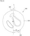
- FIG. 8 is a view describing a position relation of a fixing protrusion of the valve assembly
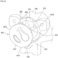
- FIGS. 9 and 10 are partial perspective views illustrating a state in which the valve assembly is coupled to a cylinder.
- the valve assembly 420 includes a valve plate 421 forming a main body.
- the valve plate 421 may be formed of a circular or oval plate as shown.
- a suction inlet 422a in communication with the suction space (S) of the muffler assembly 410 to suction a refrigerant in the suction space (S) into the compression space (C) of the cylinder 330 is disposed at the valve plate 421.
- the valve assembly 420 may include a suction valve 422 mounted on a rear surface portion 421b provided at the rear of the valve plate 421 to open or close the suction inlet 422a.
- a discharge outlet 423a in communication with the discharge space (D) of the muffler assembly 410 to discharge a refrigerant compressed in the compression space (C) to the discharge space (D) is disposed at the valve plate 421.
- the valve assembly 420 may include a discharge valve 423 mounted on a front surface portion 421a of the valve plate 421 to open or close the discharge outlet 423a.
- a discharge valve 423 mounted on a front surface portion 421a of the valve plate 421 to open or close the discharge outlet 423a.
- the discharge outlet 423a is opened as the discharge valve 423 is bent toward the discharge space (D), and a refrigerant in the compression space (C) is discharged to the discharge space (D).
- the suction valve 422 closes the suction inlet 422a. Consequently, the refrigerant compressed in the cylinder 330 may be discharged to the discharge space (D) instead of being discharged to the suction space (S).
- valve assembly 420 is assembled to the cylinder 330 with front and rear directions thereof reversed, a problem may occur since a refrigerant flow is changed.
- the valve assembly 420 may further include a plurality of fixing protrusions 425 and 426.
- the plurality of fixing protrusions 425 and 426 may be configured to ensure that front and rear assembling directions are not reversed when the valve assembly 420 is assembled to the cylinder 330.
- the plurality of fixing protrusions 425 and 426 may include a first fixing protrusion 425 disposed at one side of an edge portion 424, and a second fixing protrusion 426 disposed to be a predetermined interval apart from the first fixing protrusion 425.
- the first fixing protrusion 425 and the second fixing protrusion 426 may be formed with different widths or sizes from each other.
- a distance from a central portion of the first fixing protrusion 425 to a central portion of the second fixing protrusion 426 which extends clockwise along the edge portion 424 may be called l 1, and the distance which extends counterclockwise may be called l 2.
- the first fixing protrusion 425 and the second fixing protrusion 426 may be disposed such that l is shorter than l 2 (see FIG. 6 ).
- first fixing protrusion 425 and the second fixing protrusion 426 may be described in terms of an angle.
- a segment connecting the center (o) of the valve plate 421 to the central portion of the first fixing protrusion 425 may be "a”
- a segment connecting the center (o) of the valve plate 421 to the second fixing protrusion 426 may be "b.”
- the first fixing protrusion 425 and the second fixing protrusion 426 may be disposed such that the angle between the segments "a” and "b" is less than 180° (see FIG. 7 ).
- the central portion of the second fixing protrusion 426 and the central portion of the first fixing protrusion 425 are disposed a predetermined distance (d) from a vertical line (L) passing through the center (o) of the valve plate 421.
- predetermined distance (d) There are no limitations in the predetermined distance (d) as long as the length of the predetermined distance (d) is greater than 0 and equal to or shorter than a radius of the valve plate 421 (see FIG. 8 ).
- first fixing protrusion 425 and the second fixing protrusion 426 are disposed as described above, shapes of the exteriors of the front surface portion 421a and the rear surface portion 421b of the valve assembly 420 do not overlap.
- the valve assembly 420 may further include contact protrusions 427a, 427b, and 427c which protrude from the edge portion 424.
- the contact protrusions 427a, 427b, and 427c may be disposed at equidistant intervals of 120°. However, the number and arrangement angle of the contact protrusions 427a, 427b, and 427c are not limited thereto and may be varied is desired.
- the contact protrusions 427a, 427b, and 427c may be formed with smaller widths or sizes than the plurality of fixing protrusions 425 and 426.
- the cylinder 330 may include a planar portion or section 331 on which the valve assembly 420 is seated.
- the rear surface portion 421b of the valve plate 421 may be supported by the planar portion 331 when the valve assembly 420 is coupled to the cylinder 330.
- the cylinder 330 may further include an assembly fixing portion 334 formed by protruding from the planar portion 331.
- the assembly fixing portion 334 surrounds the edge portion 424 of the valve assembly 420.
- the contact protrusions 427a, 427b, and 427c may come in direct contact with the assembly fixing portion 334.
- the contact protrusions 427a, 427b, and 427c may respectively come in contact with contact portions 337a, 337b, and 337c of the assembly fixing portion 334 to prevent the valve assembly 420 from moving. Accordingly, the assembled state between the valve assembly 420 and the cylinder 330 may be firmly maintained.
- a plurality of protrusion grooves 335 and 336 formed at positions corresponding to each of the fixing protrusions 425 and 426 may be disposed at the assembly fixing portion 334 when the valve assembly 420 is coupled to the cylinder 330.
- the plurality of protrusion grooves 335 and 336 may include a first protrusion groove 335 coupled to the first fixing protrusion 425, and a second protrusion groove 336 coupled to the second fixing protrusion 426.
- the plurality of protrusion grooves 335 and 336 may have shapes respectively corresponding to those of the plurality of fixing protrusions 425 and 426.
- the width of the first fixing protrusion 425 may be different from that of the second fixing protrusion 426 so that the plurality of fixing protrusions 425 and 426 and the plurality of protrusion grooves 335 and 336 are respectively coupled at corresponding positions.
- the width of the first fixing protrusion 425 may be wider or narrower than the width of the second fixing protrusion 426.
- the shape and size of the first fixing protrusion 425 and the second fixing protrusion 426 are not limited as long as the first fixing protrusion 425 cannot be inserted into the second protrusion groove 336, and the second fixing protrusion 426 cannot be inserted into the first protrusion groove 335.
- the plurality of fixing protrusions 425 and 426 may be called a "plurality of coupling portions.”
- the first fixing protrusion 425 may be called a "first coupling portion”
- the second fixing protrusion 426 may be called a "second coupling portion.”
- the plurality of protrusion grooves 335 and 336 may be called a "plurality of corresponding coupling portions.”
- the first protrusion groove 335 into which the first fixing protrusion 425 is inserted may be called a "first corresponding coupling portion”
- the second protrusion groove 336 into which the second fixing protrusion 426 is inserted may be called a "second corresponding coupling portion.”
- valve plate may further include an additional fixing protrusion in addition to the plurality of fixing protrusions 425 and 426.
- the cylinder 330 may further include a protrusion groove corresponding to the additional fixing protrusion.
- a plurality of protrusion grooves may be formed at the edge portion 424 of the valve assembly 420, and a plurality of fixing protrusions formed at positions corresponding to the plurality of protrusion grooves (not shown) may be formed at the assembly fixing portion 334 of the cylinder 330.
- the plurality of fixing protrusions 425 and 426 be formed at the valve assembly 420, and the plurality of protrusion grooves 335 and 336 be formed at the cylinder 330.
- one fixing protrusion and one protrusion groove may be formed at the edge portion 424.
- a protrusion groove or a fixing protrusion corresponding to each of the one fixing protrusion and the one protrusion groove may be formed at the assembly fixing portion 334.
- the second fixing protrusion 426 of the edge portion 424 in the first embodiment may be changed into a protrusion groove. Consequently, in the present embodiment, the first fixing protrusion 425 is formed at the edge portion 424, and the first protrusion groove 335 into which the first fixing protrusion 425 is inserted is formed at the assembly fixing portion 334 as in the first embodiment.
- a protrusion groove may be formed at the edge portion 424, and a fixing protrusion corresponding to the protrusion groove may be formed at the assembly fixing portion 334.
- the plurality of fixing protrusions 425 and 426 or a plurality of protrusion grooves formed at the valve assembly 420 may be collectively called a "plurality of coupling portions," and a plurality of fixing protrusions or the plurality of protrusion grooves 335 and 336 formed at the cylinder 330 at positions respectively corresponding to the plurality of coupling portions may be collectively called a "plurality of corresponding coupling portions.”
- the valve assembly 420 may be prevented from being erroneously assembled with front and rear surfaces thereof reversed when the valve assembly 420 is coupled to the cylinder 330 by the plurality of coupling portions and the plurality of corresponding coupling portions.
- erroneously assembling of a valve assembly may be prevented when the valve assembly is assembled to a cylinder.
- the first gasket 440 may be called a gasket 440
- the second gasket 450 may be called a suction gasket 450.
- FIGS. 11 and 12 are views for describing states of the reciprocating compressor in FIG. 1 before and after a gasket is fastened to a muffler assembly
- FIG. 13 is a front view of the gasket in FIG. 11
- FIG. 14 is a rear view of the gasket in FIG. 11 .
- the gasket 440, the valve assembly 420, and the suction gasket 450 may be sequentially coupled to the muffler assembly 410.
- the valve assembly 420 guides a refrigerant discharged from the muffler assembly 410 to the cylinder 330, or guides a refrigerant compressed in the cylinder 330 to the muffler assembly 410.
- the gasket 440 prevents leakage of a refrigerant flowing between the muffler assembly 410 and the valve assembly 420.
- the suction gasket 450 prevents leakage of a refrigerant flowing between the valve assembly 420 and the cylinder 330.
- the muffler assembly 410 includes the suction/discharge part 411 with which the gasket 440 comes in contact.
- the suction/discharge part 411 may be formed in a circular or oval shape, but the shape is not limited thereto.
- a refrigerant inlet 412 for supplying a refrigerant to the cylinder 330 may be formed at the suction/discharge part 411.
- the refrigerant inlet 412 may be in communication with the suction space (S).
- a refrigerant flow between the refrigerant inlet 412 and the cylinder 330 may be guided by the valve assembly 420.
- a refrigerant outlet 413 for discharging a refrigerant compressed in the cylinder 330 may be formed at the suction/discharge part 411.
- the refrigerant outlet 413 may be in communication with the compression space (C).
- a refrigerant flow between the refrigerant outlet 413 and the cylinder 330 may be guided by the valve assembly 420.
- the refrigerant outlet 413 may be formed to be greater in size than the refrigerant inlet 412 because a pressure at which a refrigerant compressed in the cylinder 330 is discharged to the refrigerant outlet 413 is greater than a pressure at which a refrigerant is introduced into the cylinder 330 from the refrigerant inlet 412.
- the suction/discharge part 411 may further include a plurality of protruding surfaces 414 and 415 configured to extend from an outer edge of the suction/discharge part 411.
- the two protruding surfaces 414 and 415 may include a first protruding surface 414 and a second protruding surface 415 apart from the first protruding surface 414.
- the first protruding surface 414 and the second protruding surface 415 may be disposed to extend parallel to an axis of the suction/discharge part 411. Furthermore, the first protruding surface 414 and the second protruding surface 415 may have a predetermined height difference from the suction/discharge part 411.
- the muffler assembly 410 may further include a plurality of fastening protrusions 414a and 415a disposed at the plurality of protruding surfaces 414 and 415 to protrude toward the cylinder 330.
- the plurality of fastening protrusions 414a and 415a may include a first fastening protrusion 414a configured to protrude from the first protruding surface 414 toward the cylinder 330, and a second fastening protrusion 415a configured to protrude from the second protruding surface 415 toward the cylinder 330.
- a number of the plurality of fastening protrusions 414a and 415a is not limited to two, and may be varied if desired. For example, three or four fastening protrusions may be formed.
- the plurality of fastening protrusions 414a and 415a may be formed not only at the plurality of protruding surfaces 414 and 415, but also at the cylinder 330. In this case, the plurality of fastening protrusions 414a and 415a may be formed at an upper portion of the cylinder 330.
- the first fastening protrusion 414a and the second fastening protrusion 415a may be formed in cylindrical shapes of different sizes. Specifically, a diameter of a cross-sectional portion of the first fastening protrusion 414a may be formed greater than a diameter of a cross-sectional portion of the second fastening protrusion 415a. Conversely, the diameter of the cross-sectional portion of the second fastening protrusion 415a may be formed greater than the diameter of the cross-sectional portion of the first fastening protrusion 414a.
- the first fastening protrusion 414a and the second fastening protrusion 415a may be respectively fitted into a plurality of erroneous assembly prevention holes 446 and 447. Accordingly, the gasket 440 may be coupled to the muffler assembly 410 in a proper orientation.
- the gasket 440 includes a main body portion 441.
- the main body portion 441 may be formed in the shape of a thin circular or oval plate as shown in the drawings, but the shape is not limited thereto.
- the gasket 440 may further include a first flow hole 442 and a second flow hole 443 being in communication with the refrigerant inlet 412 and the refrigerant outlet 413, respectively.
- a refrigerant in the suction space (S) may flow to the cylinder 330 through the first flow hole 442, and a refrigerant compressed in the cylinder 330 may flow to the discharge space (D) through the second flow hole 443.
- the first flow hole 442 and the second flow hole 443 may be formed in shapes corresponding to the refrigerant inlet 412 and the refrigerant outlet 413, respectively.
- the gasket 440 may further include a first coupling portion 444 and a second coupling portion 445 extending from one side of the main body portion 441 in a radial direction of the main body portion 441.
- the first coupling portion 444 and the second coupling portion 445 may be formed in the shape of a thin plate which is level with the main body portion 441.
- the first coupling portion 444 and the second coupling portion 445 may be disposed apart from each other.
- the gasket 440 may further include a first erroneous assembly prevention hole 446 disposed at the first coupling portion 444 and a second erroneous assembly prevention hole 447 disposed at the second coupling portion 445.
- the first erroneous assembly prevention hole 446 and the second erroneous assembly prevention hole 447 may be formed by penetrating the first coupling portion 444 and the second coupling portion 445, respectively.
- the first erroneous assembly prevention hole 446 and the second erroneous assembly prevention hole 447 may be formed in a circular shape, and be formed in different sizes.
- the first erroneous assembly prevention hole 446 and the second erroneous assembly prevention hole 447 may have the shapes and sizes corresponding to the first fastening protrusion 414a and the second fastening protrusion 415a, respectively. Consequently, the first fastening protrusion 414a is not fitted into the second erroneous assembly prevention hole 447, and the second fastening protrusion 415a is not fitted into the first erroneous assembly prevention hole 446 and the gasket 440 may be prevented from being erroneously assembled with the front and rear directions thereof reversed when the gasket 440 is assembled to the muffler assembly 410.
- a segment (s1) connecting the center of the first erroneous assembly prevention hole 446 to the center (O) of the main body portion 441 and a segment (s2) connecting the center of the second erroneous assembly prevention hole 447 to the center (O) of the main body portion 441 may be disposed to lean from opposites to a center line (v) of the gasket 440.
- an angle ⁇ between the segment (s1) and the segment (s2) is less than 180° because, if the angle between the two segments (s1, s2) is equal to 180°, the gasket 440 may be erroneously assembled even if the size of the first erroneous assembly prevention hole 446 and the size of the second erroneous assembly prevention hole 447 are different from each other.
- a load of the gasket 440 may be supported when the first fastening protrusion 414a and the second fastening protrusion 415a are fitted into the first erroneous assembly prevention hole 446 and the second erroneous assembly prevention hole 447. Consequently, a separate gasket fixing member is not required and assembling the gasket 440 becomes easy.
- the plurality of erroneous assembly prevention holes 446 and 447 are described as being disposed at the plurality of coupling portions 444 and 445, it is understood that a plurality of erroneous assembly prevention holes 446 and 447 may be disposed at the main body portion 441.
- the plurality of fastening protrusions 414a and 415a may be disposed in shapes corresponding to positions respectively corresponding to the plurality of erroneous assembly prevention holes 446 and 447 on an upper portion of the suction/discharge part 411.
- the plurality of erroneous assembly prevention holes 446 and 447 need not be disposed at the separate coupling portions 444 and 445 as long as the structure does not allow the gasket 440 to be erroneously assembled with front and rear directions thereof reversed.
- each of the plurality of erroneous assembly prevention holes 446 and 447 may have a different shape.
- the first erroneous assembly prevention hole 446 may be formed in a circular shape
- the second erroneous assembly prevention hole 447 may be formed in a rectangular or triangular shape
- the plurality of fastening protrusions 414a and 415a are formed in shapes respectively corresponding to the plurality of erroneous assembly prevention holes 446 and 447.
- the first fastening protrusion 414a is fitted only into the first erroneous assembly prevention hole 446 without being fitted into the second erroneous assembly prevention hole 447, and the second fastening protrusion 415a is fitted into the second erroneous assembly prevention hole 447.
- the reciprocating compressor 10 prevents the gasket 440 from being erroneously assembled, thereby reliably maintaining airtightness between the cylinder 330 and the muffler assembly 410. Accordingly, the reciprocating compressor 10 according to the present embodiment is capable of preventing leakage of a flowing refrigerant and promoting a smooth refrigerant flow.
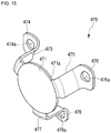
- FIG. 15 is a perspective view of the clamp in FIG. 2
- FIG. 16 is a front view of the clamp in FIG. 15 .
- the clamp 470 includes a main body portion 471 disposed in front of the suction/discharge unit 400 (see FIG. 2 ).
- the main body portion 471 may be formed in the shape of a thin circular or oval plate. However, the shape of the main body portion 471 is not limited thereto.
- the clamp 470 may further include a plurality of legs 473, 475, and 477 extending from the main body portion 471 toward the cylinder 330 (see FIG. 2 ).
- Each of the legs 473, 475, and 477 may extend from an edge portion 471a forming an outer circumferential surface of the main body portion 471.
- the legs 473, 475, and 477 are disposed apart from each other in a circumferential direction of the edge portion 471a.
- Each of the legs 473, 475, and 477 may be disposed to correspond to an angle formed between the plurality of fastening holes 314, 316, and 318 (see FIG. 4 ).
- the plurality of fastening holes 314, 316, and 318 may be disposed to form different angles from each other.
- the plurality of legs 473, 475, and 477 may be formed to have the same shape.
- the shape of the legs are not limited thereto and may be varied if desired.
- the clamp 470 may further include the mount portions 474, 476, and 478 extending from the legs 473, 475, and 477, respectively.
- the plurality of mount portions 474, 476, and 478 may be formed of a plate extending parallel to the main body portion 471 in a radial direction of the main body portion 471.
- Each of the mount portions 474, 476, and 478 may be formed in a different shape or size. Accordingly, the clamp 470 may be prevented from being erroneously assembled.
- the through holes 474a, 476a, and 478a may be disposed at the mount portions 474, 476, and 478, respectively.
- the fastening members 484, 486, and 488, (see FIG. 4 ) may penetrate through the through holes 474a, 476a, and 478a, respectively. Accordingly, the clamp 470 is mounted on the cylinder block 310 (see FIG. 4 ).
- the plurality of legs 473, 475, and 477 and the plurality of mount portions 474, 476, and 478 may be collectively called a "plurality of bridge parts.”
- a bridge part may collectively represent one leg and one mount portion extending from the one leg.
- the leg 473 and the mount portion 474 extending from the leg 473 may be collectively called a first bridge part.
- FIGS. 17 and 18 are views illustrating a state in which the suction/discharge unit in FIG. 4 is coupled to the muffler assembly.
- the clamp 470 when the clamp 470 is fastened to the cylinder block 310, the clamp 470 may surround and support the suction/discharge part 411.
- the main body portion 471 may be disposed to come in contact with the front surface portion 419 (see FIG. 4 ) formed in front of the suction/discharge part 411, and the plurality of legs 473, 475, and 477 may be disposed to surround the outer circumferential surface of the suction/discharge part 411.
- the first leg 473 is disposed between the first protrusion 414b and the suction muffler 416.
- the second leg 475 is disposed between the second protrusion 415b and the discharge muffler 418.
- the third leg 477 is disposed between the suction muffler 416 and the discharge muffler 418.
- the reciprocating compressor 10 can fix the suction/discharge unit 400 formed of a plurality of members to the cylinder block 310 using the clamp 470.
Landscapes
- Engineering & Computer Science (AREA)
- Mechanical Engineering (AREA)
- General Engineering & Computer Science (AREA)
- Compressor (AREA)
Abstract
Description
- The present invention relates, generally, to a reciprocating compressor and, more particularly, to a suction/discharge assembly of a reciprocating compressor.
- A reciprocating compressor is an apparatus that compresses a fluid by suctioning, compressing, and discharging a refrigerant by a reciprocating motion of a piston inside a cylinder. The reciprocating compressor may be classified as a connected type reciprocating compressor or a vibrating type reciprocating compressor in accordance with a method of driving a piston. Here, the connected type reciprocating compressor compresses a refrigerant by a reciprocating motion inside a cylinder of a piston connected to a rotary shaft of a driving unit through a connecting rod, and the vibrating type reciprocating compressor compresses a refrigerant by a reciprocating motion inside a cylinder of a piston which vibrates by being connected to a mover of a reciprocating motor.
- The connected type reciprocating compressor is disclosed in Korean Unexamined Patent Application Publication No.
10-2010-0085760 - A suction/discharge part introducing a refrigerant into the cylinder or having a refrigerant compressed in the cylinder introduced thereinto is disposed at the suction/discharge unit. In addition, a valve assembly for guiding suction or discharge of a refrigerant is included between the suction/discharge part and the cylinder.
- The valve assembly includes a suction valve and a discharge valve. In a process in which a refrigerant is suctioned and discharged, the suction valve may operate to be open toward the rear with respect to a flowing direction of a refrigerant, and the discharge valve may operate to be open toward the front with respect to the flowing direction of the refrigerant. Consequently, malfunctioning of a valve due to an erroneous direction of assembling the valve assembly may be a problem.
- However, a device that guides a direction of assembling a valve assembly is not included in a conventional compressor, and therefore the valve assembly cannot perform its original function when the valve assembly is assembled with front and rear directions thereof reversed.
- Meanwhile, a gasket for preventing leakage of a refrigerant is disposed between the valve assembly and the suction/discharge part. The gasket maintains airtightness between the valve assembly and a muffler assembly.
- Generally, since a refrigerant inlet and a refrigerant outlet formed at the suction/discharge part have different sizes or shapes from each other, the gasket also has flow holes of different shapes to correspond to the size or shape of the refrigerant inlet and the refrigerant outlet. Consequently, when the gasket is erroneously assembled, problems such as leakage of a refrigerant may occur since the airtightness between the muffler assembly and the cylinder is not maintained.
- In addition, the suction/discharge part has to come in close contact with the cylinder and be mounted. However, when a plurality of fastening members are used to couple the suction/discharge part to the cylinder, a structure of a compressor becomes complex and assembling the compressor becomes difficult.
- An aspect of the present invention is to provide a reciprocating compressor which has a structure capable of preventing a valve assembly and a gasket from being erroneously assembled, and using a clamp to integrally couple a suction/discharge unit to a compression unit.
- According to an aspect of the present invention, a reciprocating compressor may include a driving unit; a connecting rod; a piston; a cylinder; and a valve assembly, wherein the valve assembly may include a valve plate forming a main body, a suction inlet and a discharge outlet disposed at the valve plate and coming in communication with a compression space of the cylinder to guide a refrigerant flow, a suction valve and a discharge valve disposed at the valve plate and selectively opening the suction inlet and the discharge outlet, and a plurality of coupling portions disposed at the valve plate, and a plurality of corresponding coupling portions disposed to correspond to each of the plurality of coupling portions and preventing the valve assembly from being erroneously assembled may be disposed at the cylinder.
- Specifically, a reciprocating compressor may comprise:
a driver configured to provide a rotary force; a connecting rod coupled to the driver to convert a rotary motion to a linear motion; a compression unit having a piston connected to the connecting rod to linearly reciprocate, and a cylinder configured to accommodate the piston and having a compression space for compressing a refrigerant by the linear reciprocating motion of the piston; a suction/discharge part having a refrigerant inlet for supplying a refrigerant to the cylinder and a refrigerant outlet for discharging a refrigerant compressed in the cylinder; and a valve assembly installed at a portion of the cylinder between the suction/discharge part and the cylinder to selectively allow a refrigerant to flow, the valve assembly including: a valve plate; a suction inlet and a discharge outlet disposed at the valve plate, and configured to be in communication with the compression space of the cylinder to guide a refrigerant flow; a suction valve disposed at the valve plate to selectively open the suction inlet; a discharge valve disposed at the valve plate to selectively open the discharge outlet; and at least one valve plate coupling portion at the valve plate, and at least one cylinder coupling portion at the cylinder and coupled to the at least one valve plate coupling portion, wherein the combination of the at least one valve plate coupling portion and the at least one cylinder coupling portion are configured such that the valve plate is mountable to the cylinder when facing a first direction and is not mountable to the cylinder when facing a second direction opposite the first direction. - The at least one valve plate coupling portion may include a plurality of valve plate coupling portions, and the at least one cylinder coupling portion may include a plurality of cylinder coupling portions.
- The valve plate may include an edge portion configured to form an outer circumferential surface of the valve plate; and the plurality of valve plate coupling portions may be formed at the edge portion.
- The plurality of valve plate coupling portions may include a first valve plate coupling portion and a second valve plate coupling portion disposed at the edge portion, the first valve plate coupling portion being spaced from the second valve plate coupling portion.
- At least the second valve plate coupling portion may be disposed such that a central portion of the second valve plate coupling portion is spaced apart from a vertical line which passes through the center of the valve plate.
- A contact protrusion configured to come in contact with one side of the cylinder to prevent the valve assembly from moving may be formed at the edge portion of the valve assembly.
- Each valve plate coupling portion of the plurality of valve plate coupling portions may be formed with a different width or size relative to the other valve plate coupling portions of the plurality of valve plate coupling portions.
- The plurality of valve plate coupling portions may include two or more fixing protrusions configured to protrude from the valve plate.
- The plurality of cylinder coupling portions may include two or more protrusion grooves into which the two or more fixing protrusions are inserted.
- The reciprocating compressor may further comprise: a gasket mounted between the suction/discharge part and the valve assembly, and configured to be in communication with each of the refrigerant inlet and the refrigerant outlet; and a plurality of fastening protrusions formed at the cylinder or the suction/discharge part, the plurality of fastening protrusions being inserted into the gasket, wherein the gasket includes a plurality of erroneous assembly prevention holes into which a corresponding fastening protrusion of the plurality of fastening protrusions is inserted, each erroneous assembly prevention hole of the plurality of erroneous assembly prevention holes having a different shape or size relative to the other erroneous assembly prevention holes of the plurality of erroneous assembly prevention holes.
- The gasket may include a first flow hole configured to be in communication with the refrigerant inlet, and a second flow hole configured to be in communication with the refrigerant outlet, and wherein the first flow hole has a different size or shape relative to the second flow hole.
- The corresponding fastening protrusion may be formed to have a same shape or size of the erroneous assembly prevention hole into which the corresponding fastening protrusion is inserted.
- The reciprocating compressor may further comprise a clamp fixing the suction/discharge part to the compression unit.
- The clamp may extend around the suction/discharge part.
- The suction/discharge unit may include an elastic member disposed to face the clamp, one side of the elastic member being supported by the suction/discharge part and the other side of the elastic member being supported by the clamp, such that the suction/discharge part and the cylinder are in close contact with each other by an elastic force of the elastic member.
- The details of one or more embodiments are set forth in the accompanying drawings and the description below. Other features will be apparent from the description and drawings, and from the claims.
-
-
FIG. 1 is a perspective view of a reciprocating compressor according to an embodiment of the present invention; -
FIG. 2 is an exploded perspective view of the reciprocating compressor inFIG. 1 ; -
FIG. 3 is a cross-sectional view of the reciprocating compressor inFIG. 1 ; -
FIGS. 4 and 5 are exploded perspective views of a suction/discharge unit and a muffler assembly; -
FIGS. 6 and7 are views illustrating a front surface portion and a rear surface portion of a valve assembly, respectively; -
FIG. 8 is a view describing a position relation of a fixing protrusion of the valve assembly; -
FIGS. 9 and10 are partial perspective views illustrating a state in which the valve assembly is coupled to a cylinder; -
FIGS. 11 and 12 are views for describing states of the reciprocating compressor inFIG. 1 before and after a gasket is fastened to the muffler assembly; -
FIG. 13 is a front view of the gasket inFIG. 11 ; -
FIG. 14 is a rear view of the gasket inFIG. 11 ; -
FIG. 15 is a perspective view of a clamp inFIG. 2 ; -
FIG. 16 is a front view of the clamp inFIG. 1 ; and -
FIGS. 17 and18 are views illustrating a state in which the suction/discharge unit inFIG. 4 is coupled to the muffler assembly. - Reference will now be made in detail to the embodiments of the present disclosure, examples of which are illustrated in the accompanying drawings.
- In the following detailed description of the preferred embodiments, reference is made to the accompanying drawings that form a part hereof, and in which are shown by way of illustration specific preferred embodiments in which the invention may be practiced. These embodiments are described in sufficient detail to enable those skilled in the art to practice the invention, and it is understood that other embodiments may be utilized and that logical structural, mechanical, electrical, and chemical changes may be made without departing from the spirit or scope of the invention. To avoid detail not necessary to enable those skilled in the art to practice the invention, the description may omit certain information known to those skilled in the art. The following detailed description is, therefore, not to be taken in a limiting sense.
- Also, in the description of embodiments, terms such as first, second, A, B, (a), (b) or the like may be used herein when describing components of the present invention. These terms are not used to define an essence, order or sequence of a corresponding component but used merely to distinguish the corresponding component from other component (s). It should be noted that if it is described in the specification that one component is "connected," "coupled" or "joined" to another component, the former may be directly "connected," "coupled" or "joined" to the latter or "connected," "coupled" or "joined" to the latter via another component.
-
FIG. 1 is a perspective view of a reciprocating compressor according to an embodiment of the present invention. - Referring to
FIG. 1 , a reciprocatingcompressor 10 according to an embodiment of the present invention may include ahousing shell 100 forming an exterior. - The
housing shell 100 forms a closed space therein, and accommodates various types of parts forming thereciprocating compressor 10 in the closed space. Thehousing shell 100 may be formed of a metallic material. - The
housing shell 100 may include abase shell 110 and acover shell 160. Thebase shell 110 and thecover shell 160 are formed in a nearly hemispherical shape and form an accommodation space therein. Thecover shell 160 packages thebase shell 110 at an upper portion of thebase shell 110 to form a closed accommodation space therein. - A
suction pipe 120, adischarge pipe 130, and aprocess pipe 140 may be disposed at thebase shell 110. - The
suction pipe 120 may introduce a refrigerant into an inner portion of thehousing shell 100, and be mounted by penetrating thebase shell 110. Thesuction pipe 120 may be mounted separately from thebase shell 110 or be integrally formed with thebase shell 110. - The
discharge pipe 130 discharges a refrigerant compressed in thehousing shell 100, and is mounted by penetrating thebase shell 110. Thedischarge pipe 130 may also be mounted separately from thebase shell 110 or integrally formed with thebase shell 110. - The
process pipe 140 is for charging a refrigerant into an inner portion of thehousing shell 100 after sealing the inner portion of thehousing shell 100, and may be mounted by penetrating thebase shell 110 as thesuction pipe 120 and thedischarge pipe 130. - The reciprocating
compressor 10 may further include a power unit (not shown) disposed at thebase shell 110. The power unit (not shown) is for supplying power to various types of parts accommodated inside thehousing shell 100, and may be mounted by penetrating thebase shell 110. -
FIG. 2 is an exploded perspective view of the compressor inFIG. 1 , andFIG. 3 is a cross-sectional view of the compressor inFIG. 1 . - Referring to
FIGS. 2 and3 , the reciprocatingcompressor 10 may further include a driving unit ordriver 200 disposed in thehousing shell 100 and providing a driving force. - The driving
unit 200 may include astator core 210 which corresponds to a portion fixed during an operation of thedriving unit 200, and astator coil 220 mounted inside thestator core 210. Thestator core 210 and thestator coil 220 are collectively called a "stator." - The
stator core 210 may be formed of a metallic material, and formed in a nearly cylindrical shape. - When voltage is applied from the power unit (not shown), the
stator coil 220 may generate an electromagnetic force to perform an electromagnetic interaction with thestator core 210 and arotor 240 to be described later. - The driving
unit 200 may further include aninsulator 230 disposed between thestator core 210 and thestator coil 220. - The
insulator 230 prevents direct contact between thestator core 210 and thestator coil 220, because if thestator coil 220 comes in direct contact with thestator core 210, generation of an electromagnetic force from thestator coil 220 may be interrupted. To prevent this, theinsulator 230 separates thestator core 210 from thestator coil 220 at a predetermined distance. - The driving
unit 200 may further include therotor 240 corresponding to a portion which rotates during the operation of thedriving unit 200. - A magnet may be disposed at the
rotor 240. Accordingly, when voltage is applied, therotor 240 rotates by the electromagnetic interaction with thestator core 210 and thestator coil 220. - A rotary force in accordance with the rotation of the
rotor 240 acts as a driving force capable of driving a compression unit orcompressor 300 to be described later. In other words, in the present embodiment, a driving force of thecompression unit 300 may be generated by the rotary force of therotor 240. - The driving
unit 200 may further include arotary shaft 250 which penetrates therotor 240 and is mounted inside therotor 240 along a vertical direction. Therotary shaft 250 may rotate together with therotor 240 when therotor 240 rotates. - The
rotary shaft 250 may include abase shaft 252, arotary plate 254, and aneccentric shaft 256. - The
base shaft 252 is mounted in therotor 240 in a vertical direction (z-axis direction). Thebase shaft 252 rotates together with therotor 240 in accordance with the rotation of therotor 240. - The
rotary plate 254 is mounted on one end portion of thebase shaft 252, and is rotatably mounted on a rotaryplate seating unit 320 of acylinder block 310. - The
eccentric shaft 256 is formed by protruding from a top surface of therotary plate 254. Theeccentric shaft 256 protrudes from a position which is eccentric from an axial center of thebase shaft 252 to eccentrically rotate when therotary plate 254 rotates. A connectingrod 340 is mounted on theeccentric shaft 256. - The reciprocating
compressor 10 may further include thecompression unit 300 disposed inside thehousing shell 100 and receiving a driving force from the drivingunit 200 to compress a refrigerant by a straight or linear reciprocating motion. - The
compression unit 300 includes thecylinder block 310 disposed above therotor 240. - The
cylinder block 310 may include the rotaryplate seating unit 320 formed at a lower portion of thecylinder block 310, and acylinder 330 formed at a front surface portion of thecylinder block 310. - The rotary
plate seating unit 320 may rotatably accommodate therotary plate 254. Furthermore, ashaft opening 322 through which thebase shaft 252 may penetrate is formed at the rotaryplate seating unit 320. - An opening may be formed at the
cylinder 330, and apiston 350 to be described later may be inserted into thecylinder 330 through the opening. - The
cylinder 330 may be formed of an aluminum material. The aluminum material may be aluminum or an aluminum alloy. Due to the aluminum material, which is a substantially nonmagnetic substance, a magnetic flux generated in therotor 240 is not transmitted to thecylinder 330. Accordingly, in the present embodiment, the magnetic flux generated in therotor 240 may be prevented from being transmitted to thecylinder 330 and leaking outside thecylinder 330. - The
compression unit 300 may further include thepiston 350 for compressing a refrigerant. - The
piston 350 is accommodated inside thecylinder 330 to linearly reciprocate in front and rear directions (x-axis direction). In accordance with the reciprocating motion of thepiston 350, a compression space (C) in which a refrigerant introduced from thesuction pipe 120 is compressed is formed inside thecylinder 330. - The compression space (C) is a space formed at an inner portion of the
cylinder 300, and refers to a space in which a refrigerant flows at a gap portion between thepiston 350 and avalve assembly 420. - The
piston 350 may be formed of an aluminum material like thecylinder 330. Accordingly, in the present embodiment, a magnetic flux generated in therotor 240 may be prevented from being transmitted to thepiston 350 and leaking outside thepiston 350 as in thecylinder 330 - Furthermore, as the
piston 350 is formed of the same material as thecylinder 330, thepiston 350 has a thermal expansion coefficient almost equal to that of thecylinder 330. As the thermal expansion coefficient of thepiston 350 is almost equal to that of thecylinder 330, thepiston 350 is thermally deformed almost as much as thecylinder 330 in an internal environment of thehousing shell 100 at a high temperature (generally, approximately 100 °C) when the reciprocatingcompressor 10 operates. Accordingly, interference between thepiston 350 and thecylinder 330 may be prevented when thepiston 350 reciprocates in thecylinder 330. - The
compression unit 300 may further include the connectingrod 340 for transmitting a driving force provided from the drivingunit 200 to thepiston 350. The connectingrod 340 may be formed of a sintered alloy material. - One side of the connecting
rod 340 is connected to therotary shaft 250 to convert a rotary motion transmitted from therotor 240 into a linear reciprocating motion. Specifically, the connectingrod 340 linearly reciprocates in front and rear directions (x-axis direction) in accordance with eccentric rotation of theeccentric shaft 256. - The other side of the connecting
rod 340 is connected to thepiston 350. Thepiston 350 linearly reciprocates in thecylinder 330 in accordance with the linear reciprocating motion of the connectingrod 340. - The
compression unit 300 may further include apiston pin 370 for coupling thepiston 350 to the connectingrod 340. - Specifically, the
piston pin 370 may penetrate thepiston 350 and the connectingrod 340 in the vertical direction (z-axis direction) to connect thepiston 350 to the connectingrod 340. - The reciprocating
compressor 10 may further include a suction/discharge unit or suction/discharge assembly 400 that is disposed inside thehousing shell 100, and suctions a refrigerant in order to compress the refrigerant in thecompression unit 300 and discharges the compressed refrigerant from thecompression unit 300. - The suction/
discharge unit 400 may be disposed in front of thecompression unit 300 as shown. - In this exemplary embodiment, a term "front" or "front surface portion" signifies a direction from the
compression unit 300 toward the suction/discharge unit 400, and a term "rear" or "rear surface portion" signifies the opposite direction. In addition, the term "front" may signify a positive direction of the x-axis, and the term "rear" may signify a negative direction of the x-axis. Unless noted otherwise, the definitions of the directions are identically applied throughout the present specification. - The suction/
discharge unit 400 may include amuffler assembly 410. - The
muffler assembly 410 transfers a refrigerant suctioned from thesuction pipe 120 to an inner portion of thecylinder 330, and transfers a refrigerant compressed in the compression space (C) of thecylinder 330 to thedischarge pipe 130. For this, a suction space (S) which accommodates the refrigerant suctioned from thesuction pipe 120 and a discharge space (D) which accommodates the refrigerant compressed in the compression space (C) of thecylinder 330 are provided at themuffler assembly 410. - The suction/
discharge unit 400 may further include thevalve assembly 420 disposed between thecylinder 330 and themuffler assembly 410. - The
valve assembly 420 may be assembled to a front surface portion of thecylinder 330, and guide a refrigerant in the suction space (S) to the inner portion of thecylinder 330 or guide a refrigerant compressed in thecylinder 330 to the discharge space (D). - The
valve assembly 420 will be described in detail with reference toFIGS. 6 and7 . - The suction/
discharge unit 400 may further include adischarge hose 430 disposed at one side of themuffler assembly 410. - The
discharge hose 430 may function as a middle passage which transfers a compressed refrigerant accommodated in the discharge space (D) to thedischarge pipe 130. One end portion of thedischarge hose 430 is mounted on themuffler assembly 410 to come in communication with the discharge space (D), and the other end portion of thedischarge hose 430 is mounted to come in communication with thedischarge pipe 130. - The suction/
discharge unit 400 may include afirst gasket 440 mounted between themuffler assembly 410 and thevalve assembly 420, and asecond gasket 450 mounted between thevalve assembly 420 and thecylinder 330. Thegaskets - The
first gasket 440 and thesecond gasket 450 may be formed nearly in the shape of a ring, but the shape is not limited thereto and may be varied as desired so long as the shape is a structure capable of preventing leakage of a refrigerant. Thefirst gasket 440 will be described in detail with reference toFIGS. 11 to 14 . - The suction/
discharge unit 400 may further include anelastic member 460 mounted in front of themuffler assembly 410. - The
elastic member 460 is a device for supporting themuffler assembly 410 during an operation of thereciprocating compressor 10, and theelastic member 460 may be a Belleville spring. - The suction/
discharge unit 400 may further include aclamp 470 mounted on a front surface portion of themuffler assembly 410. - The
clamp 470 fixes thevalve assembly 420, thefirst gasket 440, thesecond gasket 450, theelastic member 460, and themuffler assembly 410 to thecylinder block 310. Theclamp 470 may be formed nearly in the shape of a trivet, and mounted on thecylinder 330 by a fastener such as a screw. - The reciprocating
compressor 10 may include afront damper 500, arear damper 550, andlower dampers reciprocating compressor 10. - The
front damper 500 buffers vibration of the suction/discharge unit 400 and is mounted on a front upper portion of themuffler assembly 410. Thefront damper 500 may be formed of a rubber material. - The
rear damper 550 buffers vibration of thecompression unit 300, and is mounted on a rear upper portion of thecylinder block 310. Therear damper 550 may also be formed of a rubber material like thefront damper 500. - The
lower dampers driving unit 200 and are provided in a plurality. Thelower dampers lower damper 600 and a rearlower damper 650. - The front
lower damper 600 buffers front vibration of thedriving unit 200 and is mounted on a front lower portion of thestator core 210. The rearlower damper 650 buffers a rear vibration of thedriving unit 200 and is mounted on a rear lower portion of thestator core 210. - The reciprocating
compressor 10 may further include abalance weight 700 which is coupled to theeccentric shaft 256 at an upper portion of the connectingrod 340. Thebalance weight 700 may control rotary vibration when therotary shaft 250 rotates. -
FIGS. 4 and 5 are exploded perspective views of a suction/discharge unit and a muffler assembly. - Referring to
FIGS. 4 and 5 , themuffler assembly 410, thefirst gasket 440, thevalve assembly 420, and thesecond gasket 450 are disposed in order between theclamp 470 and thecylinder block 310. - The
muffler assembly 410 may further include a suction/discharge part 411 supplying a refrigerant to thecylinder 330 or having a refrigerant compressed in thecylinder 330 introduced thereinto. The suction/discharge part 411 may be formed in a cylindrical shape. - A
rear surface portion 411a of the suction/discharge part 411 is disposed to face the opening of thecylinder 330. In addition, therear surface portion 411a comes in contact with thefirst gasket 440. Therear surface portion 411a may be formed in a circular shape. - A
refrigerant inlet 412 which is a passage through which a refrigerant is supplied to thecylinder 330, and arefrigerant outlet 413 which is a passage into which a refrigerant compressed in thecylinder 330 is introduced are formed at therear surface portion 411a of the suction/discharge part 411. - The
muffler assembly 410 may further include asuction muffler 416 connected to one side of the suction/discharge part 411 to suction a refrigerant into an inner portion of thehousing shell 100. The suction space (S, refer toFIG. 3 ) is formed at an inner portion of thesuction muffler 416. A refrigerant accommodated in the suction space (S) may be supplied to thecylinder 330 through therefrigerant outlet 413. - The
muffler assembly 410 may further include adischarge muffler 418 connected to another side of the suction/discharge part 411 to discharge a refrigerant compressed in thecylinder 330 to the outside of thehousing shell 100. The discharge space (D, refer toFIG. 3 ) is formed at an inner portion of thedischarge muffler 418. A refrigerant compressed in thecylinder 330 may be discharged to the discharge space (D) through therefrigerant inlet 412. - The
suction muffler 416 and thedischarge muffler 418 may be disposed apart from each other. In addition, thesuction muffler 416 and thedischarge muffler 418 may be mounted apart from each other on an outer circumferential surface of the suction/discharge part 411. - A plurality of
protrusions first gasket 440 may be disposed at the outer circumferential surface of the suction/discharge part 411. The plurality ofprotrusions first protrusion 414b and asecond protrusion 415b. Meanwhile, a number of the plurality of protrusions may be varied if desired. - The
clamp 470 may be mounted on thecylinder block 310 by a plurality offastening members fastening holes fastening members cylinder block 310. - The
clamp 470 includesmount portions cylinder block 310. Specifically, each of themount portions holes fastening holes fastening members holes fastening holes - Each of the
mount portions clamp 470 from being erroneously assembled. Specifically, each of themount portions cylinder block 310 to which they are connected. Accordingly, the throughholes fastening holes - The
elastic member 460 for supporting themuffler assembly 410 may be mounted on afront surface portion 419 of the suction/discharge part 411. In addition, theelastic member 460 may be disposed to face amain body portion 471 of theclamp 470. - When the
clamp 470 is mounted on thecylinder block 310, one side of theelastic member 460 may be supported by thefront surface portion 419, and the other side of theelastic member 460 may be supported by themain body portion 471. Accordingly, the suction/discharge part 411 and thecylinder 330 are brought into close contact with each other by an elastic force of theelastic member 460. - Hereinafter, the
valve assembly 420, thecylinder 330, and a coupling relation between the two will be described in detail. -
FIG. 6 is a view illustrating a front surface portion of a valve assembly,FIG. 7 is a view illustrating a rear surface portion of the valve assembly,FIG. 8 is a view describing a position relation of a fixing protrusion of the valve assembly, andFIGS. 9 and10 are partial perspective views illustrating a state in which the valve assembly is coupled to a cylinder. - Referring to
FIGS. 6 to 10 , thevalve assembly 420 includes avalve plate 421 forming a main body. Thevalve plate 421 may be formed of a circular or oval plate as shown. - A
suction inlet 422a in communication with the suction space (S) of themuffler assembly 410 to suction a refrigerant in the suction space (S) into the compression space (C) of thecylinder 330 is disposed at thevalve plate 421. - The
valve assembly 420 may include asuction valve 422 mounted on arear surface portion 421b provided at the rear of thevalve plate 421 to open or close thesuction inlet 422a. - A
discharge outlet 423a in communication with the discharge space (D) of themuffler assembly 410 to discharge a refrigerant compressed in the compression space (C) to the discharge space (D) is disposed at thevalve plate 421. - The
valve assembly 420 may include adischarge valve 423 mounted on afront surface portion 421a of thevalve plate 421 to open or close thedischarge outlet 423a. Hereinafter, opening and closing processes of thedischarge valve 423 and thesuction valve 422 will be examined. - When a refrigerant is suctioned into the
cylinder 330 from the suction space (S), an inner pressure of thecylinder 330 is lowered in accordance with a backward motion of thepiston 350. Accordingly, thesuction inlet 422a is opened as thesuction valve 422 is bent toward thepiston 350, and a refrigerant in the suction space (S) is introduced into the compression space (C). Here, thedischarge valve 423 closes thedischarge outlet 423a. Consequently, when thepiston 350 moves backward, a refrigerant in the suction space (S) is introduced into the compression space (C), but a refrigerant introduced into the compression space (C) is not discharged to the discharge space (D). - Conversely, when a refrigerant compressed in the compression space (C) in the
cylinder 330 is discharged, thedischarge outlet 423a is opened as thedischarge valve 423 is bent toward the discharge space (D), and a refrigerant in the compression space (C) is discharged to the discharge space (D). Here, thesuction valve 422 closes thesuction inlet 422a. Consequently, the refrigerant compressed in thecylinder 330 may be discharged to the discharge space (D) instead of being discharged to the suction space (S). - To enable the
reciprocating compressor 10 to function, it is important that a refrigerant flow through the suction space (S), the compression space (C), and the discharge space (D) in that order. If thevalve assembly 420 is assembled to thecylinder 330 with front and rear directions thereof reversed, a problem may occur since a refrigerant flow is changed. - To prevent an erroneous assembly as described above, the
valve assembly 420 may further include a plurality of fixingprotrusions protrusions valve assembly 420 is assembled to thecylinder 330. - The plurality of fixing
protrusions first fixing protrusion 425 disposed at one side of anedge portion 424, and asecond fixing protrusion 426 disposed to be a predetermined interval apart from thefirst fixing protrusion 425. Thefirst fixing protrusion 425 and thesecond fixing protrusion 426 may be formed with different widths or sizes from each other. - Specifically, an arrangement relation between the
first fixing protrusion 425 and thesecond fixing protrusion 426 will be described. - A distance from a central portion of the
first fixing protrusion 425 to a central portion of thesecond fixing protrusion 426 which extends clockwise along theedge portion 424 may be called l1, and the distance which extends counterclockwise may be called l2. Here, thefirst fixing protrusion 425 and thesecond fixing protrusion 426 may be disposed such that l is shorter than l2 (seeFIG. 6 ). - In addition, the arrangement relation between the
first fixing protrusion 425 and thesecond fixing protrusion 426 may be described in terms of an angle. - A segment connecting the center (o) of the
valve plate 421 to the central portion of thefirst fixing protrusion 425 may be "a," and a segment connecting the center (o) of thevalve plate 421 to thesecond fixing protrusion 426 may be "b." Here, thefirst fixing protrusion 425 and thesecond fixing protrusion 426 may be disposed such that the angle between the segments "a" and "b" is less than 180° (seeFIG. 7 ). - In addition, the central portion of the
second fixing protrusion 426 and the central portion of thefirst fixing protrusion 425 are disposed a predetermined distance (d) from a vertical line (L) passing through the center (o) of thevalve plate 421. There are no limitations in the predetermined distance (d) as long as the length of the predetermined distance (d) is greater than 0 and equal to or shorter than a radius of the valve plate 421 (seeFIG. 8 ). - As the
first fixing protrusion 425 and thesecond fixing protrusion 426 are disposed as described above, shapes of the exteriors of thefront surface portion 421a and therear surface portion 421b of thevalve assembly 420 do not overlap. - The
valve assembly 420 may further includecontact protrusions edge portion 424. - The
contact protrusions contact protrusions - The
contact protrusions protrusions - Hereinafter, a coupling structure between the
valve assembly 420 and thecylinder 330 will be described in detail. - The
cylinder 330 may include a planar portion orsection 331 on which thevalve assembly 420 is seated. - Since the diameter of the
valve plate 421 is smaller than the diameter of anopening 332 of thecylinder 330, therear surface portion 421b of thevalve plate 421 may be supported by theplanar portion 331 when thevalve assembly 420 is coupled to thecylinder 330. - The
cylinder 330 may further include an assembly fixing portion 334 formed by protruding from theplanar portion 331. - The assembly fixing portion 334 surrounds the
edge portion 424 of thevalve assembly 420. In addition, thecontact protrusions - The
contact protrusions contact portions valve assembly 420 from moving. Accordingly, the assembled state between thevalve assembly 420 and thecylinder 330 may be firmly maintained. - A plurality of
protrusion grooves protrusions valve assembly 420 is coupled to thecylinder 330. - The plurality of
protrusion grooves first protrusion groove 335 coupled to thefirst fixing protrusion 425, and asecond protrusion groove 336 coupled to thesecond fixing protrusion 426. The plurality ofprotrusion grooves protrusions - The width of the
first fixing protrusion 425 may be different from that of thesecond fixing protrusion 426 so that the plurality of fixingprotrusions protrusion grooves first fixing protrusion 425 may be wider or narrower than the width of thesecond fixing protrusion 426. However, the shape and size of thefirst fixing protrusion 425 and thesecond fixing protrusion 426 are not limited as long as thefirst fixing protrusion 425 cannot be inserted into thesecond protrusion groove 336, and thesecond fixing protrusion 426 cannot be inserted into thefirst protrusion groove 335. - The plurality of fixing
protrusions first fixing protrusion 425 may be called a "first coupling portion," and thesecond fixing protrusion 426 may be called a "second coupling portion." In addition, the plurality ofprotrusion grooves first protrusion groove 335 into which thefirst fixing protrusion 425 is inserted may be called a "first corresponding coupling portion," and thesecond protrusion groove 336 into which thesecond fixing protrusion 426 is inserted may be called a "second corresponding coupling portion." - Meanwhile, the valve plate may further include an additional fixing protrusion in addition to the plurality of fixing
protrusions cylinder 330 may further include a protrusion groove corresponding to the additional fixing protrusion. - While in this first embodiment, it was described that the plurality of fixing
protrusions valve assembly 420, and the plurality ofprotrusion grooves cylinder 330, the arrangement of the fixing protrusions and grooves could be varied. - For example, a plurality of protrusion grooves (not shown) may be formed at the
edge portion 424 of thevalve assembly 420, and a plurality of fixing protrusions formed at positions corresponding to the plurality of protrusion grooves (not shown) may be formed at the assembly fixing portion 334 of thecylinder 330. However, it may be preferable that the plurality of fixingprotrusions valve assembly 420, and the plurality ofprotrusion grooves cylinder 330. - As another alternative, one fixing protrusion and one protrusion groove may be formed at the
edge portion 424. Here, a protrusion groove or a fixing protrusion corresponding to each of the one fixing protrusion and the one protrusion groove may be formed at the assembly fixing portion 334. - For example, the
second fixing protrusion 426 of theedge portion 424 in the first embodiment may be changed into a protrusion groove. Consequently, in the present embodiment, thefirst fixing protrusion 425 is formed at theedge portion 424, and thefirst protrusion groove 335 into which thefirst fixing protrusion 425 is inserted is formed at the assembly fixing portion 334 as in the first embodiment. However, a protrusion groove may be formed at theedge portion 424, and a fixing protrusion corresponding to the protrusion groove may be formed at the assembly fixing portion 334. - The plurality of fixing
protrusions valve assembly 420 may be collectively called a "plurality of coupling portions," and a plurality of fixing protrusions or the plurality ofprotrusion grooves cylinder 330 at positions respectively corresponding to the plurality of coupling portions may be collectively called a "plurality of corresponding coupling portions." - The
valve assembly 420 may be prevented from being erroneously assembled with front and rear surfaces thereof reversed when thevalve assembly 420 is coupled to thecylinder 330 by the plurality of coupling portions and the plurality of corresponding coupling portions. - According to the present invention, erroneously assembling of a valve assembly may be prevented when the valve assembly is assembled to a cylinder.
- Hereinafter, a structure for preventing the
first gasket 440 from being erroneously assembled will be described in detail. For convenience of the description, thefirst gasket 440 may be called agasket 440, and thesecond gasket 450 may be called asuction gasket 450. -
FIGS. 11 and 12 are views for describing states of the reciprocating compressor inFIG. 1 before and after a gasket is fastened to a muffler assembly,FIG. 13 is a front view of the gasket inFIG. 11 , andFIG. 14 is a rear view of the gasket inFIG. 11 . - Referring to
FIGS. 11 to 14 , thegasket 440, thevalve assembly 420, and thesuction gasket 450 may be sequentially coupled to themuffler assembly 410. Thevalve assembly 420 guides a refrigerant discharged from themuffler assembly 410 to thecylinder 330, or guides a refrigerant compressed in thecylinder 330 to themuffler assembly 410. Thegasket 440 prevents leakage of a refrigerant flowing between themuffler assembly 410 and thevalve assembly 420. In addition, thesuction gasket 450 prevents leakage of a refrigerant flowing between thevalve assembly 420 and thecylinder 330. - The
muffler assembly 410 includes the suction/discharge part 411 with which thegasket 440 comes in contact. The suction/discharge part 411 may be formed in a circular or oval shape, but the shape is not limited thereto. - A
refrigerant inlet 412 for supplying a refrigerant to thecylinder 330 may be formed at the suction/discharge part 411. Therefrigerant inlet 412 may be in communication with the suction space (S). In addition, a refrigerant flow between therefrigerant inlet 412 and thecylinder 330 may be guided by thevalve assembly 420. - A
refrigerant outlet 413 for discharging a refrigerant compressed in thecylinder 330 may be formed at the suction/discharge part 411. Therefrigerant outlet 413 may be in communication with the compression space (C). In addition, a refrigerant flow between therefrigerant outlet 413 and thecylinder 330 may be guided by thevalve assembly 420. - The
refrigerant outlet 413 may be formed to be greater in size than therefrigerant inlet 412 because a pressure at which a refrigerant compressed in thecylinder 330 is discharged to therefrigerant outlet 413 is greater than a pressure at which a refrigerant is introduced into thecylinder 330 from therefrigerant inlet 412. - In addition, the suction/
discharge part 411 may further include a plurality of protrudingsurfaces discharge part 411. In the description of the present embodiment, it will be assumed that two protrudingsurfaces surfaces surface 414 and a secondprotruding surface 415 apart from the first protrudingsurface 414. - The first
protruding surface 414 and the second protrudingsurface 415 may be disposed to extend parallel to an axis of the suction/discharge part 411. Furthermore, the first protrudingsurface 414 and the second protrudingsurface 415 may have a predetermined height difference from the suction/discharge part 411. - The
muffler assembly 410 may further include a plurality offastening protrusions surfaces cylinder 330. - The plurality of
fastening protrusions first fastening protrusion 414a configured to protrude from the first protrudingsurface 414 toward thecylinder 330, and asecond fastening protrusion 415a configured to protrude from the second protrudingsurface 415 toward thecylinder 330. - However, a number of the plurality of
fastening protrusions - In addition, although not shown, the plurality of
fastening protrusions surfaces cylinder 330. In this case, the plurality offastening protrusions cylinder 330. - The
first fastening protrusion 414a and thesecond fastening protrusion 415a may be formed in cylindrical shapes of different sizes. Specifically, a diameter of a cross-sectional portion of thefirst fastening protrusion 414a may be formed greater than a diameter of a cross-sectional portion of thesecond fastening protrusion 415a. Conversely, the diameter of the cross-sectional portion of thesecond fastening protrusion 415a may be formed greater than the diameter of the cross-sectional portion of thefirst fastening protrusion 414a. - The
first fastening protrusion 414a and thesecond fastening protrusion 415a may be respectively fitted into a plurality of erroneous assembly prevention holes 446 and 447. Accordingly, thegasket 440 may be coupled to themuffler assembly 410 in a proper orientation. - The
gasket 440 includes amain body portion 441. Themain body portion 441 may be formed in the shape of a thin circular or oval plate as shown in the drawings, but the shape is not limited thereto. - The
gasket 440 may further include afirst flow hole 442 and asecond flow hole 443 being in communication with therefrigerant inlet 412 and therefrigerant outlet 413, respectively. A refrigerant in the suction space (S) may flow to thecylinder 330 through thefirst flow hole 442, and a refrigerant compressed in thecylinder 330 may flow to the discharge space (D) through thesecond flow hole 443. Thefirst flow hole 442 and thesecond flow hole 443 may be formed in shapes corresponding to therefrigerant inlet 412 and therefrigerant outlet 413, respectively. - The
gasket 440 may further include afirst coupling portion 444 and asecond coupling portion 445 extending from one side of themain body portion 441 in a radial direction of themain body portion 441. Thefirst coupling portion 444 and thesecond coupling portion 445 may be formed in the shape of a thin plate which is level with themain body portion 441. In addition, thefirst coupling portion 444 and thesecond coupling portion 445 may be disposed apart from each other. - The
gasket 440 may further include a first erroneousassembly prevention hole 446 disposed at thefirst coupling portion 444 and a second erroneousassembly prevention hole 447 disposed at thesecond coupling portion 445. - The first erroneous
assembly prevention hole 446 and the second erroneousassembly prevention hole 447 may be formed by penetrating thefirst coupling portion 444 and thesecond coupling portion 445, respectively. The first erroneousassembly prevention hole 446 and the second erroneousassembly prevention hole 447 may be formed in a circular shape, and be formed in different sizes. - The first erroneous
assembly prevention hole 446 and the second erroneousassembly prevention hole 447 may have the shapes and sizes corresponding to thefirst fastening protrusion 414a and thesecond fastening protrusion 415a, respectively. Consequently, thefirst fastening protrusion 414a is not fitted into the second erroneousassembly prevention hole 447, and thesecond fastening protrusion 415a is not fitted into the first erroneousassembly prevention hole 446 and thegasket 440 may be prevented from being erroneously assembled with the front and rear directions thereof reversed when thegasket 440 is assembled to themuffler assembly 410. - A segment (s1) connecting the center of the first erroneous
assembly prevention hole 446 to the center (O) of themain body portion 441 and a segment (s2) connecting the center of the second erroneousassembly prevention hole 447 to the center (O) of themain body portion 441 may be disposed to lean from opposites to a center line (v) of thegasket 440. - In addition, an angle θ between the segment (s1) and the segment (s2) is less than 180° because, if the angle between the two segments (s1, s2) is equal to 180°, the
gasket 440 may be erroneously assembled even if the size of the first erroneousassembly prevention hole 446 and the size of the second erroneousassembly prevention hole 447 are different from each other. - In addition, a load of the
gasket 440 may be supported when thefirst fastening protrusion 414a and thesecond fastening protrusion 415a are fitted into the first erroneousassembly prevention hole 446 and the second erroneousassembly prevention hole 447. Consequently, a separate gasket fixing member is not required and assembling thegasket 440 becomes easy. - While in this embodiment, the plurality of erroneous assembly prevention holes 446 and 447 are described as being disposed at the plurality of
coupling portions main body portion 441. - Alternatively, the plurality of
fastening protrusions discharge part 411. - In other words, the plurality of erroneous assembly prevention holes 446 and 447 need not be disposed at the
separate coupling portions gasket 440 to be erroneously assembled with front and rear directions thereof reversed. However, it may be preferable for the erroneous assembly prevention holes 446 and 447 to be disposed at the plurality ofcoupling portions gasket 440 of preventing leakage of a refrigerant. - In addition, while in this embodiment, it was described that the plurality of erroneous assembly prevention holes 446 and 447 are formed in a circular shape. However, it is understood that each of the plurality of erroneous assembly prevention holes 446 and 447 may have a different shape.
- For example, the first erroneous
assembly prevention hole 446 may be formed in a circular shape, and the second erroneousassembly prevention hole 447 may be formed in a rectangular or triangular shape. Here, the plurality offastening protrusions - Accordingly, the
first fastening protrusion 414a is fitted only into the first erroneousassembly prevention hole 446 without being fitted into the second erroneousassembly prevention hole 447, and thesecond fastening protrusion 415a is fitted into the second erroneousassembly prevention hole 447. - The reciprocating
compressor 10 according to the present embodiment prevents thegasket 440 from being erroneously assembled, thereby reliably maintaining airtightness between thecylinder 330 and themuffler assembly 410. Accordingly, the reciprocatingcompressor 10 according to the present embodiment is capable of preventing leakage of a flowing refrigerant and promoting a smooth refrigerant flow. - Hereinafter, a structure of the
clamp 470 will be described in detail. -
FIG. 15 is a perspective view of the clamp inFIG. 2 , andFIG. 16 is a front view of the clamp inFIG. 15 . - Referring to
FIGS. 15 and16 , theclamp 470 according to an embodiment of the present invention includes amain body portion 471 disposed in front of the suction/discharge unit 400 (seeFIG. 2 ). Themain body portion 471 may be formed in the shape of a thin circular or oval plate. However, the shape of themain body portion 471 is not limited thereto. - The
clamp 470 may further include a plurality oflegs main body portion 471 toward the cylinder 330 (seeFIG. 2 ). Each of thelegs edge portion 471a forming an outer circumferential surface of themain body portion 471. Specifically, thelegs edge portion 471a. - Each of the
legs fastening holes FIG. 4 ). In addition, the plurality offastening holes - As shown in
FIGS. 15 and 15 , the plurality oflegs - The
clamp 470 may further include themount portions legs mount portions main body portion 471 in a radial direction of themain body portion 471. - Each of the
mount portions clamp 470 may be prevented from being erroneously assembled. - The through
holes mount portions fastening members FIG. 4 ) may penetrate through the throughholes clamp 470 is mounted on the cylinder block 310 (seeFIG. 4 ). - The plurality of
legs mount portions leg 473 and themount portion 474 extending from theleg 473 may be collectively called a first bridge part. - Hereinafter, a structure for fixing the suction/
discharge unit 400 to thecylinder block 310 using theclamp 470 will be described in detail. -
FIGS. 17 and18 are views illustrating a state in which the suction/discharge unit inFIG. 4 is coupled to the muffler assembly. - Referring to
FIGS. 17 and18 , when theclamp 470 is fastened to thecylinder block 310, theclamp 470 may surround and support the suction/discharge part 411. Specifically, themain body portion 471 may be disposed to come in contact with the front surface portion 419 (seeFIG. 4 ) formed in front of the suction/discharge part 411, and the plurality oflegs discharge part 411. - The
first leg 473 is disposed between thefirst protrusion 414b and thesuction muffler 416. In addition, thesecond leg 475 is disposed between thesecond protrusion 415b and thedischarge muffler 418. Thethird leg 477 is disposed between thesuction muffler 416 and thedischarge muffler 418. - In this way, the reciprocating
compressor 10 according to the present embodiment can fix the suction/discharge unit 400 formed of a plurality of members to thecylinder block 310 using theclamp 470. - Consequently, a separate fastening member connecting each member is not required, thereby simplifying a coupling structure among components of the
reciprocating compressor 10. - Although embodiments have been described with reference to a number of illustrative embodiments thereof, it should be understood that numerous other modifications and embodiments can be devised by those skilled in the art that will fall within the spirit and scope of the principles of the disclosure. More particularly, various variations and modifications are possible in the component parts and/or arrangements of the subject combination arrangement within the scope of the disclosure, the drawings and the appended claims. In addition to variations and modifications in the component parts and/or arrangements, alternative uses will also be apparent to those skilled in the art.
-
- 1. A reciprocating compressor (10), comprising: a driver (200) configured to provide a rotary force; a connecting rod (340) coupled to the driver (200) to convert a rotary motion to a linear motion; a compression unit (300) having a piston (350) connected to the connecting rod (340) to linearly reciprocate, and a cylinder (330) configured to accommodate the piston (350) and having a compression space (C) for compressing a refrigerant by the linear reciprocating motion of the piston (350); a suction/discharge part (411) having a refrigerant inlet (412) for supplying a refrigerant to the cylinder (330) and a refrigerant outlet (413) for discharging a refrigerant compressed in the cylinder (330); and a valve assembly (420) installed at a portion of the cylinder (330) between the suction/discharge part (411) and the cylinder (330) to selectively allow a refrigerant to flow, the valve assembly (420) including: a valve plate (421); a suction inlet (422a) and a discharge outlet (423a) disposed at the valve plate (421), and configured to be in communication with the compression space (C) of the cylinder (330) to guide a refrigerant flow; a suction valve (422) disposed at the valve plate (421) to selectively open the suction inlet (422a); a discharge valve (423) disposed at the valve plate (421) to selectively open the discharge outlet (423a); and at least one valve plate coupling portion at the valve plate (421), and at least one cylinder coupling portion at the cylinder (330) and coupled to the at least one valve plate coupling portion, wherein the combination of the at least one valve plate coupling portion and the at least one cylinder coupling portion are configured such that the valve plate (421) is mountable to the cylinder (330) when facing a first direction and is not mountable to the cylinder (330) when facing a second direction opposite the first direction.
- 2. The reciprocating compressor according to example 1, wherein the at least one valve plate coupling portion includes a plurality of valve plate coupling portions, and wherein the at least one cylinder coupling portion includes a plurality of cylinder coupling portions.
- 3. The reciprocating compressor according to example 2, wherein the valve plate (421) includes an edge portion (424) configured to form an outer circumferential surface of the valve plate (421); and wherein the plurality of valve plate coupling portions are formed at the edge portion (424).
- 4. The reciprocating compressor according to example 3, wherein the plurality of valve plate coupling portions include a first valve plate coupling portion and a second valve plate coupling portion disposed at the edge portion (424), the first valve plate coupling portion being spaced from the second valve plate coupling portion.
- 5. The reciprocating compressor according to example 4, wherein at least the second valve plate coupling portion is disposed such that a central portion of the second valve plate coupling portion is spaced apart from a vertical line (L) which passes through the center (O) of the valve plate (421).
- 6. The reciprocating compressor according to example 3, 4 or 5, wherein a contact protrusion (427a, b, c) configured to come in contact with one side of the cylinder (330) to prevent the valve assembly (420) from moving is formed at the edge portion (424) of the valve assembly (420).
- 7. The reciprocating compressor according to any one of the examples 2 to 6, wherein each valve plate coupling portion of the plurality of valve plate coupling portions is formed with a different width or size relative to the other valve plate coupling portions of the plurality of valve plate coupling portions.
- 8. The reciprocating compressor according to any one of the examples 2 to 7, wherein the plurality of valve plate coupling portions includes two or more fixing protrusions (425, 426) configured to protrude from the valve plate (421).
- 9. The reciprocating compressor according to example 8, wherein the plurality of cylinder coupling portions includes two or more protrusion grooves (335, 336) into which the two or more fixing protrusions (425, 426)are inserted.
- 10. The reciprocating compressor according to any one of the examples 1 to 9, further comprising: a gasket (440) mounted between the suction/discharge part (411) and the valve assembly (420), and configured to be in communication with each of the refrigerant inlet (412) and the refrigerant outlet (413); and a plurality of fastening protrusions (414a, 415a) formed at the cylinder (330) or the suction/discharge part (411), the plurality of fastening protrusions (414a, 415a) being inserted into the gasket (440), wherein the gasket (440) includes a plurality of erroneous assembly prevention holes (446, 447) into which a corresponding fastening protrusion of the plurality of fastening protrusions (414a, 415a) is inserted, each erroneous assembly prevention hole of the plurality of erroneous assembly prevention holes (446, 447) having a different shape or size relative to the other erroneous assembly prevention holes of the plurality of erroneous assembly prevention holes (446, 447).
- 11. The reciprocating compressor according to example 10, wherein the gasket (440) includes a first flow hole (442) configured to be in communication with the refrigerant inlet (412), and a second flow hole (443) configured to be in communication with the refrigerant outlet (413), and wherein the first flow hole (442) has a different size or shape relative to the second flow hole (443).
- 12. The reciprocating compressor according to example 10 or 11, wherein the corresponding fastening protrusion (414a, 415a) is formed to have a same shape or size of the erroneous assembly prevention hole (446, 447) into which the corresponding fastening protrusion (414a, 415a) is inserted.
- 13. The reciprocating compressor according to any one of the examples 1 to 12, further comprising a clamp (470) fixing the suction/discharge part (411) to the compression unit (300).
- 14. The reciprocating compressor according to example 13, wherein the clamp (470) extends around the suction/discharge part (411).
- 15. The reciprocating compressor according to example 13 or 14, wherein the suction/discharge unit includes an elastic member (460) disposed to face the clamp (470), one side of the elastic member (460) being supported by the suction/discharge part (411) and the other side of the elastic member (460) being supported by the clamp (470), such that the suction/discharge part (411) and the cylinder (330) are in close contact with each other by an elastic force of the elastic member (460).
Claims (13)
- A reciprocating compressor (10), comprising:- a driver (200) configured to provide a rotary force;- a connecting rod (340) coupled to the driver (200) to convert a rotary motion to a linear motion;- a compression unit (300) having a piston (350) connected to the connecting rod (340) to linearly reciprocate, and a cylinder (330) configured to accommodate the piston (350) and having a compression space (C) for compressing a refrigerant by the linear reciprocating motion of the piston (350);- a suction/discharge part (411) having a refrigerant inlet (412) for supplying a refrigerant to the cylinder (330) and a refrigerant outlet (413) for discharging a refrigerant compressed in the cylinder (330), a rear surface portion (411a) of the suction/discharge part (411) being disposed to face the cylinder (330); and- a valve assembly (420) installed at a portion of the cylinder (330) between the suction/discharge part (411) and the cylinder (330) to selectively allow a refrigerant to flow, the valve assembly (420) including a valve plate (421); a suction inlet (422a) and a discharge outlet (423a) disposed at the valve plate (421), and configured to be in communication with the compression space (C) of the cylinder (330) to guide a refrigerant flow; a suction valve (422) disposed at the valve plate (421) to selectively open the suction inlet (422a); and a discharge valve (423) disposed at the valve plate (421) to selectively open the discharge outlet (423a);- a clamp (470) fixing the suction/discharge part (411) to the compression unit (300), the clamp (470) including a main body portion (471) disposed in front of the suction/discharge part (411) and a plurality of legs (473, 475, 477) extending from the main body portion (471) toward the cylinder (330), each of the plurality of legs (473, 475, 477) extending from an edge portion (471a) forming an outer circumferential surface of the main body portion (471); and- an elastic member (460) mounted on a front surface portion (419) of the suction/discharge part (411), the elastic member (460) being disposed to face the main body portion (471) of the clamp (470).
- The reciprocating compressor according to claim 1, wherein one side of the elastic member (460) is supported by the suction/discharge part (411) and the other side of the elastic member (460) being supported by the clamp (470), such that the suction/discharge part (411) and the cylinder (330) are in close contact with each other by an elastic force of the elastic member (460).
- The reciprocating compressor according to claim 1 or 2, further comprising:a first gasket (440) mounted between the suction/discharge part (411) and the valve assembly (420); anda second gasket (450) mounted between the valve assembly (420) and the cylinder (330).
- The reciprocating compressor according to claim 3, wherein the suction/discharge part (411), the first gasket (440), the valve assembly (420) and the second gasket (450) are disposed between the clamp (470) and the cylinder (330).
- The reciprocating compressor according to any one of the preceding claims, wherein the elastic member (460) is a Belleville spring.
- The reciprocating compressor according to any one of the preceding claims, wherein the clamp (470) is formed in the shape of a trivet and mounted on the cylinder (330) by a fastener.
- The reciprocating compressor according to any one of the preceding claims, wherein the main body portion (471) is disposed to come in contact with the front surface portion (419) and the plurality of legs (473, 475, 477) is disposed to surround the outer circumferential surface of the suction/discharge part (411).
- The reciprocating compressor according to any one of the preceding claims, wherein the clamp (470) further includes mount portions (474, 476, 478) seated on the cylinder (330).
- The reciprocating compressor according to claim 8, wherein the mount portions (474, 476, 478) extend from the plurality of legs (473, 475, 477), the plurality of mount portions (474, 476, 478) being formed of a plate extending parallel to the main body portion (471) in a radial direction of the main body portion (471).
- The reciprocating compressor according to claim 8 or 9, further comprising:through holes (474a, 476a, 478a) disposed at the mount portions (474, 476, 478), respectively; andfastening members (484, 486, 488) penetrating through the through holes (474a, 476a, 478a), respectively.
- The reciprocating compressor according to any one of the preceding claims, further comprising:a suction muffler (416) connected to one side of the suction/discharge part (411) for suctioning refrigerant; anda discharge muffler (418) connected to another side of the suction/discharge part (411) for discharging refrigerant compressed in the cylinder (330).
- The reciprocating compressor according to claim 11, further comprising:
a first protrusion (414b) and a second protrusion (415b) disposed at an outer circumferential surface of the suction/discharge part (411) for mounting the first gasket (440). - The reciprocating compressor according to claim 12, wherein the plurality of legs (473, 475, 477) comprises:a first leg (473) disposed between a first protrusion (414b) and the suction muffler (416);a second leg (475) disposed between the second protrusion (415b) and the discharge muffler (418); anda third leg (477) disposed between the suction muffler (416) and the discharge muffler (418).
Applications Claiming Priority (4)
| Application Number | Priority Date | Filing Date | Title |
|---|---|---|---|
| KR1020140155493A KR101814239B1 (en) | 2014-11-10 | 2014-11-10 | Reciprocating compressor |
| KR1020140155389A KR101845584B1 (en) | 2014-11-10 | 2014-11-10 | Reciprocating compressor |
| KR1020140155390A KR20160055500A (en) | 2014-11-10 | 2014-11-10 | Reciprocating compressor |
| EP15193705.9A EP3023640A1 (en) | 2014-11-10 | 2015-11-09 | Reciprocating compressor |
Related Parent Applications (1)
| Application Number | Title | Priority Date | Filing Date |
|---|---|---|---|
| EP15193705.9A Division EP3023640A1 (en) | 2014-11-10 | 2015-11-09 | Reciprocating compressor |
Publications (3)
| Publication Number | Publication Date |
|---|---|
| EP3514386A1 true EP3514386A1 (en) | 2019-07-24 |
| EP3514386B1 EP3514386B1 (en) | 2020-12-30 |
| EP3514386B2 EP3514386B2 (en) | 2025-10-08 |
Family
ID=54477961
Family Applications (2)
| Application Number | Title | Priority Date | Filing Date |
|---|---|---|---|
| EP15193705.9A Withdrawn EP3023640A1 (en) | 2014-11-10 | 2015-11-09 | Reciprocating compressor |
| EP19161036.9A Active EP3514386B2 (en) | 2014-11-10 | 2015-11-09 | Reciprocating compressor |
Family Applications Before (1)
| Application Number | Title | Priority Date | Filing Date |
|---|---|---|---|
| EP15193705.9A Withdrawn EP3023640A1 (en) | 2014-11-10 | 2015-11-09 | Reciprocating compressor |
Country Status (3)
| Country | Link |
|---|---|
| US (1) | US10180131B2 (en) |
| EP (2) | EP3023640A1 (en) |
| CN (1) | CN105587598B (en) |
Cited By (2)
| Publication number | Priority date | Publication date | Assignee | Title |
|---|---|---|---|---|
| EP4170165A1 (en) * | 2021-10-25 | 2023-04-26 | Secop GmbH | Electronic control unit for an encapsulated refrigerant compressor |
| EP4170163A1 (en) * | 2021-10-25 | 2023-04-26 | Secop GmbH | Cylinder head assembly |
Families Citing this family (4)
| Publication number | Priority date | Publication date | Assignee | Title |
|---|---|---|---|---|
| KR101865517B1 (en) * | 2017-10-24 | 2018-06-07 | 엘지전자 주식회사 | Reciprocating compressor and a method manufacturing the same |
| CN109356825A (en) * | 2018-10-26 | 2019-02-19 | 加西贝拉压缩机有限公司 | A crankcase for a refrigeration compressor |
| CN111287946B (en) * | 2018-12-10 | 2022-02-11 | 安徽美芝制冷设备有限公司 | Cylinders, reciprocating compressors and refrigerators |
| KR102344890B1 (en) * | 2020-10-15 | 2021-12-29 | 엘지전자 주식회사 | Reciprocating compressor |
Citations (10)
| Publication number | Priority date | Publication date | Assignee | Title |
|---|---|---|---|---|
| US3469599A (en) * | 1967-09-12 | 1969-09-30 | Murray Corp | Universal fittings for attachment to compressor heads and the like |
| US4352377A (en) * | 1981-07-27 | 1982-10-05 | White Consolidated Industries, Inc. | Compressor discharge valve |
| US4723896A (en) * | 1987-04-30 | 1988-02-09 | White Consolidated Industries, Inc. | Compressor discharge valve assembly |
| WO1997041352A1 (en) * | 1996-05-02 | 1997-11-06 | Matsushita Refrigeration Industries (S) Pte Ltd. | Cylinder head-suction muffler assembly for hermetic compressor |
| US6523571B1 (en) * | 1999-06-24 | 2003-02-25 | Samsung Kwangju Electronics Co., Ltd. | Valve apparatus for hermetic compressor |
| AT8401U1 (en) * | 2005-03-31 | 2006-07-15 | Acc Austria Gmbh | REFRIGERANT COMPRESSOR |
| AT8985U1 (en) * | 2005-03-31 | 2007-03-15 | Acc Austria Gmbh | REFRIGERANT COMPRESSOR |
| KR20100085760A (en) | 2009-01-21 | 2010-07-29 | 엘지전자 주식회사 | Reciprocating compressor |
| WO2013098021A1 (en) * | 2011-12-26 | 2013-07-04 | Arcelik Anonim Sirketi | A compressor comprising a connection member |
| EP2796716A2 (en) * | 2013-04-24 | 2014-10-29 | LG Electronics, Inc. | Muffler for compressor and compressor having the same |
Family Cites Families (22)
| Publication number | Priority date | Publication date | Assignee | Title |
|---|---|---|---|---|
| JPH02134364U (en) | 1989-04-17 | 1990-11-07 | ||
| US5584675A (en) * | 1995-09-15 | 1996-12-17 | Devilbiss Air Power Company | Cylinder sleeve for an air compressor |
| CN1201502A (en) * | 1996-12-26 | 1998-12-09 | 株式会社丰田自动织机制作所 | variable capacity compressor |
| JPH11343974A (en) | 1998-05-29 | 1999-12-14 | Toyota Autom Loom Works Ltd | Reciprocating compressor |
| KR100363930B1 (en) | 1999-04-01 | 2002-12-11 | 가부시키가이샤 도요다 지도숏키 | The positioning structure of valve forming body in compressor |
| DE19915918C2 (en) * | 1999-04-09 | 2001-05-31 | Danfoss Compressors Gmbh | Refrigerant compressor and method for its assembly |
| KR100452544B1 (en) * | 2002-05-31 | 2004-10-14 | 삼성광주전자 주식회사 | Valve for hermetic compressor |
| DE10244565B4 (en) * | 2002-09-25 | 2004-07-22 | Danfoss Compressors Gmbh | Cylinder head arrangement for a piston compressor |
| US7390177B2 (en) * | 2003-05-22 | 2008-06-24 | Danfoss Compressors Gmbh | Piston compressor, particularly a hermetic refrigerant compressor |
| CN1566654A (en) * | 2003-06-17 | 2005-01-19 | 乐金电子(天津)电器有限公司 | Valve displacement preventing apparatus for reciprocating compressor |
| DE102004047159B4 (en) * | 2004-09-29 | 2006-09-07 | Danfoss Compressors Gmbh | Piston compressor, in particular hermetic refrigerant compressor |
| US20080075610A1 (en) * | 2004-11-02 | 2008-03-27 | Fisher & Paykel Appliances Limited | Linear Compressor Cylinder and Head Construction |
| WO2007128713A1 (en) * | 2006-05-02 | 2007-11-15 | Arcelik Anonim Sirketi | A compressor |
| JP4378376B2 (en) * | 2006-12-07 | 2009-12-02 | 石川ガスケット株式会社 | Metal gasket and method for manufacturing the same |
| AT10393U1 (en) | 2007-12-27 | 2009-02-15 | Acc Austria Gmbh | REFRIGERANT COMPRESSOR |
| EP2165076A2 (en) * | 2008-01-17 | 2010-03-24 | Panasonic Corporation | Compressor |
| JP5065120B2 (en) * | 2008-03-28 | 2012-10-31 | サンデン株式会社 | Reciprocating compressor |
| AT12789U1 (en) * | 2010-05-04 | 2012-11-15 | Acc Austria Gmbh | PRESSURE SILENCER FOR A HERMETICALLY CAPACITATED REFRIGERANT COMPRESSOR |
| CN102128161A (en) * | 2010-12-30 | 2011-07-20 | 加西贝拉压缩机有限公司 | Valve bank structure for refrigeration compressor |
| KR101452888B1 (en) * | 2011-02-08 | 2014-10-23 | 학교법인 두원학원 | Valve plate asembly of compressor |
| BRPI1103769A2 (en) * | 2011-08-03 | 2014-08-05 | Whirlpool Sa | VALVE PLATE ASSEMBLY |
| JP2013057284A (en) * | 2011-09-08 | 2013-03-28 | Panasonic Corp | Hermetic compressor |
-
2015
- 2015-11-06 CN CN201510751648.7A patent/CN105587598B/en active Active
- 2015-11-09 EP EP15193705.9A patent/EP3023640A1/en not_active Withdrawn
- 2015-11-09 EP EP19161036.9A patent/EP3514386B2/en active Active
- 2015-11-10 US US14/937,505 patent/US10180131B2/en active Active
Patent Citations (10)
| Publication number | Priority date | Publication date | Assignee | Title |
|---|---|---|---|---|
| US3469599A (en) * | 1967-09-12 | 1969-09-30 | Murray Corp | Universal fittings for attachment to compressor heads and the like |
| US4352377A (en) * | 1981-07-27 | 1982-10-05 | White Consolidated Industries, Inc. | Compressor discharge valve |
| US4723896A (en) * | 1987-04-30 | 1988-02-09 | White Consolidated Industries, Inc. | Compressor discharge valve assembly |
| WO1997041352A1 (en) * | 1996-05-02 | 1997-11-06 | Matsushita Refrigeration Industries (S) Pte Ltd. | Cylinder head-suction muffler assembly for hermetic compressor |
| US6523571B1 (en) * | 1999-06-24 | 2003-02-25 | Samsung Kwangju Electronics Co., Ltd. | Valve apparatus for hermetic compressor |
| AT8401U1 (en) * | 2005-03-31 | 2006-07-15 | Acc Austria Gmbh | REFRIGERANT COMPRESSOR |
| AT8985U1 (en) * | 2005-03-31 | 2007-03-15 | Acc Austria Gmbh | REFRIGERANT COMPRESSOR |
| KR20100085760A (en) | 2009-01-21 | 2010-07-29 | 엘지전자 주식회사 | Reciprocating compressor |
| WO2013098021A1 (en) * | 2011-12-26 | 2013-07-04 | Arcelik Anonim Sirketi | A compressor comprising a connection member |
| EP2796716A2 (en) * | 2013-04-24 | 2014-10-29 | LG Electronics, Inc. | Muffler for compressor and compressor having the same |
Cited By (2)
| Publication number | Priority date | Publication date | Assignee | Title |
|---|---|---|---|---|
| EP4170165A1 (en) * | 2021-10-25 | 2023-04-26 | Secop GmbH | Electronic control unit for an encapsulated refrigerant compressor |
| EP4170163A1 (en) * | 2021-10-25 | 2023-04-26 | Secop GmbH | Cylinder head assembly |
Also Published As
| Publication number | Publication date |
|---|---|
| EP3514386B1 (en) | 2020-12-30 |
| EP3023640A1 (en) | 2016-05-25 |
| EP3514386B2 (en) | 2025-10-08 |
| US10180131B2 (en) | 2019-01-15 |
| CN105587598B (en) | 2019-08-13 |
| CN105587598A (en) | 2016-05-18 |
| US20160131124A1 (en) | 2016-05-12 |
Similar Documents
| Publication | Publication Date | Title |
|---|---|---|
| EP3514386B1 (en) | Reciprocating compressor | |
| US10865783B2 (en) | Linear compressor | |
| US10267301B2 (en) | Reciprocating compressor | |
| US10428811B2 (en) | Reciprocating compressor and method for assembling the same | |
| US11143176B2 (en) | Linear compressor | |
| US10288054B2 (en) | Linear compressor | |
| US10677234B2 (en) | Reciprocating compressor and method for manufacturing a reciprocating compressor | |
| EP3783223A1 (en) | Linear compressor | |
| KR101845584B1 (en) | Reciprocating compressor | |
| CN110939556A (en) | Linear compressor | |
| KR101814239B1 (en) | Reciprocating compressor | |
| US11092361B2 (en) | Linear compressor | |
| EP3587814B1 (en) | Linear compressor | |
| KR101897939B1 (en) | Reciprocating compressor | |
| US20130115113A1 (en) | Reciprocating compressor | |
| US20210108628A1 (en) | Linear compressor | |
| KR102073741B1 (en) | Reciprocating compressor | |
| KR20160055500A (en) | Reciprocating compressor | |
| KR20180080586A (en) | Reciprocating compressor | |
| KR101854952B1 (en) | Reciprocating compressor |
Legal Events
| Date | Code | Title | Description |
|---|---|---|---|
| PUAI | Public reference made under article 153(3) epc to a published international application that has entered the european phase |
Free format text: ORIGINAL CODE: 0009012 |
|
| STAA | Information on the status of an ep patent application or granted ep patent |
Free format text: STATUS: REQUEST FOR EXAMINATION WAS MADE |
|
| 17P | Request for examination filed |
Effective date: 20190306 |
|
| AC | Divisional application: reference to earlier application |
Ref document number: 3023640 Country of ref document: EP Kind code of ref document: P |
|
| AK | Designated contracting states |
Kind code of ref document: A1 Designated state(s): AL AT BE BG CH CY CZ DE DK EE ES FI FR GB GR HR HU IE IS IT LI LT LU LV MC MK MT NL NO PL PT RO RS SE SI SK SM TR |
|
| STAA | Information on the status of an ep patent application or granted ep patent |
Free format text: STATUS: EXAMINATION IS IN PROGRESS |
|
| 17Q | First examination report despatched |
Effective date: 20200421 |
|
| GRAP | Despatch of communication of intention to grant a patent |
Free format text: ORIGINAL CODE: EPIDOSNIGR1 |
|
| STAA | Information on the status of an ep patent application or granted ep patent |
Free format text: STATUS: GRANT OF PATENT IS INTENDED |
|
| INTG | Intention to grant announced |
Effective date: 20200707 |
|
| GRAS | Grant fee paid |
Free format text: ORIGINAL CODE: EPIDOSNIGR3 |
|
| GRAA | (expected) grant |
Free format text: ORIGINAL CODE: 0009210 |
|
| STAA | Information on the status of an ep patent application or granted ep patent |
Free format text: STATUS: THE PATENT HAS BEEN GRANTED |
|
| AC | Divisional application: reference to earlier application |
Ref document number: 3023640 Country of ref document: EP Kind code of ref document: P |
|
| AK | Designated contracting states |
Kind code of ref document: B1 Designated state(s): AL AT BE BG CH CY CZ DE DK EE ES FI FR GB GR HR HU IE IS IT LI LT LU LV MC MK MT NL NO PL PT RO RS SE SI SK SM TR |
|
| REG | Reference to a national code |
Ref country code: GB Ref legal event code: FG4D |
|
| REG | Reference to a national code |
Ref country code: AT Ref legal event code: REF Ref document number: 1350193 Country of ref document: AT Kind code of ref document: T Effective date: 20210115 |
|
| REG | Reference to a national code |
Ref country code: DE Ref legal event code: R096 Ref document number: 602015064325 Country of ref document: DE |
|
| REG | Reference to a national code |
Ref country code: IE Ref legal event code: FG4D |
|
| PG25 | Lapsed in a contracting state [announced via postgrant information from national office to epo] |
Ref country code: RS Free format text: LAPSE BECAUSE OF FAILURE TO SUBMIT A TRANSLATION OF THE DESCRIPTION OR TO PAY THE FEE WITHIN THE PRESCRIBED TIME-LIMIT Effective date: 20201230 Ref country code: FI Free format text: LAPSE BECAUSE OF FAILURE TO SUBMIT A TRANSLATION OF THE DESCRIPTION OR TO PAY THE FEE WITHIN THE PRESCRIBED TIME-LIMIT Effective date: 20201230 Ref country code: NO Free format text: LAPSE BECAUSE OF FAILURE TO SUBMIT A TRANSLATION OF THE DESCRIPTION OR TO PAY THE FEE WITHIN THE PRESCRIBED TIME-LIMIT Effective date: 20210330 Ref country code: GR Free format text: LAPSE BECAUSE OF FAILURE TO SUBMIT A TRANSLATION OF THE DESCRIPTION OR TO PAY THE FEE WITHIN THE PRESCRIBED TIME-LIMIT Effective date: 20210331 |
|
| REG | Reference to a national code |
Ref country code: AT Ref legal event code: MK05 Ref document number: 1350193 Country of ref document: AT Kind code of ref document: T Effective date: 20201230 |
|
| PG25 | Lapsed in a contracting state [announced via postgrant information from national office to epo] |
Ref country code: BG Free format text: LAPSE BECAUSE OF FAILURE TO SUBMIT A TRANSLATION OF THE DESCRIPTION OR TO PAY THE FEE WITHIN THE PRESCRIBED TIME-LIMIT Effective date: 20210330 Ref country code: SE Free format text: LAPSE BECAUSE OF FAILURE TO SUBMIT A TRANSLATION OF THE DESCRIPTION OR TO PAY THE FEE WITHIN THE PRESCRIBED TIME-LIMIT Effective date: 20201230 Ref country code: LV Free format text: LAPSE BECAUSE OF FAILURE TO SUBMIT A TRANSLATION OF THE DESCRIPTION OR TO PAY THE FEE WITHIN THE PRESCRIBED TIME-LIMIT Effective date: 20201230 |
|
| REG | Reference to a national code |
Ref country code: NL Ref legal event code: MP Effective date: 20201230 |
|
| PG25 | Lapsed in a contracting state [announced via postgrant information from national office to epo] |
Ref country code: HR Free format text: LAPSE BECAUSE OF FAILURE TO SUBMIT A TRANSLATION OF THE DESCRIPTION OR TO PAY THE FEE WITHIN THE PRESCRIBED TIME-LIMIT Effective date: 20201230 |
|
| REG | Reference to a national code |
Ref country code: LT Ref legal event code: MG9D |
|
| PG25 | Lapsed in a contracting state [announced via postgrant information from national office to epo] |
Ref country code: LT Free format text: LAPSE BECAUSE OF FAILURE TO SUBMIT A TRANSLATION OF THE DESCRIPTION OR TO PAY THE FEE WITHIN THE PRESCRIBED TIME-LIMIT Effective date: 20201230 Ref country code: RO Free format text: LAPSE BECAUSE OF FAILURE TO SUBMIT A TRANSLATION OF THE DESCRIPTION OR TO PAY THE FEE WITHIN THE PRESCRIBED TIME-LIMIT Effective date: 20201230 Ref country code: PT Free format text: LAPSE BECAUSE OF FAILURE TO SUBMIT A TRANSLATION OF THE DESCRIPTION OR TO PAY THE FEE WITHIN THE PRESCRIBED TIME-LIMIT Effective date: 20210430 Ref country code: EE Free format text: LAPSE BECAUSE OF FAILURE TO SUBMIT A TRANSLATION OF THE DESCRIPTION OR TO PAY THE FEE WITHIN THE PRESCRIBED TIME-LIMIT Effective date: 20201230 Ref country code: SK Free format text: LAPSE BECAUSE OF FAILURE TO SUBMIT A TRANSLATION OF THE DESCRIPTION OR TO PAY THE FEE WITHIN THE PRESCRIBED TIME-LIMIT Effective date: 20201230 Ref country code: CZ Free format text: LAPSE BECAUSE OF FAILURE TO SUBMIT A TRANSLATION OF THE DESCRIPTION OR TO PAY THE FEE WITHIN THE PRESCRIBED TIME-LIMIT Effective date: 20201230 |
|
| PG25 | Lapsed in a contracting state [announced via postgrant information from national office to epo] |
Ref country code: AT Free format text: LAPSE BECAUSE OF FAILURE TO SUBMIT A TRANSLATION OF THE DESCRIPTION OR TO PAY THE FEE WITHIN THE PRESCRIBED TIME-LIMIT Effective date: 20201230 Ref country code: PL Free format text: LAPSE BECAUSE OF FAILURE TO SUBMIT A TRANSLATION OF THE DESCRIPTION OR TO PAY THE FEE WITHIN THE PRESCRIBED TIME-LIMIT Effective date: 20201230 |
|
| PG25 | Lapsed in a contracting state [announced via postgrant information from national office to epo] |
Ref country code: IS Free format text: LAPSE BECAUSE OF FAILURE TO SUBMIT A TRANSLATION OF THE DESCRIPTION OR TO PAY THE FEE WITHIN THE PRESCRIBED TIME-LIMIT Effective date: 20210430 |
|
| REG | Reference to a national code |
Ref country code: DE Ref legal event code: R026 Ref document number: 602015064325 Country of ref document: DE |
|
| PLBI | Opposition filed |
Free format text: ORIGINAL CODE: 0009260 |
|
| PLAX | Notice of opposition and request to file observation + time limit sent |
Free format text: ORIGINAL CODE: EPIDOSNOBS2 |
|
| PG25 | Lapsed in a contracting state [announced via postgrant information from national office to epo] |
Ref country code: AL Free format text: LAPSE BECAUSE OF FAILURE TO SUBMIT A TRANSLATION OF THE DESCRIPTION OR TO PAY THE FEE WITHIN THE PRESCRIBED TIME-LIMIT Effective date: 20201230 |
|
| 26 | Opposition filed |
Opponent name: SECOP GMBH Effective date: 20210930 |
|
| PG25 | Lapsed in a contracting state [announced via postgrant information from national office to epo] |
Ref country code: DK Free format text: LAPSE BECAUSE OF FAILURE TO SUBMIT A TRANSLATION OF THE DESCRIPTION OR TO PAY THE FEE WITHIN THE PRESCRIBED TIME-LIMIT Effective date: 20201230 |
|
| PG25 | Lapsed in a contracting state [announced via postgrant information from national office to epo] |
Ref country code: ES Free format text: LAPSE BECAUSE OF FAILURE TO SUBMIT A TRANSLATION OF THE DESCRIPTION OR TO PAY THE FEE WITHIN THE PRESCRIBED TIME-LIMIT Effective date: 20201230 |
|
| PLBB | Reply of patent proprietor to notice(s) of opposition received |
Free format text: ORIGINAL CODE: EPIDOSNOBS3 |
|
| PG25 | Lapsed in a contracting state [announced via postgrant information from national office to epo] |
Ref country code: SI Free format text: LAPSE BECAUSE OF FAILURE TO SUBMIT A TRANSLATION OF THE DESCRIPTION OR TO PAY THE FEE WITHIN THE PRESCRIBED TIME-LIMIT Effective date: 20201230 |
|
| PLAB | Opposition data, opponent's data or that of the opponent's representative modified |
Free format text: ORIGINAL CODE: 0009299OPPO |
|
| PG25 | Lapsed in a contracting state [announced via postgrant information from national office to epo] |
Ref country code: IS Free format text: LAPSE BECAUSE OF FAILURE TO SUBMIT A TRANSLATION OF THE DESCRIPTION OR TO PAY THE FEE WITHIN THE PRESCRIBED TIME-LIMIT Effective date: 20210430 |
|
| R26 | Opposition filed (corrected) |
Opponent name: SECOP GMBH Effective date: 20210930 |
|
| PG25 | Lapsed in a contracting state [announced via postgrant information from national office to epo] |
Ref country code: MC Free format text: LAPSE BECAUSE OF FAILURE TO SUBMIT A TRANSLATION OF THE DESCRIPTION OR TO PAY THE FEE WITHIN THE PRESCRIBED TIME-LIMIT Effective date: 20201230 |
|
| REG | Reference to a national code |
Ref country code: CH Ref legal event code: PL |
|
| GBPC | Gb: european patent ceased through non-payment of renewal fee |
Effective date: 20211109 |
|
| PG25 | Lapsed in a contracting state [announced via postgrant information from national office to epo] |
Ref country code: LU Free format text: LAPSE BECAUSE OF NON-PAYMENT OF DUE FEES Effective date: 20211109 Ref country code: BE Free format text: LAPSE BECAUSE OF NON-PAYMENT OF DUE FEES Effective date: 20211130 |
|
| REG | Reference to a national code |
Ref country code: BE Ref legal event code: MM Effective date: 20211130 |
|
| PG25 | Lapsed in a contracting state [announced via postgrant information from national office to epo] |
Ref country code: LI Free format text: LAPSE BECAUSE OF NON-PAYMENT OF DUE FEES Effective date: 20211130 Ref country code: CH Free format text: LAPSE BECAUSE OF NON-PAYMENT OF DUE FEES Effective date: 20211130 |
|
| PLAB | Opposition data, opponent's data or that of the opponent's representative modified |
Free format text: ORIGINAL CODE: 0009299OPPO |
|
| PG25 | Lapsed in a contracting state [announced via postgrant information from national office to epo] |
Ref country code: IE Free format text: LAPSE BECAUSE OF NON-PAYMENT OF DUE FEES Effective date: 20211109 Ref country code: GB Free format text: LAPSE BECAUSE OF NON-PAYMENT OF DUE FEES Effective date: 20211109 |
|
| R26 | Opposition filed (corrected) |
Opponent name: SECOP GMBH Effective date: 20210930 |
|
| PG25 | Lapsed in a contracting state [announced via postgrant information from national office to epo] |
Ref country code: FR Free format text: LAPSE BECAUSE OF NON-PAYMENT OF DUE FEES Effective date: 20211130 |
|
| APBM | Appeal reference recorded |
Free format text: ORIGINAL CODE: EPIDOSNREFNO |
|
| APBP | Date of receipt of notice of appeal recorded |
Free format text: ORIGINAL CODE: EPIDOSNNOA2O |
|
| APAH | Appeal reference modified |
Free format text: ORIGINAL CODE: EPIDOSCREFNO |
|
| APBM | Appeal reference recorded |
Free format text: ORIGINAL CODE: EPIDOSNREFNO |
|
| APBP | Date of receipt of notice of appeal recorded |
Free format text: ORIGINAL CODE: EPIDOSNNOA2O |
|
| PG25 | Lapsed in a contracting state [announced via postgrant information from national office to epo] |
Ref country code: NL Free format text: LAPSE BECAUSE OF NON-PAYMENT OF DUE FEES Effective date: 20201230 Ref country code: CY Free format text: LAPSE BECAUSE OF FAILURE TO SUBMIT A TRANSLATION OF THE DESCRIPTION OR TO PAY THE FEE WITHIN THE PRESCRIBED TIME-LIMIT Effective date: 20201230 |
|
| APBQ | Date of receipt of statement of grounds of appeal recorded |
Free format text: ORIGINAL CODE: EPIDOSNNOA3O |
|
| PG25 | Lapsed in a contracting state [announced via postgrant information from national office to epo] |
Ref country code: SM Free format text: LAPSE BECAUSE OF FAILURE TO SUBMIT A TRANSLATION OF THE DESCRIPTION OR TO PAY THE FEE WITHIN THE PRESCRIBED TIME-LIMIT Effective date: 20201230 Ref country code: HU Free format text: LAPSE BECAUSE OF FAILURE TO SUBMIT A TRANSLATION OF THE DESCRIPTION OR TO PAY THE FEE WITHIN THE PRESCRIBED TIME-LIMIT; INVALID AB INITIO Effective date: 20151109 |
|
| REG | Reference to a national code |
Ref country code: DE Ref legal event code: R082 Ref document number: 602015064325 Country of ref document: DE Representative=s name: TER MEER STEINMEISTER & PARTNER PATENTANWAELTE, DE |
|
| PG25 | Lapsed in a contracting state [announced via postgrant information from national office to epo] |
Ref country code: MK Free format text: LAPSE BECAUSE OF FAILURE TO SUBMIT A TRANSLATION OF THE DESCRIPTION OR TO PAY THE FEE WITHIN THE PRESCRIBED TIME-LIMIT Effective date: 20201230 |
|
| PG25 | Lapsed in a contracting state [announced via postgrant information from national office to epo] |
Ref country code: MT Free format text: LAPSE BECAUSE OF FAILURE TO SUBMIT A TRANSLATION OF THE DESCRIPTION OR TO PAY THE FEE WITHIN THE PRESCRIBED TIME-LIMIT Effective date: 20201230 |
|
| APBU | Appeal procedure closed |
Free format text: ORIGINAL CODE: EPIDOSNNOA9O |
|
| PUAH | Patent maintained in amended form |
Free format text: ORIGINAL CODE: 0009272 |
|
| STAA | Information on the status of an ep patent application or granted ep patent |
Free format text: STATUS: PATENT MAINTAINED AS AMENDED |
|
| 27A | Patent maintained in amended form |
Effective date: 20251008 |
|
| AK | Designated contracting states |
Kind code of ref document: B2 Designated state(s): AL AT BE BG CH CY CZ DE DK EE ES FI FR GB GR HR HU IE IS IT LI LT LU LV MC MK MT NL NO PL PT RO RS SE SI SK SM TR |
|
| REG | Reference to a national code |
Ref country code: DE Ref legal event code: R102 Ref document number: 602015064325 Country of ref document: DE |
|
| PG25 | Lapsed in a contracting state [announced via postgrant information from national office to epo] |
Ref country code: TR Free format text: LAPSE BECAUSE OF FAILURE TO SUBMIT A TRANSLATION OF THE DESCRIPTION OR TO PAY THE FEE WITHIN THE PRESCRIBED TIME-LIMIT Effective date: 20201230 |
|
| PGFP | Annual fee paid to national office [announced via postgrant information from national office to epo] |
Ref country code: DE Payment date: 20251002 Year of fee payment: 11 |
|
| PGFP | Annual fee paid to national office [announced via postgrant information from national office to epo] |
Ref country code: IT Payment date: 20251002 Year of fee payment: 11 |