EP3514379A1 - Valveless variable displacement pump - Google Patents
Valveless variable displacement pump Download PDFInfo
- Publication number
- EP3514379A1 EP3514379A1 EP19152606.0A EP19152606A EP3514379A1 EP 3514379 A1 EP3514379 A1 EP 3514379A1 EP 19152606 A EP19152606 A EP 19152606A EP 3514379 A1 EP3514379 A1 EP 3514379A1
- Authority
- EP
- European Patent Office
- Prior art keywords
- assembly
- piston
- stator
- pump
- port
- Prior art date
- Legal status (The legal status is an assumption and is not a legal conclusion. Google has not performed a legal analysis and makes no representation as to the accuracy of the status listed.)
- Granted
Links
Images



Classifications
-
- F—MECHANICAL ENGINEERING; LIGHTING; HEATING; WEAPONS; BLASTING
- F04—POSITIVE - DISPLACEMENT MACHINES FOR LIQUIDS; PUMPS FOR LIQUIDS OR ELASTIC FLUIDS
- F04B—POSITIVE-DISPLACEMENT MACHINES FOR LIQUIDS; PUMPS
- F04B7/00—Piston machines or pumps characterised by having positively-driven valving
- F04B7/04—Piston machines or pumps characterised by having positively-driven valving in which the valving is performed by pistons and cylinders coacting to open and close intake or outlet ports
- F04B7/06—Piston machines or pumps characterised by having positively-driven valving in which the valving is performed by pistons and cylinders coacting to open and close intake or outlet ports the pistons and cylinders being relatively reciprocated and rotated
-
- F—MECHANICAL ENGINEERING; LIGHTING; HEATING; WEAPONS; BLASTING
- F04—POSITIVE - DISPLACEMENT MACHINES FOR LIQUIDS; PUMPS FOR LIQUIDS OR ELASTIC FLUIDS
- F04D—NON-POSITIVE-DISPLACEMENT PUMPS
- F04D13/00—Pumping installations or systems
- F04D13/02—Units comprising pumps and their driving means
- F04D13/06—Units comprising pumps and their driving means the pump being electrically driven
- F04D13/0606—Canned motor pumps
- F04D13/062—Canned motor pumps pressure compensation between motor- and pump- compartment
-
- F—MECHANICAL ENGINEERING; LIGHTING; HEATING; WEAPONS; BLASTING
- F04—POSITIVE - DISPLACEMENT MACHINES FOR LIQUIDS; PUMPS FOR LIQUIDS OR ELASTIC FLUIDS
- F04B—POSITIVE-DISPLACEMENT MACHINES FOR LIQUIDS; PUMPS
- F04B17/00—Pumps characterised by combination with, or adaptation to, specific driving engines or motors
- F04B17/03—Pumps characterised by combination with, or adaptation to, specific driving engines or motors driven by electric motors
-
- F—MECHANICAL ENGINEERING; LIGHTING; HEATING; WEAPONS; BLASTING
- F04—POSITIVE - DISPLACEMENT MACHINES FOR LIQUIDS; PUMPS FOR LIQUIDS OR ELASTIC FLUIDS
- F04B—POSITIVE-DISPLACEMENT MACHINES FOR LIQUIDS; PUMPS
- F04B17/00—Pumps characterised by combination with, or adaptation to, specific driving engines or motors
- F04B17/03—Pumps characterised by combination with, or adaptation to, specific driving engines or motors driven by electric motors
- F04B17/04—Pumps characterised by combination with, or adaptation to, specific driving engines or motors driven by electric motors using solenoids
- F04B17/046—Pumps characterised by combination with, or adaptation to, specific driving engines or motors driven by electric motors using solenoids the fluid flowing through the moving part of the motor
-
- F—MECHANICAL ENGINEERING; LIGHTING; HEATING; WEAPONS; BLASTING
- F04—POSITIVE - DISPLACEMENT MACHINES FOR LIQUIDS; PUMPS FOR LIQUIDS OR ELASTIC FLUIDS
- F04B—POSITIVE-DISPLACEMENT MACHINES FOR LIQUIDS; PUMPS
- F04B53/00—Component parts, details or accessories not provided for in, or of interest apart from, groups F04B1/00 - F04B23/00 or F04B39/00 - F04B47/00
- F04B53/14—Pistons, piston-rods or piston-rod connections
- F04B53/148—Pistons, piston-rods or piston-rod connections the piston being provided with channels which are coacting with the cylinder and are used as a distribution member for another piston-cylinder unit
-
- H—ELECTRICITY
- H02—GENERATION; CONVERSION OR DISTRIBUTION OF ELECTRIC POWER
- H02K—DYNAMO-ELECTRIC MACHINES
- H02K33/00—Motors with reciprocating, oscillating or vibrating magnet, armature or coil system
- H02K33/16—Motors with reciprocating, oscillating or vibrating magnet, armature or coil system with polarised armatures moving in alternate directions by reversal or energisation of a single coil system
Definitions
- Typical pumping systems for engine injection applications require a motor mounted to a conventional pump that is not weight optimal. Failure modes of these conventional pumps are dominated by moving components, e.g., bearings that wear out, valves that clog/leak, etc., that if eliminated would significantly increase reliability. Thus, what is needed is a highly accurate, reliable, and compact variable displacement pumping system.
- a pump assembly including a stator assembly.
- the stator assembly including a rotary winding and a linear winding.
- the pump assembly including a piston assembly positioned within the stator assembly. The piston assembly translates along a lengthwise axis of the stator assembly and rotates about the lengthwise axis of the stator assembly to create a pumping action.
- the piston assembly can include a linear armature and a rotary armature.
- the stator assembly can act as a piston cylinder within which the piston assembly translates in accordance with the linear winding interacting with the linear armature and rotates in accordance with the rotary winding interacting with the rotary armature to create the pumping action.
- the stator assembly can include a plurality of stator ports, the plurality of stator ports including an inlet stator port and an outlet stator port.
- the pumping action can pump a working fluid from the inlet stator port to the outlet stator port as the piston assembly translates and rotates within the stator assembly.
- the piston assembly can include a plurality of piston ports and an inner fluid vane, the plurality of piston ports including a pressure port and a piston port connected by the inner fluid vane.
- the plurality of piston ports can include a second pressure port connected to the piston port by the inner fluid vane.
- the piston assembly can include a second inner fluid vane, the plurality of piston ports including a second pressure port and a second piston port connected by the second inner fluid vane.
- the pump assembly can be electrically coupled to a controller, and the pump assembly can receive a waveform that drives the rotary winding and the linear winding.
- an amplitude of the waveform can drive the translation of the piston assembly.
- a frequency of the waveform can drive the rotation of the piston assembly.
- the pumping system includes a pump assembly.
- the pump assembly includes a stator assembly and a piston assembly.
- the stator assembly includes a rotary winding and a linear winding.
- the piston assembly is positioned within the stator assembly.
- the pumping system includes a controller electrically coupled to the pump assembly. The controller provides a waveform that drives the rotary winding and the linear winding.
- the piston assembly can translate along a lengthwise axis of the stator assembly and can rotate about the lengthwise axis of the stator assembly to create a pumping action.
- the piston assembly can include a linear armature and a rotary armature.
- the stator assembly can act as a piston cylinder within which the piston assembly translates in accordance with the linear winding interacting with the linear armature and rotates in accordance with the rotary winding interacting with the rotary armature to create the pumping action.
- the stator assembly can include a plurality of stator ports, the plurality of stator ports including an inlet stator port and an outlet stator port.
- the pumping action can pump a working fluid from the inlet stator port to the outlet stator port as the piston assembly translates and rotates within the stator assembly.
- the piston assembly can include a plurality of piston ports and an inner fluid vane, the plurality of piston ports including a pressure port and a piston port connected by the inner fluid vane.
- the plurality of piston ports can include a second pressure port connected to the piston port by the inner fluid vane.
- the piston assembly can include a second inner fluid vane, the plurality of piston ports including a second pressure port and a second piston port connected by the second inner fluid vane.
- a variable displacement pumping system and/or a valve-less variable displacement pump assembly (herein referred to as a pumping system and/or a pump assembly) is provided.
- the pump includes a stator assembly and a piston assembly.
- the stator assembly includes a rotary winding, a linear winding, and stator ports.
- the piston assembly is positioned within the stator assembly.
- the linear winding translates the piston assembly along a lengthwise axis of the stator assembly.
- the rotary winding rotates the piston assembly about the lengthwise axis of the stator assembly.
- the technical effects and benefits of the pump assembly described herein include eliminating moving parts to increase an overall system reliability, while increasing compactness, and providing a displacement with an infinite variable and metering accuracy a highly accurate, reliable, and compact highly compact and limited by the commutation sensors.
- FIG. 1 depicts a pump assembly 100 according to one or more embodiments.
- the pump assembly 100 includes a stator assembly 101 and a piston assembly 102. While shown separate for ease of explanation, the piston assembly 102 can be positioned within the stator assembly 101.
- the pump assembly 100 is an example and is not intended to suggest any limitation as to the scope of use or operability of embodiments described herein (indeed additional or alternative components and/or implementations may be used). Further, while single items are illustrated for items of the pump assembly 100, these representations are not intended to be limiting and thus, any item may represent a plurality of items.
- the stator assembly 101 includes a rotary winding 105, a linear winding 106, and a plurality of stator ports.
- the plurality of stator ports can comprise at least an inlet stator port 108 and an outlet stator port 109.
- the linear winding 106 translates the piston assembly 102 along a lengthwise axis 110 of the stator assembly 101 (e.g., provides a linear stroke 111).
- the rotary winding 105 rotates the piston assembly 102 about the lengthwise axis 110 of the stator assembly 101 (e.g., provides a clockwise and/or counterclockwise rotation 112).
- the piston assembly 102 includes a rotary armature 115 and a linear armature 116, along with an inner fluid vane 117 and a plurality of piston ports.
- the plurality of piston ports can include a pressure port 118 and a piston port 119 connected by the inner fluid vane 117.
- the pump assembly 100 provides rotation and/or translation rod action.
- the plurality of piston ports of the piston assembly 102 when properly commutated, can pump a working fluid from the inlet stator port 108 to the outlet stator port 109 incorporated into the stator assembly 101.
- the stator assembly 101 acts as a piston cylinder and has at least a dual set of windings (e.g., the rotary winding 105 and the linear winding 106) that interact with the piston magnets (e.g., the rotary armature 115 and the linear armature 116) to create a pumping motion.
- FIG. 1 includes a demarcation point 120 that is fixed arbitrarily to the piston assembly 102.
- the demarcation point 120 follows a pattern 121 within the stator assembly 101.
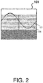
- FIG. 2 further depicts the pump assembly 100 unrolled to illustrate the pattern 121 (e.g., sinusoidal as shown) of the demarcation point 120 within the stator assembly 101.
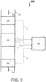
- FIG. 3 depicts a pump system 300 according to one or more embodiments.
- the pump system 300 comprises a conduit 301, a fluid 302, a pump assembly 310 (e.g., a pump assembly 100 of FIG. 1 ), a controller 320, and one or more sensors, such as an input sensor 330 and an output sensor 340 as shown.
- the conduit 301 is channel for conveying the fluid 302, and can be made of metal, plastic, fiber, fired clay, etc.
- the fluid 302 can be any liquid or gas capable of being pumped from one volume to another.
- the pump assembly 310 e.g., a pump assembly 100 of FIG. 1
- the controller 320, and the one or more sensors can be electrically coupled to communicate electrical signals there between.
- the controller 320 comprises a processor, a memory, and/or any processing hardware, software, or combination of hardware and software utilized by the pumping system 300 to carry out computer readable program instructions by performing arithmetical, logical, and/or input/output operations.
- the processor can comprise one or more central processing units (CPU(s)), also referred to as processing circuits, coupled via a system bus to the memory and various other internal or external components (e.g., the one or more sensors).
- the memory can include a read only memory (ROM) and a random access memory (RAM).
- the one or more sensors can be an electro-mechanical component that detects events in the conduit 301 and generates an electrical signal as a function of the events (e.g., generates an electrical signal in response to detecting a state of the fluid 302).
- the one or more sensors can utilize software and/or firmware to carry out operations particular thereto.
- the pump assembly 310 causes the fluid 302 to flow through the conduit 301.
- FIG. 4 depicts a process flow 400 of the pumping system 300 according to one or more embodiments.
- the process flow 400 begins at block 410, where the controller 320 provides a waveform at a frequency to a pump assembly 310 to drive a rotation of a piston assembly of the pump assembly 310.
- the waveform can be any waveform, such as square, sinusoidal, etc., where the frequency corresponds to a rotational speed and an amplitude corresponds to a translation of the piston assembly.
- the controller 320 increases an amplitude of the waveform to drive a translation of the piston assembly.
- the increase can be gradual to corresponding engage a pump action of the fluid 302 from zero to maximum.
- the controller 320 determines a flow rate of the fluid 302.
- the flow rate can be determined by the controller 320 based on the waveform itself and/or feedback information received by the one or more sensors. If the flow rate is not a desired value, the controller alter the waveform. For instance, the process flow 400 can proceed to block 440 (via arrow E), where the controller 320 can adjust (increase or decrease) the amplitude. Further, the process flow 400 can proceed to block 450 (via arrow F), where the controller 320 can adjust (increase or decrease) the frequency. The process flow 400 can then return to decision block 430.
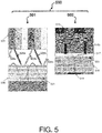
- FIG. 5 depicts a pump assembly 500 with two ports according.
- the pump assembly 500 includes a stator assembly 501 and a piston assembly 502. While shown separate for ease of explanation, the piston assembly 502 can be positioned within the stator assembly 501.
- the pump assembly 500 is an example and is not intended to suggest any limitation as to the scope of use or operability of embodiments described herein (indeed additional or alternative components and/or implementations may be used). Further, while single items are illustrated for items of the pump assembly 500, these representations are not intended to be limiting and thus, any item may represent a plurality of items.
- the stator assembly 501 includes a rotary winding 505, a linear winding 506, and a plurality of stator ports.
- the plurality of stator ports can comprise at least an inlet stator port 508a, an inlet stator port 508b, an outlet stator port 509a, and an outlet stator port 509b.
- the linear winding 506 translates the piston assembly 502 along a lengthwise axis of the stator assembly 501 (e.g., provides a linear stroke).
- the rotary winding 505 rotates the piston assembly 502 about the lengthwise axis of the stator assembly 501 (e.g., provides a clockwise and/or counterclockwise rotation).
- the piston assembly 502 includes a rotary armature 515 and a linear armature 516, along with an inner fluid vane 517 and a plurality of piston ports.
- the plurality of piston ports can include pressure ports 518a, 518b and a piston port 519 connected by the inner fluid vane 517.
- the pump assembly 500 provides rotation and/or translation rod action.
- the plurality of piston ports of the piston assembly 502 when properly commutated, can pump a working fluid from the inlet stator ports 508a, 508b to the outlet stator ports 509a, 509b incorporated into the stator assembly 501.
- the stator assembly 501 acts as a piston cylinder and has at least a dual set of windings (e.g., the rotary winding 505 and the linear winding 506) that interact with the piston magnets (e.g., the rotary armature 515 and the linear armature 516) to create a pumping motion.
- FIG. 5 includes a demarcation point 520 that is fixed arbitrarily to the piston assembly 502.
- the demarcation point 520 follows a pattern 521 within the stator assembly 501.
- FIG. 5 further depicts the stator assembly 501 unrolled to illustrate the pattern 521 (e.g., sinusoidal as shown) of the demarcation point 520.
- FIG. 6 depicts a pump assembly with dual sides according to one or more embodiments.
- the pump assembly 600 includes a stator assembly 601 and a piston assembly 602. While shown separate for ease of explanation, the piston assembly 602 can be positioned within the stator assembly 601.
- the pump assembly 600 is an example and is not intended to suggest any limitation as to the scope of use or operability of embodiments described herein (indeed additional or alternative components and/or implementations may be used). Further, while single items are illustrated for items of the pump assembly 600, these representations are not intended to be limiting and thus, any item may represent a plurality of items.
- the stator assembly 601 includes a rotary winding 605, a linear winding 606, and a plurality of stator ports.
- the plurality of stator ports can comprise at least an inlet stator port 608a, an inlet stator port 608b, an outlet stator port 609a, and an outlet stator port 609b.
- the linear winding 606 translates the piston assembly 602 along a lengthwise axis of the stator assembly 601 (e.g., provides a linear stroke).
- the rotary winding 605 rotates the piston assembly 602 about the lengthwise axis of the stator assembly 601 (e.g., provides a clockwise and/or counterclockwise rotation).
- the piston assembly 602 includes a rotary armature 615 and a linear armature 616, along with an inner fluid vanes 617a, an inner fluid vanes 617b, and a plurality of piston ports.
- the plurality of piston ports can include pressure ports 618a, 618b and piston ports 619a, 619b connected by the inner fluid vanes 617a, 617b, respectively.
- the pump assembly 600 provides rotation and/or translation rod action.
- the plurality of piston ports of the piston assembly 602 when properly commutated, can pump a working fluid from the inlet stator ports 608a, 608b to the outlet stator ports 609a, 609b incorporated into the stator assembly 601.
- the stator assembly 601 acts as a piston cylinder and has at least a dual set of windings (e.g., the rotary winding 605 and the linear winding 606) that interact with the piston magnets (e.g., the rotary armature 615 and the linear armature 616) to create a duel pumping motion.
- FIG. 6 further depicts the stator assembly 601 unrolled to illustrate the pattern 621 (e.g., sinusoidal as shown) of the demarcation point 620.
Landscapes
- Engineering & Computer Science (AREA)
- Mechanical Engineering (AREA)
- General Engineering & Computer Science (AREA)
- Physics & Mathematics (AREA)
- Fluid Mechanics (AREA)
- Power Engineering (AREA)
- Details And Applications Of Rotary Liquid Pumps (AREA)
- Reciprocating Pumps (AREA)
- Linear Motors (AREA)
Abstract
Description
- Typical pumping systems for engine injection applications require a motor mounted to a conventional pump that is not weight optimal. Failure modes of these conventional pumps are dominated by moving components, e.g., bearings that wear out, valves that clog/leak, etc., that if eliminated would significantly increase reliability. Thus, what is needed is a highly accurate, reliable, and compact variable displacement pumping system.
- In accordance with one or more embodiments, a pump assembly is provided. The pump assembly including a stator assembly. The stator assembly including a rotary winding and a linear winding. The pump assembly including a piston assembly positioned within the stator assembly. The piston assembly translates along a lengthwise axis of the stator assembly and rotates about the lengthwise axis of the stator assembly to create a pumping action.
- In accordance with one or more embodiments or the above pump assembly embodiment, the piston assembly can include a linear armature and a rotary armature.
- In accordance with one or more embodiments or any of the above pump assembly embodiments, the stator assembly can act as a piston cylinder within which the piston assembly translates in accordance with the linear winding interacting with the linear armature and rotates in accordance with the rotary winding interacting with the rotary armature to create the pumping action.
- In accordance with one or more embodiments or any of the above pump assembly embodiments, the stator assembly can include a plurality of stator ports, the plurality of stator ports including an inlet stator port and an outlet stator port.
- In accordance with one or more embodiments or any of the above pump assembly embodiments, the pumping action can pump a working fluid from the inlet stator port to the outlet stator port as the piston assembly translates and rotates within the stator assembly.
- In accordance with one or more embodiments or any of the above pump assembly embodiments, the piston assembly can include a plurality of piston ports and an inner fluid vane, the plurality of piston ports including a pressure port and a piston port connected by the inner fluid vane.
- In accordance with one or more embodiments or any of the above pump assembly embodiments, the plurality of piston ports can include a second pressure port connected to the piston port by the inner fluid vane.
- In accordance with one or more embodiments or any of the above pump assembly embodiments, the piston assembly can include a second inner fluid vane, the plurality of piston ports including a second pressure port and a second piston port connected by the second inner fluid vane.
- In accordance with one or more embodiments or any of the above pump assembly embodiments, the pump assembly can be electrically coupled to a controller, and the pump assembly can receive a waveform that drives the rotary winding and the linear winding.
- In accordance with one or more embodiments or any of the above pump assembly embodiments, an amplitude of the waveform can drive the translation of the piston assembly.
- In accordance with one or more embodiments or any of the above pump assembly embodiments, a frequency of the waveform can drive the rotation of the piston assembly.
- In accordance with one or more embodiments, the pumping system is provided. The pumping system includes a pump assembly. The pump assembly includes a stator assembly and a piston assembly. The stator assembly includes a rotary winding and a linear winding. The piston assembly is positioned within the stator assembly. The pumping system includes a controller electrically coupled to the pump assembly. The controller provides a waveform that drives the rotary winding and the linear winding.
- In accordance with one or more embodiments or the above pumping system embodiment, the piston assembly can translate along a lengthwise axis of the stator assembly and can rotate about the lengthwise axis of the stator assembly to create a pumping action.
- In accordance with one or more embodiments or any of the above pumping system embodiments, the piston assembly can include a linear armature and a rotary armature.
- In accordance with one or more embodiments or any of the above pumping system embodiments, the stator assembly can act as a piston cylinder within which the piston assembly translates in accordance with the linear winding interacting with the linear armature and rotates in accordance with the rotary winding interacting with the rotary armature to create the pumping action.
- In accordance with one or more embodiments or any of the above pumping system embodiments, the stator assembly can include a plurality of stator ports, the plurality of stator ports including an inlet stator port and an outlet stator port.
- In accordance with one or more embodiments or any of the above pumping system embodiments, the pumping action can pump a working fluid from the inlet stator port to the outlet stator port as the piston assembly translates and rotates within the stator assembly.
- In accordance with one or more embodiments or any of the above pumping system embodiments, the piston assembly can include a plurality of piston ports and an inner fluid vane, the plurality of piston ports including a pressure port and a piston port connected by the inner fluid vane.
- In accordance with one or more embodiments or any of the above pumping system embodiments, the plurality of piston ports can include a second pressure port connected to the piston port by the inner fluid vane.
- In accordance with one or more embodiments or any of the above pumping system embodiments, the piston assembly can include a second inner fluid vane, the plurality of piston ports including a second pressure port and a second piston port connected by the second inner fluid vane.
- The following descriptions should not be considered limiting in any way. With reference to the accompanying drawings, like elements are numbered alike:
-
FIG. 1 depicts a pump assembly according to one or more embodiments; -
FIG. 2 depicts an unrolled pump assembly according to one or more embodiments; -
FIG. 3 depicts a pump system according to one or more embodiments; -
FIG. 4 depicts a process flow of a pump system according to one or more embodiments; -
FIG. 5 depicts a pump assembly with two ports according to one or more embodiments; and -
FIG. 6 depicts a pump assembly with dual sides according to one or more embodiments. - A detailed description of one or more embodiments of the disclosed apparatus and method are presented herein by way of exemplification and not limitation with reference to the Figures.
- In accordance with one or more embodiments, a variable displacement pumping system and/or a valve-less variable displacement pump assembly (herein referred to as a pumping system and/or a pump assembly) is provided. The pump includes a stator assembly and a piston assembly. The stator assembly includes a rotary winding, a linear winding, and stator ports. The piston assembly is positioned within the stator assembly. The linear winding translates the piston assembly along a lengthwise axis of the stator assembly. The rotary winding rotates the piston assembly about the lengthwise axis of the stator assembly.
- The technical effects and benefits of the pump assembly described herein include eliminating moving parts to increase an overall system reliability, while increasing compactness, and providing a displacement with an infinite variable and metering accuracy a highly accurate, reliable, and compact highly compact and limited by the commutation sensors.
-
FIG. 1 depicts apump assembly 100 according to one or more embodiments. Thepump assembly 100 includes astator assembly 101 and apiston assembly 102. While shown separate for ease of explanation, thepiston assembly 102 can be positioned within thestator assembly 101. Thepump assembly 100 is an example and is not intended to suggest any limitation as to the scope of use or operability of embodiments described herein (indeed additional or alternative components and/or implementations may be used). Further, while single items are illustrated for items of thepump assembly 100, these representations are not intended to be limiting and thus, any item may represent a plurality of items. - The
stator assembly 101 includes arotary winding 105, alinear winding 106, and a plurality of stator ports. The plurality of stator ports can comprise at least aninlet stator port 108 and anoutlet stator port 109. Thelinear winding 106 translates thepiston assembly 102 along alengthwise axis 110 of the stator assembly 101 (e.g., provides a linear stroke 111). Therotary winding 105 rotates thepiston assembly 102 about thelengthwise axis 110 of the stator assembly 101 (e.g., provides a clockwise and/or counterclockwise rotation 112). - The
piston assembly 102 includes arotary armature 115 and alinear armature 116, along with aninner fluid vane 117 and a plurality of piston ports. The plurality of piston ports can include apressure port 118 and apiston port 119 connected by theinner fluid vane 117. - In accordance with one or more embodiments, the
pump assembly 100 provides rotation and/or translation rod action. For instance, the plurality of piston ports of thepiston assembly 102, when properly commutated, can pump a working fluid from theinlet stator port 108 to theoutlet stator port 109 incorporated into thestator assembly 101. Thestator assembly 101 acts as a piston cylinder and has at least a dual set of windings (e.g., the rotary winding 105 and the linear winding 106) that interact with the piston magnets (e.g., therotary armature 115 and the linear armature 116) to create a pumping motion. By way of example and to assist with understanding the pumping motion,FIG. 1 includes ademarcation point 120 that is fixed arbitrarily to thepiston assembly 102. In turn, as thepiston assembly 102 translates and rotates, thedemarcation point 120 follows apattern 121 within thestator assembly 101. In accordance with one or more embodiments,FIG. 2 further depicts thepump assembly 100 unrolled to illustrate the pattern 121 (e.g., sinusoidal as shown) of thedemarcation point 120 within thestator assembly 101. -
FIG. 3 depicts apump system 300 according to one or more embodiments. Thepump system 300 comprises aconduit 301, a fluid 302, a pump assembly 310 (e.g., apump assembly 100 ofFIG. 1 ), acontroller 320, and one or more sensors, such as aninput sensor 330 and anoutput sensor 340 as shown. Theconduit 301 is channel for conveying the fluid 302, and can be made of metal, plastic, fiber, fired clay, etc. The fluid 302 can be any liquid or gas capable of being pumped from one volume to another. The pump assembly 310 (e.g., apump assembly 100 ofFIG. 1 ), thecontroller 320, and the one or more sensors can be electrically coupled to communicate electrical signals there between. - The
controller 320 comprises a processor, a memory, and/or any processing hardware, software, or combination of hardware and software utilized by thepumping system 300 to carry out computer readable program instructions by performing arithmetical, logical, and/or input/output operations. The processor can comprise one or more central processing units (CPU(s)), also referred to as processing circuits, coupled via a system bus to the memory and various other internal or external components (e.g., the one or more sensors). The memory can include a read only memory (ROM) and a random access memory (RAM). - The one or more sensors can be an electro-mechanical component that detects events in the
conduit 301 and generates an electrical signal as a function of the events (e.g., generates an electrical signal in response to detecting a state of the fluid 302). The one or more sensors can utilize software and/or firmware to carry out operations particular thereto. - In an example operation, the
pump assembly 310, as controlled by the controller 320 (as shown by arrow A), causes the fluid 302 to flow through theconduit 301. The components of thepump assembly 310, along with theinput sensor 330 and theoutput sensor 340, can provide feedback information (as shown by arrows B, C, and D) to thecontroller 320 so that thecontroller 320 can adjust the operation of thepump assembly 310. -
FIG. 4 depicts aprocess flow 400 of thepumping system 300 according to one or more embodiments. Theprocess flow 400 begins atblock 410, where thecontroller 320 provides a waveform at a frequency to apump assembly 310 to drive a rotation of a piston assembly of thepump assembly 310. The waveform can be any waveform, such as square, sinusoidal, etc., where the frequency corresponds to a rotational speed and an amplitude corresponds to a translation of the piston assembly. - At
block 410, thecontroller 320 increases an amplitude of the waveform to drive a translation of the piston assembly. The increase can be gradual to corresponding engage a pump action of the fluid 302 from zero to maximum. - At
block 430, thecontroller 320 determines a flow rate of thefluid 302. The flow rate can be determined by thecontroller 320 based on the waveform itself and/or feedback information received by the one or more sensors. If the flow rate is not a desired value, the controller alter the waveform. For instance, theprocess flow 400 can proceed to block 440 (via arrow E), where thecontroller 320 can adjust (increase or decrease) the amplitude. Further, theprocess flow 400 can proceed to block 450 (via arrow F), where thecontroller 320 can adjust (increase or decrease) the frequency. The process flow 400 can then return todecision block 430. - Turning now to
FIGS. 5-6 , the pumping system will now be further described according to one or more embodiments.FIG. 5 depicts apump assembly 500 with two ports according. Thepump assembly 500 includes astator assembly 501 and apiston assembly 502. While shown separate for ease of explanation, thepiston assembly 502 can be positioned within thestator assembly 501. Thepump assembly 500 is an example and is not intended to suggest any limitation as to the scope of use or operability of embodiments described herein (indeed additional or alternative components and/or implementations may be used). Further, while single items are illustrated for items of thepump assembly 500, these representations are not intended to be limiting and thus, any item may represent a plurality of items. - The
stator assembly 501 includes a rotary winding 505, a linear winding 506, and a plurality of stator ports. The plurality of stator ports can comprise at least aninlet stator port 508a, aninlet stator port 508b, anoutlet stator port 509a, and anoutlet stator port 509b. The linear winding 506 translates thepiston assembly 502 along a lengthwise axis of the stator assembly 501 (e.g., provides a linear stroke). The rotary winding 505 rotates thepiston assembly 502 about the lengthwise axis of the stator assembly 501 (e.g., provides a clockwise and/or counterclockwise rotation). - The
piston assembly 502 includes arotary armature 515 and alinear armature 516, along with aninner fluid vane 517 and a plurality of piston ports. The plurality of piston ports can includepressure ports piston port 519 connected by theinner fluid vane 517. - In accordance with one or more embodiments, the
pump assembly 500 provides rotation and/or translation rod action. For instance, the plurality of piston ports of thepiston assembly 502, when properly commutated, can pump a working fluid from theinlet stator ports outlet stator ports stator assembly 501. Thestator assembly 501 acts as a piston cylinder and has at least a dual set of windings (e.g., the rotary winding 505 and the linear winding 506) that interact with the piston magnets (e.g., therotary armature 515 and the linear armature 516) to create a pumping motion. By way of example and to assist with understanding the pumping motion,FIG. 5 includes ademarcation point 520 that is fixed arbitrarily to thepiston assembly 502. In turn, as thepiston assembly 502 translates and rotates, thedemarcation point 520 follows apattern 521 within thestator assembly 501. In accordance with one or more embodiments,FIG. 5 further depicts thestator assembly 501 unrolled to illustrate the pattern 521 (e.g., sinusoidal as shown) of thedemarcation point 520. -
FIG. 6 depicts a pump assembly with dual sides according to one or more embodiments. Thepump assembly 600 includes astator assembly 601 and apiston assembly 602. While shown separate for ease of explanation, thepiston assembly 602 can be positioned within thestator assembly 601. Thepump assembly 600 is an example and is not intended to suggest any limitation as to the scope of use or operability of embodiments described herein (indeed additional or alternative components and/or implementations may be used). Further, while single items are illustrated for items of thepump assembly 600, these representations are not intended to be limiting and thus, any item may represent a plurality of items. - The
stator assembly 601 includes a rotary winding 605, a linear winding 606, and a plurality of stator ports. The plurality of stator ports can comprise at least aninlet stator port 608a, aninlet stator port 608b, anoutlet stator port 609a, and anoutlet stator port 609b. The linear winding 606 translates thepiston assembly 602 along a lengthwise axis of the stator assembly 601 (e.g., provides a linear stroke). The rotary winding 605 rotates thepiston assembly 602 about the lengthwise axis of the stator assembly 601 (e.g., provides a clockwise and/or counterclockwise rotation). - The
piston assembly 602 includes arotary armature 615 and alinear armature 616, along with aninner fluid vanes 617a, aninner fluid vanes 617b, and a plurality of piston ports. The plurality of piston ports can includepressure ports inner fluid vanes - In accordance with one or more embodiments, the
pump assembly 600 provides rotation and/or translation rod action. For instance, the plurality of piston ports of thepiston assembly 602, when properly commutated, can pump a working fluid from theinlet stator ports outlet stator ports stator assembly 601. Thestator assembly 601 acts as a piston cylinder and has at least a dual set of windings (e.g., the rotary winding 605 and the linear winding 606) that interact with the piston magnets (e.g., therotary armature 615 and the linear armature 616) to create a duel pumping motion. By way of example and to assist with understanding the pumping motion,FIG. 6 includes ademarcation point 620 that is fixed arbitrarily to thepiston assembly 602. In turn, as thepiston assembly 602 translates and rotates, thedemarcation point 620 follows apattern 621 within thestator assembly 601. In accordance with one or more embodiments,FIG. 6 further depicts thestator assembly 601 unrolled to illustrate the pattern 621 (e.g., sinusoidal as shown) of thedemarcation point 620. - The term "about" is intended to include the degree of error associated with measurement of the particular quantity based upon the equipment available at the time of filing the application. For example, "about" can include a range of ± 8% or 5%, or 2% of a given value.
- The terminology used herein is for the purpose of describing particular embodiments only and is not intended to be limiting of the present disclosure. As used herein, the singular forms "a", "an" and "the" are intended to include the plural forms as well, unless the context clearly indicates otherwise. It will be further understood that the terms "comprises" and/or "comprising," when used in this specification, specify the presence of stated features, integers, steps, operations, elements, and/or components, but do not preclude the presence or addition of one or more other features, integers, steps, operations, element components, and/or groups thereof.
- While the present disclosure has been described with reference to an exemplary embodiment or embodiments, it will be understood by those skilled in the art that various changes may be made and equivalents may be substituted for elements thereof without departing from the scope of the present disclosure. In addition, many modifications may be made to adapt a particular situation or material to the teachings of the present disclosure without departing from the essential scope thereof. Therefore, it is intended that the present disclosure not be limited to the particular embodiment disclosed as the best mode contemplated for carrying out this present disclosure, but that the present disclosure will include all embodiments falling within the scope of the claims.
Claims (15)
- A pump assembly comprising:a stator assembly (101) comprising a rotary winding (105) and a linear winding (106); anda piston assembly (102) positioned within the stator assembly; andwherein the piston assembly translates along a lengthwise axis of the stator assembly and rotates about the lengthwise axis of the stator assembly to create a pumping action.
- The pump assembly of claim 1, wherein the piston assembly comprises a linear armature (116) and a rotary armature (115).
- The pump assembly of claim 2, wherein the stator assembly acts as a piston cylinder within which the piston assembly translates in accordance with the linear winding interacting with the linear armature and rotates in accordance with the rotary winding interacting with the rotary armature to create the pumping action.
- The pump assembly of claim 1, 2 or 3, wherein the stator assembly comprises a plurality of stator ports, the plurality of stator ports comprising an inlet stator port (108) and an outlet stator port (109).
- The pump assembly of claim 4, wherein the pumping action pumps a working fluid from the inlet stator port to the outlet stator port as the piston assembly translates and rotates within the stator assembly.
- The pump assembly of any preceding claim, wherein the piston assembly comprises a plurality of piston ports and an inner fluid vane (117), the plurality of piston ports comprising a pressure port (118) and a piston port (119) connected by the inner fluid vane.
- The pump assembly of claim 6, wherein the plurality of piston ports comprises a second pressure port connected to the piston port by the inner fluid vane.
- The pump assembly of claim 6 or 7, wherein the piston assembly comprises a second inner fluid vane, the plurality of piston ports comprising a second pressure port and a second piston port connected by the second inner fluid vane.
- The pump assembly of claim 6, 7 or 8, wherein the pump assembly is electrically coupled to a controller (320), and
wherein the pump assembly receives a waveform that drives the rotary winding and the linear winding. - The pump assembly of claim 9, wherein an amplitude of the waveform drives the translation or a rotation of the piston assembly.
- A pumping system comprising:a pump assembly (100) comprising a stator assembly (101) and a piston assembly (102), the stator assembly comprising a rotary winding (105) and a linear winding (106), and the piston assembly positioned within the stator assembly; anda controller (320) electrically coupled to the pump assembly to provide a waveform that drives the rotary winding and the linear winding.
- The pump system of claim 11, wherein the piston assembly translates along a lengthwise axis of the stator assembly and rotates about the lengthwise axis of the stator assembly to create a pumping action.
- The pump system of claim 11 or 12, wherein the piston assembly comprises a linear armature (116) and a rotary armature (115).
- The pump system of claim 11, 12 or 13, wherein the stator assembly comprises a plurality of stator ports, the plurality of stator ports comprising an inlet stator port (108) and an outlet stator port (109).
- The pump system of any of claims 11 to 14, wherein the piston assembly comprises a plurality of piston ports and an inner fluid vane (117), the plurality of piston ports comprising a pressure port (118) and a piston port (119) connected by the inner fluid vane.
Applications Claiming Priority (1)
| Application Number | Priority Date | Filing Date | Title |
|---|---|---|---|
| US15/875,103 US10962014B2 (en) | 2018-01-19 | 2018-01-19 | Valve-less variable displacement pump |
Publications (2)
| Publication Number | Publication Date |
|---|---|
| EP3514379A1 true EP3514379A1 (en) | 2019-07-24 |
| EP3514379B1 EP3514379B1 (en) | 2022-07-06 |
Family
ID=65041684
Family Applications (1)
| Application Number | Title | Priority Date | Filing Date |
|---|---|---|---|
| EP19152606.0A Active EP3514379B1 (en) | 2018-01-19 | 2019-01-18 | Valveless variable displacement pump |
Country Status (2)
| Country | Link |
|---|---|
| US (1) | US10962014B2 (en) |
| EP (1) | EP3514379B1 (en) |
Cited By (1)
| Publication number | Priority date | Publication date | Assignee | Title |
|---|---|---|---|---|
| CN111577569A (en) * | 2020-04-16 | 2020-08-25 | 徐炳祥 | Liquid compression device for butt joint of pipelines |
Citations (4)
| Publication number | Priority date | Publication date | Assignee | Title |
|---|---|---|---|---|
| US3602614A (en) * | 1969-02-26 | 1971-08-31 | Licentia Gmbh | Positive displacement pump |
| US5924975A (en) * | 1995-08-30 | 1999-07-20 | International Business Machines Corporation | Linear pump |
| US20010043864A1 (en) * | 2000-03-07 | 2001-11-22 | Teruo Maruyama | Fluid discharge device and fluid discharge method |
| CN1707925A (en) * | 2004-06-04 | 2005-12-14 | 刘星达 | Spiralling motor |
Family Cites Families (11)
| Publication number | Priority date | Publication date | Assignee | Title |
|---|---|---|---|---|
| US1034592A (en) | 1911-10-23 | 1912-08-06 | George J Dourte | Valveless pump. |
| US4008003A (en) * | 1975-06-27 | 1977-02-15 | Pinkerton Harry E | Valveless positive displacement pump |
| US5961303A (en) * | 1997-11-18 | 1999-10-05 | King; Kenyon M. | Positive displacement dispensing pump system |
| US6290640B1 (en) * | 1999-11-02 | 2001-09-18 | International Business Machines Corporation | Uncoupled rotary linear pump |
| SE522949C2 (en) * | 2000-04-11 | 2004-03-16 | Saab Ab | Electro-hydraulic actuator |
| KR100352937B1 (en) * | 2000-05-20 | 2002-09-16 | 미래산업 주식회사 | Linear Electric Motor of Rotational and Linear Movement Type |
| EP1813412B1 (en) * | 2003-08-25 | 2011-03-02 | Husky Injection Molding Systems Ltd. | Drive assembly for rotating and translating a shaft |
| US7798783B2 (en) * | 2006-04-06 | 2010-09-21 | Micropump, Inc. | Magnetically driven valveless piston pumps |
| US9004883B2 (en) * | 2011-04-01 | 2015-04-14 | Gm Global Technology Operations, Llc | Low noise high efficiency solenoid pump |
| FR3008746B1 (en) | 2013-07-22 | 2016-12-09 | Eveon | OSCILLO-ROTATING SUBASSEMBLY FOR PUMPING A FLUID AND OSCILLO-ROTATING PUMPING DEVICE |
| WO2016198554A1 (en) * | 2015-06-09 | 2016-12-15 | Universiteit Gent | Free piston device |
-
2018
- 2018-01-19 US US15/875,103 patent/US10962014B2/en active Active
-
2019
- 2019-01-18 EP EP19152606.0A patent/EP3514379B1/en active Active
Patent Citations (4)
| Publication number | Priority date | Publication date | Assignee | Title |
|---|---|---|---|---|
| US3602614A (en) * | 1969-02-26 | 1971-08-31 | Licentia Gmbh | Positive displacement pump |
| US5924975A (en) * | 1995-08-30 | 1999-07-20 | International Business Machines Corporation | Linear pump |
| US20010043864A1 (en) * | 2000-03-07 | 2001-11-22 | Teruo Maruyama | Fluid discharge device and fluid discharge method |
| CN1707925A (en) * | 2004-06-04 | 2005-12-14 | 刘星达 | Spiralling motor |
Cited By (1)
| Publication number | Priority date | Publication date | Assignee | Title |
|---|---|---|---|---|
| CN111577569A (en) * | 2020-04-16 | 2020-08-25 | 徐炳祥 | Liquid compression device for butt joint of pipelines |
Also Published As
| Publication number | Publication date |
|---|---|
| US20190226484A1 (en) | 2019-07-25 |
| US10962014B2 (en) | 2021-03-30 |
| EP3514379B1 (en) | 2022-07-06 |
Similar Documents
| Publication | Publication Date | Title |
|---|---|---|
| CA2795538C (en) | Phase shift controller for a reciprocating pump system | |
| US11959497B2 (en) | Method for determining operational parameters of a blood pump | |
| US4990058A (en) | Pumping apparatus and pump control apparatus and method | |
| US5312233A (en) | Linear liquid dispensing pump for dispensing liquid in nanoliter volumes | |
| US5456581A (en) | Control system for a multi-piston pump with solenoid valves for the production of constant outlet pressure flow | |
| US20080012522A1 (en) | Method and apparatus for utilizing commutation sensors for speed and position control | |
| US11118577B2 (en) | Metering pump and method for controlling a metering pump | |
| EP3514379B1 (en) | Valveless variable displacement pump | |
| CA2948018A1 (en) | Lift apparatus for driving a downhole reciprocating pump | |
| WO2014093452A1 (en) | Dielectric sensor arrangement and method for swashplate angular position detection | |
| CN106555738B (en) | device for determining pressure | |
| CN103775321B (en) | Hydraulic resistance balance formula servocontrol volume adjustable hydraulic pump | |
| CN104912856B (en) | Double oil cylinder synchronous servo control system devices | |
| EP4528103A2 (en) | Mechanism for electronic adjustment of flows in fixed displacement pump | |
| US9890777B2 (en) | Delay-minimized detection of an auxiliary control variable | |
| EP3227554B1 (en) | A diaphragm pump for dosing a fluid and an according method | |
| US10495218B2 (en) | Variable displacement hydraulic pump with torque sensing and method thereof | |
| CN203685538U (en) | Hydraulic balanced type servo control volume-adjustable hydraulic pump | |
| US11644032B2 (en) | Pump with detection of absolute angle of rotation | |
| EP4180069A1 (en) | System for pumping a medical fluid | |
| JPS6321370A (en) | Pulsation-free constant flow rate pump | |
| IE58602B1 (en) | Method for detecting step losses in stepping-motor-driven adjusting devices | |
| NL2004979C2 (en) | Phase shift controller for a reciprocating pump system. | |
| CN112628220B (en) | Servo oil source of pressure testing machine | |
| US20240352952A1 (en) | Control circuitry and pump system |
Legal Events
| Date | Code | Title | Description |
|---|---|---|---|
| PUAI | Public reference made under article 153(3) epc to a published international application that has entered the european phase |
Free format text: ORIGINAL CODE: 0009012 |
|
| STAA | Information on the status of an ep patent application or granted ep patent |
Free format text: STATUS: THE APPLICATION HAS BEEN PUBLISHED |
|
| AK | Designated contracting states |
Kind code of ref document: A1 Designated state(s): AL AT BE BG CH CY CZ DE DK EE ES FI FR GB GR HR HU IE IS IT LI LT LU LV MC MK MT NL NO PL PT RO RS SE SI SK SM TR |
|
| AX | Request for extension of the european patent |
Extension state: BA ME |
|
| STAA | Information on the status of an ep patent application or granted ep patent |
Free format text: STATUS: REQUEST FOR EXAMINATION WAS MADE |
|
| 17P | Request for examination filed |
Effective date: 20191121 |
|
| RBV | Designated contracting states (corrected) |
Designated state(s): AL AT BE BG CH CY CZ DE DK EE ES FI FR GB GR HR HU IE IS IT LI LT LU LV MC MK MT NL NO PL PT RO RS SE SI SK SM TR |
|
| STAA | Information on the status of an ep patent application or granted ep patent |
Free format text: STATUS: EXAMINATION IS IN PROGRESS |
|
| 17Q | First examination report despatched |
Effective date: 20200417 |
|
| RIC1 | Information provided on ipc code assigned before grant |
Ipc: F04B 17/03 20060101ALI20201028BHEP Ipc: F04B 53/14 20060101ALI20201028BHEP Ipc: F04B 17/04 20060101ALI20201028BHEP Ipc: H02K 33/16 20060101ALI20201028BHEP Ipc: F04B 7/06 20060101AFI20201028BHEP |
|
| GRAP | Despatch of communication of intention to grant a patent |
Free format text: ORIGINAL CODE: EPIDOSNIGR1 |
|
| STAA | Information on the status of an ep patent application or granted ep patent |
Free format text: STATUS: GRANT OF PATENT IS INTENDED |
|
| INTG | Intention to grant announced |
Effective date: 20220131 |
|
| GRAS | Grant fee paid |
Free format text: ORIGINAL CODE: EPIDOSNIGR3 |
|
| GRAA | (expected) grant |
Free format text: ORIGINAL CODE: 0009210 |
|
| STAA | Information on the status of an ep patent application or granted ep patent |
Free format text: STATUS: THE PATENT HAS BEEN GRANTED |
|
| AK | Designated contracting states |
Kind code of ref document: B1 Designated state(s): AL AT BE BG CH CY CZ DE DK EE ES FI FR GB GR HR HU IE IS IT LI LT LU LV MC MK MT NL NO PL PT RO RS SE SI SK SM TR |
|
| REG | Reference to a national code |
Ref country code: AT Ref legal event code: REF Ref document number: 1503048 Country of ref document: AT Kind code of ref document: T Effective date: 20220715 Ref country code: CH Ref legal event code: EP |
|
| REG | Reference to a national code |
Ref country code: DE Ref legal event code: R096 Ref document number: 602019016577 Country of ref document: DE |
|
| REG | Reference to a national code |
Ref country code: IE Ref legal event code: FG4D |
|
| REG | Reference to a national code |
Ref country code: LT Ref legal event code: MG9D |
|
| REG | Reference to a national code |
Ref country code: NL Ref legal event code: MP Effective date: 20220706 |
|
| PG25 | Lapsed in a contracting state [announced via postgrant information from national office to epo] |
Ref country code: SE Free format text: LAPSE BECAUSE OF FAILURE TO SUBMIT A TRANSLATION OF THE DESCRIPTION OR TO PAY THE FEE WITHIN THE PRESCRIBED TIME-LIMIT Effective date: 20220706 Ref country code: RS Free format text: LAPSE BECAUSE OF FAILURE TO SUBMIT A TRANSLATION OF THE DESCRIPTION OR TO PAY THE FEE WITHIN THE PRESCRIBED TIME-LIMIT Effective date: 20220706 Ref country code: PT Free format text: LAPSE BECAUSE OF FAILURE TO SUBMIT A TRANSLATION OF THE DESCRIPTION OR TO PAY THE FEE WITHIN THE PRESCRIBED TIME-LIMIT Effective date: 20221107 Ref country code: NO Free format text: LAPSE BECAUSE OF FAILURE TO SUBMIT A TRANSLATION OF THE DESCRIPTION OR TO PAY THE FEE WITHIN THE PRESCRIBED TIME-LIMIT Effective date: 20221006 Ref country code: NL Free format text: LAPSE BECAUSE OF FAILURE TO SUBMIT A TRANSLATION OF THE DESCRIPTION OR TO PAY THE FEE WITHIN THE PRESCRIBED TIME-LIMIT Effective date: 20220706 Ref country code: LV Free format text: LAPSE BECAUSE OF FAILURE TO SUBMIT A TRANSLATION OF THE DESCRIPTION OR TO PAY THE FEE WITHIN THE PRESCRIBED TIME-LIMIT Effective date: 20220706 Ref country code: LT Free format text: LAPSE BECAUSE OF FAILURE TO SUBMIT A TRANSLATION OF THE DESCRIPTION OR TO PAY THE FEE WITHIN THE PRESCRIBED TIME-LIMIT Effective date: 20220706 Ref country code: FI Free format text: LAPSE BECAUSE OF FAILURE TO SUBMIT A TRANSLATION OF THE DESCRIPTION OR TO PAY THE FEE WITHIN THE PRESCRIBED TIME-LIMIT Effective date: 20220706 Ref country code: ES Free format text: LAPSE BECAUSE OF FAILURE TO SUBMIT A TRANSLATION OF THE DESCRIPTION OR TO PAY THE FEE WITHIN THE PRESCRIBED TIME-LIMIT Effective date: 20220706 |
|
| REG | Reference to a national code |
Ref country code: AT Ref legal event code: MK05 Ref document number: 1503048 Country of ref document: AT Kind code of ref document: T Effective date: 20220706 |
|
| PG25 | Lapsed in a contracting state [announced via postgrant information from national office to epo] |
Ref country code: PL Free format text: LAPSE BECAUSE OF FAILURE TO SUBMIT A TRANSLATION OF THE DESCRIPTION OR TO PAY THE FEE WITHIN THE PRESCRIBED TIME-LIMIT Effective date: 20220706 Ref country code: IS Free format text: LAPSE BECAUSE OF FAILURE TO SUBMIT A TRANSLATION OF THE DESCRIPTION OR TO PAY THE FEE WITHIN THE PRESCRIBED TIME-LIMIT Effective date: 20221106 Ref country code: HR Free format text: LAPSE BECAUSE OF FAILURE TO SUBMIT A TRANSLATION OF THE DESCRIPTION OR TO PAY THE FEE WITHIN THE PRESCRIBED TIME-LIMIT Effective date: 20220706 Ref country code: GR Free format text: LAPSE BECAUSE OF FAILURE TO SUBMIT A TRANSLATION OF THE DESCRIPTION OR TO PAY THE FEE WITHIN THE PRESCRIBED TIME-LIMIT Effective date: 20221007 |
|
| REG | Reference to a national code |
Ref country code: DE Ref legal event code: R097 Ref document number: 602019016577 Country of ref document: DE |
|
| PG25 | Lapsed in a contracting state [announced via postgrant information from national office to epo] |
Ref country code: SM Free format text: LAPSE BECAUSE OF FAILURE TO SUBMIT A TRANSLATION OF THE DESCRIPTION OR TO PAY THE FEE WITHIN THE PRESCRIBED TIME-LIMIT Effective date: 20220706 Ref country code: RO Free format text: LAPSE BECAUSE OF FAILURE TO SUBMIT A TRANSLATION OF THE DESCRIPTION OR TO PAY THE FEE WITHIN THE PRESCRIBED TIME-LIMIT Effective date: 20220706 Ref country code: DK Free format text: LAPSE BECAUSE OF FAILURE TO SUBMIT A TRANSLATION OF THE DESCRIPTION OR TO PAY THE FEE WITHIN THE PRESCRIBED TIME-LIMIT Effective date: 20220706 Ref country code: CZ Free format text: LAPSE BECAUSE OF FAILURE TO SUBMIT A TRANSLATION OF THE DESCRIPTION OR TO PAY THE FEE WITHIN THE PRESCRIBED TIME-LIMIT Effective date: 20220706 Ref country code: AT Free format text: LAPSE BECAUSE OF FAILURE TO SUBMIT A TRANSLATION OF THE DESCRIPTION OR TO PAY THE FEE WITHIN THE PRESCRIBED TIME-LIMIT Effective date: 20220706 |
|
| PLBE | No opposition filed within time limit |
Free format text: ORIGINAL CODE: 0009261 |
|
| STAA | Information on the status of an ep patent application or granted ep patent |
Free format text: STATUS: NO OPPOSITION FILED WITHIN TIME LIMIT |
|
| PG25 | Lapsed in a contracting state [announced via postgrant information from national office to epo] |
Ref country code: SK Free format text: LAPSE BECAUSE OF FAILURE TO SUBMIT A TRANSLATION OF THE DESCRIPTION OR TO PAY THE FEE WITHIN THE PRESCRIBED TIME-LIMIT Effective date: 20220706 Ref country code: EE Free format text: LAPSE BECAUSE OF FAILURE TO SUBMIT A TRANSLATION OF THE DESCRIPTION OR TO PAY THE FEE WITHIN THE PRESCRIBED TIME-LIMIT Effective date: 20220706 |
|
| 26N | No opposition filed |
Effective date: 20230411 |
|
| P01 | Opt-out of the competence of the unified patent court (upc) registered |
Effective date: 20230522 |
|
| PG25 | Lapsed in a contracting state [announced via postgrant information from national office to epo] |
Ref country code: AL Free format text: LAPSE BECAUSE OF FAILURE TO SUBMIT A TRANSLATION OF THE DESCRIPTION OR TO PAY THE FEE WITHIN THE PRESCRIBED TIME-LIMIT Effective date: 20220706 |
|
| PG25 | Lapsed in a contracting state [announced via postgrant information from national office to epo] |
Ref country code: SI Free format text: LAPSE BECAUSE OF FAILURE TO SUBMIT A TRANSLATION OF THE DESCRIPTION OR TO PAY THE FEE WITHIN THE PRESCRIBED TIME-LIMIT Effective date: 20220706 |
|
| REG | Reference to a national code |
Ref country code: CH Ref legal event code: PL |
|
| PG25 | Lapsed in a contracting state [announced via postgrant information from national office to epo] |
Ref country code: LU Free format text: LAPSE BECAUSE OF NON-PAYMENT OF DUE FEES Effective date: 20230118 |
|
| REG | Reference to a national code |
Ref country code: BE Ref legal event code: MM Effective date: 20230131 |
|
| PG25 | Lapsed in a contracting state [announced via postgrant information from national office to epo] |
Ref country code: LI Free format text: LAPSE BECAUSE OF NON-PAYMENT OF DUE FEES Effective date: 20230131 Ref country code: CH Free format text: LAPSE BECAUSE OF NON-PAYMENT OF DUE FEES Effective date: 20230131 |
|
| PG25 | Lapsed in a contracting state [announced via postgrant information from national office to epo] |
Ref country code: BE Free format text: LAPSE BECAUSE OF NON-PAYMENT OF DUE FEES Effective date: 20230131 |
|
| PG25 | Lapsed in a contracting state [announced via postgrant information from national office to epo] |
Ref country code: IT Free format text: LAPSE BECAUSE OF FAILURE TO SUBMIT A TRANSLATION OF THE DESCRIPTION OR TO PAY THE FEE WITHIN THE PRESCRIBED TIME-LIMIT Effective date: 20220706 Ref country code: IE Free format text: LAPSE BECAUSE OF NON-PAYMENT OF DUE FEES Effective date: 20230118 |
|
| PG25 | Lapsed in a contracting state [announced via postgrant information from national office to epo] |
Ref country code: MC Free format text: LAPSE BECAUSE OF FAILURE TO SUBMIT A TRANSLATION OF THE DESCRIPTION OR TO PAY THE FEE WITHIN THE PRESCRIBED TIME-LIMIT Effective date: 20220706 |
|
| PG25 | Lapsed in a contracting state [announced via postgrant information from national office to epo] |
Ref country code: MC Free format text: LAPSE BECAUSE OF FAILURE TO SUBMIT A TRANSLATION OF THE DESCRIPTION OR TO PAY THE FEE WITHIN THE PRESCRIBED TIME-LIMIT Effective date: 20220706 |
|
| PG25 | Lapsed in a contracting state [announced via postgrant information from national office to epo] |
Ref country code: BG Free format text: LAPSE BECAUSE OF FAILURE TO SUBMIT A TRANSLATION OF THE DESCRIPTION OR TO PAY THE FEE WITHIN THE PRESCRIBED TIME-LIMIT Effective date: 20220706 |
|
| PG25 | Lapsed in a contracting state [announced via postgrant information from national office to epo] |
Ref country code: BG Free format text: LAPSE BECAUSE OF FAILURE TO SUBMIT A TRANSLATION OF THE DESCRIPTION OR TO PAY THE FEE WITHIN THE PRESCRIBED TIME-LIMIT Effective date: 20220706 |
|
| PG25 | Lapsed in a contracting state [announced via postgrant information from national office to epo] |
Ref country code: CY Free format text: LAPSE BECAUSE OF FAILURE TO SUBMIT A TRANSLATION OF THE DESCRIPTION OR TO PAY THE FEE WITHIN THE PRESCRIBED TIME-LIMIT; INVALID AB INITIO Effective date: 20190118 |
|
| PG25 | Lapsed in a contracting state [announced via postgrant information from national office to epo] |
Ref country code: HU Free format text: LAPSE BECAUSE OF FAILURE TO SUBMIT A TRANSLATION OF THE DESCRIPTION OR TO PAY THE FEE WITHIN THE PRESCRIBED TIME-LIMIT; INVALID AB INITIO Effective date: 20190118 |
|
| PG25 | Lapsed in a contracting state [announced via postgrant information from national office to epo] |
Ref country code: TR Free format text: LAPSE BECAUSE OF FAILURE TO SUBMIT A TRANSLATION OF THE DESCRIPTION OR TO PAY THE FEE WITHIN THE PRESCRIBED TIME-LIMIT Effective date: 20220706 |
|
| PGFP | Annual fee paid to national office [announced via postgrant information from national office to epo] |
Ref country code: GB Payment date: 20251220 Year of fee payment: 8 |
|
| PGFP | Annual fee paid to national office [announced via postgrant information from national office to epo] |
Ref country code: FR Payment date: 20251217 Year of fee payment: 8 |
|
| PGFP | Annual fee paid to national office [announced via postgrant information from national office to epo] |
Ref country code: DE Payment date: 20251217 Year of fee payment: 8 |