EP3514343A1 - Saddle-type vehicle - Google Patents
Saddle-type vehicle Download PDFInfo
- Publication number
- EP3514343A1 EP3514343A1 EP19152727.4A EP19152727A EP3514343A1 EP 3514343 A1 EP3514343 A1 EP 3514343A1 EP 19152727 A EP19152727 A EP 19152727A EP 3514343 A1 EP3514343 A1 EP 3514343A1
- Authority
- EP
- European Patent Office
- Prior art keywords
- pipe
- chamber
- vehicle
- outlet
- case
- Prior art date
- Legal status (The legal status is an assumption and is not a legal conclusion. Google has not performed a legal analysis and makes no representation as to the accuracy of the status listed.)
- Granted
Links
Images






Classifications
-
- F—MECHANICAL ENGINEERING; LIGHTING; HEATING; WEAPONS; BLASTING
- F01—MACHINES OR ENGINES IN GENERAL; ENGINE PLANTS IN GENERAL; STEAM ENGINES
- F01N—GAS-FLOW SILENCERS OR EXHAUST APPARATUS FOR MACHINES OR ENGINES IN GENERAL; GAS-FLOW SILENCERS OR EXHAUST APPARATUS FOR INTERNAL-COMBUSTION ENGINES
- F01N1/00—Silencing apparatus characterised by method of silencing
- F01N1/08—Silencing apparatus characterised by method of silencing by reducing exhaust energy by throttling or whirling
- F01N1/084—Silencing apparatus characterised by method of silencing by reducing exhaust energy by throttling or whirling the exhaust gases flowing through the silencer two or more times longitudinally in opposite directions, e.g. using parallel or concentric tubes
-
- F—MECHANICAL ENGINEERING; LIGHTING; HEATING; WEAPONS; BLASTING
- F01—MACHINES OR ENGINES IN GENERAL; ENGINE PLANTS IN GENERAL; STEAM ENGINES
- F01N—GAS-FLOW SILENCERS OR EXHAUST APPARATUS FOR MACHINES OR ENGINES IN GENERAL; GAS-FLOW SILENCERS OR EXHAUST APPARATUS FOR INTERNAL-COMBUSTION ENGINES
- F01N1/00—Silencing apparatus characterised by method of silencing
- F01N1/08—Silencing apparatus characterised by method of silencing by reducing exhaust energy by throttling or whirling
- F01N1/089—Silencing apparatus characterised by method of silencing by reducing exhaust energy by throttling or whirling using two or more expansion chambers in series
-
- F—MECHANICAL ENGINEERING; LIGHTING; HEATING; WEAPONS; BLASTING
- F01—MACHINES OR ENGINES IN GENERAL; ENGINE PLANTS IN GENERAL; STEAM ENGINES
- F01N—GAS-FLOW SILENCERS OR EXHAUST APPARATUS FOR MACHINES OR ENGINES IN GENERAL; GAS-FLOW SILENCERS OR EXHAUST APPARATUS FOR INTERNAL-COMBUSTION ENGINES
- F01N2470/00—Structure or shape of exhaust gas passages, pipes or tubes
- F01N2470/02—Tubes being perforated
-
- F—MECHANICAL ENGINEERING; LIGHTING; HEATING; WEAPONS; BLASTING
- F01—MACHINES OR ENGINES IN GENERAL; ENGINE PLANTS IN GENERAL; STEAM ENGINES
- F01N—GAS-FLOW SILENCERS OR EXHAUST APPARATUS FOR MACHINES OR ENGINES IN GENERAL; GAS-FLOW SILENCERS OR EXHAUST APPARATUS FOR INTERNAL-COMBUSTION ENGINES
- F01N2590/00—Exhaust or silencing apparatus adapted to particular use, e.g. for military applications, airplanes, submarines
- F01N2590/04—Exhaust or silencing apparatus adapted to particular use, e.g. for military applications, airplanes, submarines for motorcycles
Definitions
- the present invention relates to a straddled vehicle.
- Japanese Laid-Open Patent Publication No. 2009-248824 discloses a motorcycle including a silencer arranged between the engine and the rear wheel.
- the silencer disclosed in Japanese Laid-Open Patent Publication No. 2009-248824 includes a case, the inside of which is partitioned into a first, a second and a third expansion chamber, a first pipe that connects together the first expansion chamber and the second expansion chamber, a second pipe that connects together the second expansion chamber and the third expansion chamber, and a third pipe that connects together the third expansion chamber and the outside of the case.
- the first expansion chamber communicates with the exhaust pipe of the engine.
- the first pipe and the second pipe are arranged inside the case.
- the third pipe extends through the side surface of the case, and a portion of the third pipe protrudes out of the case.
- the exhaust gas from the engine expands gradually by flowing sequentially through the first expansion chamber, the second expansion chamber and the third expansion chamber. This reduces the environmental noise from the exhaust.
- the distance between the engine and the rear wheel tends to be relatively short, and the space between the engine and the rear wheel is small.
- the size of the silencer being large imposes tight constraints on designing the vehicle.
- simply reducing the size of the silencer will reduce the volumes of the expansion chambers, and it is then difficult to sufficiently reduce the environmental noise from the exhaust.
- the present inventor focused on the fact that the environmental noise from the exhaust can be generally classified into a low-frequency component and a high-frequency component, for each of which there is an effective silencing mechanism.
- the present inventor considered reducing the number of expansion chambers in the case, and instead providing expansion chambers of greater capacities than those of the conventional techniques. Then, it is possible to increase the degree by which the exhaust gas expands at a time even though the number of times the exhaust gas expands is reduced. Thus, it is possible to effectively reduce the low-frequency component.
- the present inventor considered arranging a fiber-based sound-absorbing material such as a glass wool in one expansion chamber. Then, it is possible to effectively reduce the high-frequency component.
- the present inventor thus found that it is possible to reduce the environmental noise from the exhaust without increasing the size of the silencer by using suitable silencing mechanisms for the low-frequency component and for the high-frequency component.
- the present invention is based on this finding.
- a straddled vehicle disclosed herein includes: an engine; a rear wheel arranged rearward of the engine; an exhaust pipe connected to the engine; and a silencer connected to the exhaust pipe, at least a portion of which is arranged rearward of the engine and forward of the rear wheel.
- the silencer includes a case, a partition wall, a first pipe, a second pipe, a fiber-based silencing material, a third pipe, and a fourth pipe. At least a portion of the case is arranged on a vehicle center line as the vehicle is seen from below.
- the partition wall is arranged inside the case and partitions the inside of the case into a first chamber and a second chamber.
- the first pipe has a first inlet through which an exhaust gas from the exhaust pipe flows into the first pipe, a first peripheral wall that is arranged in the first chamber and has a plurality of through holes, and a first outlet that is opened into the second chamber.
- the second pipe has a second inlet that is opened into the second chamber, and a second peripheral wall that is arranged in the first chamber and has a plurality of through holes.
- the fiber-based silencing material is arranged inside the first chamber and outside the first pipe and the second pipe.
- the third pipe has a third inlet that is arranged inside the second pipe, a third peripheral wall that is arranged inside the second pipe and inside the second chamber, and a third outlet that is opened toward an outside of the case.
- the fourth pipe has a fourth inlet that is arranged inside the second pipe, a fourth peripheral wall that is arranged inside the second pipe and inside the second chamber, and a fourth outlet that is opened toward the outside of the case.
- the inside of the case is partitioned into two chambers.
- By expanding the exhaust gas through the second chamber having a large volume it is possible to effectively reduce the low-frequency component of the environmental noise from the exhaust.
- through holes are formed in the first peripheral wall of the first pipe and the second peripheral wall of the second pipe, and the fiber-based silencing material is arranged inside the first chamber and outside the first pipe and the second pipe. Therefore, while the exhaust gas flows through the first pipe and the second pipe, it is possible to effectively reduce the high-frequency component of the environmental noise from the exhaust.
- the straddled vehicle described above includes two pipes (i.e., the third pipe and the fourth pipe) for emitting the exhaust gas out of the case. Therefore, as compared with a case where the exhaust gas is emitted out of the case by using one pipe, the sound to be emitted out of the case can be dispersed. With the straddled vehicle described above, these advantageous effects are synergistically combined together, and it is possible to reduce the environmental noise from the exhaust and reduce the size of the silencer.
- Another straddled vehicle disclosed herein includes: an engine; a rear wheel arranged rearward of the engine; an exhaust pipe connected to the engine; and a silencer connected to the exhaust pipe, at least a portion of which is arranged rearward of the engine and forward of the rear wheel.
- the silencer includes a case, a partition wall, a first pipe, a second pipe, an additional second pipe, a fiber-based silencing material, a third pipe, and a fourth pipe. At least a portion of the case is arranged on a vehicle center line as the vehicle is seen from below.
- the partition wall is arranged inside the case and partitions the inside of the case into a first chamber and a second chamber.
- the first pipe has a first inlet through which an exhaust gas from the exhaust pipe flows into the first pipe, a first peripheral wall that is arranged in the first chamber and has a plurality of through holes, and a first outlet that is opened into the second chamber.
- the second pipe has a second inlet that is opened into the second chamber, and a second peripheral wall that is arranged in the first chamber and has a plurality of through holes.
- the additional second pipe has an additional second inlet that is opened into the second chamber, and an additional second peripheral wall that is arranged in the first chamber and has a plurality of through holes.
- the fiber-based silencing material is arranged inside the first chamber and outside the first pipe, the second pipe and the additional second pipe.
- the third pipe has a third inlet that is arranged inside the second pipe, a third peripheral wall that is arranged inside the second pipe and inside the second chamber, and a third outlet that is opened toward an outside of the case.
- the fourth pipe has a fourth inlet that is arranged inside the additional second pipe, a fourth peripheral wall that is arranged inside the additional second pipe and inside the second chamber, and a fourth outlet that is opened toward the outside of the case.
- the inside of the case is partitioned into two chambers, and it is therefore possible to increase the volume of the second chamber without increasing the size of the case.
- By expanding the exhaust gas through the second chamber having a large volume it is possible to effectively reduce the low-frequency component of the environmental noise from the exhaust.
- through holes are formed in the first peripheral wall of the first pipe, the second peripheral wall of the second pipe and the additional second peripheral wall of the additional second pipe, and the fiber-based silencing material is arranged inside the first chamber and outside the first pipe, the second pipe and the additional second pipe.
- the straddled vehicle described above includes two pipes (i.e., the third pipe and the fourth pipe) for emitting the exhaust gas out of the case.
- the case has a bottom wall.
- the third pipe and the fourth pipe are connected to the bottom wall.
- one of the third outlet and the fourth outlet is located leftward of a middle of the case in a vehicle width direction.
- the other one of the third outlet and the fourth outlet is located rightward of the middle of the case in the vehicle width direction.
- the sound discharged from the third pipe and the fourth pipe is distributed left and right. Therefore, it is possible to effectively reduce the environmental noise from the exhaust.
- one of the third outlet and the fourth outlet is located leftward of the vehicle center line.
- the other one of the third outlet and the fourth outlet is located rightward of the vehicle center line.
- the sound discharged from the third pipe and the fourth pipe is distributed left and right. Therefore, it is possible to effectively reduce the environmental noise from the exhaust.
- one of a center line of the third outlet and a center line of the fourth outlet is inclined leftward with respect to the vehicle center line while extending rearward.
- the other one of the center line of the third outlet and the center line of the fourth outlet is inclined rightward with respect to the vehicle center line while extending rearward.
- the sound discharged from the third pipe and the fourth pipe is distributed left and right. Therefore, it is possible to effectively reduce the environmental noise from the exhaust.
- a length of the third pipe and a length of the fourth pipe are different from each other.
- the third outlet and the fourth outlet are arranged inside an outline of the case, as the vehicle is seen from sideways and as the vehicle is seen from below.
- the third pipe and the fourth pipe are bent inside the second chamber.
- the third pipe and the fourth pipe extend from the first chamber to the outside of the case via the second chamber. Since the second chamber is relatively large, it is easy to reserve a space for the third pipe and the fourth pipe to be bent midway. In this aspect, since it is possible to ensure sufficient lengths of the third pipe and the fourth pipe, it is possible to effectively reduce the environmental noise from the exhaust. Moreover, by bending the third pipe and the fourth pipe midway as appropriate, it is possible to adjust the frequency component of the environmental noise from the exhaust discharged from the third pipe and the fourth pipe.
- an inner diameter of the third pipe and an inner diameter of the fourth pipe are each less than an inner diameter of the exhaust pipe.
- the third inlet and the fourth inlet are both arranged leftward or rightward of the first pipe.
- the first pipe can be arranged lopsided to the left side or the right side of the case.
- a volume of the second chamber is greater than a volume of the first chamber.
- an average size of the second chamber in an up-down direction is greater than an average size of the first chamber in the up-down direction.
- the fiber-based silencing material is a glass wool.
- a straddled vehicle including a silencer arranged between the engine and the rear wheel, with which it is possible to reduce the environmental noise from the exhaust and reduce the size of the silencer.
- a straddled vehicle of the present embodiment is a motorcycle 1.
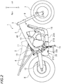
- FIG. 1 and FIG. 2 show a left side view and a right side view, respectively, showing a main part of the motorcycle 1.
- front, rear, left, right, up and down refer to these directions as seen from a virtual rider seated on a seat 2 while the motorcycle 1 is standing upright on a horizontal surface with no rider and no load thereon, unless specified otherwise.
- front/forward refers not only to the direction that extends in the front direction along the vehicle center line CL (see FIG. 4 ), as the vehicle is seen from above or as the vehicle is seen from below, but also to directions that are inclined left/right from that direction by an angle that is less than or equal to 45 degrees.
- the term “rear/rearward” refers not only to the direction that extends rearward along the vehicle center line CL, as the vehicle is seen from above or as the vehicle is seen from below, but also to directions that are inclined left/right from that direction by an angle of 45 degrees or less.
- the term “left/leftward” refers not only to the direction that extends leftward vertical to the vehicle center line CL, as the vehicle is seen from above or as the vehicle is seen from below, but also to directions that are inclined frontward/rearward from that direction by an angle of 45 degrees or less.
- right/rightward refers not only to the direction that extends rightward vertical to the vehicle center line CL, as the vehicle is seen from above or as the vehicle is seen from below, but also to directions that are inclined frontward/rearward from that direction by an angle of 45 degrees or less.
- up/upward refers not only to the vertically upward direction, as the vehicle is seen from sideways, but also to directions that are inclined frontward/rearward from that direction by an angle of 45 degrees or less.
- down/downward refers not only to the vertically downward direction, as the vehicle is seen from sideways, but also to directions that are inclined frontward/rearward from that direction by an angle of 45 degrees or less.
- the motorcycle 1 includes a body frame 5, an engine 10 supported on the body frame 5, a front wheel 7 arranged forward of the engine 10, a rear wheel 8 arranged rearward of the engine 10, and a silencer 20.
- the body frame 5 includes a head pipe 3, left and right main frames 4L and 4R extending rearward from the head pipe 3, and left and right seat frames 6 extending rearward form intermediate portions of the left and right main frames 4L and 4R.
- a steering shaft (not shown) is rotatably supported on the head pipe 3.
- a handle bar (not shown) is secured on the steering shaft.
- a front fork 9 is attached to the steering shaft.
- the front wheel 7 is rotatably supported on a lower end portion of the front fork 9.
- the engine 10 is attached to the main frames 4L and 4R. At least a portion of the seat 2 is supported on the seat frame 6.
- a rear arm 12 is supported on the main frames 4L and 4R so that the rear arm 12 can pivot.
- a front end portion of the rear arm 12 is linked to the main frames 4L and 4R via a pivot shaft 11.
- the rear wheel 8 is rotatably supported on a rear end portion of the rear arm 12.
- a rear cushion unit 13 is provided between the main frames 4L and 4R and the rear arm 12.
- a main stand 15 is attached to a lower portion of the main frames 4L and 4R.
- the engine 10 is an internal combustion engine.
- the engine 10 is a 4-cycle internal combustion engine.
- the engine 10 includes a crank case 10A, a cylinder body 10B connected to the crank case 10A, and a cylinder head 10C connected to the cylinder body 10B.
- An exhaust pipe 16 is connected to the cylinder head 10C.
- the exhaust pipe 16 includes a first portion 16A extending downward from the cylinder head 10C, and a second portion 16B extending rearward from the first portion 16A.
- the first portion 16A is arranged forward of the crank case 10A. At least a portion of the second portion 16B is arranged below the crank case 10A.
- the silencer 20 is connected to the exhaust pipe 16.
- the silencer 20 is connected to a rear end portion of the second portion 16B of the exhaust pipe 16. At least a portion of the silencer 20 is arranged rearward of the engine 10 and forward of the rear wheel 8. A portion of the silencer 20 is arranged below the engine 10. At least a portion of the silencer 20 is arranged on the vehicle center line CL, as the vehicle is seen from below, as shown in FIG. 4 .
- the vehicle center line is a line that connects together the center of the front wheel 7 in the vehicle width direction and the center of the rear wheel 8 in the vehicle width direction, as the vehicle is seen from above or as the vehicle is seen from below, when the motorcycle 1 is unsteered (in other words, when the motorcycle 1 is running straight).
- the silencer 20 of the present embodiment is capable of sufficiently reducing the environmental noise from the exhaust despite its small size. Therefore, it can be installed in a relatively small space.
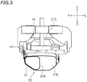
- FIG. 5 is a front view of the silencer 20, etc.
- FIG. 6 is a back view of the silencer 20, etc.
- FIG. 7 is a right side view of the silencer 20.
- FIG. 8 is a horizontal cross-sectional view showing an internal configuration of the silencer 20, and
- FIG. 9 is a vertical cross-sectional view showing an internal configuration of the silencer.
- the silencer 20 includes a case 21, a partition wall 22 arranged inside the case 21, a first pipe 31, a second pipe 32, a third pipe 33, a fourth pipe 34, and a fiber-based silencing material 23.
- the case 21 may be a single component, the case 21 is formed from a plurality of components in the present embodiment.
- the case 21 includes a pipe section 21A, to which the exhaust pipe 16 is connected, a box section 21B, and a box section 21C.
- the box section 21B is located rearward of the pipe section 21A, and the box section 21C is located rearward of the box section 21B.
- the case 21 overlaps the vehicle center line CL as the vehicle is seen from below. At least a portion of the case 21 is located on the vehicle center line CL. While the case 21 is located rightward of the left end of the left main frame 4L and leftward of the right end of the right main frame 4R, the present invention is not limited to this.
- the pipe section 21A is connected to the right-side portion of the box section 21B.
- the center line CL1 of the portion of the pipe section 21A that is connected to the box section 21B is located rightward of the vehicle center line CL as the vehicle is seen from below.
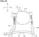
- the main stand 15 includes a left pipe 15L, a right pipe 15R, and a center pipe 15C that connects together the left pipe 15L and the right pipe 15R.
- the case 21 of the silencer 20 is accommodated in the space between the left pipe 15L and the right pipe 15R.
- the case 21 is arranged between the left pipe 15L and the right pipe 15R as the vehicle is seen from the back.
- the case 21 is arranged rightward of the right end of the left pipe 15L and leftward of the left end of the right pipe 15R. Therefore, the case 21 will not interfere with the main stand 15 when the main stand 15 pivots.
- an upper wall 21Bt of the box section 21B is inclined upward from the horizontal line while extending toward the rear side, as the vehicle is seen from sideways.
- the size of the box section 21B in the up-down direction gradually increases toward the rear side.
- An upper wall 21Ct of the box section 21C is formed so as to extend downward, then upward and then downward while extending toward the rear side, as the vehicle is seen from sideways.
- the size of the box section 21C in the up-down direction once decreases, then increases and then decreases again toward the rear side.
- the upper wall 21Ct of the box section 21C has a depression 21Cd that is depressed downward as the vehicle is seen from sideways. As shown in FIG.
- a first chamber 41 is formed inside the box section 21B, and a second chamber 42 is formed inside the box section 21C.
- the average size of the second chamber 42 in the up-down direction is greater than the average size of the first chamber 41 in the up-down direction. Note that the average size of a chamber in the up-down direction can be obtained by dividing the volume of the chamber by the area of the chamber as seen from below.
- a portion of a link mechanism 19 that is linked to the rear cushion unit 13 is arranged above the depression 21Cd of the case 21. With the depression 21Cd, a portion of the link mechanism 19 can be arranged close to the case 21. A portion of the silencer 20 can be arranged in the narrow space between the engine 10 and the rear wheel 8 without interferring with the link mechanism 19.
- the partition wall 22 partitions the inside of the case 21 into the first chamber 41 and the second chamber 42.
- the volume of the second chamber 42 is greater than the volume of the first chamber 41.
- the second chamber 42 is located rearward of the first chamber 41.
- the first chamber 41 is formed forward of the partition wall 22, and the second chamber 42 is formed rearward of the partition wall 22.
- only the first chamber 41 and the second chamber 42 are provided inside the case 21. That is, only two chambers are provided inside the case 21. While the partition wall 22 is herein separate from the case 21, they may be integral together.
- the first pipe 31 is a cylinder with a plurality of holes 31d formed therein.
- the first pipe 31 may be a cylindrical punched metal.
- the first pipe 31 is a straight pipe. Note however that the first pipe 31 may be bent.
- the first pipe 31 includes a first inlet 31a, a first peripheral wall 31b and a first outlet 31c.
- the first inlet 31a has an opening facing frontward.
- An exhaust gas from the exhaust pipe 16 flows into the first inlet 31a.
- the first outlet 31c has an opening facing rearward.
- the first outlet 31c is opened into the second chamber 42.
- the first peripheral wall 31b is arranged in the first chamber 41.
- the holes 31d are formed in the first peripheral wall 31b.
- the holes 31d connect together the inside and the outside of the first peripheral wall 31b.
- the first pipe 31 is arranged so as to bridge between the pipe section 21A and the box section 21B.
- a portion of the first pipe 31 is arranged inside the pipe section 21A, and another portion of the first pipe 31 is arranged inside the box section 21B.
- the first pipe 31 may be arranged only inside the box section 21B.
- a portion of the first pipe 31 may be arranged inside the box section 21C.
- a portion of the first pipe 31 may be arranged inside the second chamber 42.
- pipe refers to a member that has an inlet and an outlet and is capable of guiding a fluid from the inlet toward the outlet.
- the "pipe” does not need to be formed in a tubular shape.
- the cross-sectional shape of the "pipe” is not limited to a circular shape, but may be an elliptical shape, a rectangular shape, or the like.
- the inner diameter of the "pipe” (the hydraulically equivalent diameter when the cross-sectional shape is other than a circular shape) does not need to be constant.
- One or both ends of the "pipe” may be closed.
- the "pipe” may be a cylinder both ends of which are closed, with a hole to be the inlet and a hole to be the outlet.
- the second pipe 32 includes a tube 32A with a plurality of holes 32d formed therein, and a plate 32B with a plurality of holes 32d formed therein.
- the tube 32A is a pentagonal tube
- the plate 32B is a pentagonal plate.
- the cross-sectional shape of the tube 32A and the plate 32B may be for example a circular shape, an elliptical shape, a polygonal shape other than a pentagonal shape, or any other shape.
- the upper portion of the tube 32A has a tapered shape and is inclined upward while extending rearward. The inner diameter of the tube 32A gradually increases rearward.
- the inner diameter of the tube 32A refers to a hydraulically equivalent diameter of the tube 32A.
- the plate 32B closes the front end of the tube 32A. As shown in FIG. 8 , the tube 32A extends straight in the present embodiment. Note however that the tube 32A may be bent.
- the second pipe 32 includes a second inlet 32a and a second peripheral wall 32b.
- the second inlet 32a has an opening facing rearward.
- the second inlet 32a is opened into the second chamber 42.
- the second peripheral wall 32b is arranged inside the first chamber 41.
- the holes 32d are formed in the second peripheral wall 32b. The holes 32d connect together the inside and the outside of the second peripheral wall 32b.
- the holes 32d of the plate 32B also connect together the inside and the outside of the second peripheral wall 32b.
- the plate 32B may be absent.
- the front end of the tube 32A may have an opening facing frontward.
- the holes 32d of the plate 32B may be absent.
- the front end of the tube 32A may be tightly closed.
- a plate with a hole formed therein may be provided on the rear end of the tube 32A. In such a case, the hole serves as the second inlet of the second pipe 32.
- the third pipe 33 is a curved cylinder. Note however that the third pipe 33 may be a straight cylinder.
- the third pipe 33 is bent inside the second chamber 42. Note that as opposed to the first pipe 31 and the second pipe 32, no hole is formed in the cylinder of the third pipe 33.
- the third pipe 33 includes a third inlet 33a arranged inside the second pipe 32, a third peripheral wall 33b arranged inside the second pipe 32 and inside the second chamber 42, and a third outlet 33c that is opened toward the outside of the case 21.
- the third inlet 33a has an opening facing frontward.
- the third pipe 33 is connected to a bottom wall 21a of the case 21.
- the third pipe 33 is connected to the bottom wall 21a of the box section 21C.
- the fourth pipe 34 is a curved cylinder. Note however that the fourth pipe 34 may be a straight cylinder.
- the fourth pipe 34 is bent inside the second chamber 42. As with the third pipe 33, no hole is formed in the cylinder of the fourth pipe 34.
- the fourth pipe 34 includes a fourth inlet 34a arranged inside the second pipe 32, a fourth peripheral wall 34b arranged inside the second pipe 32 and inside the second chamber 42, and a fourth outlet 34c that is opened toward the outside of the case 21.
- the fourth inlet 34a has an opening facing frontward.
- the fourth pipe 34 is connected to the bottom wall 21a of the case 21.
- the fourth pipe 34 is connected to the bottom wall 21a of the box section 21C.
- the cross-sectional shape of the third pipe 33 and the fourth pipe 34 does not need to be a circular shape, but may be an elliptical shape, a polygonal shape, or the like. There is no particular limitation on the shape of the third pipe 33 and the fourth pipe 34.
- the second pipe 32 is arranged leftward of the first pipe 31.
- the third inlet 33a of the third pipe 33 and the fourth inlet 34a of the fourth pipe 34 are both arranged leftward of the first pipe 31.
- the silencer 20 may be formed in a left-right-inverted shape. In such a case, the second pipe 32 is arranged rightward of the first pipe 31, and the third inlet 33a of the third pipe 33 and the fourth inlet 34a of the fourth pipe 34 are arranged rightward of the first pipe 31.
- the length of the third pipe 33 and the length of the fourth pipe 34 are from each other.
- the lengths of the third pipe 33 and the fourth pipe 34 refer to their lengths along the center lines of the third pipe 33 and the fourth pipe 34.
- the third pipe 33 and the fourth pipe 34 are curved. Therefore, the length of the third pipe 33 is greater than the size of the third pipe 33 in the front-rear direction, and the length of the fourth pipe 34 is greater than the size of the fourth pipe 34 in the front-rear direction.
- the length of the fourth pipe 34 is greater than the length of the third pipe 33.
- the length of the third pipe 33 may be greater than the length of the fourth pipe 34.
- the length of the third pipe 33 may be equal to the length of the fourth pipe 34.
- the length of the first pipe 31 is greater than the length of the second pipe 32.
- the length of the first pipe 31 may be equal to the length of the second pipe 32, or the length of the second pipe 32 may be greater than the length of the first pipe 31.
- the length of the third pipe 33 and the length of the fourth pipe 34 are greater than the length of the first pipe 31.
- the length of the third pipe 33 and/or the fourth pipe 34 may be equal to the length of the first pipe 31, or the length of the first pipe 31 may be greater than the length of the third pipe 33 and/or the fourth pipe 34.
- the length of the third pipe 33 and the length of the fourth pipe 34 may be greater than the length of the second pipe 32.
- the length of the second pipe 32 may be equal to the length of the third pipe 33 and/or the fourth pipe 34, or greater than the length of the third pipe 33 and/or the fourth pipe 34.
- the inner diameter of the third pipe 33 may be equal to or different from the inner diameter of the fourth pipe 34.
- the inner diameter of the third pipe 33 may be greater or less than the inner diameter of the fourth pipe 34.
- the inner diameter of the third pipe 33 and the inner diameter of the fourth pipe 34 are equal to each other.
- the inner diameter of the third pipe 33 and the inner diameter of the fourth pipe 34 are each less than the inner diameter of the exhaust pipe 16. Note however that the present invention is not limited to this.
- the inner diameter of the shorter one (i.e., one that has a lower silencing capacity) of the third pipe 33 and the fourth pipe 34 may be less than the inner diameter of the longer one. Then, it is possible to adjust the distribution of the exhaust sound energy. Note that when the inner diameter of a pipe is not constant, it is assumed that the inner diameter of the pipe means the average inner diameter.
- the inner diameter of the second pipe 32 is greater than the inner diameter of the first pipe 31.
- the inner diameter of the first pipe 31 is greater than each of the inner diameter of the third pipe 33 and the inner diameter of the fourth pipe 34.
- the inner diameter of the first pipe 31 is greater than the sum of the inner diameter of the third pipe 33 and the inner diameter of the fourth pipe 34.
- the inner diameter of the first pipe 31 may be equal to the inner diameter of the second pipe 32, or greater than the inner diameter of the second pipe 32.
- the inner diameter of the first pipe 31 may be equal to the inner diameter of the third pipe 33 and/or the fourth pipe 34, or may be less than the inner diameter of the third pipe 33 and/or the fourth pipe 34.
- the openings of the third outlet 33c and the fourth outlet 34c are facing downward.
- the center line CL2 of FIG. 8 is a line that passes through the center of the case 21 in the vehicle width direction.
- the third outlet 33c is located rightward of the middle of the case 21 in the vehicle width direction.
- the fourth outlet 34c is located leftward of the middle of the case 21 in the vehicle width direction. Note however that the third outlet 33c may be located leftward of the middle of the case 21 in the vehicle width direction.
- the fourth outlet 34c may be located rightward of the middle of the case 21 in the vehicle width direction.
- the third outlet 33c and the fourth outlet 34c may both be located leftward or rightward of the middle of the case 21 in the vehicle width direction. There is no particular limitation on the positions of the third outlet 33c and the fourth outlet 34c.
- the third outlet 33c is located rightward of the vehicle center line CL and the fourth outlet 34c is located leftward of the vehicle center line CL, as the vehicle is seen from below. Note however that the third outlet 33c may be located leftward of the vehicle center line CL. The fourth outlet 34c may be located rightward of the vehicle center line CL. The third outlet 33c and the fourth outlet 34c may both be located leftward or rightward of the vehicle center line CL.
- the center line 33k of the third outlet 33c is inclined rightward with respect to the vehicle center line CL while extending rearward.
- the center line 34k of the fourth outlet 34c is inclined leftward with respect to the vehicle center line CL while extending rearward. Note however that as the vehicle is seen from below, the center line 33k of the third outlet 33c may be inclined leftward with respect to the vehicle center line CL while extending rearward. As the vehicle is seen from below, the center line 34k of the fourth outlet 34c may be inclined rightward with respect to the vehicle center line CL while extending rearward.
- the center line 33k of the third outlet 33c and/or the center line 34k of the fourth outlet 34c may be parallel to the vehicle center line CL.
- the third pipe 33 and the fourth pipe 34 are not protruding out of the case 21.
- the third outlet 33c of the third pipe 33 and the fourth outlet 34c of the fourth pipe 34 are arranged inside the outline of the case 21, as the vehicle is seen from sideways and as the vehicle is seen from below. Note however that the third pipe 33 and the fourth pipe 34 may be formed so as to protrude out of the case 21.
- the fiber-based silencing material 23 is provided inside the first chamber 41 and outside the first pipe 31 and the second pipe 32.
- the fiber-based silencing material 23 is made of a glass wool. Note however that the fiber-based silencing material 23 may be any material other than a glass wool. In the following description, the fiber-based silencing material 23 will be referred to simply as the silencing material 23.
- a portion of the silencing material 23 is arranged around the first peripheral wall 31b of the first pipe 31.
- the silencing material 23 communicates with the inside of the first pipe 31 through the holes 31d of the first peripheral wall 31b.
- Another portion of the silencing material 23 is arranged around the second peripheral wall 32b of the second pipe 32.
- Another portion of the silencing material 23 is arranged forward of the plate 32B of the second pipe 32.
- the silencing material 23 communicates with the inside of the second pipe 32 through the holes 32d of the second pipe 32.
- the silencing material 23 communicates with both the inside of the first pipe 31 and the inside of the second pipe 32 through the holes 31d and the holes 32d.
- the exhaust gas flows into the silencer 20 through the exhaust pipe 16 and expands. As indicated by arrow F1 in FIG. 8 , in the first chamber 41, the exhaust gas flows through the inside of the first pipe 31. Since the inside of the first pipe 31 communicates with the silencing material 23 through the holes 31d, the noise is reduced while the exhaust gas passes through the first pipe 31. Particularly, the silencing material 23 effectively reduces the high-frequency component of the noise.
- the exhaust gas After passing through the first pipe 31, the exhaust gas flows into the second chamber 42. Then, the exhaust gas expands. This expansion reduces the noise. Particularly, it effectively reduces the low-frequency component of the noise. As indicated by arrow F2, the exhaust gas flows into the second pipe 32 from the second chamber 42.
- the silencing material 23 effectively reduces the high-frequency component of the noise.
- a portion of the exhaust gas in the second pipe 32 flows into the third pipe 33.
- the exhaust gas, having flown through the third pipe 33 is emitted to the outside through the third outlet 33c.
- another portion of the exhaust gas in the second pipe 32 flows into the fourth pipe 34.
- the exhaust gas, having flown through the fourth pipe 34 is emitted to the outside through the fourth outlet 34c.
- the inside of the case 21 of the silencer 20 is partitioned by the partition wall 22 into the first chamber 41 and the second chamber 42.
- the inside of the case 21 is partitioned into three chambers, it is possible to increase the volume of the second chamber 42 without increasing the size of the case 21.
- the fiber-based silencing material 23 is arranged inside the first chamber 41 and outside the first pipe 31 and the second pipe 32. Therefore, while the exhaust gas flows through the first pipe 31 and the second pipe 32, it is possible to effectively reduce the high-frequency component of the environmental noise from the exhaust.
- the silencing material 23 communicates with the inside of the first pipe 31 through the holes 31d, and communicates with the inside of the second pipe 32 through the holes 32d.
- the silencing material 23 around the first pipe 31 and the silencing material 23 around the second pipe 32 are not partitioned from each other. It is possible, using a single silencing material 23, to silence the exhaust gas flowing through the first pipe 31 and silence the exhaust gas flowing through the second pipe 32. Since the silencing material 23 can be shared as described above, it is possible to reduce the installation space for the silencing material 23. Thus, it is possible to reduce the size of the silencer 20.
- the motorcycle 1 includes two pipes for emitting the exhaust gas out of the case 21, i.e., the third pipe 33 and the fourth pipe 34. As compared with a case where the exhaust gas is emitted by using one pipe, the sound to be emitted out of the case 21 can be dispersed.
- the third pipe 33 and the fourth pipe 34 are connected to the bottom wall 21a of the case 21. Since the sound from the third pipe 33 and the fourth pipe 34 is discharged downward, it is possible to effectively reduce the environmental noise from the exhaust. Moreover, it is possible to prevent a hot exhaust gas from blowing onto the rear wheel 8. Since the exhaust gas is less likely to be blowing onto the rear wheel 8, the silencer 20 can be arranged close to the rear wheel 8 (see FIG. 3 ). It is possible to arrange the silencer 20 in the narrow space between the engine 10 and the rear wheel 8.
- the third outlet 33c of the third pipe 33 is located rightward of the middle of the case 21 in the vehicle width direction.
- the fourth outlet 34c of the fourth pipe 34 is located leftward of the middle of the case 21 in the vehicle width direction. Therefore, the sound discharged from the third pipe 33 and the fourth pipe 34 is distributed left and right. Therefore, it is possible to effectively reduce the environmental noise from the exhaust.
- the third outlet 33c of the third pipe 33 is located rightward of the vehicle center line CL and the fourth outlet 34c of the fourth pipe 34 is located leftward of the vehicle center line CL, as the vehicle is seen from below. Therefore, the sound discharged from the third pipe 33 and the fourth pipe 34 is distributed left and right. Therefore, it is possible to effectively reduce the environmental noise from the exhaust.
- the center line 33k of the third outlet 33c is inclined rightward with respect to the vehicle center line CL while extending rearward, as the vehicle is seen from below.
- the center line 34k of the fourth outlet 34c is inclined leftward with respect to the vehicle center line CL while extending rearward, as the vehicle is seen from below. Therefore, the sound discharged from the third pipe 33 and the fourth pipe 34 is distributed left and right. Therefore, it is possible to effectively reduce the environmental noise from the exhaust.
- the length of the third pipe 33 and the length of the fourth pipe 34 are different from each other, as shown in FIG. 8 .
- the frequency of sound that is discharged from the third pipe 33 and the frequency of sound that is discharged from the fourth pipe 34 can be different from each other.
- the third outlet 33c and the fourth outlet 34c are arranged inside the outline of the case 21, as the vehicle is seen from sideways and as the vehicle is seen from below. Since the third pipe 33 and the fourth pipe 34 are not protruding out of the case 21, they are unlikely to interfere with vehicle components other than the silencer 20. Therefore, there is little constraint on designing the vehicle. It is possible to relatively freely install vehicle components without being interfered with the third pipe 33 and the fourth pipe 34.
- the third pipe 33 and the fourth pipe 34 extend from the first chamber 41 to the outside of the case 21 via the second chamber 42. Since the second chamber 42 is relatively large, it is easy to reserve a space for the third pipe 33 and the fourth pipe 34 to be bent midway. In the present embodiment, the third pipe 33 and the fourth pipe 34 are bent inside the second chamber 42. Since it is possible to ensure sufficient lengths of the third pipe 33 and the fourth pipe 34, it is possible to effectively reduce the environmental noise from the exhaust. By bending the third pipe 33 and the fourth pipe 34 midway as appropriate, it is possible to adjust the frequency component of the environmental noise from the exhaust discharged from the third pipe 33 and the fourth pipe 34.
- the inner diameter of the third pipe 33 and the inner diameter of the fourth pipe 34 are each smaller than the inner diameter of the exhaust pipe 16. It is possible to effectively reduce the environmental noise from the exhaust through the third pipe 33 and the fourth pipe 34.
- the third inlet 33a of the third pipe 33 and the fourth inlet 34a of the fourth pipe 34 are arranged leftward of the first pipe 31.
- the first pipe 31 is arranged in the case 21 lopsided to the right side.
- FIG. 8 it is possible to provide a space SP in front of the left portion of the case 21.
- Other vehicle components can be arranged in this space SP, and the silencer 20 can be arranged in a compact manner.
- an oil pan 10Aa which is a part of the crank case 10A of the engine 10, is arranged in the space SP.
- the volume of the second chamber 42 does not need to be greater than the volume of the first chamber 41, but is greater than the volume of the first chamber 41 in the present embodiment. According to the present embodiment, by expanding the exhaust gas through the second chamber 42 having a large volume, it is possible to effectively reduce the low-frequency component of the environmental noise from the exhaust.
- the average size of the second chamber 42 in the up-down direction is greater than the average size of the first chamber 41 in the up-down direction. Therefore, it is possible to ensure a sufficient volume of the second chamber 42 without increasing the size of the case 21 in the front-rear direction. It is possible to ensure a sufficient volume of the second chamber 42 in the narrow space between the engine 10 and the rear wheel 8.
- the silencing material 23 is a glass wool. While a hot exhaust gas flows into the first chamber 41, a glass wool is a material that has a good heat resistance. By using a glass wool as the silencing material 23, it is possible to increase the heat resistance of the silencing material 23.
- the silencer 20 may be provided with a left-right-inverted structure.
- the second pipe 32 is arranged rightward of the first pipe 31.
- the inlet 33a of the third pipe 33 and the inlet 34a of the fourth pipe 34 are arranged rightward of the first pipe 31.
- FIG. 11 Another embodiment shown in FIG. 11 is obtained by changing the shape of the case 21 of the silencer 20, the length of the first pipe 31, etc. Like members and sections to those of the embodiment described above will be denoted by like reference numerals and will not be described below.
- another pipe 39 whose inner diameter gradually increases while extending frontward is connected to the front end portion of the first pipe 31.
- the case 21 may include the pipe section 21A to which the exhaust pipe 16 is connected, the pipe section 21A may be omitted by connecting the exhaust pipe 16 to the box section 21B. Otherwise, the configuration is similar to the embodiment described above.
- FIG. 12 Another embodiment shown in FIG. 12 is obtained by arranging second pipes 32 on both sides, left and right, of the first pipe 31.
- the third inlet 33a of the third pipe 33 is arranged inside a second pipe 32 that is arranged rightward of the first pipe 31.
- the fourth inlet 34a of the fourth pipe 34 is arranged inside an additional second pipe 32 that is arranged leftward of the first pipe 31.
- the silencing material 23 is arranged inside the first chamber 41 and outside the first pipe 31, the second pipe 32 and the additional second pipe 32. Otherwise, the configuration is similar to the embodiment described above, and the description is omitted. Note that in FIG. 12 , like members and sections to those of the embodiment described above are denoted by like reference numerals.
- the exhaust gas flows through the inside of the first pipe 31, as indicated by arrow F1. Since the inside of the first pipe 31 communicates with the silencing material 23 through the holes 31d, the noise is reduced while the exhaust gas passes through the first pipe 31. Particularly, the silencing material 23 effectively reduces the high-frequency component of the noise.
- the exhaust gas After passing through the first pipe 31, the exhaust gas flows into the second chamber 42. Then, the exhaust gas expands. This expansion reduces the noise. Particularly, it effectively reduces the low-frequency component of the noise. As indicated by arrow F2, the exhaust gas flows into the second pipes 32 from the second chamber 42.
- each second pipe 32 communicates with the silencing material 23 through the holes 32d, the noise is reduced while the exhaust gas flows through the inside of each second pipe 32.
- the silencing material 23 effectively reduces the high-frequency component of the noise.
- the exhaust gas in the second pipe 32 flows into the third pipe 33.
- the exhaust gas, having flown through the third pipe 33 is emitted to the outside through the third outlet 33c.
- the exhaust gas in the additional second pipe 32 flows into the fourth pipe 34.
- the exhaust gas, having flown through the fourth pipe 34 is emitted to the outside through the fourth outlet 34c.
- a straddled vehicle refers to a vehicle that is straddled by a passenger. While a motorcycle is an example straddled vehicle, a straddled vehicle is not limited to a motorcycle. A straddled vehicle may be an auto tricycle, an ATV (All Terrain Vehicle), or the like.
- the engine 10 is not limited to a 4-cycle internal combustion engine.
- the engine 10 may be a 2-cycle internal combustion engine, for example.
- the third pipe 33 and the fourth pipe 34 do not need to be connected to the bottom wall 21a of the case 21.
- the third outlet 33c and the fourth outlet 34c do not need to be opened in the downward direction.
- the third pipe 33 and/or the fourth pipe 34 may be connected to the side wall of the case 21, for example.
- the third outlet 33c and/or the fourth outlet 34c may be opened leftward or rightward, for example.
Landscapes
- Engineering & Computer Science (AREA)
- Chemical & Material Sciences (AREA)
- Combustion & Propulsion (AREA)
- Mechanical Engineering (AREA)
- General Engineering & Computer Science (AREA)
- Exhaust Silencers (AREA)
Abstract
Description
- The present invention relates to a straddled vehicle.
- Conventional straddled vehicles including a silencer for reducing the environmental noise from the exhaust are know in the art. Japanese Laid-Open Patent Publication No.
2009-248824 - The silencer disclosed in Japanese Laid-Open Patent Publication No.
2009-248824 - With a straddled vehicle, the distance between the engine and the rear wheel tends to be relatively short, and the space between the engine and the rear wheel is small. The size of the silencer being large imposes tight constraints on designing the vehicle. However, simply reducing the size of the silencer will reduce the volumes of the expansion chambers, and it is then difficult to sufficiently reduce the environmental noise from the exhaust.
- It is an object of the present invention, which has been made in order to solve such a problem, to provide a straddled vehicle including a silencer arranged between the engine and the rear wheel, with which it is possible to reduce the environmental noise from the exhaust and reduce the size of the silencer.
- The present inventor focused on the fact that the environmental noise from the exhaust can be generally classified into a low-frequency component and a high-frequency component, for each of which there is an effective silencing mechanism. First, the present inventor considered reducing the number of expansion chambers in the case, and instead providing expansion chambers of greater capacities than those of the conventional techniques. Then, it is possible to increase the degree by which the exhaust gas expands at a time even though the number of times the exhaust gas expands is reduced. Thus, it is possible to effectively reduce the low-frequency component. Next, the present inventor considered arranging a fiber-based sound-absorbing material such as a glass wool in one expansion chamber. Then, it is possible to effectively reduce the high-frequency component. The present inventor thus found that it is possible to reduce the environmental noise from the exhaust without increasing the size of the silencer by using suitable silencing mechanisms for the low-frequency component and for the high-frequency component. The present invention is based on this finding.
- Above object is achieved by a straddled vehicle according to the configurations of claim 1 or 2.
- A straddled vehicle disclosed herein includes: an engine; a rear wheel arranged rearward of the engine; an exhaust pipe connected to the engine; and a silencer connected to the exhaust pipe, at least a portion of which is arranged rearward of the engine and forward of the rear wheel. The silencer includes a case, a partition wall, a first pipe, a second pipe, a fiber-based silencing material, a third pipe, and a fourth pipe. At least a portion of the case is arranged on a vehicle center line as the vehicle is seen from below. The partition wall is arranged inside the case and partitions the inside of the case into a first chamber and a second chamber. The first pipe has a first inlet through which an exhaust gas from the exhaust pipe flows into the first pipe, a first peripheral wall that is arranged in the first chamber and has a plurality of through holes, and a first outlet that is opened into the second chamber. The second pipe has a second inlet that is opened into the second chamber, and a second peripheral wall that is arranged in the first chamber and has a plurality of through holes. The fiber-based silencing material is arranged inside the first chamber and outside the first pipe and the second pipe. The third pipe has a third inlet that is arranged inside the second pipe, a third peripheral wall that is arranged inside the second pipe and inside the second chamber, and a third outlet that is opened toward an outside of the case. The fourth pipe has a fourth inlet that is arranged inside the second pipe, a fourth peripheral wall that is arranged inside the second pipe and inside the second chamber, and a fourth outlet that is opened toward the outside of the case.
- With the straddled vehicle described above, the inside of the case is partitioned into two chambers. As compared with conventional techniques where the inside of the case is partitioned into three chambers, it is possible to increase the volume of the second chamber without increasing the size of the case. By expanding the exhaust gas through the second chamber having a large volume, it is possible to effectively reduce the low-frequency component of the environmental noise from the exhaust. With the straddled vehicle described above, through holes are formed in the first peripheral wall of the first pipe and the second peripheral wall of the second pipe, and the fiber-based silencing material is arranged inside the first chamber and outside the first pipe and the second pipe. Therefore, while the exhaust gas flows through the first pipe and the second pipe, it is possible to effectively reduce the high-frequency component of the environmental noise from the exhaust. It is possible, using a single fiber-based silencing material, to silence the exhaust gas flowing through the first pipe and silence the exhaust gas flowing through the second pipe. Since the fiber-based silencing material can be shared as described above, it is possible to reduce the installation space for the fiber-based silencing material. Thus, it is possible to reduce the size of the silencer. The straddled vehicle described above includes two pipes (i.e., the third pipe and the fourth pipe) for emitting the exhaust gas out of the case. Therefore, as compared with a case where the exhaust gas is emitted out of the case by using one pipe, the sound to be emitted out of the case can be dispersed. With the straddled vehicle described above, these advantageous effects are synergistically combined together, and it is possible to reduce the environmental noise from the exhaust and reduce the size of the silencer.
- Another straddled vehicle disclosed herein includes: an engine; a rear wheel arranged rearward of the engine; an exhaust pipe connected to the engine; and a silencer connected to the exhaust pipe, at least a portion of which is arranged rearward of the engine and forward of the rear wheel. The silencer includes a case, a partition wall, a first pipe, a second pipe, an additional second pipe, a fiber-based silencing material, a third pipe, and a fourth pipe. At least a portion of the case is arranged on a vehicle center line as the vehicle is seen from below. The partition wall is arranged inside the case and partitions the inside of the case into a first chamber and a second chamber. The first pipe has a first inlet through which an exhaust gas from the exhaust pipe flows into the first pipe, a first peripheral wall that is arranged in the first chamber and has a plurality of through holes, and a first outlet that is opened into the second chamber. The second pipe has a second inlet that is opened into the second chamber, and a second peripheral wall that is arranged in the first chamber and has a plurality of through holes. The additional second pipe has an additional second inlet that is opened into the second chamber, and an additional second peripheral wall that is arranged in the first chamber and has a plurality of through holes. The fiber-based silencing material is arranged inside the first chamber and outside the first pipe, the second pipe and the additional second pipe. The third pipe has a third inlet that is arranged inside the second pipe, a third peripheral wall that is arranged inside the second pipe and inside the second chamber, and a third outlet that is opened toward an outside of the case. The fourth pipe has a fourth inlet that is arranged inside the additional second pipe, a fourth peripheral wall that is arranged inside the additional second pipe and inside the second chamber, and a fourth outlet that is opened toward the outside of the case.
- Also with the straddled vehicle described above, the inside of the case is partitioned into two chambers, and it is therefore possible to increase the volume of the second chamber without increasing the size of the case. By expanding the exhaust gas through the second chamber having a large volume, it is possible to effectively reduce the low-frequency component of the environmental noise from the exhaust. With the straddled vehicle described above, through holes are formed in the first peripheral wall of the first pipe, the second peripheral wall of the second pipe and the additional second peripheral wall of the additional second pipe, and the fiber-based silencing material is arranged inside the first chamber and outside the first pipe, the second pipe and the additional second pipe. Therefore, while the exhaust gas flows through the first pipe, the second pipe and the additional second pipe, it is possible to effectively reduce the high-frequency component of the environmental noise from the exhaust. It is possible, using a single fiber-based silencing material, to silence the exhaust gas flowing through the first pipe, the second pipe and the additional second pipe. Since the fiber-based silencing material can be shared as described above, it is possible to reduce the installation space for the fiber-based silencing material. Thus, it is possible to reduce the size of the silencer. The straddled vehicle described above includes two pipes (i.e., the third pipe and the fourth pipe) for emitting the exhaust gas out of the case. Therefore, as compared with a case where the exhaust gas is emitted by using one pipe, the sound to be emitted out of the case can be dispersed. With the straddled vehicle described above, these advantageous effects are synergistically combined together, and it is possible to reduce the environmental noise from the exhaust and reduce the size of the silencer.
- In one preferred aspect, the case has a bottom wall. The third pipe and the fourth pipe are connected to the bottom wall.
- In this aspect, since the sound from the third pipe and the fourth pipe is discharged downward, it is possible to effectively reduce the environmental noise from the exhaust. Moreover, it is possible to prevent a hot exhaust gas from blowing onto the rear wheel.
- In one preferred aspect, one of the third outlet and the fourth outlet is located leftward of a middle of the case in a vehicle width direction. The other one of the third outlet and the fourth outlet is located rightward of the middle of the case in the vehicle width direction.
- In this aspect, the sound discharged from the third pipe and the fourth pipe is distributed left and right. Therefore, it is possible to effectively reduce the environmental noise from the exhaust.
- In one preferred aspect, as the vehicle is seen from below, one of the third outlet and the fourth outlet is located leftward of the vehicle center line. The other one of the third outlet and the fourth outlet is located rightward of the vehicle center line.
- In this aspect, the sound discharged from the third pipe and the fourth pipe is distributed left and right. Therefore, it is possible to effectively reduce the environmental noise from the exhaust.
- In one preferred aspect, as the vehicle is seen from below, one of a center line of the third outlet and a center line of the fourth outlet is inclined leftward with respect to the vehicle center line while extending rearward. The other one of the center line of the third outlet and the center line of the fourth outlet is inclined rightward with respect to the vehicle center line while extending rearward.
- In this aspect, the sound discharged from the third pipe and the fourth pipe is distributed left and right. Therefore, it is possible to effectively reduce the environmental noise from the exhaust.
- In one preferred aspect, a length of the third pipe and a length of the fourth pipe are different from each other.
- In this aspect, it is possible to adjust the frequency of the sound that is discharged from the third pipe and the frequency of the sound that is discharged from the fourth pipe. Therefore, it is possible to effectively reduce the environmental noise from the exhaust.
- In one preferred aspect, the third outlet and the fourth outlet are arranged inside an outline of the case, as the vehicle is seen from sideways and as the vehicle is seen from below.
- In this aspect, since the third pipe and the fourth pipe are not protruding out of the case, there is little constraint on designing the vehicle.
- In one preferred aspect, the third pipe and the fourth pipe are bent inside the second chamber.
- The third pipe and the fourth pipe extend from the first chamber to the outside of the case via the second chamber. Since the second chamber is relatively large, it is easy to reserve a space for the third pipe and the fourth pipe to be bent midway. In this aspect, since it is possible to ensure sufficient lengths of the third pipe and the fourth pipe, it is possible to effectively reduce the environmental noise from the exhaust. Moreover, by bending the third pipe and the fourth pipe midway as appropriate, it is possible to adjust the frequency component of the environmental noise from the exhaust discharged from the third pipe and the fourth pipe.
- In one preferred aspect, an inner diameter of the third pipe and an inner diameter of the fourth pipe are each less than an inner diameter of the exhaust pipe.
- In this aspect, it is possible to effectively reduce the environmental noise from the exhaust.
- In one preferred aspect, the third inlet and the fourth inlet are both arranged leftward or rightward of the first pipe.
- In this aspect, the first pipe can be arranged lopsided to the left side or the right side of the case.
- In one preferred aspect, a volume of the second chamber is greater than a volume of the first chamber.
- In this aspect, by expanding the exhaust gas through the second chamber having a large volume, it is possible to effectively reduce the low-frequency component of the environmental noise from the exhaust.
- In one preferred aspect, an average size of the second chamber in an up-down direction is greater than an average size of the first chamber in the up-down direction.
- In this aspect, it is possible to ensure a sufficient volume of the second chamber without increasing the size of the case in the front-rear direction. It is possible to ensure a sufficient volume of the second chamber in the narrow space between the engine and the rear wheel.
- In one preferred aspect of the present invention, the fiber-based silencing material is a glass wool.
- A hot exhaust gas flows into the first chamber. In this aspect, it is possible to increase the heat resistance of the fiber-based silencing material.
- According to the present invention, it is possible to provide a straddled vehicle including a silencer arranged between the engine and the rear wheel, with which it is possible to reduce the environmental noise from the exhaust and reduce the size of the silencer.
-
-
FIG. 1 is a left side view showing a main part of a motorcycle according to an embodiment. -
FIG. 2 is a right side view showing the main part of the motorcycle. -
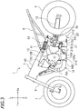
FIG. 3 is a left side view showing a portion of the main part of the motorcycle. -
FIG. 4 is a bottom view showing the silencer, the rear wheel, etc. -
FIG 5 is a front view showing the silencer, etc. -
FIG. 6 is a back view showing the silencer, etc. -
FIG. 7 is a right side view showing the silencer. -
FIG. 8 is a horizontal cross-sectional view showing the silencer. -
FIG. 9 is a right side view of the silencer showing a vertical cross-sectional view of a portion of the silencer. -
FIG. 10 is a back view showing the silencer and the main stand. -
FIG. 11 is a horizontal cross-sectional view showing a silencer according to another embodiment. -
FIG. 12 is a horizontal cross-sectional view showing a silencer according to another embodiment. - Embodiments of the present invention will now be described. As shown in
FIG. 1 andFIG. 2 , a straddled vehicle of the present embodiment is a motorcycle 1. -
FIG. 1 andFIG. 2 show a left side view and a right side view, respectively, showing a main part of the motorcycle 1. - The terms front, rear, left, right, up and down, as used in the description below, refer to these directions as seen from a virtual rider seated on a seat 2 while the motorcycle 1 is standing upright on a horizontal surface with no rider and no load thereon, unless specified otherwise. The designations F, Re, L, R, U and D, as used in the figures, refer to front, rear, left, right, up and down, respectively. The term "front/forward" refers not only to the direction that extends in the front direction along the vehicle center line CL (see
FIG. 4 ), as the vehicle is seen from above or as the vehicle is seen from below, but also to directions that are inclined left/right from that direction by an angle that is less than or equal to 45 degrees. Similarly, the term "rear/rearward" refers not only to the direction that extends rearward along the vehicle center line CL, as the vehicle is seen from above or as the vehicle is seen from below, but also to directions that are inclined left/right from that direction by an angle of 45 degrees or less. The term "left/leftward" refers not only to the direction that extends leftward vertical to the vehicle center line CL, as the vehicle is seen from above or as the vehicle is seen from below, but also to directions that are inclined frontward/rearward from that direction by an angle of 45 degrees or less. The term "right/rightward" refers not only to the direction that extends rightward vertical to the vehicle center line CL, as the vehicle is seen from above or as the vehicle is seen from below, but also to directions that are inclined frontward/rearward from that direction by an angle of 45 degrees or less. The term "up/upward" refers not only to the vertically upward direction, as the vehicle is seen from sideways, but also to directions that are inclined frontward/rearward from that direction by an angle of 45 degrees or less. The term "down/downward" refers not only to the vertically downward direction, as the vehicle is seen from sideways, but also to directions that are inclined frontward/rearward from that direction by an angle of 45 degrees or less. - As shown in
FIG. 1 andFIG. 2 , the motorcycle 1 includes abody frame 5, anengine 10 supported on thebody frame 5, afront wheel 7 arranged forward of theengine 10, arear wheel 8 arranged rearward of theengine 10, and asilencer 20. - The
body frame 5 includes a head pipe 3, left and rightmain frames main frames front fork 9 is attached to the steering shaft. Thefront wheel 7 is rotatably supported on a lower end portion of thefront fork 9. Theengine 10 is attached to themain frames seat frame 6. - A
rear arm 12 is supported on themain frames rear arm 12 can pivot. A front end portion of therear arm 12 is linked to themain frames pivot shaft 11. Therear wheel 8 is rotatably supported on a rear end portion of therear arm 12. Arear cushion unit 13 is provided between themain frames rear arm 12. Amain stand 15 is attached to a lower portion of themain frames - The
engine 10 is an internal combustion engine. Herein, theengine 10 is a 4-cycle internal combustion engine. As shown inFIG. 3 , theengine 10 includes a crankcase 10A, acylinder body 10B connected to the crankcase 10A, and acylinder head 10C connected to thecylinder body 10B. Anexhaust pipe 16 is connected to thecylinder head 10C. Theexhaust pipe 16 includes afirst portion 16A extending downward from thecylinder head 10C, and asecond portion 16B extending rearward from thefirst portion 16A. Thefirst portion 16A is arranged forward of thecrank case 10A. At least a portion of thesecond portion 16B is arranged below the crankcase 10A. - Next, the
silencer 20 will be described in detail. Thesilencer 20 is connected to theexhaust pipe 16. Thesilencer 20 is connected to a rear end portion of thesecond portion 16B of theexhaust pipe 16. At least a portion of thesilencer 20 is arranged rearward of theengine 10 and forward of therear wheel 8. A portion of thesilencer 20 is arranged below theengine 10. At least a portion of thesilencer 20 is arranged on the vehicle center line CL, as the vehicle is seen from below, as shown inFIG. 4 . Note that the vehicle center line is a line that connects together the center of thefront wheel 7 in the vehicle width direction and the center of therear wheel 8 in the vehicle width direction, as the vehicle is seen from above or as the vehicle is seen from below, when the motorcycle 1 is unsteered (in other words, when the motorcycle 1 is running straight). There is only a relatively small space rearward of theengine 10 and forward of therear wheel 8 of the motorcycle 1. Although the details will be described later, thesilencer 20 of the present embodiment is capable of sufficiently reducing the environmental noise from the exhaust despite its small size. Therefore, it can be installed in a relatively small space. -
FIG. 5 is a front view of thesilencer 20, etc., andFIG. 6 is a back view of thesilencer 20, etc.FIG. 7 is a right side view of thesilencer 20.FIG. 8 is a horizontal cross-sectional view showing an internal configuration of thesilencer 20, andFIG. 9 is a vertical cross-sectional view showing an internal configuration of the silencer. As shown inFIG. 8 , thesilencer 20 includes acase 21, apartition wall 22 arranged inside thecase 21, afirst pipe 31, asecond pipe 32, athird pipe 33, afourth pipe 34, and a fiber-based silencingmaterial 23. - While the
case 21 may be a single component, thecase 21 is formed from a plurality of components in the present embodiment. Thecase 21 includes apipe section 21A, to which theexhaust pipe 16 is connected, abox section 21B, and abox section 21C. Thebox section 21B is located rearward of thepipe section 21A, and thebox section 21C is located rearward of thebox section 21B. As shown inFIG. 4 , thecase 21 overlaps the vehicle center line CL as the vehicle is seen from below. At least a portion of thecase 21 is located on the vehicle center line CL. While thecase 21 is located rightward of the left end of the leftmain frame 4L and leftward of the right end of the rightmain frame 4R, the present invention is not limited to this. - As shown in
FIG. 4 , thepipe section 21A is connected to the right-side portion of thebox section 21B. The center line CL1 of the portion of thepipe section 21A that is connected to thebox section 21B is located rightward of the vehicle center line CL as the vehicle is seen from below. - As shown in
FIG. 10 , themain stand 15 includes aleft pipe 15L, aright pipe 15R, and acenter pipe 15C that connects together theleft pipe 15L and theright pipe 15R. Thecase 21 of thesilencer 20 is accommodated in the space between theleft pipe 15L and theright pipe 15R. Thecase 21 is arranged between theleft pipe 15L and theright pipe 15R as the vehicle is seen from the back. Thecase 21 is arranged rightward of the right end of theleft pipe 15L and leftward of the left end of theright pipe 15R. Therefore, thecase 21 will not interfere with themain stand 15 when themain stand 15 pivots. - As shown in
FIG. 7 , an upper wall 21Bt of thebox section 21B is inclined upward from the horizontal line while extending toward the rear side, as the vehicle is seen from sideways. The size of thebox section 21B in the up-down direction gradually increases toward the rear side. An upper wall 21Ct of thebox section 21C is formed so as to extend downward, then upward and then downward while extending toward the rear side, as the vehicle is seen from sideways. The size of thebox section 21C in the up-down direction once decreases, then increases and then decreases again toward the rear side. The upper wall 21Ct of thebox section 21C has a depression 21Cd that is depressed downward as the vehicle is seen from sideways. As shown inFIG. 9 , afirst chamber 41 is formed inside thebox section 21B, and asecond chamber 42 is formed inside thebox section 21C. The average size of thesecond chamber 42 in the up-down direction is greater than the average size of thefirst chamber 41 in the up-down direction. Note that the average size of a chamber in the up-down direction can be obtained by dividing the volume of the chamber by the area of the chamber as seen from below. - As shown in
FIG. 3 , a portion of alink mechanism 19 that is linked to therear cushion unit 13 is arranged above the depression 21Cd of thecase 21. With the depression 21Cd, a portion of thelink mechanism 19 can be arranged close to thecase 21. A portion of thesilencer 20 can be arranged in the narrow space between theengine 10 and therear wheel 8 without interferring with thelink mechanism 19. - As shown in
FIG. 8 , thepartition wall 22 partitions the inside of thecase 21 into thefirst chamber 41 and thesecond chamber 42. The volume of thesecond chamber 42 is greater than the volume of thefirst chamber 41. Herein, thesecond chamber 42 is located rearward of thefirst chamber 41. Thefirst chamber 41 is formed forward of thepartition wall 22, and thesecond chamber 42 is formed rearward of thepartition wall 22. In the present embodiment, only thefirst chamber 41 and thesecond chamber 42 are provided inside thecase 21. That is, only two chambers are provided inside thecase 21. While thepartition wall 22 is herein separate from thecase 21, they may be integral together. - The
first pipe 31 is a cylinder with a plurality ofholes 31d formed therein. For example, thefirst pipe 31 may be a cylindrical punched metal. In the present embodiment, thefirst pipe 31 is a straight pipe. Note however that thefirst pipe 31 may be bent. Thefirst pipe 31 includes afirst inlet 31a, a firstperipheral wall 31b and afirst outlet 31c. Thefirst inlet 31a has an opening facing frontward. An exhaust gas from theexhaust pipe 16 flows into thefirst inlet 31a. Thefirst outlet 31c has an opening facing rearward. Thefirst outlet 31c is opened into thesecond chamber 42. The firstperipheral wall 31b is arranged in thefirst chamber 41. Theholes 31d are formed in the firstperipheral wall 31b. Theholes 31d connect together the inside and the outside of the firstperipheral wall 31b. In the present embodiment, thefirst pipe 31 is arranged so as to bridge between thepipe section 21A and thebox section 21B. A portion of thefirst pipe 31 is arranged inside thepipe section 21A, and another portion of thefirst pipe 31 is arranged inside thebox section 21B. Note however that thefirst pipe 31 may be arranged only inside thebox section 21B. A portion of thefirst pipe 31 may be arranged inside thebox section 21C. A portion of thefirst pipe 31 may be arranged inside thesecond chamber 42. - Note that the term "pipe" as used in the present specification refers to a member that has an inlet and an outlet and is capable of guiding a fluid from the inlet toward the outlet. There is no particular limitation on the shape of the "pipe". The "pipe" does not need to be formed in a tubular shape. The cross-sectional shape of the "pipe" is not limited to a circular shape, but may be an elliptical shape, a rectangular shape, or the like. The inner diameter of the "pipe" (the hydraulically equivalent diameter when the cross-sectional shape is other than a circular shape) does not need to be constant. One or both ends of the "pipe" may be closed. For example, the "pipe" may be a cylinder both ends of which are closed, with a hole to be the inlet and a hole to be the outlet.
- The
second pipe 32 includes atube 32A with a plurality ofholes 32d formed therein, and aplate 32B with a plurality ofholes 32d formed therein. Herein, thetube 32A is a pentagonal tube, and theplate 32B is a pentagonal plate. However, there is no limitation on the shape of thetube 32A and theplate 32B. The cross-sectional shape of thetube 32A and theplate 32B may be for example a circular shape, an elliptical shape, a polygonal shape other than a pentagonal shape, or any other shape. As shown inFIG. 9 , the upper portion of thetube 32A has a tapered shape and is inclined upward while extending rearward. The inner diameter of thetube 32A gradually increases rearward. Note that when thetube 32A is not a cylinder, the inner diameter of thetube 32A refers to a hydraulically equivalent diameter of thetube 32A. Theplate 32B closes the front end of thetube 32A. As shown inFIG. 8 , thetube 32A extends straight in the present embodiment. Note however that thetube 32A may be bent. Thesecond pipe 32 includes asecond inlet 32a and a secondperipheral wall 32b. Thesecond inlet 32a has an opening facing rearward. Thesecond inlet 32a is opened into thesecond chamber 42. The secondperipheral wall 32b is arranged inside thefirst chamber 41. Theholes 32d are formed in the secondperipheral wall 32b. Theholes 32d connect together the inside and the outside of the secondperipheral wall 32b. Theholes 32d of theplate 32B also connect together the inside and the outside of the secondperipheral wall 32b. Note that theplate 32B may be absent. The front end of thetube 32A may have an opening facing frontward. Theholes 32d of theplate 32B may be absent. The front end of thetube 32A may be tightly closed. A plate with a hole formed therein may be provided on the rear end of thetube 32A. In such a case, the hole serves as the second inlet of thesecond pipe 32. - The
third pipe 33 is a curved cylinder. Note however that thethird pipe 33 may be a straight cylinder. Thethird pipe 33 is bent inside thesecond chamber 42. Note that as opposed to thefirst pipe 31 and thesecond pipe 32, no hole is formed in the cylinder of thethird pipe 33. Thethird pipe 33 includes athird inlet 33a arranged inside thesecond pipe 32, a thirdperipheral wall 33b arranged inside thesecond pipe 32 and inside thesecond chamber 42, and athird outlet 33c that is opened toward the outside of thecase 21. Thethird inlet 33a has an opening facing frontward. Thethird pipe 33 is connected to abottom wall 21a of thecase 21. Herein, thethird pipe 33 is connected to thebottom wall 21a of thebox section 21C. - The
fourth pipe 34 is a curved cylinder. Note however that thefourth pipe 34 may be a straight cylinder. Thefourth pipe 34 is bent inside thesecond chamber 42. As with thethird pipe 33, no hole is formed in the cylinder of thefourth pipe 34. Thefourth pipe 34 includes afourth inlet 34a arranged inside thesecond pipe 32, a fourthperipheral wall 34b arranged inside thesecond pipe 32 and inside thesecond chamber 42, and afourth outlet 34c that is opened toward the outside of thecase 21. Thefourth inlet 34a has an opening facing frontward. Thefourth pipe 34 is connected to thebottom wall 21a of thecase 21. Herein, thefourth pipe 34 is connected to thebottom wall 21a of thebox section 21C. Note that the cross-sectional shape of thethird pipe 33 and thefourth pipe 34 does not need to be a circular shape, but may be an elliptical shape, a polygonal shape, or the like. There is no particular limitation on the shape of thethird pipe 33 and thefourth pipe 34. - In the present embodiment, the
second pipe 32 is arranged leftward of thefirst pipe 31. Thethird inlet 33a of thethird pipe 33 and thefourth inlet 34a of thefourth pipe 34 are both arranged leftward of thefirst pipe 31. Note however that thesilencer 20 may be formed in a left-right-inverted shape. In such a case, thesecond pipe 32 is arranged rightward of thefirst pipe 31, and thethird inlet 33a of thethird pipe 33 and thefourth inlet 34a of thefourth pipe 34 are arranged rightward of thefirst pipe 31. - In the present embodiment, the length of the
third pipe 33 and the length of thefourth pipe 34 are from each other. Note that the lengths of thethird pipe 33 and thefourth pipe 34 refer to their lengths along the center lines of thethird pipe 33 and thefourth pipe 34. In the present embodiment, thethird pipe 33 and thefourth pipe 34 are curved. Therefore, the length of thethird pipe 33 is greater than the size of thethird pipe 33 in the front-rear direction, and the length of thefourth pipe 34 is greater than the size of thefourth pipe 34 in the front-rear direction. Herein, the length of thefourth pipe 34 is greater than the length of thethird pipe 33. Note however that the length of thethird pipe 33 may be greater than the length of thefourth pipe 34. The length of thethird pipe 33 may be equal to the length of thefourth pipe 34. - In the present embodiment, the length of the
first pipe 31 is greater than the length of thesecond pipe 32. Note however that the length of thefirst pipe 31 may be equal to the length of thesecond pipe 32, or the length of thesecond pipe 32 may be greater than the length of thefirst pipe 31. The length of thethird pipe 33 and the length of thefourth pipe 34 are greater than the length of thefirst pipe 31. Note however that the length of thethird pipe 33 and/or thefourth pipe 34 may be equal to the length of thefirst pipe 31, or the length of thefirst pipe 31 may be greater than the length of thethird pipe 33 and/or thefourth pipe 34. The length of thethird pipe 33 and the length of thefourth pipe 34 may be greater than the length of thesecond pipe 32. Note however that the length of thesecond pipe 32 may be equal to the length of thethird pipe 33 and/or thefourth pipe 34, or greater than the length of thethird pipe 33 and/or thefourth pipe 34. - The inner diameter of the
third pipe 33 may be equal to or different from the inner diameter of thefourth pipe 34. The inner diameter of thethird pipe 33 may be greater or less than the inner diameter of thefourth pipe 34. Herein, the inner diameter of thethird pipe 33 and the inner diameter of thefourth pipe 34 are equal to each other. The inner diameter of thethird pipe 33 and the inner diameter of thefourth pipe 34 are each less than the inner diameter of theexhaust pipe 16. Note however that the present invention is not limited to this. The inner diameter of the shorter one (i.e., one that has a lower silencing capacity) of thethird pipe 33 and thefourth pipe 34 may be less than the inner diameter of the longer one. Then, it is possible to adjust the distribution of the exhaust sound energy. Note that when the inner diameter of a pipe is not constant, it is assumed that the inner diameter of the pipe means the average inner diameter. - In the present embodiment, the inner diameter of the
second pipe 32 is greater than the inner diameter of thefirst pipe 31. The inner diameter of thefirst pipe 31 is greater than each of the inner diameter of thethird pipe 33 and the inner diameter of thefourth pipe 34. The inner diameter of thefirst pipe 31 is greater than the sum of the inner diameter of thethird pipe 33 and the inner diameter of thefourth pipe 34. However, the inner diameter of thefirst pipe 31 may be equal to the inner diameter of thesecond pipe 32, or greater than the inner diameter of thesecond pipe 32. The inner diameter of thefirst pipe 31 may be equal to the inner diameter of thethird pipe 33 and/or thefourth pipe 34, or may be less than the inner diameter of thethird pipe 33 and/or thefourth pipe 34. - The openings of the
third outlet 33c and thefourth outlet 34c are facing downward. The center line CL2 ofFIG. 8 is a line that passes through the center of thecase 21 in the vehicle width direction. Thethird outlet 33c is located rightward of the middle of thecase 21 in the vehicle width direction. Thefourth outlet 34c is located leftward of the middle of thecase 21 in the vehicle width direction. Note however that thethird outlet 33c may be located leftward of the middle of thecase 21 in the vehicle width direction. Thefourth outlet 34c may be located rightward of the middle of thecase 21 in the vehicle width direction. Thethird outlet 33c and thefourth outlet 34c may both be located leftward or rightward of the middle of thecase 21 in the vehicle width direction. There is no particular limitation on the positions of thethird outlet 33c and thefourth outlet 34c. - As shown in
FIG. 4 , thethird outlet 33c is located rightward of the vehicle center line CL and thefourth outlet 34c is located leftward of the vehicle center line CL, as the vehicle is seen from below. Note however that thethird outlet 33c may be located leftward of the vehicle center line CL. Thefourth outlet 34c may be located rightward of the vehicle center line CL. Thethird outlet 33c and thefourth outlet 34c may both be located leftward or rightward of the vehicle center line CL. - As shown in
FIG. 4 , as the vehicle is seen from below, thecenter line 33k of thethird outlet 33c is inclined rightward with respect to the vehicle center line CL while extending rearward. Thecenter line 34k of thefourth outlet 34c is inclined leftward with respect to the vehicle center line CL while extending rearward. Note however that as the vehicle is seen from below, thecenter line 33k of thethird outlet 33c may be inclined leftward with respect to the vehicle center line CL while extending rearward. As the vehicle is seen from below, thecenter line 34k of thefourth outlet 34c may be inclined rightward with respect to the vehicle center line CL while extending rearward. Thecenter line 33k of thethird outlet 33c and/or thecenter line 34k of thefourth outlet 34c may be parallel to the vehicle center line CL. - In the present embodiment, the
third pipe 33 and thefourth pipe 34 are not protruding out of thecase 21. As shown inFIG. 1 ,FIG. 2 andFIG. 4 , thethird outlet 33c of thethird pipe 33 and thefourth outlet 34c of thefourth pipe 34 are arranged inside the outline of thecase 21, as the vehicle is seen from sideways and as the vehicle is seen from below. Note however that thethird pipe 33 and thefourth pipe 34 may be formed so as to protrude out of thecase 21. - As shown in
FIG. 8 , the fiber-based silencingmaterial 23 is provided inside thefirst chamber 41 and outside thefirst pipe 31 and thesecond pipe 32. In the present embodiment, the fiber-based silencingmaterial 23 is made of a glass wool. Note however that the fiber-based silencingmaterial 23 may be any material other than a glass wool. In the following description, the fiber-based silencingmaterial 23 will be referred to simply as the silencingmaterial 23. - A portion of the silencing
material 23 is arranged around the firstperipheral wall 31b of thefirst pipe 31. The silencingmaterial 23 communicates with the inside of thefirst pipe 31 through theholes 31d of the firstperipheral wall 31b. Another portion of the silencingmaterial 23 is arranged around the secondperipheral wall 32b of thesecond pipe 32. Another portion of the silencingmaterial 23 is arranged forward of theplate 32B of thesecond pipe 32. The silencingmaterial 23 communicates with the inside of thesecond pipe 32 through theholes 32d of thesecond pipe 32. The silencingmaterial 23 communicates with both the inside of thefirst pipe 31 and the inside of thesecond pipe 32 through theholes 31d and theholes 32d. - Next, the flow of the exhaust gas from the
engine 10 will be described. The exhaust gas flows into thesilencer 20 through theexhaust pipe 16 and expands. As indicated by arrow F1 inFIG. 8 , in thefirst chamber 41, the exhaust gas flows through the inside of thefirst pipe 31. Since the inside of thefirst pipe 31 communicates with the silencingmaterial 23 through theholes 31d, the noise is reduced while the exhaust gas passes through thefirst pipe 31. Particularly, the silencingmaterial 23 effectively reduces the high-frequency component of the noise. - After passing through the
first pipe 31, the exhaust gas flows into thesecond chamber 42. Then, the exhaust gas expands. This expansion reduces the noise. Particularly, it effectively reduces the low-frequency component of the noise. As indicated by arrow F2, the exhaust gas flows into thesecond pipe 32 from thesecond chamber 42. - Since the inside of the
second pipe 32 communicates with the silencingmaterial 23 through theholes 32d, the noise is reduced while the exhaust gas flows through the inside of thesecond pipe 32. Particularly, the silencingmaterial 23 effectively reduces the high-frequency component of the noise. - As indicated by arrow F31, a portion of the exhaust gas in the
second pipe 32 flows into thethird pipe 33. As indicated by arrow F32, the exhaust gas, having flown through thethird pipe 33, is emitted to the outside through thethird outlet 33c. As indicated by arrow F41, another portion of the exhaust gas in thesecond pipe 32 flows into thefourth pipe 34. As indicated by arrow F42, the exhaust gas, having flown through thefourth pipe 34, is emitted to the outside through thefourth outlet 34c. - As described above, with the motorcycle 1 of the present embodiment, the inside of the
case 21 of thesilencer 20 is partitioned by thepartition wall 22 into thefirst chamber 41 and thesecond chamber 42. As compared with a case where the inside of thecase 21 is partitioned into three chambers, it is possible to increase the volume of thesecond chamber 42 without increasing the size of thecase 21. By expanding the exhaust gas through thesecond chamber 42 having a large volume, it is possible to effectively reduce the low-frequency component of the environmental noise from the exhaust. - The fiber-based silencing
material 23 is arranged inside thefirst chamber 41 and outside thefirst pipe 31 and thesecond pipe 32. Therefore, while the exhaust gas flows through thefirst pipe 31 and thesecond pipe 32, it is possible to effectively reduce the high-frequency component of the environmental noise from the exhaust. - In the present embodiment, the silencing
material 23 communicates with the inside of thefirst pipe 31 through theholes 31d, and communicates with the inside of thesecond pipe 32 through theholes 32d. The silencingmaterial 23 around thefirst pipe 31 and the silencingmaterial 23 around thesecond pipe 32 are not partitioned from each other. It is possible, using a single silencingmaterial 23, to silence the exhaust gas flowing through thefirst pipe 31 and silence the exhaust gas flowing through thesecond pipe 32. Since the silencingmaterial 23 can be shared as described above, it is possible to reduce the installation space for the silencingmaterial 23. Thus, it is possible to reduce the size of thesilencer 20. - The motorcycle 1 includes two pipes for emitting the exhaust gas out of the
case 21, i.e., thethird pipe 33 and thefourth pipe 34. As compared with a case where the exhaust gas is emitted by using one pipe, the sound to be emitted out of thecase 21 can be dispersed. - With the motorcycle 1 of the present embodiment, these advantageous effects are synergistically combined together, and it is possible to reduce the environmental noise from the exhaust and reduce the size of the
silencer 20. - According to the present embodiment, the
third pipe 33 and thefourth pipe 34 are connected to thebottom wall 21a of thecase 21. Since the sound from thethird pipe 33 and thefourth pipe 34 is discharged downward, it is possible to effectively reduce the environmental noise from the exhaust. Moreover, it is possible to prevent a hot exhaust gas from blowing onto therear wheel 8. Since the exhaust gas is less likely to be blowing onto therear wheel 8, thesilencer 20 can be arranged close to the rear wheel 8 (seeFIG. 3 ). It is possible to arrange thesilencer 20 in the narrow space between theengine 10 and therear wheel 8. - According to the present embodiment, the
third outlet 33c of thethird pipe 33 is located rightward of the middle of thecase 21 in the vehicle width direction. Thefourth outlet 34c of thefourth pipe 34 is located leftward of the middle of thecase 21 in the vehicle width direction. Therefore, the sound discharged from thethird pipe 33 and thefourth pipe 34 is distributed left and right. Therefore, it is possible to effectively reduce the environmental noise from the exhaust. - According to the present embodiment, as shown in
FIG. 4 , thethird outlet 33c of thethird pipe 33 is located rightward of the vehicle center line CL and thefourth outlet 34c of thefourth pipe 34 is located leftward of the vehicle center line CL, as the vehicle is seen from below. Therefore, the sound discharged from thethird pipe 33 and thefourth pipe 34 is distributed left and right. Therefore, it is possible to effectively reduce the environmental noise from the exhaust. - According to the present embodiment, as shown in
FIG. 4 , thecenter line 33k of thethird outlet 33c is inclined rightward with respect to the vehicle center line CL while extending rearward, as the vehicle is seen from below. Thecenter line 34k of thefourth outlet 34c is inclined leftward with respect to the vehicle center line CL while extending rearward, as the vehicle is seen from below. Therefore, the sound discharged from thethird pipe 33 and thefourth pipe 34 is distributed left and right. Therefore, it is possible to effectively reduce the environmental noise from the exhaust. - According to the present embodiment, the length of the
third pipe 33 and the length of thefourth pipe 34 are different from each other, as shown inFIG. 8 . Thus, the frequency of sound that is discharged from thethird pipe 33 and the frequency of sound that is discharged from thefourth pipe 34 can be different from each other. By adjusting the lengths of thethird pipe 33 and thefourth pipe 34 as appropriate, it is possible to adjust the frequency component of the sound that is discharged from thethird pipe 33 and the frequency component of the sound that is discharged from thefourth pipe 34. By such an adjustment, it is possible to effectively reduce the environmental noise from the exhaust. - According to the present embodiment, as shown in
FIG. 1 ,FIG. 2 andFIG. 4 , thethird outlet 33c and thefourth outlet 34c are arranged inside the outline of thecase 21, as the vehicle is seen from sideways and as the vehicle is seen from below. Since thethird pipe 33 and thefourth pipe 34 are not protruding out of thecase 21, they are unlikely to interfere with vehicle components other than thesilencer 20. Therefore, there is little constraint on designing the vehicle. It is possible to relatively freely install vehicle components without being interfered with thethird pipe 33 and thefourth pipe 34. - According to the present embodiment, as shown in
FIG. 8 , thethird pipe 33 and thefourth pipe 34 extend from thefirst chamber 41 to the outside of thecase 21 via thesecond chamber 42. Since thesecond chamber 42 is relatively large, it is easy to reserve a space for thethird pipe 33 and thefourth pipe 34 to be bent midway. In the present embodiment, thethird pipe 33 and thefourth pipe 34 are bent inside thesecond chamber 42. Since it is possible to ensure sufficient lengths of thethird pipe 33 and thefourth pipe 34, it is possible to effectively reduce the environmental noise from the exhaust. By bending thethird pipe 33 and thefourth pipe 34 midway as appropriate, it is possible to adjust the frequency component of the environmental noise from the exhaust discharged from thethird pipe 33 and thefourth pipe 34. - According to the present embodiment, the inner diameter of the
third pipe 33 and the inner diameter of thefourth pipe 34 are each smaller than the inner diameter of theexhaust pipe 16. It is possible to effectively reduce the environmental noise from the exhaust through thethird pipe 33 and thefourth pipe 34. - According to the present embodiment, the
third inlet 33a of thethird pipe 33 and thefourth inlet 34a of thefourth pipe 34 are arranged leftward of thefirst pipe 31. Thefirst pipe 31 is arranged in thecase 21 lopsided to the right side. Thus, it is possible to reduce the size of the left portion of thecase 21 in the front-rear direction. As shown inFIG. 8 , it is possible to provide a space SP in front of the left portion of thecase 21. Other vehicle components can be arranged in this space SP, and thesilencer 20 can be arranged in a compact manner. Note that as shown inFIG. 3 , in the present embodiment, an oil pan 10Aa, which is a part of thecrank case 10A of theengine 10, is arranged in the space SP. - The volume of the
second chamber 42 does not need to be greater than the volume of thefirst chamber 41, but is greater than the volume of thefirst chamber 41 in the present embodiment. According to the present embodiment, by expanding the exhaust gas through thesecond chamber 42 having a large volume, it is possible to effectively reduce the low-frequency component of the environmental noise from the exhaust. - According to the present embodiment, the average size of the
second chamber 42 in the up-down direction is greater than the average size of thefirst chamber 41 in the up-down direction. Therefore, it is possible to ensure a sufficient volume of thesecond chamber 42 without increasing the size of thecase 21 in the front-rear direction. It is possible to ensure a sufficient volume of thesecond chamber 42 in the narrow space between theengine 10 and therear wheel 8. - According to the present embodiment, the silencing
material 23 is a glass wool. While a hot exhaust gas flows into thefirst chamber 41, a glass wool is a material that has a good heat resistance. By using a glass wool as the silencingmaterial 23, it is possible to increase the heat resistance of the silencingmaterial 23. - While the motorcycle 1 has been described above as one embodiment of the straddled vehicle, other embodiments are possible. Some other embodiments will now be described.
- In the embodiment described above, the
silencer 20 may be provided with a left-right-inverted structure. In such a case, thesecond pipe 32 is arranged rightward of thefirst pipe 31. Theinlet 33a of thethird pipe 33 and theinlet 34a of thefourth pipe 34 are arranged rightward of thefirst pipe 31. - Another embodiment shown in
FIG. 11 is obtained by changing the shape of thecase 21 of thesilencer 20, the length of thefirst pipe 31, etc. Like members and sections to those of the embodiment described above will be denoted by like reference numerals and will not be described below. In this embodiment, anotherpipe 39 whose inner diameter gradually increases while extending frontward is connected to the front end portion of thefirst pipe 31. While thecase 21 may include thepipe section 21A to which theexhaust pipe 16 is connected, thepipe section 21A may be omitted by connecting theexhaust pipe 16 to thebox section 21B. Otherwise, the configuration is similar to the embodiment described above. - Another embodiment shown in
FIG. 12 is obtained by arrangingsecond pipes 32 on both sides, left and right, of thefirst pipe 31. Thethird inlet 33a of thethird pipe 33 is arranged inside asecond pipe 32 that is arranged rightward of thefirst pipe 31. Thefourth inlet 34a of thefourth pipe 34 is arranged inside an additionalsecond pipe 32 that is arranged leftward of thefirst pipe 31. The silencingmaterial 23 is arranged inside thefirst chamber 41 and outside thefirst pipe 31, thesecond pipe 32 and the additionalsecond pipe 32. Otherwise, the configuration is similar to the embodiment described above, and the description is omitted. Note that inFIG. 12 , like members and sections to those of the embodiment described above are denoted by like reference numerals. - Also in this embodiment, in the
first chamber 41, the exhaust gas flows through the inside of thefirst pipe 31, as indicated by arrow F1. Since the inside of thefirst pipe 31 communicates with the silencingmaterial 23 through theholes 31d, the noise is reduced while the exhaust gas passes through thefirst pipe 31. Particularly, the silencingmaterial 23 effectively reduces the high-frequency component of the noise. - After passing through the
first pipe 31, the exhaust gas flows into thesecond chamber 42. Then, the exhaust gas expands. This expansion reduces the noise. Particularly, it effectively reduces the low-frequency component of the noise. As indicated by arrow F2, the exhaust gas flows into thesecond pipes 32 from thesecond chamber 42. - Since the inside of each
second pipe 32 communicates with the silencingmaterial 23 through theholes 32d, the noise is reduced while the exhaust gas flows through the inside of eachsecond pipe 32. Particularly, the silencingmaterial 23 effectively reduces the high-frequency component of the noise. - As indicated by arrow F31, the exhaust gas in the
second pipe 32 flows into thethird pipe 33. As indicated by arrow F32, the exhaust gas, having flown through thethird pipe 33, is emitted to the outside through thethird outlet 33c. As indicated by arrow F41, the exhaust gas in the additionalsecond pipe 32 flows into thefourth pipe 34. As indicated by arrow F42, the exhaust gas, having flown through thefourth pipe 34, is emitted to the outside through thefourth outlet 34c. - Also in the present embodiment, it is possible to reduce the environmental noise from the exhaust and reduce the size of the
silencer 20, as in the embodiment described above. Also in the present embodiment, various modifications are possible, as in the embodiment described above. - A straddled vehicle refers to a vehicle that is straddled by a passenger. While a motorcycle is an example straddled vehicle, a straddled vehicle is not limited to a motorcycle. A straddled vehicle may be an auto tricycle, an ATV (All Terrain Vehicle), or the like.
- The
engine 10 is not limited to a 4-cycle internal combustion engine. Theengine 10 may be a 2-cycle internal combustion engine, for example. - The
third pipe 33 and thefourth pipe 34 do not need to be connected to thebottom wall 21a of thecase 21. Thethird outlet 33c and thefourth outlet 34c do not need to be opened in the downward direction. Thethird pipe 33 and/or thefourth pipe 34 may be connected to the side wall of thecase 21, for example. Thethird outlet 33c and/or thefourth outlet 34c may be opened leftward or rightward, for example. - 1: Motorcycle (straddled vehicle), 8: Rear wheel, 10: Engine, 16: Exhaust pipe, 20: Silencer, 21: Case, 21a: Bottom wall, 22: Partition wall, 23: Fiber-based silencing material, 31: First pipe, 31a: First inlet, 31b: First peripheral wall, 31c: First outlet, 32: Second pipe, 32a: Second inlet, 32b: Second peripheral wall, 33: Third pipe, 33a: Third inlet, 33b: Third peripheral wall, 33c: Third outlet, 33k: Center line of third outlet, 34: Fourth pipe, 34a: Fourth inlet, 34b: Fourth peripheral wall, 34c: Fourth outlet, 34k: Center line of fourth outlet, 41: First chamber, 42: Second chamber, CL: Vehicle center line
Claims (14)
- A straddled vehicle (1) comprising:an engine (10);a rear wheel (8) arranged rearward of the engine (10);an exhaust pipe (16) connected to the engine (10); anda silencer (20) connected to the exhaust pipe (16), at least a portion of which is arranged rearward of the engine (10) and forward of the rear wheel (8),wherein the silencer (20) includes:a case (21) at least a portion of which is arranged on a vehicle center line (CL) as the vehicle is seen from below;a partition wall (22) that is arranged inside the case (21) and partitions the inside of the case (21) into a first chamber (41) and a second chamber (42);a first pipe (31) including a first inlet (31a) through which an exhaust gas from the exhaust pipe (16) flows into the first pipe (31), a first peripheral wall (31b) that is arranged in the first chamber (41) and has a plurality of through holes (31d), and a first outlet (31c) that is opened into the second chamber (42);a second pipe (32) including a second inlet (32a) that is opened into the second chamber (42), and a second peripheral wall (32b) that is arranged in the first chamber (41) and has a plurality of through holes (32d);a fiber-based silencing material (23) that is arranged inside the first chamber (41) and outside the first pipe (31) and the second pipe (32);a third pipe (33) including a third inlet (33a) that is arranged inside the second pipe (32), a third peripheral wall (33b) that is arranged inside the second pipe (32) and inside the second chamber (42), and a third outlet (33c) that is opened toward an outside of the case (21); anda fourth pipe (34) including a fourth inlet (34a) that is arranged inside the second pipe (32), a fourth peripheral wall (34b) that is arranged inside the second pipe (32) and inside the second chamber (42), and a fourth outlet (34c) that is opened toward the outside of the case (21).
- A straddled vehicle (1) comprising:an engine (10);a rear wheel (8) arranged rearward of the engine (10);an exhaust pipe (16) connected to the engine (10); anda silencer (20) connected to the exhaust pipe (16), at least a portion of which is arranged rearward of the engine (10) and forward of the rear wheel (8),wherein the silencer (20) includes:a case (21) at least a portion of which is arranged on a vehicle center line (CL) as the vehicle is seen from below;a partition wall (22) that is arranged inside the case (21) and partitions the inside of the case (21) into a first chamber (41) and a second chamber (42);a first pipe (31) including a first inlet (31a) through which an exhaust gas from the exhaust pipe (16) flows into the first pipe (31), a first peripheral wall (31b) that is arranged in the first chamber (41) and has a plurality of through holes (31d), and a first outlet (31c) that is opened into the second chamber (42);a second pipe (32) including a second inlet (32a) that is opened into the second chamber (42), and a second peripheral wall (32b) that is arranged in the first chamber (41) and has a plurality of through holes (32d);an additional second pipe (32) including an additional second inlet (32a) that is opened into the second chamber (42), and an additional second peripheral wall (32b) that is arranged in the first chamber (41) and has a plurality of through holes (32d);a fiber-based silencing material (23) that is arranged inside the first chamber (41) and outside the first pipe (31), the second pipe (32) and the additional second pipe (32);a third pipe (33) including a third inlet (33a) that is arranged inside the second pipe (32), a third peripheral wall (33b) that is arranged inside the second pipe (32) and inside the second chamber (42), and a third outlet (33c) that is opened toward an outside of the case (21); anda fourth pipe (34) including a fourth inlet (34a) that is arranged inside the additional second pipe (32), a fourth peripheral wall (34b) that is arranged inside the additional second pipe (32) and inside the second chamber (42), and a fourth outlet (34c) that is opened toward the outside of the case (21).
- The straddled vehicle (1) according to claim 1 or 2, wherein:the case (21) includes a bottom wall (21a); andthe third pipe (33) and the fourth pipe (34) are connected to the bottom wall (21a).
- The straddled vehicle (1) according to any one of claims 1 to 3, wherein one of the third outlet (33c) and the fourth outlet (34c) is located leftward of a middle of the case (21) in a vehicle width direction, and the other one of the third outlet (33c) and the fourth outlet (34c) is located rightward of the middle of the case (21) in the vehicle width direction.
- The straddled vehicle (1) according to any one of claims 1 to 4, wherein as the vehicle is seen from below, one of the third outlet (33c) and the fourth outlet (34c) is located leftward of the vehicle center line (CL), and the other one of the third outlet (33c) and the fourth outlet (34c) is located rightward of the vehicle center line (CL).
- The straddled vehicle (1) according to any one of claims 1 to 5, wherein as the vehicle is seen from below, one of a center line (33k) of the third outlet (33c) and a center line (34k) of the fourth outlet (34c) is inclined leftward with respect to the vehicle center line (CL) while extending rearward, and the other one of the center line (33k) of the third outlet (33c) and the center line (34k) of the fourth outlet (34c) is inclined rightward with respect to the vehicle center line (CL) while extending rearward.
- The straddled vehicle (1) according to any one of claims 1 to 6, wherein a length of the third pipe (33) and a length of the fourth pipe (34) are different from each other.
- The straddled vehicle (1) according to any one of claims 1 to 7, wherein the third outlet (33c) and the fourth outlet (34c) are arranged inside an outline of the case (21), as the vehicle is seen from sideways and as the vehicle is seen from below.
- The straddled vehicle (1) according to any one of claims 1 to 8, wherein the third pipe (33) and the fourth pipe (34) are bent inside the second chamber (42).
- The straddled vehicle (1) according to any one of claims 1 to 9, wherein an inner diameter of the third pipe (33) and an inner diameter of the fourth pipe (34) are each less than an inner diameter of the exhaust pipe (16).
- The straddled vehicle (1) according to any one of claims 1 to 10, wherein the third inlet (33a) and the fourth inlet (34a) are both arranged leftward or rightward of the first pipe (31).
- The straddled vehicle (1) according to any one of claims 1 to 11, wherein a volume of the second chamber (42) is greater than a volume of the first chamber (41).
- The straddled vehicle (1) according to claim 12, wherein an average size of the second chamber (42) in an up-down direction is greater than an average size of the first chamber (41) in the up-down direction.
- The straddled vehicle (1) according to any one of claims 1 to 13, wherein the fiber-based silencing material (23) is a glass wool.
Applications Claiming Priority (1)
| Application Number | Priority Date | Filing Date | Title |
|---|---|---|---|
| JP2018008249A JP2019127839A (en) | 2018-01-22 | 2018-01-22 | Saddle ride type vehicle |
Publications (2)
| Publication Number | Publication Date |
|---|---|
| EP3514343A1 true EP3514343A1 (en) | 2019-07-24 |
| EP3514343B1 EP3514343B1 (en) | 2020-03-04 |
Family
ID=65138860
Family Applications (1)
| Application Number | Title | Priority Date | Filing Date |
|---|---|---|---|
| EP19152727.4A Active EP3514343B1 (en) | 2018-01-22 | 2019-01-21 | Saddle-type vehicle |
Country Status (3)
| Country | Link |
|---|---|
| EP (1) | EP3514343B1 (en) |
| JP (1) | JP2019127839A (en) |
| ES (1) | ES2778695T3 (en) |
Cited By (1)
| Publication number | Priority date | Publication date | Assignee | Title |
|---|---|---|---|---|
| EP4620795A1 (en) * | 2024-03-18 | 2025-09-24 | Yamaha Hatsudoki Kabushiki Kaisha | Straddled vehicle |
Citations (5)
| Publication number | Priority date | Publication date | Assignee | Title |
|---|---|---|---|---|
| JP2002195021A (en) * | 2000-12-25 | 2002-07-10 | Shinba Iron Works Inc | Exhaust muffler |
| US20080251314A1 (en) * | 2006-10-06 | 2008-10-16 | Yamaha Hatsudoki Kabushiki Kaisha | Exhaust System for an Engine and Motorcycle Including the Exhaust System |
| JP2009248824A (en) | 2008-04-08 | 2009-10-29 | Yamaha Motor Co Ltd | Vehicle |
| US20160084127A1 (en) * | 2014-09-24 | 2016-03-24 | Kawasaki Jukogyo Kabushiki Kaisha | Exhaust muffler device for combustion engine |
| WO2016121264A1 (en) * | 2015-01-26 | 2016-08-04 | 本田技研工業株式会社 | Exhaust device |
-
2018
- 2018-01-22 JP JP2018008249A patent/JP2019127839A/en active Pending
-
2019
- 2019-01-21 ES ES19152727T patent/ES2778695T3/en active Active
- 2019-01-21 EP EP19152727.4A patent/EP3514343B1/en active Active
Patent Citations (5)
| Publication number | Priority date | Publication date | Assignee | Title |
|---|---|---|---|---|
| JP2002195021A (en) * | 2000-12-25 | 2002-07-10 | Shinba Iron Works Inc | Exhaust muffler |
| US20080251314A1 (en) * | 2006-10-06 | 2008-10-16 | Yamaha Hatsudoki Kabushiki Kaisha | Exhaust System for an Engine and Motorcycle Including the Exhaust System |
| JP2009248824A (en) | 2008-04-08 | 2009-10-29 | Yamaha Motor Co Ltd | Vehicle |
| US20160084127A1 (en) * | 2014-09-24 | 2016-03-24 | Kawasaki Jukogyo Kabushiki Kaisha | Exhaust muffler device for combustion engine |
| WO2016121264A1 (en) * | 2015-01-26 | 2016-08-04 | 本田技研工業株式会社 | Exhaust device |
Cited By (1)
| Publication number | Priority date | Publication date | Assignee | Title |
|---|---|---|---|---|
| EP4620795A1 (en) * | 2024-03-18 | 2025-09-24 | Yamaha Hatsudoki Kabushiki Kaisha | Straddled vehicle |
Also Published As
| Publication number | Publication date |
|---|---|
| ES2778695T3 (en) | 2020-08-11 |
| EP3514343B1 (en) | 2020-03-04 |
| JP2019127839A (en) | 2019-08-01 |
Similar Documents
| Publication | Publication Date | Title |
|---|---|---|
| JP6685381B2 (en) | Exhaust device for internal combustion engine | |
| US8006791B2 (en) | Air routing structure for a motorcycle, and motorcycle including same | |
| US7624842B2 (en) | Exhaust system for an engine and motorcycle including the exhaust system | |
| AU2008212086B2 (en) | Exhaust system of motorcycle | |
| US20140060963A1 (en) | Exhaust system for a motorcycle | |
| US9719384B2 (en) | Exhaust system for internal combustion engine | |
| US7032563B2 (en) | Intake apparatus for engine | |
| EP3059407B1 (en) | Exhaust muffler | |
| EP3514343B1 (en) | Saddle-type vehicle | |
| JP2007040166A (en) | Exhaust device and saddle riding type vehicle | |
| EP3073087B1 (en) | Silencer | |
| JP7384112B2 (en) | scarf | |
| JP4911612B2 (en) | Motorcycle exhaust system | |
| US5608194A (en) | Exhaust pipe structure for a motorcycle | |
| CN100485169C (en) | Exhaust system for motorcycle | |
| JP5770238B2 (en) | Vehicle exhaust structure | |
| JP6695442B2 (en) | Exhaust pipe | |
| JP5659681B2 (en) | Silencer for internal combustion engine | |
| JP2007321595A (en) | Motorcycle | |
| JP2025070632A (en) | Vehicle and exhaust parts | |
| EP1703098B1 (en) | Exhaust gas purification device | |
| JPWO2018180272A1 (en) | Exhaust system for straddle-type vehicles | |
| JP2019015256A (en) | Engine exhaust device and motorcycle equipped with the same |
Legal Events
| Date | Code | Title | Description |
|---|---|---|---|
| PUAI | Public reference made under article 153(3) epc to a published international application that has entered the european phase |
Free format text: ORIGINAL CODE: 0009012 |
|
| STAA | Information on the status of an ep patent application or granted ep patent |
Free format text: STATUS: THE APPLICATION HAS BEEN PUBLISHED |
|
| AK | Designated contracting states |
Kind code of ref document: A1 Designated state(s): AL AT BE BG CH CY CZ DE DK EE ES FI FR GB GR HR HU IE IS IT LI LT LU LV MC MK MT NL NO PL PT RO RS SE SI SK SM TR |
|
| AX | Request for extension of the european patent |
Extension state: BA ME |
|
| STAA | Information on the status of an ep patent application or granted ep patent |
Free format text: STATUS: REQUEST FOR EXAMINATION WAS MADE |
|
| 17P | Request for examination filed |
Effective date: 20190807 |
|
| RBV | Designated contracting states (corrected) |
Designated state(s): AL AT BE BG CH CY CZ DE DK EE ES FI FR GB GR HR HU IE IS IT LI LT LU LV MC MK MT NL NO PL PT RO RS SE SI SK SM TR |
|
| GRAP | Despatch of communication of intention to grant a patent |
Free format text: ORIGINAL CODE: EPIDOSNIGR1 |
|
| STAA | Information on the status of an ep patent application or granted ep patent |
Free format text: STATUS: GRANT OF PATENT IS INTENDED |
|
| INTG | Intention to grant announced |
Effective date: 20191025 |
|
| GRAS | Grant fee paid |
Free format text: ORIGINAL CODE: EPIDOSNIGR3 |
|
| GRAA | (expected) grant |
Free format text: ORIGINAL CODE: 0009210 |
|
| STAA | Information on the status of an ep patent application or granted ep patent |
Free format text: STATUS: THE PATENT HAS BEEN GRANTED |
|
| AK | Designated contracting states |
Kind code of ref document: B1 Designated state(s): AL AT BE BG CH CY CZ DE DK EE ES FI FR GB GR HR HU IE IS IT LI LT LU LV MC MK MT NL NO PL PT RO RS SE SI SK SM TR |
|
| REG | Reference to a national code |
Ref country code: GB Ref legal event code: FG4D |
|
| REG | Reference to a national code |
Ref country code: CH Ref legal event code: EP |
|
| REG | Reference to a national code |
Ref country code: AT Ref legal event code: REF Ref document number: 1240605 Country of ref document: AT Kind code of ref document: T Effective date: 20200315 |
|
| REG | Reference to a national code |
Ref country code: DE Ref legal event code: R096 Ref document number: 602019000017 Country of ref document: DE |
|
| REG | Reference to a national code |
Ref country code: IE Ref legal event code: FG4D |
|
| PG25 | Lapsed in a contracting state [announced via postgrant information from national office to epo] |
Ref country code: RS Free format text: LAPSE BECAUSE OF FAILURE TO SUBMIT A TRANSLATION OF THE DESCRIPTION OR TO PAY THE FEE WITHIN THE PRESCRIBED TIME-LIMIT Effective date: 20200304 Ref country code: NO Free format text: LAPSE BECAUSE OF FAILURE TO SUBMIT A TRANSLATION OF THE DESCRIPTION OR TO PAY THE FEE WITHIN THE PRESCRIBED TIME-LIMIT Effective date: 20200604 Ref country code: FI Free format text: LAPSE BECAUSE OF FAILURE TO SUBMIT A TRANSLATION OF THE DESCRIPTION OR TO PAY THE FEE WITHIN THE PRESCRIBED TIME-LIMIT Effective date: 20200304 |
|
| REG | Reference to a national code |
Ref country code: ES Ref legal event code: FG2A Ref document number: 2778695 Country of ref document: ES Kind code of ref document: T3 Effective date: 20200811 |
|
| REG | Reference to a national code |
Ref country code: NL Ref legal event code: MP Effective date: 20200304 |
|
| PG25 | Lapsed in a contracting state [announced via postgrant information from national office to epo] |
Ref country code: LV Free format text: LAPSE BECAUSE OF FAILURE TO SUBMIT A TRANSLATION OF THE DESCRIPTION OR TO PAY THE FEE WITHIN THE PRESCRIBED TIME-LIMIT Effective date: 20200304 Ref country code: SE Free format text: LAPSE BECAUSE OF FAILURE TO SUBMIT A TRANSLATION OF THE DESCRIPTION OR TO PAY THE FEE WITHIN THE PRESCRIBED TIME-LIMIT Effective date: 20200304 Ref country code: BG Free format text: LAPSE BECAUSE OF FAILURE TO SUBMIT A TRANSLATION OF THE DESCRIPTION OR TO PAY THE FEE WITHIN THE PRESCRIBED TIME-LIMIT Effective date: 20200604 Ref country code: HR Free format text: LAPSE BECAUSE OF FAILURE TO SUBMIT A TRANSLATION OF THE DESCRIPTION OR TO PAY THE FEE WITHIN THE PRESCRIBED TIME-LIMIT Effective date: 20200304 Ref country code: GR Free format text: LAPSE BECAUSE OF FAILURE TO SUBMIT A TRANSLATION OF THE DESCRIPTION OR TO PAY THE FEE WITHIN THE PRESCRIBED TIME-LIMIT Effective date: 20200605 |
|
| REG | Reference to a national code |
Ref country code: LT Ref legal event code: MG4D |
|
| PG25 | Lapsed in a contracting state [announced via postgrant information from national office to epo] |
Ref country code: NL Free format text: LAPSE BECAUSE OF FAILURE TO SUBMIT A TRANSLATION OF THE DESCRIPTION OR TO PAY THE FEE WITHIN THE PRESCRIBED TIME-LIMIT Effective date: 20200304 |
|
| PG25 | Lapsed in a contracting state [announced via postgrant information from national office to epo] |
Ref country code: RO Free format text: LAPSE BECAUSE OF FAILURE TO SUBMIT A TRANSLATION OF THE DESCRIPTION OR TO PAY THE FEE WITHIN THE PRESCRIBED TIME-LIMIT Effective date: 20200304 Ref country code: IS Free format text: LAPSE BECAUSE OF FAILURE TO SUBMIT A TRANSLATION OF THE DESCRIPTION OR TO PAY THE FEE WITHIN THE PRESCRIBED TIME-LIMIT Effective date: 20200704 Ref country code: SK Free format text: LAPSE BECAUSE OF FAILURE TO SUBMIT A TRANSLATION OF THE DESCRIPTION OR TO PAY THE FEE WITHIN THE PRESCRIBED TIME-LIMIT Effective date: 20200304 Ref country code: CZ Free format text: LAPSE BECAUSE OF FAILURE TO SUBMIT A TRANSLATION OF THE DESCRIPTION OR TO PAY THE FEE WITHIN THE PRESCRIBED TIME-LIMIT Effective date: 20200304 Ref country code: SM Free format text: LAPSE BECAUSE OF FAILURE TO SUBMIT A TRANSLATION OF THE DESCRIPTION OR TO PAY THE FEE WITHIN THE PRESCRIBED TIME-LIMIT Effective date: 20200304 Ref country code: EE Free format text: LAPSE BECAUSE OF FAILURE TO SUBMIT A TRANSLATION OF THE DESCRIPTION OR TO PAY THE FEE WITHIN THE PRESCRIBED TIME-LIMIT Effective date: 20200304 Ref country code: PT Free format text: LAPSE BECAUSE OF FAILURE TO SUBMIT A TRANSLATION OF THE DESCRIPTION OR TO PAY THE FEE WITHIN THE PRESCRIBED TIME-LIMIT Effective date: 20200729 Ref country code: LT Free format text: LAPSE BECAUSE OF FAILURE TO SUBMIT A TRANSLATION OF THE DESCRIPTION OR TO PAY THE FEE WITHIN THE PRESCRIBED TIME-LIMIT Effective date: 20200304 |
|
| REG | Reference to a national code |
Ref country code: AT Ref legal event code: MK05 Ref document number: 1240605 Country of ref document: AT Kind code of ref document: T Effective date: 20200304 |
|
| REG | Reference to a national code |
Ref country code: DE Ref legal event code: R097 Ref document number: 602019000017 Country of ref document: DE |
|
| PLBE | No opposition filed within time limit |
Free format text: ORIGINAL CODE: 0009261 |
|
| STAA | Information on the status of an ep patent application or granted ep patent |
Free format text: STATUS: NO OPPOSITION FILED WITHIN TIME LIMIT |
|
| PG25 | Lapsed in a contracting state [announced via postgrant information from national office to epo] |
Ref country code: AT Free format text: LAPSE BECAUSE OF FAILURE TO SUBMIT A TRANSLATION OF THE DESCRIPTION OR TO PAY THE FEE WITHIN THE PRESCRIBED TIME-LIMIT Effective date: 20200304 Ref country code: DK Free format text: LAPSE BECAUSE OF FAILURE TO SUBMIT A TRANSLATION OF THE DESCRIPTION OR TO PAY THE FEE WITHIN THE PRESCRIBED TIME-LIMIT Effective date: 20200304 |
|
| 26N | No opposition filed |
Effective date: 20201207 |
|
| PG25 | Lapsed in a contracting state [announced via postgrant information from national office to epo] |
Ref country code: PL Free format text: LAPSE BECAUSE OF FAILURE TO SUBMIT A TRANSLATION OF THE DESCRIPTION OR TO PAY THE FEE WITHIN THE PRESCRIBED TIME-LIMIT Effective date: 20200304 |
|
| PG25 | Lapsed in a contracting state [announced via postgrant information from national office to epo] |
Ref country code: MC Free format text: LAPSE BECAUSE OF FAILURE TO SUBMIT A TRANSLATION OF THE DESCRIPTION OR TO PAY THE FEE WITHIN THE PRESCRIBED TIME-LIMIT Effective date: 20200304 |
|
| PG25 | Lapsed in a contracting state [announced via postgrant information from national office to epo] |
Ref country code: LU Free format text: LAPSE BECAUSE OF NON-PAYMENT OF DUE FEES Effective date: 20210121 |
|
| REG | Reference to a national code |
Ref country code: BE Ref legal event code: MM Effective date: 20210131 |
|
| PG25 | Lapsed in a contracting state [announced via postgrant information from national office to epo] |
Ref country code: IE Free format text: LAPSE BECAUSE OF NON-PAYMENT OF DUE FEES Effective date: 20210121 |
|
| PG25 | Lapsed in a contracting state [announced via postgrant information from national office to epo] |
Ref country code: BE Free format text: LAPSE BECAUSE OF NON-PAYMENT OF DUE FEES Effective date: 20210131 |
|
| REG | Reference to a national code |
Ref country code: CH Ref legal event code: PL |
|
| PG25 | Lapsed in a contracting state [announced via postgrant information from national office to epo] |
Ref country code: LI Free format text: LAPSE BECAUSE OF NON-PAYMENT OF DUE FEES Effective date: 20220131 Ref country code: CH Free format text: LAPSE BECAUSE OF NON-PAYMENT OF DUE FEES Effective date: 20220131 |
|
| PG25 | Lapsed in a contracting state [announced via postgrant information from national office to epo] |
Ref country code: CY Free format text: LAPSE BECAUSE OF FAILURE TO SUBMIT A TRANSLATION OF THE DESCRIPTION OR TO PAY THE FEE WITHIN THE PRESCRIBED TIME-LIMIT Effective date: 20200304 |
|
| P01 | Opt-out of the competence of the unified patent court (upc) registered |
Effective date: 20230527 |
|
| PG25 | Lapsed in a contracting state [announced via postgrant information from national office to epo] |
Ref country code: HU Free format text: LAPSE BECAUSE OF FAILURE TO SUBMIT A TRANSLATION OF THE DESCRIPTION OR TO PAY THE FEE WITHIN THE PRESCRIBED TIME-LIMIT; INVALID AB INITIO Effective date: 20190121 |
|
| PG25 | Lapsed in a contracting state [announced via postgrant information from national office to epo] |
Ref country code: SI Free format text: LAPSE BECAUSE OF FAILURE TO SUBMIT A TRANSLATION OF THE DESCRIPTION OR TO PAY THE FEE WITHIN THE PRESCRIBED TIME-LIMIT Effective date: 20200304 |
|
| PG25 | Lapsed in a contracting state [announced via postgrant information from national office to epo] |
Ref country code: MK Free format text: LAPSE BECAUSE OF FAILURE TO SUBMIT A TRANSLATION OF THE DESCRIPTION OR TO PAY THE FEE WITHIN THE PRESCRIBED TIME-LIMIT Effective date: 20200304 |
|
| PG25 | Lapsed in a contracting state [announced via postgrant information from national office to epo] |
Ref country code: MT Free format text: LAPSE BECAUSE OF FAILURE TO SUBMIT A TRANSLATION OF THE DESCRIPTION OR TO PAY THE FEE WITHIN THE PRESCRIBED TIME-LIMIT Effective date: 20200304 |
|
| PG25 | Lapsed in a contracting state [announced via postgrant information from national office to epo] |
Ref country code: TR Free format text: LAPSE BECAUSE OF FAILURE TO SUBMIT A TRANSLATION OF THE DESCRIPTION OR TO PAY THE FEE WITHIN THE PRESCRIBED TIME-LIMIT Effective date: 20200304 |
|
| PGFP | Annual fee paid to national office [announced via postgrant information from national office to epo] |
Ref country code: GB Payment date: 20260123 Year of fee payment: 8 |
|
| PGFP | Annual fee paid to national office [announced via postgrant information from national office to epo] |
Ref country code: ES Payment date: 20260227 Year of fee payment: 8 |
|
| PGFP | Annual fee paid to national office [announced via postgrant information from national office to epo] |
Ref country code: DE Payment date: 20260121 Year of fee payment: 8 |
|
| PGFP | Annual fee paid to national office [announced via postgrant information from national office to epo] |
Ref country code: IT Payment date: 20260126 Year of fee payment: 8 |
|
| PGFP | Annual fee paid to national office [announced via postgrant information from national office to epo] |
Ref country code: FR Payment date: 20260123 Year of fee payment: 8 |