EP3514094A1 - Elevator arrangement comprising a final limit switch arrangement with a cross limit switch - Google Patents
Elevator arrangement comprising a final limit switch arrangement with a cross limit switch Download PDFInfo
- Publication number
- EP3514094A1 EP3514094A1 EP18152392.9A EP18152392A EP3514094A1 EP 3514094 A1 EP3514094 A1 EP 3514094A1 EP 18152392 A EP18152392 A EP 18152392A EP 3514094 A1 EP3514094 A1 EP 3514094A1
- Authority
- EP
- European Patent Office
- Prior art keywords
- limit switch
- actuation
- travel path
- cross
- elevator
- Prior art date
- Legal status (The legal status is an assumption and is not a legal conclusion. Google has not performed a legal analysis and makes no representation as to the accuracy of the status listed.)
- Withdrawn
Links
- 238000006073 displacement reaction Methods 0.000 description 14
- 239000002184 metal Substances 0.000 description 4
- 230000008859 change Effects 0.000 description 3
- 238000012423 maintenance Methods 0.000 description 3
- 230000007935 neutral effect Effects 0.000 description 3
- 230000004913 activation Effects 0.000 description 2
- 230000009849 deactivation Effects 0.000 description 2
- 238000009434 installation Methods 0.000 description 2
- 230000001960 triggered effect Effects 0.000 description 2
- 238000013459 approach Methods 0.000 description 1
- 230000009286 beneficial effect Effects 0.000 description 1
- 238000006243 chemical reaction Methods 0.000 description 1
- 230000001419 dependent effect Effects 0.000 description 1
- 230000033001 locomotion Effects 0.000 description 1
- 238000000034 method Methods 0.000 description 1
- 238000012544 monitoring process Methods 0.000 description 1
- 230000008569 process Effects 0.000 description 1
- 230000007420 reactivation Effects 0.000 description 1
Images


Classifications
-
- B—PERFORMING OPERATIONS; TRANSPORTING
- B66—HOISTING; LIFTING; HAULING
- B66B—ELEVATORS; ESCALATORS OR MOVING WALKWAYS
- B66B1/00—Control systems of elevators in general
- B66B1/34—Details, e.g. call counting devices, data transmission from car to control system, devices giving information to the control system
- B66B1/46—Adaptations of switches or switchgear
- B66B1/48—Adaptations of mechanically-operated limit switches
Definitions
- the present invention relates to an elevator arrangement.
- Elevator arrangements are generally used for transporting passengers in an elevator cabin vertically within buildings. Strict safety requirements have to be fulfilled.
- various safety-relevant conditions are monitored during elevator operation. For example, correct closure of an elevator cabin door and of shaft doors is monitored before allowing the elevator cabin to move along a travel path.
- Electrical safety switches or sensors supervising the safety-relevant conditions may be connected in series, thereby forming an electrical safety chain.
- suitable counter-measures may be initiated. For example, any displacement of the elevator cabin may be immediately stopped e.g. by suitably triggering an elevator controller.
- elevator cabin displacements may be slowed-down or reversed and/or warning signals may be issued for example towards a control centre monitoring the operation of the elevator arrangement.
- final limit switch arrangements In order to reliably detect whether or not the elevator cabin has been displaced into regions outside the final travel path limits, components of so-called final limit switch arrangements are generally mounted at suitable positions along the travel path. These final limit switch arrangements are adapted such as to be switched from an activated state to a deactivated state as soon as the elevator cabin leaves the allowed travel path.
- the final limit switch arrangements may be included into the safety chain of the elevator such that the safety chain is interrupted upon one of the final limit switch arrangements being switched to the deactivated state.
- a conventional final limit switch arrangement typically comprises a roller-type limit switch and one or more cams.
- the roller-type limit switch is generally fixed to the elevator cabin and comprises a roller held at an end of a pivoting actuation arm.
- the cams are fixed at stationary positions relative to the cabin's travel path at positions at or close to one of the final travel path limits, respectively.
- the roller of the limit switch may engage or come in contact with the cam such as to pivot the actuation arm of the limit switch.
- the limit switch switches from its activated state to its deactivated state. Due to such change of its switching state, countermeasures may be initiated for guaranteeing safe operation of the elevator arrangement.
- CN 204689283 U describes a spacing flat bed switch bracket in an elevator.
- final limit switch arrangements conventionally applied in elevators typically comprise a multiplicity of complex and/or relatively expensive components and/or requires substantial efforts for mounting it within an elevator arrangement.
- an elevator arrangement comprising a final limit switch arrangement having a simple structure, being robust, being easy to mount and/or allowing provision at low costs.
- an elevator arrangement comprising a cabin being displaceable along a travel path and a final limit switch arrangement to be actuated upon the cabin being displaced beyond a final travel path limit is proposed.
- the final limit switch arrangement comprises a cross limit switch and a trigger element.
- the cross limit switch is attached to the cabin.
- the cross limit switch comprises an electric switch and a cross-type actuation element.
- the electric switch is configured such as to be alternately activated and deactivated upon each time the actuation element is being rotated around a rotation axis by more than a minimum rotation angle.
- the actuation element comprises at least three arms extending in different directions away from the rotation axis such that, in every possible rotation configuration, one of the arms extends in an extension direction being transversal to an actuation path extending in parallel to the travel path.
- the trigger element is arranged at a stationary position relative to the travel path. The trigger element extends such as to cross the actuation path and the extension direction.
- the final limit switch arrangement comprises a cross limit switch to be mounted to the elevator cabin and a trigger element to be mounted at a stationary position relative to the cabin's travel path, i.e. for example in an elevator shaft at a position at or close to one of the final travel path limits.
- the trigger element shall serve for triggering the cross limit switch when the elevator cabin is displaced beyond one of the final travel path limits.
- the cross limit switch comprises an electric switch which may be activated, i.e. for example closed, and deactivated, i.e. for example opened.
- an electric switch which may be activated, i.e. for example closed, and deactivated, i.e. for example opened.
- such cross limit switch does not comprise a single pivoting actuation arm but, instead, comprises a specific cross-type actuation element.
- the cross-type actuation element may generally be rotated around a rotation axis by at least 180° or, more generally, in one or more entire 360°-rotations. Therein, upon being rotated, the actuation element may repeatedly alternately activate and deactivate the electric switch.
- the actuation element when the actuation element is rotated by more than a minimum rotation angle, the actuation element actuates the electric switch to change its state from being activated to being deactivated or vice versa.
- a change of the activation state may be actuated by both, a rotation in one direction or a rotation in the opposite direction by more than the minimum rotation angle.
- the minimum rotation angle may depend on the specific structure of the actuation element. Generally, the minimum rotation angle is set to be 360°/n with n being an integer number equal or larger than 2 (i.e. n > 1). For technical reasons, n is generally set to be an even number such that, by turning the actuation element in entire 360°-rotations, the switching state is alternately switched upon every reorientation about that minimum rotation angle and re-assumes its original switching state upon being rotated by 360°. Accordingly, in principle, the minimum rotation angle could be 180°, 90°, 60°, 45°, etc.
- the arms of the actuation element should be arranged such that, in each possible rotation configuration of the actuation element, at least one of the arms extends in an extension direction being transversal to an actuation path extending in parallel to the travel path of the elevator cabin. In other words, independent of a current rotation orientation, at least one of the arms of the actuation element should extend and be directed such that it reaches into the actuation path.
- the actuation path may be a linear path parallel to the travel path of the cabin such that, when an obstacle such as the trigger element is situated within the actuation path and the cabin is displaced along the travel path, the trigger element at a certain stage of the travel process comes into contact with the arm of the actuation element, thereby turning the actuation element and, thus, triggering the cross limit switch.
- the actuation path extends in a vertical direction. Accordingly, the extension direction preferably extends in a horizontal direction, possibly within an orientation tolerance of for example ⁇ 20° or ⁇ 10°.
- the actuation element shall comprise a cross-type configuration.
- the actuation element comprises at least three arms extending in different directions away from the rotation axis.
- the arms may extend radially from the rotation axis.
- the arms of the actuation element may extend within a common plane, this plane being orthogonal to the rotation axis.
- Each arm may be used for rotating the actuation element for example when coming into contact with a trigger element.
- the number of arms may correspond to the above-mentioned integer number n.
- the actuation element may comprise four arms extending in directions perpendicular to each other away from the rotation axis.
- a cross-type actuation element may be specifically beneficial as it may be easy to actuate the actuation element with a simple trigger element in order to turn the actuation element by a minimum rotation angle of only 90°.
- the actuation element changes the switching state of the electric switch from an initial state such as for example the activated state, to its other state, i.e. the deactivated state, then back to the initial state, then again to the other state, and finally back to its initial state.
- at least one of the arms is directed to a side at which the trigger element is positioned and may therefore interact with the trigger element.
- the cross-type actuation element may have another structure with an even number of arms, i.e. for example 6 arms, 8 arms, etc. In principle, also odd numbers of arms are possible.
- the actuation element may have three arms in a Y-configuration. All arms of the actuation element cross or join each other in a crossing direction at the rotation axis.
- the arms of the actuation element extend at equidistant angle steps between neighbouring arms. The angle steps may be same, may essentially correspond to or may be larger or smaller than the minimum rotation angle needed for switching the electric switch.
- the cross-type actuation element may have a structure with two arms only.
- the two arms might be arranged perpendicular to each other.
- the arms of the actuation element cross or join each other in a crossing direction at the rotation axis.
- Such an element might be used if a limitation of a travel path is required in one direction only.
- all arms of the actuation element have a same length.
- all arms of the actuation element extend away from the rotation axis about a same distance. Accordingly, each of the arms of the actuation element extends into the actuation path to a same extend and is therefore actuated upon cooperation with the trigger element in a same manner, i.e. with same triggered displacements or rotation angles of the actuation element and at same leverage forces.
- the actuation element is biased towards orientations in which one of its arms extends in an extension direction being perpendicular to the actuation path.
- the actuation element may be rotated continuously and may therefore assume every possible orientation, it may be biased such that, if held free of any external forces, its self-orientates into a neutral configuration in which one of its arms extends perpendicular to the actuation path, i.e. generally in a horizontal direction.
- the actuation element will be in one of its neutral configurations with one of its arms extending into the actuation path in a rectangular direction such that as soon as it reaches a trigger element protruding into the actuation path, this trigger element may reliably interact with the respective arm in order to thereby trigger the actuation element and bring the limits switch to another switching state.
- the trigger element is generally attached to a structure which is stationary with respect to the actuation path. More precisely, the trigger element, or specifically one of its arms, is arranged such as to cross the actuation path and to furthermore cross the extension direction along which one of the arms of the actuation element extends.
- the trigger element is attached to a guide rail along which the cabin is guided upon being displaced along the travel path.
- the trigger element may have a structure and may be mounted at a position such that at least a portion of the trigger element protrudes into the actuation path at a location at or close to one of the final travel path limits. Accordingly, when the elevator cabin is displaced beyond such final travel path limit, the actuation element of the cross limit switch attached to the elevator cabin approaches the trigger element and is moved by the trigger element such as to actuate the cross limit switch and bring it from its activated state into its deactivated state or vice versa.
- the trigger element comprises a fixing element and a rod, the fixing element being fixed to a stationary structure within an elevator shaft, such as for example the guide rail, and the rod being fixed to the fixing element such as to protrude in a direction crossing the actuation path and the extension direction.
- the trigger element may comprise at least two components, i.e. the fixing element and the rod.
- the fixing element serves for fixing the trigger element to the stationary structure.
- the fixing element may be a profile or sheet, made for example with metal, which may be attached to e.g. the guide rail.
- the fixing element may extend horizontally in a plane parallel to but outside the actuation path.
- the rod is attached to and held by the fixing element.
- the rod may be a longitudinal, linear component made for example with metal.
- the rod is positioned and oriented such that it protrudes into the actuation path in the direction transverse to the extension direction of the arm of the actuation element which also protrudes into the actuation path. Accordingly, the rod may come into contact and push the arm thereby triggering the actuation element upon the final limit switch arrangement being displaced with its supporting elevator cabin beyond one of the final travel path limits.
- the cross limit switch and the trigger element are arranged and configured such that, upon the cabin being displaced beyond the final travel path limit, the trigger element engages with one of the arms of the actuation element and reorients the actuation element from an activated switch configuration to a deactivated switch configuration.
- the cross limit switch and the trigger element are arranged and configured, such that upon the cabin being displaced from a position beyond the final travel path limit back to a position within the travel path, the trigger element engages with one of the arms of the actuation element and reorients the actuation element from a deactivated switch configuration to an activated switch configuration.
- the cross limit switch and the trigger element may be situated and adapted such that the trigger element actuates the actuation element of the cross limit switch as soon as the cabin leaves the allowed travel path.
- the rod of the trigger element pushes one of the arms of the actuation element and thereby reorients the actuation element by at least the minimum angle required for changing the switching state of the cross limit switch.
- further displacement of the elevator cabin may be stopped and/or other safety measures may be initiated.
- the elevator car may then have to be displaced back into its allowed travel path.
- a qualified technician may overrule normal operation of the elevator controller and may manually control the required displacement of the elevator cabin.
- the trigger element upon being returned into the allowed travel path, the trigger element again cooperates with the actuation element of the cross limit switch, thereby bringing the cross limit switch from its deactivated state back into its activated state.
- the elevator controller may normally control the operation of the elevator, i.e. control displacement of the elevator cabin.
- the cross limit switch is included into an electrical safety chain of the elevator arrangement such as to close the safety chain upon the cross limit switch being activated and to interrupt the safety chain upon the cross limit switch being deactivated.
- the cross limit switch remains in its activated closed state and the safety chain remains uninterrupted.
- the cross limit switch is switched to its deactivated state and the safety chain is interrupted. Accordingly, the controller of the elevator arrangement will immediately stop further displacement of the elevator car and/or initiate other countermeasures.
- Fig. 1 shows an elevator arrangement 1 with an elevator cabin 3 which may be displaced along a travel path 5 within an elevator shaft 6.
- the elevator cabin 3 together with a counterweight 15 is suspended by belts 19 which may be driven by a drive engine 17.
- the elevator cabin 3 is guided along the travel path 5 using guide shoes 23 sliding along one or more guide rails 21 forming a stationary structure 22 within the elevator shaft 6.
- final limit switch arrangements 7 are provided at or close to the upper and lower final travel path limits 9.
- a conventional final limit switch arrangement 7 typically comprises a roller-type limit switch 11 and a cam 13.
- the roller -type limit switch 11 is arranged at a support bracket 31 of the elevator cabin 3.
- the cam 13 is fixed to one of the guide rails 21.
- the roller-type limit switch 11 comprises an actuation arm 27 which may be pivoted in an upward direction and in a downward direction by for example up to 30°. Upon being pivoted, the actuation arm 27 may activate or deactivate an electric switch 25. At a cantilever end of the actuation arm 27, a roller 29 is arranged.
- the cam 13 may be made of metal profiles which, for example at a lower end directed towards the travel path 5, form a slanted surface 14.
- the roller 29 of the roller-type limit switch 11 Upon the elevator cabin 3 for example being displaced upwards towards the upper final travel path limit 9, the roller 29 of the roller-type limit switch 11 will come into contact with the slanted surface 14 at the lower end of the cam 13. Upon further displacement, the actuation arm 27 will be pivoted in a downward direction, thereby deactivating the electric switch 25. Similarly, upon the elevator cabin 3 being displaced downwards towards and beyond the lower final travel path limit 9, the actuation arm 27 will come into contact with the slanted surface 14 at the upper end of another cam 13 and will be pivoted in an upward direction, thereby also deactivating the electric switch 25. As the electric switch 25 may be part of a safety chain 20 connected to the elevator controller 18, such the activation may result in immediately interrupting any further displacement of the elevator cabin 3.
- the conventional roller-type limit switch 11 and the cam 13 are relatively complex components. Furthermore, the position of the cam 13 has to be precisely aligned with the position of the roller 29 of the roller-type limit switch 11.
- a cross limit switch 33 is provided at the elevator cabin 3.
- This cross limit switch 33 may be attached to the support bracket 31 of the elevator cabin 3.
- the conventional cam 13 may be replaced by a simplified trigger element 45.
- the trigger element 45 may be attached to any stationary structure 22 relative to the travel path 5.
- the trigger element 45 may be attached to the guide rail 21.
- the cross limit switch 33 comprises an electric switch 35 and a cross-type actuation element 37.
- the cross-type actuation element 37 may be rotated around a rotation axis 41. Upon being rotated by more than a predetermined minimum rotation angle of for example 90°, the actuation element 37 changes a switching state of the electric switch 35 from being deactivated to being activated or vice versa.
- the cross-type actuation element 37 comprises four arms 39 which all extend in a same plane being orthogonal to the rotation axis 41 but in different extension directions being rectangular to each other. All arms 39 have a same length.
- the actuation element may be biased such that at least one of its arms extends to be directed into a predetermined direction such as for example into a horizontal direction. Accordingly, an arm 39 of the actuation element 37 does not necessarily need to be actively displaced about the entire minimum rotation angle of for example 90°. Instead, it may be sufficient to displace the arm 39 by only a portion of such minimum rotation angle, for example by more than 45°, and the arm 39 will then automatically further rotate until reaching the intended biased orientation, i.e. by for example the remaining 45°.
- the biasing of the actuation element may be implemented using for example elastic elements such as springs pushing the actuation element towards intended biased orientations.
- the trigger element 45 comprises a fixing element 47, such as a metal profile, being attached to the guide rail 21 and furthermore comprises a rod 49.
- the rod 49 extends transversal or preferably rectangular to the fixing element 47.
- the fixing element 47 may be attached to the guide rail 21 or any other stationary structure 22 using for example screws or clips.
- the rod 49 may be attached to the fixing element 47 using fixation means such as screws or clips.
- Both, at least one of the arms 39 of the actuation element 37 of the cross limit switch 33 as well as the rod 49 of the trigger element 45 extend into a virtual actuation path 43.
- the actuation path 43 is generally vertical and is formed by a line extending through the rod 49 of the trigger element 45, on the one hand, and through the arm 39 of the actuation element 37 of the cross limit switch 33, on the other hand.
- the trigger element 45 is arranged at or close to one of the upper final travel path limit 9, as shown in Fig. 3 , and the lower final travel path limit, as shown in Fig. 4 .
- the trigger element 45 engages with its rod 49 with one of the arms 39 of the actuation element 37.
- the actuation element 37 is then pushed and reorientated by more than the predetermined minimum rotation angle.
- the electric switch 35 is switched from its activated state to its deactivated state.
- the electric switch 35 may be part of the safety chain 20 monitored by the elevator controller 18, such deactivation of the electric switch 35 may be detected by the elevator controller 18 which may then initiate suitable counteractions such as stopping further displacement of the elevator cabin 3.
- a technician may manually control the displacement of the elevator cabin 3 until the elevator cabin 3 is transferred back into the allowable travel path 5.
- the rod 49 of the trigger element 45 will again cooperate with one of the arms 39 of the cross limit switch 33.
- the electric switch 35 will be re-activated. Accordingly, the safety chain 20 is closed again and the elevator controller 18 may reassume normal operation of the elevator arrangement 1.
- the final limit switch arrangement 7 including the cross limit switch 33 and the trigger element 45 may be formed with simpler components and/or may be operated at relaxed operation requirements and/or relaxed alignment requirements than conventional final limit switch arrangements 7.
- these components may be arranged within a significant positional tolerance of for example several centimetres relative to the actuation path 43.
- the proposed final limit switch arrangement 7 enables reduced costs, improved robustness and/or simplified installation and maintenance for the elevator arrangement 1.
Landscapes
- Engineering & Computer Science (AREA)
- Automation & Control Theory (AREA)
- Mechanical Engineering (AREA)
- Computer Networks & Wireless Communication (AREA)
- Lift-Guide Devices, And Elevator Ropes And Cables (AREA)
Abstract
An elevator arrangement (1) is described, the elevator arrangement comprising a cabin (3) being displaceable along a travel path (5) and a final limit switch arrangement (7) to be actuated upon the cabin (3) being displaced beyond a final travel path limit (9). The final limit switch arrangement (7) comprises a cross limit switch (33) being attached to the cabin (3) and a trigger element (45) being arranged at a stationary position relative to the travel path (5). The cross limit switch (33) comprises an electric switch (35) and a cross-type actuation element (37). The electric switch (35) is adapted for being alternately activated and deactivated upon each time the actuation element (37) is being rotated around a rotation axis (41) by more than a minimum rotation angle. The actuation element (37) comprises at least three, preferably four, arms (39) extending in different directions away from the rotation axis (41) such that, in every possible rotation configuration, one of the arms (39) extends in an extension direction being transversal to an actuation path (43) extending in parallel to the travel path (5). The trigger element (45) extends such as to cross the actuation path (43) and the extension direction.
The proposed final limit switch arrangement (7) may be simpler, more robust, cheaper and/or easier to install and to maintain than conventional final limit switch arrangements in an elevator.
Description
- The present invention relates to an elevator arrangement.
- Elevator arrangements are generally used for transporting passengers in an elevator cabin vertically within buildings. Strict safety requirements have to be fulfilled. Conventionally, various safety-relevant conditions are monitored during elevator operation. For example, correct closure of an elevator cabin door and of shaft doors is monitored before allowing the elevator cabin to move along a travel path. Furthermore, it is generally monitored whether the elevator cabin comes into an overspeed condition or into other safety-relevant or safety-critical conditions. Electrical safety switches or sensors supervising the safety-relevant conditions may be connected in series, thereby forming an electrical safety chain. Upon interruption of this safety-chain, suitable counter-measures may be initiated. For example, any displacement of the elevator cabin may be immediately stopped e.g. by suitably triggering an elevator controller. Alternatively, elevator cabin displacements may be slowed-down or reversed and/or warning signals may be issued for example towards a control centre monitoring the operation of the elevator arrangement.
- As a specific safety-relevant condition, it is generally monitored whether the elevator cabin is correctly positioned within an allowable travel path or whether the elevator cabin has been displaced beyond margins of such travel path. Particularly, it is assumed that, during normal operation of the elevator arrangement, the elevator cabin shall only be allowed to move between a lower final travel path limit and an upper final travel path limit. For safety reasons, further displacement of the elevator cabin shall generally be stopped upon the elevator cabin having been displaced beyond these final travel path limits.
- In order to reliably detect whether or not the elevator cabin has been displaced into regions outside the final travel path limits, components of so-called final limit switch arrangements are generally mounted at suitable positions along the travel path. These final limit switch arrangements are adapted such as to be switched from an activated state to a deactivated state as soon as the elevator cabin leaves the allowed travel path. The final limit switch arrangements may be included into the safety chain of the elevator such that the safety chain is interrupted upon one of the final limit switch arrangements being switched to the deactivated state.
- A conventional final limit switch arrangement typically comprises a roller-type limit switch and one or more cams. The roller-type limit switch is generally fixed to the elevator cabin and comprises a roller held at an end of a pivoting actuation arm. The cams are fixed at stationary positions relative to the cabin's travel path at positions at or close to one of the final travel path limits, respectively. Upon the elevator cabin being displaced beyond one of the allowable final travel path limits, the roller of the limit switch may engage or come in contact with the cam such as to pivot the actuation arm of the limit switch. Upon such pivoting of the actuation arm, the limit switch switches from its activated state to its deactivated state. Due to such change of its switching state, countermeasures may be initiated for guaranteeing safe operation of the elevator arrangement.
- Various elevator arrangements including a final limit switch arrangement have been proposed in the prior art. For example,
CN 204689283 U describes a spacing flat bed switch bracket in an elevator. - However, final limit switch arrangements conventionally applied in elevators typically comprise a multiplicity of complex and/or relatively expensive components and/or requires substantial efforts for mounting it within an elevator arrangement.
- Accordingly, there may be a need for an elevator arrangement comprising a final limit switch arrangement having a simple structure, being robust, being easy to mount and/or allowing provision at low costs.
- Such needs may be met with the subject-matter of the independent claim. Advantageous embodiments are defined in the dependent claims and in the subsequent description.
- According to an aspect of the present invention, an elevator arrangement comprising a cabin being displaceable along a travel path and a final limit switch arrangement to be actuated upon the cabin being displaced beyond a final travel path limit is proposed.
- Therein, the final limit switch arrangement comprises a cross limit switch and a trigger element. The cross limit switch is attached to the cabin. The cross limit switch comprises an electric switch and a cross-type actuation element. The electric switch is configured such as to be alternately activated and deactivated upon each time the actuation element is being rotated around a rotation axis by more than a minimum rotation angle. The actuation element comprises at least three arms extending in different directions away from the rotation axis such that, in every possible rotation configuration, one of the arms extends in an extension direction being transversal to an actuation path extending in parallel to the travel path. The trigger element is arranged at a stationary position relative to the travel path. The trigger element extends such as to cross the actuation path and the extension direction.
- Ideas underlying embodiments of the present invention may be interpreted as being based, inter alia and without limiting the scope of the invention, on the following observations and recognitions.
- As indicated above, conventional final limit switch arrangements appear to be excessively complex both in structure and concerning efforts necessary for mounting and maintenance. The final limit switch arrangement described herein has a simpler structure with a smaller number of components, thereby enabling lower costs and less efforts upon installation and maintenance.
- Specifically, the final limit switch arrangement comprises a cross limit switch to be mounted to the elevator cabin and a trigger element to be mounted at a stationary position relative to the cabin's travel path, i.e. for example in an elevator shaft at a position at or close to one of the final travel path limits. The trigger element shall serve for triggering the cross limit switch when the elevator cabin is displaced beyond one of the final travel path limits.
- The cross limit switch comprises an electric switch which may be activated, i.e. for example closed, and deactivated, i.e. for example opened. In contrast to roller-type switches conventionally used in final limit switch arrangements of elevators, such cross limit switch does not comprise a single pivoting actuation arm but, instead, comprises a specific cross-type actuation element. Contrary to the single pivoting actuation arm which may typically only be pivoted back and forth by several ten degrees around a neutral orientation, the cross-type actuation element may generally be rotated around a rotation axis by at least 180° or, more generally, in one or more entire 360°-rotations. Therein, upon being rotated, the actuation element may repeatedly alternately activate and deactivate the electric switch.
- For example, when the actuation element is rotated by more than a minimum rotation angle, the actuation element actuates the electric switch to change its state from being activated to being deactivated or vice versa. Therein, a change of the activation state may be actuated by both, a rotation in one direction or a rotation in the opposite direction by more than the minimum rotation angle.
- The minimum rotation angle may depend on the specific structure of the actuation element. Generally, the minimum rotation angle is set to be 360°/n with n being an integer number equal or larger than 2 (i.e. n > 1). For technical reasons, n is generally set to be an even number such that, by turning the actuation element in entire 360°-rotations, the switching state is alternately switched upon every reorientation about that minimum rotation angle and re-assumes its original switching state upon being rotated by 360°. Accordingly, in principle, the minimum rotation angle could be 180°, 90°, 60°, 45°, etc.
- The arms of the actuation element should be arranged such that, in each possible rotation configuration of the actuation element, at least one of the arms extends in an extension direction being transversal to an actuation path extending in parallel to the travel path of the elevator cabin. In other words, independent of a current rotation orientation, at least one of the arms of the actuation element should extend and be directed such that it reaches into the actuation path. Therein, the actuation path may be a linear path parallel to the travel path of the cabin such that, when an obstacle such as the trigger element is situated within the actuation path and the cabin is displaced along the travel path, the trigger element at a certain stage of the travel process comes into contact with the arm of the actuation element, thereby turning the actuation element and, thus, triggering the cross limit switch. Generally, the actuation path extends in a vertical direction. Accordingly, the extension direction preferably extends in a horizontal direction, possibly within an orientation tolerance of for example ± 20° or ± 10°.
- In order to enable the actuation element to be turned when coming into contact with the trigger element, the actuation element shall comprise a cross-type configuration. In such cross-type configuration, the actuation element comprises at least three arms extending in different directions away from the rotation axis. Particularly, the arms may extend radially from the rotation axis. For example, the arms of the actuation element may extend within a common plane, this plane being orthogonal to the rotation axis. Each arm may be used for rotating the actuation element for example when coming into contact with a trigger element. The number of arms may correspond to the above-mentioned integer number n.
- Preferably and in accordance with an embodiment, the actuation element may comprise four arms extending in directions perpendicular to each other away from the rotation axis. Such particular case of a cross-type actuation element may be specifically beneficial as it may be easy to actuate the actuation element with a simple trigger element in order to turn the actuation element by a minimum rotation angle of only 90°. Accordingly, when being rotated by more than 360°, the actuation element changes the switching state of the electric switch from an initial state such as for example the activated state, to its other state, i.e. the deactivated state, then back to the initial state, then again to the other state, and finally back to its initial state. During such full rotation, in all possible rotation configurations, at least one of the arms is directed to a side at which the trigger element is positioned and may therefore interact with the trigger element.
- Alternatively, the cross-type actuation element may have another structure with an even number of arms, i.e. for example 6 arms, 8 arms, etc. In principle, also odd numbers of arms are possible. For example, the actuation element may have three arms in a Y-configuration. All arms of the actuation element cross or join each other in a crossing direction at the rotation axis. Preferably, the arms of the actuation element extend at equidistant angle steps between neighbouring arms. The angle steps may be same, may essentially correspond to or may be larger or smaller than the minimum rotation angle needed for switching the electric switch.
- In a special alternative, the cross-type actuation element may have a structure with two arms only. The two arms might be arranged perpendicular to each other. The arms of the actuation element cross or join each other in a crossing direction at the rotation axis. Such an element might be used if a limitation of a travel path is required in one direction only.
- Preferably, all arms of the actuation element have a same length. In other words, preferably all arms of the actuation element extend away from the rotation axis about a same distance. Accordingly, each of the arms of the actuation element extends into the actuation path to a same extend and is therefore actuated upon cooperation with the trigger element in a same manner, i.e. with same triggered displacements or rotation angles of the actuation element and at same leverage forces.
- According to an embodiment, the actuation element is biased towards orientations in which one of its arms extends in an extension direction being perpendicular to the actuation path. In other words, while the actuation element may be rotated continuously and may therefore assume every possible orientation, it may be biased such that, if held free of any external forces, its self-orientates into a neutral configuration in which one of its arms extends perpendicular to the actuation path, i.e. generally in a horizontal direction. Accordingly, as long as the actuation element does not cooperate with a trigger element, the actuation element will be in one of its neutral configurations with one of its arms extending into the actuation path in a rectangular direction such that as soon as it reaches a trigger element protruding into the actuation path, this trigger element may reliably interact with the respective arm in order to thereby trigger the actuation element and bring the limits switch to another switching state.
- The trigger element is generally attached to a structure which is stationary with respect to the actuation path. More precisely, the trigger element, or specifically one of its arms, is arranged such as to cross the actuation path and to furthermore cross the extension direction along which one of the arms of the actuation element extends.
- For example, according to an embodiment, the trigger element is attached to a guide rail along which the cabin is guided upon being displaced along the travel path. Therein, the trigger element may have a structure and may be mounted at a position such that at least a portion of the trigger element protrudes into the actuation path at a location at or close to one of the final travel path limits. Accordingly, when the elevator cabin is displaced beyond such final travel path limit, the actuation element of the cross limit switch attached to the elevator cabin approaches the trigger element and is moved by the trigger element such as to actuate the cross limit switch and bring it from its activated state into its deactivated state or vice versa.
- For example, according to an embodiment, the trigger element comprises a fixing element and a rod, the fixing element being fixed to a stationary structure within an elevator shaft, such as for example the guide rail, and the rod being fixed to the fixing element such as to protrude in a direction crossing the actuation path and the extension direction.
- In other words, the trigger element may comprise at least two components, i.e. the fixing element and the rod. The fixing element serves for fixing the trigger element to the stationary structure. For example, the fixing element may be a profile or sheet, made for example with metal, which may be attached to e.g. the guide rail. For example, the fixing element may extend horizontally in a plane parallel to but outside the actuation path. The rod is attached to and held by the fixing element. For example, the rod may be a longitudinal, linear component made for example with metal.
- Therein, the rod is positioned and oriented such that it protrudes into the actuation path in the direction transverse to the extension direction of the arm of the actuation element which also protrudes into the actuation path. Accordingly, the rod may come into contact and push the arm thereby triggering the actuation element upon the final limit switch arrangement being displaced with its supporting elevator cabin beyond one of the final travel path limits.
- Generally, according to an embodiment, the cross limit switch and the trigger element are arranged and configured such that, upon the cabin being displaced beyond the final travel path limit, the trigger element engages with one of the arms of the actuation element and reorients the actuation element from an activated switch configuration to a deactivated switch configuration.
- Analogously, according to an embodiment, the cross limit switch and the trigger element are arranged and configured, such that upon the cabin being displaced from a position beyond the final travel path limit back to a position within the travel path, the trigger element engages with one of the arms of the actuation element and reorients the actuation element from a deactivated switch configuration to an activated switch configuration.
- In other words, the cross limit switch and the trigger element may be situated and adapted such that the trigger element actuates the actuation element of the cross limit switch as soon as the cabin leaves the allowed travel path. Therein, the rod of the trigger element pushes one of the arms of the actuation element and thereby reorients the actuation element by at least the minimum angle required for changing the switching state of the cross limit switch. In reaction thereto, further displacement of the elevator cabin may be stopped and/or other safety measures may be initiated.
- In order to resume normal operation of the elevator, the elevator car may then have to be displaced back into its allowed travel path. For such purpose, for example a qualified technician may overrule normal operation of the elevator controller and may manually control the required displacement of the elevator cabin. Therein, upon being returned into the allowed travel path, the trigger element again cooperates with the actuation element of the cross limit switch, thereby bringing the cross limit switch from its deactivated state back into its activated state. In such activated state, the elevator controller may normally control the operation of the elevator, i.e. control displacement of the elevator cabin.
- Finally, according to an embodiment, the cross limit switch is included into an electrical safety chain of the elevator arrangement such as to close the safety chain upon the cross limit switch being activated and to interrupt the safety chain upon the cross limit switch being deactivated. In other words, as long as the elevator cabin is within its allowed travel path, the cross limit switch remains in its activated closed state and the safety chain remains uninterrupted. However, as soon as the cross limit switch being deactivated upon being triggered by the trigger element when the elevator cabin leaves the allowed travel path, the cross limit switch is switched to its deactivated state and the safety chain is interrupted. Accordingly, the controller of the elevator arrangement will immediately stop further displacement of the elevator car and/or initiate other countermeasures.
- It shall be noted that possible features and advantages of embodiments of the invention are described herein partly with respect to entire elevator arrangement and partly with respect to final limit switch arrangement to be applied in such elevator arrangement. One skilled in the art will recognize that the features may be suitably transferred from one embodiment to another and features may be modified, adapted, combined and/or replaced, etc. in order to come to further embodiments of the invention.
- In the following, advantageous embodiments of the invention will be described with reference to the enclosed drawings. However, neither the drawings nor the description shall be interpreted as limiting the invention.
-
Fig. 1 shows an elevator arrangement with a final limit switch arrangement. -
Fig. 2 shows a conventional final limit switch arrangement. -
Fig. 3 shows a perspective view of an upper side final limit switch arrangement in an elevator arrangement according to an embodiment of the present invention. -
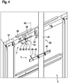
Fig. 4 shows a perspective view of a lower side final limit switch arrangement in an elevator arrangement according to an embodiment of the present invention. -
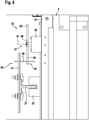
Fig. 5 shows a top view onto the final limit switch arrangement of one ofFig. 3 and4 . - The figures are only schematic and not to scale. Same reference signs refer to same or similar features.
-
Fig. 1 shows an elevator arrangement 1 with anelevator cabin 3 which may be displaced along atravel path 5 within anelevator shaft 6. Theelevator cabin 3 together with acounterweight 15 is suspended bybelts 19 which may be driven by adrive engine 17. During its motions, theelevator cabin 3 is guided along thetravel path 5 usingguide shoes 23 sliding along one ormore guide rails 21 forming astationary structure 22 within theelevator shaft 6. - In order to enabling determining whether or not the
elevator cabin 3 remains within theallowable travel path 5 or is displaced beyond an upper final travel path limit 9 or a lower final travel path limit (not shown), finallimit switch arrangements 7 are provided at or close to the upper and lower final travel path limits 9. - As visualised in both,
Fig.1 andFig. 2 , a conventional finallimit switch arrangement 7 typically comprises a roller-type limit switch 11 and acam 13. The roller -type limit switch 11 is arranged at asupport bracket 31 of theelevator cabin 3. Thecam 13 is fixed to one of the guide rails 21. - The roller-
type limit switch 11 comprises anactuation arm 27 which may be pivoted in an upward direction and in a downward direction by for example up to 30°. Upon being pivoted, theactuation arm 27 may activate or deactivate anelectric switch 25. At a cantilever end of theactuation arm 27, aroller 29 is arranged. - The
cam 13 may be made of metal profiles which, for example at a lower end directed towards thetravel path 5, form a slantedsurface 14. - Upon the
elevator cabin 3 for example being displaced upwards towards the upper final travel path limit 9, theroller 29 of the roller-type limit switch 11 will come into contact with the slantedsurface 14 at the lower end of thecam 13. Upon further displacement, theactuation arm 27 will be pivoted in a downward direction, thereby deactivating theelectric switch 25. Similarly, upon theelevator cabin 3 being displaced downwards towards and beyond the lower final travel path limit 9, theactuation arm 27 will come into contact with the slantedsurface 14 at the upper end of anothercam 13 and will be pivoted in an upward direction, thereby also deactivating theelectric switch 25. As theelectric switch 25 may be part of asafety chain 20 connected to theelevator controller 18, such the activation may result in immediately interrupting any further displacement of theelevator cabin 3. - However, the conventional roller-
type limit switch 11 and thecam 13 are relatively complex components. Furthermore, the position of thecam 13 has to be precisely aligned with the position of theroller 29 of the roller-type limit switch 11. - Accordingly, it is proposed to replace such conventional roller-
type limit switch 11 andcam 13 by a simplified finallimit switch arrangement 7 as shown inFigs. 3 to 5 . Therein, instead of the roller-type limit switch 11, across limit switch 33 is provided at theelevator cabin 3. Thiscross limit switch 33 may be attached to thesupport bracket 31 of theelevator cabin 3. For triggering suchcross limit switch 33, theconventional cam 13 may be replaced by asimplified trigger element 45. Thetrigger element 45 may be attached to anystationary structure 22 relative to thetravel path 5. For example, thetrigger element 45 may be attached to theguide rail 21. - The
cross limit switch 33 comprises anelectric switch 35 and across-type actuation element 37. Thecross-type actuation element 37 may be rotated around arotation axis 41. Upon being rotated by more than a predetermined minimum rotation angle of for example 90°, theactuation element 37 changes a switching state of theelectric switch 35 from being deactivated to being activated or vice versa. - In the example shown, the
cross-type actuation element 37 comprises fourarms 39 which all extend in a same plane being orthogonal to therotation axis 41 but in different extension directions being rectangular to each other. Allarms 39 have a same length. - The actuation element may be biased such that at least one of its arms extends to be directed into a predetermined direction such as for example into a horizontal direction. Accordingly, an
arm 39 of theactuation element 37 does not necessarily need to be actively displaced about the entire minimum rotation angle of for example 90°. Instead, it may be sufficient to displace thearm 39 by only a portion of such minimum rotation angle, for example by more than 45°, and thearm 39 will then automatically further rotate until reaching the intended biased orientation, i.e. by for example the remaining 45°. The biasing of the actuation element may be implemented using for example elastic elements such as springs pushing the actuation element towards intended biased orientations. - The
trigger element 45 comprises a fixingelement 47, such as a metal profile, being attached to theguide rail 21 and furthermore comprises arod 49. Therod 49 extends transversal or preferably rectangular to the fixingelement 47. The fixingelement 47 may be attached to theguide rail 21 or any otherstationary structure 22 using for example screws or clips. Similarly, therod 49 may be attached to the fixingelement 47 using fixation means such as screws or clips. - Both, at least one of the
arms 39 of theactuation element 37 of thecross limit switch 33 as well as therod 49 of thetrigger element 45 extend into avirtual actuation path 43. Theactuation path 43 is generally vertical and is formed by a line extending through therod 49 of thetrigger element 45, on the one hand, and through thearm 39 of theactuation element 37 of thecross limit switch 33, on the other hand. Furthermore, thetrigger element 45 is arranged at or close to one of the upper final travel path limit 9, as shown inFig. 3 , and the lower final travel path limit, as shown inFig. 4 . - Accordingly, upon the
elevator cabin 3 being displaced from a position within itstravel path 5 to a position beyond one of the final travel path limits 9, thetrigger element 45 engages with itsrod 49 with one of thearms 39 of theactuation element 37. Upon further displacement of theelevator cabin 3, theactuation element 37 is then pushed and reorientated by more than the predetermined minimum rotation angle. Thereby, theelectric switch 35 is switched from its activated state to its deactivated state. As theelectric switch 35 may be part of thesafety chain 20 monitored by theelevator controller 18, such deactivation of theelectric switch 35 may be detected by theelevator controller 18 which may then initiate suitable counteractions such as stopping further displacement of theelevator cabin 3. - In order to re-start normal operation of the elevator arrangement 1, a technician may manually control the displacement of the
elevator cabin 3 until theelevator cabin 3 is transferred back into theallowable travel path 5. Upon such displacement, therod 49 of thetrigger element 45 will again cooperate with one of thearms 39 of thecross limit switch 33. Thereby, theelectric switch 35 will be re-activated. Accordingly, thesafety chain 20 is closed again and theelevator controller 18 may reassume normal operation of the elevator arrangement 1. - The final
limit switch arrangement 7 including thecross limit switch 33 and thetrigger element 45 may be formed with simpler components and/or may be operated at relaxed operation requirements and/or relaxed alignment requirements than conventional finallimit switch arrangements 7. For example, as thearms 39 of thecross limit switch 33 and therod 49 of thetrigger element 45 extend transverse to each other, these components may be arranged within a significant positional tolerance of for example several centimetres relative to theactuation path 43. Furthermore, as theactuation element 37 of thecross limit switch 33 may be rotated in both of opposite directions, deactivation of thecross limit switch 33 may be easily implemented at both, the upper final travel path limit 9 and the lower final travel path limit, and re-activation of thecross limit switch 33 may also be easily established upon bringing theelevator cabin 3 back into theallowable travel path 5. Accordingly, the proposed finallimit switch arrangement 7 enables reduced costs, improved robustness and/or simplified installation and maintenance for the elevator arrangement 1. - Finally, it should be noted that the term "comprising" does not exclude other elements or steps and the "a" or "an" does not exclude a plurality. Also elements described in association with different embodiments may be combined. It should also be noted that reference signs in the claims should not be construed as limiting the scope of the claims.
Claims (9)
- Elevator arrangement (1) comprising:a cabin (3) being displaceable along a travel path (5); anda final limit switch arrangement (7) to be actuated upon the cabin (3) being displaced beyond a final travel path limit (9);wherein the final limit switch arrangement (7) comprises- a cross limit switch (33) being attached to the cabin (3), the cross limit switch (33) comprising an electric switch (35) and a cross-type actuation element (37), the electric switch (35) being alternately activated and deactivated upon each time the actuation element (37) is being rotated around a rotation axis (41) by more than a minimum rotation angle, the actuation element (37) comprising at least three arms (39) extending in different directions away from the rotation axis (41) such that, in every possible rotation configuration, one of the arms (39) extends in an extension direction being transversal to an actuation path (43) extending in parallel to the travel path (5); and- a trigger element (45) being arranged at a stationary position relative to the travel path (5), the trigger element (45) extending such as to cross the actuation path (43) and the extension direction.
- Elevator arrangement of claim 1, wherein the actuation element (37) comprises four arms (39) extending in directions perpendicular to each other away from the rotation axis (41).
- Elevator arrangement of one of the preceding claims, wherein all arms (39) of the actuation element (37) have a same length.
- Elevator arrangement of one of the preceding claims, wherein the actuation element (37) is biased towards orientations in which one of its arms (39) extends in an extension direction being perpendicular to the actuation path (43).
- Elevator arrangement of one of the preceding claims, wherein the trigger element (45) is attached to a guide rail (21) along which the cabin (3) is guided upon being displaced along the travel path (5).
- Elevator arrangement of one of the preceding claims, wherein the trigger element (45) comprises a fixing element (47) and a rod (49), the fixing element (47) being fixed to a stationary structure (22) within an elevator shaft (6) and the rod (49) being fixed to the fixing element (47) such as to protrude in a direction crossing the actuation path (43) and the extension direction.
- Elevator arrangement of one of the preceding claims, wherein the cross limit switch (33) and the trigger element (45) are arranged and configured such that, upon the cabin (3) being displaced beyond the final travel path limit (9), the trigger element (45) engages with one of the arms (39) of the actuation element (37) and reorients the actuation element (37) from an activated switch configuration to a deactivated switch configuration.
- Elevator arrangement of one of the preceding claims, wherein the cross limit switch (33) and the trigger element (45) are arranged and configured, such that upon the cabin (3) being displaced from a position beyond the final travel path limit (9) back to a position within the travel path (5), the trigger element (45) engages with one of the arms (39) of the actuation element (37) and reorients the actuation element (37) from a deactivated switch configuration to an activated switch configuration.
- Elevator arrangement of one of the preceding claims, wherein the cross limit switch (33) is included into an electrical safety chain of the elevator arrangement (1) such as to close the safety chain upon the cross limit switch (33) being activated and to interrupt the safety chain upon the cross limit switch (33) being deactivated.
Priority Applications (1)
| Application Number | Priority Date | Filing Date | Title |
|---|---|---|---|
| EP18152392.9A EP3514094A1 (en) | 2018-01-18 | 2018-01-18 | Elevator arrangement comprising a final limit switch arrangement with a cross limit switch |
Applications Claiming Priority (1)
| Application Number | Priority Date | Filing Date | Title |
|---|---|---|---|
| EP18152392.9A EP3514094A1 (en) | 2018-01-18 | 2018-01-18 | Elevator arrangement comprising a final limit switch arrangement with a cross limit switch |
Publications (1)
| Publication Number | Publication Date |
|---|---|
| EP3514094A1 true EP3514094A1 (en) | 2019-07-24 |
Family
ID=61007546
Family Applications (1)
| Application Number | Title | Priority Date | Filing Date |
|---|---|---|---|
| EP18152392.9A Withdrawn EP3514094A1 (en) | 2018-01-18 | 2018-01-18 | Elevator arrangement comprising a final limit switch arrangement with a cross limit switch |
Country Status (1)
| Country | Link |
|---|---|
| EP (1) | EP3514094A1 (en) |
Citations (3)
| Publication number | Priority date | Publication date | Assignee | Title |
|---|---|---|---|---|
| JPS5437677U (en) * | 1977-08-19 | 1979-03-12 | ||
| KR20100000822U (en) * | 2008-07-16 | 2010-01-26 | 이봉석 | Position limit switch case |
| CN204689283U (en) | 2015-05-12 | 2015-10-07 | 美奥电梯(苏州)有限公司 | Spacing leveling switch support in a kind of elevator |
-
2018
- 2018-01-18 EP EP18152392.9A patent/EP3514094A1/en not_active Withdrawn
Patent Citations (3)
| Publication number | Priority date | Publication date | Assignee | Title |
|---|---|---|---|---|
| JPS5437677U (en) * | 1977-08-19 | 1979-03-12 | ||
| KR20100000822U (en) * | 2008-07-16 | 2010-01-26 | 이봉석 | Position limit switch case |
| CN204689283U (en) | 2015-05-12 | 2015-10-07 | 美奥电梯(苏州)有限公司 | Spacing leveling switch support in a kind of elevator |
Similar Documents
| Publication | Publication Date | Title |
|---|---|---|
| KR101014917B1 (en) | Elevator apparatus | |
| JP4680262B2 (en) | Safety devices used in elevator systems | |
| JP5380407B2 (en) | Safety elevator | |
| JP6263552B2 (en) | Elevator safety system | |
| EP2038198B1 (en) | Retractable stop for maintaining overhead clearance above an elevator car | |
| CN104016205A (en) | Elevator device | |
| EP3628625B1 (en) | Time domain reflectometry for electrical safety chain condition based maintenance | |
| WO2013156670A1 (en) | Testing apparatus and safety arrangement | |
| WO2017119117A1 (en) | Cage movement restricting device and elevator | |
| WO2002070847A2 (en) | Door coupler and locking device | |
| CN113173478B (en) | Elevator car with camera mount | |
| US5637842A (en) | Elevator safety device | |
| EP2560182A1 (en) | Relay, control circuit, and method for controlling control circuit | |
| JP2012254866A (en) | Terminal switch device of elevator | |
| JP5086759B2 (en) | Passage chain break detection device for passenger conveyor | |
| CN118265857A (en) | System for supporting movable line receiving means, energy guiding chains or the like | |
| EP3978405B1 (en) | Elevator systems | |
| KR100891234B1 (en) | Elevator device | |
| CN109071180B (en) | elevator equipment | |
| JP2017222503A (en) | Passenger conveyor safety device | |
| JP2025001885A (en) | Position detection system for elevator and position detection method for elevator | |
| CN114394497B (en) | An elevator car leveling door opening verification and protection structure | |
| JP2010159121A (en) | Elevator | |
| JP2010024004A (en) | Abnormality detector for passenger conveyor | |
| KR20160032444A (en) | Collision prevention device for elevator |
Legal Events
| Date | Code | Title | Description |
|---|---|---|---|
| PUAI | Public reference made under article 153(3) epc to a published international application that has entered the european phase |
Free format text: ORIGINAL CODE: 0009012 |
|
| AK | Designated contracting states |
Kind code of ref document: A1 Designated state(s): AL AT BE BG CH CY CZ DE DK EE ES FI FR GB GR HR HU IE IS IT LI LT LU LV MC MK MT NL NO PL PT RO RS SE SI SK SM TR |
|
| AX | Request for extension of the european patent |
Extension state: BA ME |
|
| STAA | Information on the status of an ep patent application or granted ep patent |
Free format text: STATUS: THE APPLICATION IS DEEMED TO BE WITHDRAWN |
|
| 18D | Application deemed to be withdrawn |
Effective date: 20200125 |