EP3514064B1 - Aircraft passenger seat extended armrest - Google Patents
Aircraft passenger seat extended armrest Download PDFInfo
- Publication number
- EP3514064B1 EP3514064B1 EP19152121.0A EP19152121A EP3514064B1 EP 3514064 B1 EP3514064 B1 EP 3514064B1 EP 19152121 A EP19152121 A EP 19152121A EP 3514064 B1 EP3514064 B1 EP 3514064B1
- Authority
- EP
- European Patent Office
- Prior art keywords
- extension
- armrest
- disposed
- extension element
- elements
- Prior art date
- Legal status (The legal status is an assumption and is not a legal conclusion. Google has not performed a legal analysis and makes no representation as to the accuracy of the status listed.)
- Not-in-force
Links
Images


Classifications
-
- B—PERFORMING OPERATIONS; TRANSPORTING
- B64—AIRCRAFT; AVIATION; COSMONAUTICS
- B64D—EQUIPMENT FOR FITTING IN OR TO AIRCRAFT; FLIGHT SUITS; PARACHUTES; ARRANGEMENT OR MOUNTING OF POWER PLANTS OR PROPULSION TRANSMISSIONS IN AIRCRAFT
- B64D11/00—Passenger or crew accommodation; Flight-deck installations not otherwise provided for
- B64D11/06—Arrangements of seats, or adaptations or details specially adapted for aircraft seats
- B64D11/0639—Arrangements of seats, or adaptations or details specially adapted for aircraft seats with features for adjustment or converting of seats
- B64D11/0644—Adjustable arm rests
-
- B—PERFORMING OPERATIONS; TRANSPORTING
- B64—AIRCRAFT; AVIATION; COSMONAUTICS
- B64D—EQUIPMENT FOR FITTING IN OR TO AIRCRAFT; FLIGHT SUITS; PARACHUTES; ARRANGEMENT OR MOUNTING OF POWER PLANTS OR PROPULSION TRANSMISSIONS IN AIRCRAFT
- B64D11/00—Passenger or crew accommodation; Flight-deck installations not otherwise provided for
- B64D11/06—Arrangements of seats, or adaptations or details specially adapted for aircraft seats
- B64D11/0612—Arrangements of seats, or adaptations or details specially adapted for aircraft seats specially adapted for children
-
- B—PERFORMING OPERATIONS; TRANSPORTING
- B60—VEHICLES IN GENERAL
- B60N—SEATS SPECIALLY ADAPTED FOR VEHICLES; VEHICLE PASSENGER ACCOMMODATION NOT OTHERWISE PROVIDED FOR
- B60N2/00—Seats specially adapted for vehicles; Arrangement or mounting of seats in vehicles
- B60N2/75—Arm-rests
- B60N2/753—Arm-rests movable to an inoperative position
-
- B—PERFORMING OPERATIONS; TRANSPORTING
- B60—VEHICLES IN GENERAL
- B60N—SEATS SPECIALLY ADAPTED FOR VEHICLES; VEHICLE PASSENGER ACCOMMODATION NOT OTHERWISE PROVIDED FOR
- B60N2/00—Seats specially adapted for vehicles; Arrangement or mounting of seats in vehicles
- B60N2/75—Arm-rests
- B60N2/763—Arm-rests adjustable
-
- B—PERFORMING OPERATIONS; TRANSPORTING
- B60—VEHICLES IN GENERAL
- B60N—SEATS SPECIALLY ADAPTED FOR VEHICLES; VEHICLE PASSENGER ACCOMMODATION NOT OTHERWISE PROVIDED FOR
- B60N2/00—Seats specially adapted for vehicles; Arrangement or mounting of seats in vehicles
- B60N2/75—Arm-rests
- B60N2/763—Arm-rests adjustable
- B60N2/777—Transversal adjustment
-
- B—PERFORMING OPERATIONS; TRANSPORTING
- B64—AIRCRAFT; AVIATION; COSMONAUTICS
- B64D—EQUIPMENT FOR FITTING IN OR TO AIRCRAFT; FLIGHT SUITS; PARACHUTES; ARRANGEMENT OR MOUNTING OF POWER PLANTS OR PROPULSION TRANSMISSIONS IN AIRCRAFT
- B64D11/00—Passenger or crew accommodation; Flight-deck installations not otherwise provided for
- B64D11/06—Arrangements of seats, or adaptations or details specially adapted for aircraft seats
-
- B—PERFORMING OPERATIONS; TRANSPORTING
- B64—AIRCRAFT; AVIATION; COSMONAUTICS
- B64D—EQUIPMENT FOR FITTING IN OR TO AIRCRAFT; FLIGHT SUITS; PARACHUTES; ARRANGEMENT OR MOUNTING OF POWER PLANTS OR PROPULSION TRANSMISSIONS IN AIRCRAFT
- B64D11/00—Passenger or crew accommodation; Flight-deck installations not otherwise provided for
- B64D11/06—Arrangements of seats, or adaptations or details specially adapted for aircraft seats
- B64D11/0646—Seats characterised by special features of stationary arms, foot or head rests
Definitions
- Exemplary embodiments pertain to the art of aircraft seats and, in particular, adjustable armrests in aircraft passenger seats.
- Passenger aircraft compartments typically include several rows of seats. Between adjacent seats are armrests.
- the armrest is typically only suitable for resting one forearm of one passenger only.
- the passengers in the adjacent seats are expected to use the common armrest in between them.
- the passengers in the middle seats end up using the common armrest on both sides. In short, there is not enough space for both the passengers to use at the same time and simultaneous use of an armrest by two co-passengers causes discomfort to both involved.
- each seat In areas of the plane where more space is allowed (e.g., first class), each seat includes two dedicated armrests. However, in more space constrained regions of the aircraft (e.g., coach), providing such armrests is not practicable.
- US 2014/0217798 A1 discloses an armrest expansion device. At least one planar housing of the device may extend the useable area available as an armrest.
- an aircraft seat armrest as claimed in claim 1 is provided.
- a second of the two extension elements may be movable from the first, closed, position where it is disposed below the armrest portion and the second, open, position wherein the second extension element is adjacent to the armrest portion.
- the armrest may also include a second locking mechanism disposed on the second extension element that maintains the second extension element in the open position after it has been moved from the closed position to the open position.
- the first and second locking mechanisms may be bolt latches.
- the first and second locking mechanisms may include bolts that mate with a bolt retention element disposed on the armrest portion.
- the bolt retention element may be a staple disposed on a bottom of the armrest portion.
- the first and second arm extension retention elements may be magnets and the first and second extension retention element may be formed of magnetic material.
- the first and second arm extension retention elements may be formed of magnetic material and the first and second extension retention element may be magnets.
- the two extension elements may be coupled to the armrest portion by hinges.
- the method may include providing a second locking mechanism disposed on the second extension element that can maintain the second extension element in the open position after it has been moved from the closed position to the open position.
- the first and second locking mechanisms may be bolt latches.
- the first and second locking mechanisms may include bolt that mate with a bolt retention element disposed on the armrest portion.
- the method may include providing a second arm extension retention element on the first arm extension.
- the method may include providing a second extension retention element on the armrest portion that mates with the second arm extension retention element that maintains the second extension element in the closed position.
- Aircraft 2 includes a fuselage 4 extending from a nose portion 6 to a tail portion 8 through a body portion 10.
- Body portion 10 houses an aircraft cabin 14 that includes a crew compartment 15 and a passenger compartment 16.
- Body portion 10 supports a first wing 17 and a second wing 18.
- First wing 17 extends from a first root portion 20 to a first tip portion 21 through a first airfoil portion 23.
- First airfoil portion 23 includes a leading edge 25 and a trailing edge 26.
- Second wing 18 extends from a second root portion (not shown) to a second tip portion 31 through a second airfoil portion 33.
- Second airfoil portion 33 includes a leading edge 35 and a trailing edge 36.
- Tail portion 8 includes a stabilizer 38.
- Aircraft 2 includes one or more seats 40 in the passenger compartment 16 of the aircraft.
- the seats 40 may also be mounted within the crew compartment 15.
- the seats 40 may also be mounted within a building and/or within various types of vehicles including but not limited to automotive, aerospace, naval, locomotive, and railway.
- the seat 40 has an adjustable armrest in one embodiment.
- the aircraft 2 includes at least two adjacent seats 40.
- FIG. 2 is a simplified version of a seat 40 according to one embodiment.
- the seat 40 includes a seat back 202 and a seating portion 204.
- the seat 40 also included a frame 206.
- the frame 206 could carry one or more adjacent seats in one embodiment or be attached to another frame that allows for another seat to be carried.
- the combination of the adjacent seats includes a single armrest 210. That is, one seat 40 may include an armrest while an adjacent seat 40 does not so that the two adjacent seats must share.
- Such an armrest 210 in the prior art is suitable for a single use only. Simultaneous use of an armrest by two co-passengers is not possible and, as a result, adjacent users may become frustrated and annoyed because their armrest is in use by a neighbor. In order to improve passenger comfort in adjacent seats, there is a need of foldable extension to the armrest for the middle seats to create more armrest space.
- FIG. 3 shows an example of an armrest 302 according to one embodiment.
- the armrest 302 is attached to or otherwise accessible by an occupant in a middle seat.
- the armrest 302 could be attached to any seat and, in particular, to an armrest between any two adjacent seats.
- the armrest 302 can replace the armrest 210 shown in FIG. 2 .
- the armrest 302 includes a top portion 304.
- the top portion 304 can be same or similar to the top of a prior art armrest.
- Attached to the armrest 302 is an armrest extension 306 that can rotate relative to the armrest extension.
- the armrest extension 306 includes two portions 306a/306b.
- the armrest 302 and the extensions are attached to one another by one or more rotatable fasteners 308.
- the fasteners 308 are hinges.
- the top portion has an area.
- the area of the top of the unit comprising the top portion 304 and tops of the extensions 306a/306b can be roughly twice the area of the top portion 304 considered alone.
- FIG. 3 Also illustrated in FIG. 3 are two locking mechanisms 312a/312b. The location of these locking mechanisms can be varied from what is shown in FIG. 3 . As illustrated, the first and second locking mechanisms 312a/312b are located at or near a front 320 of the armrest 302. The third locking mechanism 310a ( FIG. 4 ) could be omitted on one embodiment but if included, it can located further away from the front 320 of the armrest 302. In another embodiment, the first and second locking mechanisms 312a/312b can be omitted and a third locking mechanism 310a and fourth locking mechanism 310b (see FIG. 5 ) can be the only locking mechanism that hold the extensions 306a/306b in the open position.
- the extensions 306a/306b can be moved in the directions shown by arrows A and B, respectively, in FIG. 3 . As illustrated in FIG. 3 , the extensions 306a/306b are below the armrest 302.
- a portion of the first and third locking mechanisms 310a/312a can move in direction C ( FIG. 4 ) and a portion of the second locking mechanism 312b can move in direction D ( FIG. 4 ) to lock the extensions 306a/306b in place.
- the extensions 306a/306b are adjacent to the armrest 302.
- the locking mechanisms 312a/312b, 310a/310b are bolt latches.
- the bolt latches 312a/312b are located further from the front 320 of the armrest 302 in FIG. 5 as comparted to FIG. 4 to illustrate different placement options for the latches.
- the latches are secured to a bottom 502a/502b of the respective extensions.
- Each bolt latch (shown as element 600 in FIG. 6 ), includes a faceplate 602 through which one or more fasteners such as screw 604 can pass to attach it to the bottom 502a/502b of the extensions 306.
- the latch 600 can also include a moveable bolt 608 with a bolt throw 610.
- the bolt can pass into a bolt retention element 612 in one embodiment.
- the bolt retention element 612 can be staple in one embodiment.
- the latch 600 is attached to the bottom of the extensions such that the bolt 608 enters a hole or other depression in a side of the armrest 302 that forms the bolt retention element 612.
- An example of such a hole is shown in phantom by element 620 in FIG. 3 .
- the latch 600 also includes a release mechanism 614 that allows the bolt 608 to disengage from the bolt retention element 612.
- the armrest 302 includes one or more extension retention elements 540 that serve to keep the extensions 306a/306b in the closed position.
- the arm extension retention elements 540 are magnets that engage with extension retention elements 542 made of a magnetic material disposed on the bottom of the extensions 306a/306b.
- the arm extension retention elements 540 are made of a magnetic material that engage with extension retention elements 542 that are formed of magnets and disposed on the bottom of the extensions 306a/306b.
Landscapes
- Engineering & Computer Science (AREA)
- Aviation & Aerospace Engineering (AREA)
- Transportation (AREA)
- Mechanical Engineering (AREA)
- Health & Medical Sciences (AREA)
- Child & Adolescent Psychology (AREA)
- General Health & Medical Sciences (AREA)
- Seats For Vehicles (AREA)
Description
- Exemplary embodiments pertain to the art of aircraft seats and, in particular, adjustable armrests in aircraft passenger seats.
- Passenger aircraft compartments typically include several rows of seats. Between adjacent seats are armrests. The armrest is typically only suitable for resting one forearm of one passenger only. Often, the passengers in the adjacent seats are expected to use the common armrest in between them. The passengers in the middle seats end up using the common armrest on both sides. In short, there is not enough space for both the passengers to use at the same time and simultaneous use of an armrest by two co-passengers causes discomfort to both involved.
- In areas of the plane where more space is allowed (e.g., first class), each seat includes two dedicated armrests. However, in more space constrained regions of the aircraft (e.g., coach), providing such armrests is not practicable.
-
US 2014/0217798 A1 discloses an armrest expansion device. At least one planar housing of the device may extend the useable area available as an armrest. - From a first aspect, an aircraft seat armrest as claimed in claim 1 is provided.
- A second of the two extension elements may be movable from the first, closed, position where it is disposed below the armrest portion and the second, open, position wherein the second extension element is adjacent to the armrest portion. The armrest may also include a second locking mechanism disposed on the second extension element that maintains the second extension element in the open position after it has been moved from the closed position to the open position.
- The first and second locking mechanisms may be bolt latches.
- The first and second locking mechanisms may include bolts that mate with a bolt retention element disposed on the armrest portion.
- The bolt retention element may be a staple disposed on a bottom of the armrest portion.
- The first and second arm extension retention elements may be magnets and the first and second extension retention element may be formed of magnetic material.
- The first and second arm extension retention elements may be formed of magnetic material and the first and second extension retention element may be magnets.
- The two extension elements may be coupled to the armrest portion by hinges.
- From a further aspect, a method of expanding an aircraft armrest as claimed in claim 11 is provided.
- The method may include providing a second locking mechanism disposed on the second extension element that can maintain the second extension element in the open position after it has been moved from the closed position to the open position.
- The first and second locking mechanisms may be bolt latches.
- The first and second locking mechanisms may include bolt that mate with a bolt retention element disposed on the armrest portion.
- The method may include providing a second arm extension retention element on the first arm extension.
- The method may include providing a second extension retention element on the armrest portion that mates with the second arm extension retention element that maintains the second extension element in the closed position.
- The following descriptions should not be considered limiting in any way. With reference to the accompanying drawings, like elements are numbered alike:
-
FIG. 1 is a perspective view of an aircraft; -
FIG. 2 is a side-view of a prior art aircraft seat; -
FIG. 3 shows an expandable armrest in a closed position; -
FIG. 4 shows an expandable armrest in an "open" or "expanded position; -
FIG. 5 shows a bottom view of an armrest in an expanded position and the locking members that keep it in the expanded position as well as members that keep it in the closed position; and -
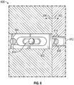
FIG. 6 shows a latch. - A detailed description of one or more embodiments of the disclosed apparatus and method are presented herein by way of exemplification and not limitation with reference to the Figures.
- Referring now to
FIG. 1 , which shows a perspective view of an aircraft 2 that may incorporate embodiments of the present disclosure. Aircraft 2 includes afuselage 4 extending from a nose portion 6 to a tail portion 8 through abody portion 10.Body portion 10 houses anaircraft cabin 14 that includes acrew compartment 15 and a passenger compartment 16.Body portion 10 supports afirst wing 17 and asecond wing 18.First wing 17 extends from afirst root portion 20 to a first tip portion 21 through afirst airfoil portion 23.First airfoil portion 23 includes a leadingedge 25 and atrailing edge 26.Second wing 18 extends from a second root portion (not shown) to asecond tip portion 31 through asecond airfoil portion 33.Second airfoil portion 33 includes a leadingedge 35 and atrailing edge 36. Tail portion 8 includes astabilizer 38. Aircraft 2 includes one ormore seats 40 in the passenger compartment 16 of the aircraft. Theseats 40 may also be mounted within thecrew compartment 15. As will be appreciated by those of skill in the art, theseats 40 may also be mounted within a building and/or within various types of vehicles including but not limited to automotive, aerospace, naval, locomotive, and railway. As detailed further below, theseat 40 has an adjustable armrest in one embodiment. As shown, the aircraft 2 includes at least twoadjacent seats 40. -
FIG. 2 is a simplified version of aseat 40 according to one embodiment. Theseat 40 includes aseat back 202 and aseating portion 204. Theseat 40 also included aframe 206. Theframe 206 could carry one or more adjacent seats in one embodiment or be attached to another frame that allows for another seat to be carried. As discussed above, when two seats are adjacent, the combination of the adjacent seats includes asingle armrest 210. That is, oneseat 40 may include an armrest while anadjacent seat 40 does not so that the two adjacent seats must share. - Such an
armrest 210 in the prior art is suitable for a single use only. Simultaneous use of an armrest by two co-passengers is not possible and, as a result, adjacent users may become frustrated and annoyed because their armrest is in use by a neighbor. In order to improve passenger comfort in adjacent seats, there is a need of foldable extension to the armrest for the middle seats to create more armrest space. -
FIG. 3 shows an example of anarmrest 302 according to one embodiment. In one embodiment, thearmrest 302 is attached to or otherwise accessible by an occupant in a middle seat. However, thearmrest 302 could be attached to any seat and, in particular, to an armrest between any two adjacent seats. Thearmrest 302 can replace thearmrest 210 shown inFIG. 2 . - The
armrest 302 includes atop portion 304. Thetop portion 304 can be same or similar to the top of a prior art armrest. Attached to thearmrest 302 is anarmrest extension 306 that can rotate relative to the armrest extension. As illustrated, thearmrest extension 306 includes twoportions 306a/306b. Thearmrest 302 and the extensions are attached to one another by one or morerotatable fasteners 308. In one embodiment, thefasteners 308 are hinges. - The one embodiment, the top portion has an area. When the
armrest extensions 306 are move to their open state (seeFIG. 4 ), the area of the top of the unit comprising thetop portion 304 and tops of theextensions 306a/306b can be roughly twice the area of thetop portion 304 considered alone. - Also illustrated in
FIG. 3 are two lockingmechanisms 312a/312b. The location of these locking mechanisms can be varied from what is shown inFIG. 3 . As illustrated, the first andsecond locking mechanisms 312a/312b are located at or near afront 320 of thearmrest 302. Thethird locking mechanism 310a (FIG. 4 ) could be omitted on one embodiment but if included, it can located further away from thefront 320 of thearmrest 302. In another embodiment, the first andsecond locking mechanisms 312a/312b can be omitted and athird locking mechanism 310a andfourth locking mechanism 310b (seeFIG. 5 ) can be the only locking mechanism that hold theextensions 306a/306b in the open position. - To move from the closed position of
FIG. 3 to the open position ofFIG. 4 , theextensions 306a/306b can be moved in the directions shown by arrows A and B, respectively, inFIG. 3 . As illustrated inFIG. 3 , theextensions 306a/306b are below thearmrest 302. - After the
extensions 306a/306b are moved in the directions shown by arrows A and B, respectively, inFIG. 3 , a portion of the first andthird locking mechanisms 310a/312a can move in direction C (FIG. 4 ) and a portion of thesecond locking mechanism 312b can move in direction D (FIG. 4 ) to lock theextensions 306a/306b in place. InFIG. 4 , theextensions 306a/306b are adjacent to thearmrest 302. - In one embodiment, and as best seen in
FIGs. 5 and6 , the lockingmechanisms 312a/312b, 310a/310b are bolt latches. The bolt latches 312a/312b are located further from thefront 320 of thearmrest 302 inFIG. 5 as comparted toFIG. 4 to illustrate different placement options for the latches. The latches are secured to abottom 502a/502b of the respective extensions. - Each bolt latch (shown as
element 600 inFIG. 6 ), includes afaceplate 602 through which one or more fasteners such asscrew 604 can pass to attach it to thebottom 502a/502b of theextensions 306. - The
latch 600 can also include amoveable bolt 608 with abolt throw 610. The bolt can pass into abolt retention element 612 in one embodiment. Thebolt retention element 612 can be staple in one embodiment. - In one embodiment, the
latch 600 is attached to the bottom of the extensions such that thebolt 608 enters a hole or other depression in a side of thearmrest 302 that forms thebolt retention element 612. An example of such a hole is shown in phantom byelement 620 inFIG. 3 . - The
latch 600 also includes arelease mechanism 614 that allows thebolt 608 to disengage from thebolt retention element 612. - Referring again to
FIG. 5 , thearmrest 302 includes one or moreextension retention elements 540 that serve to keep theextensions 306a/306b in the closed position. In one embodiment, the armextension retention elements 540 are magnets that engage withextension retention elements 542 made of a magnetic material disposed on the bottom of theextensions 306a/306b. - In another embodiment, the arm
extension retention elements 540 are made of a magnetic material that engage withextension retention elements 542 that are formed of magnets and disposed on the bottom of theextensions 306a/306b. - The term "about" is intended to include the degree of error associated with measurement of the particular quantity based upon the equipment available at the time of filing the application.
- The terminology used herein is for the purpose of describing particular embodiments only and is not intended to be limiting of the present disclosure. As used herein, the singular forms "a", "an" and "the" are intended to include the plural forms as well, unless the context clearly indicates otherwise. It will be further understood that the terms "comprises" and/or "comprising," when used in this specification, specify the presence of stated features, integers, steps, operations, elements, and/or components, but do not preclude the presence or addition of one or more other features, integers, steps, operations, element components, and/or groups thereof.
- While the present invention has been described with reference to an exemplary embodiment or embodiments, it will be understood by those skilled in the art that various changes may be made without departing from the scope of the present invention as defined by the appended claims. In addition, many modifications may be made to adapt a particular situation or material to the teachings of the present invention without departing from the scope of the claims. Therefore, it is intended that the present invention not be limited to the particular embodiment disclosed as the best mode contemplated for carrying out this present invention, but that the present invention will include all embodiments falling within the scope of the claims.
Claims (15)
- An aircraft seat armrest (302) including:an armrest portion (304) having a top for resting a forearm of a passenger and a bottom that is opposite to the top of the armrest portion;two extension elements (306a, 306b) coupled to the armrest portion (304) on opposite sides thereof, each extension element having a top for resting the forearm of the passenger and a bottom that is opposite to the top of the extension element;wherein a first of the two extension elements (306a, 306b) is rotatable from a first, closed, position where it is disposed below the armrest portion (304) to a second, open, position wherein the first extension element is adjacent to the armrest portion (304);a first locking mechanism (312a) disposed on the first extension element that maintains the first extension element in the open position after it has been moved from the closed position to the open position; anda first extension element retention element (540) disposed on the bottom of the first extension element (306a);characterised in that the aircraft seat armrest (302) includes:
a first extension retention element (542) disposed on the bottom of the armrest portion (304) that engages with the first extension element retention element (540) when the first of the two extension elements (306a, 306b) is in the closed position and maintains the first of the two extension elements (306a, 306b) in the closed position. - The aircraft seat armrest (302) of claim 1, wherein a second of the two extension elements is movable from a first, closed position where it is disposed below the armrest portion (304) to a second, open, position wherein the second extension element (306b) is adjacent to the armrest portion (304); and further comprising:
a second locking mechanism (312b) disposed on the second extension element (306b) that maintains the second extension element in the open position after it has been moved from the closed position to the open position. - The aircraft seat armrest (302) of claim 2, wherein the first and second locking mechanisms (312a, 312b) are bolt latches.
- The aircraft seat armrest (302) of claim 3, wherein the first and second locking mechanisms (312a, 312b) include bolts that mate with a bolt retention element disposed on the armrest portion (304).
- The aircraft seat armrest (302) of claim 4, wherein the bolt retention element is a staple disposed on a bottom of the armrest portion (304).
- The aircraft seat armrest (302) of any of claims 2 to 5, further comprising:
a second extension element retention element (540) disposed on the bottom of the second extension element (306b). - The aircraft seat armrest (302) of claim 6, further comprising:
a second extension retention element (542) disposed on the bottom of the armrest portion (304) that mates with the second extension element retention element (540) that maintains the second extension element (306b) in the closed position. - The aircraft seat armrest (302) of claim 7, wherein the first and second extension element retention elements (540) are magnets and the first and second extension retention elements (542) are formed of magnetic material.
- The aircraft seat armrest (302) of claim 7, wherein the first and second extension element retention elements (540) are formed of magnetic material and the first and second extension retention elements (542) are magnets.
- The aircraft seat armrest (302) of any preceding claim, wherein the two extension elements (306a, 306b) are coupled to the armrest portion by hinges (308).
- A method of expanding an aircraft seat armrest (302), the method comprising:providing an armrest portion (304) having a top for resting a forearm of a passenger and a bottom that is opposite to the top of the armrest portion;coupling two extension elements (306a, 306b) to the armrest portion (304) on opposite sides thereof such that they can rotate relative to the armrest portion, each extension element having a top for resting the forearm of the passenger and a bottom that is opposite to the top of the extension element;wherein the two extension elements (306a, 306b) are coupled such that a first of the two extension elements can move from a first, closed, position where it is disposed below the armrest portion (304) to a second open, position wherein the first extension element is adjacent to the armrest portion (304); andproviding the first extension element (306a) with a first locking mechanism (312a) disposed on the first extension element that can maintain the first extension element in the open position; andproviding a first extension element retention element (540) disposed on the bottom of the first extension element (306a);the method characterised by providing:
a first extension retention element (542) disposed on the bottom of the armrest portion (304) that engages with the first extension element retention element (540) when the first of the two extension elements is in the closed position and maintains the first of the two extension elements in the closed position. - The method of claim 11, further comprising:
providing a second locking mechanism (312b) disposed on the second extension element (306b) that can maintain the second extension element in an open position after it has been moved from a closed position to an open position. - The method of claim 12, wherein the first and second locking mechanisms (312a, 312b) are bolt latches.
- The method of claim 13, wherein the first and second locking mechanisms (312a, 312b) include bolts that mate with a bolt retention element disposed on the armrest portion (304).
- The method of any of claims 11 to 14, further comprising:
providing a second extension element retention element (540) on the second extension element (306b).
Applications Claiming Priority (1)
| Application Number | Priority Date | Filing Date | Title |
|---|---|---|---|
| IN201811002320 | 2018-01-19 |
Publications (2)
| Publication Number | Publication Date |
|---|---|
| EP3514064A1 EP3514064A1 (en) | 2019-07-24 |
| EP3514064B1 true EP3514064B1 (en) | 2021-10-06 |
Family
ID=65033525
Family Applications (1)
| Application Number | Title | Priority Date | Filing Date |
|---|---|---|---|
| EP19152121.0A Not-in-force EP3514064B1 (en) | 2018-01-19 | 2019-01-16 | Aircraft passenger seat extended armrest |
Country Status (4)
| Country | Link |
|---|---|
| US (1) | US10934002B2 (en) |
| EP (1) | EP3514064B1 (en) |
| BR (1) | BR102019000727A8 (en) |
| CA (1) | CA3029716A1 (en) |
Families Citing this family (3)
| Publication number | Priority date | Publication date | Assignee | Title |
|---|---|---|---|---|
| WO2021080628A1 (en) * | 2019-10-25 | 2021-04-29 | Safran Seats Usa Llc | Passenger seat armrest with a multi-zone top surface |
| US11147384B1 (en) * | 2020-09-30 | 2021-10-19 | Industrias Nortecaucanas S.A.S. | Dynamic privacy barrier system |
| CN118545141A (en) * | 2023-02-24 | 2024-08-27 | 明门(中国)幼童用品有限公司 | Armrest Mounting Units, Carts and Seat Assemblies |
Family Cites Families (17)
| Publication number | Priority date | Publication date | Assignee | Title |
|---|---|---|---|---|
| US5795025A (en) | 1996-08-30 | 1998-08-18 | Aircraft Modular Products, Inc. | Retractable armrest for an aircraft seat |
| US10556523B1 (en) * | 2007-05-07 | 2020-02-11 | Arjuna Indraeswaran Rajasingham | Vehicle occupant support |
| US20060006704A1 (en) | 2003-12-15 | 2006-01-12 | Be Aerospace, Inc. | Vehicle seating with storage feature |
| KR200367088Y1 (en) | 2004-08-25 | 2004-11-08 | 박천형 | Armchair of which armrests sliding severally |
| GB2455130B (en) | 2007-11-29 | 2011-11-02 | James Shing Hin Lee | Armrest for multiple seating |
| US8146999B2 (en) | 2009-09-02 | 2012-04-03 | AMI Industries. Inc | Aircraft seat with adjustable armrest |
| EP2504233B1 (en) * | 2009-11-23 | 2017-08-23 | Zodiac Seats US LLC | Table stop assembly |
| US20130147245A1 (en) * | 2011-12-13 | 2013-06-13 | Javier Torres | Padded Armrest |
| US9045062B2 (en) * | 2012-11-16 | 2015-06-02 | Zodiac Seats Us Llc | Reversible airline seat |
| US9468302B2 (en) | 2013-02-04 | 2016-10-18 | Isaac Negusse | Armrest expansion device |
| US9227539B2 (en) | 2013-10-03 | 2016-01-05 | Grady Locke | Portable padded armrest |
| BR102013032476B1 (en) | 2013-12-17 | 2021-01-05 | Embraer S.A. | seat comprising a structure for armrests |
| EP2899066B1 (en) | 2014-01-28 | 2019-09-25 | Airbus Defence and Space GmbH | Armrest and seat arrangement comprising the same |
| WO2015149120A1 (en) | 2014-03-29 | 2015-10-08 | Prism Ip Licensing Co Pty Ltd | A shared armrest |
| EP3126237B1 (en) * | 2014-04-03 | 2018-10-10 | Zodiac Seats US LLC | Center console side opening doors and integrated armrest cocktail tray |
| US9693634B2 (en) * | 2014-11-13 | 2017-07-04 | Charles Patrick Smith | Expandable chair |
| TWI572527B (en) | 2015-06-04 | 2017-03-01 | 艾爾康太平洋股份有限公司 | Armrest structure and aircraft seat assebly thereof |
-
2018
- 2018-03-27 US US15/936,497 patent/US10934002B2/en not_active Expired - Fee Related
-
2019
- 2019-01-10 CA CA3029716A patent/CA3029716A1/en active Pending
- 2019-01-14 BR BR102019000727A patent/BR102019000727A8/en not_active Application Discontinuation
- 2019-01-16 EP EP19152121.0A patent/EP3514064B1/en not_active Not-in-force
Non-Patent Citations (1)
| Title |
|---|
| None * |
Also Published As
| Publication number | Publication date |
|---|---|
| CA3029716A1 (en) | 2019-07-19 |
| US20190225342A1 (en) | 2019-07-25 |
| EP3514064A1 (en) | 2019-07-24 |
| US10934002B2 (en) | 2021-03-02 |
| BR102019000727A8 (en) | 2023-04-04 |
| BR102019000727A2 (en) | 2019-11-05 |
Similar Documents
| Publication | Publication Date | Title |
|---|---|---|
| EP3572325B1 (en) | Deployable partition systems and methods for seat assemblies | |
| US11046437B2 (en) | Forward-facing aircraft passenger suite with all aisle access | |
| CN106965937B (en) | Extensible door installing type seat | |
| EP3514064B1 (en) | Aircraft passenger seat extended armrest | |
| EP2726373B1 (en) | Multipurpose tray | |
| US10737788B2 (en) | Systems and methods for adaptively positioning a cross-aisle curtain header assembly within a vehicle | |
| US10696410B2 (en) | Seat assembly having a deployable headrest | |
| US20110042514A1 (en) | Movable Fastening Unit For A Seat Frame In An Aircraft | |
| US10974834B2 (en) | Separable vehicle cabin privacy partition assemblies which allow for emergency egress | |
| US11673671B2 (en) | Passenger seating arrangement | |
| US12202605B2 (en) | Retractable divider for passenger seat | |
| US20200307806A1 (en) | Seat adjustment system and method | |
| EP4197910B1 (en) | Reconfigurable seat assembly | |
| US10259586B2 (en) | Deployable seat assembly, system, and method for an interior cabin of a vehicle | |
| CN100548801C (en) | Partitions for aircraft compartments | |
| US20210107656A1 (en) | Seating systems and methods for an internal cabin of an aircraft | |
| US11572177B2 (en) | Seat cable adjustment system and method | |
| US12090097B2 (en) | Platform system for securing a wheelchair in position within an internal cabin of a vehicle | |
| US20180065751A1 (en) | Side-facing belted aircraft seats | |
| US10926881B2 (en) | Seat adjustment system and method | |
| US10814987B2 (en) | Reclining cushion assembly | |
| EP4299443A1 (en) | System including stowage pouch | |
| US20240253789A1 (en) | Transformable seat systems and methods for an internal cabin of an aircraft | |
| US11987362B2 (en) | Galley cart securing systems and methods | |
| BR102019021825B1 (en) | RECLINING CUSHION SET, SEAT, AND METHOD FOR RECLINING A SEAT |
Legal Events
| Date | Code | Title | Description |
|---|---|---|---|
| PUAI | Public reference made under article 153(3) epc to a published international application that has entered the european phase |
Free format text: ORIGINAL CODE: 0009012 |
|
| STAA | Information on the status of an ep patent application or granted ep patent |
Free format text: STATUS: THE APPLICATION HAS BEEN PUBLISHED |
|
| AK | Designated contracting states |
Kind code of ref document: A1 Designated state(s): AL AT BE BG CH CY CZ DE DK EE ES FI FR GB GR HR HU IE IS IT LI LT LU LV MC MK MT NL NO PL PT RO RS SE SI SK SM TR |
|
| AX | Request for extension of the european patent |
Extension state: BA ME |
|
| STAA | Information on the status of an ep patent application or granted ep patent |
Free format text: STATUS: REQUEST FOR EXAMINATION WAS MADE |
|
| 17P | Request for examination filed |
Effective date: 20200124 |
|
| RBV | Designated contracting states (corrected) |
Designated state(s): AL AT BE BG CH CY CZ DE DK EE ES FI FR GB GR HR HU IE IS IT LI LT LU LV MC MK MT NL NO PL PT RO RS SE SI SK SM TR |
|
| STAA | Information on the status of an ep patent application or granted ep patent |
Free format text: STATUS: EXAMINATION IS IN PROGRESS |
|
| 17Q | First examination report despatched |
Effective date: 20200616 |
|
| GRAP | Despatch of communication of intention to grant a patent |
Free format text: ORIGINAL CODE: EPIDOSNIGR1 |
|
| STAA | Information on the status of an ep patent application or granted ep patent |
Free format text: STATUS: GRANT OF PATENT IS INTENDED |
|
| RIC1 | Information provided on ipc code assigned before grant |
Ipc: B64D 11/06 20060101AFI20210326BHEP Ipc: B60N 2/75 20180101ALN20210326BHEP |
|
| INTG | Intention to grant announced |
Effective date: 20210423 |
|
| GRAS | Grant fee paid |
Free format text: ORIGINAL CODE: EPIDOSNIGR3 |
|
| GRAA | (expected) grant |
Free format text: ORIGINAL CODE: 0009210 |
|
| STAA | Information on the status of an ep patent application or granted ep patent |
Free format text: STATUS: THE PATENT HAS BEEN GRANTED |
|
| AK | Designated contracting states |
Kind code of ref document: B1 Designated state(s): AL AT BE BG CH CY CZ DE DK EE ES FI FR GB GR HR HU IE IS IT LI LT LU LV MC MK MT NL NO PL PT RO RS SE SI SK SM TR |
|
| REG | Reference to a national code |
Ref country code: GB Ref legal event code: FG4D |
|
| REG | Reference to a national code |
Ref country code: CH Ref legal event code: EP Ref country code: AT Ref legal event code: REF Ref document number: 1436025 Country of ref document: AT Kind code of ref document: T Effective date: 20211015 |
|
| REG | Reference to a national code |
Ref country code: DE Ref legal event code: R096 Ref document number: 602019008056 Country of ref document: DE |
|
| REG | Reference to a national code |
Ref country code: IE Ref legal event code: FG4D |
|
| REG | Reference to a national code |
Ref country code: LT Ref legal event code: MG9D |
|
| REG | Reference to a national code |
Ref country code: NL Ref legal event code: MP Effective date: 20211006 |
|
| REG | Reference to a national code |
Ref country code: AT Ref legal event code: MK05 Ref document number: 1436025 Country of ref document: AT Kind code of ref document: T Effective date: 20211006 |
|
| PG25 | Lapsed in a contracting state [announced via postgrant information from national office to epo] |
Ref country code: RS Free format text: LAPSE BECAUSE OF FAILURE TO SUBMIT A TRANSLATION OF THE DESCRIPTION OR TO PAY THE FEE WITHIN THE PRESCRIBED TIME-LIMIT Effective date: 20211006 Ref country code: LT Free format text: LAPSE BECAUSE OF FAILURE TO SUBMIT A TRANSLATION OF THE DESCRIPTION OR TO PAY THE FEE WITHIN THE PRESCRIBED TIME-LIMIT Effective date: 20211006 Ref country code: FI Free format text: LAPSE BECAUSE OF FAILURE TO SUBMIT A TRANSLATION OF THE DESCRIPTION OR TO PAY THE FEE WITHIN THE PRESCRIBED TIME-LIMIT Effective date: 20211006 Ref country code: BG Free format text: LAPSE BECAUSE OF FAILURE TO SUBMIT A TRANSLATION OF THE DESCRIPTION OR TO PAY THE FEE WITHIN THE PRESCRIBED TIME-LIMIT Effective date: 20220106 Ref country code: AT Free format text: LAPSE BECAUSE OF FAILURE TO SUBMIT A TRANSLATION OF THE DESCRIPTION OR TO PAY THE FEE WITHIN THE PRESCRIBED TIME-LIMIT Effective date: 20211006 |
|
| PG25 | Lapsed in a contracting state [announced via postgrant information from national office to epo] |
Ref country code: IS Free format text: LAPSE BECAUSE OF FAILURE TO SUBMIT A TRANSLATION OF THE DESCRIPTION OR TO PAY THE FEE WITHIN THE PRESCRIBED TIME-LIMIT Effective date: 20220206 Ref country code: SE Free format text: LAPSE BECAUSE OF FAILURE TO SUBMIT A TRANSLATION OF THE DESCRIPTION OR TO PAY THE FEE WITHIN THE PRESCRIBED TIME-LIMIT Effective date: 20211006 Ref country code: PT Free format text: LAPSE BECAUSE OF FAILURE TO SUBMIT A TRANSLATION OF THE DESCRIPTION OR TO PAY THE FEE WITHIN THE PRESCRIBED TIME-LIMIT Effective date: 20220207 Ref country code: PL Free format text: LAPSE BECAUSE OF FAILURE TO SUBMIT A TRANSLATION OF THE DESCRIPTION OR TO PAY THE FEE WITHIN THE PRESCRIBED TIME-LIMIT Effective date: 20211006 Ref country code: NO Free format text: LAPSE BECAUSE OF FAILURE TO SUBMIT A TRANSLATION OF THE DESCRIPTION OR TO PAY THE FEE WITHIN THE PRESCRIBED TIME-LIMIT Effective date: 20220106 Ref country code: NL Free format text: LAPSE BECAUSE OF FAILURE TO SUBMIT A TRANSLATION OF THE DESCRIPTION OR TO PAY THE FEE WITHIN THE PRESCRIBED TIME-LIMIT Effective date: 20211006 Ref country code: LV Free format text: LAPSE BECAUSE OF FAILURE TO SUBMIT A TRANSLATION OF THE DESCRIPTION OR TO PAY THE FEE WITHIN THE PRESCRIBED TIME-LIMIT Effective date: 20211006 Ref country code: HR Free format text: LAPSE BECAUSE OF FAILURE TO SUBMIT A TRANSLATION OF THE DESCRIPTION OR TO PAY THE FEE WITHIN THE PRESCRIBED TIME-LIMIT Effective date: 20211006 Ref country code: GR Free format text: LAPSE BECAUSE OF FAILURE TO SUBMIT A TRANSLATION OF THE DESCRIPTION OR TO PAY THE FEE WITHIN THE PRESCRIBED TIME-LIMIT Effective date: 20220107 Ref country code: ES Free format text: LAPSE BECAUSE OF FAILURE TO SUBMIT A TRANSLATION OF THE DESCRIPTION OR TO PAY THE FEE WITHIN THE PRESCRIBED TIME-LIMIT Effective date: 20211006 |
|
| REG | Reference to a national code |
Ref country code: DE Ref legal event code: R097 Ref document number: 602019008056 Country of ref document: DE |
|
| PG25 | Lapsed in a contracting state [announced via postgrant information from national office to epo] |
Ref country code: SM Free format text: LAPSE BECAUSE OF FAILURE TO SUBMIT A TRANSLATION OF THE DESCRIPTION OR TO PAY THE FEE WITHIN THE PRESCRIBED TIME-LIMIT Effective date: 20211006 Ref country code: SK Free format text: LAPSE BECAUSE OF FAILURE TO SUBMIT A TRANSLATION OF THE DESCRIPTION OR TO PAY THE FEE WITHIN THE PRESCRIBED TIME-LIMIT Effective date: 20211006 Ref country code: RO Free format text: LAPSE BECAUSE OF FAILURE TO SUBMIT A TRANSLATION OF THE DESCRIPTION OR TO PAY THE FEE WITHIN THE PRESCRIBED TIME-LIMIT Effective date: 20211006 Ref country code: EE Free format text: LAPSE BECAUSE OF FAILURE TO SUBMIT A TRANSLATION OF THE DESCRIPTION OR TO PAY THE FEE WITHIN THE PRESCRIBED TIME-LIMIT Effective date: 20211006 Ref country code: DK Free format text: LAPSE BECAUSE OF FAILURE TO SUBMIT A TRANSLATION OF THE DESCRIPTION OR TO PAY THE FEE WITHIN THE PRESCRIBED TIME-LIMIT Effective date: 20211006 Ref country code: CZ Free format text: LAPSE BECAUSE OF FAILURE TO SUBMIT A TRANSLATION OF THE DESCRIPTION OR TO PAY THE FEE WITHIN THE PRESCRIBED TIME-LIMIT Effective date: 20211006 |
|
| PLBE | No opposition filed within time limit |
Free format text: ORIGINAL CODE: 0009261 |
|
| STAA | Information on the status of an ep patent application or granted ep patent |
Free format text: STATUS: NO OPPOSITION FILED WITHIN TIME LIMIT |
|
| PG25 | Lapsed in a contracting state [announced via postgrant information from national office to epo] |
Ref country code: MC Free format text: LAPSE BECAUSE OF FAILURE TO SUBMIT A TRANSLATION OF THE DESCRIPTION OR TO PAY THE FEE WITHIN THE PRESCRIBED TIME-LIMIT Effective date: 20211006 |
|
| REG | Reference to a national code |
Ref country code: CH Ref legal event code: PL |
|
| 26N | No opposition filed |
Effective date: 20220707 |
|
| REG | Reference to a national code |
Ref country code: BE Ref legal event code: MM Effective date: 20220131 |
|
| PG25 | Lapsed in a contracting state [announced via postgrant information from national office to epo] |
Ref country code: LU Free format text: LAPSE BECAUSE OF NON-PAYMENT OF DUE FEES Effective date: 20220116 Ref country code: AL Free format text: LAPSE BECAUSE OF FAILURE TO SUBMIT A TRANSLATION OF THE DESCRIPTION OR TO PAY THE FEE WITHIN THE PRESCRIBED TIME-LIMIT Effective date: 20211006 |
|
| PG25 | Lapsed in a contracting state [announced via postgrant information from national office to epo] |
Ref country code: SI Free format text: LAPSE BECAUSE OF FAILURE TO SUBMIT A TRANSLATION OF THE DESCRIPTION OR TO PAY THE FEE WITHIN THE PRESCRIBED TIME-LIMIT Effective date: 20211006 Ref country code: BE Free format text: LAPSE BECAUSE OF NON-PAYMENT OF DUE FEES Effective date: 20220131 |
|
| PG25 | Lapsed in a contracting state [announced via postgrant information from national office to epo] |
Ref country code: LI Free format text: LAPSE BECAUSE OF NON-PAYMENT OF DUE FEES Effective date: 20220131 Ref country code: CH Free format text: LAPSE BECAUSE OF NON-PAYMENT OF DUE FEES Effective date: 20220131 |
|
| PG25 | Lapsed in a contracting state [announced via postgrant information from national office to epo] |
Ref country code: IE Free format text: LAPSE BECAUSE OF NON-PAYMENT OF DUE FEES Effective date: 20220116 |
|
| PGFP | Annual fee paid to national office [announced via postgrant information from national office to epo] |
Ref country code: GB Payment date: 20221221 Year of fee payment: 5 Ref country code: FR Payment date: 20221220 Year of fee payment: 5 |
|
| PG25 | Lapsed in a contracting state [announced via postgrant information from national office to epo] |
Ref country code: IT Free format text: LAPSE BECAUSE OF FAILURE TO SUBMIT A TRANSLATION OF THE DESCRIPTION OR TO PAY THE FEE WITHIN THE PRESCRIBED TIME-LIMIT Effective date: 20211006 |
|
| PGFP | Annual fee paid to national office [announced via postgrant information from national office to epo] |
Ref country code: DE Payment date: 20221220 Year of fee payment: 5 |
|
| P01 | Opt-out of the competence of the unified patent court (upc) registered |
Effective date: 20230521 |
|
| PG25 | Lapsed in a contracting state [announced via postgrant information from national office to epo] |
Ref country code: MK Free format text: LAPSE BECAUSE OF FAILURE TO SUBMIT A TRANSLATION OF THE DESCRIPTION OR TO PAY THE FEE WITHIN THE PRESCRIBED TIME-LIMIT Effective date: 20211006 Ref country code: CY Free format text: LAPSE BECAUSE OF FAILURE TO SUBMIT A TRANSLATION OF THE DESCRIPTION OR TO PAY THE FEE WITHIN THE PRESCRIBED TIME-LIMIT Effective date: 20211006 |
|
| PG25 | Lapsed in a contracting state [announced via postgrant information from national office to epo] |
Ref country code: HU Free format text: LAPSE BECAUSE OF FAILURE TO SUBMIT A TRANSLATION OF THE DESCRIPTION OR TO PAY THE FEE WITHIN THE PRESCRIBED TIME-LIMIT; INVALID AB INITIO Effective date: 20190116 |
|
| REG | Reference to a national code |
Ref country code: DE Ref legal event code: R119 Ref document number: 602019008056 Country of ref document: DE |
|
| GBPC | Gb: european patent ceased through non-payment of renewal fee |
Effective date: 20240116 |
|
| PG25 | Lapsed in a contracting state [announced via postgrant information from national office to epo] |
Ref country code: MT Free format text: LAPSE BECAUSE OF FAILURE TO SUBMIT A TRANSLATION OF THE DESCRIPTION OR TO PAY THE FEE WITHIN THE PRESCRIBED TIME-LIMIT Effective date: 20211006 |
|
| PG25 | Lapsed in a contracting state [announced via postgrant information from national office to epo] |
Ref country code: DE Free format text: LAPSE BECAUSE OF NON-PAYMENT OF DUE FEES Effective date: 20240801 |
|
| PG25 | Lapsed in a contracting state [announced via postgrant information from national office to epo] |
Ref country code: GB Free format text: LAPSE BECAUSE OF NON-PAYMENT OF DUE FEES Effective date: 20240116 |
|
| PG25 | Lapsed in a contracting state [announced via postgrant information from national office to epo] |
Ref country code: FR Free format text: LAPSE BECAUSE OF NON-PAYMENT OF DUE FEES Effective date: 20240131 |
|
| PG25 | Lapsed in a contracting state [announced via postgrant information from national office to epo] |
Ref country code: GB Free format text: LAPSE BECAUSE OF NON-PAYMENT OF DUE FEES Effective date: 20240116 Ref country code: FR Free format text: LAPSE BECAUSE OF NON-PAYMENT OF DUE FEES Effective date: 20240131 Ref country code: DE Free format text: LAPSE BECAUSE OF NON-PAYMENT OF DUE FEES Effective date: 20240801 |
|
| PG25 | Lapsed in a contracting state [announced via postgrant information from national office to epo] |
Ref country code: TR Free format text: LAPSE BECAUSE OF FAILURE TO SUBMIT A TRANSLATION OF THE DESCRIPTION OR TO PAY THE FEE WITHIN THE PRESCRIBED TIME-LIMIT Effective date: 20211006 |