EP3514057A1 - Cross flow fan for wide aircraft fuselage - Google Patents
Cross flow fan for wide aircraft fuselage Download PDFInfo
- Publication number
- EP3514057A1 EP3514057A1 EP19152397.6A EP19152397A EP3514057A1 EP 3514057 A1 EP3514057 A1 EP 3514057A1 EP 19152397 A EP19152397 A EP 19152397A EP 3514057 A1 EP3514057 A1 EP 3514057A1
- Authority
- EP
- European Patent Office
- Prior art keywords
- aircraft
- ingestion
- set forth
- fuselage
- drive arrangement
- Prior art date
- Legal status (The legal status is an assumption and is not a legal conclusion. Google has not performed a legal analysis and makes no representation as to the accuracy of the status listed.)
- Granted
Links
Images


Classifications
-
- B—PERFORMING OPERATIONS; TRANSPORTING
- B64—AIRCRAFT; AVIATION; COSMONAUTICS
- B64C—AEROPLANES; HELICOPTERS
- B64C11/00—Propellers, e.g. of ducted type; Features common to propellers and rotors for rotorcraft
- B64C11/006—Paddle wheels
-
- B—PERFORMING OPERATIONS; TRANSPORTING
- B64—AIRCRAFT; AVIATION; COSMONAUTICS
- B64C—AEROPLANES; HELICOPTERS
- B64C1/00—Fuselages; Constructional features common to fuselages, wings, stabilising surfaces or the like
- B64C1/06—Frames; Stringers; Longerons ; Fuselage sections
- B64C1/068—Fuselage sections
-
- B—PERFORMING OPERATIONS; TRANSPORTING
- B64—AIRCRAFT; AVIATION; COSMONAUTICS
- B64C—AEROPLANES; HELICOPTERS
- B64C21/00—Influencing air flow over aircraft surfaces by affecting boundary layer flow
- B64C21/01—Boundary layer ingestion [BLI] propulsion
-
- B—PERFORMING OPERATIONS; TRANSPORTING
- B64—AIRCRAFT; AVIATION; COSMONAUTICS
- B64C—AEROPLANES; HELICOPTERS
- B64C23/00—Influencing air flow over aircraft surfaces, not otherwise provided for
- B64C23/02—Influencing air flow over aircraft surfaces, not otherwise provided for by means of rotating members of cylindrical or similar form
-
- B—PERFORMING OPERATIONS; TRANSPORTING
- B64—AIRCRAFT; AVIATION; COSMONAUTICS
- B64D—EQUIPMENT FOR FITTING IN OR TO AIRCRAFT; FLIGHT SUITS; PARACHUTES; ARRANGEMENT OR MOUNTING OF POWER PLANTS OR PROPULSION TRANSMISSIONS IN AIRCRAFT
- B64D27/00—Arrangement or mounting of power plants in aircraft; Aircraft characterised by the type or position of power plants
- B64D27/02—Aircraft characterised by the type or position of power plants
- B64D27/30—Aircraft characterised by electric power plants
- B64D27/31—Aircraft characterised by electric power plants within, or attached to, wings
-
- B—PERFORMING OPERATIONS; TRANSPORTING
- B64—AIRCRAFT; AVIATION; COSMONAUTICS
- B64D—EQUIPMENT FOR FITTING IN OR TO AIRCRAFT; FLIGHT SUITS; PARACHUTES; ARRANGEMENT OR MOUNTING OF POWER PLANTS OR PROPULSION TRANSMISSIONS IN AIRCRAFT
- B64D27/00—Arrangement or mounting of power plants in aircraft; Aircraft characterised by the type or position of power plants
- B64D27/02—Aircraft characterised by the type or position of power plants
- B64D27/30—Aircraft characterised by electric power plants
- B64D27/33—Hybrid electric aircraft
-
- B—PERFORMING OPERATIONS; TRANSPORTING
- B64—AIRCRAFT; AVIATION; COSMONAUTICS
- B64D—EQUIPMENT FOR FITTING IN OR TO AIRCRAFT; FLIGHT SUITS; PARACHUTES; ARRANGEMENT OR MOUNTING OF POWER PLANTS OR PROPULSION TRANSMISSIONS IN AIRCRAFT
- B64D35/00—Transmitting power from power plants to propellers or rotors; Arrangements of transmissions
- B64D35/02—Transmitting power from power plants to propellers or rotors; Arrangements of transmissions specially adapted for specific power plants
- B64D35/021—Transmitting power from power plants to propellers or rotors; Arrangements of transmissions specially adapted for specific power plants for electric power plants
- B64D35/022—Transmitting power from power plants to propellers or rotors; Arrangements of transmissions specially adapted for specific power plants for electric power plants of hybrid-electric type
-
- B—PERFORMING OPERATIONS; TRANSPORTING
- B64—AIRCRAFT; AVIATION; COSMONAUTICS
- B64D—EQUIPMENT FOR FITTING IN OR TO AIRCRAFT; FLIGHT SUITS; PARACHUTES; ARRANGEMENT OR MOUNTING OF POWER PLANTS OR PROPULSION TRANSMISSIONS IN AIRCRAFT
- B64D35/00—Transmitting power from power plants to propellers or rotors; Arrangements of transmissions
- B64D35/02—Transmitting power from power plants to propellers or rotors; Arrangements of transmissions specially adapted for specific power plants
- B64D35/021—Transmitting power from power plants to propellers or rotors; Arrangements of transmissions specially adapted for specific power plants for electric power plants
- B64D35/022—Transmitting power from power plants to propellers or rotors; Arrangements of transmissions specially adapted for specific power plants for electric power plants of hybrid-electric type
- B64D35/024—Transmitting power from power plants to propellers or rotors; Arrangements of transmissions specially adapted for specific power plants for electric power plants of hybrid-electric type of series type
-
- B—PERFORMING OPERATIONS; TRANSPORTING
- B64—AIRCRAFT; AVIATION; COSMONAUTICS
- B64D—EQUIPMENT FOR FITTING IN OR TO AIRCRAFT; FLIGHT SUITS; PARACHUTES; ARRANGEMENT OR MOUNTING OF POWER PLANTS OR PROPULSION TRANSMISSIONS IN AIRCRAFT
- B64D35/00—Transmitting power from power plants to propellers or rotors; Arrangements of transmissions
- B64D35/08—Transmitting power from power plants to propellers or rotors; Arrangements of transmissions characterised by the transmission being driven by a plurality of power plants
-
- B—PERFORMING OPERATIONS; TRANSPORTING
- B64—AIRCRAFT; AVIATION; COSMONAUTICS
- B64C—AEROPLANES; HELICOPTERS
- B64C2230/00—Boundary layer controls
- B64C2230/04—Boundary layer controls by actively generating fluid flow
-
- B—PERFORMING OPERATIONS; TRANSPORTING
- B64—AIRCRAFT; AVIATION; COSMONAUTICS
- B64C—AEROPLANES; HELICOPTERS
- B64C5/00—Stabilising surfaces
- B64C5/02—Tailplanes
-
- B—PERFORMING OPERATIONS; TRANSPORTING
- B64—AIRCRAFT; AVIATION; COSMONAUTICS
- B64D—EQUIPMENT FOR FITTING IN OR TO AIRCRAFT; FLIGHT SUITS; PARACHUTES; ARRANGEMENT OR MOUNTING OF POWER PLANTS OR PROPULSION TRANSMISSIONS IN AIRCRAFT
- B64D41/00—Power installations for auxiliary purposes
-
- F—MECHANICAL ENGINEERING; LIGHTING; HEATING; WEAPONS; BLASTING
- F04—POSITIVE - DISPLACEMENT MACHINES FOR LIQUIDS; PUMPS FOR LIQUIDS OR ELASTIC FLUIDS
- F04D—NON-POSITIVE-DISPLACEMENT PUMPS
- F04D17/00—Radial-flow pumps, e.g. centrifugal pumps; Helico-centrifugal pumps
- F04D17/02—Radial-flow pumps, e.g. centrifugal pumps; Helico-centrifugal pumps having non-centrifugal stages, e.g. centripetal
- F04D17/04—Radial-flow pumps, e.g. centrifugal pumps; Helico-centrifugal pumps having non-centrifugal stages, e.g. centripetal of transverse-flow type
-
- Y—GENERAL TAGGING OF NEW TECHNOLOGICAL DEVELOPMENTS; GENERAL TAGGING OF CROSS-SECTIONAL TECHNOLOGIES SPANNING OVER SEVERAL SECTIONS OF THE IPC; TECHNICAL SUBJECTS COVERED BY FORMER USPC CROSS-REFERENCE ART COLLECTIONS [XRACs] AND DIGESTS
- Y02—TECHNOLOGIES OR APPLICATIONS FOR MITIGATION OR ADAPTATION AGAINST CLIMATE CHANGE
- Y02T—CLIMATE CHANGE MITIGATION TECHNOLOGIES RELATED TO TRANSPORTATION
- Y02T50/00—Aeronautics or air transport
- Y02T50/10—Drag reduction
Definitions
- boundary layer air along the wide fuselage creates drag issues.
- the drive arrangement drives the ingestion fan rotor through a bevel gear.
- the drive arrangement incorporates at least one electric motor.
- the drive arrangement includes an ingestion gas turbine engine.
- the drive arrangement drives the ingestion fan rotor through a bevel gear.
- an aircraft in another featured embodiment, comprises an aircraft fuselage having a relatively wide cross-sectional area at a location forward of a tail.
- a main gas turbine engine drives the aircraft mounted at a location remote from the relatively wide portion of the fuselage.
- An ingestion fan rotor is positioned at the wide cross-sectional area to reduce boundary layer air from a top surface of the fuselage and to drive the air away from the top surface.
- a drive arrangement is provided for the ingestion fan rotor.
- the drive arrangement is positioned on at least one axial end of the ingestion fan rotor.
- the drive arrangement drives the ingestion fan rotor through a bevel gear.
- the drive arrangement is positioned at an axially intermediate location on the ingestion fan rotor.
- the drive arrangement drives the ingestion fan rotor through a bevel gear.
- At least two electric motors drive the ingestion fan rotor.
- the drive arrangement includes an ingestion gas turbine engine.
- rear stabilizers extend upwardly from a fuselage body and connect to a tail.
- the ingestion gas turbine engine is mounted in at least one of the stabilizers.
- rear stabilizers extend upwardly from a fuselage body and connect to a tail.
- the drive arrangement is mounted in at least one of the stabilizers.
- the drive arrangement drives the ingestion fan rotor through a bevel gear.
- the ingestion fan rotor provides greater than or equal to about 10% and less than or equal to about 25% of the total propulsion.
- the relatively wide cross-section area has a width to height ratio greater than or equal to about 1.5.
- Figure 1 shows an aircraft body 20 having a fuselage 22 and engines 24 mounted beneath wings 26.
- the aircraft body 20 is a so-called "double-bubble" aircraft body.
- Rear stabilizers 28 lead to a tail 30.
- a fuselage area 32 on top of the aircraft just forward of the tail 30 is relatively wide and boundary layer air across the wide fuselage raises drag issues.
- an air intake 34 leads to a cross flow fan to energize this boundary layer air.
- FIG 2 is a cross-sectional view along line 2-2 of Figure 1 .
- the fuselage is not generally cylindrical in shape. This differs from the prior art conventional tube plus wing aircraft in which the fuselage is basically a cylindrical tube.
- the noncylindrical fuselage has a horizontal width significantly greater than its vertical height. This configuration may be achieved with a double bubble, which is essentially two cylinders blended together in the horizontal direction, or more generally any elongated or elliptical cross section that has width to height ratio significantly greater than unity. In embodiments, the ratio is greater than or equal to about 1.5
- the flattened non-cylindrical fuselage shape has several potential advantages. It has less external wetted surface area for a given number of passengers compared to the cylindrical cross section, thus lowering aerodynamic drag.
- the flattened fuselage shape may be able to carry some lift, thus reducing the amount of lift required from the wings and the associated wing area.
- a further advantage that pertains to the present invention is that the flattened fuselage may close out at the back end to a flat beavertail shape with a trailing edge of finite width.
- the fuselage boundary layer may then be ingested into a high aspect ratio rectangular "mail slot" inlet arranged near the trailing edge of the beavertail between the vertical stabilizers 28.
- the fuselage in the area 32 is not generally cylindrical in cross-section, as in the case in standard aircraft today. Rather, there are opposed semicircular portions 36 separated by a generally straight area 40. Thus, there are more circular sides and less curved central areas 40. As mentioned, this results in a wide fuselage and drag issues being raised.
- FIG. 3 shows details of the intake 34.
- a top 42 of the fuselage is spaced above a fan 44.
- the fan is a transverse axis fan, also known as a crossflow fan.
- Fan 44 will drive the boundary layer air mentioned above to an outlet 45 rearward of the aircraft such that the drag issues mentioned above are reduced.
- FIG 4 shows the fan 44 being driven by electric motors 48.
- Motors 48 drive shafts 46 that drive the fan 44 through bevel gears 47. Due to the bevel gears 47, the motors 48 can be positioned off axis relative to the fan 44, and such that the fan 44 is able to remove the boundary layer air across the majority of the width of the fuselage section 32. That is, the motors 48 drive axial ends of fan rotor 44. While two electric motors are illustrated, it may be that only a single motor is necessary.
- Figure 5A shows an alternative wherein a fan rotor 52 is driven by a small gas turbine engine 54.
- a turbine drives a gear 56 to, in turn, drive the fan rotor 52 through a bevel gear arrangement.
- An air scoop 58 has an inlet 60 to bring air to the gas turbine engine 54.
- the air inlet 60 and the engine 54 may be mounted in an axially intermediate location to drive the fan rotor 52.
- the gas turbine engine 54 may also be utilized as an auxiliary power unit (APU) to provide power and other functions associated with the aircraft.
- APU auxiliary power unit
- Figure 6 shows an alternative embodiment wherein the air intake 64 and also the small gas turbine engine (not specifically illustrated) is mounted within the stabilizer 62. Such a location may also be utilized for the electric motor embodiment of Figure 4 .
- the cross-flow fan across these embodiments will provide propulsion. Still, the bulk of the propulsion for the aircraft will come from the main gas turbine engines. In embodiments, the cross-flow fan may provide 10-25% of the overall propulsion provided in combination with the main gas turbine engines.
- the fan rotor provides greater than or equal to about 10% and less than or equal to about 25% of the total propulsion.
Landscapes
- Engineering & Computer Science (AREA)
- Aviation & Aerospace Engineering (AREA)
- Mechanical Engineering (AREA)
- Chemical & Material Sciences (AREA)
- Combustion & Propulsion (AREA)
- Structures Of Non-Positive Displacement Pumps (AREA)
Abstract
Description
- Aircraft bodies have been proposed that have a so-called "double-bubble" fuselage near the tail. In such bodies, there are two part cylindrical sections on opposed sides, with an elongated intermediate section, such that the aircraft body is relatively wide.
- In such an aircraft body, boundary layer air along the wide fuselage creates drag issues.
- It is been proposed to place the gas turbine engines for the aircraft in the fuselage and forward of the tail to utilize this air as part of the air for the gas turbine engines.
- However, other engine locations may be desirable.
- This application relates to a cross flow fan to reduce boundary layer air that would otherwise create drag in proposed aircraft bodies having a relatively wide fuselage.
- In a featured embodiment, a cross flow fan to be incorporated into an aircraft fuselage comprises an ingestion fan rotor to be positioned in a tail section of an aircraft fuselage to reduce boundary layer air from a top surface of the fuselage and to drive the air away from the top surface, and a drive arrangement for the ingestion fan rotor.
- In another embodiment according to the previous embodiment, the drive arrangement is positioned at at least one axial end of the ingestion fan rotor.
- In another embodiment according to any of the previous embodiments, the drive arrangement drives the ingestion fan rotor through a bevel gear.
- In another embodiment according to any of the previous embodiments, the drive arrangement is positioned at an axially intermediate location on the ingestion fan rotor.
- In another embodiment according to any of the previous embodiments, the drive arrangement drives the ingestion fan rotor through a bevel gear.
- In another embodiment according to any of the previous embodiments, the drive arrangement incorporates at least one electric motor.
- In another embodiment according to any of the previous embodiments, at least two electric motors drive the ingestion fan rotor.
- In another embodiment according to any of the previous embodiments, the drive arrangement includes an ingestion gas turbine engine.
- In another embodiment according to any of the previous embodiments, the drive arrangement drives the ingestion fan rotor through a bevel gear.
- In another featured embodiment, an aircraft comprises an aircraft fuselage having a relatively wide cross-sectional area at a location forward of a tail. A main gas turbine engine drives the aircraft mounted at a location remote from the relatively wide portion of the fuselage. An ingestion fan rotor is positioned at the wide cross-sectional area to reduce boundary layer air from a top surface of the fuselage and to drive the air away from the top surface. A drive arrangement is provided for the ingestion fan rotor.
- In another embodiment according to the previous embodiment, the drive arrangement is positioned on at least one axial end of the ingestion fan rotor.
- In another embodiment according to any of the previous embodiments, the drive arrangement drives the ingestion fan rotor through a bevel gear.
- In another embodiment according to any of the previous embodiments, the drive arrangement is positioned at an axially intermediate location on the ingestion fan rotor.
- In another embodiment according to any of the previous embodiments, the drive arrangement drives the ingestion fan rotor through a bevel gear.
- In another embodiment according to any of the previous embodiments, the drive arrangement incorporates at least one electric motor.
- In another embodiment according to any of the previous embodiments, at least two electric motors drive the ingestion fan rotor.
- In another embodiment according to any of the previous embodiments, the drive arrangement includes an ingestion gas turbine engine.
- In another embodiment according to any of the previous embodiments, rear stabilizers extend upwardly from a fuselage body and connect to a tail. The ingestion gas turbine engine is mounted in at least one of the stabilizers.
- In another embodiment according to any of the previous embodiments, rear stabilizers extend upwardly from a fuselage body and connect to a tail. The drive arrangement is mounted in at least one of the stabilizers.
- In another embodiment according to any of the previous embodiments, the drive arrangement drives the ingestion fan rotor through a bevel gear.
- In another embodiment according to any of the previous embodiments, there is a combined propulsion provided by the ingestion fan rotor and the main gas turbine engines in combination. The ingestion fan rotor provides greater than or equal to about 10% and less than or equal to about 25% of the total propulsion.
- In another embodiment according to any of the previous embodiments, the relatively wide cross-section area has a width to height ratio greater than or equal to about 1.5.
- These and other features may be best understood from the following drawings and specification.
-
-
Figure 1 shows a proposed aircraft body. -
Figure 2 is a cross-sectional view along line 2-2 ofFigure 1 . -
Figure 3 shows a cross flow fan. -
Figure 4 shows a drive arrangement embodiment for a cross flow fan. -
Figure 5A shows an alternative drive arrangement embodiment for a cross flow fan. -
Figure 5B shows a detail of theFigure 5A embodiment. -
Figure 6 shows yet another alternative embodiment for a cross flow fan. -
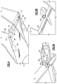
Figure 1 shows anaircraft body 20 having afuselage 22 andengines 24 mounted beneathwings 26. Theaircraft body 20 is a so-called "double-bubble" aircraft body.Rear stabilizers 28 lead to atail 30. Afuselage area 32 on top of the aircraft just forward of thetail 30 is relatively wide and boundary layer air across the wide fuselage raises drag issues. As such, in this disclosure, anair intake 34 leads to a cross flow fan to energize this boundary layer air. -
Figure 2 is a cross-sectional view along line 2-2 ofFigure 1 . The fuselage is not generally cylindrical in shape. This differs from the prior art conventional tube plus wing aircraft in which the fuselage is basically a cylindrical tube. The noncylindrical fuselage has a horizontal width significantly greater than its vertical height. This configuration may be achieved with a double bubble, which is essentially two cylinders blended together in the horizontal direction, or more generally any elongated or elliptical cross section that has width to height ratio significantly greater than unity. In embodiments, the ratio is greater than or equal to about 1.5 The flattened non-cylindrical fuselage shape has several potential advantages. It has less external wetted surface area for a given number of passengers compared to the cylindrical cross section, thus lowering aerodynamic drag. The flattened fuselage shape may be able to carry some lift, thus reducing the amount of lift required from the wings and the associated wing area. A further advantage that pertains to the present invention is that the flattened fuselage may close out at the back end to a flat beavertail shape with a trailing edge of finite width. The fuselage boundary layer may then be ingested into a high aspect ratio rectangular "mail slot" inlet arranged near the trailing edge of the beavertail between thevertical stabilizers 28. As shown, the fuselage in thearea 32 is not generally cylindrical in cross-section, as in the case in standard aircraft today. Rather, there are opposedsemicircular portions 36 separated by a generallystraight area 40. Thus, there are more circular sides and less curvedcentral areas 40. As mentioned, this results in a wide fuselage and drag issues being raised. -
Figure 3 shows details of theintake 34. As shown, a top 42 of the fuselage is spaced above afan 44. The fan is a transverse axis fan, also known as a crossflow fan.Fan 44 will drive the boundary layer air mentioned above to anoutlet 45 rearward of the aircraft such that the drag issues mentioned above are reduced. -
Figure 4 shows thefan 44 being driven byelectric motors 48.Motors 48drive shafts 46 that drive thefan 44 through bevel gears 47. Due to the bevel gears 47, themotors 48 can be positioned off axis relative to thefan 44, and such that thefan 44 is able to remove the boundary layer air across the majority of the width of thefuselage section 32. That is, themotors 48 drive axial ends offan rotor 44. While two electric motors are illustrated, it may be that only a single motor is necessary. -
Figure 5A shows an alternative wherein afan rotor 52 is driven by a smallgas turbine engine 54. A turbine drives agear 56 to, in turn, drive thefan rotor 52 through a bevel gear arrangement. Anair scoop 58 has aninlet 60 to bring air to thegas turbine engine 54. - As shown in
Figure 5B , theair inlet 60 and theengine 54 may be mounted in an axially intermediate location to drive thefan rotor 52. - The
gas turbine engine 54 may also be utilized as an auxiliary power unit (APU) to provide power and other functions associated with the aircraft. -
Figure 6 shows an alternative embodiment wherein theair intake 64 and also the small gas turbine engine (not specifically illustrated) is mounted within thestabilizer 62. Such a location may also be utilized for the electric motor embodiment ofFigure 4 . - The cross-flow fan across these embodiments will provide propulsion. Still, the bulk of the propulsion for the aircraft will come from the main gas turbine engines. In embodiments, the cross-flow fan may provide 10-25% of the overall propulsion provided in combination with the main gas turbine engines.
- Stated another way, there is a combined propulsion provided by the tail mounted fan rotor and the main gas turbine engines in combination. The fan rotor provides greater than or equal to about 10% and less than or equal to about 25% of the total propulsion.
- Although an embodiment of this invention has been disclosed, a worker of ordinary skill in this art would recognize that certain modifications would come within the scope of this invention. For that reason, the following claims should be studied to determine the true scope and content of this invention.
Claims (12)
- A cross flow fan (44) configured to be incorporated into an aircraft fuselage (22) comprising:an ingestion fan rotor (52) configured to be positioned in a tail section of the aircraft fuselage (22) to reduce boundary layer air from a top surface (32) of the fuselage (22) and to drive the air away from the top surface (32); anda drive arrangement for said ingestion fan rotor (52).
- The cross flow fan (44) as set forth in claim 1, wherein said drive arrangement drives said ingestion fan rotor (52) through a bevel gear (47; 56).
- The cross flow fan (44) as set forth in claim 1 or 2, wherein said drive arrangement is positioned at at least one axial end of the ingestion fan rotor (52).
- The cross flow fan (44) as set forth in claim 1 or 2, wherein said drive arrangement is positioned at an axially intermediate location on said ingestion fan rotor (52).
- The cross flow fan (44) as set forth in any preceding claim, wherein said drive arrangement incorporates at least one electric motor (48).
- The cross flow fan (44) as set forth in claim 5, wherein at least two electric motors (48) drive said ingestion fan rotor (52).
- The cross flow fan (44) as set forth in any of claims 1 to 4, wherein said drive arrangement includes a gas turbine engine (54).
- An aircraft comprising:an aircraft fuselage (22) having a relatively wide cross-sectional area at a location adjacent to and forward of a tail (30);main gas turbine engines (24) for driving the aircraft mounted at a location remote from said relatively wide portion of said fuselage (22); andthe cross flow fan (44) of any of claims 1 to 6, wherein said ingestion fan rotor (52) is positioned at said wide cross-sectional area.
- The aircraft as set forth in claim 8, wherein said drive arrangement includes an ingestion gas turbine engine (54).
- The aircraft as set forth in claim 8 or 9, further comprising rear stabilizers (28) extending upwardly from the fuselage (22) and connected to the tail (30), wherein said drive arrangement is mounted in at least one of said stabilizers (28).
- The aircraft as set forth in claim 8, 9 or 10, wherein there is a combined propulsion provided by said ingestion fan rotor (52) and said main gas turbine engines (24) in combination, and said ingestion fan rotor (52) provides greater than or equal to 10% and less than or equal to 25% of the total propulsion.
- The aircraft as set forth in as of claims 8 to 11, wherein said relatively wide cross-section area has a width to height ratio greater than or equal to about 1.5.
Applications Claiming Priority (1)
| Application Number | Priority Date | Filing Date | Title |
|---|---|---|---|
| US15/874,335 US10472081B2 (en) | 2016-03-17 | 2018-01-18 | Cross flow fan for wide aircraft fuselage |
Publications (2)
| Publication Number | Publication Date |
|---|---|
| EP3514057A1 true EP3514057A1 (en) | 2019-07-24 |
| EP3514057B1 EP3514057B1 (en) | 2023-03-08 |
Family
ID=62240414
Family Applications (1)
| Application Number | Title | Priority Date | Filing Date |
|---|---|---|---|
| EP19152397.6A Active EP3514057B1 (en) | 2018-01-18 | 2019-01-17 | Cross flow fan for wide aircraft fuselage |
Country Status (2)
| Country | Link |
|---|---|
| US (1) | US10472081B2 (en) |
| EP (1) | EP3514057B1 (en) |
Families Citing this family (5)
| Publication number | Priority date | Publication date | Assignee | Title |
|---|---|---|---|---|
| JP2020121683A (en) * | 2019-01-31 | 2020-08-13 | 三菱重工業株式会社 | Fluid control device and aircraft |
| US11338901B2 (en) | 2019-04-26 | 2022-05-24 | Rolls-Royce Corporation | Nacelle for a boundary layer ingestion propulsor |
| JP7346165B2 (en) | 2019-08-29 | 2023-09-19 | 三菱重工業株式会社 | Crossflow fan, lift generator equipped with the same, and aircraft equipped with the same |
| US12338007B2 (en) * | 2021-01-11 | 2025-06-24 | Cameron Carnegie | Circuit based vehicle |
| US11414182B1 (en) * | 2021-01-11 | 2022-08-16 | Cameron Carnegie | Circuit based unmanned aerial vehicle |
Citations (6)
| Publication number | Priority date | Publication date | Assignee | Title |
|---|---|---|---|---|
| US3334699A (en) * | 1963-12-11 | 1967-08-08 | Hovercraft Dev Ltd | Gas-cushion supported vehicles with drag inhibiting means |
| WO2006116072A1 (en) * | 2005-04-21 | 2006-11-02 | Syracuse University | Cross-flow fan propulsion system |
| US20120111994A1 (en) * | 2010-01-15 | 2012-05-10 | Propulsive Wing, LLC | Cross-flow fan propulsion system |
| US20140048657A1 (en) * | 2012-08-14 | 2014-02-20 | Yan-Liang Lin | Cross flow fan flying device |
| US20160009387A1 (en) * | 2014-04-18 | 2016-01-14 | Propulsive Wing, LLC | Hybrid Axial/Cross-Flow Fan Multi-Rotor Aerial Vehicle |
| EP3219606A1 (en) * | 2016-03-17 | 2017-09-20 | United Technologies Corporation | Cross flow fan with exit guide vanes |
Family Cites Families (9)
| Publication number | Priority date | Publication date | Assignee | Title |
|---|---|---|---|---|
| FR2932266B1 (en) | 2008-06-05 | 2010-07-30 | Airbus France | METHOD FOR PREDICTING THE DYNAMIC BEHAVIOR OF A STRUCTURE OF AN AIRCRAFT |
| US8157520B2 (en) | 2008-12-12 | 2012-04-17 | Kolacny Gordon S | Fan, airfoil and vehicle propulsion systems |
| FR2943039B1 (en) * | 2009-03-12 | 2012-09-28 | Airbus France | PLANE TANK-TAIL AND REVERSE ENGINE. |
| US8899520B2 (en) | 2009-05-24 | 2014-12-02 | The Boeing Company | Mid-wing airplane |
| US8746616B2 (en) | 2011-10-19 | 2014-06-10 | The Boeing Company | Mid-wing multi-deck airplane |
| US8807916B2 (en) | 2012-09-27 | 2014-08-19 | United Technologies Corporation | Method for setting a gear ratio of a fan drive gear system of a gas turbine engine |
| US8753065B2 (en) | 2012-09-27 | 2014-06-17 | United Technologies Corporation | Method for setting a gear ratio of a fan drive gear system of a gas turbine engine |
| US8678743B1 (en) | 2013-02-04 | 2014-03-25 | United Technologies Corporation | Method for setting a gear ratio of a fan drive gear system of a gas turbine engine |
| SE541609C2 (en) | 2013-06-25 | 2019-11-12 | Foersvarets Materielverk | Propulsion system for aircraft |
-
2018
- 2018-01-18 US US15/874,335 patent/US10472081B2/en active Active
-
2019
- 2019-01-17 EP EP19152397.6A patent/EP3514057B1/en active Active
Patent Citations (6)
| Publication number | Priority date | Publication date | Assignee | Title |
|---|---|---|---|---|
| US3334699A (en) * | 1963-12-11 | 1967-08-08 | Hovercraft Dev Ltd | Gas-cushion supported vehicles with drag inhibiting means |
| WO2006116072A1 (en) * | 2005-04-21 | 2006-11-02 | Syracuse University | Cross-flow fan propulsion system |
| US20120111994A1 (en) * | 2010-01-15 | 2012-05-10 | Propulsive Wing, LLC | Cross-flow fan propulsion system |
| US20140048657A1 (en) * | 2012-08-14 | 2014-02-20 | Yan-Liang Lin | Cross flow fan flying device |
| US20160009387A1 (en) * | 2014-04-18 | 2016-01-14 | Propulsive Wing, LLC | Hybrid Axial/Cross-Flow Fan Multi-Rotor Aerial Vehicle |
| EP3219606A1 (en) * | 2016-03-17 | 2017-09-20 | United Technologies Corporation | Cross flow fan with exit guide vanes |
Also Published As
| Publication number | Publication date |
|---|---|
| EP3514057B1 (en) | 2023-03-08 |
| US20180155045A1 (en) | 2018-06-07 |
| US10472081B2 (en) | 2019-11-12 |
Similar Documents
| Publication | Publication Date | Title |
|---|---|---|
| EP3514057B1 (en) | Cross flow fan for wide aircraft fuselage | |
| CN104670503B (en) | Aircraft | |
| EP3219606B1 (en) | Cross flow fan with exit guide vanes | |
| EP3216698B1 (en) | Propulsion system for an aircraft | |
| US10246197B2 (en) | Aircraft | |
| EP0084686B2 (en) | Improved aircraft | |
| US20060022084A1 (en) | Convertible aircraft provided with two tilt fans on either side of the fuselage, and with a non-tilting fan inserted in the fuselage | |
| EP3406519B1 (en) | Dedicated fans for boundary layer ingestion | |
| GB2542184A (en) | Aircraft comprising a boundary layer ingesting propulsor | |
| US11338927B2 (en) | Forward swept wing aircraft with boundary layer ingestion and distributed electrical propulsion system | |
| EP4155210B1 (en) | Aircraft with a combustion engine having an exhaust ahead of its air intake | |
| US2517524A (en) | Boundary layer control | |
| US12466548B2 (en) | Aircraft vertical stabilizer with air system | |
| US10814955B2 (en) | Aircraft having an AFT engine | |
| US3253808A (en) | Aircraft with boundary layer control | |
| US12202602B2 (en) | Fluid systems having a variable configuration | |
| US3159362A (en) | Lifting and propulsion means for aircraft | |
| EP3912904B1 (en) | Systems and methods for aircraft wing plug | |
| US12503219B2 (en) | Aeronautical propulsion system having electric fans | |
| US2964267A (en) | Aircraft engine fuel systems | |
| WO2021083821A1 (en) | Leading edge slat |
Legal Events
| Date | Code | Title | Description |
|---|---|---|---|
| PUAI | Public reference made under article 153(3) epc to a published international application that has entered the european phase |
Free format text: ORIGINAL CODE: 0009012 |
|
| STAA | Information on the status of an ep patent application or granted ep patent |
Free format text: STATUS: THE APPLICATION HAS BEEN PUBLISHED |
|
| AK | Designated contracting states |
Kind code of ref document: A1 Designated state(s): AL AT BE BG CH CY CZ DE DK EE ES FI FR GB GR HR HU IE IS IT LI LT LU LV MC MK MT NL NO PL PT RO RS SE SI SK SM TR |
|
| AX | Request for extension of the european patent |
Extension state: BA ME |
|
| STAA | Information on the status of an ep patent application or granted ep patent |
Free format text: STATUS: REQUEST FOR EXAMINATION WAS MADE |
|
| 17P | Request for examination filed |
Effective date: 20200124 |
|
| RBV | Designated contracting states (corrected) |
Designated state(s): AL AT BE BG CH CY CZ DE DK EE ES FI FR GB GR HR HU IE IS IT LI LT LU LV MC MK MT NL NO PL PT RO RS SE SI SK SM TR |
|
| STAA | Information on the status of an ep patent application or granted ep patent |
Free format text: STATUS: EXAMINATION IS IN PROGRESS |
|
| 17Q | First examination report despatched |
Effective date: 20200616 |
|
| RAP1 | Party data changed (applicant data changed or rights of an application transferred) |
Owner name: RAYTHEON TECHNOLOGIES CORPORATION |
|
| GRAP | Despatch of communication of intention to grant a patent |
Free format text: ORIGINAL CODE: EPIDOSNIGR1 |
|
| STAA | Information on the status of an ep patent application or granted ep patent |
Free format text: STATUS: GRANT OF PATENT IS INTENDED |
|
| INTG | Intention to grant announced |
Effective date: 20220912 |
|
| GRAS | Grant fee paid |
Free format text: ORIGINAL CODE: EPIDOSNIGR3 |
|
| GRAA | (expected) grant |
Free format text: ORIGINAL CODE: 0009210 |
|
| STAA | Information on the status of an ep patent application or granted ep patent |
Free format text: STATUS: THE PATENT HAS BEEN GRANTED |
|
| AK | Designated contracting states |
Kind code of ref document: B1 Designated state(s): AL AT BE BG CH CY CZ DE DK EE ES FI FR GB GR HR HU IE IS IT LI LT LU LV MC MK MT NL NO PL PT RO RS SE SI SK SM TR |
|
| REG | Reference to a national code |
Ref country code: CH Ref legal event code: EP Ref country code: AT Ref legal event code: REF Ref document number: 1552431 Country of ref document: AT Kind code of ref document: T Effective date: 20230315 |
|
| REG | Reference to a national code |
Ref country code: DE Ref legal event code: R096 Ref document number: 602019026038 Country of ref document: DE |
|
| REG | Reference to a national code |
Ref country code: IE Ref legal event code: FG4D |
|
| REG | Reference to a national code |
Ref country code: LT Ref legal event code: MG9D |
|
| P01 | Opt-out of the competence of the unified patent court (upc) registered |
Effective date: 20230521 |
|
| REG | Reference to a national code |
Ref country code: NL Ref legal event code: MP Effective date: 20230308 |
|
| PG25 | Lapsed in a contracting state [announced via postgrant information from national office to epo] |
Ref country code: RS Free format text: LAPSE BECAUSE OF FAILURE TO SUBMIT A TRANSLATION OF THE DESCRIPTION OR TO PAY THE FEE WITHIN THE PRESCRIBED TIME-LIMIT Effective date: 20230308 Ref country code: NO Free format text: LAPSE BECAUSE OF FAILURE TO SUBMIT A TRANSLATION OF THE DESCRIPTION OR TO PAY THE FEE WITHIN THE PRESCRIBED TIME-LIMIT Effective date: 20230608 Ref country code: LV Free format text: LAPSE BECAUSE OF FAILURE TO SUBMIT A TRANSLATION OF THE DESCRIPTION OR TO PAY THE FEE WITHIN THE PRESCRIBED TIME-LIMIT Effective date: 20230308 Ref country code: LT Free format text: LAPSE BECAUSE OF FAILURE TO SUBMIT A TRANSLATION OF THE DESCRIPTION OR TO PAY THE FEE WITHIN THE PRESCRIBED TIME-LIMIT Effective date: 20230308 Ref country code: HR Free format text: LAPSE BECAUSE OF FAILURE TO SUBMIT A TRANSLATION OF THE DESCRIPTION OR TO PAY THE FEE WITHIN THE PRESCRIBED TIME-LIMIT Effective date: 20230308 Ref country code: ES Free format text: LAPSE BECAUSE OF FAILURE TO SUBMIT A TRANSLATION OF THE DESCRIPTION OR TO PAY THE FEE WITHIN THE PRESCRIBED TIME-LIMIT Effective date: 20230308 |
|
| REG | Reference to a national code |
Ref country code: AT Ref legal event code: MK05 Ref document number: 1552431 Country of ref document: AT Kind code of ref document: T Effective date: 20230308 |
|
| PG25 | Lapsed in a contracting state [announced via postgrant information from national office to epo] |
Ref country code: SE Free format text: LAPSE BECAUSE OF FAILURE TO SUBMIT A TRANSLATION OF THE DESCRIPTION OR TO PAY THE FEE WITHIN THE PRESCRIBED TIME-LIMIT Effective date: 20230308 Ref country code: NL Free format text: LAPSE BECAUSE OF FAILURE TO SUBMIT A TRANSLATION OF THE DESCRIPTION OR TO PAY THE FEE WITHIN THE PRESCRIBED TIME-LIMIT Effective date: 20230308 Ref country code: GR Free format text: LAPSE BECAUSE OF FAILURE TO SUBMIT A TRANSLATION OF THE DESCRIPTION OR TO PAY THE FEE WITHIN THE PRESCRIBED TIME-LIMIT Effective date: 20230609 Ref country code: FI Free format text: LAPSE BECAUSE OF FAILURE TO SUBMIT A TRANSLATION OF THE DESCRIPTION OR TO PAY THE FEE WITHIN THE PRESCRIBED TIME-LIMIT Effective date: 20230308 |
|
| PG25 | Lapsed in a contracting state [announced via postgrant information from national office to epo] |
Ref country code: SM Free format text: LAPSE BECAUSE OF FAILURE TO SUBMIT A TRANSLATION OF THE DESCRIPTION OR TO PAY THE FEE WITHIN THE PRESCRIBED TIME-LIMIT Effective date: 20230308 Ref country code: RO Free format text: LAPSE BECAUSE OF FAILURE TO SUBMIT A TRANSLATION OF THE DESCRIPTION OR TO PAY THE FEE WITHIN THE PRESCRIBED TIME-LIMIT Effective date: 20230308 Ref country code: PT Free format text: LAPSE BECAUSE OF FAILURE TO SUBMIT A TRANSLATION OF THE DESCRIPTION OR TO PAY THE FEE WITHIN THE PRESCRIBED TIME-LIMIT Effective date: 20230710 Ref country code: EE Free format text: LAPSE BECAUSE OF FAILURE TO SUBMIT A TRANSLATION OF THE DESCRIPTION OR TO PAY THE FEE WITHIN THE PRESCRIBED TIME-LIMIT Effective date: 20230308 Ref country code: CZ Free format text: LAPSE BECAUSE OF FAILURE TO SUBMIT A TRANSLATION OF THE DESCRIPTION OR TO PAY THE FEE WITHIN THE PRESCRIBED TIME-LIMIT Effective date: 20230308 Ref country code: AT Free format text: LAPSE BECAUSE OF FAILURE TO SUBMIT A TRANSLATION OF THE DESCRIPTION OR TO PAY THE FEE WITHIN THE PRESCRIBED TIME-LIMIT Effective date: 20230308 |
|
| RAP4 | Party data changed (patent owner data changed or rights of a patent transferred) |
Owner name: RTX CORPORATION |
|
| PG25 | Lapsed in a contracting state [announced via postgrant information from national office to epo] |
Ref country code: SK Free format text: LAPSE BECAUSE OF FAILURE TO SUBMIT A TRANSLATION OF THE DESCRIPTION OR TO PAY THE FEE WITHIN THE PRESCRIBED TIME-LIMIT Effective date: 20230308 Ref country code: PL Free format text: LAPSE BECAUSE OF FAILURE TO SUBMIT A TRANSLATION OF THE DESCRIPTION OR TO PAY THE FEE WITHIN THE PRESCRIBED TIME-LIMIT Effective date: 20230308 Ref country code: IS Free format text: LAPSE BECAUSE OF FAILURE TO SUBMIT A TRANSLATION OF THE DESCRIPTION OR TO PAY THE FEE WITHIN THE PRESCRIBED TIME-LIMIT Effective date: 20230708 |
|
| REG | Reference to a national code |
Ref country code: DE Ref legal event code: R097 Ref document number: 602019026038 Country of ref document: DE |
|
| PLBE | No opposition filed within time limit |
Free format text: ORIGINAL CODE: 0009261 |
|
| STAA | Information on the status of an ep patent application or granted ep patent |
Free format text: STATUS: NO OPPOSITION FILED WITHIN TIME LIMIT |
|
| PG25 | Lapsed in a contracting state [announced via postgrant information from national office to epo] |
Ref country code: SI Free format text: LAPSE BECAUSE OF FAILURE TO SUBMIT A TRANSLATION OF THE DESCRIPTION OR TO PAY THE FEE WITHIN THE PRESCRIBED TIME-LIMIT Effective date: 20230308 Ref country code: DK Free format text: LAPSE BECAUSE OF FAILURE TO SUBMIT A TRANSLATION OF THE DESCRIPTION OR TO PAY THE FEE WITHIN THE PRESCRIBED TIME-LIMIT Effective date: 20230308 |
|
| 26N | No opposition filed |
Effective date: 20231211 |
|
| PG25 | Lapsed in a contracting state [announced via postgrant information from national office to epo] |
Ref country code: IT Free format text: LAPSE BECAUSE OF FAILURE TO SUBMIT A TRANSLATION OF THE DESCRIPTION OR TO PAY THE FEE WITHIN THE PRESCRIBED TIME-LIMIT Effective date: 20230308 |
|
| PG25 | Lapsed in a contracting state [announced via postgrant information from national office to epo] |
Ref country code: MC Free format text: LAPSE BECAUSE OF FAILURE TO SUBMIT A TRANSLATION OF THE DESCRIPTION OR TO PAY THE FEE WITHIN THE PRESCRIBED TIME-LIMIT Effective date: 20230308 |
|
| PG25 | Lapsed in a contracting state [announced via postgrant information from national office to epo] |
Ref country code: MC Free format text: LAPSE BECAUSE OF FAILURE TO SUBMIT A TRANSLATION OF THE DESCRIPTION OR TO PAY THE FEE WITHIN THE PRESCRIBED TIME-LIMIT Effective date: 20230308 |
|
| REG | Reference to a national code |
Ref country code: CH Ref legal event code: PL |
|
| PG25 | Lapsed in a contracting state [announced via postgrant information from national office to epo] |
Ref country code: LU Free format text: LAPSE BECAUSE OF NON-PAYMENT OF DUE FEES Effective date: 20240117 |
|
| PG25 | Lapsed in a contracting state [announced via postgrant information from national office to epo] |
Ref country code: LU Free format text: LAPSE BECAUSE OF NON-PAYMENT OF DUE FEES Effective date: 20240117 |
|
| PG25 | Lapsed in a contracting state [announced via postgrant information from national office to epo] |
Ref country code: BE Free format text: LAPSE BECAUSE OF NON-PAYMENT OF DUE FEES Effective date: 20240131 |
|
| PG25 | Lapsed in a contracting state [announced via postgrant information from national office to epo] |
Ref country code: CH Free format text: LAPSE BECAUSE OF NON-PAYMENT OF DUE FEES Effective date: 20240131 |
|
| PG25 | Lapsed in a contracting state [announced via postgrant information from national office to epo] |
Ref country code: CH Free format text: LAPSE BECAUSE OF NON-PAYMENT OF DUE FEES Effective date: 20240131 Ref country code: BE Free format text: LAPSE BECAUSE OF NON-PAYMENT OF DUE FEES Effective date: 20240131 |
|
| REG | Reference to a national code |
Ref country code: BE Ref legal event code: MM Effective date: 20240131 |
|
| PG25 | Lapsed in a contracting state [announced via postgrant information from national office to epo] |
Ref country code: BG Free format text: LAPSE BECAUSE OF FAILURE TO SUBMIT A TRANSLATION OF THE DESCRIPTION OR TO PAY THE FEE WITHIN THE PRESCRIBED TIME-LIMIT Effective date: 20230308 |
|
| PG25 | Lapsed in a contracting state [announced via postgrant information from national office to epo] |
Ref country code: BG Free format text: LAPSE BECAUSE OF FAILURE TO SUBMIT A TRANSLATION OF THE DESCRIPTION OR TO PAY THE FEE WITHIN THE PRESCRIBED TIME-LIMIT Effective date: 20230308 |
|
| PG25 | Lapsed in a contracting state [announced via postgrant information from national office to epo] |
Ref country code: IE Free format text: LAPSE BECAUSE OF NON-PAYMENT OF DUE FEES Effective date: 20240117 |
|
| PG25 | Lapsed in a contracting state [announced via postgrant information from national office to epo] |
Ref country code: IE Free format text: LAPSE BECAUSE OF NON-PAYMENT OF DUE FEES Effective date: 20240117 |
|
| PG25 | Lapsed in a contracting state [announced via postgrant information from national office to epo] |
Ref country code: CY Free format text: LAPSE BECAUSE OF FAILURE TO SUBMIT A TRANSLATION OF THE DESCRIPTION OR TO PAY THE FEE WITHIN THE PRESCRIBED TIME-LIMIT; INVALID AB INITIO Effective date: 20190117 |
|
| PG25 | Lapsed in a contracting state [announced via postgrant information from national office to epo] |
Ref country code: HU Free format text: LAPSE BECAUSE OF FAILURE TO SUBMIT A TRANSLATION OF THE DESCRIPTION OR TO PAY THE FEE WITHIN THE PRESCRIBED TIME-LIMIT; INVALID AB INITIO Effective date: 20190117 |
|
| REG | Reference to a national code |
Ref country code: DE Ref legal event code: R081 Ref document number: 602019026038 Country of ref document: DE Owner name: RTX CORPORATION (N.D.GES.D. STAATES DELAWARE),, US Free format text: FORMER OWNER: RAYTHEON TECHNOLOGIES CORPORATION, FARMINGTON, CT, US |
|
| PG25 | Lapsed in a contracting state [announced via postgrant information from national office to epo] |
Ref country code: TR Free format text: LAPSE BECAUSE OF FAILURE TO SUBMIT A TRANSLATION OF THE DESCRIPTION OR TO PAY THE FEE WITHIN THE PRESCRIBED TIME-LIMIT Effective date: 20230308 |
|
| PGFP | Annual fee paid to national office [announced via postgrant information from national office to epo] |
Ref country code: GB Payment date: 20251220 Year of fee payment: 8 |
|
| PGFP | Annual fee paid to national office [announced via postgrant information from national office to epo] |
Ref country code: FR Payment date: 20251217 Year of fee payment: 8 |
|
| PGFP | Annual fee paid to national office [announced via postgrant information from national office to epo] |
Ref country code: DE Payment date: 20251217 Year of fee payment: 8 |