EP3514019A1 - Side airbag device - Google Patents
Side airbag device Download PDFInfo
- Publication number
- EP3514019A1 EP3514019A1 EP17850612.7A EP17850612A EP3514019A1 EP 3514019 A1 EP3514019 A1 EP 3514019A1 EP 17850612 A EP17850612 A EP 17850612A EP 3514019 A1 EP3514019 A1 EP 3514019A1
- Authority
- EP
- European Patent Office
- Prior art keywords
- cushion
- baffle
- distance
- occupant
- intermediate region
- Prior art date
- Legal status (The legal status is an assumption and is not a legal conclusion. Google has not performed a legal analysis and makes no representation as to the accuracy of the status listed.)
- Granted
Links
Images
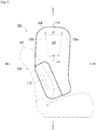


Classifications
-
- B—PERFORMING OPERATIONS; TRANSPORTING
- B60—VEHICLES IN GENERAL
- B60R—VEHICLES, VEHICLE FITTINGS, OR VEHICLE PARTS, NOT OTHERWISE PROVIDED FOR
- B60R21/00—Arrangements or fittings on vehicles for protecting or preventing injuries to occupants or pedestrians in case of accidents or other traffic risks
- B60R21/02—Occupant safety arrangements or fittings, e.g. crash pads
- B60R21/16—Inflatable occupant restraints or confinements designed to inflate upon impact or impending impact, e.g. air bags
- B60R21/23—Inflatable members
- B60R21/231—Inflatable members characterised by their shape, construction or spatial configuration
- B60R21/23138—Inflatable members characterised by their shape, construction or spatial configuration specially adapted for side protection
-
- B—PERFORMING OPERATIONS; TRANSPORTING
- B60—VEHICLES IN GENERAL
- B60R—VEHICLES, VEHICLE FITTINGS, OR VEHICLE PARTS, NOT OTHERWISE PROVIDED FOR
- B60R21/00—Arrangements or fittings on vehicles for protecting or preventing injuries to occupants or pedestrians in case of accidents or other traffic risks
- B60R2021/003—Arrangements or fittings on vehicles for protecting or preventing injuries to occupants or pedestrians in case of accidents or other traffic risks characterised by occupant or pedestian
- B60R2021/0039—Body parts of the occupant or pedestrian affected by the accident
- B60R2021/0048—Head
-
- B—PERFORMING OPERATIONS; TRANSPORTING
- B60—VEHICLES IN GENERAL
- B60R—VEHICLES, VEHICLE FITTINGS, OR VEHICLE PARTS, NOT OTHERWISE PROVIDED FOR
- B60R21/00—Arrangements or fittings on vehicles for protecting or preventing injuries to occupants or pedestrians in case of accidents or other traffic risks
- B60R21/02—Occupant safety arrangements or fittings, e.g. crash pads
- B60R21/16—Inflatable occupant restraints or confinements designed to inflate upon impact or impending impact, e.g. air bags
- B60R21/23—Inflatable members
- B60R21/231—Inflatable members characterised by their shape, construction or spatial configuration
- B60R21/23138—Inflatable members characterised by their shape, construction or spatial configuration specially adapted for side protection
- B60R2021/23146—Inflatable members characterised by their shape, construction or spatial configuration specially adapted for side protection seat mounted
Definitions
- the present invention relates to a side airbag device for restraining an occupant at a vehicle seat from the side when an impact has occurred in a vehicle, for example.
- An airbag is a safety device that operates in an emergency, such as collision of vehicles, and is expanded and deployed by gas pressure to receive and protect an occupant.
- An airbag is a safety device that operates in an emergency, such as collision of vehicles, and is expanded and deployed by gas pressure to receive and protect an occupant.
- airbags There are various kinds of airbags depending on installation positions and purposes.
- a front airbag device is provided at the center of a steering wheel in order to protect a driver from collision in the longitudinal direction.
- a curtain airbag device to be expanded and deployed along a side window from the vicinity of a ceiling of a wall portion, and a side airbag device to be expanded and deployed toward the side of an occupant from a side portion of a seat are provided.
- a side airbag device in Patent Literature 1 side walls on both sides of an air bag in the vehicle width direction are sewn to form a pair of front and rear V seams. At lower ends of the pair of front and rear V seams, a pair of circular seams continuous thereto are formed. According to Patent Literature 1, these seams are functioned as an expansion limiting structure such that the head of a large occupant is protected by a region between the V seams and the head of a small occupant is protected by a region between the circular seams.
- Patent Literature 1 has made a study of partitioning of the inside of the cushion by tether. However, if tether extending in the vehicle longitudinal direction is used as in Patent Literature 1, the positions of a region for protecting the head of a small occupant in the vehicle longitudinal direction and the height direction are extremely limited.
- Patent Literature 1 also discloses a configuration in which the inside of a cushion is partitioned by vertical tether extending in the vehicle vertical direction. Although Patent Literature 1 mentions the arrangement of the vertical tether in side view, Patent Literature 1 does not disclose the shape of the vertical tether at all. Thus, there is room for further improvement in order to support various positions of the head that changes depending on the difference in physical size of occupants.
- the present invention has been made in view of the above, and it is an object thereof to provide a side airbag device capable of appropriately restraining, for each occupant, the head of the occupant that variously changes in position depending on the physical size of the occupant.
- a representative configuration of a side airbag device resides in a side airbag device to be expanded and deployed to a front side in a vehicle from a side part of a seat of the vehicle, the side airbag device including: a cushion provided by forming a base cloth into a bag shape; an inflator for supplying gas to the cushion to expand and deploy the cushion; and a front baffle and a rear baffle disposed inside the cushion at a distance therebetween in a vehicle longitudinal direction and spread in a vehicle width direction, in which the front baffle and the rear baffle are each made of cloth having an inverted trapezoidal shape in which an upper side is longer than a lower side, and are bonded to inner surfaces of the base cloth at both lateral sides, a distance between the upper sides of the front baffle and the rear baffle is larger than a distance between the lower sides thereof, and the cushion is configured to restrain a head of an occupant by an intermediate region between the front baffle and the rear
- a chamber of the intermediate region surrounded by the front baffle, the rear baffle, and the base cloth of the cushion between the baffles may have an inverted frustum shape when the cushion is expanded and deployed.
- the front baffle and the rear baffle are inverted trapezoids.
- the thickness of the intermediate region in the vehicle width direction between the front baffle and the rear baffle can be changed continuously from the top to the bottom.
- An upper part of the intermediate region has the largest thickness in the vehicle width direction in the intermediate region. Consequently, the heavy head of a large occupant can be reliably restrained with a sufficient thickness.
- the weight of the head of a small occupant is small, and hence the thickness of the cushion for restraining the head may be smaller than that for a large occupant.
- the thickness of the cushion becomes smaller toward the bottom. Consequently, the head of a small occupant is restrained at a lower part of the intermediate region, that is, a thin portion, thereby alleviating the impact on the head.
- the thickness of the intermediate region in the vehicle width direction becomes continuously smaller toward the bottom. Consequently, the head of an occupant that variously changes in position depending on the physical size of the occupant can be appropriately restrained for each occupant.
- both lateral sides of the front baffle and the rear baffle are bonded to inner surfaces of the base cloth such that the distance between upper sides is larger than the distance between lower sides.
- the front baffle and the rear baffle are bonded to the base cloth so as to have a V shape in side view. In this manner, when the cushion is expanded and developed, in the intermediate region, the curvature radius of the side surface of the cushion becomes larger from the top to the bottom.
- the curvature radius of the cushion at the upper part of the intermediate region is small.
- the contact area of the cushion with the head of a large occupant increases.
- the heavy head can be restrained with a wide area.
- the curvature radius of the cushion at the lower part of the intermediate region is large.
- the lower part of the intermediate region corresponds to the vicinity of the shoulders of a large occupant.
- the shoulder part protrudes in the vehicle width direction as compared with the head, and by restraining the shoulder by this part thinner than the upper part (protection region of head), the entire occupant can be received by the airbag without excessively protecting only the head or shoulder, which is preferred in view of balance of restraint.
- the contact area of the cushion with the head of a small occupant decreases.
- impact on the head of a small occupant from the cushion upon restraint can be alleviated as compared with a part on a large occupant, and hence even a small occupant can be appropriately protected and restrained.
- the inflator may be disposed inside a seat back at a position lower than the intermediate region.
- a distance from the upper side of the front baffle to a front edge of the cushion may be smaller than a distance from the lower side of the front baffle to the front edge of the cushion
- a distance from the upper side of the rear baffle to a rear edge of the cushion may be smaller than a distance from the lower side of the rear baffle to the rear edge of the cushion.
- gas channels that become narrower toward the top are formed between the two baffles and the front edge and the rear edge of the cushion, that is, on the outer side of the intermediate region.
- a wide opening of the intermediate region formed between the upper sides of the two baffles is disposed ahead of the tapered gas channels.
- the gas flows into the intermediate region from the upper wide opening more preferentially than the lower narrow opening.
- the upper part of the intermediate region is thicker than the lower part thereof and requires a larger amount of gas. The gas flows into the upper part preferentially, and hence the head of a large occupant can be more reliably restrained.
- a distance between an upper edge of the cushion and the upper side of the front baffle and a distance between the upper edge of the cushion and the upper side of the rear baffle may be smaller than the distance between the upper sides of the front baffle and the rear baffle.
- the present invention can provide a side airbag device capable of appropriately restraining, for each occupant, the head of the occupant that variously changes in position depending on the physical size of the occupant.
- Fig. 1 is a diagram exemplifying a side airbag device 100 according to an embodiment of the present invention.
- the side airbag device 100 and a right seat 102 of a vehicle to which the side airbag device 100 is applied are exemplified from the outer side in a vehicle width direction.
- the side airbag device 100 is configured such that a cushion 104 is expanded and deployed on the side of the seat 102.
- the cushion 104 is a bag-shaped site for receiving an occupant in an emergency, such as when an impact has occurred in the vehicle, and is expanded and deployed into a flat shape at the seat 102 on the vehicle center side (so-called far side). In this manner, upon side collision of the vehicle, the cushion 104 restricts the occupant from moving toward the center of the vehicle.
- the cushion 104 is formed into a bag shape by sawing and bonding a plurality of base cloths in an overlapping manner.
- the cushion 104 is housed in a housing (not shown) provided on the side of the seat back 106 while being wound or folded.
- the housed cushion 104 is covered with a seat cover from the top, and cannot be visually recognized from the outside.
- the cushion 104 cleaves the seat cover and is expanded and deployed to the side of the occupant, thereby restraining the occupant from the side.
- An inflator 110 is installed on the side of the seat back 106 together with the cushion 104.
- the inflator 110 is a gas production device, and supplies gas into the cushion 104 to expand and deploy the cushion 104 in response to an operation signal transmitted from the vehicle upon impact.
- the inflator 110 employed in the present embodiment is of a cylinder type, and is enclosed and installed in the cushion 104 such that the longitudinal direction of the inflator 110 is oriented in the vertical direction.
- the inflator 110 is fastened to a housing at the side of the seat back 106 by exposing stud bolts (not shown) integrated with the surface to the outside of the cushion 104 from the inner side.
- Types of inflators currently widespread include a type in which a gas generating agent is loaded and is combusted to generate gas, a type in which compression gas is loaded and gas is supplied without generating heat, and a hybrid type in which both combustion gas and compression gas are used.
- the inflator 110 any of the types can be used.
- the feature of the present embodiment resides in that two baffles, a front baffle 120a and a rear baffle 120b, are disposed inside the cushion 104.
- the front baffle 120a and the rear baffle 120b are disposed inside the cushion 104 at a distance from each other in the vehicle longitudinal direction and are spread in the vehicle width direction.
- an intermediate region 130 is formed between the front baffle 120a and the rear baffle 120b. As described later, the head of an occupant is restrained by the intermediate region 130.
- Fig. 2 is a front view of the front baffle 120a in Fig. 1 as seen from the front.
- Fig. 3 is a cross-sectional view of the side airbag device 100 in Fig. 1 taken along the line A-A.
- the front baffle 120a and the rear baffle 120b have the same shape, and hence the front baffle 120a is exemplified in Fig. 2 and Fig. 3 .
- the front baffle 120a and the rear baffle 120b may have different shapes.
- the front baffle 120a is made of cloth having an inverted trapezoidal shape in which an upper side 122 is longer than a lower side 124.
- lateral sides 126a and 126b (both lateral sides) of the front baffle 120a are bonded to inner surfaces 104a and 104b of a base cloth constituting the cushion 104.
- the present embodiment exemplifies the configuration in which the front baffle 120a is an isosceles trapezoid having the same length of both lateral sides, but does not exclude trapezoids other than the isosceles trapezoid.
- Fig. 1 is referred to again.
- the front baffle 120a and the rear baffle 120b are bonded to the cushion 104 (base cloth) such that the distance D1 between the upper sides is larger than the distance D2 between the lower sides.
- the front baffle 120a and the rear baffle 120b are disposed to have a V shape in side view.
- Fig. 4 is a perspective view of the intermediate region 130 observed from the above when the cushion 104 in Fig. 1 is expanded and deployed.
- Fig. 4 illustrates only the intermediate region 130, and the illustration of other regions is omitted.
- the front baffle 120a and the rear baffle 120b having an inverted trapezoidal shape are disposed with a distance therebetween in the vehicle longitudinal direction so as to have a V shape.
- all the four faces of the intermediate region 130 formed of the front baffle 120a, the rear baffle 120b, and the base cloth of the cushion 104 therebetween in Fig. 4 , inner surfaces 104a and 104b of the base cloth are illustrated) have an inverted trapezoidal shape.
- the intermediate region 130 after the cushion 104 is expanded and deployed that is, a chamber of the intermediate region 130, has an inverted frustum shape in which four faces are approximated to a quadratic prism or a column having an inverted trapezoidal shape (an inverted frustum shape in which a circular truncated cone or a truncated pyramid obtained by cutting an acute distal end is provided upside down.
- inverted frustum shape an inverted frustum shape in which a circular truncated cone or a truncated pyramid obtained by cutting an acute distal end is provided upside down.
- a chamber having an inverted frustum shape is formed by the front baffle 120a and the rear baffle 120b.
- gas can be caused to appropriately remain in a region (intermediate region 130) for restraining the head of an occupant as compared with the case where the front baffle 120a and the rear baffle 120b are not provided.
- Fig. 5 is a diagram exemplifying a restraint position of the head of an occupant in the intermediate region 130 in Fig. 4 .
- the side airbag device 100 restrains the head of an occupant in the intermediate region 130 between the front baffle 120a and the rear baffle 120b.
- a head H1 of a large occupant is restrained at an upper part of the intermediate region 130
- a head H3 of a small occupant is restrained at a lower part of the intermediate region 130
- a head H2 of an occupant having an intermediate physical size (hereinafter referred to as "medium occupant") is restrained at a center part of an intermediate position in the height direction of the intermediate region 130.
- Fig. 6 shows cross-sectional views of the cushion 104 in Fig. 5 .
- Fig. 6(a) is a cross-sectional view taken along the line B-B in Fig. 5
- Fig. 6(b) is a cross-sectional view taken along the line C-C in Fig. 1
- Fig. 6(c) is a cross-sectional view taken along the line D-D in Fig. 1 .
- Fig. 6(a) is a cross-sectional view of a position (upper part) at which the head H1 of a large occupant is restrained
- Fig. 6(a) is a cross-sectional view of a position (upper part) at which the head H1 of a large occupant is restrained
- Fig. 6(a) is a cross-sectional view of a position (upper part) at which the head H1 of a large occupant is restrained
- FIG. 6(b) is a cross-sectional view of a position (center part) at which the head H2 of a medium occupant is restrained
- Fig. 6(c) is a cross-sectional view of a position (lower part) at which the head H3 of a small occupant is restrained.
- the front baffle 120a and the rear baffle 120b have an inverted trapezoidal shape, and hence, as illustrated in Figs. 6(a) to 6(c) , the thickness of the intermediate region in the cushion 104 in the vehicle width direction becomes smaller from the top to the bottom in the order of "thickness T1 at upper part>thickness T2 at center part>thickness T3 at lower part".
- the thickness T1 at the upper part of the intermediate region 130 is the largest in the intermediate region.
- the weight of the head H3 of a small occupant is small.
- the head H3 of a small occupant can be sufficiently restrained with a thickness smaller than that for restraining the head H1 of a large occupant.
- the thickness of the cushion 104 is too large, there is a fear in that impact on the head H3 of an occupant when the head H3 is restrained by the cushion 104 may increase.
- the thickness T3 at the lower part of the intermediate region 130 is smaller than the thickness T1 at the upper part exemplified in Fig. 6(a) . In this manner, the head H3 of a small occupant can be restrained at the lower part of the intermediate region 130 while alleviating the impact.
- the thickness T2 has an intermediate value between the thickness at the upper part and the thickness at the lower part.
- the head H2 of a medium occupant can be appropriately restrained. Consequently, the side airbag device 100 in the present embodiment can appropriately and reliably restrain the head that changes in position and weight depending on the difference in physical size of the occupant in a wider range.
- the front baffle 120a and the rear baffle 120b are bonded to the cushion 104 (base cloth) such that the distance D1 between the upper sides 122 is larger than the distance D2 of the lower sides 124 (see Fig. 1 ).
- the curvature radius becomes larger from the top to the bottom in the order of "curvature radius r1 at upper part ⁇ curvature radius r2 at center part ⁇ curvature radius r3 at lower part" as illustrated in Fig. 6(a) to Fig. 6(c) .
- the curvature radius of the intermediate region 130 becomes larger to the bottom as described above is because the distance D1 between the upper sides 122 of the front baffle 120a and the rear baffle 120b is larger than the distance D2 between the lower sides 124. Specifically, the base cloth expands over a wide area at an upper part of the intermediate region 130 where the upper sides 122 of the front baffle 120a and the rear baffle 120b are separated away from each other by the wide distance D1. Thus, the curvature radius of the cushion 104 (base cloth) is small.
- the cushion 104 (base cloth) expands only over a narrow area at a lower part of the intermediate region 130 where the lower sides of the front baffle 120a and the rear baffle 120b are separated away from each other by the narrow distance D2.
- the curvature radius of the cushion 104 (base cloth) is large.
- the curvature radius has an intermediate value between the curvature radius at the upper part and the curvature radius at the lower part.
- the curvature radius r1 of the upper part of the intermediate region 130 is small, and hence the contact area between the head H1 of a large occupant and the cushion 104 increases.
- the heavy head H1 can be reliably restrained with a large area.
- the curvature radius r3 of the lower part of the intermediate region 130 is large, and hence the contact area between the head H3 of a small occupant and the cushion 104 decreases.
- the head H3 can be restrained while reducing impact during the restraint by the cushion 104.
- the contact area between the head H2 of a medium occupant and the cushion 104 is smaller than the upper part and larger than the lower part.
- the head H2 can be restrained with an appropriate area while alleviating impact during the restraint.
- Fig. 7 is a diagram for describing the flow of gas in the cushion 104 in Fig. 1 .
- the inflator 110 is disposed inside the seat back 106 at a position lower than the intermediate region 130.
- a distance D3 from the upper side 122 of the front baffle 120a to the front edge 104c of the cushion 104 is set to be smaller than a distance D4 from the lower side 124 of the front baffle 120a to the front edge of the cushion 104.
- a distance D5 from the upper side 122 of the rear baffle 120b to the rear edge 104d of the cushion 104 is set to be smaller than a distance D6 from the lower side 124 of the rear baffle 120b to the rear edge 104d of the cushion 104.
- gas channels that become narrower toward the top are formed on the front and rear sides of the intermediate region 130.
- the gas supplied from the inflator 110 flows into the intermediate region 130 from an opening between the lower sides 124 of the front baffle 120a and the rear baffle 120b and an opening between the upper sides 122 of the front baffle 120a and the rear baffle 120b.
- a wide opening of the intermediate region 130 formed between the upper sides 122 of the front baffle 120a and the rear baffle 120b is disposed ahead of the gas channels tapered upward.
- the gas flows into the upper wide opening of the intermediate region 130 more preferentially than the lower narrow opening.
- the gas can be caused to flow preferentially to the upper part of the intermediate region 130 thicker than the lower part thereof, that is, the upper part of the intermediate region 130 for which a large amount of gas is necessary for expansion and deployment. Consequently, the head H1 of a large occupant can be more reliably restrained at the upper part of the intermediate region 130.
- the distance D4 between the front baffle 120a and the front edge 104c of the cushion 104 and the distance D6 between the rear baffle 120b and the rear edge 104d of the cushion 104 be larger than the distance D2 between the lower sides 124 of the front baffle 120a and the rear baffle 120b. In this manner, the amount of gas that flows upward in the intermediate region 130 can be increased to cause the gas to flow to the upper part of the intermediate region 130 more efficiently.
- the distance D7 between the upper edge 104e of the cushion 104 and the upper sides 122 of the front baffle 120a and the rear baffle 120b is set to be smaller than the distance D1 between the upper sides 122 of the front baffle 120a and the rear baffle 120b. In this manner, gas that has flowed through the channels on the front and rear sides of the intermediate region 130 and been directed upward can be efficiently guided to the upper opening of the intermediate region 130.
- the present invention can be used for a side airbag device for restraining an occupant at a vehicle seat from the side when an impact has occurred in a vehicle, for example.
Landscapes
- Engineering & Computer Science (AREA)
- Mechanical Engineering (AREA)
- Air Bags (AREA)
Abstract
Description
- The present invention relates to a side airbag device for restraining an occupant at a vehicle seat from the side when an impact has occurred in a vehicle, for example.
- Most of recent vehicles are equipped with airbags as standard. An airbag is a safety device that operates in an emergency, such as collision of vehicles, and is expanded and deployed by gas pressure to receive and protect an occupant. There are various kinds of airbags depending on installation positions and purposes. For example, a front airbag device is provided at the center of a steering wheel in order to protect a driver from collision in the longitudinal direction. Further, to protect occupants from side collision and subsequent rollover, a curtain airbag device to be expanded and deployed along a side window from the vicinity of a ceiling of a wall portion, and a side airbag device to be expanded and deployed toward the side of an occupant from a side portion of a seat, are provided.
- The physical sizes of occupants who ride on vehicles vary from large occupants to small occupants. For example, in a side airbag device in Patent Literature 1, side walls on both sides of an air bag in the vehicle width direction are sewn to form a pair of front and rear V seams. At lower ends of the pair of front and rear V seams, a pair of circular seams continuous thereto are formed. According to Patent Literature 1, these seams are functioned as an expansion limiting structure such that the head of a large occupant is protected by a region between the V seams and the head of a small occupant is protected by a region between the circular seams.
- [PTL 1] Japanese Patent Application Publication No.
2016-252773 - However, in a configuration in which the inside of a cushion is partitioned by seams as disclosed in Patent Literature 1, an unsewn portion (portion not unsewn) is provided between the seams such that gas circulates. In this case, depending on how the force is applied upon expansion and deployment, it may be difficult to apply the force in a direction to open an unsewn portion between seams, and the gas cannot smoothly circulate. In particular, in Patent Literature 1, the gas can flow into an unsewn portion between two seams only from the bottom. Thus, there is a feat in that it may be more difficult to cause the gas to flow into the unsewn portion.
- It is conceivable to partition the inside of the cushion by tether (also called "baffle") rather than seams. Patent Literature 1 has made a study of partitioning of the inside of the cushion by tether. However, if tether extending in the vehicle longitudinal direction is used as in Patent Literature 1, the positions of a region for protecting the head of a small occupant in the vehicle longitudinal direction and the height direction are extremely limited.
- Patent Literature 1 also discloses a configuration in which the inside of a cushion is partitioned by vertical tether extending in the vehicle vertical direction. Although Patent Literature 1 mentions the arrangement of the vertical tether in side view, Patent Literature 1 does not disclose the shape of the vertical tether at all. Thus, there is room for further improvement in order to support various positions of the head that changes depending on the difference in physical size of occupants.
- The present invention has been made in view of the above, and it is an object thereof to provide a side airbag device capable of appropriately restraining, for each occupant, the head of the occupant that variously changes in position depending on the physical size of the occupant.
- In order to solve the above-mentioned problem, a representative configuration of a side airbag device according to the present invention resides in a side airbag device to be expanded and deployed to a front side in a vehicle from a side part of a seat of the vehicle, the side airbag device including: a cushion provided by forming a base cloth into a bag shape; an inflator for supplying gas to the cushion to expand and deploy the cushion; and a front baffle and a rear baffle disposed inside the cushion at a distance therebetween in a vehicle longitudinal direction and spread in a vehicle width direction, in which the front baffle and the rear baffle are each made of cloth having an inverted trapezoidal shape in which an upper side is longer than a lower side, and are bonded to inner surfaces of the base cloth at both lateral sides, a distance between the upper sides of the front baffle and the rear baffle is larger than a distance between the lower sides thereof, and the cushion is configured to restrain a head of an occupant by an intermediate region between the front baffle and the rear baffle when expanded and deployed.
- A chamber of the intermediate region surrounded by the front baffle, the rear baffle, and the base cloth of the cushion between the baffles may have an inverted frustum shape when the cushion is expanded and deployed.
- In the above-mentioned configuration, the front baffle and the rear baffle are inverted trapezoids. In this manner, the thickness of the intermediate region in the vehicle width direction between the front baffle and the rear baffle can be changed continuously from the top to the bottom. An upper part of the intermediate region has the largest thickness in the vehicle width direction in the intermediate region. Consequently, the heavy head of a large occupant can be reliably restrained with a sufficient thickness.
- The weight of the head of a small occupant is small, and hence the thickness of the cushion for restraining the head may be smaller than that for a large occupant. When restraining the head of a small occupant, if the thickness of the cushion is too large, impact on the head upon contact with the cushion may increase. Thus, according to the present invention, the thickness of the intermediate region becomes smaller toward the bottom. Consequently, the head of a small occupant is restrained at a lower part of the intermediate region, that is, a thin portion, thereby alleviating the impact on the head.
- As described above, the thickness of the intermediate region in the vehicle width direction becomes continuously smaller toward the bottom. Consequently, the head of an occupant that variously changes in position depending on the physical size of the occupant can be appropriately restrained for each occupant.
- Further, with the above-mentioned configuration, both lateral sides of the front baffle and the rear baffle are bonded to inner surfaces of the base cloth such that the distance between upper sides is larger than the distance between lower sides. Specifically, the front baffle and the rear baffle are bonded to the base cloth so as to have a V shape in side view. In this manner, when the cushion is expanded and developed, in the intermediate region, the curvature radius of the side surface of the cushion becomes larger from the top to the bottom.
- The curvature radius of the cushion at the upper part of the intermediate region is small. Thus, the contact area of the cushion with the head of a large occupant increases. Thus, the heavy head can be restrained with a wide area. The curvature radius of the cushion at the lower part of the intermediate region is large. The lower part of the intermediate region corresponds to the vicinity of the shoulders of a large occupant. The shoulder part protrudes in the vehicle width direction as compared with the head, and by restraining the shoulder by this part thinner than the upper part (protection region of head), the entire occupant can be received by the airbag without excessively protecting only the head or shoulder, which is preferred in view of balance of restraint. At the lower part of the intermediate region, the contact area of the cushion with the head of a small occupant decreases. Thus, impact on the head of a small occupant from the cushion upon restraint can be alleviated as compared with a part on a large occupant, and hence even a small occupant can be appropriately protected and restrained.
- The inflator may be disposed inside a seat back at a position lower than the intermediate region. In side view with the cushion expanded, a distance from the upper side of the front baffle to a front edge of the cushion may be smaller than a distance from the lower side of the front baffle to the front edge of the cushion, and a distance from the upper side of the rear baffle to a rear edge of the cushion may be smaller than a distance from the lower side of the rear baffle to the rear edge of the cushion.
- In this manner, gas channels that become narrower toward the top are formed between the two baffles and the front edge and the rear edge of the cushion, that is, on the outer side of the intermediate region. A wide opening of the intermediate region formed between the upper sides of the two baffles is disposed ahead of the tapered gas channels. Thus, the gas flows into the intermediate region from the upper wide opening more preferentially than the lower narrow opening. The upper part of the intermediate region is thicker than the lower part thereof and requires a larger amount of gas. The gas flows into the upper part preferentially, and hence the head of a large occupant can be more reliably restrained.
- A distance between an upper edge of the cushion and the upper side of the front baffle and a distance between the upper edge of the cushion and the upper side of the rear baffle may be smaller than the distance between the upper sides of the front baffle and the rear baffle. In this manner, expanding and deploying gas that has passed through the channel above the baffle can be more efficiently guided into a space partitioned by the two baffles.
- The present invention can provide a side airbag device capable of appropriately restraining, for each occupant, the head of the occupant that variously changes in position depending on the physical size of the occupant.
-
-
Fig. 1 is a diagram exemplifying a side airbag device according to an embodiment of the present invention. -
Fig. 2 is a front view of a front baffle inFig. 1 as seen from the front. -
Fig. 3 is a cross-sectional view of the side airbag device in -
Fig. 1 taken along the line A-A. -
Fig. 4 is a perspective view of an intermediate region observed from the above when a cushion inFig. 1 is expanded and deployed. -
Fig. 5 is a diagram exemplifying a restraint position of the head of an occupant in the intermediate region inFig. 4 . -
Fig. 6 shows cross-sectional views of the cushion inFig. 5 . -
Fig. 7 is a diagram for describing the flow of gas in the cushion inFig. 1 . -
- H1 to H3
- Head
- D1 to D7
- Distance
- 100
- Side airbag device
- 102
- Seat
- 104
- Cushion
- 104a
- Inner surface
- 104b
- Inner surface
- 104c
- Front edge
- 104d
- Rear edge
- 106
- Seat back
- 110
- Inflator
- 120a
- Front baffle
- 120b
- Rear baffle
- 122
- Upper side
- 124
- Lower side
- 126a
- Lateral side
- 126b
- Lateral side
- 130
- Intermediate region
- Referring to the accompanying drawings, exemplary embodiments of the present invention are described in detail below. Dimensions, materials, and other specific numerical values indicated in the embodiments are merely illustrative for facilitating the understanding of the invention, and do not limit the present invention unless otherwise specified. In the specification and the drawings, components having substantially the same functions and configurations are denoted by the same reference symbols, and overlapping descriptions are omitted. The illustration of components that are not directly related to the present invention is omitted.
-
Fig. 1 is a diagram exemplifying aside airbag device 100 according to an embodiment of the present invention. InFig. 1 , theside airbag device 100 and aright seat 102 of a vehicle to which theside airbag device 100 is applied are exemplified from the outer side in a vehicle width direction. As exemplified inFig. 1 , theside airbag device 100 is configured such that acushion 104 is expanded and deployed on the side of theseat 102. - The
cushion 104 is a bag-shaped site for receiving an occupant in an emergency, such as when an impact has occurred in the vehicle, and is expanded and deployed into a flat shape at theseat 102 on the vehicle center side (so-called far side). In this manner, upon side collision of the vehicle, thecushion 104 restricts the occupant from moving toward the center of the vehicle. Thecushion 104 is formed into a bag shape by sawing and bonding a plurality of base cloths in an overlapping manner. Thecushion 104 is housed in a housing (not shown) provided on the side of the seat back 106 while being wound or folded. The housedcushion 104 is covered with a seat cover from the top, and cannot be visually recognized from the outside. When theside airbag 100 operates, thecushion 104 cleaves the seat cover and is expanded and deployed to the side of the occupant, thereby restraining the occupant from the side. - An inflator 110 is installed on the side of the seat back 106 together with the
cushion 104. Theinflator 110 is a gas production device, and supplies gas into thecushion 104 to expand and deploy thecushion 104 in response to an operation signal transmitted from the vehicle upon impact. The inflator 110 employed in the present embodiment is of a cylinder type, and is enclosed and installed in thecushion 104 such that the longitudinal direction of theinflator 110 is oriented in the vertical direction. Theinflator 110 is fastened to a housing at the side of the seat back 106 by exposing stud bolts (not shown) integrated with the surface to the outside of thecushion 104 from the inner side. - Types of inflators currently widespread include a type in which a gas generating agent is loaded and is combusted to generate gas, a type in which compression gas is loaded and gas is supplied without generating heat, and a hybrid type in which both combustion gas and compression gas are used. As the
inflator 110, any of the types can be used. - The feature of the present embodiment resides in that two baffles, a
front baffle 120a and arear baffle 120b, are disposed inside thecushion 104. Thefront baffle 120a and therear baffle 120b are disposed inside thecushion 104 at a distance from each other in the vehicle longitudinal direction and are spread in the vehicle width direction. In this manner, in the expanded and deployedcushion 104, anintermediate region 130 is formed between thefront baffle 120a and therear baffle 120b. As described later, the head of an occupant is restrained by theintermediate region 130. -
Fig. 2 is a front view of thefront baffle 120a inFig. 1 as seen from the front.Fig. 3 is a cross-sectional view of theside airbag device 100 inFig. 1 taken along the line A-A. In the present embodiment, thefront baffle 120a and therear baffle 120b have the same shape, and hence thefront baffle 120a is exemplified inFig. 2 and Fig. 3 . However, without being limited thereto, thefront baffle 120a and therear baffle 120b may have different shapes. - As exemplified in
Fig. 2 , thefront baffle 120a is made of cloth having an inverted trapezoidal shape in which anupper side 122 is longer than alower side 124. As exemplified inFig. 3 ,lateral sides front baffle 120a are bonded toinner surfaces cushion 104. The present embodiment exemplifies the configuration in which thefront baffle 120a is an isosceles trapezoid having the same length of both lateral sides, but does not exclude trapezoids other than the isosceles trapezoid. -
Fig. 1 is referred to again. As exemplified inFig. 1 , in the present embodiment, thefront baffle 120a and therear baffle 120b are bonded to the cushion 104 (base cloth) such that the distance D1 between the upper sides is larger than the distance D2 between the lower sides. In this manner, thefront baffle 120a and therear baffle 120b are disposed to have a V shape in side view. -
Fig. 4 is a perspective view of theintermediate region 130 observed from the above when thecushion 104 inFig. 1 is expanded and deployed. For easier understanding,Fig. 4 illustrates only theintermediate region 130, and the illustration of other regions is omitted. As described above, in theside airbag device 100 in the present embodiment, thefront baffle 120a and therear baffle 120b having an inverted trapezoidal shape are disposed with a distance therebetween in the vehicle longitudinal direction so as to have a V shape. Thus, all the four faces of theintermediate region 130 formed of thefront baffle 120a, therear baffle 120b, and the base cloth of thecushion 104 therebetween (inFig. 4 ,inner surfaces intermediate region 130 after thecushion 104 is expanded and deployed, that is, a chamber of theintermediate region 130, has an inverted frustum shape in which four faces are approximated to a quadratic prism or a column having an inverted trapezoidal shape (an inverted frustum shape in which a circular truncated cone or a truncated pyramid obtained by cutting an acute distal end is provided upside down. Hereinafter referred to simply as "inverted frustum shape".) as exemplified inFig. 4 . - Specifically, in the present embodiment, when the
cushion 104 is expanded and deployed, a chamber having an inverted frustum shape is formed by thefront baffle 120a and therear baffle 120b. In this manner, gas can be caused to appropriately remain in a region (intermediate region 130) for restraining the head of an occupant as compared with the case where thefront baffle 120a and therear baffle 120b are not provided. -
Fig. 5 is a diagram exemplifying a restraint position of the head of an occupant in theintermediate region 130 inFig. 4 . As exemplified inFig. 5 , theside airbag device 100 restrains the head of an occupant in theintermediate region 130 between thefront baffle 120a and therear baffle 120b. In the present embodiment, it is assumed that a head H1 of a large occupant is restrained at an upper part of theintermediate region 130, a head H3 of a small occupant is restrained at a lower part of theintermediate region 130, and a head H2 of an occupant having an intermediate physical size (hereinafter referred to as "medium occupant") is restrained at a center part of an intermediate position in the height direction of theintermediate region 130. -
Fig. 6 shows cross-sectional views of thecushion 104 inFig. 5 .Fig. 6(a) is a cross-sectional view taken along the line B-B inFig. 5 ,Fig. 6(b) is a cross-sectional view taken along the line C-C inFig. 1 , andFig. 6(c) is a cross-sectional view taken along the line D-D inFig. 1 . Specifically,Fig. 6(a) is a cross-sectional view of a position (upper part) at which the head H1 of a large occupant is restrained,Fig. 6(b) is a cross-sectional view of a position (center part) at which the head H2 of a medium occupant is restrained, andFig. 6(c) is a cross-sectional view of a position (lower part) at which the head H3 of a small occupant is restrained. - The
front baffle 120a and therear baffle 120b have an inverted trapezoidal shape, and hence, as illustrated inFigs. 6(a) to 6(c) , the thickness of the intermediate region in thecushion 104 in the vehicle width direction becomes smaller from the top to the bottom in the order of "thickness T1 at upper part>thickness T2 at center part>thickness T3 at lower part". As exemplified inFig. 6(a) , the thickness T1 at the upper part of theintermediate region 130 is the largest in the intermediate region. Thus, the heavy head H1 of a large occupant can be reliably restrained with a sufficient thickness. - The weight of the head H3 of a small occupant is small. Thus, the head H3 of a small occupant can be sufficiently restrained with a thickness smaller than that for restraining the head H1 of a large occupant. In contrast, if the thickness of the
cushion 104 is too large, there is a fear in that impact on the head H3 of an occupant when the head H3 is restrained by thecushion 104 may increase. In the present embodiment, as exemplified inFig. 6(c) , the thickness T3 at the lower part of theintermediate region 130 is smaller than the thickness T1 at the upper part exemplified inFig. 6(a) . In this manner, the head H3 of a small occupant can be restrained at the lower part of theintermediate region 130 while alleviating the impact. - As exemplified in
Fig. 6(b) , at the center part located at the intermediate position in the height direction of theintermediate region 130, the thickness T2 has an intermediate value between the thickness at the upper part and the thickness at the lower part. In this manner, the head H2 of a medium occupant can be appropriately restrained. Consequently, theside airbag device 100 in the present embodiment can appropriately and reliably restrain the head that changes in position and weight depending on the difference in physical size of the occupant in a wider range. - As described above, the
front baffle 120a and therear baffle 120b are bonded to the cushion 104 (base cloth) such that the distance D1 between theupper sides 122 is larger than the distance D2 of the lower sides 124 (seeFig. 1 ). In this manner, in theintermediate region 130 in the expanded and deployed state, the curvature radius becomes larger from the top to the bottom in the order of "curvature radius r1 at upper part<curvature radius r2 at center part<curvature radius r3 at lower part" as illustrated inFig. 6(a) to Fig. 6(c) . - The reason why the curvature radius of the
intermediate region 130 becomes larger to the bottom as described above is because the distance D1 between theupper sides 122 of thefront baffle 120a and therear baffle 120b is larger than the distance D2 between the lower sides 124. Specifically, the base cloth expands over a wide area at an upper part of theintermediate region 130 where theupper sides 122 of thefront baffle 120a and therear baffle 120b are separated away from each other by the wide distance D1. Thus, the curvature radius of the cushion 104 (base cloth) is small. On the other hand, the cushion 104 (base cloth) expands only over a narrow area at a lower part of theintermediate region 130 where the lower sides of thefront baffle 120a and therear baffle 120b are separated away from each other by the narrow distance D2. Thus, the curvature radius of the cushion 104 (base cloth) is large. At an intermediate part, the curvature radius has an intermediate value between the curvature radius at the upper part and the curvature radius at the lower part. - The curvature radius r1 of the upper part of the
intermediate region 130 is small, and hence the contact area between the head H1 of a large occupant and thecushion 104 increases. Thus, the heavy head H1 can be reliably restrained with a large area. On the other hand, the curvature radius r3 of the lower part of theintermediate region 130 is large, and hence the contact area between the head H3 of a small occupant and thecushion 104 decreases. Thus, the head H3 can be restrained while reducing impact during the restraint by thecushion 104. At the intermediate part of theintermediate region 130, the contact area between the head H2 of a medium occupant and thecushion 104 is smaller than the upper part and larger than the lower part. Thus, the head H2 can be restrained with an appropriate area while alleviating impact during the restraint. -
Fig. 7 is a diagram for describing the flow of gas in thecushion 104 inFig. 1 . As exemplified inFig. 7 , in theside airbag device 100 in the present embodiment, theinflator 110 is disposed inside the seat back 106 at a position lower than theintermediate region 130. In side view with thecushion 104 expanded, a distance D3 from theupper side 122 of thefront baffle 120a to thefront edge 104c of thecushion 104 is set to be smaller than a distance D4 from thelower side 124 of thefront baffle 120a to the front edge of thecushion 104. A distance D5 from theupper side 122 of therear baffle 120b to the rear edge 104d of thecushion 104 is set to be smaller than a distance D6 from thelower side 124 of therear baffle 120b to the rear edge 104d of thecushion 104. - With the above-mentioned configuration, gas channels that become narrower toward the top are formed on the front and rear sides of the
intermediate region 130. As exemplified by white arrows inFig. 7 , the gas supplied from the inflator 110 flows into theintermediate region 130 from an opening between thelower sides 124 of thefront baffle 120a and therear baffle 120b and an opening between theupper sides 122 of thefront baffle 120a and therear baffle 120b. - In this case, a wide opening of the
intermediate region 130 formed between theupper sides 122 of thefront baffle 120a and therear baffle 120b is disposed ahead of the gas channels tapered upward. In this manner, the gas flows into the upper wide opening of theintermediate region 130 more preferentially than the lower narrow opening. Thus, the gas can be caused to flow preferentially to the upper part of theintermediate region 130 thicker than the lower part thereof, that is, the upper part of theintermediate region 130 for which a large amount of gas is necessary for expansion and deployment. Consequently, the head H1 of a large occupant can be more reliably restrained at the upper part of theintermediate region 130. - It is more preferred that the distance D4 between the
front baffle 120a and thefront edge 104c of thecushion 104 and the distance D6 between therear baffle 120b and the rear edge 104d of thecushion 104 be larger than the distance D2 between thelower sides 124 of thefront baffle 120a and therear baffle 120b. In this manner, the amount of gas that flows upward in theintermediate region 130 can be increased to cause the gas to flow to the upper part of theintermediate region 130 more efficiently. - Further, in the present embodiment, the distance D7 between the
upper edge 104e of thecushion 104 and theupper sides 122 of thefront baffle 120a and therear baffle 120b is set to be smaller than the distance D1 between theupper sides 122 of thefront baffle 120a and therear baffle 120b. In this manner, gas that has flowed through the channels on the front and rear sides of theintermediate region 130 and been directed upward can be efficiently guided to the upper opening of theintermediate region 130. - While the exemplary embodiments of the present invention have been described with reference to the accompanying drawings, the embodiments described above are exemplary examples of the present invention, and other embodiments can be executed or implemented by various methods. In particular, the present invention is not limited to the detailed shapes, sizes, and component arrangement of parts illustrated in the accompanying drawings unless there is a limitative description herein. The expressions and terms used herein are intended for description, and the present invention is not limited thereto unless there is a limitative description. For example, in the examples, a side airbag provided on the far side of the vehicle seat has been exemplified, but the present invention may be used as a near side airbag to be expanded and deployed between an occupant and a side door.
- Thus, it is obvious that a person skilled in the art could conceive of various changes and modifications within the range recited in the claims, and it should be understood that the changes and modifications belong to the technical range of the present invention.
- The present invention can be used for a side airbag device for restraining an occupant at a vehicle seat from the side when an impact has occurred in a vehicle, for example.
Claims (4)
- A side airbag device to be expanded and deployed to a front side in a vehicle from a side part of a seat of the vehicle, the side airbag device comprising:a cushion provided by forming a base cloth into a bag shape;an inflator for supplying gas to the cushion to expand and deploy the cushion; anda front baffle and a rear baffle disposed inside the cushion at a distance therebetween in a vehicle longitudinal direction and spread in a vehicle width direction, whereinthe front baffle and the rear baffle are each made of cloth having an inverted trapezoidal shape in which an upper side is longer than a lower side, and are bonded to inner surfaces of the base cloth at both lateral sides,a distance between the upper sides of the front baffle and the rear baffle is larger than a distance between the lower sides thereof, andthe cushion is configured to restrain a head of an occupant by an intermediate region between the front baffle and the rear baffle when expanded and deployed.
- The side airbag device according to claim 1, wherein a chamber of the intermediate region surrounded by the front baffle, the rear baffle, and the base cloth of the cushion between the baffles has an inverted frustum shape when the cushion is expanded and deployed.
- The side airbag device according to claim 1 or 2, wherein
the inflator is disposed inside a seat back at a position lower than the intermediate region, and
in side view with the cushion expanded,
a distance from the upper side of the front baffle to a front edge of the cushion is smaller than a distance from the lower side of the front baffle to the front edge of the cushion, and
a distance from the upper side of the rear baffle to a rear edge of the cushion is smaller than a distance from the lower side of the rear baffle to the rear edge of the cushion. - The side airbag device according to any one of claims 1 to 3, wherein a distance between an upper edge of the cushion and the upper side of the front baffle and a distance between the upper edge of the cushion and the upper side of the rear baffle are smaller than the distance between the upper sides of the front baffle and the rear baffle.
Applications Claiming Priority (2)
| Application Number | Priority Date | Filing Date | Title |
|---|---|---|---|
| JP2016179139 | 2016-09-14 | ||
| PCT/JP2017/029348 WO2018051706A1 (en) | 2016-09-14 | 2017-08-15 | Side airbag device |
Publications (3)
| Publication Number | Publication Date |
|---|---|
| EP3514019A1 true EP3514019A1 (en) | 2019-07-24 |
| EP3514019A4 EP3514019A4 (en) | 2020-02-19 |
| EP3514019B1 EP3514019B1 (en) | 2021-03-10 |
Family
ID=61618758
Family Applications (1)
| Application Number | Title | Priority Date | Filing Date |
|---|---|---|---|
| EP17850612.7A Active EP3514019B1 (en) | 2016-09-14 | 2017-08-15 | Side airbag device |
Country Status (3)
| Country | Link |
|---|---|
| EP (1) | EP3514019B1 (en) |
| JP (1) | JP6796138B2 (en) |
| WO (1) | WO2018051706A1 (en) |
Family Cites Families (3)
| Publication number | Priority date | Publication date | Assignee | Title |
|---|---|---|---|---|
| JP3744075B2 (en) * | 1996-09-27 | 2006-02-08 | マツダ株式会社 | Energy absorption structure on the side of the vehicle |
| JP4556817B2 (en) * | 2005-09-21 | 2010-10-06 | 豊田合成株式会社 | Side airbag device |
| JP6183332B2 (en) * | 2014-11-06 | 2017-08-23 | トヨタ自動車株式会社 | Far side airbag device |
-
2017
- 2017-08-15 WO PCT/JP2017/029348 patent/WO2018051706A1/en not_active Ceased
- 2017-08-15 EP EP17850612.7A patent/EP3514019B1/en active Active
- 2017-08-15 JP JP2018539578A patent/JP6796138B2/en active Active
Also Published As
| Publication number | Publication date |
|---|---|
| JP6796138B2 (en) | 2020-12-02 |
| EP3514019B1 (en) | 2021-03-10 |
| JPWO2018051706A1 (en) | 2019-06-24 |
| EP3514019A4 (en) | 2020-02-19 |
| WO2018051706A1 (en) | 2018-03-22 |
Similar Documents
| Publication | Publication Date | Title |
|---|---|---|
| JP4419657B2 (en) | Vehicle occupant restraint system | |
| JP6224915B2 (en) | Air bag and air bag device | |
| EP3173295B1 (en) | Side air-bag device | |
| JP5999031B2 (en) | Air bag device for rear seat passengers | |
| US9067558B2 (en) | Vehicle side airbag device | |
| WO2013168556A1 (en) | Airbag device | |
| US11383669B2 (en) | Airbag cushions with pass-through chambers and related systems | |
| JP2021095006A (en) | Airbag | |
| EP3275738B1 (en) | Airbag device | |
| JP4433078B2 (en) | Knee airbag device for vehicle | |
| JP5259136B2 (en) | Side airbag device | |
| KR20130092114A (en) | Side airbag module for vehicle | |
| JP6754347B2 (en) | Airbag device | |
| JP6380064B2 (en) | Side airbag device for vehicle | |
| EP3514019B1 (en) | Side airbag device | |
| JP6185653B2 (en) | Curtain airbag device | |
| JP5015851B2 (en) | Vehicle occupant protection device | |
| JP5128836B2 (en) | Vehicle airbag | |
| JP6517659B2 (en) | Vehicle occupant protection device | |
| JP6037110B2 (en) | Side airbag device | |
| JP6372041B2 (en) | Side airbag device | |
| JP6762240B2 (en) | Airbag | |
| JP5131982B2 (en) | Air bag and air bag device | |
| JP2013112300A (en) | Airbag | |
| JP5528529B2 (en) | Airbag device |
Legal Events
| Date | Code | Title | Description |
|---|---|---|---|
| STAA | Information on the status of an ep patent application or granted ep patent |
Free format text: STATUS: THE INTERNATIONAL PUBLICATION HAS BEEN MADE |
|
| PUAI | Public reference made under article 153(3) epc to a published international application that has entered the european phase |
Free format text: ORIGINAL CODE: 0009012 |
|
| STAA | Information on the status of an ep patent application or granted ep patent |
Free format text: STATUS: REQUEST FOR EXAMINATION WAS MADE |
|
| 17P | Request for examination filed |
Effective date: 20190328 |
|
| AK | Designated contracting states |
Kind code of ref document: A1 Designated state(s): AL AT BE BG CH CY CZ DE DK EE ES FI FR GB GR HR HU IE IS IT LI LT LU LV MC MK MT NL NO PL PT RO RS SE SI SK SM TR |
|
| AX | Request for extension of the european patent |
Extension state: BA ME |
|
| DAV | Request for validation of the european patent (deleted) | ||
| DAX | Request for extension of the european patent (deleted) | ||
| A4 | Supplementary search report drawn up and despatched |
Effective date: 20200122 |
|
| RIC1 | Information provided on ipc code assigned before grant |
Ipc: B60R 21/231 20110101ALI20200116BHEP Ipc: B60R 21/207 20060101AFI20200116BHEP |
|
| GRAP | Despatch of communication of intention to grant a patent |
Free format text: ORIGINAL CODE: EPIDOSNIGR1 |
|
| STAA | Information on the status of an ep patent application or granted ep patent |
Free format text: STATUS: GRANT OF PATENT IS INTENDED |
|
| INTG | Intention to grant announced |
Effective date: 20201006 |
|
| GRAS | Grant fee paid |
Free format text: ORIGINAL CODE: EPIDOSNIGR3 |
|
| GRAA | (expected) grant |
Free format text: ORIGINAL CODE: 0009210 |
|
| STAA | Information on the status of an ep patent application or granted ep patent |
Free format text: STATUS: THE PATENT HAS BEEN GRANTED |
|
| AK | Designated contracting states |
Kind code of ref document: B1 Designated state(s): AL AT BE BG CH CY CZ DE DK EE ES FI FR GB GR HR HU IE IS IT LI LT LU LV MC MK MT NL NO PL PT RO RS SE SI SK SM TR |
|
| REG | Reference to a national code |
Ref country code: GB Ref legal event code: FG4D |
|
| REG | Reference to a national code |
Ref country code: AT Ref legal event code: REF Ref document number: 1369486 Country of ref document: AT Kind code of ref document: T Effective date: 20210315 Ref country code: CH Ref legal event code: EP |
|
| REG | Reference to a national code |
Ref country code: IE Ref legal event code: FG4D |
|
| REG | Reference to a national code |
Ref country code: DE Ref legal event code: R096 Ref document number: 602017034524 Country of ref document: DE |
|
| REG | Reference to a national code |
Ref country code: LT Ref legal event code: MG9D |
|
| PG25 | Lapsed in a contracting state [announced via postgrant information from national office to epo] |
Ref country code: BG Free format text: LAPSE BECAUSE OF FAILURE TO SUBMIT A TRANSLATION OF THE DESCRIPTION OR TO PAY THE FEE WITHIN THE PRESCRIBED TIME-LIMIT Effective date: 20210610 Ref country code: LT Free format text: LAPSE BECAUSE OF FAILURE TO SUBMIT A TRANSLATION OF THE DESCRIPTION OR TO PAY THE FEE WITHIN THE PRESCRIBED TIME-LIMIT Effective date: 20210310 Ref country code: FI Free format text: LAPSE BECAUSE OF FAILURE TO SUBMIT A TRANSLATION OF THE DESCRIPTION OR TO PAY THE FEE WITHIN THE PRESCRIBED TIME-LIMIT Effective date: 20210310 Ref country code: GR Free format text: LAPSE BECAUSE OF FAILURE TO SUBMIT A TRANSLATION OF THE DESCRIPTION OR TO PAY THE FEE WITHIN THE PRESCRIBED TIME-LIMIT Effective date: 20210611 Ref country code: HR Free format text: LAPSE BECAUSE OF FAILURE TO SUBMIT A TRANSLATION OF THE DESCRIPTION OR TO PAY THE FEE WITHIN THE PRESCRIBED TIME-LIMIT Effective date: 20210310 Ref country code: NO Free format text: LAPSE BECAUSE OF FAILURE TO SUBMIT A TRANSLATION OF THE DESCRIPTION OR TO PAY THE FEE WITHIN THE PRESCRIBED TIME-LIMIT Effective date: 20210610 |
|
| REG | Reference to a national code |
Ref country code: AT Ref legal event code: MK05 Ref document number: 1369486 Country of ref document: AT Kind code of ref document: T Effective date: 20210310 |
|
| REG | Reference to a national code |
Ref country code: NL Ref legal event code: MP Effective date: 20210310 |
|
| PG25 | Lapsed in a contracting state [announced via postgrant information from national office to epo] |
Ref country code: RS Free format text: LAPSE BECAUSE OF FAILURE TO SUBMIT A TRANSLATION OF THE DESCRIPTION OR TO PAY THE FEE WITHIN THE PRESCRIBED TIME-LIMIT Effective date: 20210310 Ref country code: LV Free format text: LAPSE BECAUSE OF FAILURE TO SUBMIT A TRANSLATION OF THE DESCRIPTION OR TO PAY THE FEE WITHIN THE PRESCRIBED TIME-LIMIT Effective date: 20210310 Ref country code: SE Free format text: LAPSE BECAUSE OF FAILURE TO SUBMIT A TRANSLATION OF THE DESCRIPTION OR TO PAY THE FEE WITHIN THE PRESCRIBED TIME-LIMIT Effective date: 20210310 |
|
| PG25 | Lapsed in a contracting state [announced via postgrant information from national office to epo] |
Ref country code: NL Free format text: LAPSE BECAUSE OF FAILURE TO SUBMIT A TRANSLATION OF THE DESCRIPTION OR TO PAY THE FEE WITHIN THE PRESCRIBED TIME-LIMIT Effective date: 20210310 |
|
| PG25 | Lapsed in a contracting state [announced via postgrant information from national office to epo] |
Ref country code: SM Free format text: LAPSE BECAUSE OF FAILURE TO SUBMIT A TRANSLATION OF THE DESCRIPTION OR TO PAY THE FEE WITHIN THE PRESCRIBED TIME-LIMIT Effective date: 20210310 Ref country code: AT Free format text: LAPSE BECAUSE OF FAILURE TO SUBMIT A TRANSLATION OF THE DESCRIPTION OR TO PAY THE FEE WITHIN THE PRESCRIBED TIME-LIMIT Effective date: 20210310 Ref country code: EE Free format text: LAPSE BECAUSE OF FAILURE TO SUBMIT A TRANSLATION OF THE DESCRIPTION OR TO PAY THE FEE WITHIN THE PRESCRIBED TIME-LIMIT Effective date: 20210310 Ref country code: CZ Free format text: LAPSE BECAUSE OF FAILURE TO SUBMIT A TRANSLATION OF THE DESCRIPTION OR TO PAY THE FEE WITHIN THE PRESCRIBED TIME-LIMIT Effective date: 20210310 |
|
| PG25 | Lapsed in a contracting state [announced via postgrant information from national office to epo] |
Ref country code: PT Free format text: LAPSE BECAUSE OF FAILURE TO SUBMIT A TRANSLATION OF THE DESCRIPTION OR TO PAY THE FEE WITHIN THE PRESCRIBED TIME-LIMIT Effective date: 20210712 Ref country code: PL Free format text: LAPSE BECAUSE OF FAILURE TO SUBMIT A TRANSLATION OF THE DESCRIPTION OR TO PAY THE FEE WITHIN THE PRESCRIBED TIME-LIMIT Effective date: 20210310 Ref country code: SK Free format text: LAPSE BECAUSE OF FAILURE TO SUBMIT A TRANSLATION OF THE DESCRIPTION OR TO PAY THE FEE WITHIN THE PRESCRIBED TIME-LIMIT Effective date: 20210310 Ref country code: RO Free format text: LAPSE BECAUSE OF FAILURE TO SUBMIT A TRANSLATION OF THE DESCRIPTION OR TO PAY THE FEE WITHIN THE PRESCRIBED TIME-LIMIT Effective date: 20210310 Ref country code: IS Free format text: LAPSE BECAUSE OF FAILURE TO SUBMIT A TRANSLATION OF THE DESCRIPTION OR TO PAY THE FEE WITHIN THE PRESCRIBED TIME-LIMIT Effective date: 20210710 |
|
| REG | Reference to a national code |
Ref country code: DE Ref legal event code: R097 Ref document number: 602017034524 Country of ref document: DE |
|
| PLBE | No opposition filed within time limit |
Free format text: ORIGINAL CODE: 0009261 |
|
| STAA | Information on the status of an ep patent application or granted ep patent |
Free format text: STATUS: NO OPPOSITION FILED WITHIN TIME LIMIT |
|
| PG25 | Lapsed in a contracting state [announced via postgrant information from national office to epo] |
Ref country code: AL Free format text: LAPSE BECAUSE OF FAILURE TO SUBMIT A TRANSLATION OF THE DESCRIPTION OR TO PAY THE FEE WITHIN THE PRESCRIBED TIME-LIMIT Effective date: 20210310 Ref country code: DK Free format text: LAPSE BECAUSE OF FAILURE TO SUBMIT A TRANSLATION OF THE DESCRIPTION OR TO PAY THE FEE WITHIN THE PRESCRIBED TIME-LIMIT Effective date: 20210310 Ref country code: ES Free format text: LAPSE BECAUSE OF FAILURE TO SUBMIT A TRANSLATION OF THE DESCRIPTION OR TO PAY THE FEE WITHIN THE PRESCRIBED TIME-LIMIT Effective date: 20210310 |
|
| 26N | No opposition filed |
Effective date: 20211213 |
|
| PG25 | Lapsed in a contracting state [announced via postgrant information from national office to epo] |
Ref country code: SI Free format text: LAPSE BECAUSE OF FAILURE TO SUBMIT A TRANSLATION OF THE DESCRIPTION OR TO PAY THE FEE WITHIN THE PRESCRIBED TIME-LIMIT Effective date: 20210310 |
|
| REG | Reference to a national code |
Ref country code: CH Ref legal event code: PL |
|
| PG25 | Lapsed in a contracting state [announced via postgrant information from national office to epo] |
Ref country code: MC Free format text: LAPSE BECAUSE OF FAILURE TO SUBMIT A TRANSLATION OF THE DESCRIPTION OR TO PAY THE FEE WITHIN THE PRESCRIBED TIME-LIMIT Effective date: 20210310 |
|
| REG | Reference to a national code |
Ref country code: BE Ref legal event code: MM Effective date: 20210831 |
|
| PG25 | Lapsed in a contracting state [announced via postgrant information from national office to epo] |
Ref country code: LI Free format text: LAPSE BECAUSE OF NON-PAYMENT OF DUE FEES Effective date: 20210831 Ref country code: IT Free format text: LAPSE BECAUSE OF FAILURE TO SUBMIT A TRANSLATION OF THE DESCRIPTION OR TO PAY THE FEE WITHIN THE PRESCRIBED TIME-LIMIT Effective date: 20210310 Ref country code: CH Free format text: LAPSE BECAUSE OF NON-PAYMENT OF DUE FEES Effective date: 20210831 |
|
| PG25 | Lapsed in a contracting state [announced via postgrant information from national office to epo] |
Ref country code: IS Free format text: LAPSE BECAUSE OF FAILURE TO SUBMIT A TRANSLATION OF THE DESCRIPTION OR TO PAY THE FEE WITHIN THE PRESCRIBED TIME-LIMIT Effective date: 20210710 Ref country code: LU Free format text: LAPSE BECAUSE OF NON-PAYMENT OF DUE FEES Effective date: 20210815 |
|
| PG25 | Lapsed in a contracting state [announced via postgrant information from national office to epo] |
Ref country code: IE Free format text: LAPSE BECAUSE OF NON-PAYMENT OF DUE FEES Effective date: 20210815 Ref country code: BE Free format text: LAPSE BECAUSE OF NON-PAYMENT OF DUE FEES Effective date: 20210831 |
|
| P01 | Opt-out of the competence of the unified patent court (upc) registered |
Effective date: 20230507 |
|
| PG25 | Lapsed in a contracting state [announced via postgrant information from national office to epo] |
Ref country code: CY Free format text: LAPSE BECAUSE OF FAILURE TO SUBMIT A TRANSLATION OF THE DESCRIPTION OR TO PAY THE FEE WITHIN THE PRESCRIBED TIME-LIMIT Effective date: 20210310 |
|
| PG25 | Lapsed in a contracting state [announced via postgrant information from national office to epo] |
Ref country code: HU Free format text: LAPSE BECAUSE OF FAILURE TO SUBMIT A TRANSLATION OF THE DESCRIPTION OR TO PAY THE FEE WITHIN THE PRESCRIBED TIME-LIMIT; INVALID AB INITIO Effective date: 20170815 |
|
| PG25 | Lapsed in a contracting state [announced via postgrant information from national office to epo] |
Ref country code: MK Free format text: LAPSE BECAUSE OF FAILURE TO SUBMIT A TRANSLATION OF THE DESCRIPTION OR TO PAY THE FEE WITHIN THE PRESCRIBED TIME-LIMIT Effective date: 20210310 |
|
| PG25 | Lapsed in a contracting state [announced via postgrant information from national office to epo] |
Ref country code: TR Free format text: LAPSE BECAUSE OF FAILURE TO SUBMIT A TRANSLATION OF THE DESCRIPTION OR TO PAY THE FEE WITHIN THE PRESCRIBED TIME-LIMIT Effective date: 20210310 |
|
| PG25 | Lapsed in a contracting state [announced via postgrant information from national office to epo] |
Ref country code: MT Free format text: LAPSE BECAUSE OF FAILURE TO SUBMIT A TRANSLATION OF THE DESCRIPTION OR TO PAY THE FEE WITHIN THE PRESCRIBED TIME-LIMIT Effective date: 20210310 |
|
| PGFP | Annual fee paid to national office [announced via postgrant information from national office to epo] |
Ref country code: DE Payment date: 20250827 Year of fee payment: 9 |
|
| PGFP | Annual fee paid to national office [announced via postgrant information from national office to epo] |
Ref country code: GB Payment date: 20250826 Year of fee payment: 9 |
|
| PGFP | Annual fee paid to national office [announced via postgrant information from national office to epo] |
Ref country code: FR Payment date: 20250825 Year of fee payment: 9 |