EP3513997A1 - Fahrzeug mit einer anordnung zur dynamischen anpassung des vorlaufs - Google Patents
Fahrzeug mit einer anordnung zur dynamischen anpassung des vorlaufs Download PDFInfo
- Publication number
- EP3513997A1 EP3513997A1 EP19152565.8A EP19152565A EP3513997A1 EP 3513997 A1 EP3513997 A1 EP 3513997A1 EP 19152565 A EP19152565 A EP 19152565A EP 3513997 A1 EP3513997 A1 EP 3513997A1
- Authority
- EP
- European Patent Office
- Prior art keywords
- agricultural vehicle
- gear
- transmission element
- vehicle according
- axle
- Prior art date
- Legal status (The legal status is an assumption and is not a legal conclusion. Google has not performed a legal analysis and makes no representation as to the accuracy of the status listed.)
- Granted
Links
Images


Classifications
-
- B—PERFORMING OPERATIONS; TRANSPORTING
- B60—VEHICLES IN GENERAL
- B60K—ARRANGEMENT OR MOUNTING OF PROPULSION UNITS OR OF TRANSMISSIONS IN VEHICLES; ARRANGEMENT OR MOUNTING OF PLURAL DIVERSE PRIME-MOVERS IN VEHICLES; AUXILIARY DRIVES FOR VEHICLES; INSTRUMENTATION OR DASHBOARDS FOR VEHICLES; ARRANGEMENTS IN CONNECTION WITH COOLING, AIR INTAKE, GAS EXHAUST OR FUEL SUPPLY OF PROPULSION UNITS IN VEHICLES
- B60K23/00—Arrangement or mounting of control devices for vehicle transmissions, or parts thereof, not otherwise provided for
- B60K23/08—Arrangement or mounting of control devices for vehicle transmissions, or parts thereof, not otherwise provided for for changing number of driven wheels, for switching from driving one axle to driving two or more axles
- B60K23/0808—Arrangement or mounting of control devices for vehicle transmissions, or parts thereof, not otherwise provided for for changing number of driven wheels, for switching from driving one axle to driving two or more axles for varying torque distribution between driven axles, e.g. by transfer clutch
-
- B—PERFORMING OPERATIONS; TRANSPORTING
- B60—VEHICLES IN GENERAL
- B60K—ARRANGEMENT OR MOUNTING OF PROPULSION UNITS OR OF TRANSMISSIONS IN VEHICLES; ARRANGEMENT OR MOUNTING OF PLURAL DIVERSE PRIME-MOVERS IN VEHICLES; AUXILIARY DRIVES FOR VEHICLES; INSTRUMENTATION OR DASHBOARDS FOR VEHICLES; ARRANGEMENTS IN CONNECTION WITH COOLING, AIR INTAKE, GAS EXHAUST OR FUEL SUPPLY OF PROPULSION UNITS IN VEHICLES
- B60K17/00—Arrangement or mounting of transmissions in vehicles
- B60K17/34—Arrangement or mounting of transmissions in vehicles for driving both front and rear wheels, e.g. four wheel drive vehicles
- B60K17/348—Arrangement or mounting of transmissions in vehicles for driving both front and rear wheels, e.g. four wheel drive vehicles having differential means for driving one set of wheels, e.g. the front, at one speed and the other set, e.g. the rear, at a different speed
-
- B—PERFORMING OPERATIONS; TRANSPORTING
- B60—VEHICLES IN GENERAL
- B60K—ARRANGEMENT OR MOUNTING OF PROPULSION UNITS OR OF TRANSMISSIONS IN VEHICLES; ARRANGEMENT OR MOUNTING OF PLURAL DIVERSE PRIME-MOVERS IN VEHICLES; AUXILIARY DRIVES FOR VEHICLES; INSTRUMENTATION OR DASHBOARDS FOR VEHICLES; ARRANGEMENTS IN CONNECTION WITH COOLING, AIR INTAKE, GAS EXHAUST OR FUEL SUPPLY OF PROPULSION UNITS IN VEHICLES
- B60K17/00—Arrangement or mounting of transmissions in vehicles
- B60K17/34—Arrangement or mounting of transmissions in vehicles for driving both front and rear wheels, e.g. four wheel drive vehicles
- B60K17/344—Arrangement or mounting of transmissions in vehicles for driving both front and rear wheels, e.g. four wheel drive vehicles having a transfer gear
- B60K17/346—Arrangement or mounting of transmissions in vehicles for driving both front and rear wheels, e.g. four wheel drive vehicles having a transfer gear the transfer gear being a differential gear
- B60K17/3462—Arrangement or mounting of transmissions in vehicles for driving both front and rear wheels, e.g. four wheel drive vehicles having a transfer gear the transfer gear being a differential gear with means for changing distribution of torque between front and rear wheels
-
- B—PERFORMING OPERATIONS; TRANSPORTING
- B60—VEHICLES IN GENERAL
- B60K—ARRANGEMENT OR MOUNTING OF PROPULSION UNITS OR OF TRANSMISSIONS IN VEHICLES; ARRANGEMENT OR MOUNTING OF PLURAL DIVERSE PRIME-MOVERS IN VEHICLES; AUXILIARY DRIVES FOR VEHICLES; INSTRUMENTATION OR DASHBOARDS FOR VEHICLES; ARRANGEMENTS IN CONNECTION WITH COOLING, AIR INTAKE, GAS EXHAUST OR FUEL SUPPLY OF PROPULSION UNITS IN VEHICLES
- B60K17/00—Arrangement or mounting of transmissions in vehicles
- B60K17/34—Arrangement or mounting of transmissions in vehicles for driving both front and rear wheels, e.g. four wheel drive vehicles
- B60K17/348—Arrangement or mounting of transmissions in vehicles for driving both front and rear wheels, e.g. four wheel drive vehicles having differential means for driving one set of wheels, e.g. the front, at one speed and the other set, e.g. the rear, at a different speed
- B60K17/35—Arrangement or mounting of transmissions in vehicles for driving both front and rear wheels, e.g. four wheel drive vehicles having differential means for driving one set of wheels, e.g. the front, at one speed and the other set, e.g. the rear, at a different speed including arrangements for suppressing or influencing the power transfer, e.g. viscous clutches
-
- B—PERFORMING OPERATIONS; TRANSPORTING
- B60—VEHICLES IN GENERAL
- B60K—ARRANGEMENT OR MOUNTING OF PROPULSION UNITS OR OF TRANSMISSIONS IN VEHICLES; ARRANGEMENT OR MOUNTING OF PLURAL DIVERSE PRIME-MOVERS IN VEHICLES; AUXILIARY DRIVES FOR VEHICLES; INSTRUMENTATION OR DASHBOARDS FOR VEHICLES; ARRANGEMENTS IN CONNECTION WITH COOLING, AIR INTAKE, GAS EXHAUST OR FUEL SUPPLY OF PROPULSION UNITS IN VEHICLES
- B60K17/00—Arrangement or mounting of transmissions in vehicles
- B60K17/34—Arrangement or mounting of transmissions in vehicles for driving both front and rear wheels, e.g. four wheel drive vehicles
- B60K17/356—Arrangement or mounting of transmissions in vehicles for driving both front and rear wheels, e.g. four wheel drive vehicles having fluid or electric motor, for driving one or more wheels
-
- B—PERFORMING OPERATIONS; TRANSPORTING
- B60—VEHICLES IN GENERAL
- B60Y—INDEXING SCHEME RELATING TO ASPECTS CROSS-CUTTING VEHICLE TECHNOLOGY
- B60Y2200/00—Type of vehicle
- B60Y2200/20—Off-Road Vehicles
- B60Y2200/22—Agricultural vehicles
-
- B—PERFORMING OPERATIONS; TRANSPORTING
- B60—VEHICLES IN GENERAL
- B60Y—INDEXING SCHEME RELATING TO ASPECTS CROSS-CUTTING VEHICLE TECHNOLOGY
- B60Y2200/00—Type of vehicle
- B60Y2200/20—Off-Road Vehicles
- B60Y2200/22—Agricultural vehicles
- B60Y2200/221—Tractors
-
- B—PERFORMING OPERATIONS; TRANSPORTING
- B60—VEHICLES IN GENERAL
- B60Y—INDEXING SCHEME RELATING TO ASPECTS CROSS-CUTTING VEHICLE TECHNOLOGY
- B60Y2400/00—Special features of vehicle units
- B60Y2400/42—Clutches or brakes
- B60Y2400/423—Electromagnetic clutches, e.g. powder type clutches
-
- B—PERFORMING OPERATIONS; TRANSPORTING
- B60—VEHICLES IN GENERAL
- B60Y—INDEXING SCHEME RELATING TO ASPECTS CROSS-CUTTING VEHICLE TECHNOLOGY
- B60Y2410/00—Constructional features of vehicle sub-units
- B60Y2410/13—Materials or fluids with special properties
- B60Y2410/132—Magnetic, e.g. permanent magnets
-
- Y—GENERAL TAGGING OF NEW TECHNOLOGICAL DEVELOPMENTS; GENERAL TAGGING OF CROSS-SECTIONAL TECHNOLOGIES SPANNING OVER SEVERAL SECTIONS OF THE IPC; TECHNICAL SUBJECTS COVERED BY FORMER USPC CROSS-REFERENCE ART COLLECTIONS [XRACs] AND DIGESTS
- Y02—TECHNOLOGIES OR APPLICATIONS FOR MITIGATION OR ADAPTATION AGAINST CLIMATE CHANGE
- Y02T—CLIMATE CHANGE MITIGATION TECHNOLOGIES RELATED TO TRANSPORTATION
- Y02T10/00—Road transport of goods or passengers
- Y02T10/60—Other road transportation technologies with climate change mitigation effect
- Y02T10/62—Hybrid vehicles
Definitions
- the invention relates to an agricultural vehicle with an internal combustion engine for four-wheel drive of a front axle and a rear axle, wherein the vehicle has an arrangement for the dynamic adaptation of the flow.
- the first conventional basic type is differential or permanent four-wheel drive. These have a central differential (also: longitudinal differential, center differential), which divides the drive power permanently on both axes and is sometimes designed as a limited slip differential.
- the central differential is in conventional variants of the prior art often a planetary gear, sometimes designed as a differential, since this is a special planetary gear with a 50:50 torque distribution.
- differentials without teeth such as sliding-stone differentials.
- the second conventional basic type according to the prior art is clutch-controlled four-wheel drives.
- one axle is permanently driven, the other axle is powered only under certain conditions via a coupling with drive power.
- the clutch itself may be a simple dog clutch, a viscous clutch, a centrifugal clutch or an electronically controlled friction disc clutch.
- the drive torque can be equally divided (50:50) or even unevenly on both axes.
- the choice of distribution determines the driving behavior significantly. Since additional weight is shifted to the rear axle on gradients and during acceleration due to the dynamic axle load shift, it is customary to transmit a higher proportion to the rear axle even when the drive torque is being applied. Therefore, in many vehicles, the torque distributions between the front and rear axles are chosen from 45:55 (V: H) to 33:67. Although this distribution is initially defined, it is expanded again by the lock on the central differential. In the case of a central differential with electronic friction disk clutch, external conditions can even set power distributions of 100: 0 and 0: 100.
- the torque is transmitted to a main gear, which is connected by an output shaft with a differential.
- the differential distributes the provided torque to drive one or both vehicle axles thereon.
- a transmission for adjusting a torque and / or a speed ratio between the driven vehicle axles is arranged.
- a rigid coupling of the drive axles in all-wheel drive agricultural vehicles, such as tractors with Achsschenkellenkung leads to an unfavorable driving behavior when cornering.
- the greater speed of the front wheels when cornering because of the further lane of the front axle is particularly problematic in the almost exclusively used steering knuckle steering.
- tractors with the relatively short wheelbases and the indispensable for various tasks maneuverability therefore solutions must be found.
- the quotient of the mean wheel peripheral speed of the front and rear wheels is a common size for describing the Abrollkinematik. With a ratio greater than 1, we speak of advance or advance of the front wheels. The flow requirement when cornering can be estimated. Thus, for example, with the aid of spring characteristic curves of the tires in a mathematical modeling of the practice-relevant range for the static flow to be determined.
- the wheel steering angles Due to the required maneuverability, the wheel steering angles have been increased by up to 50 degrees with increasingly refined external drive joints. At this maximum steering angle, the front wheels rotate almost 30 percent faster than the rear wheels. With rigid four-wheel drives, unauthorized high blind torques occur at this speed difference with reduced tractive power and increased wear.
- the DE 10 2015 114 055 A1 describes an agricultural vehicle with an internal combustion engine, which transmits a torque to a main transmission by means of a drive shaft.
- the main gear is connected via an output shaft with a differential.
- the differential distributes the torque to drive one or both vehicle axles.
- a transmission for adjusting a torque and / or a speed ratio between the driven vehicle axles is arranged.
- the gearbox is designed as a continuously variable transmission.
- the DE 10 2005 044 181 A1 discloses a drive system for a tractor.
- the drive system comprises at least one electric generator, as well as a first and second electric machine. With a torque generated by the engine, an electric generator is driven. With the electric power generated by the electric generator, one of the two electric machines is driven. The mechanical torque generated by the first and / or the second electric machine can be transmitted to at least one drive axle of the vehicle for its movement.
- a drive axle can only be driven by one electric machine and another drive axle can only be driven by the other electric machine.
- the wheels of the front axle can be operated at a different wheel circumference speed than the wheels of the rear axle. By increasing the forward speed of the wheels of the front axle, the turning radius of the tractor can be reduced.
- a power-split final drive is described. This comprises a main drive element, two auxiliary drive elements, two vehicle axles and a main transmission.
- a power-split final drive has a power split transmission.
- An auxiliary drive element acts on the power split transmission. As a result, the flow of the second vehicle axle is adjustable.
- the DE 10 2015 209 244 A1 describes a method in which by applying the synchronous target speed with a predefined difference correction factor, the target speed of a second axis can be adjusted specifically relative to the actual speed of the first axis. As a result, a flow can be set.
- the DE 10 2013 226 592 A1 relates to a method for reducing the flow by means of a tire pressure regulating system.
- the air pressure of the front axle is reduced and the air pressure of the rear axle is increased.
- the advance can be reduced by adjusting the translational speeds of the wheels on the first axle and the second axle to each other by adjusting the wheel dimensions.
- the object of the invention is to develop an agricultural vehicle with an all-wheel drive.
- the vehicle has an arrangement for dynamically adapting the flow of an axle.
- This possibility of dynamic adaptation during driving brings significant advantages over conventional vehicles with a rigid gear ratio with it. It is possible to operate the front axle flexibly at a different speed than the rear axle. By a different speed, the cornering behavior can be actively influenced, so that a smaller radius of curvature can be maintained.
- the vehicle according to the invention also makes it possible, for example, in the case of straight-ahead driving, to avoid a forward run and only to make a forward run when cornering.
- a magnetic summing gear is used for the dynamic adaptation of the flow.
- Such magnetic summation are in principle, for example, from DE 10 2013 021 224 A1 known.
- the use of such a magnetic summation for dynamic adjustment of the flow has great advantages, for example, compared to the use of mechanical summation.
- Mechanical superposition gears that fulfill this function would have to achieve very high gear ratios and also safety devices to protect against overspeed at fast Implement tight curves, which entails a very high design effort and thus high costs.
- the magnetic summation can realize high gear ratios in one stage and has an inherent safety against overloading, for example, an overspeed, which requires no additional constructive to be realized switchable separable connection.
- a third gear element is also magnetically coupled to at least one of the other two gear elements.
- a transmission of a torque between the gear elements via magnetic fields is generated by a rotation of a transmission element, which then exerts a force effect on another transmission element.
- a transmission of a moment within the summing gear is done without contact.
- the first gear element is designed as an inner ring. It comprises magnetic elements which are preferably designed as permanent magnets. These are preferably aligned at a right angle to the main axis of rotation of the summation gear.
- the second gear element is designed as a center ring.
- formed as a middle ring second gear element surrounds the first, designed as an inner ring gear member.
- the second transmission element comprises magnetically conductive elements and magnetically non-conductive elements, which are each arranged alternately.
- the third gear element is designed as an outer ring.
- the transmission element embodied as an outer ring is arranged radially outside the second transmission element designed as a center ring.
- the formed as an outer ring, the third transmission element comprises magnetic elements which are aligned in a radial direction.
- the agricultural vehicle preferably comprises a device with which the torques transmitted to the front axle and rear axle can be varied if, for example, there is a loss of traction as a result of slippage.
- the device can regulate the relative speed of individual components of the magnetic summation gear. It can be set the summation of electrical and mechanical power. Through the device, the power distribution between the front and the rear axle are specifically regulated. It is thus possible to realize a flexible power distribution, which is adapted to the current load case. This can be done for example by adjusting the relative speeds of the magnetic summation.
- the drive power can be conducted in the form of electrical and mechanical power to an axle, preferably the front axle. Both power paths are superimposed in the magnetic summing gear. It is also possible to integrate a boost function which, if necessary, conducts an additional short-time increased electrical power to the front axle via the electric machine.
- the boost function takes place on the electric power path.
- the boost function makes it possible, in the case of short-term required drive power, to add an additional share of the power via the electric power path.
- the generator and at least one electric machine can be connected to at least one energy store, an accumulator or a battery.
- the generator can charge the energy storage and store electrical energy for later use.
- the electrical power can therefore be conducted at least partially into the energy store, the accumulator or the battery. This is available for later retrieval when power is required.
- the arrangement can be designed such that in a braking process recuperation of the drive power occurs. It can be converted back into electricity by means of the electric machine, a portion of the power resulting from the braking process. The electric machine generates electricity in the generator mode, which is forwarded to the energy store. Thus, some of the braking power will be available again at a later time.
- At least two electrical machines are used. This makes it possible to operate both front wheels with different speeds or different torques. As a result, a front wheel can be selectively braked or accelerated. This method can be used to stabilize the vehicle in critical driving conditions.
- the drive power distribution is adjustable to the output means of the front and rear axles.
- the division of the drive power allows over the four-wheel drive, the stabilization of the vehicle. With different ground with alternating wheel-ground contact, such as soil, and at different slopes, an improved traction performance of the vehicle can be achieved.
- FIG. 1 shows an agricultural vehicle 10, which is designed in the embodiment as a tractor with a front axle 12 and a rear axle 14. On the axles 12, 14 are wheels, but instead of wheels also chain or caterpillar drives can be used.
- FIG. 2 shows a schematic representation of a powertrain system with an arrangement 20 for dynamic adjustment of the flow.
- the front axle 12 and the rear axle 14 may be driven via a mechanical power path.
- the mechanically generated power of an internal combustion engine 21 is supplied by means of a manual / automatic transmission 30, a front axle differential 27 and a rear differential 29.
- the front wheels are additionally subjected to a power generated by electrical means.
- a generator 22 is provided, which is connected to the internal combustion engine 21. Due to the drive power of the internal combustion engine 21, the generator 22 generates electrical current, which is then made available for an additional application of power to the front axle 12.
- the electric current can first be stored in an energy store 34.
- it can also be provided to accommodate no energy storage 34, so that the electric power from the generator 22 is used directly for power generation.
- the electric current is forwarded from the generator 22 or from the energy store 34 to an electric machine 23.
- the electric machine 23 generates drive power from the electric current.
- the front axle 12 can be supplied with power from the electrical path in addition to the power of the mechanical path.
- the shift or automatic transmission 30 is used to adjust the power with respect to torque or speed to the case of need.
- a gear stage 25 the mechanically generated power of the internal combustion engine 21 can be divided into a Vorderachs- and / or Hinterachsantrieb.
- the output means may consist of a differential gear, a planetary gear or a planetary gear, and serve to modify the speed and / or torque again before it is passed to the wheels.
- the power path for the front axle 12 has a magnetic summing gear 31, which bundles the power from the mechanical and the electrical path and conducts it to a front axle differential 27. Starting from the front axle differential 27, the power is transmitted to the output means 26 of the front axle. These have the same function as the output means 28 of the rear axle.
- the electric machine 23 is connected on its mechanical side with the magnetic summation 31.
- the mechanical power path is added to the electric power path and guided to the front axle 12.
- the electric machine 23 is controlled by a device, not shown, so that the electric machine 23 by its electric drive, the magnetic summation 31 can influence such that the power is summed up as needed.
- the factor of the summation can be determined.
- the means for controlling and / or regulating can also be used to control the generator 22 so that it can be switched on or off as required.
- additional electrical power can be directed to the front axle 12 by means of the device for controlling and / or regulating, if necessary.
- the electric power path does not pass through the transmission 30, so that it is not burdened by the summed power.
- a power distribution between the front axle 12 and the rear axle 14 can also be achieved.
- the power can be redistributed from the front axle 12 to the rear axle 14.
- the power distribution between the front and rear axles 12, 14 may be controlled as needed.
- the front axle 12 is equipped with a flow.
- the output means of the front axle 12 rotate at a higher or lower speed than those of the rear axle 14.
- the vehicle 10 has a better response when cornering.
- a portion of the power can be converted by the electric machine 23 in generator mode into electrical power and stored in the energy storage 34.
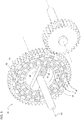
- FIG. 3 shows a schematic representation of the magnetic summation 31.
- the summation 31 includes a first gear member 36, a second gear member 38 and a third gear member 40, which are magnetically coupled together.
- a rotating magnetic field is generated by a rotation of a transmission element 36, 38, 40, which then exerts a force on another transmission element 36, 38, 40.
- a transmission of a moment within the magnetic summation 31 takes place without contact.
- the first transmission element 36 is formed as an inner ring.
- the transmission element 36 is arranged coaxially to a main axis of rotation 42 of the magnetic summation 31.
- the first, designed as an inner ring gear member 36 includes a magnetic element 44.
- the magnetic element 44 is formed in the embodiment as a permanent magnet, preferably as a bar magnet.
- the magnetic element 44 is aligned at a right angle to the main axis of rotation 42.
- the magnetic element 44 has a north pole and a south pole. In this case, the north pole is arranged at a radial end of the magnetic element 44 and the south pole at an opposite radial end.
- the second gear member 38 is formed as a center ring and surrounds the first, formed as an inner ring, transmission element 36 in a circumferential direction completely.
- the second transmission element 38 comprises magnetically conductive elements 46 and magnetically non-conductive elements 48.
- the magnetically conductive elements 46 and the magnetically non-conductive elements 48 are arranged alternately.
- the magnetically conductive elements 46 and the magnetically non-conductive elements 48 are firmly connected to each other.
- the third transmission element 40 is formed as an outer ring.
- the transmission element 40 is arranged radially outside of the second transmission element 38 designed as a center ring.
- the third transmission element 40 comprises magnetic elements 50, 52.
- the magnetic elements 50, 52 are firmly integrated into the transmission element 40 formed as an outer ring.
- the magnetic elements 50, 52 are distributed over the entire 360 degrees of the annular transmission element 40 and aligned in a radial direction.
- a north pole and a south pole of a magnetic element 50, 52 each lie in an imaginary axis which extends radially outward from the main axis of rotation.
- a polarization of two adjacent magnetic elements 50, 52 of the third transmission element 40 is reversed.
- the north pole of one magnetic element 50 is directed radially inward in the direction of the main rotational axis
- the north pole of the circumferentially adjacent magnetic element 52 is directed radially outward from the main rotational axis.
- the south pole of one magnetic element 50 is then directed radially outward from the main axis of rotation, and the south pole of the circumferentially adjacent magnetic element 52 is directed radially inward toward the main axis of rotation.
- all the magnetic elements 50, 52 of the third gear element 40 are reversely polarized to the adjacent magnetic elements 50, 52 are arranged.
- the magnetic elements 50, 52 of the outer ring formed as a third gear member 40 may be formed as permanent magnets.
- the magnetic summing 31 has a fixed ratio.
- the magnetic elements 50, 52 are formed as controllable magnetic coils, so that the magnetic summation 31 can form a variable translation by a special control and thus a continuous variation of the flow is possible ,
Landscapes
- Engineering & Computer Science (AREA)
- Chemical & Material Sciences (AREA)
- Combustion & Propulsion (AREA)
- Transportation (AREA)
- Mechanical Engineering (AREA)
- Arrangement And Driving Of Transmission Devices (AREA)
Abstract
Description
- Die Erfindung betrifft landwirtschaftliches Fahrzeug mit einen Verbrennungsmotor zum Allradantrieb einer Vorderachse und einer Hinterachse, wobei das Fahrzeug eine Anordnung zur dynamischen Anpassung des Vorlaufs aufweist.
- Die derzeit häufigste herkömmliche Variante eines Allradantriebs nach dem Stand der Technik besteht aus einem Verbrennungsmotor, dessen Leistung auf mehrere Achsen und Räder verteilt werden soll. Herkömmliche Allradantriebe kann man in zwei Grundtypen einteilen.
- Bei dem ersten herkömmlichen Grundtyp handelt es sich um differenzialgesteuerte oder permanente Allradantriebe. Diese besitzen ein Zentraldifferential (auch: Längsdifferenzial, Mittendifferenzial), welches die Antriebsleistung permanent auf beide Achsen aufteilt und manchmal als Sperrdifferenzial ausgeführt ist. Das Zentraldifferenzial ist bei herkömmlichen Varianten nach den Stand der Technik häufig ein Planetengetriebe, gelegentlich auch als Differenzial ausgeführt, da dies ein spezielles Planetengetriebe mit einer 50:50-Drehmoment-Aufteilung ist. Alternativ können auch Differenziale ohne Verzahnung, wie zum Beispiel Gleitsteindifferenziale, eingesetzt werden.
- Bei dem zweiten herkömmlichen Grundtyp nach dem Stand der Technik handelt es sich um Kupplungsgesteuerte Allradantriebe. Bei diesen Systemen wird eine Achse permanent angetrieben, die andere Achse wird nur unter bestimmten Voraussetzungen über eine Kupplung mit Antriebsleistung versorgt. Die Kupplung selbst kann eine einfache Klauenkupplung, eine Visco-Kupplung, eine Fliehkraftkupplung oder eine elektronisch gesteuerte Reiblamellenkupplung sein.
- Bei Fahrzeugen mit permanentem Allradantrieb wird die Motorleistung ständig auf alle vier Räder übertragen und durch die Differenziale wird der vollständige Drehzahlausgleich ohne Leistungsverluste gewährleistet. Um Verspannungen im Antriebsstrang zu vermeiden, wird häufig ein zusätzliches Zentraldifferenzial zwischen Vorder- und Hinterachse eingebaut. Der Nachteil hierbei ist jedoch, dass bei fehlender Bodenhaftung eines einzelnen Rades oder einer Achse das übertragbare Antriebsmoment durch dieses Rad oder diese Achse begrenzt wird, wodurch ein Fahrzeug im Extremfall nicht mehr aus eigener Kraft bewegt werden kann. Aus diesem Grund wird bei Fahrzeugen mit permanentem Allradantrieb häufig entweder das Zentraldifferenzial als Sperrdifferenzial ausgeführt oder es kommen elektronische Traktionshilfen zum Einsatz.
- Durch die Bauart des Zentraldifferenzials kann das Antriebsmoment gleichmäßig (50:50) oder auch ungleichmäßig auf beide Achsen aufgeteilt werden. Die Wahl der Verteilung bestimmt das Fahrverhalten maßgeblich. Da an Steigungen und beim Beschleunigen durch die dynamische Achslastverschiebung zusätzlich Gewicht auf die Hinterachse verlagert wird, ist es üblich, auch beim Antriebsmoment einen höheren Anteil auf die Hinterachse zu übertragen. Daher werden in vielen Fahrzeugen die Drehmoment-Aufteilungen zwischen Vorderachse und Hinterachse von 45:55 (V:H) bis 33:67 gewählt. Diese Verteilung ist zunächst zwar festgelegt, wird aber durch die Sperre des Zentraldifferenzials wieder erweitert. Bei einem Zentraldifferenzial mit elektronischer Reiblamellenkupplung können sich durch äußere Gegebenheiten sogar Kraftverteilungen von 100 : 0 und 0 : 100 einstellen.
- Mittels einer Antriebswelle wird das Drehmoment auf ein Hauptgetriebe übertragen, welches durch eine Abtriebswelle mit einem Differential in Verbindung steht. Das Differential verteilt das bereitgestellte Drehmoment zum Antreiben einer oder beider Fahrzeugachsen auf diese. Zwischen dem Differential und der ersten Fahrzeugachse ist ein Getriebe zur Einstellung eines Drehmoment- und/oder eines Drehzahlverhältnisses zwischen den angetriebenen Fahrzeugachsen angeordnet.
- Eine starre Kopplung der Antriebsachsen bei allradgetriebenen landwirtschaftlichen Fahrzeugen, wie beispielsweise Traktoren mit Achsschenkellenkung, führt bei Kurvenfahrt zu einem ungünstigen Fahrverhalten. Die größere Geschwindigkeit der Vorderräder beim Kurvenfahren wegen des weiteren Spurkreises der Vorderachse ist besonders bei der fast ausschließlich verwendeten Achsschenkel-Lenkung problematisch. Gerade bei Traktoren mit den relativ kurzen Radständen und der für verschiedene Arbeiten unabdingbaren Wendigkeit müssen daher Lösungen gefunden werden.
- Der Quotient aus der mittleren Radumfangsgeschwindigkeit der Vorder- und Hinterräder ist eine gebräuchliche Größe zur Beschreibung der Abrollkinematik. Bei einem Verhältnis größer als 1 spricht man von Vorlauf oder auch Voreilung der Vorderräder. Der Vorlaufbedarf bei Kurvenfahrt kann abgeschätzt werden. So kann beispielsweise mit Hilfe von Federkennlinien der Reifen in einer rechnerischen Modellierung der praxisrelevante Bereich für den statischen Vorlauf auf ermittelt werden.
- Wegen der geforderten Rangierbarkeit wurden die Radeinschlagwinkel mit immer weiter verfeinerten Außenantriebsgelenken bis zu 50 Grad gesteigert. Bei diesem maximalen Einschlagwinkel drehen die Vorderräder fast 30 Prozent schneller als die Hinterräder. Bei starren Allradantrieben treten bei dieser Drehzahldifferenz unerlaubt hohe Blindmomente mit reduzierter Zugleistung und erhöhtem Verschleiß auf.
- Es besteht die Möglichkeit, der manuellen oder automatischen Abschaltung des Vorderradantriebs beim Befahren enger Kurvenradien. Hierbei nimmt dementsprechend die zur Verfügung stehende Zugkraft der Vorderachse in Kurven ab.
- Es ist eine Anpassung der Vorderachsgeschwindigkeit beim Kurvenfahren bekannt, bei der die Vorderachse bei Geradeausfahrt und bei kleineren Lenkwinkeln über eine geschlossene Klauenkupplung mit einer bestimmten Übersetzung angetrieben wird. Bei größeren Lenkwinkeln über 40 Grad wird die Klauenkupplung geöffnet und eine Lamellenkupplung geschlossen, die nunmehr die Vorderräder über eine höhere Übersetzung schneller antreibt.
- Es ist bekannt, dass der Wechsel der Übersetzung zur Vorderachse vollautomatisch erfolgt. Nachteilig bei dieser Lösung ist, dass die exakte Drehzahlanpassung der Vorderachse beim Kurvenfahren nur in zwei Auslegungspunkten vorgenommen wird. In den anderen Bereichen werden zwar reduzierte, aber doch signifikante Blindmomente erzeugt.
- Es ist ebenfalls bekannt, durch den Einsatz eines hydrostatisches Überlagerungsgetriebes, die richtige Drehzahl der Vorderräder für alle Kurvenradien und Schlupfbedingungen optimal einzustellen.
- Die
DE 10 2015 114 055 A1 beschreibt ein landwirtschaftliches Fahrzeug mit einem Verbrennungsmotor, welcher mittels einer Antriebswelle ein Drehmoment auf ein Hauptgetriebe überträgt. Das Hauptgetriebe steht über eine Abtriebswelle mit einem Differential in Verbindung. Das Differential verteilt das Drehmoment zum Antreiben einer oder beider Fahrzeugachsen. Zwischen dem Differential und der ersten Fahrzeugachse ist ein Getriebe zur Einstellung eines Drehmoment- und/oder eines Drehzahlverhältnisses zwischen den angetriebenen Fahrzeugachsen angeordnet. Das Getriebe ist als ein stufenloses Getriebe ausgeführt. - Die
DE 10 2005 044 181 A1 offenbart ein Antriebssystem für einen Traktor. Das Antriebssystem umfasst mindestens einen elektrischen Generator, sowie eine erste und zweite elektrische Maschine. Mit einem vom Motor erzeugten Drehmoment wird ein elektrische Generator angetrieben. Mit der vom elektrischen Generator erzeugten elektrischen Energie wird eine der beiden elektrischen Maschinen angetrieben. Das von der ersten und/oder der zweiten elektrischen Maschine erzeugte mechanische Drehmoment ist auf mindestens eine Antriebsachse des Fahrzeugs zu dessen Fortbewegung übertragbar. In einer bevorzugten Ausführungsform ist eine Antriebsachse lediglich von einer elektrischen Maschine antreibbar und eine andere Antriebsachse lediglich von der anderen elektrischen Maschine antreibbar. Hierdurch können die Räder der Vorderachse mit einer anderen Radumfangs-geschwindigkeit als die Räder der Hinterachse betrieben werden. Durch eine Erhöhung des Vorlaufs der Räder der Vorderachse kann der Wendekreis des Traktors verkleinert werden. In derDE 10 2013 224 383 A1 wird ein leistungsverzweigter Achsantrieb beschrieben. Dieser umfasst ein Hauptantriebselement, zwei Zusatzantriebselemente, zwei Fahrzeugachsen und ein Hauptgetriebe. Ein leistungsverzweigter Achsantrieb weist ein Leistungsverzweigungsgetriebe auf. Ein Zusatzantriebselement wirkt auf das Leistungsverzweigungsgetriebe ein. Dadurch ist der Vorlauf der zweiten Fahrzeugachse regelbar. - Die
DE 10 2015 209 244 A1 beschreibt ein Verfahren, bei dem durch Beaufschlagung der Synchron-Soll Drehzahl mit einem vordefinierten Differenz-Korrekturfaktor die Soll-Drehzahl einer zweiten Achse gezielt relativ zur Ist-Drehzahl der ersten Achse eingestellt werden kann. Dadurch kann ein Vorlauf eingestellt werden. - Die
DE 10 2013 226 592 A1 betrifft ein Verfahren zur Reduzierung des Vorlaufs mittels einer Reifendruckregelanlage. Dabei wird der Luftdruck der Vorderachse verringert und der Luftdruck der Hinterachse erhöht. Auf diese Weise kann der Vorlauf reduziert werden, indem durch Anpassen der Radabmessungen die translatorischen Geschwindigkeiten der Räder an der ersten Achse und der zweiten Achse einander angeglichen werden. - Aufgabe der Erfindung ist es, ein landwirtschaftliches Fahrzeug mit einem Allradantrieb weiterzuentwickeln.
- Diese Aufgabe wird erfindungsgemäß durch ein landwirtschaftliches Fahrzeug gemäß dem Hauptanspruch und eine Verwendung gemäß dem Nebenanspruch gelöst. Bevorzugte Varianten sind den Unteransprüchen, der Beschreibung und den Zeichnungen zu entnehmen.
- Erfindungsgemäß weist das Fahrzeug eine Anordnung zur dynamischen Anpassung des Vorlaufs einer Achse auf. Diese Möglichkeit einer dynamischen Anpassung während des Fahrbetriebes bringt erhebliche Vorteile gegenüber herkömmlichen Fahrzeugen mit einem starren Übersetzungsverhältnis mit sich. Es ist möglich, die Vorderachse flexibel mit einer unterschiedlichen Drehzahl als die Hinterachse zu betreiben. Durch eine unterschiedliche Drehzahl kann das Kurvenfahrverhalten aktiv beeinflusst werden, so dass ein kleinerer Kurvenradius eingehalten werden kann. Das erfindungsgemäße Fahrzeug ermöglicht es auch, dass beispielsweise bei einer Geradeausfahrt kein Vorlauf vorhanden ist und nur bei einer Kurvenfahrt ein Vorlauf vorgenommen wird.
- Erfindungsgemäß wird ein magnetisches Summiergetriebe zur dynamische Anpassung des Vorlaufs eingesetzt. Solche magnetischen Summiergetriebe sind prinzipiell beispielsweise aus der
DE 10 2013 021 224 A1 bekannt. Der Einsatz eines solchen magnetischen Summiergetriebes zur dynamischen Einstellung des Vorlaufs hat beispielsweise gegenüber dem Einsatz von mechanischen Summiergetrieben große Vorteile. Mechanische Überlagerungsgetriebe, die diese Funktion erfüllen, müssten sehr hohe Übersetzungsverhältnisse erreichen und zusätzlich Sicherheitseinrichtungen zum Schutz vor Überdrehzahl bei schnellen engen Kurven implementieren, was einen sehr hohen konstruktiven Aufwand und damit hohe Kosten nach sich zieht. Dagegen kann das magnetische Summiergetriebe in einer Stufe hohe Übersetzungsverhältnisse realisieren und weist eine inhärente Sicherheit gegen Überbelastung, beispielsweise einer Überdrehzahl auf, die keiner zusätzlich konstruktiv zu realisierenden schaltbaren trennbaren Verbindung bedarf. - Bei dem Summiergetriebe sind mindestens zwei Getriebeelemente magnetisch miteinander gekoppelt. Bei einer besonders vorteilhaften Variante der Erfindung ist ein drittes Getriebeelement ebenfalls mit zumindest einem der beiden anderen Getriebeelemente magnetisch gekoppelt.
- Eine Übertragung eines Moments zwischen den Getriebeelementen erfolgt über magnetische Felder. Dabei wird durch eine Rotation eines Getriebeelements ein rotierendes Magnetfeld erzeugt, welches dann eine Kraftwirkung auf ein anderes Getriebeelement ausübt. Eine Übertragung eines Moments innerhalb des Summiergetriebes erfolgt kontaktfrei.
- Bei einer Variante der Erfindung ist das erste Getriebeelement als ein Innenring ausgebildet. Es umfasst Magnetelemente die vorzugsweise als Permanentmagnete ausgebildet sind. Diese sind vorzugsweise in einem rechten Winkel zu der Hauptrotationsachse des Summiergetriebes ausgerichtet.
- Als besonders günstig erweist es sich, wenn das zweite Getriebeelement als ein Mittelring ausgebildet ist. Dabei umschließt das als Mittelring ausgebildete zweite Getriebeelement das erste, als Innenring ausgebildete Getriebeelement. Das zweite Getriebeelement umfasst magnetisch leitende Elemente und magnetisch nichtleitende Elemente, die jeweils abwechselnd angeordnet sind.
- Bei einer vorteilhaften Variante der Erfindung ist das dritte Getriebeelement als ein Außenring ausgebildet. Das als Außenring ausgebildete Getriebeelement ist radial außerhalb des als Mittelring ausgebildeten zweiten Getriebeelements angeordnet. Das als Außenring ausgebildete, dritte Getriebeelement umfasst Magnetelemente, die in einer Radialrichtung ausgerichtet sind.
- Das landwirtschaftliche Fahrzeug umfasst vorzugsweise eine Einrichtung, mit der die auf die Vorderachse und Hinterachse übertragenen Drehmomente variiert werden können, wenn es beispielsweise in Folge von Schlupf zu einem Traktionsverlust kommt. Die Einrichtung kann die Relativdrehzahl einzelner Komponenten des magnetischen Summiergetriebes regeln. Es kann die Summierung von elektrischer und mechanischer Leistung eingestellt werden. Durch die Einrichtung kann die Leistungsverteilung zwischen der Vorder- und der Hinterachse gezielt geregelt werden. Es ist somit möglich, eine flexible Leistungsverteilung zu realisieren, die an den aktuellen Lastfall angepasst ist. Dies kann beispielsweise durch das Einstellen der Relativdrehzahlen des magnetischen Summiergetriebes erfolgen.
- Mit der Anordnung zur dynamischen Anpassung des Vorlaufs einer Achse kann die Antriebsleistung in Form von elektrischer und von mechanischer Leistung an eine Achse, vorzugsweise die Vorderachse, geleitet werden. Dabei überlagern sich beide Leistungspfade im magnetischen Summiergetriebe. Es kann auch eine Boostfunktion integriert werden, welche im Bedarfsfall über die elektrische Maschine eine zusätzliche kurzzeitig erhöhte elektrische Leistung auf die Vorderachse leitet. Die Boostfunktion erfolgt auf dem elektrischen Leistungspfad. Die Boostfunktion ermöglicht es, im Fall von kurzfristig benötigter Antriebsleistung, einen zusätzlichen Anteil der Leistung über den elektrischen Leistungspfad hinzuzufügen.
- Bei einer Ausführung der Erfindung können der Generator und wenigstens eine elektrische Maschine mit wenigstens einem Energiespeicher, einem Akkumulator oder einer Batterie verbunden sein. Durch das Verbinden kann der Generator den Energiespeicher aufladen und elektrische Energie für eine spätere Verwendung speichern. In einem Betriebsmodus, in dem nur eine geringe elektrische Leistung im Abtrieb benötigt wird, kann daher die elektrische Leistung wenigstens teilweise in den Energiespeicher, den Akkumulator oder die Batterie geleitet werden. Diese steht für einen späteren Abruf bei Leistungsbedarf zur Verfügung.
- Bei einer Variante der Erfindung kann die Anordnung derart ausgelegt sein, dass bei einem Bremsvorgang eine Rekuperation der Antriebsleistung erfolgt. Es kann ein Anteil der durch den Bremsvorgang anfallenden Leistung mittels der elektrischen Maschine wieder in elektrischen Strom umgewandelt werden. Die elektrische Maschine erzeugt im Generatormodus Strom, der an den Energiespeicher weitergeleitet wird. Somit steht ein Teil der Bremsleistung zu einem späteren Zeitpunkt erneut zur Verfügung.
- Bei einer weiteren Ausführung werden wenigstens zwei elektrische Maschinen eingesetzt. Dies ermöglicht es beide Vorderräder mit unterschiedlichen Drehzahlen oder unterschiedlichen Drehmomenten zu betreiben. Dadurch kann ein Vorderrad gezielt gebremst oder beschleunigt werden. Dieses Verfahren kann zur Stabilisierung des Fahrzeugs bei kritischen Fahrzuständen eingesetzt werden.
- In einer weiteren Ausführung ist die Antriebsleistungsaufteilung auf die Abtriebsmittel der Vorder- und der Hinterachse regulierbar. Die Aufteilung der Antriebsleistung erlaubt über den Vierradantrieb hinaus die Stabilisierung des Fahrzeugs. Bei unterschiedlichem Untergrund mit wechselndem Rad-Boden-Kontakt, wie etwa Erdreich, und bei unterschiedlichen Steigungen, kann eine verbesserte Zugleistung des Fahrzeugs erreicht werden.
- Weitere Merkmale und Vorteile der Erfindung ergeben sich aus der Beschreibung von Ausführungsbeispielen anhand von Figuren und aus den Figuren selbst.
- Dabei zeigt
- Figur 1
- eine schematische Darstellung eines landwirtschaftlichen Fahrzeugs,
- Figur 2
- eine schematische Darstellung eines Antriebsstrangs mit einer Anordnung zur dynamischen Anpassung des Vorlaufs,
- Figur 3
- eine schematische Darstellung eines magnetischen Summiergetriebes.
-
Figur 1 zeigt ein landwirtschaftliches Fahrzeug 10, welches im Ausführungsbeispiel als Traktor ausgeführt ist mit einer Vorderachse 12 und einer Hinterachse 14. An den Achsen 12, 14 befinden sich Räder, jedoch können statt Rädern auch Ketten- oder Raupenantriebe zur Anwendung kommen. -
Figur 2 zeigt eine schematische Darstellung eines Antriebsstrangsystems mit einer Anordnung 20 zur dynamischen Anpassung des Vorlaufs. - Die Vorderachse 12 und die Hinterachse 14 können über einen mechanischen Leistungspfad angetrieben werden. Dabei wird die mechanisch erzeugte Leistung eines Verbrennungsmotors 21 mittels eines Schalt-/Automatikgetriebes 30, einem Vorderachsdifferential 27 und einem Hinterachsdifferential 29 zugeleitet.
- Erfindungsgemäß werden die Vorderräder zusätzlich mit einer auf elektrischem Wege erzeugten Leistung beaufschlagt. Hierfür ist ein Generator 22 vorgesehen, der mit dem Verbrennungsmotor 21 verbunden ist. Durch die Antriebsleistung des Verbrennungsmotors 21 erzeugt der Generator 22 elektrischen Strom, welcher dann für eine zusätzliche Leistungsbeaufschlagung der Vorderachse 12 zur Verfügung gestellt wird.
- Bei einer Variante der Erfindung kann der elektrische Strom zunächst in einem Energiespeicher 34 gespeichert werden. Es kann jedoch auch vorgesehen sein, keinen Energiespeicher 34 unterzubringen, so dass der elektrische Strom vom Generator 22 direkt zur Leistungserzeugung genutzt wird.
- Der elektrische Strom wird vom Generator 22 oder vom Energiespeicher 34 an eine elektrische Maschine 23 weitergeleitet. Die elektrische Maschine 23 erzeugt aus dem elektrischen Strom Antriebsleistung. Erfindungsgemäß kann die Vorderachse 12 zusätzlich zu der Leistung des mechanischen Pfades mit einer Leistung aus dem elektrischen Pfad beaufschlagt werden.
- Das Schalt- oder Automatikgetriebe 30 dient dazu, die Leistung bezüglich Drehmoment bzw. Drehzahl an den Bedarfsfall anzupassen. Durch eine Zahnradstufe 25 kann die mechanisch erzeugte Leistung des Verbrennungsmotors 21 auf einen Vorderachs- und/oder Hinterachsantrieb aufgeteilt werden.
- Der Antrieb der Hinterachse 14 weist im Ausführungsbeispiel ein Hinterachsdifferential 29 auf, an das die Abtriebsmittel 28 der Hinterachse angeschlossen sind. Dabei können die Abtriebsmittel aus einem Differenzialgetriebe, einem Planetengetriebe oder einem Umlaufrädergetriebe bestehen, und dienen dazu, die Drehzahl und/oder das Drehmoment nochmals zu modifizieren, bevor es an die Räder geleitet wird.
- Der Leistungspfad für die Vorderachse 12 weist erfindungsgemäß ein magnetisches Summiergetriebe 31 auf, das die Leistung aus dem mechanischen und dem elektrischen Pfad bündelt und an ein Vorderachsdifferential 27 leitet. Ausgehend vom Vorderachsdifferential 27 wird die Leistung an die Abtriebsmittel 26 der Vorderachse weitergeleitet. Diese haben die gleiche Funktion wie die Abtriebsmittel 28 der Hinterachse.
- Die elektrische Maschine 23 ist auf ihrer mechanischen Seite mit dem magnetischen Summiergetriebe 31 verbunden. In dem magnetischen Summiergetriebe 31 wird der mechanische Leistungspfad mit dem elektrischen Leistungspfad addiert und an die Vorderachse 12 geleitet.
- Durch die Anordnung 20 zur dynamischen Anpassung des Vorlaufs ist es möglich, je nach Bedarfsfall zusätzlich die Leistung aus dem elektrischen Pfad zu dosieren. Die elektrische Maschine 23 wird durch eine nicht dargestellte Einrichtung gesteuert, so dass die elektrische Maschine 23 durch ihren elektrischen Antrieb das magnetische Summiergetriebe 31 derart beeinflussen kann, dass die Leistung bedarfsgerecht summiert wird. Je nach Drehzahlunterschied der einzelnen Elemente des magnetischen Summiergetriebes 31 kann der Faktor der Summierung bestimmt werden.
- Die Einrichtung zur Steuerung und/oder Regelung kann auch dazu verwendet werden, den Generator 22 zu steuern, so dass dieser je nach Bedarfsfall zu bzw. abgeschaltet werden kann.
- Durch den elektrischen Leistungspfad kann mithilfe der Einrichtung zur Steuerung und/oder Regelung im Bedarfsfall zusätzliche elektrische Leistung auf die Vorderachse 12 geleitet werden. Der elektrische Leistungspfad führt nicht über das Getriebe 30, sodass dieses durch die summierte Leistung nicht belastet wird.
- Durch die Steuerung des magnetischen Summiergetriebes 31 kann auch eine Leistungsverteilung zwischen der Vorderachse 12 und der Hinterachse 14 erreicht werden. Durch die aktive Steuerung des magnetischen Summiergetriebes 31 kann die Leistung von der Vorderachse 12 auf die Hinterachse 14 umverteilt werden. Die Leistungsverteilung zwischen der Vorder- und der Hinterachse 12, 14 kann bedarfsgerecht gesteuert sein.
- Durch die zusätzliche elektrische Leistung wird die Vorderachse 12 mit einem Vorlauf ausgestattet. Die Abtriebsmittel der Vorderachse 12 drehen dabei mit einer höheren oder niedrigeren Drehzahl als diejenigen der Hinterachse 14. Das Fahrzeug 10 weist bei Kurvenfahrt ein besseres Ansprechverhalten auf.
- Beim Abbremsvorgang kann ein Anteil der Leistung durch die elektrische Maschine 23 im Generatorbetrieb in elektrischen Strom gewandelt und im Energiespeicher 34 gespeichert werden.
-
Figur 3 zeigt eine schematische Darstellung des magnetischen Summiergetriebes 31. Das Summiergetriebe 31 umfasst ein erstes Getriebeelement 36, ein zweites Getriebeelement 38 und ein drittes Getriebeelement 40, die magnetisch miteinander gekoppelt sind. Eine Übertragung eines Moments zwischen den Getriebeelementen 36, 38 und 40 erfolgt über magnetische Felder. Dabei wird durch eine Rotation eines Getriebeelements 36, 38, 40 ein rotierendes Magnetfeld erzeugt, welches dann eine Kraftwirkung auf ein anderes Getriebeelement 36, 38, 40 ausübt. Eine Übertragung eines Moments innerhalb des magnetischen Summiergetriebes 31 erfolgt kontaktfrei. - Das erste Getriebeelement 36 ist als ein Innenring ausgebildet. Das Getriebeelement 36 ist koaxial zu einer Hauptrotationsachse 42 des magnetischen Summiergetriebes 31 angeordnet. Das erste, als Innenring ausgebildete Getriebeelement 36 umfasst ein Magnetelement 44. Das Magnetelement 44 ist im Ausführungsbeispiel als ein Permanentmagnet ausgebildet, vorzugsweise als Stabmagnet. Das Magnetelement 44 ist in einem rechten Winkel zu der Hauptrotationsachse 42 ausgerichtet. Das Magnetelement 44 weist dabei einen Nordpol und einen Südpol auf. Dabei ist der Nordpol an einem radialen Ende des Magnetelements 44 und der Südpol an einem gegenüberliegenden radialen Ende angeordnet.
- Das zweite Getriebeelement 38 ist als Mittelring ausgebildet und umschließt das erste, als Innenring ausgebildete, Getriebeelement 36 in einer Umfangsrichtung komplett.
- Das zweite Getriebeelement 38 umfasst magnetisch leitende Elemente 46 und magnetisch nichtleitende Elemente 48. Die magnetisch leitenden Elemente 46 und die magnetisch nichtleitenden Elemente 48 sind abwechselnd angeordnet. Die magnetisch leitenden Elemente 46 und die magnetisch nichtleitenden Elemente 48 sind fest miteinander verbunden.
- Das dritte Getriebeelement 40 ist als ein Außenring ausgebildet. Das Getriebeelement 40 ist radial außerhalb des als Mittelring ausgebildeten zweiten Getriebeelements 38 angeordnet. Das dritte Getriebeelement 40 umfasst Magnetelemente 50, 52. Die Magnetelemente 50, 52 sind in das als Außenring ausgebildete Getriebeelement 40 fest integriert.
- Die Magnetelemente 50, 52 sind dabei über die gesamten 360 Grad des ringförmig ausgebildeten Getriebeelements 40 verteilt und in einer Radialrichtung ausgerichtet. Dabei liegen ein Nordpol und ein Südpol eines Magnetelements 50, 52 jeweils in einer imaginären Achse, die von der Hauptrotationsachse aus radial nach außen verläuft.
- Eine Polarisierung zweier benachbarter Magnetelemente 50, 52 des dritten Getriebeelements 40 ist dabei umgekehrt. Dabei ist der Nordpol des einen Magnetelements 50 radial nach innen in Richtung der Hauptrotationsachse gerichtet, und der Nordpol des in Umfangsrichtung benachbarten Magnetelements 52 ist radial nach außen von der Hauptrotationsachse weggerichtet.
- Äquivalent dazu ist dann der Südpol des einen Magnetelements 50 radial nach außen von der Hauptrotationsachse weggerichtet und der Südpol des in Umfangsrichtung benachbarten Magnetelements 52 ist radial nach innen in Richtung der Hauptrotationsachse gerichtet. Dabei sind alle Magnetelemente 50, 52 des dritten Getriebeelements 40 umgekehrt polarisiert zu dem benachbarten Magnetelemente 50, 52 angeordnet.
- Die Magnetelemente 50, 52 des als Außenring ausgebildeten, dritten Getriebeelements 40 können als Permanentmagnete ausgebildet sein. Bei dieser Variante weist das magnetische Summiergetriebe 31 eine feste Übersetzung auf.
- Bei einer bevorzugten Variante der Erfindung, die nicht in den Figuren dargestellt ist, sind die Magnetelemente 50, 52 als steuerbare Magnetspulen ausgebildet, so dass das magnetische Summiergetriebe 31 durch eine spezielle Ansteuerung eine variable Übersetzung ausbilden kann und somit eine stufenlose Variation des Vorlauf möglich ist.
Claims (12)
- Landwirtschaftliches Fahrzeug (10) mit einem Verbrennungsmotor (21) zum Allradantrieb einer Vorderachse (12) und einer Hinterachse (14), dadurch gekennzeichnet, dass das Fahrzeug (10) eine Anordnung (20) zur dynamischen Anpassung des Vorlauf einer Achse (12, 14) aufweist, wobei die Anordnung (20) eine elektrische Maschine (23) und ein Summiergetriebe (31) umfasst, das die Antriebskraft des Verbrennungsmotors (21) und der elektrischen Maschine (23) summiert, wobei das Summiergetriebe (31) mindestens zwei Getriebeelemente (36, 38, 40) aufweist, die magnetisch gekoppelt sind.
- Landwirtschaftliches Fahrzeug nach Anspruch 1 , dadurch gekennzeichnet, dass das Summiergetriebe (31) ein erstes Getriebeelement (36) zur Anbindung des Verbrennungsmotors (21), ein zweites Getriebeelement (38) zur Anbindung der elektrischen Maschine (23) und ein drittes Getriebeelement (40) als Ausgangselement aufweist.
- Landwirtschaftliches Fahrzeug nach Anspruch 2, dadurch gekennzeichnet, dass das dritte Getriebeelement (40) mit einen Vorderachsdifferential (27) verbunden ist.
- Landwirtschaftliches Fahrzeug nach einem der Ansprüche 1 bis 3, dadurch gekennzeichnet, dass ein Getriebeelement (36) als Innenring, ein Getriebeelement (40) als Außenring und ein Getriebeelement (38) als Mittelring ausgebildet ist, wobei die Getriebeelemente (36, 38, 40) jeweils magnetisch miteinander gekoppelt sind.
- Landwirtschaftliches Fahrzeug nach Anspruch 4, dadurch gekennzeichnet, dass die elektrische Maschine (23) unmittelbar um den Außenring angeordnet ist.
- Landwirtschaftliches Fahrzeug nach einen der Ansprüche 4 oder 5, dadurch gekennzeichnet, dass das als Außenring ausgebildete Getriebeelement (40) als ein Eingangsrad eines Differentialgetriebes ausgeführt ist.
- Landwirtschaftliches Fahrzeug nach einem der Ansprüche 4 bis 6, dadurch gekennzeichnet, dass das als Außenring ausgebildete Getriebeelement (40) Magnetelemente (50, 52) aufweist.
- Landwirtschaftliches Fahrzeug nach einem der Ansprüche 4 bis 7, dadurch gekennzeichnet, dass das als Außenring ausgebildete Getriebeelement (40) ein magnetisches Feld mit Spulen erzeugt.
- Landwirtschaftliches Fahrzeug nach einem der Ansprüche 1 bis 8, dadurch gekennzeichnet, dass die Anordnung (20), die zum Betrieb der elektrischen Maschine (23) nötige Energie in einem elektrischen Generator (22) erzeugt und ohne Zwischenspeicher an die elektrische Maschine (21) leitet.
- Landwirtschaftliches Fahrzeug nach einem der Ansprüche 1 bis 9, dadurch gekennzeichnet, dass das Fahrzeug (10) eine Einrichtung aufweist, die dazu eingerichtet ist, das Übersetzungsverhältnis des Summiergetriebes (31) in Abhängigkeit von zumindest einem das Fahrverhalten beeinflussenden Faktor zu steuern und/oder zu regeln.
- Landwirtschaftliches Fahrzeug nach Anspruch 10, dadurch gekennzeichnet, dass die Einrichtung dazu eingerichtet ist, ein Signal auszuwerten, welches den Fahrmodus des landwirtschaftlichen Fahrzeugs (10) repräsentiert.
- Verwendung eines magnetischen Summiergetriebes (31) zur dynamischen Anpassung des Vorlaufs einer Achse (12, 14) bei einem landwirtschaftlichen Fahrzeug (10).
Applications Claiming Priority (1)
| Application Number | Priority Date | Filing Date | Title |
|---|---|---|---|
| DE102018200953.8A DE102018200953A1 (de) | 2018-01-22 | 2018-01-22 | Fahrzeug mit einer Anordnung zur dynamischen Anpassung des Vorlaufs |
Publications (2)
| Publication Number | Publication Date |
|---|---|
| EP3513997A1 true EP3513997A1 (de) | 2019-07-24 |
| EP3513997B1 EP3513997B1 (de) | 2020-12-23 |
Family
ID=65138822
Family Applications (1)
| Application Number | Title | Priority Date | Filing Date |
|---|---|---|---|
| EP19152565.8A Active EP3513997B1 (de) | 2018-01-22 | 2019-01-18 | Fahrzeug mit einer anordnung zur dynamischen anpassung des vorlaufs |
Country Status (3)
| Country | Link |
|---|---|
| US (1) | US11034239B2 (de) |
| EP (1) | EP3513997B1 (de) |
| DE (1) | DE102018200953A1 (de) |
Cited By (2)
| Publication number | Priority date | Publication date | Assignee | Title |
|---|---|---|---|---|
| US10959366B2 (en) * | 2018-03-22 | 2021-03-30 | Deere & Company | Power take-off transmission |
| US11670995B2 (en) | 2020-01-31 | 2023-06-06 | Deere & Company | Method and apparatus for operating a dual rotor electrical machine |
Families Citing this family (2)
| Publication number | Priority date | Publication date | Assignee | Title |
|---|---|---|---|---|
| DE102020119984A1 (de) * | 2020-07-29 | 2022-02-03 | Deere & Company | Getriebesystem |
| DE102023102489A1 (de) * | 2023-02-01 | 2024-08-01 | Deere & Company | Antriebsstrang und Fahrzeug |
Citations (7)
| Publication number | Priority date | Publication date | Assignee | Title |
|---|---|---|---|---|
| DE4108647A1 (de) * | 1991-03-16 | 1992-09-17 | Deere & Co | Radantrieb |
| DE102005044181A1 (de) | 2005-09-15 | 2007-04-19 | Deere & Company, Moline | Antriebssystem für ein Fahrzeug und ein landwirtschaftliches Nutzfahrzeug |
| DE102013021224A1 (de) | 2013-12-17 | 2014-08-14 | Daimler Ag | Hybridantriebsstrangvorrichtung |
| DE102013224383A1 (de) | 2013-11-28 | 2015-05-28 | Zf Friedrichshafen Ag | Leistungsverzweigter Achsantrieb für Arbeitsmaschinen |
| DE102013226592A1 (de) | 2013-12-19 | 2015-06-25 | Zf Friedrichshafen Ag | Verfahren zur Ermittlung eines Reifenschlupfes eines Kraftfahrzeugs |
| DE102015209244A1 (de) | 2015-05-20 | 2016-11-24 | Avl Commercial Driveline & Tractor Engineering Gmbh | Verfahren zur Steuerung einer Raddrehzahl wenigstens eines Rades einer antreibbaren Achse eines zweispurigen Fahrzeugs mit zwei antreibbaren Achsen und zweispuriges Fahrzeug mit wenigstens zwei antreibbaren Achsen |
| DE102015114055A1 (de) | 2015-08-25 | 2017-03-02 | Claas Tractor Sas | Landwirtschaftliches Fahrzeug |
Family Cites Families (1)
| Publication number | Priority date | Publication date | Assignee | Title |
|---|---|---|---|---|
| DE19623738C2 (de) * | 1996-06-14 | 1998-08-06 | Deere & Co | Fahrzeug mit Elektroantrieb |
-
2018
- 2018-01-22 DE DE102018200953.8A patent/DE102018200953A1/de not_active Withdrawn
- 2018-12-07 US US16/213,193 patent/US11034239B2/en active Active
-
2019
- 2019-01-18 EP EP19152565.8A patent/EP3513997B1/de active Active
Patent Citations (7)
| Publication number | Priority date | Publication date | Assignee | Title |
|---|---|---|---|---|
| DE4108647A1 (de) * | 1991-03-16 | 1992-09-17 | Deere & Co | Radantrieb |
| DE102005044181A1 (de) | 2005-09-15 | 2007-04-19 | Deere & Company, Moline | Antriebssystem für ein Fahrzeug und ein landwirtschaftliches Nutzfahrzeug |
| DE102013224383A1 (de) | 2013-11-28 | 2015-05-28 | Zf Friedrichshafen Ag | Leistungsverzweigter Achsantrieb für Arbeitsmaschinen |
| DE102013021224A1 (de) | 2013-12-17 | 2014-08-14 | Daimler Ag | Hybridantriebsstrangvorrichtung |
| DE102013226592A1 (de) | 2013-12-19 | 2015-06-25 | Zf Friedrichshafen Ag | Verfahren zur Ermittlung eines Reifenschlupfes eines Kraftfahrzeugs |
| DE102015209244A1 (de) | 2015-05-20 | 2016-11-24 | Avl Commercial Driveline & Tractor Engineering Gmbh | Verfahren zur Steuerung einer Raddrehzahl wenigstens eines Rades einer antreibbaren Achse eines zweispurigen Fahrzeugs mit zwei antreibbaren Achsen und zweispuriges Fahrzeug mit wenigstens zwei antreibbaren Achsen |
| DE102015114055A1 (de) | 2015-08-25 | 2017-03-02 | Claas Tractor Sas | Landwirtschaftliches Fahrzeug |
Cited By (2)
| Publication number | Priority date | Publication date | Assignee | Title |
|---|---|---|---|---|
| US10959366B2 (en) * | 2018-03-22 | 2021-03-30 | Deere & Company | Power take-off transmission |
| US11670995B2 (en) | 2020-01-31 | 2023-06-06 | Deere & Company | Method and apparatus for operating a dual rotor electrical machine |
Also Published As
| Publication number | Publication date |
|---|---|
| DE102018200953A1 (de) | 2019-07-25 |
| US20190225079A1 (en) | 2019-07-25 |
| EP3513997B1 (de) | 2020-12-23 |
| US11034239B2 (en) | 2021-06-15 |
Similar Documents
| Publication | Publication Date | Title |
|---|---|---|
| EP2946963B1 (de) | Kraftfahrzeug | |
| DE60103064T2 (de) | Fahrzeuggetriebesysteme | |
| DE102009009809B4 (de) | Achsantriebsvorrichtung für eine Achse eines Kraftfahrzeugs sowie Kraftfahrzeug | |
| DE10313928A1 (de) | Hydraulische Kupplungsanordnung | |
| EP3513997B1 (de) | Fahrzeug mit einer anordnung zur dynamischen anpassung des vorlaufs | |
| DE10318423A1 (de) | Drehmomentübertragende Vorrichtung zum bedarfsabhängigen Betreiben einer Nebenantriebsachsanordnung eines allradgetriebenen Fahrzeugs | |
| DE102005003691B4 (de) | Variable Differentialanordnung | |
| DE102008041897A1 (de) | Verfahren zum Betreiben eines Antriebs eines Kraftfahrzeugs sowie Antriebsvorrichtung und elektronisches Steuergerät | |
| DE102013224383A1 (de) | Leistungsverzweigter Achsantrieb für Arbeitsmaschinen | |
| DE112009000303T5 (de) | Achsbaugruppe mit stufenlos verstellbarem Torque Vectoring | |
| DE102012102260A1 (de) | Drehmomentübertragungseinheit mit integriertem Elektroantriebsmotor | |
| DE102022204749B4 (de) | Achssystem, Antriebssystem und Fahrzeug | |
| EP3543058A1 (de) | Zapfwellengetriebe | |
| EP0304594A2 (de) | Elektrische-mechanische Antriebsanlage für ein Vollkettenfahrzeug | |
| DE102016100788B4 (de) | Vorrichtung zum Antreiben eines Fahrzeuges sowie Verfahren zum Steuern einer Vorrichtung und zugehöriges Steuergerät | |
| DE212019000353U1 (de) | Planetengetriebesystem mit Unterbrecher und damit hergestellte Antriebsachse | |
| DE102019129670A1 (de) | Hybrider achsantrieb mit torque-vectoring | |
| DE102021113913A1 (de) | Mehrgang-antriebsbaugruppe für ein arbeitsfahrzeug mit gegabelten kupplungen | |
| DE112007003227T5 (de) | Torque-Vectoring-System | |
| EP3925809A1 (de) | Antriebsstrangsystem | |
| EP0262626A1 (de) | Antriebsvorrichtung von Rädern zweier Achsen | |
| DE102022204745B4 (de) | Achssystem, Antriebssystem und Fahrzeug | |
| DE102022204751B4 (de) | Achssystem, Antriebssystem und Fahrzeug | |
| DE102018205126B4 (de) | Torque Vectoring-Überlagerungseinheit für ein Differenzialausgleichsgetriebe | |
| EP0383144B1 (de) | Antriebsvorrichtung für mindestens zwei Radpaare |
Legal Events
| Date | Code | Title | Description |
|---|---|---|---|
| PUAI | Public reference made under article 153(3) epc to a published international application that has entered the european phase |
Free format text: ORIGINAL CODE: 0009012 |
|
| STAA | Information on the status of an ep patent application or granted ep patent |
Free format text: STATUS: THE APPLICATION HAS BEEN PUBLISHED |
|
| AK | Designated contracting states |
Kind code of ref document: A1 Designated state(s): AL AT BE BG CH CY CZ DE DK EE ES FI FR GB GR HR HU IE IS IT LI LT LU LV MC MK MT NL NO PL PT RO RS SE SI SK SM TR |
|
| AX | Request for extension of the european patent |
Extension state: BA ME |
|
| STAA | Information on the status of an ep patent application or granted ep patent |
Free format text: STATUS: REQUEST FOR EXAMINATION WAS MADE |
|
| 17P | Request for examination filed |
Effective date: 20200124 |
|
| RBV | Designated contracting states (corrected) |
Designated state(s): AL AT BE BG CH CY CZ DE DK EE ES FI FR GB GR HR HU IE IS IT LI LT LU LV MC MK MT NL NO PL PT RO RS SE SI SK SM TR |
|
| GRAP | Despatch of communication of intention to grant a patent |
Free format text: ORIGINAL CODE: EPIDOSNIGR1 |
|
| STAA | Information on the status of an ep patent application or granted ep patent |
Free format text: STATUS: GRANT OF PATENT IS INTENDED |
|
| RIC1 | Information provided on ipc code assigned before grant |
Ipc: B60K 17/348 20060101ALI20200716BHEP Ipc: B60K 17/35 20060101AFI20200716BHEP |
|
| INTG | Intention to grant announced |
Effective date: 20200806 |
|
| GRAS | Grant fee paid |
Free format text: ORIGINAL CODE: EPIDOSNIGR3 |
|
| GRAA | (expected) grant |
Free format text: ORIGINAL CODE: 0009210 |
|
| STAA | Information on the status of an ep patent application or granted ep patent |
Free format text: STATUS: THE PATENT HAS BEEN GRANTED |
|
| AK | Designated contracting states |
Kind code of ref document: B1 Designated state(s): AL AT BE BG CH CY CZ DE DK EE ES FI FR GB GR HR HU IE IS IT LI LT LU LV MC MK MT NL NO PL PT RO RS SE SI SK SM TR |
|
| REG | Reference to a national code |
Ref country code: GB Ref legal event code: FG4D Free format text: NOT ENGLISH |
|
| REG | Reference to a national code |
Ref country code: DE Ref legal event code: R096 Ref document number: 502019000553 Country of ref document: DE |
|
| REG | Reference to a national code |
Ref country code: AT Ref legal event code: REF Ref document number: 1347385 Country of ref document: AT Kind code of ref document: T Effective date: 20210115 |
|
| REG | Reference to a national code |
Ref country code: IE Ref legal event code: FG4D Free format text: LANGUAGE OF EP DOCUMENT: GERMAN |
|
| PG25 | Lapsed in a contracting state [announced via postgrant information from national office to epo] |
Ref country code: GR Free format text: LAPSE BECAUSE OF FAILURE TO SUBMIT A TRANSLATION OF THE DESCRIPTION OR TO PAY THE FEE WITHIN THE PRESCRIBED TIME-LIMIT Effective date: 20210324 Ref country code: NO Free format text: LAPSE BECAUSE OF FAILURE TO SUBMIT A TRANSLATION OF THE DESCRIPTION OR TO PAY THE FEE WITHIN THE PRESCRIBED TIME-LIMIT Effective date: 20210323 Ref country code: FI Free format text: LAPSE BECAUSE OF FAILURE TO SUBMIT A TRANSLATION OF THE DESCRIPTION OR TO PAY THE FEE WITHIN THE PRESCRIBED TIME-LIMIT Effective date: 20201223 Ref country code: RS Free format text: LAPSE BECAUSE OF FAILURE TO SUBMIT A TRANSLATION OF THE DESCRIPTION OR TO PAY THE FEE WITHIN THE PRESCRIBED TIME-LIMIT Effective date: 20201223 |
|
| REG | Reference to a national code |
Ref country code: NL Ref legal event code: MP Effective date: 20201223 |
|
| PG25 | Lapsed in a contracting state [announced via postgrant information from national office to epo] |
Ref country code: BG Free format text: LAPSE BECAUSE OF FAILURE TO SUBMIT A TRANSLATION OF THE DESCRIPTION OR TO PAY THE FEE WITHIN THE PRESCRIBED TIME-LIMIT Effective date: 20210323 Ref country code: LV Free format text: LAPSE BECAUSE OF FAILURE TO SUBMIT A TRANSLATION OF THE DESCRIPTION OR TO PAY THE FEE WITHIN THE PRESCRIBED TIME-LIMIT Effective date: 20201223 Ref country code: SE Free format text: LAPSE BECAUSE OF FAILURE TO SUBMIT A TRANSLATION OF THE DESCRIPTION OR TO PAY THE FEE WITHIN THE PRESCRIBED TIME-LIMIT Effective date: 20201223 |
|
| PG25 | Lapsed in a contracting state [announced via postgrant information from national office to epo] |
Ref country code: NL Free format text: LAPSE BECAUSE OF FAILURE TO SUBMIT A TRANSLATION OF THE DESCRIPTION OR TO PAY THE FEE WITHIN THE PRESCRIBED TIME-LIMIT Effective date: 20201223 Ref country code: HR Free format text: LAPSE BECAUSE OF FAILURE TO SUBMIT A TRANSLATION OF THE DESCRIPTION OR TO PAY THE FEE WITHIN THE PRESCRIBED TIME-LIMIT Effective date: 20201223 |
|
| REG | Reference to a national code |
Ref country code: LT Ref legal event code: MG9D |
|
| PG25 | Lapsed in a contracting state [announced via postgrant information from national office to epo] |
Ref country code: CZ Free format text: LAPSE BECAUSE OF FAILURE TO SUBMIT A TRANSLATION OF THE DESCRIPTION OR TO PAY THE FEE WITHIN THE PRESCRIBED TIME-LIMIT Effective date: 20201223 Ref country code: EE Free format text: LAPSE BECAUSE OF FAILURE TO SUBMIT A TRANSLATION OF THE DESCRIPTION OR TO PAY THE FEE WITHIN THE PRESCRIBED TIME-LIMIT Effective date: 20201223 Ref country code: SM Free format text: LAPSE BECAUSE OF FAILURE TO SUBMIT A TRANSLATION OF THE DESCRIPTION OR TO PAY THE FEE WITHIN THE PRESCRIBED TIME-LIMIT Effective date: 20201223 Ref country code: SK Free format text: LAPSE BECAUSE OF FAILURE TO SUBMIT A TRANSLATION OF THE DESCRIPTION OR TO PAY THE FEE WITHIN THE PRESCRIBED TIME-LIMIT Effective date: 20201223 Ref country code: PT Free format text: LAPSE BECAUSE OF FAILURE TO SUBMIT A TRANSLATION OF THE DESCRIPTION OR TO PAY THE FEE WITHIN THE PRESCRIBED TIME-LIMIT Effective date: 20210423 Ref country code: RO Free format text: LAPSE BECAUSE OF FAILURE TO SUBMIT A TRANSLATION OF THE DESCRIPTION OR TO PAY THE FEE WITHIN THE PRESCRIBED TIME-LIMIT Effective date: 20201223 Ref country code: LT Free format text: LAPSE BECAUSE OF FAILURE TO SUBMIT A TRANSLATION OF THE DESCRIPTION OR TO PAY THE FEE WITHIN THE PRESCRIBED TIME-LIMIT Effective date: 20201223 |
|
| PG25 | Lapsed in a contracting state [announced via postgrant information from national office to epo] |
Ref country code: PL Free format text: LAPSE BECAUSE OF FAILURE TO SUBMIT A TRANSLATION OF THE DESCRIPTION OR TO PAY THE FEE WITHIN THE PRESCRIBED TIME-LIMIT Effective date: 20201223 |
|
| REG | Reference to a national code |
Ref country code: DE Ref legal event code: R097 Ref document number: 502019000553 Country of ref document: DE |
|
| PG25 | Lapsed in a contracting state [announced via postgrant information from national office to epo] |
Ref country code: LU Free format text: LAPSE BECAUSE OF NON-PAYMENT OF DUE FEES Effective date: 20210118 Ref country code: MC Free format text: LAPSE BECAUSE OF FAILURE TO SUBMIT A TRANSLATION OF THE DESCRIPTION OR TO PAY THE FEE WITHIN THE PRESCRIBED TIME-LIMIT Effective date: 20201223 Ref country code: IS Free format text: LAPSE BECAUSE OF FAILURE TO SUBMIT A TRANSLATION OF THE DESCRIPTION OR TO PAY THE FEE WITHIN THE PRESCRIBED TIME-LIMIT Effective date: 20210423 |
|
| REG | Reference to a national code |
Ref country code: BE Ref legal event code: MM Effective date: 20210131 |
|
| PG25 | Lapsed in a contracting state [announced via postgrant information from national office to epo] |
Ref country code: AL Free format text: LAPSE BECAUSE OF FAILURE TO SUBMIT A TRANSLATION OF THE DESCRIPTION OR TO PAY THE FEE WITHIN THE PRESCRIBED TIME-LIMIT Effective date: 20201223 |
|
| PLBE | No opposition filed within time limit |
Free format text: ORIGINAL CODE: 0009261 |
|
| STAA | Information on the status of an ep patent application or granted ep patent |
Free format text: STATUS: NO OPPOSITION FILED WITHIN TIME LIMIT |
|
| PG25 | Lapsed in a contracting state [announced via postgrant information from national office to epo] |
Ref country code: DK Free format text: LAPSE BECAUSE OF FAILURE TO SUBMIT A TRANSLATION OF THE DESCRIPTION OR TO PAY THE FEE WITHIN THE PRESCRIBED TIME-LIMIT Effective date: 20201223 |
|
| 26N | No opposition filed |
Effective date: 20210924 |
|
| PG25 | Lapsed in a contracting state [announced via postgrant information from national office to epo] |
Ref country code: IE Free format text: LAPSE BECAUSE OF NON-PAYMENT OF DUE FEES Effective date: 20210118 Ref country code: ES Free format text: LAPSE BECAUSE OF FAILURE TO SUBMIT A TRANSLATION OF THE DESCRIPTION OR TO PAY THE FEE WITHIN THE PRESCRIBED TIME-LIMIT Effective date: 20201223 |
|
| PG25 | Lapsed in a contracting state [announced via postgrant information from national office to epo] |
Ref country code: SI Free format text: LAPSE BECAUSE OF FAILURE TO SUBMIT A TRANSLATION OF THE DESCRIPTION OR TO PAY THE FEE WITHIN THE PRESCRIBED TIME-LIMIT Effective date: 20201223 |
|
| PG25 | Lapsed in a contracting state [announced via postgrant information from national office to epo] |
Ref country code: IS Free format text: LAPSE BECAUSE OF FAILURE TO SUBMIT A TRANSLATION OF THE DESCRIPTION OR TO PAY THE FEE WITHIN THE PRESCRIBED TIME-LIMIT Effective date: 20210423 |
|
| PG25 | Lapsed in a contracting state [announced via postgrant information from national office to epo] |
Ref country code: BE Free format text: LAPSE BECAUSE OF NON-PAYMENT OF DUE FEES Effective date: 20210131 |
|
| REG | Reference to a national code |
Ref country code: CH Ref legal event code: PL |
|
| PG25 | Lapsed in a contracting state [announced via postgrant information from national office to epo] |
Ref country code: LI Free format text: LAPSE BECAUSE OF NON-PAYMENT OF DUE FEES Effective date: 20220131 Ref country code: CH Free format text: LAPSE BECAUSE OF NON-PAYMENT OF DUE FEES Effective date: 20220131 |
|
| PG25 | Lapsed in a contracting state [announced via postgrant information from national office to epo] |
Ref country code: CY Free format text: LAPSE BECAUSE OF FAILURE TO SUBMIT A TRANSLATION OF THE DESCRIPTION OR TO PAY THE FEE WITHIN THE PRESCRIBED TIME-LIMIT Effective date: 20201223 |
|
| PG25 | Lapsed in a contracting state [announced via postgrant information from national office to epo] |
Ref country code: HU Free format text: LAPSE BECAUSE OF FAILURE TO SUBMIT A TRANSLATION OF THE DESCRIPTION OR TO PAY THE FEE WITHIN THE PRESCRIBED TIME-LIMIT; INVALID AB INITIO Effective date: 20190118 |
|
| PG25 | Lapsed in a contracting state [announced via postgrant information from national office to epo] |
Ref country code: MK Free format text: LAPSE BECAUSE OF FAILURE TO SUBMIT A TRANSLATION OF THE DESCRIPTION OR TO PAY THE FEE WITHIN THE PRESCRIBED TIME-LIMIT Effective date: 20201223 |
|
| PG25 | Lapsed in a contracting state [announced via postgrant information from national office to epo] |
Ref country code: MT Free format text: LAPSE BECAUSE OF FAILURE TO SUBMIT A TRANSLATION OF THE DESCRIPTION OR TO PAY THE FEE WITHIN THE PRESCRIBED TIME-LIMIT Effective date: 20201223 |
|
| REG | Reference to a national code |
Ref country code: AT Ref legal event code: MM01 Ref document number: 1347385 Country of ref document: AT Kind code of ref document: T Effective date: 20240118 |
|
| PG25 | Lapsed in a contracting state [announced via postgrant information from national office to epo] |
Ref country code: AT Free format text: LAPSE BECAUSE OF NON-PAYMENT OF DUE FEES Effective date: 20240118 |
|
| PG25 | Lapsed in a contracting state [announced via postgrant information from national office to epo] |
Ref country code: TR Free format text: LAPSE BECAUSE OF FAILURE TO SUBMIT A TRANSLATION OF THE DESCRIPTION OR TO PAY THE FEE WITHIN THE PRESCRIBED TIME-LIMIT Effective date: 20201223 |
|
| PGFP | Annual fee paid to national office [announced via postgrant information from national office to epo] |
Ref country code: GB Payment date: 20260127 Year of fee payment: 8 |
|
| PGFP | Annual fee paid to national office [announced via postgrant information from national office to epo] |
Ref country code: DE Payment date: 20251219 Year of fee payment: 8 |
|
| PGFP | Annual fee paid to national office [announced via postgrant information from national office to epo] |
Ref country code: AT Payment date: 20260410 Year of fee payment: 5 |
|
| PGFP | Annual fee paid to national office [announced via postgrant information from national office to epo] |
Ref country code: IT Payment date: 20260121 Year of fee payment: 8 |
|
| PGFP | Annual fee paid to national office [announced via postgrant information from national office to epo] |
Ref country code: FR Payment date: 20260126 Year of fee payment: 8 |