EP3513942A1 - Method for molding composite material, and composite material - Google Patents
Method for molding composite material, and composite material Download PDFInfo
- Publication number
- EP3513942A1 EP3513942A1 EP16916228.6A EP16916228A EP3513942A1 EP 3513942 A1 EP3513942 A1 EP 3513942A1 EP 16916228 A EP16916228 A EP 16916228A EP 3513942 A1 EP3513942 A1 EP 3513942A1
- Authority
- EP
- European Patent Office
- Prior art keywords
- resin
- prepreg sheet
- base material
- composite material
- reinforcing base
- Prior art date
- Legal status (The legal status is an assumption and is not a legal conclusion. Google has not performed a legal analysis and makes no representation as to the accuracy of the status listed.)
- Granted
Links
Images



Classifications
-
- B—PERFORMING OPERATIONS; TRANSPORTING
- B29—WORKING OF PLASTICS; WORKING OF SUBSTANCES IN A PLASTIC STATE IN GENERAL
- B29C—SHAPING OR JOINING OF PLASTICS; SHAPING OF MATERIAL IN A PLASTIC STATE, NOT OTHERWISE PROVIDED FOR; AFTER-TREATMENT OF THE SHAPED PRODUCTS, e.g. REPAIRING
- B29C70/00—Shaping composites, i.e. plastics material comprising reinforcements, fillers or preformed parts, e.g. inserts
- B29C70/04—Shaping composites, i.e. plastics material comprising reinforcements, fillers or preformed parts, e.g. inserts comprising reinforcements only, e.g. self-reinforcing plastics
- B29C70/06—Fibrous reinforcements only
- B29C70/10—Fibrous reinforcements only characterised by the structure of fibrous reinforcements, e.g. hollow fibres
- B29C70/16—Fibrous reinforcements only characterised by the structure of fibrous reinforcements, e.g. hollow fibres using fibres of substantial or continuous length
- B29C70/20—Fibrous reinforcements only characterised by the structure of fibrous reinforcements, e.g. hollow fibres using fibres of substantial or continuous length oriented in a single direction, e.g. roofing or other parallel fibres
-
- B—PERFORMING OPERATIONS; TRANSPORTING
- B29—WORKING OF PLASTICS; WORKING OF SUBSTANCES IN A PLASTIC STATE IN GENERAL
- B29C—SHAPING OR JOINING OF PLASTICS; SHAPING OF MATERIAL IN A PLASTIC STATE, NOT OTHERWISE PROVIDED FOR; AFTER-TREATMENT OF THE SHAPED PRODUCTS, e.g. REPAIRING
- B29C70/00—Shaping composites, i.e. plastics material comprising reinforcements, fillers or preformed parts, e.g. inserts
- B29C70/003—Shaping composites, i.e. plastics material comprising reinforcements, fillers or preformed parts, e.g. inserts characterised by the matrix material, e.g. material composition or physical properties
- B29C70/0035—Shaping composites, i.e. plastics material comprising reinforcements, fillers or preformed parts, e.g. inserts characterised by the matrix material, e.g. material composition or physical properties comprising two or more matrix materials
-
- B—PERFORMING OPERATIONS; TRANSPORTING
- B29—WORKING OF PLASTICS; WORKING OF SUBSTANCES IN A PLASTIC STATE IN GENERAL
- B29C—SHAPING OR JOINING OF PLASTICS; SHAPING OF MATERIAL IN A PLASTIC STATE, NOT OTHERWISE PROVIDED FOR; AFTER-TREATMENT OF THE SHAPED PRODUCTS, e.g. REPAIRING
- B29C43/00—Compression moulding, i.e. applying external pressure to flow the moulding material; Apparatus therefor
- B29C43/003—Compression moulding, i.e. applying external pressure to flow the moulding material; Apparatus therefor characterised by the choice of material
-
- B—PERFORMING OPERATIONS; TRANSPORTING
- B29—WORKING OF PLASTICS; WORKING OF SUBSTANCES IN A PLASTIC STATE IN GENERAL
- B29C—SHAPING OR JOINING OF PLASTICS; SHAPING OF MATERIAL IN A PLASTIC STATE, NOT OTHERWISE PROVIDED FOR; AFTER-TREATMENT OF THE SHAPED PRODUCTS, e.g. REPAIRING
- B29C70/00—Shaping composites, i.e. plastics material comprising reinforcements, fillers or preformed parts, e.g. inserts
- B29C70/04—Shaping composites, i.e. plastics material comprising reinforcements, fillers or preformed parts, e.g. inserts comprising reinforcements only, e.g. self-reinforcing plastics
- B29C70/06—Fibrous reinforcements only
- B29C70/08—Fibrous reinforcements only comprising combinations of different forms of fibrous reinforcements incorporated in matrix material, forming one or more layers, and with or without non-reinforced layers
- B29C70/083—Combinations of continuous fibres or fibrous profiled structures oriented in one direction and reinforcements forming a two dimensional structure, e.g. mats
-
- B—PERFORMING OPERATIONS; TRANSPORTING
- B29—WORKING OF PLASTICS; WORKING OF SUBSTANCES IN A PLASTIC STATE IN GENERAL
- B29C—SHAPING OR JOINING OF PLASTICS; SHAPING OF MATERIAL IN A PLASTIC STATE, NOT OTHERWISE PROVIDED FOR; AFTER-TREATMENT OF THE SHAPED PRODUCTS, e.g. REPAIRING
- B29C70/00—Shaping composites, i.e. plastics material comprising reinforcements, fillers or preformed parts, e.g. inserts
- B29C70/04—Shaping composites, i.e. plastics material comprising reinforcements, fillers or preformed parts, e.g. inserts comprising reinforcements only, e.g. self-reinforcing plastics
- B29C70/06—Fibrous reinforcements only
- B29C70/10—Fibrous reinforcements only characterised by the structure of fibrous reinforcements, e.g. hollow fibres
- B29C70/16—Fibrous reinforcements only characterised by the structure of fibrous reinforcements, e.g. hollow fibres using fibres of substantial or continuous length
-
- B—PERFORMING OPERATIONS; TRANSPORTING
- B29—WORKING OF PLASTICS; WORKING OF SUBSTANCES IN A PLASTIC STATE IN GENERAL
- B29C—SHAPING OR JOINING OF PLASTICS; SHAPING OF MATERIAL IN A PLASTIC STATE, NOT OTHERWISE PROVIDED FOR; AFTER-TREATMENT OF THE SHAPED PRODUCTS, e.g. REPAIRING
- B29C70/00—Shaping composites, i.e. plastics material comprising reinforcements, fillers or preformed parts, e.g. inserts
- B29C70/04—Shaping composites, i.e. plastics material comprising reinforcements, fillers or preformed parts, e.g. inserts comprising reinforcements only, e.g. self-reinforcing plastics
- B29C70/06—Fibrous reinforcements only
- B29C70/10—Fibrous reinforcements only characterised by the structure of fibrous reinforcements, e.g. hollow fibres
- B29C70/16—Fibrous reinforcements only characterised by the structure of fibrous reinforcements, e.g. hollow fibres using fibres of substantial or continuous length
- B29C70/22—Fibrous reinforcements only characterised by the structure of fibrous reinforcements, e.g. hollow fibres using fibres of substantial or continuous length oriented in at least two directions forming a two-dimensional [2D] structure
-
- B—PERFORMING OPERATIONS; TRANSPORTING
- B29—WORKING OF PLASTICS; WORKING OF SUBSTANCES IN A PLASTIC STATE IN GENERAL
- B29C—SHAPING OR JOINING OF PLASTICS; SHAPING OF MATERIAL IN A PLASTIC STATE, NOT OTHERWISE PROVIDED FOR; AFTER-TREATMENT OF THE SHAPED PRODUCTS, e.g. REPAIRING
- B29C70/00—Shaping composites, i.e. plastics material comprising reinforcements, fillers or preformed parts, e.g. inserts
- B29C70/04—Shaping composites, i.e. plastics material comprising reinforcements, fillers or preformed parts, e.g. inserts comprising reinforcements only, e.g. self-reinforcing plastics
- B29C70/28—Shaping operations therefor
- B29C70/40—Shaping or impregnating by compression not applied
- B29C70/42—Shaping or impregnating by compression not applied for producing articles of definite length, i.e. discrete articles
- B29C70/46—Shaping or impregnating by compression not applied for producing articles of definite length, i.e. discrete articles using matched moulds, e.g. for deforming sheet moulding compounds [SMC] or prepregs
-
- B—PERFORMING OPERATIONS; TRANSPORTING
- B32—LAYERED PRODUCTS
- B32B—LAYERED PRODUCTS, i.e. PRODUCTS BUILT-UP OF STRATA OF FLAT OR NON-FLAT, e.g. CELLULAR OR HONEYCOMB, FORM
- B32B5/00—Layered products characterised by the non- homogeneity or physical structure, i.e. comprising a fibrous, filamentary, particulate or foam layer; Layered products characterised by having a layer differing constitutionally or physically in different parts
- B32B5/02—Layered products characterised by the non- homogeneity or physical structure, i.e. comprising a fibrous, filamentary, particulate or foam layer; Layered products characterised by having a layer differing constitutionally or physically in different parts characterised by structural features of a fibrous or filamentary layer
-
- B—PERFORMING OPERATIONS; TRANSPORTING
- B32—LAYERED PRODUCTS
- B32B—LAYERED PRODUCTS, i.e. PRODUCTS BUILT-UP OF STRATA OF FLAT OR NON-FLAT, e.g. CELLULAR OR HONEYCOMB, FORM
- B32B5/00—Layered products characterised by the non- homogeneity or physical structure, i.e. comprising a fibrous, filamentary, particulate or foam layer; Layered products characterised by having a layer differing constitutionally or physically in different parts
- B32B5/02—Layered products characterised by the non- homogeneity or physical structure, i.e. comprising a fibrous, filamentary, particulate or foam layer; Layered products characterised by having a layer differing constitutionally or physically in different parts characterised by structural features of a fibrous or filamentary layer
- B32B5/024—Woven fabric
-
- B—PERFORMING OPERATIONS; TRANSPORTING
- B32—LAYERED PRODUCTS
- B32B—LAYERED PRODUCTS, i.e. PRODUCTS BUILT-UP OF STRATA OF FLAT OR NON-FLAT, e.g. CELLULAR OR HONEYCOMB, FORM
- B32B5/00—Layered products characterised by the non- homogeneity or physical structure, i.e. comprising a fibrous, filamentary, particulate or foam layer; Layered products characterised by having a layer differing constitutionally or physically in different parts
- B32B5/22—Layered products characterised by the non- homogeneity or physical structure, i.e. comprising a fibrous, filamentary, particulate or foam layer; Layered products characterised by having a layer differing constitutionally or physically in different parts characterised by the presence of two or more layers which are next to each other and are fibrous, filamentary, formed of particles or foamed
- B32B5/24—Layered products characterised by the non- homogeneity or physical structure, i.e. comprising a fibrous, filamentary, particulate or foam layer; Layered products characterised by having a layer differing constitutionally or physically in different parts characterised by the presence of two or more layers which are next to each other and are fibrous, filamentary, formed of particles or foamed one layer being a fibrous or filamentary layer
- B32B5/26—Layered products characterised by the non- homogeneity or physical structure, i.e. comprising a fibrous, filamentary, particulate or foam layer; Layered products characterised by having a layer differing constitutionally or physically in different parts characterised by the presence of two or more layers which are next to each other and are fibrous, filamentary, formed of particles or foamed one layer being a fibrous or filamentary layer another layer next to it also being fibrous or filamentary
-
- B—PERFORMING OPERATIONS; TRANSPORTING
- B32—LAYERED PRODUCTS
- B32B—LAYERED PRODUCTS, i.e. PRODUCTS BUILT-UP OF STRATA OF FLAT OR NON-FLAT, e.g. CELLULAR OR HONEYCOMB, FORM
- B32B5/00—Layered products characterised by the non- homogeneity or physical structure, i.e. comprising a fibrous, filamentary, particulate or foam layer; Layered products characterised by having a layer differing constitutionally or physically in different parts
- B32B5/22—Layered products characterised by the non- homogeneity or physical structure, i.e. comprising a fibrous, filamentary, particulate or foam layer; Layered products characterised by having a layer differing constitutionally or physically in different parts characterised by the presence of two or more layers which are next to each other and are fibrous, filamentary, formed of particles or foamed
- B32B5/24—Layered products characterised by the non- homogeneity or physical structure, i.e. comprising a fibrous, filamentary, particulate or foam layer; Layered products characterised by having a layer differing constitutionally or physically in different parts characterised by the presence of two or more layers which are next to each other and are fibrous, filamentary, formed of particles or foamed one layer being a fibrous or filamentary layer
- B32B5/26—Layered products characterised by the non- homogeneity or physical structure, i.e. comprising a fibrous, filamentary, particulate or foam layer; Layered products characterised by having a layer differing constitutionally or physically in different parts characterised by the presence of two or more layers which are next to each other and are fibrous, filamentary, formed of particles or foamed one layer being a fibrous or filamentary layer another layer next to it also being fibrous or filamentary
- B32B5/262—Layered products characterised by the non- homogeneity or physical structure, i.e. comprising a fibrous, filamentary, particulate or foam layer; Layered products characterised by having a layer differing constitutionally or physically in different parts characterised by the presence of two or more layers which are next to each other and are fibrous, filamentary, formed of particles or foamed one layer being a fibrous or filamentary layer another layer next to it also being fibrous or filamentary characterised by one fibrous or filamentary layer being a woven fabric layer
-
- B—PERFORMING OPERATIONS; TRANSPORTING
- B32—LAYERED PRODUCTS
- B32B—LAYERED PRODUCTS, i.e. PRODUCTS BUILT-UP OF STRATA OF FLAT OR NON-FLAT, e.g. CELLULAR OR HONEYCOMB, FORM
- B32B5/00—Layered products characterised by the non- homogeneity or physical structure, i.e. comprising a fibrous, filamentary, particulate or foam layer; Layered products characterised by having a layer differing constitutionally or physically in different parts
- B32B5/22—Layered products characterised by the non- homogeneity or physical structure, i.e. comprising a fibrous, filamentary, particulate or foam layer; Layered products characterised by having a layer differing constitutionally or physically in different parts characterised by the presence of two or more layers which are next to each other and are fibrous, filamentary, formed of particles or foamed
- B32B5/24—Layered products characterised by the non- homogeneity or physical structure, i.e. comprising a fibrous, filamentary, particulate or foam layer; Layered products characterised by having a layer differing constitutionally or physically in different parts characterised by the presence of two or more layers which are next to each other and are fibrous, filamentary, formed of particles or foamed one layer being a fibrous or filamentary layer
- B32B5/28—Layered products characterised by the non- homogeneity or physical structure, i.e. comprising a fibrous, filamentary, particulate or foam layer; Layered products characterised by having a layer differing constitutionally or physically in different parts characterised by the presence of two or more layers which are next to each other and are fibrous, filamentary, formed of particles or foamed one layer being a fibrous or filamentary layer impregnated with or embedded in a plastic substance
-
- B—PERFORMING OPERATIONS; TRANSPORTING
- B29—WORKING OF PLASTICS; WORKING OF SUBSTANCES IN A PLASTIC STATE IN GENERAL
- B29C—SHAPING OR JOINING OF PLASTICS; SHAPING OF MATERIAL IN A PLASTIC STATE, NOT OTHERWISE PROVIDED FOR; AFTER-TREATMENT OF THE SHAPED PRODUCTS, e.g. REPAIRING
- B29C43/00—Compression moulding, i.e. applying external pressure to flow the moulding material; Apparatus therefor
- B29C43/02—Compression moulding, i.e. applying external pressure to flow the moulding material; Apparatus therefor of articles of definite length, i.e. discrete articles
- B29C43/20—Making multilayered or multicoloured articles
-
- B—PERFORMING OPERATIONS; TRANSPORTING
- B29—WORKING OF PLASTICS; WORKING OF SUBSTANCES IN A PLASTIC STATE IN GENERAL
- B29K—INDEXING SCHEME ASSOCIATED WITH SUBCLASSES B29B, B29C OR B29D, RELATING TO MOULDING MATERIALS OR TO MATERIALS FOR MOULDS, REINFORCEMENTS, FILLERS OR PREFORMED PARTS, e.g. INSERTS
- B29K2101/00—Use of unspecified macromolecular compounds as moulding material
- B29K2101/10—Thermosetting resins
-
- B—PERFORMING OPERATIONS; TRANSPORTING
- B29—WORKING OF PLASTICS; WORKING OF SUBSTANCES IN A PLASTIC STATE IN GENERAL
- B29K—INDEXING SCHEME ASSOCIATED WITH SUBCLASSES B29B, B29C OR B29D, RELATING TO MOULDING MATERIALS OR TO MATERIALS FOR MOULDS, REINFORCEMENTS, FILLERS OR PREFORMED PARTS, e.g. INSERTS
- B29K2101/00—Use of unspecified macromolecular compounds as moulding material
- B29K2101/12—Thermoplastic materials
-
- B—PERFORMING OPERATIONS; TRANSPORTING
- B29—WORKING OF PLASTICS; WORKING OF SUBSTANCES IN A PLASTIC STATE IN GENERAL
- B29K—INDEXING SCHEME ASSOCIATED WITH SUBCLASSES B29B, B29C OR B29D, RELATING TO MOULDING MATERIALS OR TO MATERIALS FOR MOULDS, REINFORCEMENTS, FILLERS OR PREFORMED PARTS, e.g. INSERTS
- B29K2307/00—Use of elements other than metals as reinforcement
- B29K2307/04—Carbon
-
- B—PERFORMING OPERATIONS; TRANSPORTING
- B29—WORKING OF PLASTICS; WORKING OF SUBSTANCES IN A PLASTIC STATE IN GENERAL
- B29K—INDEXING SCHEME ASSOCIATED WITH SUBCLASSES B29B, B29C OR B29D, RELATING TO MOULDING MATERIALS OR TO MATERIALS FOR MOULDS, REINFORCEMENTS, FILLERS OR PREFORMED PARTS, e.g. INSERTS
- B29K2309/00—Use of inorganic materials not provided for in groups B29K2303/00 - B29K2307/00, as reinforcement
- B29K2309/08—Glass
-
- B—PERFORMING OPERATIONS; TRANSPORTING
- B32—LAYERED PRODUCTS
- B32B—LAYERED PRODUCTS, i.e. PRODUCTS BUILT-UP OF STRATA OF FLAT OR NON-FLAT, e.g. CELLULAR OR HONEYCOMB, FORM
- B32B2260/00—Layered product comprising an impregnated, embedded, or bonded layer wherein the layer comprises an impregnation, embedding, or binder material
- B32B2260/02—Composition of the impregnated, bonded or embedded layer
- B32B2260/021—Fibrous or filamentary layer
- B32B2260/023—Two or more layers
-
- B—PERFORMING OPERATIONS; TRANSPORTING
- B32—LAYERED PRODUCTS
- B32B—LAYERED PRODUCTS, i.e. PRODUCTS BUILT-UP OF STRATA OF FLAT OR NON-FLAT, e.g. CELLULAR OR HONEYCOMB, FORM
- B32B2260/00—Layered product comprising an impregnated, embedded, or bonded layer wherein the layer comprises an impregnation, embedding, or binder material
- B32B2260/04—Impregnation, embedding, or binder material
- B32B2260/046—Synthetic resin
-
- B—PERFORMING OPERATIONS; TRANSPORTING
- B32—LAYERED PRODUCTS
- B32B—LAYERED PRODUCTS, i.e. PRODUCTS BUILT-UP OF STRATA OF FLAT OR NON-FLAT, e.g. CELLULAR OR HONEYCOMB, FORM
- B32B2262/00—Composition or structural features of fibres which form a fibrous or filamentary layer or are present as additives
- B32B2262/10—Inorganic fibres
- B32B2262/101—Glass fibres
-
- B—PERFORMING OPERATIONS; TRANSPORTING
- B32—LAYERED PRODUCTS
- B32B—LAYERED PRODUCTS, i.e. PRODUCTS BUILT-UP OF STRATA OF FLAT OR NON-FLAT, e.g. CELLULAR OR HONEYCOMB, FORM
- B32B2262/00—Composition or structural features of fibres which form a fibrous or filamentary layer or are present as additives
- B32B2262/10—Inorganic fibres
- B32B2262/106—Carbon fibres, e.g. graphite fibres
-
- B—PERFORMING OPERATIONS; TRANSPORTING
- B32—LAYERED PRODUCTS
- B32B—LAYERED PRODUCTS, i.e. PRODUCTS BUILT-UP OF STRATA OF FLAT OR NON-FLAT, e.g. CELLULAR OR HONEYCOMB, FORM
- B32B2605/00—Vehicles
Definitions
- the present invention relates to a molding method for composite materials and a composite material.
- fine irregularities may form on the surface due to a difference in a shrinkage ratio between the resin and a reinforcing base material.
- the fine irregularities on the surface cause deterioration in the appearance quality after painting.
- Patent Document 1 a method for eliminating the irregularities on the surface of the composite material.
- a dry base material in which a reinforcing base material is not impregnated with resin is used as an intermediate layer, and this intermediate layer is sandwiched between prepreg sheets in which a reinforcing base material is impregnated with resin, after which resin is injected to carry out RTM molding.
- Attempts have been made to eliminate surface irregularities by preventing the resin in the prepreg sheets from flowing out from the prepreg sheets toward the intermediate layer, when the resin with which the intermediate layer is impregnated is cured and shrinks.
- Patent Document 1 Japanese Laid Open Patent Application No. 2010-221489
- an object of the present invention is to provide a molding method for a composite material and a composite material with which it is possible to eliminate irregularities on the surface of the composite material to improve the appearance quality.
- a first reinforcing base material is impregnated with a first resin to prepare a first prepreg sheet that constitutes a base layer
- a second reinforcing base material is impregnated with a second resin to prepare a second prepreg sheet that constitutes a front surface layer.
- the amount of the second resin in the second prepreg sheet is larger than the amount of the first resin in the first prepreg sheet, per unit volume, including the interface between the first prepreg sheet and the second prepreg sheet.
- the second prepreg sheet is stacked on at least a portion of the surface of the first prepreg sheet, and the first prepreg sheet and the second prepreg sheet, which are stacked, are heated and cured.
- the front surface layer defined by the second prepreg sheet is thereby integrally formed on a surface of the base layer defined by the first prepreg sheet.
- the composite material according to the present invention which achieves the object described above, comprises a base layer including a first reinforcing base material and a first resin, and a front surface layer including a second reinforcing base material and a second resin, integrally formed on at least a portion of the surface of the base layer.
- the amount of the second resin in the front surface layer is larger than the amount of the first resin in the base layer, per unit volume, including the interface between the base layer and the front surface layer.
- a composite material has a reinforcing base material and a resin.
- the composite material is provided with a greater strength than resin alone by combining the resin with the reinforcing base material.
- the composite material is applied to outer panel components such as a roof 401 and a hood 402 of an automobile vehicle body 400, as illustrated in Figures 9A and 9B .
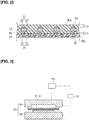
- a composite material 10 comprises a base layer 20 including a first reinforcing base material 22 and a first resin 23, and a front surface layer 30 including a second reinforcing base material 32 and a second resin 33, integrally formed on at least a portion of the surface of the base layer 20, as illustrated in Figures 1A, 1B, 1C and 2 .
- the base layer 20 comprises a first prepreg sheet 21 in which the first reinforcing base material 22 is impregnated with the first resin 23.
- the front surface layer 30 comprises a second prepreg sheet 31 in which the second reinforcing base material 32 is impregnated with the second resin 33.
- the first resin 23 in the first prepreg sheet 21 is in an uncured or semi-cured state.
- the second resin 33 in the second prepreg sheet 31 is in an uncured or semi-cured state.
- the second prepreg sheet 31 is stacked on at least a portion of the surface of the first prepreg sheet 21, and the first prepreg sheet 21 and the second prepreg sheet 31, which are stacked, are heated and cured.
- the composite material 10 is formed by integrating the front surface layer 30 on the surface of the base layer 20.
- the base layer 20 is formed by stacking a plurality of the first prepreg sheets 21, and the front surface layer 30 is formed by one of the second prepreg sheets 31.
- the first resin 23 is referred to as the "base material resin 23" and the second resin 33 is referred to as the "coating resin 33.”
- the coating resin 33 of the front surface layer 30 is present in the interface 40 within a range that is larger than a range in which the base material resin 23 of the base layer 20 is present in the interface 40 with respect to a cross section in which the base layer 20 and the front surface layer 30 are stacked. Focusing on the rectangular ranges indicated by the broken line, showing the unit volumes V1, V2, the area occupied by the coating resin 33 is greater than the area occupied by the base material resin 23.
- the amount of the coating resin 33 in the front surface layer 30 is larger than the amount of the base material resin 23 in the base layer 20 per unit volume V1, V2 in the interface 40 between the base layer 20 and the front surface layer 30" as described above.
- the second prepreg sheet 31 before molding it can be said that "when stacked on the first prepreg sheet 21, the amount of the coating resin 33 in the second prepreg sheet 31 is larger than the amount of the base material resin 23 in the first prepreg sheet 21 per unit volume V1, V2 in the interface 40 between the first prepreg sheet 21 and the second prepreg sheet 31," as described above.
- the reinforcing base material that is applied to the composite material 10 can be formed from, for example, carbon fiber, glass fiber, aramid fiber, polyamide (PA) fiber, polypropylene (PP) fiber, and acrylic fiber.
- Carbon fiber is characterized by a low coefficient of thermal expansion, excellent dimensional stability, and little degradation of mechanical properties even at high temperatures, and thus is suitably used as the first reinforcing base material 22 of the composite material 10 for an automobile vehicle body 400 (refer to Figure 9B ).
- a woven fabric material 12 obtained by weaving fabrics vertically and horizontally into a plain weave or a twill weave (refer to Figure 8A ), or a unidirectional material 13 in which fibers are aligned in one direction (refer to the left-hand drawing in Figure 6A ) as the first reinforcing base material 22 that is applied to the first prepreg sheet 21 and the second reinforcing base material 32 that is applied to the second prepreg sheet 31.
- the unidirectional material 13 is used as the first reinforcing base material 22, as illustrated in Figures 1A and 1B .
- a woven fabric material 12 in which fibers are woven is used as the second reinforcing base material 32, as illustrated in Figures 1A and 1C .
- thermosetting resin or a thermoplastic resin is used as the base material resin 23, in accordance with the desired material properties.
- a thermosetting resin or a thermoplastic resin is used as the coating resin 33, in accordance with the desired material properties.
- thermosetting resin such as epoxy resin, phenol resin, or the like
- an epoxy resin that has excellent mechanical properties and dimensional stability is used.
- the epoxy resin typically used is a two-component type, which is used by mixing a main agent and a curing agent.
- a bisphenol A type epoxy resin is used as the main agent and an amine type is used as the curing agent, but no limitation is imposed thereby, and the agents may be appropriately selected according to the desired material properties.
- thermoplastic resin such as polypropylene (PP) resin, ABS resin, or the like, is used as the coating resin 33.
- thermoplastic resin has superior impact resistance compared to thermosetting resin. Chipping occurs in the outer panel components for automobiles, which is damage caused by an impact from a flying stone that is thrown up while the automobile is traveling. Due to the superior impact resistance, as compared to a composite material in which the front surface layer is formed of a thermosetting resin, it is possible to reduce the damage caused by chipping. Additionally, since the thermoplastic resin also suppresses crack propagation better than the thermosetting resin, it is possible to suppress the deterioration in the appearance quality when used for a long period of time.
- the amount of the coating resin 33 in the region between the surface 30a and the second reinforcing base material 32 that faces the surface 30a is larger than the amount of the coating resin 33 in the region between the interface 40 with the base layer 20 and the second reinforcing base material 32 that faces the interface 40.
- an average distance La from the surface 30a to the second reinforcing base material 32 that faces the surface 30a is greater than an average distance Lb from the interface 40 to the second reinforcing base material 32 that faces the interface 40 with respect to the cross section of the front surface layer 30. If the cross section of the front surface layer 30 is in such a state, it can be said that "the amount of the coating resin 33 in the region between the surface 30a and the second reinforcing base material 32 that faces the surface 30a is larger than the amount of the coating resin 33 in the region between the interface 40 with the base layer 20 and the second reinforcing base material 32 that faces the interface 40," as described above.
- the amount of the coating resin 33 in the region between the outermost surface 30a and the second reinforcing base material 32 is larger than the amount of the coating resin 33 in the region between a rear surface 30b of the second prepreg sheet 31 and the second reinforcing base material 32," as described above.
- the front surface layer 30 is not a layer that contributes to the product strength, it is possible to create a state in which the resin content on the surface 30a side of the second prepreg sheet 31 is relatively high, that is, a so-called resin-rich state, by appropriately adjusting the amount of the coating resin 33 in the region between the outermost surface 30a and the second reinforcing base material 32.
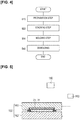
- a molding device 100 comprises a molding die 160 and a control unit 150 that controls the operation of the entire molding device 100.
- the molding die 160 includes an upper die 161 (movable type) and a lower die 162 (fixed type), forming a pair that can be opened and closed, and a temperature adjustment unit 163 that adjusts the temperature of the upper die 161 and/or the lower die 162.
- the temperature adjustment unit 163 heats the molding die 160 to a curing temperature of the base material resin 23 and to a softening temperature of the coating resin 33, heats the stacked first prepreg sheet 21 and second prepreg sheet 31, and cures the base material resin 23 of the first prepreg sheet 21.
- the temperature adjustment unit 163 is composed of the upper die 161, a heating medium such as oil or water that circulates inside the lower die 162, and an electric heater that heats the heating medium.
- the control unit 150 is composed of a memory composed of a ROM and a RAM, a CPU, and the like, and is electrically connected to the drive system of the molding die 160, the temperature adjustment unit 163, and the like, to control the operation of the entire molding device 100.
- the resin is not injected from the outside as in the RTM molding method.
- a prepreg sheet is used in all the layers, the flow of the resin inside the stacked body of prepreg sheets is relatively small, even when the resin starts to melt after placing the material inside the metal mold. Accordingly, in the case of a component for which a good appearance quality is not required, this composite material can be used without any problem.
- the flow of the resin is relatively small, there is still a slight flow of resin.
- the composite material is formed in the following manner by means of the hot press forming method.
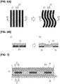
- the molding method for the composite material 10 comprises a preparation step (Step S10), a stacking step (Step S20), a molding step (Step S30), and demolding (Step S40), as illustrated in Figure 4 . Each step will be described in detail below.
- the first prepreg sheet 21 in which the first reinforcing base material 22 is impregnated with the base material resin 23 and the second prepreg sheet 31 in which the second reinforcing base material 32 is impregnated with the coating resin 33 are prepared.
- the amount of the coating resin 33 in the second prepreg sheet 31 is larger than the amount of the base material resin 23 in the first prepreg sheet 21, per unit volume V1, V2 including the interface 40 between the first prepreg sheet 21 and the second prepreg sheet 31.
- the resin content in the second prepreg sheet 31 is, for example, 50-75 wt%.
- the first reinforcing base material 22 is made of long carbon fibers, and the unidirectional material 13 is used.
- the second reinforcing base material 32 is made of glass fiber, and the woven fabric material 12 is used.
- the base material resin 23 is a thermosetting resin and the coating resin 33 is a thermoplastic resin.
- the second prepreg sheet 31 of the outermost surface the surface 30a side is brought into the so-called resin-rich state.
- the surface 30a of the front surface layer 30 is the "surface of the second prepreg sheet 31 of the outermost surface” as well as the "outermost surface.”
- Step S20 a plurality of the first prepreg sheets 21 are stacked, and the second prepreg sheet 31 is stacked on at least a portion (upper surface in the drawing) of the surface of the first prepreg sheet 21.
- the stacked first prepreg sheet 21 and second prepreg sheet 31 are placed on the lower die 162 of the molding die 160.
- the molding die 160 is pre-heated to a prescribed temperature by means of the temperature adjustment unit 163.
- the upper die 161 of the molding die 160 is closed and the stacked first and second prepreg sheets 21, 31 are subjected to hot press forming, as illustrated in Figure 5 .
- the upper die 161 and the lower die 162 are heated to the curing temperature of the base material resin 23 by means of the temperature adjustment unit 163 to thereby cure the base material resin 23 of the first prepreg sheet 21.
- the front surface layer 30 defined by the second prepreg sheet 31 is thereby integrally formed on the surface of the base layer 20 defined by the first prepreg sheet 21.
- Step S40 the upper die 161 of the molding die 160 is opened and the composite material 10 is demolded from the molding die 160, thereby completing the molding.
- the second prepreg sheet 31 is stacked on at least a portion of the surface of the first prepreg sheet 21, the first prepreg sheet 21 and the second prepreg sheet 31, which are stacked, are heated and cured, and the front surface layer 30 defined by the second prepreg sheet 31 is integrally formed on the surface of the base layer 20 defined by the first prepreg sheet 21.
- the amount of the coating resin 33 in the second prepreg sheet 31 is larger than the amount of the base material resin 23 in the first prepreg sheet 21, per unit volume V1, V2, including the interface 40 between the first prepreg sheet 21 and the second prepreg sheet 31.
- the hot press forming using the first and second prepreg sheets 21, 31 is carried out in the molding step.
- the first prepreg sheet 21 constituting the base layer 20 is already impregnated with the base material resin 23, so it is possible to suppress the coating resin 33 from immediately flowing into the first prepreg sheet 21 from the second prepreg sheet 31 constituting the front surface layer 30. It is possible to suppress wrinkles and kinks that occur due to the coating resin 33 and the base material resin 23 flowing together, and to suppress irregularities on the surface 30a of the front surface layer 30, which are formed by the first reinforcing base material 22 being impregnated with the coating resin 33. In this manner, since the surface 30a of the front surface layer 30 can be smoothed, it is possible to improve the appearance quality of the composite material 10.
- the second reinforcing base material sucks up the base material resin. Accordingly, internal voids are generated in the first prepreg sheet, which may cause a decrease in the strength of the base layer.
- the amount of the coating resin 33 in the second prepreg sheet 31 is set to be larger than the amount of the base material resin 23 in the first prepreg sheet 21, per unit volume V1, V2, including the interface 40 between the first prepreg sheet 21 and the second prepreg sheet 31. Accordingly, the second reinforcing base material 32 does not suck up the base material resin 23, and internal voids are not generated in the first prepreg sheet 21. It is thereby possible to improve the appearance quality of the composite material 10 and to prevent a reduction in the strength of the base layer 20.
- the front surface layer 30 is not a layer that contributes to the product strength, it is possible to impart luster to the surface 30a and to further improve the appearance quality of the composite material 10, by appropriately adjusting the amount of the coating resin 33 in the second prepreg sheet 31.
- the amount of the coating resin 33 in the second prepreg sheet 31 is larger than the amount of the base material resin 23 in the first prepreg sheet 21, it is thought that perhaps the coating resin 33 flows into the first prepreg sheet 21, causing a so-called resin depletion and leading to deterioration of the appearance.
- both the base layer 20 and the front surface layer 30 are composed of prepreg sheets, the difference in the resin density between the first prepreg sheet 21 and the second prepreg sheet 31 is relatively small. Accordingly, it is thought that there is relatively little movement of the resin from the front surface layer 30 to the base layer 20.
- the coating resin 33 were to move to the base layer 20, it would suffice to impregnate the second prepreg sheet 31 with a sufficiently additional amount of resin to allow for any resin that might move.
- the so-called resin depletion does not occur in the second prepreg sheet 31, and deterioration in the appearance of the surface 30a does not occur.
- the composite material 10 is formed of the first and second prepreg sheets 21, 31, which include the reinforcing base materials 22, 32 and the resins 23, 33 in the uncured or semi-cured state.
- the unidirectional material 13 can be used; therefore, it is possible to expand the range of selectable fiber orientations.
- the second reinforcing base material 32 is made of glass fiber. By using glass fiber as the reinforcing fiber, as compared to a case in which carbon fiber is used, it is possible to inexpensively form the second reinforcing base material 32, and to also inexpensively form the composite material 10.
- the base material resin 23 is softened by the heat and flows between the fibers of the first reinforcing base material 22.
- the unidirectional material 13 obtained by arranging, in the same direction, a plurality of fiber bundles 22a, in which a plurality of fibers are bundled, were disposed on the outermost layer of the first prepreg sheet 21, the unidirectional material 13 would have a weaker binding force in a direction orthogonal to the orientation direction of the fibers. As a result, even a slight flow of the base material resin 23 easily disturbs the orientation of the fibers, as illustrated in the right-hand drawing of Figure 6A .
- the second reinforcing base material 32 is the woven fabric material 12 in which fibers are woven.
- the second reinforcing base material 32 made of the woven fabric material 12, crosses the first reinforcing base material 22 and presses the first reinforcing base material 22, as illustrated in Figure 7 .
- the unidirectional material 13 is disposed as the first reinforcing base material 22
- the fiber orientation can be better controlled compared to a case in which nonwoven fabric is used; therefore, variation in the thickness of the second reinforcing base material 32 can be reduced. From this point of view as well, it is possible to obtain a smoother surface 30a of the front surface layer 30, and to improve the appearance quality of the composite material 10.
- the front surface layer 30 is not a layer that contributes to the product strength, it is possible to make the basis weight of the woven fabric material 12 relatively small, as illustrated in Figure 8A . Accordingly, air bubbles are not likely to remain where the fiber bundles 22a intersect, so it is possible to suppress the occurrence of minute irregularities on the surface 30a of the composite material 10 and to improve the appearance quality of the composite material 10.
- the coating resin 33 is the thermoplastic resin.
- the thermoplastic resin By disposing the thermoplastic resin, as opposed to the thermosetting resin, on the outermost layer of the composite material 10, it is possible to form a composite material 10 having superior impact resistance.
- it is possible to suppress interlaminar separation and crack propagation caused by chipping, etc. it is possible to suppress the deterioration in the appearance quality when the outer panel component, to which the composite material 10 is applied, is used for a long period of time.
- the coating resin 33 which is the thermoplastic resin, is softened.
- the melted coating resin 33 enters into the irregularities on the surface of the base layer 20.
- the surface 30a becomes smooth by means of the coating resin 33 filling in the irregularities formed on the surface of the base layer 20. It is thereby possible to eliminate the irregularities on the surface of the base layer 20, to smoothen the surface 30a of the front surface layer 30, and to improve the appearance quality of the composite material 10 after painting.
- the base material resin 23 is made of the thermosetting resin and the coating resin 33 is made of the thermoplastic resin, it can also be thought that the base material resin 23 and the coating resin 33 flow together, and that wrinkles and kinks tend to occur at the interface 40 between the thermoplastic resin and the thermosetting resin, due to differences in the viscosity and the thermal contraction rate between the thermoplastic resin and the thermosetting resin.
- the front surface layer 30 is not a layer that contributes to the product strength, it is possible to appropriately adjust the amount of the coating resin 33 in the second prepreg sheet 31.
- the base material resin 23 is made of the thermosetting resin and the coating resin 33 is made of the thermoplastic resin, it is possible to suppress the irregularities from being formed on the surface 30a of the composite material 10, and the appearance quality of the composite material 10 will not be deteriorated.
- the amount of the coating resin 33 in the region between the outermost surface 30a and the second reinforcing base material 32 is larger than the amount of the coating resin 33 in the region between the rear surface 30b of the second prepreg sheet 31 and the second reinforcing base material 32.
- the front surface layer 30 is not a layer that contributes to the product strength, it is possible to bring the surface 30a side of the second prepreg sheet 31 into the so-called resin-rich state. By bringing the surface 30a side into the resin-rich state, it is possible to prevent irregularities on the surface 30a from being generated, and to further impart luster to the surface 30a. The appearance quality is thus improved.
- the first reinforcing base material 22 is made of long carbon fibers. It is easier to make the fiber orientation uniform, as compared to a case in which short fibers are used, and in which the fiber orientations are random. Accordingly, it is possible to suppress wrinkles and kinks caused by the disturbance in the fibers, and to suppress the irregularities on the surface of the base layer 20. As a result, the appearance quality of the composite material 10 can be improved.
- the first reinforcing base material 22 is the unidirectional material 13, in which the fibers are aligned in one direction. Because the fiber used for the first reinforcing base material 22 is the unidirectional material 13, the irregularities that appear on the surface of the base layer 20 decrease as compared to when the woven fabric material 12 is used. As a result of being able to suppress the irregularities on the surface of the base layer 20, it is possible to improve the appearance quality of the composite material 10.
- the base material resin 23 is the thermosetting resin.
- the thermosetting resin has higher heat resistance and superior dimensional stability than the thermoplastic resin. Therefore, it is possible to form the composite material 10 with high heat resistance and superior dimensional stability.
- the composite material 10 comprises the base layer 20 including the first reinforcing base material 22 and the base material resin 23, and the front surface layer 30 including the second reinforcing base material 32 and the coating resin 33, integrally formed on at least a portion of the surface of the base layer 20.
- the amount of the second resin 33 in the front surface layer 30 is larger than the amount of the first resin 23 in the base layer 20, per unit volume V1, V2, including the interface 40 between the base layer 20 and the front surface layer 30.
- the composite material 10 configured in this manner, wrinkles and kinks that occur due to the coating resin 33 and the base material resin 23 flowing together are suppressed, and irregularities, which are formed by the first reinforcing base material 22 being impregnated with the coating resin 33, are not generated on the surface 30a of the front surface layer 30. In this manner, since the surface 30a of the front surface layer 30 is smooth, it is possible to provide the composite material 10 with an improved appearance quality.
- the front surface layer 30 is not a layer that contributes to the product strength, it is possible to impart luster to the surface 30a and to provide the composite material 10 with a further improved appearance quality, by appropriately adjusting the amount of the coating resin 33.
- the ranges in which the coating resin 33 of the front surface layer 30 is present on the interface 40 in a cross section of the stacked base layer 20 and front surface layer 30 are larger than the ranges in which the first resin 23 of the base layer 20 is present on the interface 40, as illustrated in Figure 2 .
- the cross section of the stacked base layer 20 and the front surface layer 30 is in such a state, it can be considered that in the composite material 10, "the amount of the coating resin 33 in the front surface layer 30 is larger than the amount of the base material resin 23 in the base layer 20, per unit volume V1, V2, including the interface 40 between the base layer 20 and the front surface layer 30.”
- the second prepreg sheet 31 before molding it can be considered that "when stacked on the first prepreg sheet 21, the amount of the coating resin 33 in the second prepreg sheet 31 is larger than the amount of the base material resin 23 in the first prepreg sheet 21, per unit volume V1, V2, including the interface 40 between the first prepreg sheet 21 and the second prepreg sheet 31.”
- the average distance La from the surface 30a to the second reinforcing base material 32 that faces the surface 30a is greater than the average distance Lb from the interface 40 to the second reinforcing base material 32 that faces the interface 40. If the cross section of the front surface layer 30 is in such a state, it can be considered that in the composite material 10 "the amount of the coating resin 33 in the region between the surface 30a and the second reinforcing base material 32 that faces the surface 30a is larger than the amount of the coating resin 33 in the region between the interface 40 with the base layer 20 and the second reinforcing base material 32 that faces the interface 40.” Furthermore, regarding the second prepreg sheet 31 before molding, it can be said that "the amount of the coating resin 33 in the region between the outermost surface 30a and the second reinforcing base material 32 is larger than the amount of the coating resin 33 in the region between a rear surface 30b of the second prepreg sheet 31 and the second reinforcing base material 32.”
- the base material resin 23 constituting the base layer 20 is not limited to the thermosetting resin, and the thermoplastic resin may be used.
- the molded body can be formed by closing the molding die 160 in a state in which the base material resin 23, which is the thermoplastic resin, is heated and softened, and then cooled to be cured.
- the coating resin 33 constituting the front surface layer 30 is not limited to the thermoplastic resin, and the thermosetting resin may be used.
- the stacked structure of the first prepreg sheet 21 and the second prepreg sheet 31 is not limited to the above-described embodiment.
- a mode was shown in which the second prepreg sheet 31 is stacked only on one side surface of the first prepreg sheet 21, but the second prepreg sheet 31 may be stacked on both side surfaces of the first prepreg sheet 21, and form the composite material 10 in which the front surface layer 30 is formed on both side surfaces of the base layer 20.
Landscapes
- Engineering & Computer Science (AREA)
- Mechanical Engineering (AREA)
- Textile Engineering (AREA)
- Chemical & Material Sciences (AREA)
- Composite Materials (AREA)
- Physics & Mathematics (AREA)
- Mathematical Physics (AREA)
- Casting Or Compression Moulding Of Plastics Or The Like (AREA)
- Laminated Bodies (AREA)
- Reinforced Plastic Materials (AREA)
- Moulding By Coating Moulds (AREA)
Abstract
Description
- The present invention relates to a molding method for composite materials and a composite material.
- In recent years, composite materials made by impregnating a reinforcing base material with resin have been used as automobile parts to reduce automobile body weight. Particularly among automobile parts, outer panel components such as roofs and hoods are required to have high appearance quality.
- When molding composite materials in which a resin is cured and shrinks, fine irregularities may form on the surface due to a difference in a shrinkage ratio between the resin and a reinforcing base material. The fine irregularities on the surface cause deterioration in the appearance quality after painting.
- For example, a method disclosed in the following
Patent Document 1 is known as a method for eliminating the irregularities on the surface of the composite material. According to this method, a dry base material in which a reinforcing base material is not impregnated with resin is used as an intermediate layer, and this intermediate layer is sandwiched between prepreg sheets in which a reinforcing base material is impregnated with resin, after which resin is injected to carry out RTM molding. Attempts have been made to eliminate surface irregularities by preventing the resin in the prepreg sheets from flowing out from the prepreg sheets toward the intermediate layer, when the resin with which the intermediate layer is impregnated is cured and shrinks. - Patent Document 1: Japanese Laid Open Patent Application No.
2010-221489 - However, in the method according to
Patent Document 1, since the temperature of the metal mold is high in order to carry out molding, when a material is placed in the metal mold, the resin immediately starts to melt. Because the intermediate layer is a dry base material that is not impregnated with resin, the resin with which the prepreg sheets of the surface layers are impregnated immediately melts and starts to flow toward the intermediate layer. The flow of the resin causes disturbance in the reinforcing fibers. As a result, internal voids as well as wrinkles and kinks of the fibers occur, which may cause a deterioration in the appearance quality of the composite material. - Moreover, in the method according to
Patent Document 1, use of the RTM molding method is assumed. In the RTM molding method, the resin is injected into the metal mold from an injection gate, so there is already a flow of resin; therefore, the method likely causes the disturbance in the reinforcing fibers. - In order to solve the problem described above, an object of the present invention is to provide a molding method for a composite material and a composite material with which it is possible to eliminate irregularities on the surface of the composite material to improve the appearance quality.
- In the molding method for a composite material according to the present invention, which achieves the object described above, first, a first reinforcing base material is impregnated with a first resin to prepare a first prepreg sheet that constitutes a base layer, and a second reinforcing base material is impregnated with a second resin to prepare a second prepreg sheet that constitutes a front surface layer. Here, when the second prepreg sheet is stacked on the first prepreg sheet, the amount of the second resin in the second prepreg sheet is larger than the amount of the first resin in the first prepreg sheet, per unit volume, including the interface between the first prepreg sheet and the second prepreg sheet. Then, the second prepreg sheet is stacked on at least a portion of the surface of the first prepreg sheet, and the first prepreg sheet and the second prepreg sheet, which are stacked, are heated and cured. The front surface layer defined by the second prepreg sheet is thereby integrally formed on a surface of the base layer defined by the first prepreg sheet.
- In addition, the composite material according to the present invention, which achieves the object described above, comprises a base layer including a first reinforcing base material and a first resin, and a front surface layer including a second reinforcing base material and a second resin, integrally formed on at least a portion of the surface of the base layer. Here, the amount of the second resin in the front surface layer is larger than the amount of the first resin in the base layer, per unit volume, including the interface between the base layer and the front surface layer.
-
- [
Figure 1A ] is a schematic cross-sectional view illustrating a configuration of a composite material according to the present embodiment. - [
Figure 1B ] is a schematic cross-sectional view illustrating the configuration of a first prepreg sheet. - [
Figure 1C ] is a schematic cross-sectional view illustrating the configuration of a second prepreg sheet. - [
Figure 2 ] is a cross-sectional view illustrating a main part of a composite material. - [
Figure 3 ] is a schematic view illustrating a molding device for composite materials. - [
Figure 4 ] is a flow chart illustrating the molding method for a composite material. - [
Figure 5 ] is a view for explaining a procedure for molding a composite material using the molding device for composite materials, and a schematic view illustrating a molding step. - [
Figure 6A ] is a view illustrating a state in which the composite material is molded, and a schematic view illustrating before (left-hand) and after (right-hand) the resin is cured when molding a composite material having a unidirectional material as the outermost layer. - [
Figure 6B ] is a partial cross-sectional view (left-hand) taken along the line A1-A1 line of the left-hand-hand drawing shown inFigure 6A and a partial cross-sectional view (right-hand) taken along the line A2-A2 line of the right-hand-hand drawing shown inFigure 6A . - [
Figure 7 ] is a partial cross-sectional view illustrating a state in which a second reinforcing base material, made of a woven fabric material, is pressing a first reinforcing base material. - [
Figure 8A ] is a plan view illustrating the second reinforcing base material, made of a woven fabric material. - [
Figure 8B ] is a plan view illustrating the second reinforcing base material in a case in which the basis weight of the woven fabric material (fabric weight per unit area (g/m2)) is relatively large. - [
Figure 9A ] is a view illustrating application examples of composite material that is molded by means of the molding method in accordance with the embodiment, and a view illustrating various automobile parts that use the composite material. - [
Figure 9B ] is a view illustrating application examples of composite material that is molded by means of the molding method in accordance with the embodiment, and a view illustrating a vehicle body that is formed by joining the various automobile parts that use the composite material. - Embodiments of the present invention will be explained below with reference to the appended drawings. The description below does not limit the technical scopes or the meanings of the terms described in the Claims. Dimensional ratios in the drawings are exaggerated for the sake of convenience of explanation and may differ from actual ratios.
- As is well known, a composite material has a reinforcing base material and a resin. The composite material is provided with a greater strength than resin alone by combining the resin with the reinforcing base material. The composite material is applied to outer panel components such as a
roof 401 and ahood 402 of anautomobile vehicle body 400, as illustrated inFigures 9A and 9B . By means of applying the composite material, a greater reduction in the weight of thevehicle body 400 becomes possible as compared to a case in which a steel material is used. - In general, a
composite material 10 according to the present embodiment comprises abase layer 20 including a first reinforcingbase material 22 and afirst resin 23, and afront surface layer 30 including a second reinforcingbase material 32 and asecond resin 33, integrally formed on at least a portion of the surface of thebase layer 20, as illustrated inFigures 1A, 1B, 1C and2 . In thiscomposite material 10, aninterface 40 between thebase layer 20 and thefront surface layer 30 is set so that an amount of thesecond resin 33 in thefront surface layer 30 per unit volume V2 is larger than an amount of thefirst resin 23 in thebase layer 20 per unit volume V1 (V1 = V2). - The
base layer 20 comprises afirst prepreg sheet 21 in which the first reinforcingbase material 22 is impregnated with thefirst resin 23. Thefront surface layer 30 comprises asecond prepreg sheet 31 in which the second reinforcingbase material 32 is impregnated with thesecond resin 33. Here, when thesecond prepreg sheet 31 is stacked on thefirst prepreg sheet 21, theinterface 40 between thefirst prepreg sheet 21 and thesecond prepreg sheet 31 is set so that the amount of thesecond resin 33 in thesecond prepreg sheet 31 per unit volume V2 is larger than the amount of thefirst resin 23 in thefirst prepreg sheet 21 per unit volume V1 (V1 = V2). Thefirst resin 23 in thefirst prepreg sheet 21 is in an uncured or semi-cured state. Similarly, thesecond resin 33 in thesecond prepreg sheet 31 is in an uncured or semi-cured state. Thesecond prepreg sheet 31 is stacked on at least a portion of the surface of thefirst prepreg sheet 21, and thefirst prepreg sheet 21 and thesecond prepreg sheet 31, which are stacked, are heated and cured. Thecomposite material 10 is formed by integrating thefront surface layer 30 on the surface of thebase layer 20. In the illustrated example, thebase layer 20 is formed by stacking a plurality of thefirst prepreg sheets 21, and thefront surface layer 30 is formed by one of thesecond prepreg sheets 31. In the following description, thefirst resin 23 is referred to as the "base material resin 23" and thesecond resin 33 is referred to as the "coating resin 33." - Referring to
Figure 2 , thecoating resin 33 of thefront surface layer 30 is present in theinterface 40 within a range that is larger than a range in which the base material resin 23 of thebase layer 20 is present in theinterface 40 with respect to a cross section in which thebase layer 20 and thefront surface layer 30 are stacked. Focusing on the rectangular ranges indicated by the broken line, showing the unit volumes V1, V2, the area occupied by thecoating resin 33 is greater than the area occupied by thebase material resin 23. If the cross section of thestacked base layer 20 and thefront surface layer 30 is in such a state, it is possible to say that " the amount of thecoating resin 33 in thefront surface layer 30 is larger than the amount of thebase material resin 23 in thebase layer 20 per unit volume V1, V2 in theinterface 40 between thebase layer 20 and thefront surface layer 30" as described above. Moreover, as concerns thesecond prepreg sheet 31 before molding, it can be said that "when stacked on thefirst prepreg sheet 21, the amount of thecoating resin 33 in thesecond prepreg sheet 31 is larger than the amount of thebase material resin 23 in thefirst prepreg sheet 21 per unit volume V1, V2 in theinterface 40 between thefirst prepreg sheet 21 and thesecond prepreg sheet 31," as described above. - The reinforcing base material that is applied to the
composite material 10 can be formed from, for example, carbon fiber, glass fiber, aramid fiber, polyamide (PA) fiber, polypropylene (PP) fiber, and acrylic fiber. - In the present embodiment, an example will be described in which long carbon fibers are used as the first reinforcing
base material 22. Carbon fiber is characterized by a low coefficient of thermal expansion, excellent dimensional stability, and little degradation of mechanical properties even at high temperatures, and thus is suitably used as the first reinforcingbase material 22 of thecomposite material 10 for an automobile vehicle body 400 (refer toFigure 9B ). - An example will be described in which glass fiber is used as the second reinforcing
base material 32. - It is possible to use a
woven fabric material 12 obtained by weaving fabrics vertically and horizontally into a plain weave or a twill weave (refer toFigure 8A ), or aunidirectional material 13 in which fibers are aligned in one direction (refer to the left-hand drawing inFigure 6A ) as the first reinforcingbase material 22 that is applied to thefirst prepreg sheet 21 and the second reinforcingbase material 32 that is applied to thesecond prepreg sheet 31. - In the present embodiment, the
unidirectional material 13 is used as the first reinforcingbase material 22, as illustrated inFigures 1A and 1B . In addition, awoven fabric material 12 in which fibers are woven is used as the second reinforcingbase material 32, as illustrated inFigures 1A and 1C . Thesecond prepreg sheet 31 including the second reinforcingbase material 32, which is the wovenfabric material 12, presses against thefirst prepreg sheet 21 including the first reinforcingbase material 22 at the time of molding. - A thermosetting resin or a thermoplastic resin is used as the
base material resin 23, in accordance with the desired material properties. Similarly, a thermosetting resin or a thermoplastic resin is used as thecoating resin 33, in accordance with the desired material properties. - In the present embodiment, a thermosetting resin such as epoxy resin, phenol resin, or the like, is used as the
base material resin 23. In the present embodiment, an epoxy resin that has excellent mechanical properties and dimensional stability is used. The epoxy resin typically used is a two-component type, which is used by mixing a main agent and a curing agent. Generally, a bisphenol A type epoxy resin is used as the main agent and an amine type is used as the curing agent, but no limitation is imposed thereby, and the agents may be appropriately selected according to the desired material properties. - In the present embodiment, a thermoplastic resin such as polypropylene (PP) resin, ABS resin, or the like, is used as the
coating resin 33. - In general, thermoplastic resin has superior impact resistance compared to thermosetting resin. Chipping occurs in the outer panel components for automobiles, which is damage caused by an impact from a flying stone that is thrown up while the automobile is traveling. Due to the superior impact resistance, as compared to a composite material in which the front surface layer is formed of a thermosetting resin, it is possible to reduce the damage caused by chipping. Additionally, since the thermoplastic resin also suppresses crack propagation better than the thermosetting resin, it is possible to suppress the deterioration in the appearance quality when used for a long period of time.
- Regarding the
front surface layer 30, the amount of thecoating resin 33 in the region between thesurface 30a and the second reinforcingbase material 32 that faces thesurface 30a is larger than the amount of thecoating resin 33 in the region between theinterface 40 with thebase layer 20 and the second reinforcingbase material 32 that faces theinterface 40. - Referring to
Figure 2 , , an average distance La from thesurface 30a to the second reinforcingbase material 32 that faces thesurface 30a is greater than an average distance Lb from theinterface 40 to the second reinforcingbase material 32 that faces theinterface 40 with respect to the cross section of thefront surface layer 30. If the cross section of thefront surface layer 30 is in such a state, it can be said that "the amount of thecoating resin 33 in the region between thesurface 30a and the second reinforcingbase material 32 that faces thesurface 30a is larger than the amount of thecoating resin 33 in the region between theinterface 40 with thebase layer 20 and the second reinforcingbase material 32 that faces theinterface 40," as described above. Furthermore, regarding thesecond prepreg sheet 31 before molding, it can be said that "the amount of thecoating resin 33 in the region between theoutermost surface 30a and the second reinforcingbase material 32 is larger than the amount of thecoating resin 33 in the region between arear surface 30b of thesecond prepreg sheet 31 and the second reinforcingbase material 32," as described above. - Since the
front surface layer 30 is not a layer that contributes to the product strength, it is possible to create a state in which the resin content on thesurface 30a side of thesecond prepreg sheet 31 is relatively high, that is, a so-called resin-rich state, by appropriately adjusting the amount of thecoating resin 33 in the region between theoutermost surface 30a and the second reinforcingbase material 32. - Referring to
Figure 3 , a molding device 100 according to the present embodiment comprises amolding die 160 and acontrol unit 150 that controls the operation of the entire molding device 100. - The molding die 160 includes an upper die 161 (movable type) and a lower die 162 (fixed type), forming a pair that can be opened and closed, and a
temperature adjustment unit 163 that adjusts the temperature of theupper die 161 and/or thelower die 162. - The
temperature adjustment unit 163 heats the molding die 160 to a curing temperature of thebase material resin 23 and to a softening temperature of thecoating resin 33, heats the stackedfirst prepreg sheet 21 andsecond prepreg sheet 31, and cures thebase material resin 23 of thefirst prepreg sheet 21. For example, thetemperature adjustment unit 163 is composed of theupper die 161, a heating medium such as oil or water that circulates inside thelower die 162, and an electric heater that heats the heating medium. - The
control unit 150 is composed of a memory composed of a ROM and a RAM, a CPU, and the like, and is electrically connected to the drive system of the molding die 160, thetemperature adjustment unit 163, and the like, to control the operation of the entire molding device 100. - The molding method for a
composite material 10 will be described below. - In the case of a hot press forming method using prepreg sheets, the resin is not injected from the outside as in the RTM molding method. In addition, since a prepreg sheet is used in all the layers, the flow of the resin inside the stacked body of prepreg sheets is relatively small, even when the resin starts to melt after placing the material inside the metal mold. Accordingly, in the case of a component for which a good appearance quality is not required, this composite material can be used without any problem. However, although the flow of the resin is relatively small, there is still a slight flow of resin. When there is a required appearance quality for the composite material, such as when applying a paint in a subsequent step, disturbance in the fibers caused by even a slight flow of the resin causes deterioration in the appearance quality. Accordingly, in the present embodiment, the composite material is formed in the following manner by means of the hot press forming method.
- The molding method for the
composite material 10 comprises a preparation step (Step S10), a stacking step (Step S20), a molding step (Step S30), and demolding (Step S40), as illustrated inFigure 4 . Each step will be described in detail below. - In the preparation step (Step S10), as shown in
Figures 1B and 1C , thefirst prepreg sheet 21 in which the first reinforcingbase material 22 is impregnated with thebase material resin 23 and thesecond prepreg sheet 31 in which the second reinforcingbase material 32 is impregnated with thecoating resin 33 are prepared. Here, when thesecond prepreg sheet 31 is stacked on thefirst prepreg sheet 21, the amount of thecoating resin 33 in thesecond prepreg sheet 31 is larger than the amount of thebase material resin 23 in thefirst prepreg sheet 21, per unit volume V1, V2 including theinterface 40 between thefirst prepreg sheet 21 and thesecond prepreg sheet 31. While not particularly limited, the resin content in thesecond prepreg sheet 31 is, for example, 50-75 wt%. - As described above, in the present embodiment, the first reinforcing
base material 22 is made of long carbon fibers, and theunidirectional material 13 is used. The second reinforcingbase material 32 is made of glass fiber, and the wovenfabric material 12 is used. Thebase material resin 23 is a thermosetting resin and thecoating resin 33 is a thermoplastic resin. Moreover, regarding thesecond prepreg sheet 31 of the outermost surface, thesurface 30a side is brought into the so-called resin-rich state. In the embodiment, only one of thesecond prepreg sheets 31 is used, so thissecond prepreg sheet 31 corresponds to the "second prepreg sheet of the outermost surface." Accordingly, thesurface 30a of thefront surface layer 30 is the "surface of thesecond prepreg sheet 31 of the outermost surface" as well as the "outermost surface." - In the stacking step (Step S20), a plurality of the
first prepreg sheets 21 are stacked, and thesecond prepreg sheet 31 is stacked on at least a portion (upper surface in the drawing) of the surface of thefirst prepreg sheet 21. - In the molding step (Step S30), the stacked
first prepreg sheet 21 andsecond prepreg sheet 31 are placed on the lower die 162 of the molding die 160. The molding die 160 is pre-heated to a prescribed temperature by means of thetemperature adjustment unit 163. Theupper die 161 of the molding die 160 is closed and the stacked first andsecond prepreg sheets Figure 5 . Theupper die 161 and thelower die 162 are heated to the curing temperature of thebase material resin 23 by means of thetemperature adjustment unit 163 to thereby cure thebase material resin 23 of thefirst prepreg sheet 21. Thefront surface layer 30 defined by thesecond prepreg sheet 31 is thereby integrally formed on the surface of thebase layer 20 defined by thefirst prepreg sheet 21. - Finally, the
upper die 161 of the molding die 160 is opened and thecomposite material 10 is demolded from the molding die 160, thereby completing the molding (Step S40). - According to the molding method for the
composite material 10 of the present embodiment, thesecond prepreg sheet 31 is stacked on at least a portion of the surface of thefirst prepreg sheet 21, thefirst prepreg sheet 21 and thesecond prepreg sheet 31, which are stacked, are heated and cured, and thefront surface layer 30 defined by thesecond prepreg sheet 31 is integrally formed on the surface of thebase layer 20 defined by thefirst prepreg sheet 21. At this time, when thesecond prepreg sheet 31 is stacked on thefirst prepreg sheet 21, the amount of thecoating resin 33 in thesecond prepreg sheet 31 is larger than the amount of thebase material resin 23 in thefirst prepreg sheet 21, per unit volume V1, V2, including theinterface 40 between thefirst prepreg sheet 21 and thesecond prepreg sheet 31. - According to the molding method for the
composite material 10 configured in this manner, the hot press forming using the first andsecond prepreg sheets first prepreg sheet 21 constituting thebase layer 20 is already impregnated with thebase material resin 23, so it is possible to suppress thecoating resin 33 from immediately flowing into thefirst prepreg sheet 21 from thesecond prepreg sheet 31 constituting thefront surface layer 30. It is possible to suppress wrinkles and kinks that occur due to thecoating resin 33 and thebase material resin 23 flowing together, and to suppress irregularities on thesurface 30a of thefront surface layer 30, which are formed by the first reinforcingbase material 22 being impregnated with thecoating resin 33. In this manner, since thesurface 30a of thefront surface layer 30 can be smoothed, it is possible to improve the appearance quality of thecomposite material 10. - In addition, if only the second reinforcing base material is stacked on the surface of the first prepreg sheet, or if the second prepreg sheet having a smaller resin content that the first prepreg sheet is stacked, the second reinforcing base material sucks up the base material resin. Accordingly, internal voids are generated in the first prepreg sheet, which may cause a decrease in the strength of the base layer. According to the present embodiment, when the
second prepreg sheet 31 is stacked on thefirst prepreg sheet 21, the amount of thecoating resin 33 in thesecond prepreg sheet 31 is set to be larger than the amount of thebase material resin 23 in thefirst prepreg sheet 21, per unit volume V1, V2, including theinterface 40 between thefirst prepreg sheet 21 and thesecond prepreg sheet 31. Accordingly, the second reinforcingbase material 32 does not suck up thebase material resin 23, and internal voids are not generated in thefirst prepreg sheet 21. It is thereby possible to improve the appearance quality of thecomposite material 10 and to prevent a reduction in the strength of thebase layer 20. - Moreover, since the
front surface layer 30 is not a layer that contributes to the product strength, it is possible to impart luster to thesurface 30a and to further improve the appearance quality of thecomposite material 10, by appropriately adjusting the amount of thecoating resin 33 in thesecond prepreg sheet 31. - Due to the fact that the amount of the
coating resin 33 in thesecond prepreg sheet 31 is larger than the amount of thebase material resin 23 in thefirst prepreg sheet 21, it is thought that perhaps thecoating resin 33 flows into thefirst prepreg sheet 21, causing a so-called resin depletion and leading to deterioration of the appearance. However, since both thebase layer 20 and thefront surface layer 30 are composed of prepreg sheets, the difference in the resin density between thefirst prepreg sheet 21 and thesecond prepreg sheet 31 is relatively small. Accordingly, it is thought that there is relatively little movement of the resin from thefront surface layer 30 to thebase layer 20. Moreover, even if thecoating resin 33 were to move to thebase layer 20, it would suffice to impregnate thesecond prepreg sheet 31 with a sufficiently additional amount of resin to allow for any resin that might move. By configuring as above, the so-called resin depletion does not occur in thesecond prepreg sheet 31, and deterioration in the appearance of thesurface 30a does not occur. - The
composite material 10 is formed of the first andsecond prepreg sheets base materials resins unidirectional material 13 can be used; therefore, it is possible to expand the range of selectable fiber orientations. - The second reinforcing
base material 32 is made of glass fiber. By using glass fiber as the reinforcing fiber, as compared to a case in which carbon fiber is used, it is possible to inexpensively form the second reinforcingbase material 32, and to also inexpensively form thecomposite material 10. - In the molding step, until the
base material resin 23 is cured, thebase material resin 23 is softened by the heat and flows between the fibers of the first reinforcingbase material 22. As shown in the left-hand drawing ofFigure 6A , if theunidirectional material 13, obtained by arranging, in the same direction, a plurality offiber bundles 22a, in which a plurality of fibers are bundled, were disposed on the outermost layer of thefirst prepreg sheet 21, theunidirectional material 13 would have a weaker binding force in a direction orthogonal to the orientation direction of the fibers. As a result, even a slight flow of thebase material resin 23 easily disturbs the orientation of the fibers, as illustrated in the right-hand drawing ofFigure 6A . In addition, due to the orientation of the fibers being disturbed, peeling occurs at the single fiber level in thefiber bundle 22a, as illustrated in the left-hand drawing ofFigure 6B . The disturbance in the fiber orientation of the first reinforcingbase material 22 appears on the surface of thebase layer 20 as wrinkles and kinks, and causes localized deterioration in the strength. Additionally, there are cases in which localized sinks S as that shown in the right-hand drawing ofFigure 6B occur at sites where the fibers are peeled away, thereby deteriorating the appearance quality of thesurface 30a of thefront surface layer 30. - In the present embodiment, the second reinforcing
base material 32 is the wovenfabric material 12 in which fibers are woven. At the time of molding, the second reinforcingbase material 32, made of the wovenfabric material 12, crosses the first reinforcingbase material 22 and presses the first reinforcingbase material 22, as illustrated inFigure 7 . As a result, it is possible to suppress the disturbance of the fibers that occurs due to flowing of thebase material resin 23 in the portion where the wovenfabric material 12 is disposed. Even in a case in which theunidirectional material 13 is disposed as the first reinforcingbase material 22, it is possible to suppress the fibers of theunidirectional material 13 from being disturbed in the direction orthogonal to the orientation direction due to the flow of thebase material resin 23 that occurs in the molding step. Accordingly, it is possible to suppress the generation of wrinkles and kinks that occur on the surface of the outermost layer of thefirst prepreg sheet 21, and to prevent surface irregularities caused by the fibers being peeled away. As a result, irregularities do not occur on thesurface 30a of thesecond prepreg sheet 31, and it is possible to improve the appearance quality of thecomposite material 10. - Moreover, by using the woven
fabric material 12 for the second reinforcingbase material 32, the fiber orientation can be better controlled compared to a case in which nonwoven fabric is used; therefore, variation in the thickness of the second reinforcingbase material 32 can be reduced. From this point of view as well, it is possible to obtain asmoother surface 30a of thefront surface layer 30, and to improve the appearance quality of thecomposite material 10. - If the basis weight of the woven fabric material 12 (fabric weight per unit area (g/m2)) is relatively large, air bubbles tend to remain in the portions where the
fiber bundles 22a intersect (portion indicated by the broken line), as illustrated inFigure 8B , and there is the risk of minute irregularities forming on thesurface 30a of thecomposite material 10, thereby deteriorating the appearance quality. - In the present embodiment, since the
front surface layer 30 is not a layer that contributes to the product strength, it is possible to make the basis weight of the wovenfabric material 12 relatively small, as illustrated inFigure 8A . Accordingly, air bubbles are not likely to remain where thefiber bundles 22a intersect, so it is possible to suppress the occurrence of minute irregularities on thesurface 30a of thecomposite material 10 and to improve the appearance quality of thecomposite material 10. - The
coating resin 33 is the thermoplastic resin. By disposing the thermoplastic resin, as opposed to the thermosetting resin, on the outermost layer of thecomposite material 10, it is possible to form acomposite material 10 having superior impact resistance. In addition, since it is possible to suppress interlaminar separation and crack propagation caused by chipping, etc., it is possible to suppress the deterioration in the appearance quality when the outer panel component, to which thecomposite material 10 is applied, is used for a long period of time. - Moreover, the
coating resin 33, which is the thermoplastic resin, is softened. The meltedcoating resin 33 enters into the irregularities on the surface of thebase layer 20. Thesurface 30a becomes smooth by means of thecoating resin 33 filling in the irregularities formed on the surface of thebase layer 20. It is thereby possible to eliminate the irregularities on the surface of thebase layer 20, to smoothen thesurface 30a of thefront surface layer 30, and to improve the appearance quality of thecomposite material 10 after painting. - Because the
base material resin 23 is made of the thermosetting resin and thecoating resin 33 is made of the thermoplastic resin, it can also be thought that thebase material resin 23 and thecoating resin 33 flow together, and that wrinkles and kinks tend to occur at theinterface 40 between the thermoplastic resin and the thermosetting resin, due to differences in the viscosity and the thermal contraction rate between the thermoplastic resin and the thermosetting resin. However, since thefront surface layer 30 is not a layer that contributes to the product strength, it is possible to appropriately adjust the amount of thecoating resin 33 in thesecond prepreg sheet 31. As a result, even if thebase material resin 23 is made of the thermosetting resin and thecoating resin 33 is made of the thermoplastic resin, it is possible to suppress the irregularities from being formed on thesurface 30a of thecomposite material 10, and the appearance quality of thecomposite material 10 will not be deteriorated. - Regarding the
second prepreg sheet 31 of the outermost surface, it can be said that the amount of thecoating resin 33 in the region between theoutermost surface 30a and the second reinforcingbase material 32 is larger than the amount of thecoating resin 33 in the region between therear surface 30b of thesecond prepreg sheet 31 and the second reinforcingbase material 32. Since thefront surface layer 30 is not a layer that contributes to the product strength, it is possible to bring thesurface 30a side of thesecond prepreg sheet 31 into the so-called resin-rich state. By bringing thesurface 30a side into the resin-rich state, it is possible to prevent irregularities on thesurface 30a from being generated, and to further impart luster to thesurface 30a. The appearance quality is thus improved. - The first reinforcing
base material 22 is made of long carbon fibers. It is easier to make the fiber orientation uniform, as compared to a case in which short fibers are used, and in which the fiber orientations are random. Accordingly, it is possible to suppress wrinkles and kinks caused by the disturbance in the fibers, and to suppress the irregularities on the surface of thebase layer 20. As a result, the appearance quality of thecomposite material 10 can be improved. - The first reinforcing
base material 22 is theunidirectional material 13, in which the fibers are aligned in one direction. Because the fiber used for the first reinforcingbase material 22 is theunidirectional material 13, the irregularities that appear on the surface of thebase layer 20 decrease as compared to when the wovenfabric material 12 is used. As a result of being able to suppress the irregularities on the surface of thebase layer 20, it is possible to improve the appearance quality of thecomposite material 10. - The
base material resin 23 is the thermosetting resin. In general, the thermosetting resin has higher heat resistance and superior dimensional stability than the thermoplastic resin. Therefore, it is possible to form thecomposite material 10 with high heat resistance and superior dimensional stability. - The
composite material 10 according to the present embodiment comprises thebase layer 20 including the first reinforcingbase material 22 and thebase material resin 23, and thefront surface layer 30 including the second reinforcingbase material 32 and thecoating resin 33, integrally formed on at least a portion of the surface of thebase layer 20. Here, the amount of thesecond resin 33 in thefront surface layer 30 is larger than the amount of thefirst resin 23 in thebase layer 20, per unit volume V1, V2, including theinterface 40 between thebase layer 20 and thefront surface layer 30. - According to the
composite material 10 configured in this manner, wrinkles and kinks that occur due to thecoating resin 33 and thebase material resin 23 flowing together are suppressed, and irregularities, which are formed by the first reinforcingbase material 22 being impregnated with thecoating resin 33, are not generated on thesurface 30a of thefront surface layer 30. In this manner, since thesurface 30a of thefront surface layer 30 is smooth, it is possible to provide thecomposite material 10 with an improved appearance quality. - Moreover, internal voids are not generated in the
base layer 20, so it is possible to provide thecomposite material 10 with an improved appearance quality, while maintaining the strength of thebase layer 20. - Moreover, since the
front surface layer 30 is not a layer that contributes to the product strength, it is possible to impart luster to thesurface 30a and to provide thecomposite material 10 with a further improved appearance quality, by appropriately adjusting the amount of thecoating resin 33. - The ranges in which the
coating resin 33 of thefront surface layer 30 is present on theinterface 40 in a cross section of the stackedbase layer 20 andfront surface layer 30 are larger than the ranges in which thefirst resin 23 of thebase layer 20 is present on theinterface 40, as illustrated inFigure 2 . If the cross section of the stackedbase layer 20 and thefront surface layer 30 is in such a state, it can be considered that in thecomposite material 10, "the amount of thecoating resin 33 in thefront surface layer 30 is larger than the amount of thebase material resin 23 in thebase layer 20, per unit volume V1, V2, including theinterface 40 between thebase layer 20 and thefront surface layer 30." Moreover, regarding thesecond prepreg sheet 31 before molding, it can be considered that "when stacked on thefirst prepreg sheet 21, the amount of thecoating resin 33 in thesecond prepreg sheet 31 is larger than the amount of thebase material resin 23 in thefirst prepreg sheet 21, per unit volume V1, V2, including theinterface 40 between thefirst prepreg sheet 21 and thesecond prepreg sheet 31." - In the cross section of the
front surface layer 30, the average distance La from thesurface 30a to the second reinforcingbase material 32 that faces thesurface 30a is greater than the average distance Lb from theinterface 40 to the second reinforcingbase material 32 that faces theinterface 40. If the cross section of thefront surface layer 30 is in such a state, it can be considered that in thecomposite material 10 "the amount of thecoating resin 33 in the region between thesurface 30a and the second reinforcingbase material 32 that faces thesurface 30a is larger than the amount of thecoating resin 33 in the region between theinterface 40 with thebase layer 20 and the second reinforcingbase material 32 that faces theinterface 40." Furthermore, regarding thesecond prepreg sheet 31 before molding, it can be said that "the amount of thecoating resin 33 in the region between theoutermost surface 30a and the second reinforcingbase material 32 is larger than the amount of thecoating resin 33 in the region between arear surface 30b of thesecond prepreg sheet 31 and the second reinforcingbase material 32." - The molding method for the
composite material 10 and thecomposite material 10 have been described through embodiments, but the present invention is not limited to the configuration described in the embodiment, and may be appropriately modified based on the descriptions of the Claims. - The
base material resin 23 constituting thebase layer 20 is not limited to the thermosetting resin, and the thermoplastic resin may be used. In this case, the molded body can be formed by closing the molding die 160 in a state in which thebase material resin 23, which is the thermoplastic resin, is heated and softened, and then cooled to be cured. - The
coating resin 33 constituting thefront surface layer 30 is not limited to the thermoplastic resin, and the thermosetting resin may be used. - In addition, the stacked structure of the
first prepreg sheet 21 and thesecond prepreg sheet 31 is not limited to the above-described embodiment. A mode was shown in which thesecond prepreg sheet 31 is stacked only on one side surface of thefirst prepreg sheet 21, but thesecond prepreg sheet 31 may be stacked on both side surfaces of thefirst prepreg sheet 21, and form thecomposite material 10 in which thefront surface layer 30 is formed on both side surfaces of thebase layer 20. -
- 10 Composite material,
- 12 Woven fabric material,
- 13 Unidirectional material,
- 20 Base layer,
- 21 First prepreg sheet,
- 22 First reinforcing base material
- 23 Base material resin (first resin),
- 30 Front surface layer
- 30a Surface of front surface layer, surface of second prepreg sheet of the outermost surface, outermost surface
- 31 Second prepreg sheet
- 32 Second reinforcing base material,
- 33 Coating resin (second resin),
- 40 Interface between first prepreg sheet and second prepreg sheet,
- 100 Molding device,
- 150 Control unit,
- 160 Molding die,
- 161 Upper die,
- 162 Lower die,
- 163 Temperature adjustment unit,
- 400 Vehicle body,
- 401 Roof,
- 402 Hood,
- La Average distance from surface of front surface layer to second reinforcing base material
- Lb Average distance from interface to second reinforcing base material
- V1, V2 Unit volume in interface
Claims (18)
- A molding method for a composite material, comprising:impregnating a first reinforcing base material with a first resin to prepare a first prepreg sheet that constitutes a base layer;impregnating a second reinforcing base material with a second resin to prepare a second prepreg sheet that constitutes a front surface layer, such that when the second prepreg sheet is stacked on the first prepreg sheet, an interface between the first prepreg sheet and the second prepreg sheet is set to an amount of the second resin in the second prepreg sheet per unit volume is larger than an amount of the first resin in the first prepreg sheet;stacking the second prepreg sheet on at least a portion of a surface of the first prepreg sheet; andheating and curing the first prepreg sheet and the second prepreg sheet, which are stacked, such that the front surface layer defined by the second prepreg sheet is integrally formed on a surface of the base layer defined by the first prepreg sheet.
- The molding method for a composite material according to claim 1, wherein the second reinforcing base material is made of glass fiber.
- The molding method for a composite material according to claim 1 or 2, wherein the second reinforcing base material is a woven fabric material in which fibers are woven.
- The molding method for a composite material according to any one of claims 1 to 3, wherein the second resin is a thermoplastic resin.
- The molding method for a composite material according to any one of claims 1 to 4, wherein regarding the second prepreg sheet, an amount of the second resin in a region between an outermost surface and the second reinforcing base material is larger than an amount of the second resin in the region between a rear surface of the second prepreg sheet and the second reinforcing base material.
- The molding method for a composite material according to any one of claims 1 to 5, wherein the first reinforcing base material is made of long carbon fibers.
- The molding method for a composite material according to any one of claims 1 to 6, wherein the first reinforcing base material is a unidirectional material in which fibers are aligned in one direction.
- The molding method for a composite material according to any one of claims 1 to 7, wherein the first resin is a thermosetting resin.
- A composite material comprising:a base layer including a first reinforcing base material and a first resin; anda front surface layer including a second reinforcing base material and a second resin, integrally formed on at least a portion of a surface of the base layer; whereinan interface between the base layer and the front surface layer is set to an amount of the second resin in the front surface layer per unit volume that is larger than an amount of the first resin in the base layer.
- The composite material according to claim 9, wherein the second resin of the front surface layer is present in the interface within a range that is larger than a range of the first resin of the base layer that is present in the interface with respect to a cross section in which the base layer and the front surface layer are stacked.
- The composite material according to claim 9 or 10, wherein the second reinforcing base material is made of glass fiber.
- The composite material according to any one of claims 9 to 11, wherein the second reinforcing base material is a woven fabric material in which fibers are woven.
- The composite material according to any one of claims 9 to 12, wherein the second resin is a thermoplastic resin.
- The composite material according to any one of claims 9 to 13, wherein regarding the front surface layer, an amount of the second resin in a region between a surface and the second reinforcing base material facing the surface is larger than an amount of the second resin in a region between the interface with the base layer and the second reinforcing base material that faces the interface.
- The composite material according to claim 14, wherein an average distance from the surface to the second reinforcing base material that faces the surface is greater than an average distance from the interface to the second reinforcing base material that faces the interface with respect to a cross section of the front surface layer.
- The composite material according to any one of claims 9 to 15, wherein the first reinforcing base material is made of long carbon fibers.
- The composite material according to any one of claims 9 to 16, wherein the first reinforcing base material is a unidirectional material in which fibers are aligned in one direction.
- The composite material according to any one of claims 9 to 17, wherein the first resin is a thermosetting resin.
Applications Claiming Priority (1)
| Application Number | Priority Date | Filing Date | Title |
|---|---|---|---|
| PCT/JP2016/077193 WO2018051445A1 (en) | 2016-09-14 | 2016-09-14 | Method for molding composite material, and composite material |
Publications (3)
| Publication Number | Publication Date |
|---|---|
| EP3513942A1 true EP3513942A1 (en) | 2019-07-24 |
| EP3513942A4 EP3513942A4 (en) | 2019-10-30 |
| EP3513942B1 EP3513942B1 (en) | 2021-07-28 |
Family
ID=61619148
Family Applications (1)
| Application Number | Title | Priority Date | Filing Date |
|---|---|---|---|
| EP16916228.6A Active EP3513942B1 (en) | 2016-09-14 | 2016-09-14 | Method for molding composite material, and composite material |
Country Status (5)
| Country | Link |
|---|---|
| US (1) | US12017418B2 (en) |
| EP (1) | EP3513942B1 (en) |
| JP (1) | JP6806155B2 (en) |
| CN (1) | CN109715361A (en) |
| WO (1) | WO2018051445A1 (en) |
Cited By (2)
| Publication number | Priority date | Publication date | Assignee | Title |
|---|---|---|---|---|
| DE102019128327A1 (en) * | 2019-10-21 | 2021-04-22 | Bayerische Motoren Werke Aktiengesellschaft | Process for the production of a fiber composite component and a fiber composite component |
| EP3871863A1 (en) * | 2020-02-28 | 2021-09-01 | Subaru Corporation | Method of manufacturing composite, and composite |
Families Citing this family (7)
| Publication number | Priority date | Publication date | Assignee | Title |
|---|---|---|---|---|
| US11964794B2 (en) | 2018-12-28 | 2024-04-23 | Kyoraku Co., Ltd. | Container and structure |
| JP7319512B2 (en) * | 2018-12-28 | 2023-08-02 | キョーラク株式会社 | Structure manufacturing method |
| JP7161399B2 (en) * | 2018-12-28 | 2022-10-26 | 株式会社Subaru | Resin impregnation measuring device |
| DK180532B1 (en) * | 2019-04-23 | 2021-06-10 | Envision Energy Denmark Aps | A WIND WINDOW WING AND A METHOD FOR MANUFACTURING THE WIND WIND WING |
| JP7677143B2 (en) * | 2020-03-18 | 2025-05-15 | 東レ株式会社 | Laminate and welded body using same |
| CN111997781B (en) * | 2020-07-17 | 2022-02-08 | 上海复合材料科技有限公司 | Composite material diffusion section forming method based on RTM (resin transfer molding) process semi-cured surface |
| US20220314559A1 (en) * | 2021-03-31 | 2022-10-06 | Chris Durham | Rv and trailer composite panel manufacturing process with interlocking connections assembly system |
Family Cites Families (20)
| Publication number | Priority date | Publication date | Assignee | Title |
|---|---|---|---|---|
| JPS56115227U (en) * | 1980-02-04 | 1981-09-04 | ||
| JPH0565357A (en) * | 1991-09-05 | 1993-03-19 | Sekisui Chem Co Ltd | Fiber-reinforced thermoplastic resin sheet |
| JPH05147145A (en) * | 1991-10-04 | 1993-06-15 | Tonen Corp | Composite material molded product and method for producing the same |
| JPH0788868A (en) * | 1993-09-28 | 1995-04-04 | Sekisui Chem Co Ltd | Method for manufacturing thermoset resin shaped articles |
| US6117551A (en) * | 1996-12-18 | 2000-09-12 | Toray Industries, Inc. | Carbon fiber prepreg, and a production process thereof |
| AU6304598A (en) * | 1997-02-27 | 1998-09-18 | Advanced Composites Group Ltd. | Improvements in or relating to moulding methods and moulded articles |
| TWI304321B (en) * | 2002-12-27 | 2008-12-11 | Toray Industries | Layered products, electromagnetic wave shielding molded articles and method for production thereof |
| JP2005176653A (en) * | 2003-12-17 | 2005-07-07 | Shimano Inc | Tubular body |
| EP1731553B1 (en) * | 2004-02-27 | 2019-02-20 | Toray Industries, Inc. | Epoxy resin composition for carbon-fiber-reinforced composite material, prepreg, integrated molding, sheet of fiber-reinforced composite material and cabinet for electrical/electronic equipment |
| BRPI0606371A2 (en) * | 2005-02-21 | 2009-06-23 | Airbus Gmbh | composite fiber building element and process for producing a composite fiber building element |
| JP2010221489A (en) | 2009-03-23 | 2010-10-07 | Toyota Motor Corp | RTM molding method |
| JP5551386B2 (en) * | 2009-06-25 | 2014-07-16 | 三菱樹脂株式会社 | Fiber / resin composite sheet and FRP molded body |
| AU2013290502B2 (en) | 2012-07-16 | 2017-02-23 | Hanwha Azdel, Inc. | Articles including high melt flow index resins |
| TWI509119B (en) | 2012-12-03 | 2015-11-21 | Ind Tech Res Inst | Carbon fiber composite and manufacturing method thereof |
| US9573338B2 (en) * | 2014-02-27 | 2017-02-21 | B/E Aerospace, Inc. | Composite sandwich panel with differential resin layers |
| CN104215130B (en) | 2014-09-16 | 2016-01-20 | 山东大学 | A kind of multifunctional composite armour and preparation method thereof |
| JP5896048B2 (en) * | 2015-01-30 | 2016-03-30 | 東レ株式会社 | Thermoplastic substrate and method for producing fiber-reinforced molded body using the same |
| CN104669725B (en) | 2015-02-05 | 2016-06-08 | 山东大学 | A hybrid fiber multi-dimensional composite bulletproof chest plate and its preparation method |
| US10300631B2 (en) * | 2015-11-30 | 2019-05-28 | Honeywell International Inc. | Carbon fiber preforms |
| CN105799246B (en) | 2016-03-23 | 2018-12-14 | 江苏澳盛复合材料科技有限公司 | The low warpage carbon fiber plate of high fire-retardance and its preparation process |
-
2016
- 2016-09-14 CN CN201680089306.6A patent/CN109715361A/en active Pending
- 2016-09-14 US US16/332,819 patent/US12017418B2/en active Active
- 2016-09-14 WO PCT/JP2016/077193 patent/WO2018051445A1/en not_active Ceased
- 2016-09-14 EP EP16916228.6A patent/EP3513942B1/en active Active
- 2016-09-14 JP JP2018539014A patent/JP6806155B2/en active Active
Cited By (2)
| Publication number | Priority date | Publication date | Assignee | Title |
|---|---|---|---|---|
| DE102019128327A1 (en) * | 2019-10-21 | 2021-04-22 | Bayerische Motoren Werke Aktiengesellschaft | Process for the production of a fiber composite component and a fiber composite component |
| EP3871863A1 (en) * | 2020-02-28 | 2021-09-01 | Subaru Corporation | Method of manufacturing composite, and composite |
Also Published As
| Publication number | Publication date |
|---|---|
| JPWO2018051445A1 (en) | 2019-06-24 |
| US20190202142A1 (en) | 2019-07-04 |
| EP3513942B1 (en) | 2021-07-28 |
| JP6806155B2 (en) | 2021-01-06 |
| EP3513942A4 (en) | 2019-10-30 |
| US12017418B2 (en) | 2024-06-25 |
| CN109715361A (en) | 2019-05-03 |
| WO2018051445A1 (en) | 2018-03-22 |
Similar Documents
| Publication | Publication Date | Title |
|---|---|---|
| EP3513942B1 (en) | Method for molding composite material, and composite material | |
| KR102231918B1 (en) | Coated fiber-reinforced resin molding and process for producing same | |
| JP6251473B2 (en) | Stabilized dry preform and method | |
| JP5706402B2 (en) | Method for delivering a thermoplastic resin and / or a crosslinkable resin to a composite laminate structure | |
| EP2345529B1 (en) | A method of fabricating a part out of reinforced composite material | |
| US8021595B2 (en) | Composite material | |
| KR102012140B1 (en) | Manufacturing method of composite material and apparatus for manufacturing composite material | |
| RU2483885C2 (en) | Improved semi-finished product and preform made from composite material for making part thereof | |
| CN107521124A (en) | Carbon fiber dual platen reinforced structure part and its manufacture method | |
| CN108621531B (en) | Manufacturing method of composite structure | |
| EP3290192B1 (en) | Method of locally influencing resin permeability of a dry preform | |
| US20100323150A1 (en) | Method for producing a sandwich component having a honeycomb core | |
| Azenha et al. | High strength injection molded thermoplastic composites | |
| EP2384884A1 (en) | A method of fabricating a reinforced composite part and a reinforced composite part obtained with said method | |
| KR101447136B1 (en) | Method for Forming Fiber Reinforced Plastic Composite | |
| KR102300526B1 (en) | Hybrid composite fiber material, manufacturing method thereof, and aircraft wing structure including the same | |
| JP6791380B2 (en) | Composite material molding method | |
| US20170305047A1 (en) | Production of multishell composite-material components with reinforcement structure bonded thereto | |
| KR20170133769A (en) | Resin trasferring mold forming method and device | |
| US20230015015A1 (en) | Method for manufacturing thermoplastic fiber-reinforced resin molded article | |
| JP6582429B2 (en) | Sandwich molded body, molding method thereof and molding apparatus | |
| KR102799195B1 (en) | Composite material and method for producing the same | |
| KR102349669B1 (en) | Forming method of fiber reinforced plastic material | |
| KR102347729B1 (en) | RTM Mold Structure for Rapid Impregnation of matrix resin | |
| JP6724667B2 (en) | Composite material molding method and composite material molding apparatus |
Legal Events
| Date | Code | Title | Description |
|---|---|---|---|
| STAA | Information on the status of an ep patent application or granted ep patent |
Free format text: STATUS: THE INTERNATIONAL PUBLICATION HAS BEEN MADE |
|
| PUAI | Public reference made under article 153(3) epc to a published international application that has entered the european phase |
Free format text: ORIGINAL CODE: 0009012 |
|
| STAA | Information on the status of an ep patent application or granted ep patent |
Free format text: STATUS: REQUEST FOR EXAMINATION WAS MADE |
|
| 17P | Request for examination filed |
Effective date: 20190410 |
|
| AK | Designated contracting states |
Kind code of ref document: A1 Designated state(s): AL AT BE BG CH CY CZ DE DK EE ES FI FR GB GR HR HU IE IS IT LI LT LU LV MC MK MT NL NO PL PT RO RS SE SI SK SM TR |
|
| AX | Request for extension of the european patent |
Extension state: BA ME |
|
| REG | Reference to a national code |
Ref country code: DE Ref legal event code: R079 Ref document number: 602016061432 Country of ref document: DE Free format text: PREVIOUS MAIN CLASS: B29C0043200000 Ipc: B29C0070160000 |
|
| A4 | Supplementary search report drawn up and despatched |
Effective date: 20190926 |
|
| RIC1 | Information provided on ipc code assigned before grant |
Ipc: B32B 5/28 20060101ALI20190920BHEP Ipc: B29C 70/16 20060101AFI20190920BHEP |
|
| DAV | Request for validation of the european patent (deleted) | ||
| DAX | Request for extension of the european patent (deleted) | ||
| STAA | Information on the status of an ep patent application or granted ep patent |
Free format text: STATUS: EXAMINATION IS IN PROGRESS |
|
| 17Q | First examination report despatched |
Effective date: 20200710 |
|
| GRAP | Despatch of communication of intention to grant a patent |
Free format text: ORIGINAL CODE: EPIDOSNIGR1 |
|
| STAA | Information on the status of an ep patent application or granted ep patent |
Free format text: STATUS: GRANT OF PATENT IS INTENDED |
|
| INTG | Intention to grant announced |
Effective date: 20210310 |
|
| RIN1 | Information on inventor provided before grant (corrected) |
Inventor name: UEHARA, SHIGETAKA |
|
| GRAS | Grant fee paid |
Free format text: ORIGINAL CODE: EPIDOSNIGR3 |
|
| GRAA | (expected) grant |
Free format text: ORIGINAL CODE: 0009210 |
|
| STAA | Information on the status of an ep patent application or granted ep patent |
Free format text: STATUS: THE PATENT HAS BEEN GRANTED |
|
| AK | Designated contracting states |
Kind code of ref document: B1 Designated state(s): AL AT BE BG CH CY CZ DE DK EE ES FI FR GB GR HR HU IE IS IT LI LT LU LV MC MK MT NL NO PL PT RO RS SE SI SK SM TR |
|
| REG | Reference to a national code |
Ref country code: GB Ref legal event code: FG4D |
|
| REG | Reference to a national code |
Ref country code: CH Ref legal event code: EP |
|
| REG | Reference to a national code |
Ref country code: AT Ref legal event code: REF Ref document number: 1414345 Country of ref document: AT Kind code of ref document: T Effective date: 20210815 |
|
| REG | Reference to a national code |
Ref country code: IE Ref legal event code: FG4D |
|
| REG | Reference to a national code |
Ref country code: DE Ref legal event code: R096 Ref document number: 602016061432 Country of ref document: DE |
|
| REG | Reference to a national code |
Ref country code: LT Ref legal event code: MG9D |
|
| REG | Reference to a national code |
Ref country code: NL Ref legal event code: MP Effective date: 20210728 |
|
| REG | Reference to a national code |
Ref country code: AT Ref legal event code: MK05 Ref document number: 1414345 Country of ref document: AT Kind code of ref document: T Effective date: 20210728 |
|
| PG25 | Lapsed in a contracting state [announced via postgrant information from national office to epo] |
Ref country code: RS Free format text: LAPSE BECAUSE OF FAILURE TO SUBMIT A TRANSLATION OF THE DESCRIPTION OR TO PAY THE FEE WITHIN THE PRESCRIBED TIME-LIMIT Effective date: 20210728 Ref country code: SE Free format text: LAPSE BECAUSE OF FAILURE TO SUBMIT A TRANSLATION OF THE DESCRIPTION OR TO PAY THE FEE WITHIN THE PRESCRIBED TIME-LIMIT Effective date: 20210728 Ref country code: LT Free format text: LAPSE BECAUSE OF FAILURE TO SUBMIT A TRANSLATION OF THE DESCRIPTION OR TO PAY THE FEE WITHIN THE PRESCRIBED TIME-LIMIT Effective date: 20210728 Ref country code: AT Free format text: LAPSE BECAUSE OF FAILURE TO SUBMIT A TRANSLATION OF THE DESCRIPTION OR TO PAY THE FEE WITHIN THE PRESCRIBED TIME-LIMIT Effective date: 20210728 Ref country code: BG Free format text: LAPSE BECAUSE OF FAILURE TO SUBMIT A TRANSLATION OF THE DESCRIPTION OR TO PAY THE FEE WITHIN THE PRESCRIBED TIME-LIMIT Effective date: 20211028 Ref country code: NO Free format text: LAPSE BECAUSE OF FAILURE TO SUBMIT A TRANSLATION OF THE DESCRIPTION OR TO PAY THE FEE WITHIN THE PRESCRIBED TIME-LIMIT Effective date: 20211028 Ref country code: NL Free format text: LAPSE BECAUSE OF FAILURE TO SUBMIT A TRANSLATION OF THE DESCRIPTION OR TO PAY THE FEE WITHIN THE PRESCRIBED TIME-LIMIT Effective date: 20210728 Ref country code: PT Free format text: LAPSE BECAUSE OF FAILURE TO SUBMIT A TRANSLATION OF THE DESCRIPTION OR TO PAY THE FEE WITHIN THE PRESCRIBED TIME-LIMIT Effective date: 20211129 Ref country code: HR Free format text: LAPSE BECAUSE OF FAILURE TO SUBMIT A TRANSLATION OF THE DESCRIPTION OR TO PAY THE FEE WITHIN THE PRESCRIBED TIME-LIMIT Effective date: 20210728 Ref country code: FI Free format text: LAPSE BECAUSE OF FAILURE TO SUBMIT A TRANSLATION OF THE DESCRIPTION OR TO PAY THE FEE WITHIN THE PRESCRIBED TIME-LIMIT Effective date: 20210728 Ref country code: ES Free format text: LAPSE BECAUSE OF FAILURE TO SUBMIT A TRANSLATION OF THE DESCRIPTION OR TO PAY THE FEE WITHIN THE PRESCRIBED TIME-LIMIT Effective date: 20210728 |
|
| PG25 | Lapsed in a contracting state [announced via postgrant information from national office to epo] |
Ref country code: PL Free format text: LAPSE BECAUSE OF FAILURE TO SUBMIT A TRANSLATION OF THE DESCRIPTION OR TO PAY THE FEE WITHIN THE PRESCRIBED TIME-LIMIT Effective date: 20210728 Ref country code: LV Free format text: LAPSE BECAUSE OF FAILURE TO SUBMIT A TRANSLATION OF THE DESCRIPTION OR TO PAY THE FEE WITHIN THE PRESCRIBED TIME-LIMIT Effective date: 20210728 Ref country code: GR Free format text: LAPSE BECAUSE OF FAILURE TO SUBMIT A TRANSLATION OF THE DESCRIPTION OR TO PAY THE FEE WITHIN THE PRESCRIBED TIME-LIMIT Effective date: 20211029 |
|
| PG25 | Lapsed in a contracting state [announced via postgrant information from national office to epo] |
Ref country code: DK Free format text: LAPSE BECAUSE OF FAILURE TO SUBMIT A TRANSLATION OF THE DESCRIPTION OR TO PAY THE FEE WITHIN THE PRESCRIBED TIME-LIMIT Effective date: 20210728 |
|
| REG | Reference to a national code |
Ref country code: DE Ref legal event code: R097 Ref document number: 602016061432 Country of ref document: DE Ref country code: CH Ref legal event code: PL |
|
| REG | Reference to a national code |
Ref country code: BE Ref legal event code: MM Effective date: 20210930 |
|
| PG25 | Lapsed in a contracting state [announced via postgrant information from national office to epo] |
Ref country code: SM Free format text: LAPSE BECAUSE OF FAILURE TO SUBMIT A TRANSLATION OF THE DESCRIPTION OR TO PAY THE FEE WITHIN THE PRESCRIBED TIME-LIMIT Effective date: 20210728 Ref country code: SK Free format text: LAPSE BECAUSE OF FAILURE TO SUBMIT A TRANSLATION OF THE DESCRIPTION OR TO PAY THE FEE WITHIN THE PRESCRIBED TIME-LIMIT Effective date: 20210728 Ref country code: RO Free format text: LAPSE BECAUSE OF FAILURE TO SUBMIT A TRANSLATION OF THE DESCRIPTION OR TO PAY THE FEE WITHIN THE PRESCRIBED TIME-LIMIT Effective date: 20210728 Ref country code: MC Free format text: LAPSE BECAUSE OF FAILURE TO SUBMIT A TRANSLATION OF THE DESCRIPTION OR TO PAY THE FEE WITHIN THE PRESCRIBED TIME-LIMIT Effective date: 20210728 Ref country code: EE Free format text: LAPSE BECAUSE OF FAILURE TO SUBMIT A TRANSLATION OF THE DESCRIPTION OR TO PAY THE FEE WITHIN THE PRESCRIBED TIME-LIMIT Effective date: 20210728 Ref country code: CZ Free format text: LAPSE BECAUSE OF FAILURE TO SUBMIT A TRANSLATION OF THE DESCRIPTION OR TO PAY THE FEE WITHIN THE PRESCRIBED TIME-LIMIT Effective date: 20210728 Ref country code: AL Free format text: LAPSE BECAUSE OF FAILURE TO SUBMIT A TRANSLATION OF THE DESCRIPTION OR TO PAY THE FEE WITHIN THE PRESCRIBED TIME-LIMIT Effective date: 20210728 |
|
| PLBE | No opposition filed within time limit |
Free format text: ORIGINAL CODE: 0009261 |
|
| STAA | Information on the status of an ep patent application or granted ep patent |
Free format text: STATUS: NO OPPOSITION FILED WITHIN TIME LIMIT |
|
| 26N | No opposition filed |
Effective date: 20220429 |
|
| PG25 | Lapsed in a contracting state [announced via postgrant information from national office to epo] |
Ref country code: LU Free format text: LAPSE BECAUSE OF NON-PAYMENT OF DUE FEES Effective date: 20210914 Ref country code: IT Free format text: LAPSE BECAUSE OF FAILURE TO SUBMIT A TRANSLATION OF THE DESCRIPTION OR TO PAY THE FEE WITHIN THE PRESCRIBED TIME-LIMIT Effective date: 20210728 Ref country code: IE Free format text: LAPSE BECAUSE OF NON-PAYMENT OF DUE FEES Effective date: 20210914 Ref country code: BE Free format text: LAPSE BECAUSE OF NON-PAYMENT OF DUE FEES Effective date: 20210930 |
|
| PG25 | Lapsed in a contracting state [announced via postgrant information from national office to epo] |
Ref country code: LI Free format text: LAPSE BECAUSE OF NON-PAYMENT OF DUE FEES Effective date: 20210930 Ref country code: CH Free format text: LAPSE BECAUSE OF NON-PAYMENT OF DUE FEES Effective date: 20210930 |
|
| PG25 | Lapsed in a contracting state [announced via postgrant information from national office to epo] |
Ref country code: CY Free format text: LAPSE BECAUSE OF FAILURE TO SUBMIT A TRANSLATION OF THE DESCRIPTION OR TO PAY THE FEE WITHIN THE PRESCRIBED TIME-LIMIT Effective date: 20210728 |
|
| PG25 | Lapsed in a contracting state [announced via postgrant information from national office to epo] |
Ref country code: HU Free format text: LAPSE BECAUSE OF FAILURE TO SUBMIT A TRANSLATION OF THE DESCRIPTION OR TO PAY THE FEE WITHIN THE PRESCRIBED TIME-LIMIT; INVALID AB INITIO Effective date: 20160914 |
|
| REG | Reference to a national code |
Ref country code: DE Ref legal event code: R084 Ref document number: 602016061432 Country of ref document: DE |
|
| REG | Reference to a national code |
Ref country code: GB Ref legal event code: 746 Effective date: 20230926 |
|
| PG25 | Lapsed in a contracting state [announced via postgrant information from national office to epo] |
Ref country code: MK Free format text: LAPSE BECAUSE OF FAILURE TO SUBMIT A TRANSLATION OF THE DESCRIPTION OR TO PAY THE FEE WITHIN THE PRESCRIBED TIME-LIMIT Effective date: 20210728 |
|
| PG25 | Lapsed in a contracting state [announced via postgrant information from national office to epo] |
Ref country code: TR Free format text: LAPSE BECAUSE OF FAILURE TO SUBMIT A TRANSLATION OF THE DESCRIPTION OR TO PAY THE FEE WITHIN THE PRESCRIBED TIME-LIMIT Effective date: 20210728 |
|
| PG25 | Lapsed in a contracting state [announced via postgrant information from national office to epo] |
Ref country code: MT Free format text: LAPSE BECAUSE OF FAILURE TO SUBMIT A TRANSLATION OF THE DESCRIPTION OR TO PAY THE FEE WITHIN THE PRESCRIBED TIME-LIMIT Effective date: 20210728 |
|
| PGFP | Annual fee paid to national office [announced via postgrant information from national office to epo] |
Ref country code: DE Payment date: 20250820 Year of fee payment: 10 |
|
| PGFP | Annual fee paid to national office [announced via postgrant information from national office to epo] |
Ref country code: GB Payment date: 20250822 Year of fee payment: 10 |
|
| PGFP | Annual fee paid to national office [announced via postgrant information from national office to epo] |
Ref country code: FR Payment date: 20250821 Year of fee payment: 10 |