EP3513758A1 - Jaw members for surgical instruments and surgical instruments incorporating the same - Google Patents
Jaw members for surgical instruments and surgical instruments incorporating the same Download PDFInfo
- Publication number
- EP3513758A1 EP3513758A1 EP19152735.7A EP19152735A EP3513758A1 EP 3513758 A1 EP3513758 A1 EP 3513758A1 EP 19152735 A EP19152735 A EP 19152735A EP 3513758 A1 EP3513758 A1 EP 3513758A1
- Authority
- EP
- European Patent Office
- Prior art keywords
- jaw member
- distal portion
- sidewalls
- jaw
- structural body
- Prior art date
- Legal status (The legal status is an assumption and is not a legal conclusion. Google has not performed a legal analysis and makes no representation as to the accuracy of the status listed.)
- Pending
Links
Images



Classifications
-
- A—HUMAN NECESSITIES
- A61—MEDICAL OR VETERINARY SCIENCE; HYGIENE
- A61B—DIAGNOSIS; SURGERY; IDENTIFICATION
- A61B18/00—Surgical instruments, devices or methods for transferring non-mechanical forms of energy to or from the body
- A61B18/04—Surgical instruments, devices or methods for transferring non-mechanical forms of energy to or from the body by heating
- A61B18/12—Surgical instruments, devices or methods for transferring non-mechanical forms of energy to or from the body by heating by passing a current through the tissue to be heated, e.g. high-frequency current
- A61B18/14—Probes or electrodes therefor
- A61B18/1442—Probes having pivoting end effectors, e.g. forceps
- A61B18/1445—Probes having pivoting end effectors, e.g. forceps at the distal end of a shaft, e.g. forceps or scissors at the end of a rigid rod
-
- A—HUMAN NECESSITIES
- A61—MEDICAL OR VETERINARY SCIENCE; HYGIENE
- A61B—DIAGNOSIS; SURGERY; IDENTIFICATION
- A61B17/00—Surgical instruments, devices or methods
- A61B17/28—Surgical forceps
- A61B17/29—Forceps for use in minimally invasive surgery
-
- A—HUMAN NECESSITIES
- A61—MEDICAL OR VETERINARY SCIENCE; HYGIENE
- A61B—DIAGNOSIS; SURGERY; IDENTIFICATION
- A61B17/00—Surgical instruments, devices or methods
- A61B17/28—Surgical forceps
- A61B17/2812—Surgical forceps with a single pivotal connection
- A61B17/282—Jaws
-
- A—HUMAN NECESSITIES
- A61—MEDICAL OR VETERINARY SCIENCE; HYGIENE
- A61B—DIAGNOSIS; SURGERY; IDENTIFICATION
- A61B17/00—Surgical instruments, devices or methods
- A61B17/28—Surgical forceps
- A61B17/29—Forceps for use in minimally invasive surgery
- A61B17/295—Forceps for use in minimally invasive surgery combined with cutting implements
-
- A—HUMAN NECESSITIES
- A61—MEDICAL OR VETERINARY SCIENCE; HYGIENE
- A61B—DIAGNOSIS; SURGERY; IDENTIFICATION
- A61B17/00—Surgical instruments, devices or methods
- A61B17/32—Surgical cutting instruments
- A61B17/320068—Surgical cutting instruments using mechanical vibrations, e.g. ultrasonic
- A61B17/320092—Surgical cutting instruments using mechanical vibrations, e.g. ultrasonic with additional movable means for clamping or cutting tissue, e.g. with a pivoting jaw
-
- A—HUMAN NECESSITIES
- A61—MEDICAL OR VETERINARY SCIENCE; HYGIENE
- A61B—DIAGNOSIS; SURGERY; IDENTIFICATION
- A61B17/00—Surgical instruments, devices or methods
- A61B17/28—Surgical forceps
- A61B17/29—Forceps for use in minimally invasive surgery
- A61B2017/2926—Details of heads or jaws
-
- A—HUMAN NECESSITIES
- A61—MEDICAL OR VETERINARY SCIENCE; HYGIENE
- A61B—DIAGNOSIS; SURGERY; IDENTIFICATION
- A61B17/00—Surgical instruments, devices or methods
- A61B17/28—Surgical forceps
- A61B17/29—Forceps for use in minimally invasive surgery
- A61B2017/2926—Details of heads or jaws
- A61B2017/2932—Transmission of forces to jaw members
- A61B2017/2939—Details of linkages or pivot points
-
- A—HUMAN NECESSITIES
- A61—MEDICAL OR VETERINARY SCIENCE; HYGIENE
- A61B—DIAGNOSIS; SURGERY; IDENTIFICATION
- A61B17/00—Surgical instruments, devices or methods
- A61B17/28—Surgical forceps
- A61B17/29—Forceps for use in minimally invasive surgery
- A61B2017/2926—Details of heads or jaws
- A61B2017/2932—Transmission of forces to jaw members
- A61B2017/2944—Translation of jaw members
-
- A—HUMAN NECESSITIES
- A61—MEDICAL OR VETERINARY SCIENCE; HYGIENE
- A61B—DIAGNOSIS; SURGERY; IDENTIFICATION
- A61B17/00—Surgical instruments, devices or methods
- A61B17/28—Surgical forceps
- A61B17/29—Forceps for use in minimally invasive surgery
- A61B2017/2926—Details of heads or jaws
- A61B2017/2945—Curved jaws
-
- A—HUMAN NECESSITIES
- A61—MEDICAL OR VETERINARY SCIENCE; HYGIENE
- A61B—DIAGNOSIS; SURGERY; IDENTIFICATION
- A61B17/00—Surgical instruments, devices or methods
- A61B17/32—Surgical cutting instruments
- A61B17/320068—Surgical cutting instruments using mechanical vibrations, e.g. ultrasonic
- A61B17/320092—Surgical cutting instruments using mechanical vibrations, e.g. ultrasonic with additional movable means for clamping or cutting tissue, e.g. with a pivoting jaw
- A61B2017/320094—Surgical cutting instruments using mechanical vibrations, e.g. ultrasonic with additional movable means for clamping or cutting tissue, e.g. with a pivoting jaw additional movable means performing clamping operation
-
- A—HUMAN NECESSITIES
- A61—MEDICAL OR VETERINARY SCIENCE; HYGIENE
- A61B—DIAGNOSIS; SURGERY; IDENTIFICATION
- A61B18/00—Surgical instruments, devices or methods for transferring non-mechanical forms of energy to or from the body
- A61B18/04—Surgical instruments, devices or methods for transferring non-mechanical forms of energy to or from the body by heating
- A61B18/12—Surgical instruments, devices or methods for transferring non-mechanical forms of energy to or from the body by heating by passing a current through the tissue to be heated, e.g. high-frequency current
- A61B18/14—Probes or electrodes therefor
- A61B18/1442—Probes having pivoting end effectors, e.g. forceps
- A61B2018/1452—Probes having pivoting end effectors, e.g. forceps including means for cutting
- A61B2018/1455—Probes having pivoting end effectors, e.g. forceps including means for cutting having a moving blade for cutting tissue grasped by the jaws
-
- A—HUMAN NECESSITIES
- A61—MEDICAL OR VETERINARY SCIENCE; HYGIENE
- A61B—DIAGNOSIS; SURGERY; IDENTIFICATION
- A61B18/00—Surgical instruments, devices or methods for transferring non-mechanical forms of energy to or from the body
- A61B18/04—Surgical instruments, devices or methods for transferring non-mechanical forms of energy to or from the body by heating
- A61B18/12—Surgical instruments, devices or methods for transferring non-mechanical forms of energy to or from the body by heating by passing a current through the tissue to be heated, e.g. high-frequency current
- A61B18/14—Probes or electrodes therefor
- A61B18/1442—Probes having pivoting end effectors, e.g. forceps
- A61B2018/1452—Probes having pivoting end effectors, e.g. forceps including means for cutting
- A61B2018/1457—Probes having pivoting end effectors, e.g. forceps including means for cutting having opposing blades cutting tissue grasped by the jaws, i.e. combined scissors and pliers
Definitions
- the present disclosure relates to surgical instruments and, more particularly, to jaw members of energy-based surgical instruments and energy-based surgical instruments incorporating the same.
- Many energy-based surgical instruments employ an end effector including one or more jaw members configured to facilitate clamping, manipulating, and/or applying energy to tissue to treat tissue.
- Ultrasonic surgical instruments for example, utilize ultrasonic energy in the form of ultrasonic vibrations to coagulate, cauterize, fuse, seal, cut, desiccate, fulgurate, or otherwise treat tissue.
- the ultrasonic energy is typically produced by a generator and transducer and is transmitted along a waveguide to an end effector of the ultrasonic surgical instrument.
- the end effector may include a blade that receives the ultrasonic energy from the waveguide for application to tissue and a jaw member configured to clamp tissue between the blade and the jaw member to facilitate treatment thereof.
- jaw members As vibrations induced in the blade and thermal energy generated by the blade may be transferred to the jaw member, jaw members have been developed that include a jaw liner engaged to a structural body of the jaw member. While inhibiting vibrations and thermal energy from being transferred to the structural body, there is a need to ensure tissue is securely clamped and maintained in position between the blade and jaw member during tissue treatment.
- distal refers to the portion that is being described which is further from a user
- proximal refers to the portion that is being described which is closer to a user
- a jaw member for a surgical instrument including a structural body and a jaw liner.
- the structural body includes a proximal flange portion and an elongated distal portion extending distally from the proximal flange portion.
- the elongated distal portion includes a base and first and second sidewalls extending from either side of the base along at least a portion of a length of the elongated distal portion.
- the jaw liner is engaged with the base of the elongated distal portion and defines a tissue-contacting surface.
- the first and second sidewalls extend beyond the tissue-contacting surface of the jaw liner and are configured to facilitate gripping tissue between the structural body and an opposed structure.
- the sidewalls each define a plurality of gipping teeth.
- the plurality of gripping teeth have substantially similar heightsor different heights.
- the plurality of gripping teeth are substantially equally spaced or differently spaced along the sidewalls.
- the gripping teeth only extend along a distal portion of the elongated distal portion of the structural body, only extend along a proximal portion of the elongated distal portion of the structural body, or extend along substantially the entire length of the elongated distal portion of the structural body.
- a surgical instrument provided in accordance with aspects of the present disclosure includes an energy-delivering component and a jaw member positioned to oppose the energy-delivering component and movable relative thereto between an open position and a closed position for clamping tissue between the jaw member and the energy-delivering component.
- the jaw member may be configured similarly to any of the above aspects or as otherwise detailed herein.
- the energy-delivering component is an ultrasonic blade.
- Jaw members and surgical instruments including such jaw members are provided in accordance with the present disclosure and detailed hereinbelow.
- the jaw members of the present disclosure are described for use with an ultrasonic surgical instrument 10
- the jaw members of the present disclosure may alternatively be configured for use with any other suitable surgical instrument, including ultrasonic surgical instruments different from ultrasonic surgical instrument 10.
- Ultrasonic surgical instrument 10 generally includes a handle assembly 12, an elongated body portion 14, and an end effector 16.
- Handle assembly 12 supports a power supply, e.g., a battery assembly 18, and an ultrasonic transducer and generator assembly ("TAG") 20, although ultrasonic surgical instrument 10 may alternatively be configured as a tethered instrument wherein the power supply and generator are remote components coupled to handle assembly 12 via one or more surgical cables (not shown).
- Handle assembly 12 includes a rotation wheel 22, an activation button 24, and a clamp trigger 26.
- Battery assembly 18 and TAG 20 are each releasably coupled to handle assembly 12 and are removable therefrom to facilitate disposal of any disposable components, e.g., handle assembly 12, elongated body portion 14, and/or end effector 16, and reprocessing of any reusable components, e.g., battery assembly 18 and TAG 20.
- elongated body portion 14 includes a waveguide 30 which extends from handle assembly 12 to end effector 16.
- a blade 32 of end effector 16 extends distally from waveguide 30.
- a proximal end portion of waveguide 30 is configured to engage the ultrasonic transducer of TAG 20 to enable the transmission of ultrasonic energy along waveguide 30 from the ultrasonic transducer of TAG 20 to blade 32.
- Elongated body portion 14 further includes an inner tube 40 disposed about waveguide 30 and extending between handle assembly 12 and end effector 16.
- Inner tube 40 more specifically, includes a proximal end portion that extends into handle assembly 12.
- Inner tube 40 further includes a distal end portion including a pair of spaced-apart support arms 42 (only one of which is illustrated in FIG. 2A ), each defining a transverse aperture 44 therethrough.
- Apertures 44 are configured to pivotably receive pivot bosses 114 of proximal flanges 112 of structural body 110 of jaw member 100 of end effector 16 to pivotably engage jaw member 100 to inner tube 40 at the distal end portion thereof.
- An outer tube 50 is slidably disposed about inner tube 40 and similarly extends between handle assembly 12 and end effector 16.
- Outer tube 50 more specifically, includes a proximal end portion that extends into handle assembly 12 and operably couples to clamp trigger 26 by way of a drive assembly (not shown), and a distal end portion defining a cut-out (not shown) that operably receives legs 116 of proximal flanges 112 of structural body 110 of jaw member 100.
- clamp trigger 26 may be manipulated between an un-actuated position and an actuated position to translate outer tube 50 between an advanced position and a retracted position, thereby pivoting jaw member 100 between an open position ( FIGS.
- jaw member 100 is spaced-apart from blade 32, and a closed position ( FIG. 2B ), wherein jaw member 100 is approximated relative to blade 32.
- a closed position FIG. 2B
- the arrangement of inner and outer tubes 40, 50, respectively, may be reversed.
- Rotation wheel 22 is operably coupled to waveguide 30, inner tube 40, and outer tube 50 such that rotation of rotation wheel 22 relative to handle assembly 12 similarly rotates waveguide 30, inner tube 40, and outer tube 50 relative to handle assembly 12, thereby also rotating blade 32 and jaw member 100 relative to handle assembly 12 in a similar manner.
- Activation button 24 is configured to selectively activate battery assembly 18 and TAG 20 to produce ultrasonic energy that is transmitted along waveguide 30 to blade 32 of end effector 16.
- jaw member 100 includes a structural body 110 including a pair of proximal flanges 112 which enable pivotable coupling of jaw member 100 with inner tube 40 and operable coupling of jaw member 100 with outer tube 50.
- Structural body 110 of jaw member 100 further includes an elongated distal portion 118 extending distally from the pair of proximal flanges 112.
- a jaw liner 130 is engaged with elongated distal portion 118 of structural body 110 and is positioned to oppose blade 32 such that blade 32 is inhibited from contacting structural body 110 of jaw member 100. As a result, the transfer of ultrasonic vibrations and/or thermal energy from blade 32 to structural body 110 during use is reduced.
- Jaw liner 130 may be formed from a compliant material, e.g., PTFE, or maybe otherwise formed.
- ultrasonic instrument 10 is advanced into a surgical site and manipulated such that end effector 16 is positioned with tissue to be treated disposed between jaw member 100 and blade 32 with jaw member 100 disposed in the open position ( FIGS. 1 and 2A ). Thereafter, clamp trigger 26 is squeezed towards battery assembly 18 from the un-actuated position to the actuated position to translate outer tube 50 about inner tube 40 and relative to end effector 16, thereby pivoting jaw member 100 relative to blade 32 from the open position to the closed position to clamp tissue between jaw member 100 and blade 32 and, more specifically, between jaw liner 130 of jaw member 100 and blade 32.
- Blade 32 may then be activated, e.g., via depression of activation button 24, to supply ultrasonic energy from TAG 20, along waveguide 30, to blade 32.
- the ultrasonic energy provided at blade 32 is used to treat, e.g., coagulate, cauterize, fuse, seal, cut, desiccate, fulgurate, etc., tissue clamped between jaw member 100 and blade 32.
- each jaw member 200, 300, 400 is similar to jaw member 100, and may include any of the features thereof, except as specifically contradicted below.
- jaw member 200 includes a structural body 210 and a jaw liner 230.
- Structural body 210 includes a pair of proximal flanges 212 (each including a pivot boss 214 and a leg 216) and an elongated distal portion 218 extending distally from the pair of proximal flange 212.
- Structural body 210 is relatively rigid to provide integrity and support to jaw member 200 to enable jaw member 200 to apply sufficient clamping pressure to tissue grasped between jaw member and an opposing structure, e.g., blade 32 ( FIGS. 1-2B ).
- Structural body 210 may be fabricated from a metal, for example, stainless steel, or any other suitable material, and may be monolithically formed via machining, stamping, metal injection molding, or may be formed in any other suitable manner via any other suitable process.
- Elongated distal portion 218 of structural body 210 of jaw member 200 extends distally from the pair of proximal flanges 212.
- Elongated distal portion 218 may define a curved configuration, as illustrated, or may define a linear configuration or a different curved configuration.
- Base 219a is configured to engage jaw liner 230, e.g., in complementary-fit engagement therewith.
- Sidewalls 219b, 219c of elongated distal portion 218 of structural body 210 of jaw member 200 extend beyond a tissue-contacting surface 232 of jaw liner 230 on either side thereof, define gripping teeth 240, and extend along a distal portion of the length of elongated distal portion 218. More specifically, sidewalls 219b, 219c extend along a distal portion of elongated distal portion 218, for example, no more than a distal 50% of the length thereof, no more than a distal 40% of the length thereof, or no more than a distal 30% of the length thereof, in embodiments, although other configurations are also contemplated.
- sidewalls 219b, 219c do not extend beyond tissue-contacting surface 232 of jaw liner 230, in embodiments.
- Gripping teeth 240 of sidewalls 219b, 219c may taper in height in the proximal-to-distal direction and/or may define decreased spacing therebetween in the proximal-to-distal direction, although other configurations are also contemplated.
- gripping teeth 240 facilitate maintaining tissue in position between jaw member 200 and an opposing structure, e.g., blade 32 ( FIGS. 1-2B ), during tissue treatment, thus inhibiting tissue slippage, all without interfering with the opposing structure, e.g., blade 32 ( FIGS. 1-2B ).
- jaw member 300 is similar to jaw member 200 ( FIGS. 3A-3C ) and, thus, only differences therebetween are described in detail below.
- Jaw member 300 includes a structural body 310 and a jaw liner 330.
- Structural body 310 includes a pair of proximal flanges 312 and an elongated distal portion 318 extending distally from the pair of proximal flange 312.
- Elongated distal portion 318 of structural body 310 of jaw member 300 includes a base 319a and first and second sidewalls 319b, 319c disposed on either side of base 319a.
- Base 319a is configured to engage jaw liner 330.
- Sidewalls 319b, 319c of elongated distal portion 318 of structural body 310 of jaw member 300 extend beyond a tissue-contacting surface 332 of jaw liner 330 on either side thereof, define gripping teeth 340, and extend along a substantial portion of the length of elongated distal portion 318, for example, at least 70% of the length thereof, at least 80% of the length thereof, or at least 90% of the length thereof, in embodiments, although other configurations are also contemplated.
- Gripping teeth 340 of sidewalls 319b, 319c may include a proximal portion of teeth 342, wherein the teeth 342 define substantially similar heights and spacing therebetween (within manufacturing tolerances), and a distal portion of teeth 344 that generally taper in height in the proximal-to-distal direction and/or may define decreased spacing therebetween in the proximal-to-distal direction, although other configurations are also contemplated.
- jaw member 400 is similar to jaw members 200, 300 ( FIGS. 3A-3C and 4A-4C , respectively) and, thus, only differences therebetween are described in detail below.
- Jaw member 400 includes a structural body 410 and a jaw liner 430.
- Structural body 410 includes a pair of proximal flanges 412 and an elongated distal portion 418 extending distally from the pair of proximal flange 412.
- Elongated distal portion 418 of structural body 410 of jaw member 400 includes a base 419a and first and second sidewalls 419b, 419c disposed on either side of base 419a.
- Base 419a is configured to engage jaw liner 430.
- Sidewalls 419b, 419c of elongated distal portion 418 of structural body 410 of jaw member 400 extend beyond a tissue-contacting surface 432 of jaw liner 430 on either side thereof, define gripping teeth 440, and extend along a proximal portion of the length of elongated distal portion 418, for example, no more than a proximal 750% of the length thereof, no more than a proximal 60% of the length thereof, or no more than a proximal 50% of the length thereof, in embodiments, although other configurations are also contemplated.
- Gripping teeth 440 of sidewalls 419b, 419c may define substantially similar heights and spacings therebetween (within manufacturing tolerances), although other configurations are also
Landscapes
- Health & Medical Sciences (AREA)
- Surgery (AREA)
- Life Sciences & Earth Sciences (AREA)
- Engineering & Computer Science (AREA)
- Veterinary Medicine (AREA)
- Molecular Biology (AREA)
- Nuclear Medicine, Radiotherapy & Molecular Imaging (AREA)
- Public Health (AREA)
- Biomedical Technology (AREA)
- Heart & Thoracic Surgery (AREA)
- Medical Informatics (AREA)
- General Health & Medical Sciences (AREA)
- Animal Behavior & Ethology (AREA)
- Ophthalmology & Optometry (AREA)
- Dentistry (AREA)
- Mechanical Engineering (AREA)
- Otolaryngology (AREA)
- Plasma & Fusion (AREA)
- Physics & Mathematics (AREA)
- Surgical Instruments (AREA)
Abstract
Description
- The present disclosure relates to surgical instruments and, more particularly, to jaw members of energy-based surgical instruments and energy-based surgical instruments incorporating the same.
- Many energy-based surgical instruments employ an end effector including one or more jaw members configured to facilitate clamping, manipulating, and/or applying energy to tissue to treat tissue.
- Ultrasonic surgical instruments, for example, utilize ultrasonic energy in the form of ultrasonic vibrations to coagulate, cauterize, fuse, seal, cut, desiccate, fulgurate, or otherwise treat tissue. The ultrasonic energy is typically produced by a generator and transducer and is transmitted along a waveguide to an end effector of the ultrasonic surgical instrument. The end effector may include a blade that receives the ultrasonic energy from the waveguide for application to tissue and a jaw member configured to clamp tissue between the blade and the jaw member to facilitate treatment thereof.
- As vibrations induced in the blade and thermal energy generated by the blade may be transferred to the jaw member, jaw members have been developed that include a jaw liner engaged to a structural body of the jaw member. While inhibiting vibrations and thermal energy from being transferred to the structural body, there is a need to ensure tissue is securely clamped and maintained in position between the blade and jaw member during tissue treatment.
- As used herein, the term "distal" refers to the portion that is being described which is further from a user, while the term "proximal" refers to the portion that is being described which is closer to a user. Further, to the extent consistent, any of the aspects described herein may be used in conjunction with any or all of the other aspects described herein.
- Provided in accordance with aspects of the present disclosure is a jaw member for a surgical instrument including a structural body and a jaw liner. The structural body includes a proximal flange portion and an elongated distal portion extending distally from the proximal flange portion. The elongated distal portion includes a base and first and second sidewalls extending from either side of the base along at least a portion of a length of the elongated distal portion. The jaw liner is engaged with the base of the elongated distal portion and defines a tissue-contacting surface. The first and second sidewalls extend beyond the tissue-contacting surface of the jaw liner and are configured to facilitate gripping tissue between the structural body and an opposed structure.
- In aspects, the sidewalls each define a plurality of gipping teeth.
- In aspects, the plurality of gripping teeth have substantially similar heightsor different heights.
- In aspects, the plurality of gripping teeth are substantially equally spaced or differently spaced along the sidewalls.
- In aspects, the gripping teeth only extend along a distal portion of the elongated distal portion of the structural body, only extend along a proximal portion of the elongated distal portion of the structural body, or extend along substantially the entire length of the elongated distal portion of the structural body.
- A surgical instrument provided in accordance with aspects of the present disclosure includes an energy-delivering component and a jaw member positioned to oppose the energy-delivering component and movable relative thereto between an open position and a closed position for clamping tissue between the jaw member and the energy-delivering component. The jaw member may be configured similarly to any of the above aspects or as otherwise detailed herein.
- In aspects, the energy-delivering component is an ultrasonic blade.
- The above and other aspects and features of the present disclosure will become more apparent in view of the following detailed description when taken in conjunction with the accompanying drawings, wherein:
-
FIG. 1 is a perspective view of an ultrasonic surgical instrument including an end effector disposed in an open condition; -
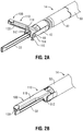
FIG. 2A is an enlarged, perspective view of a distal end portion of the ultrasonic surgical instrument ofFIG. 1A , wherein the end effector is disposed in the open condition and wherein a distal portion of the outer sleeve is removed to illustrate the components hidden thereby; -
FIG. 2B is an enlarged, perspective view of the distal end portion of the ultrasonic surgical instrument ofFIG. 1A , wherein the end effector is disposed in a clamping condition; -
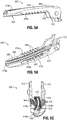
FIGS. 3A-3C are various views of a jaw member provided in accordance with the present disclosure and configured for use with the end effector of the ultrasonic surgical instrument ofFIG. 1 ; -
FIGS. 4A-4C are various views of another jaw member provided in accordance with the present disclosure and configured for use with the end effector of the ultrasonic surgical instrument ofFIG. 1 ; and -
FIGS. 5A-5C are various views of yet another jaw member provided in accordance with the present disclosure and configured for use with the end effector of the ultrasonic surgical instrument ofFIG. 1 . - Jaw members and surgical instruments including such jaw members are provided in accordance with the present disclosure and detailed hereinbelow. Referring to
FIG. 1 , although the jaw members of the present disclosure are described for use with an ultrasonicsurgical instrument 10, the jaw members of the present disclosure may alternatively be configured for use with any other suitable surgical instrument, including ultrasonic surgical instruments different from ultrasonicsurgical instrument 10. - Ultrasonic
surgical instrument 10 generally includes ahandle assembly 12, anelongated body portion 14, and anend effector 16.Handle assembly 12 supports a power supply, e.g., abattery assembly 18, and an ultrasonic transducer and generator assembly ("TAG") 20, although ultrasonicsurgical instrument 10 may alternatively be configured as a tethered instrument wherein the power supply and generator are remote components coupled to handleassembly 12 via one or more surgical cables (not shown).Handle assembly 12 includes arotation wheel 22, anactivation button 24, and aclamp trigger 26.Battery assembly 18 andTAG 20 are each releasably coupled to handleassembly 12 and are removable therefrom to facilitate disposal of any disposable components, e.g.,handle assembly 12,elongated body portion 14, and/orend effector 16, and reprocessing of any reusable components, e.g.,battery assembly 18 andTAG 20. - With additional reference to
FIGS. 2A and 2B ,elongated body portion 14 includes awaveguide 30 which extends fromhandle assembly 12 toend effector 16. Ablade 32 ofend effector 16 extends distally fromwaveguide 30. A proximal end portion ofwaveguide 30 is configured to engage the ultrasonic transducer ofTAG 20 to enable the transmission of ultrasonic energy alongwaveguide 30 from the ultrasonic transducer ofTAG 20 toblade 32. - Elongated
body portion 14 further includes aninner tube 40 disposed aboutwaveguide 30 and extending betweenhandle assembly 12 andend effector 16.Inner tube 40, more specifically, includes a proximal end portion that extends intohandle assembly 12.Inner tube 40 further includes a distal end portion including a pair of spaced-apart support arms 42 (only one of which is illustrated inFIG. 2A ), each defining atransverse aperture 44 therethrough.Apertures 44 are configured to pivotably receivepivot bosses 114 ofproximal flanges 112 ofstructural body 110 ofjaw member 100 ofend effector 16 to pivotably engagejaw member 100 toinner tube 40 at the distal end portion thereof. - An
outer tube 50 is slidably disposed aboutinner tube 40 and similarly extends betweenhandle assembly 12 andend effector 16.Outer tube 50, more specifically, includes a proximal end portion that extends intohandle assembly 12 and operably couples toclamp trigger 26 by way of a drive assembly (not shown), and a distal end portion defining a cut-out (not shown) that operably receiveslegs 116 ofproximal flanges 112 ofstructural body 110 ofjaw member 100. As a result of this configuration,clamp trigger 26 may be manipulated between an un-actuated position and an actuated position to translateouter tube 50 between an advanced position and a retracted position, thereby pivotingjaw member 100 between an open position (FIGS. 1 and2A ), whereinjaw member 100 is spaced-apart fromblade 32, and a closed position (FIG. 2B ), whereinjaw member 100 is approximated relative toblade 32. Alternatively, the arrangement of inner andouter tubes -
Rotation wheel 22 is operably coupled towaveguide 30,inner tube 40, andouter tube 50 such that rotation ofrotation wheel 22 relative to handleassembly 12 similarly rotateswaveguide 30,inner tube 40, andouter tube 50 relative to handleassembly 12, thereby also rotatingblade 32 andjaw member 100 relative to handleassembly 12 in a similar manner.Activation button 24 is configured to selectively activatebattery assembly 18 andTAG 20 to produce ultrasonic energy that is transmitted alongwaveguide 30 toblade 32 ofend effector 16. - As detailed above,
jaw member 100 includes astructural body 110 including a pair ofproximal flanges 112 which enable pivotable coupling ofjaw member 100 withinner tube 40 and operable coupling ofjaw member 100 withouter tube 50.Structural body 110 ofjaw member 100 further includes an elongateddistal portion 118 extending distally from the pair ofproximal flanges 112. Ajaw liner 130 is engaged with elongateddistal portion 118 ofstructural body 110 and is positioned to opposeblade 32 such thatblade 32 is inhibited from contactingstructural body 110 ofjaw member 100. As a result, the transfer of ultrasonic vibrations and/or thermal energy fromblade 32 tostructural body 110 during use is reduced.Jaw liner 130 may be formed from a compliant material, e.g., PTFE, or maybe otherwise formed. - With general reference to
FIGS. 1-2B , in use,ultrasonic instrument 10 is advanced into a surgical site and manipulated such thatend effector 16 is positioned with tissue to be treated disposed betweenjaw member 100 andblade 32 withjaw member 100 disposed in the open position (FIGS. 1 and2A ). Thereafter, clamptrigger 26 is squeezed towardsbattery assembly 18 from the un-actuated position to the actuated position to translateouter tube 50 aboutinner tube 40 and relative to endeffector 16, thereby pivotingjaw member 100 relative toblade 32 from the open position to the closed position to clamp tissue betweenjaw member 100 andblade 32 and, more specifically, betweenjaw liner 130 ofjaw member 100 andblade 32.Blade 32 may then be activated, e.g., via depression ofactivation button 24, to supply ultrasonic energy fromTAG 20, alongwaveguide 30, toblade 32. The ultrasonic energy provided atblade 32 is used to treat, e.g., coagulate, cauterize, fuse, seal, cut, desiccate, fulgurate, etc., tissue clamped betweenjaw member 100 andblade 32. - With reference to
FIGS. 3A-5C , variousdifferent jaw members ultrasonic instrument 10 are described. Eachjaw member jaw member 100, and may include any of the features thereof, except as specifically contradicted below. - Referring to
FIGS. 3A-3C ,jaw member 200, includes astructural body 210 and ajaw liner 230.Structural body 210 includes a pair of proximal flanges 212 (each including apivot boss 214 and a leg 216) and an elongateddistal portion 218 extending distally from the pair ofproximal flange 212.Structural body 210 is relatively rigid to provide integrity and support tojaw member 200 to enablejaw member 200 to apply sufficient clamping pressure to tissue grasped between jaw member and an opposing structure, e.g., blade 32 (FIGS. 1-2B ).Structural body 210 may be fabricated from a metal, for example, stainless steel, or any other suitable material, and may be monolithically formed via machining, stamping, metal injection molding, or may be formed in any other suitable manner via any other suitable process. - Elongated
distal portion 218 ofstructural body 210 ofjaw member 200, as noted above, extends distally from the pair ofproximal flanges 212. Elongateddistal portion 218 may define a curved configuration, as illustrated, or may define a linear configuration or a different curved configuration. Elongateddistal portion 218, more specifically, includes abase 219a and first andsecond sidewalls base 219a.Base 219a is configured to engagejaw liner 230, e.g., in complementary-fit engagement therewith. -
Sidewalls distal portion 218 ofstructural body 210 ofjaw member 200 extend beyond a tissue-contactingsurface 232 ofjaw liner 230 on either side thereof, define grippingteeth 240, and extend along a distal portion of the length of elongateddistal portion 218. More specifically,sidewalls distal portion 218, for example, no more than a distal 50% of the length thereof, no more than a distal 40% of the length thereof, or no more than a distal 30% of the length thereof, in embodiments, although other configurations are also contemplated. The other portions ofsidewalls surface 232 ofjaw liner 230, in embodiments. Grippingteeth 240 ofsidewalls - By extending beyond tissue-contacting
surface 232 ofjaw liner 230, grippingteeth 240 facilitate maintaining tissue in position betweenjaw member 200 and an opposing structure, e.g., blade 32 (FIGS. 1-2B ), during tissue treatment, thus inhibiting tissue slippage, all without interfering with the opposing structure, e.g., blade 32 (FIGS. 1-2B ). - Referring to
FIGS. 4A-4C ,jaw member 300 is similar to jaw member 200 (FIGS. 3A-3C ) and, thus, only differences therebetween are described in detail below.Jaw member 300 includes astructural body 310 and ajaw liner 330.Structural body 310 includes a pair ofproximal flanges 312 and an elongateddistal portion 318 extending distally from the pair ofproximal flange 312. - Elongated
distal portion 318 ofstructural body 310 ofjaw member 300 includes abase 319a and first andsecond sidewalls base 319a.Base 319a is configured to engagejaw liner 330.Sidewalls distal portion 318 ofstructural body 310 ofjaw member 300 extend beyond a tissue-contactingsurface 332 ofjaw liner 330 on either side thereof, define grippingteeth 340, and extend along a substantial portion of the length of elongateddistal portion 318, for example, at least 70% of the length thereof, at least 80% of the length thereof, or at least 90% of the length thereof, in embodiments, although other configurations are also contemplated. Grippingteeth 340 ofsidewalls teeth 342, wherein theteeth 342 define substantially similar heights and spacing therebetween (within manufacturing tolerances), and a distal portion ofteeth 344 that generally taper in height in the proximal-to-distal direction and/or may define decreased spacing therebetween in the proximal-to-distal direction, although other configurations are also contemplated. - Referring to
FIGS. 5A-5C ,jaw member 400 is similar tojaw members 200, 300 (FIGS. 3A-3C and4A-4C , respectively) and, thus, only differences therebetween are described in detail below.Jaw member 400 includes astructural body 410 and ajaw liner 430.Structural body 410 includes a pair ofproximal flanges 412 and an elongateddistal portion 418 extending distally from the pair ofproximal flange 412. - Elongated
distal portion 418 ofstructural body 410 ofjaw member 400 includes abase 419a and first andsecond sidewalls base 419a.Base 419a is configured to engagejaw liner 430.Sidewalls distal portion 418 ofstructural body 410 ofjaw member 400 extend beyond a tissue-contactingsurface 432 ofjaw liner 430 on either side thereof, define grippingteeth 440, and extend along a proximal portion of the length of elongateddistal portion 418, for example, no more than a proximal 750% of the length thereof, no more than a proximal 60% of the length thereof, or no more than a proximal 50% of the length thereof, in embodiments, although other configurations are also contemplated. Grippingteeth 440 ofsidewalls - While several embodiments of the disclosure have been described above and illustrated in the drawings, it is not intended that the disclosure be limited thereto, as it is intended that the disclosure be as broad in scope as the art will allow and that the specification be read likewise. Therefore, the above description should not be construed as limiting, but merely as exemplifications of particular embodiments. Those skilled in the art will envision other modifications within the scope and spirit of the claims appended hereto.
The invention may be described by reference to the following numbered paragraphs:- - 1. A jaw member for a surgical instrument, the jaw member comprising:
- a structural body including a proximal flange portion and an elongated distal portion extending distally from the proximal flange portion, the elongated distal portion including a base and first and second sidewalls extending from either side of the base along at least a portion of a length of the elongated distal portion; and
- a jaw liner engaged with the base of the elongated distal portion, the jaw liner defining a tissue-contacting surface,
- wherein the first and second sidewalls extend beyond the tissue-contacting surface of the jaw liner, the first and second sidewalls configured to facilitate gripping tissue between the structural body and an opposed structure.
- 2. The jaw member according to paragraph 1, wherein the first and second sidewalls each define a plurality of gripping teeth.
- 3. The jaw member according to paragraph 2, wherein the plurality of gripping teeth have substantially similar heights.
- 4. The jaw member according to paragraph 2, wherein at least two of the plurality of gripping teeth define different heights.
- 5. The jaw member according to paragraph 2, wherein the plurality of gripping teeth are substantially equally spaced along the sidewalls.
- 6. The jaw member according to paragraph 2, wherein at least two pairs of the plurality of gripping teeth are differently spaced along the sidewalls.
- 7. The jaw member according to paragraph 1, wherein the first and second sidewalls only extend along a distal portion of the elongated distal portion of the structural body.
- 8. The jaw member according to paragraph 1, wherein the first and second sidewalls only extend along a proximal portion of the elongated distal portion of the structural body.
- 9. The jaw member according to paragraph 1, wherein the first and second sidewalls extend along substantially the entire length of the elongated distal portion of the structural body.
- 10. A surgical instrument, comprising:
- an energy-delivering component; and
- a jaw member positioned to oppose the energy-delivering component and movable relative thereto between an open position and a closed position for clamping tissue between the jaw member and the energy-delivering component, the jaw member including:
- a structural body including a proximal flange portion and an elongated distal portion extending distally from the proximal flange portion, the elongated distal portion including a base and first and second sidewalls extending from either side of the base along at least a portion of a length of the elongated distal portion; and
- a jaw liner engaged with the base of the elongated distal portion, the jaw liner defining a tissue-contacting surface,
- wherein the first and second sidewalls extend beyond the tissue-contacting surface of the jaw liner, the first and second sidewalls configured to facilitate gripping tissue between the structural body and the energy-delivering component.
- 11. The surgical instrument according to
paragraph 10, wherein the energy-delivering component is an ultrasonic blade. - 12. The surgical instrument according to
paragraph 10, wherein the first and second sidewalls each define a plurality of gipping teeth. - 13. The surgical instrument according to
paragraph 12, wherein the plurality of gripping teeth have substantially similar heights. - 14. The surgical instrument according to
paragraph 12, wherein at least two of the plurality of gripping teeth have different heights. - 15. The surgical instrument according to
paragraph 12, wherein the plurality of gripping teeth are substantially similarly spaced along the sidewalls. - 16. The surgical instrument according to
paragraph 12, wherein at least two pairs of the plurality of gripping teeth are differently spaced along the sidewalls. - 17. The surgical instrument according to
paragraph 10, wherein the first and second sidewalls only extend along a distal portion of the elongated distal portion of the structural body. - 18. The surgical instrument according to
paragraph 10, wherein the first and second sidewalls only extend along a proximal portion of the elongated distal portion of the structural body. - 19. The surgical instrument according to
paragraph 10, wherein the first and second sidewalls extend along substantially the entire length of the elongated distal portion of the structural body.
Claims (10)
- A jaw member for a surgical instrument, the jaw member comprising:a structural body including a proximal flange portion and an elongated distal portion extending distally from the proximal flange portion, the elongated distal portion including a base and first and second sidewalls extending from either side of the base along at least a portion of a length of the elongated distal portion; anda jaw liner engaged with the base of the elongated distal portion, the jaw liner defining a tissue-contacting surface,wherein the first and second sidewalls extend beyond the tissue-contacting surface of the jaw liner, the first and second sidewalls configured to facilitate gripping tissue between the structural body and an opposed structure.
- The jaw member according to claim 1, wherein the first and second sidewalls each define a plurality of gripping teeth.
- The jaw member according to claim 2, wherein the plurality of gripping teeth have substantially similar heights.
- The jaw member according to claim 2, wherein at least two of the plurality of gripping teeth define different heights.
- The jaw member according to claim 2, 3 or 4, wherein the plurality of gripping teeth are substantially equally spaced along the sidewalls.
- The jaw member according to claim 2, 3 or 4, wherein at least two pairs of the plurality of gripping teeth are differently spaced along the sidewalls.
- The jaw member according to any preceding claim , wherein the first and second sidewalls only extend along a distal portion of the elongated distal portion of the structural body.
- The jaw member according to any one of claims 1 to 6, wherein the first and second sidewalls only extend along a proximal portion of the elongated distal portion of the structural body.
- The jaw member according to any one of claims 1 to 6, wherein the first and second sidewalls extend along substantially the entire length of the elongated distal portion of the structural body.
- A surgical instrument, comprising:an energy-delivering component; anda jaw member as claimed in any preceding claim positioned to oppose the energy-delivering component and movable relative thereto between an open position and a closed position for clamping tissue between the jaw member and the energy-delivering component, the jaw
Applications Claiming Priority (1)
| Application Number | Priority Date | Filing Date | Title |
|---|---|---|---|
| US15/876,691 US11076910B2 (en) | 2018-01-22 | 2018-01-22 | Jaw members for surgical instruments and surgical instruments incorporating the same |
Publications (1)
| Publication Number | Publication Date |
|---|---|
| EP3513758A1 true EP3513758A1 (en) | 2019-07-24 |
Family
ID=65138865
Family Applications (1)
| Application Number | Title | Priority Date | Filing Date |
|---|---|---|---|
| EP19152735.7A Pending EP3513758A1 (en) | 2018-01-22 | 2019-01-21 | Jaw members for surgical instruments and surgical instruments incorporating the same |
Country Status (2)
| Country | Link |
|---|---|
| US (1) | US11076910B2 (en) |
| EP (1) | EP3513758A1 (en) |
Families Citing this family (5)
| Publication number | Priority date | Publication date | Assignee | Title |
|---|---|---|---|---|
| US11883058B2 (en) * | 2019-03-26 | 2024-01-30 | Covidien Lp | Jaw members, end effector assemblies, and ultrasonic surgical instruments including the same |
| JP7627234B2 (en) * | 2019-05-30 | 2025-02-05 | ストライカー・ユーロピアン・オペレーションズ・リミテッド | Electrosurgical electrodes and electrosurgical tools for delivering electrical energy - Patents.com |
| JP2023523507A (en) * | 2020-02-14 | 2023-06-06 | コヴィディエン リミテッド パートナーシップ | A cartridge holder for surgical staples and having ridges on the peripheral wall for gripping tissue |
| US11648690B2 (en) * | 2020-08-21 | 2023-05-16 | House of Design LLC | Robotic end-of-arm tools and methods of use |
| US11540826B2 (en) * | 2020-11-04 | 2023-01-03 | Cilag Gmbh International | Surgical stapler end effector sled having cartridge wall support feature |
Citations (7)
| Publication number | Priority date | Publication date | Assignee | Title |
|---|---|---|---|---|
| US5304203A (en) * | 1992-10-20 | 1994-04-19 | Numed Technologies, Inc. | Tissue extracting forceps for laparoscopic surgery |
| US6129735A (en) * | 1996-06-21 | 2000-10-10 | Olympus Optical Co., Ltd. | Ultrasonic treatment appliance |
| US6887240B1 (en) * | 1995-09-19 | 2005-05-03 | Sherwood Services Ag | Vessel sealing wave jaw |
| US20070270798A1 (en) * | 2006-05-19 | 2007-11-22 | Ifung Lu | Bipolar forceps |
| EP2361048A2 (en) * | 2008-09-03 | 2011-08-31 | Ethicon Endo-Surgery, Inc. | Surgical grasping device |
| US20150297255A1 (en) * | 2014-04-16 | 2015-10-22 | Gyrus Acmi, Inc. D.B.A. Olympus Surgical Technologies America | Surgical operating apparatus with temperature control |
| EP3216410A1 (en) * | 2015-09-25 | 2017-09-13 | Olympus Corporation | Power device, surgery system including power device, and method for operating power device |
Family Cites Families (125)
| Publication number | Priority date | Publication date | Assignee | Title |
|---|---|---|---|---|
| US2397823A (en) * | 1941-02-12 | 1946-04-02 | Carl W Walter | Forceps |
| US3404683A (en) * | 1966-02-23 | 1968-10-08 | American Hospital Supply Corp | Disposable plastic hemostat |
| US3503396A (en) * | 1967-09-21 | 1970-03-31 | American Hospital Supply Corp | Atraumatic surgical clamp |
| US3469211A (en) | 1967-10-16 | 1969-09-23 | Branson Instr | Oscillatory circuit for electro-acoustic converter with starting means |
| US4277710A (en) | 1979-04-30 | 1981-07-07 | Dukane Corporation | Control circuit for piezoelectric ultrasonic generators |
| WO1984003828A1 (en) | 1983-04-04 | 1984-10-11 | Sumitomo Bakelite Co | Ultrasonic oscillator |
| US4922902A (en) | 1986-05-19 | 1990-05-08 | Valleylab, Inc. | Method for removing cellular material with endoscopic ultrasonic aspirator |
| US4827911A (en) | 1986-04-02 | 1989-05-09 | Cooper Lasersonics, Inc. | Method and apparatus for ultrasonic surgical fragmentation and removal of tissue |
| US4965532A (en) | 1988-06-17 | 1990-10-23 | Olympus Optical Co., Ltd. | Circuit for driving ultrasonic transducer |
| US5180363A (en) | 1989-04-27 | 1993-01-19 | Sumitomo Bakelite Company Company Limited | Operation device |
| US4973876A (en) | 1989-09-20 | 1990-11-27 | Branson Ultrasonics Corporation | Ultrasonic power supply |
| US5014407A (en) | 1989-09-28 | 1991-05-14 | Boughten Larry R | Tube expanding device |
| US5113116A (en) | 1989-10-05 | 1992-05-12 | Firma J. Eberspacher | Circuit arrangement for accurately and effectively driving an ultrasonic transducer |
| US6099550A (en) * | 1989-12-05 | 2000-08-08 | Yoon; Inbae | Surgical instrument having jaws and an operating channel and method for use thereof |
| US5330502A (en) | 1992-10-09 | 1994-07-19 | Ethicon, Inc. | Rotational endoscopic mechanism with jointed drive mechanism |
| DE9321021U1 (en) | 1992-11-30 | 1995-09-07 | Valleylab, Inc., Boulder, Col. | Ultrasonic surgical handpiece and energy initiator to maintain vibrations and linear dynamics |
| DE4322388C2 (en) | 1993-06-30 | 1996-07-18 | Hielscher Gmbh | Circuit arrangement for the safe start of ultrasonic disintegrators |
| AU7366994A (en) | 1993-07-21 | 1995-02-20 | Charles H. Klieman M.D. | Surgical instrument for endoscopic and general surgery |
| US5562682A (en) | 1993-10-08 | 1996-10-08 | Richard-Allan Medical Industries, Inc. | Surgical Instrument with adjustable arms |
| US5402793A (en) | 1993-11-19 | 1995-04-04 | Advanced Technology Laboratories, Inc. | Ultrasonic transesophageal probe for the imaging and diagnosis of multiple scan planes |
| DE4400210A1 (en) | 1994-01-05 | 1995-08-10 | Branson Ultraschall | Method and device for operating a generator for the HF energy supply of an ultrasonic transducer |
| US5816476A (en) | 1994-08-24 | 1998-10-06 | Verity Instruments Inc. | Dual frequency power supply and transducer |
| US5456684A (en) | 1994-09-08 | 1995-10-10 | Hutchinson Technology Incorporated | Multifunctional minimally invasive surgical instrument |
| US5704534A (en) | 1994-12-19 | 1998-01-06 | Ethicon Endo-Surgery, Inc. | Articulation assembly for surgical instruments |
| US5649957A (en) | 1995-06-22 | 1997-07-22 | Levin; John M. | Articulated dissector |
| US5674220A (en) * | 1995-09-29 | 1997-10-07 | Ethicon Endo-Surgery, Inc. | Bipolar electrosurgical clamping device |
| US5700952A (en) | 1995-11-28 | 1997-12-23 | Sawtek Inc. | Time domain delay measurement apparatus and associated method |
| US5797537A (en) | 1996-02-20 | 1998-08-25 | Richard-Allan Medical Industries, Inc. | Articulated surgical instrument with improved firing mechanism |
| US6887252B1 (en) | 1996-06-21 | 2005-05-03 | Olympus Corporation | Ultrasonic treatment appliance |
| US5819738A (en) * | 1996-07-03 | 1998-10-13 | Symbiosis Corporation | Jaw assembly having progressively larger teeth and endoscopic biopsy forceps instrument incorporating same |
| US5702408A (en) | 1996-07-17 | 1997-12-30 | Ethicon Endo-Surgery, Inc. | Articulating surgical instrument |
| US20050143769A1 (en) | 2002-08-19 | 2005-06-30 | White Jeffrey S. | Ultrasonic dissector |
| US6063098A (en) | 1996-12-23 | 2000-05-16 | Houser; Kevin | Articulable ultrasonic surgical apparatus |
| US8092473B2 (en) | 1997-02-03 | 2012-01-10 | Applied Medical Resources Corporation | Surgical clamp with improved traction |
| US5865361A (en) | 1997-09-23 | 1999-02-02 | United States Surgical Corporation | Surgical stapling apparatus |
| US6171316B1 (en) | 1997-10-10 | 2001-01-09 | Origin Medsystems, Inc. | Endoscopic surgical instrument for rotational manipulation |
| US5873873A (en) | 1997-10-10 | 1999-02-23 | Ethicon Endo-Surgery, Inc. | Ultrasonic clamp coagulator apparatus having improved clamp mechanism |
| US6068647A (en) | 1997-10-10 | 2000-05-30 | Ethicon Endo-Surgery, Inc. | Ultrasonic clamp coagulator apparatus having improved clamp arm tissue pad |
| US6163100A (en) | 1997-12-26 | 2000-12-19 | Asmo Co., Ltd. | Driving circuit of ultrasonic motor |
| US6454782B1 (en) | 1998-04-13 | 2002-09-24 | Ethicon Endo-Surgery, Inc. | Actuation mechanism for surgical instruments |
| US5897523A (en) | 1998-04-13 | 1999-04-27 | Ethicon Endo-Surgery, Inc. | Articulating ultrasonic surgical instrument |
| US6193709B1 (en) | 1998-05-13 | 2001-02-27 | Olympus Optical Co., Ltd. | Ultrasonic treatment apparatus |
| JP2000050660A (en) | 1998-08-03 | 2000-02-18 | Minolta Co Ltd | Circuit and device for driving actuator |
| FR2795301B1 (en) | 1999-06-25 | 2001-08-31 | Prec | ENDOSCOPIC SURGERY INSTRUMENT |
| US6524251B2 (en) | 1999-10-05 | 2003-02-25 | Omnisonics Medical Technologies, Inc. | Ultrasonic device for tissue ablation and sheath for use therewith |
| JP4233742B2 (en) | 1999-10-05 | 2009-03-04 | エシコン・エンド−サージェリィ・インコーポレイテッド | Connecting curved clamp arms and tissue pads used with ultrasonic surgical instruments |
| US6652547B2 (en) | 1999-10-05 | 2003-11-25 | Omnisonics Medical Technologies, Inc. | Apparatus and method of removing occlusions using ultrasonic medical device operating in a transverse mode |
| US20030109875A1 (en) * | 1999-10-22 | 2003-06-12 | Tetzlaff Philip M. | Open vessel sealing forceps with disposable electrodes |
| US6589239B2 (en) | 2000-02-01 | 2003-07-08 | Ashok C. Khandkar | Electrosurgical knife |
| US6569109B2 (en) | 2000-02-04 | 2003-05-27 | Olympus Optical Co., Ltd. | Ultrasonic operation apparatus for performing follow-up control of resonance frequency drive of ultrasonic oscillator by digital PLL system using DDS (direct digital synthesizer) |
| US20020002380A1 (en) | 2000-06-30 | 2002-01-03 | Bishop Gregory D. | Ultrasonic clamp and coagulation apparatus with tissue support surface |
| US6679899B2 (en) | 2000-10-20 | 2004-01-20 | Ethicon Endo-Surgery, Inc. | Method for detecting transverse vibrations in an ultrasonic hand piece |
| US6908472B2 (en) | 2000-10-20 | 2005-06-21 | Ethicon Endo-Surgery, Inc. | Apparatus and method for altering generator functions in an ultrasonic surgical system |
| US6626926B2 (en) | 2000-10-20 | 2003-09-30 | Ethicon Endo-Surgery, Inc. | Method for driving an ultrasonic system to improve acquisition of blade resonance frequency at startup |
| US6480796B2 (en) | 2000-10-20 | 2002-11-12 | Ethicon Endo-Surgery, Inc. | Method for improving the start up of an ultrasonic system under zero load conditions |
| US7273483B2 (en) | 2000-10-20 | 2007-09-25 | Ethicon Endo-Surgery, Inc. | Apparatus and method for alerting generator functions in an ultrasonic surgical system |
| US6678621B2 (en) | 2000-10-20 | 2004-01-13 | Ethicon Endo-Surgery, Inc. | Output displacement control using phase margin in an ultrasonic surgical hand piece |
| US6752815B2 (en) | 2001-01-31 | 2004-06-22 | Ethicon Endo-Surgery, Inc. | Method and waveguides for changing the direction of longitudinal vibrations |
| US20040097911A1 (en) | 2001-02-13 | 2004-05-20 | Olympus Optical Co., Ltd. | Ultrasonic operating apparartus and tool for changing tip thereof |
| ES2381407T3 (en) | 2001-04-20 | 2012-05-28 | Tyco Healthcare Group Lp | Bipolar or ultrasonic surgical device |
| US6588277B2 (en) | 2001-05-21 | 2003-07-08 | Ethicon Endo-Surgery | Method for detecting transverse mode vibrations in an ultrasonic hand piece/blade |
| DE60232737D1 (en) | 2001-10-11 | 2009-08-06 | Tyco Healthcare | LONG ULTRASONIC CUTTING BLADES OF LAMINATED SMALLER BLADES |
| US6770072B1 (en) * | 2001-10-22 | 2004-08-03 | Surgrx, Inc. | Electrosurgical jaw structure for controlled energy delivery |
| WO2003039429A2 (en) | 2001-11-07 | 2003-05-15 | Ethicon Endo-Surgery, Inc. | An ultrasonic clamp coagulator apparatus having an improved clamping end-effector |
| JP2003284367A (en) | 2002-03-26 | 2003-10-03 | Seiko Instruments Inc | Ultrasonic motor control system |
| JP4388475B2 (en) | 2002-08-02 | 2009-12-24 | オリンパス株式会社 | Ultrasonic treatment device |
| US20060100646A1 (en) | 2003-02-18 | 2006-05-11 | Hart Charles C | Surgical clip and method for making same |
| US8469993B2 (en) * | 2003-06-18 | 2013-06-25 | Boston Scientific Scimed, Inc. | Endoscopic instruments |
| JP4129217B2 (en) | 2003-09-29 | 2008-08-06 | オリンパス株式会社 | Ultrasonic surgery system, abnormality detection method and abnormality detection program thereof |
| US20050192610A1 (en) | 2004-02-27 | 2005-09-01 | Houser Kevin L. | Ultrasonic surgical shears and tissue pad for same |
| US7247141B2 (en) | 2004-03-08 | 2007-07-24 | Ethicon Endo-Surgery, Inc. | Intra-cavitary ultrasound medical system and method |
| EP1750608B1 (en) | 2004-06-02 | 2012-10-03 | Medtronic, Inc. | Ablation device with jaws |
| JP5009159B2 (en) | 2004-10-08 | 2012-08-22 | エシコン・エンド−サージェリィ・インコーポレイテッド | Ultrasonic surgical instrument |
| US7559450B2 (en) | 2005-02-18 | 2009-07-14 | Ethicon Endo-Surgery, Inc. | Surgical instrument incorporating a fluid transfer controlled articulation mechanism |
| WO2006125066A2 (en) | 2005-05-18 | 2006-11-23 | Richard Paschke | System and method for dynamic control of ultrasonic magnetostrictive dental scaler |
| US8579176B2 (en) | 2005-07-26 | 2013-11-12 | Ethicon Endo-Surgery, Inc. | Surgical stapling and cutting device and method for using the device |
| US7475801B2 (en) | 2005-12-29 | 2009-01-13 | Dukane Corporation | Systems for providing controlled power to ultrasonic welding probes |
| US7481824B2 (en) | 2005-12-30 | 2009-01-27 | Ethicon Endo-Surgery, Inc. | Surgical instrument with bending articulation controlled articulation pivot joint |
| US7621930B2 (en) | 2006-01-20 | 2009-11-24 | Ethicon Endo-Surgery, Inc. | Ultrasound medical instrument having a medical ultrasonic blade |
| US7514844B2 (en) | 2006-01-23 | 2009-04-07 | Avago Technologies Wireless Ip (Singapore) Pte. Ltd. | Acoustic data coupling system and method |
| US8161977B2 (en) | 2006-01-31 | 2012-04-24 | Ethicon Endo-Surgery, Inc. | Accessing data stored in a memory of a surgical instrument |
| US8366727B2 (en) | 2006-06-01 | 2013-02-05 | Ethicon Endo-Surgery, Inc. | Tissue pad ultrasonic surgical instrument |
| US7513160B2 (en) | 2006-06-05 | 2009-04-07 | Luna Innovations Incorporated | Digital pulsed phase locked loop |
| US20080188877A1 (en) | 2007-02-05 | 2008-08-07 | Hickingbotham Dyson W | Instruments For Removing an Object From the Eye |
| US8226675B2 (en) | 2007-03-22 | 2012-07-24 | Ethicon Endo-Surgery, Inc. | Surgical instruments |
| KR100739524B1 (en) | 2007-04-09 | 2007-07-13 | 주식회사 룩센테크놀러지 | Sine wave generator with automatic starting circuit |
| US8409245B2 (en) | 2007-05-22 | 2013-04-02 | Woojin Lee | Surgical instrument |
| US7588176B2 (en) | 2007-06-18 | 2009-09-15 | Ethicon Endo-Surgery, Inc. | Surgical cutting instrument with improved closure system |
| US7482888B1 (en) | 2007-07-12 | 2009-01-27 | Zerog Wireless, Inc. | Fast startup resonant element oscillator |
| US8523889B2 (en) | 2007-07-27 | 2013-09-03 | Ethicon Endo-Surgery, Inc. | Ultrasonic end effectors with increased active length |
| US8882791B2 (en) | 2007-07-27 | 2014-11-11 | Ethicon Endo-Surgery, Inc. | Ultrasonic surgical instruments |
| US9044261B2 (en) | 2007-07-31 | 2015-06-02 | Ethicon Endo-Surgery, Inc. | Temperature controlled ultrasonic surgical instruments |
| US8512365B2 (en) | 2007-07-31 | 2013-08-20 | Ethicon Endo-Surgery, Inc. | Surgical instruments |
| US8579897B2 (en) | 2007-11-21 | 2013-11-12 | Ethicon Endo-Surgery, Inc. | Bipolar forceps |
| US8556151B2 (en) | 2007-09-11 | 2013-10-15 | Covidien Lp | Articulating joint for surgical instruments |
| US8257386B2 (en) | 2007-09-11 | 2012-09-04 | Cambridge Endoscopic Devices, Inc. | Surgical instrument |
| US10010339B2 (en) | 2007-11-30 | 2018-07-03 | Ethicon Llc | Ultrasonic surgical blades |
| US20090143800A1 (en) | 2007-12-03 | 2009-06-04 | Derek Dee Deville | Cordless Hand-Held Ultrasonic Cautery Cutting Device |
| GB2456561A (en) | 2008-01-18 | 2009-07-22 | Gyrus Medical Ltd | An articulated surgical instrument having cam and track actuacting means |
| US20090198272A1 (en) | 2008-02-06 | 2009-08-06 | Lawrence Kerver | Method and apparatus for articulating the wrist of a laparoscopic grasping instrument |
| US20090264909A1 (en) | 2008-04-18 | 2009-10-22 | Jean Michael Beaupre | Ultrasonic shears stop pad |
| US9247953B2 (en) | 2008-08-01 | 2016-02-02 | Syntheon, Llc | Medical ultrasonic cauterization and cutting device and method |
| US8632539B2 (en) | 2009-01-14 | 2014-01-21 | Covidien Lp | Vessel sealer and divider |
| EP3263054B1 (en) | 2009-07-15 | 2019-03-13 | Ethicon LLC | Ultrasonic surgical instruments having clamp |
| US8461744B2 (en) * | 2009-07-15 | 2013-06-11 | Ethicon Endo-Surgery, Inc. | Rotating transducer mount for ultrasonic surgical instruments |
| US8038693B2 (en) | 2009-10-21 | 2011-10-18 | Tyco Healthcare Group Ip | Methods for ultrasonic tissue sensing and feedback |
| WO2011099571A1 (en) | 2010-02-12 | 2011-08-18 | オリンパスメディカルシステムズ株式会社 | Ultrasonic treatment device |
| JP6054298B2 (en) | 2010-11-05 | 2016-12-27 | エシコン・エンド−サージェリィ・インコーポレイテッドEthicon Endo−Surgery,Inc. | Surgical instrument with modular end effector |
| US8444664B2 (en) | 2011-05-16 | 2013-05-21 | Covidien Lp | Medical ultrasound instrument with articulated jaws |
| US9636167B2 (en) | 2011-05-31 | 2017-05-02 | Covidien Lp | Surgical device with DC power connection |
| US10004526B2 (en) | 2011-07-25 | 2018-06-26 | Covidien Lp | Ultrasonic dissection system |
| US20130085419A1 (en) | 2011-09-29 | 2013-04-04 | Tyco Healthcare Group Lp | Transducer/Waveguide Engagement Mechanisms for Ultrasonic Surgical Instruments |
| US8662745B2 (en) | 2011-11-11 | 2014-03-04 | Covidien Lp | Methods of measuring conditions of an ultrasonic instrument |
| US9351753B2 (en) | 2012-01-30 | 2016-05-31 | Covidien Lp | Ultrasonic medical instrument with a curved waveguide |
| US9011434B2 (en) * | 2012-01-31 | 2015-04-21 | Boston Scientific Scimed, Inc. | Multi-functional medical device and related methods of use |
| US8887373B2 (en) * | 2012-02-24 | 2014-11-18 | Covidien Lp | Vessel sealing instrument with reduced thermal spread and method of manufacture therefor |
| US8968311B2 (en) * | 2012-05-01 | 2015-03-03 | Covidien Lp | Surgical instrument with stamped double-flag jaws and actuation mechanism |
| US9554820B2 (en) | 2012-06-01 | 2017-01-31 | Covidien Lp | Ultrasonic surgical instrument |
| US9039691B2 (en) * | 2012-06-29 | 2015-05-26 | Covidien Lp | Surgical forceps |
| US9510906B2 (en) | 2013-03-15 | 2016-12-06 | Ethicon Endo-Surgery, Llc | Tissue clamping features of surgical instrument end effector |
| US9943357B2 (en) * | 2013-09-16 | 2018-04-17 | Covidien Lp | Split electrode for use in a bipolar electrosurgical instrument |
| US9724120B2 (en) | 2013-12-17 | 2017-08-08 | Ethicon Endo-Surgery, Llc | Clamp arm features for ultrasonic surgical instrument |
| CN106132329B (en) | 2014-03-14 | 2019-01-22 | 奥林巴斯株式会社 | Handling unit and bipolar treatment tool |
| US10368940B2 (en) * | 2015-04-10 | 2019-08-06 | Gyrus Acmi, Inc. | Medical forceps with offset teeth |
| US10603065B2 (en) | 2016-02-18 | 2020-03-31 | Covidien Lp | Surgical instruments and jaw members thereof |
-
2018
- 2018-01-22 US US15/876,691 patent/US11076910B2/en active Active
-
2019
- 2019-01-21 EP EP19152735.7A patent/EP3513758A1/en active Pending
Patent Citations (7)
| Publication number | Priority date | Publication date | Assignee | Title |
|---|---|---|---|---|
| US5304203A (en) * | 1992-10-20 | 1994-04-19 | Numed Technologies, Inc. | Tissue extracting forceps for laparoscopic surgery |
| US6887240B1 (en) * | 1995-09-19 | 2005-05-03 | Sherwood Services Ag | Vessel sealing wave jaw |
| US6129735A (en) * | 1996-06-21 | 2000-10-10 | Olympus Optical Co., Ltd. | Ultrasonic treatment appliance |
| US20070270798A1 (en) * | 2006-05-19 | 2007-11-22 | Ifung Lu | Bipolar forceps |
| EP2361048A2 (en) * | 2008-09-03 | 2011-08-31 | Ethicon Endo-Surgery, Inc. | Surgical grasping device |
| US20150297255A1 (en) * | 2014-04-16 | 2015-10-22 | Gyrus Acmi, Inc. D.B.A. Olympus Surgical Technologies America | Surgical operating apparatus with temperature control |
| EP3216410A1 (en) * | 2015-09-25 | 2017-09-13 | Olympus Corporation | Power device, surgery system including power device, and method for operating power device |
Also Published As
| Publication number | Publication date |
|---|---|
| US20190223939A1 (en) | 2019-07-25 |
| US11076910B2 (en) | 2021-08-03 |
Similar Documents
| Publication | Publication Date | Title |
|---|---|---|
| US11076910B2 (en) | Jaw members for surgical instruments and surgical instruments incorporating the same | |
| US20260026832A1 (en) | Surgical instruments with articulating shafts | |
| US11484333B2 (en) | Method of operating an articulating ultrasonic surgical instrument | |
| US11304719B2 (en) | Ultrasonic dissector and sealer | |
| US9113909B2 (en) | Surgical vessel sealer and divider | |
| US11571237B2 (en) | Surgical instruments and jaw members thereof | |
| US20170056059A1 (en) | Ultrasonic surgical instrument with replacable clamp pad | |
| US20130066303A1 (en) | Rotation Knobs for Surgical Instruments | |
| JP2010522032A (en) | Surgical instruments | |
| BR112017022198B1 (en) | Device for operating on fabric | |
| BR112014032929B1 (en) | JOINT SURGICAL INSTRUMENT | |
| US20250331882A1 (en) | Jaw drive arm for surgical instruments and surgical instruments incorporating the same | |
| CN105943125A (en) | Ultrasonic scalpel head with clamping arm driving component | |
| US11883058B2 (en) | Jaw members, end effector assemblies, and ultrasonic surgical instruments including the same | |
| EP3824826A1 (en) | Surgical ultrasonic instruments incorporating cooling features | |
| US10987124B2 (en) | Surgical instruments and jaw members thereof | |
| BR112018012535B1 (en) | ULTRASONIC SURGICAL INSTRUMENT WITH TUBULAR SEGMENT OF ACOUSTIC WAVE GUIDE | |
| US20190038308A1 (en) | Jaw members for surgical instruments and surgical instruments incorporating the same | |
| US11478268B2 (en) | Jaw members for surgical instruments and surgical instruments incorporating the same | |
| JP2000126198A (en) | Ultrasonic treatment tool | |
| EP3138523B1 (en) | Energizable surgical attachment for a mechanical clamp | |
| JP2004049554A (en) | Ultrasonic treatment instrument |
Legal Events
| Date | Code | Title | Description |
|---|---|---|---|
| PUAI | Public reference made under article 153(3) epc to a published international application that has entered the european phase |
Free format text: ORIGINAL CODE: 0009012 |
|
| STAA | Information on the status of an ep patent application or granted ep patent |
Free format text: STATUS: REQUEST FOR EXAMINATION WAS MADE |
|
| 17P | Request for examination filed |
Effective date: 20190121 |
|
| AK | Designated contracting states |
Kind code of ref document: A1 Designated state(s): AL AT BE BG CH CY CZ DE DK EE ES FI FR GB GR HR HU IE IS IT LI LT LU LV MC MK MT NL NO PL PT RO RS SE SI SK SM TR |
|
| AX | Request for extension of the european patent |
Extension state: BA ME |
|
| RBV | Designated contracting states (corrected) |
Designated state(s): AL AT BE BG CH CY CZ DE DK EE ES FI FR GB GR HR HU IE IS IT LI LT LU LV MC MK MT NL NO PL PT RO RS SE SI SK SM TR |
|
| STAA | Information on the status of an ep patent application or granted ep patent |
Free format text: STATUS: EXAMINATION IS IN PROGRESS |
|
| 17Q | First examination report despatched |
Effective date: 20230913 |