EP3513063B1 - Method of attaching a tip extension to a wind turbine blade and wind turbine blade - Google Patents
Method of attaching a tip extension to a wind turbine blade and wind turbine blade Download PDFInfo
- Publication number
- EP3513063B1 EP3513063B1 EP17768976.7A EP17768976A EP3513063B1 EP 3513063 B1 EP3513063 B1 EP 3513063B1 EP 17768976 A EP17768976 A EP 17768976A EP 3513063 B1 EP3513063 B1 EP 3513063B1
- Authority
- EP
- European Patent Office
- Prior art keywords
- blade
- tip extension
- adhesive
- tip
- dam
- Prior art date
- Legal status (The legal status is an assumption and is not a legal conclusion. Google has not performed a legal analysis and makes no representation as to the accuracy of the status listed.)
- Active
Links
Images



Classifications
-
- F—MECHANICAL ENGINEERING; LIGHTING; HEATING; WEAPONS; BLASTING
- F03—MACHINES OR ENGINES FOR LIQUIDS; WIND, SPRING, OR WEIGHT MOTORS; PRODUCING MECHANICAL POWER OR A REACTIVE PROPULSIVE THRUST, NOT OTHERWISE PROVIDED FOR
- F03D—WIND MOTORS
- F03D1/00—Wind motors with rotation axis substantially parallel to the air flow entering the rotor
- F03D1/06—Rotors
- F03D1/065—Rotors characterised by their construction elements
- F03D1/0675—Rotors characterised by their construction elements of the blades
-
- B—PERFORMING OPERATIONS; TRANSPORTING
- B60—VEHICLES IN GENERAL
- B60J—WINDOWS, WINDSCREENS, NON-FIXED ROOFS, DOORS, OR SIMILAR DEVICES FOR VEHICLES; REMOVABLE EXTERNAL PROTECTIVE COVERINGS SPECIALLY ADAPTED FOR VEHICLES
- B60J10/00—Sealing arrangements
- B60J10/15—Sealing arrangements characterised by the material
- B60J10/17—Sealing arrangements characterised by the material provided with a low-friction material on the surface
-
- F—MECHANICAL ENGINEERING; LIGHTING; HEATING; WEAPONS; BLASTING
- F03—MACHINES OR ENGINES FOR LIQUIDS; WIND, SPRING, OR WEIGHT MOTORS; PRODUCING MECHANICAL POWER OR A REACTIVE PROPULSIVE THRUST, NOT OTHERWISE PROVIDED FOR
- F03D—WIND MOTORS
- F03D1/00—Wind motors with rotation axis substantially parallel to the air flow entering the rotor
- F03D1/06—Rotors
- F03D1/0608—Rotors characterised by their aerodynamic shape
- F03D1/0633—Rotors characterised by their aerodynamic shape of the blades
-
- F—MECHANICAL ENGINEERING; LIGHTING; HEATING; WEAPONS; BLASTING
- F05—INDEXING SCHEMES RELATING TO ENGINES OR PUMPS IN VARIOUS SUBCLASSES OF CLASSES F01-F04
- F05B—INDEXING SCHEME RELATING TO WIND, SPRING, WEIGHT, INERTIA OR LIKE MOTORS, TO MACHINES OR ENGINES FOR LIQUIDS COVERED BY SUBCLASSES F03B, F03D AND F03G
- F05B2240/00—Components
- F05B2240/20—Rotors
- F05B2240/30—Characteristics of rotor blades, i.e. of any element transforming dynamic fluid energy to or from rotational energy and being attached to a rotor
- F05B2240/307—Blade tip, e.g. winglets
Definitions
- the present invention relates generally to tip extensions for wind turbine blades, and more specifically to a method of attaching a tip extension to a wind turbine blade.
- a blade tip extension which may be provided in the form of a sock that fits over the tip of a blade and increases the length of the blade.
- the provision of tip extensions increases the overall length of the blades and thus increases the swept area of the rotor, allowing the wind turbine to capture more energy from the wind.
- tip extensions must be fitted accurately to the blade and attached firmly.
- the process is carried out by operators working at a significant height with exposure to often harsh climate conditions. It is therefore important to develop attachment processes that are both straightforward and reliable.
- the tip extensions should be designed to facilitate the attachment process.
- EP2365212A1 discloses a tip extension that is held onto a main blade by means of a vacuum. An air tight seal is provided between the tip extension and the blade surface to maintain the vacuum pressure.
- a method of attaching a tip extension to a tip end of a wind turbine blade comprises: providing a wind turbine blade having a tip end to be extended; providing a tip extension in the form of a sock; attaching one or more adhesive dams to an outer surface of the blade at the tip end and/or to an inner surface of the tip extension, the adhesive dam(s) being arranged to define one or more bond cavities between the outer surface of the blade and the inner surface of the tip extension when the tip extension is fitted to the blade; sliding the tip extension over the tip end of the blade; and bonding the tip extension to the blade by means of adhesive provided in the one or more bond cavities; wherein the one or more adhesive dams include a friction-reducing layer arranged to facilitate sliding of the tip extension over the tip end of the blade.
- the adhesive dam(s) may be applied to the outer surface of the blade prior to fitting the tip extension. Alternatively, the adhesive dams could be applied to an internal surface of the tip extension, or a combination of these options may be used.
- the adhesive dams serve to constrain adhesive within the bond cavities, and may also be referred to as adhesive-constraining dams.
- the adhesive dams are preferably made primarily from foam, for example PVC foam, although other suitable materials may be used.
- foam for example PVC foam, although other suitable materials may be used.
- the adhesive dams may be compressed slightly between the inner surface of the tip extension and the outer surface of the blade.
- the friction-reducing layer of the adhesive dams advantageously avoids a build up of friction occurring when the tip extension is pushed or pulled over the tip end of the blade. This allows the tip extension to slide relatively easily onto the blade and avoids the adhesive dams from being torn or dislodged or damaged during fitting.
- the method may comprise bonding the adhesive dam(s) to the outer surface of the blade.
- a gel coat and/or paint may be removed from the outer surface of the blade at the tip end prior to applying the adhesive dam(s).
- the adhesive dam may comprise a strip having a friction-reducing layer.
- the strip is preferably made from foam, for example PVC foam, although other suitable materials may be used.
- the friction-reducing layer is preferably a layer of polytetrafluoroethylene (PTFE), although other suitable non-stick or low-friction materials may be used.
- PTFE polytetrafluoroethylene
- the friction-reducing layer is preferably integral with the strip.
- the friction reducing layer is applied during manufacture of the strip.
- the friction-reducing layer may be provided on a first side of the strip.
- An adhesive layer may be provided on a second side of the strip, opposite the first side.
- the foam tape for use in the above method, wherein the foam tape comprises an integral PTFE layer on one side.
- the tape comprises an integral adhesive layer on the other side.
- the foam is PVC foam.
- the tape comprises the PTFE layer on an upper side of the foam and an adhesive layer on a lower side of the foam.
- the adhesive dam may comprise a foam strip, preferably PVC foam, having an integral friction-reducing layer such as a PTFE layer on one side and an integral adhesive layer on the other side.
- a wind turbine blade having a tip end, wherein one or more adhesive dams are provided on an outer surface of the blade at the tip end, the adhesive dam(s) comprising a strip having a friction-reducing layer.
- a tip extension is bonded to the tip end of the blade, and the one or more adhesive dams are sandwiched between the wind turbine blade and the tip extension.
- the adhesive dam(s) preferably at least partially define one or more bond cavities between the blade and the tip extension and wherein the bond cavities are at least partially filled with adhesive.
- FIG 1 is a schematic view of a horizontal axis wind turbine 10 according to an embodiment of the present invention.
- the wind turbine 10 comprises a tower 12 supporting a nacelle 14.
- a rotor 16 is mounted to the nacelle 14.
- the rotor 16 comprises a plurality of wind turbine blades 18.
- the rotor 16 comprises three blades 18, but in other embodiments the rotor 16 may have any number of blades 18.
- Each blade 18 is retro-fitted with a blade tip extension (BTE) 20, which extends the effective length of the blade 18.
- BTE blade tip extension
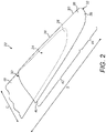
- FIG. 2 is a schematic view of a wind turbine blade assembly 22 comprising a wind turbine blade 18 fitted with a blade tip extension 20 according to an embodiment of the present invention.
- the blade tip extension 20 in this example is in the form of a sock, which fits over a tip end 24 of the blade 18.
- the tip end 24 of the blade 18 comprises a tip 26.
- the tip 26 may optionally be removed from the blade 18 prior to fitting the tip extension 20.
- the tip extension 20 comprises an outer shell 28 defining a substantially hollow interior for receiving the tip end 24 of the blade 18.
- the tip extension 20 has an inboard end 30 and an outboard end 32. When fitted to the blade 18, the inboard end 30 of the tip extension 20 is located closer to a root 33 (see Figure 1 ) of the blade 18 than the outboard end 32.
- the inboard end 30 of the tip extension 20 is open to receive the tip end 24 of the blade 18 to be extended.
- the outboard end 32 of the tip extension 20 is closed and comprises a tip 36, which forms the tip of the wind turbine blade assembly 22 when the tip extension 20 is fitted to the blade 18.
- the outer shell 28 of the tip extension 20 extends longitudinally in a lengthwise ('spanwise') direction S between the open root end 30 towards the tip 36, and extends transversely in a widthwise ('chordwise') direction C between a leading edge 38 and a trailing edge 40.
- the outer shell 28 defines an airfoil profile in cross-section.
- an inboard portion 42 (also referred to as an 'overlap portion') of the tip extension 20 overlaps the tip end 24 of the blade 18, and is bonded to the blade 18 as will be discussed in more detail later.
- An outboard portion 44 of the tip extension 20, comprising the tip-extension tip 36, serves to extend the overall length of the blade 18.
- the blade tip extension 20 has an overall length of approximately three metres.
- the inboard portion 42 has a length of approximately two metres, whilst the outboard portion 44 has a length of approximately one metre.
- the tip extension 20 extends the length of the blade 18 by approximately one metre, and provides a two-metre overlap.
- This size of tip extension is suitable for blades having an original length of approximately 40 metres.
- the tip extension may have other dimensions, and/or may be sized to fit blades having a different length. These dimensions are therefore exemplary only and are not intended to limit the scope of the invention.
- tip extension 20 in terms of its construction and method of attachment to the blade 18 will now be discussed with reference to the remaining figures.
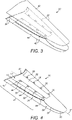
- the outer shell 28 of the tip extension 20 is formed from first and second half shells 46, 48, which are bonded together along their leading and trailing edges 38, 40 to form the blade tip extension 20.
- Each half shell 46, 48 in this example is of composite construction.
- the half shells 46, 48 are preferably each formed in a respective mould.
- the moulding process may involve resin infusion or prepreg techniques, which are known to the skilled person who is familiar with the construction of wind turbine blade shells.
- a typical resin infusion process may involve arranging a number of layers of reinforcing material such as glass- or carbon-fibre fabric in the mould to form a layup.
- the layup may be covered with a layer of vacuum film to form a sealed region encapsulating the layup.
- a vacuum pump may be used to remove air from the sealed region, and resin may be admitted into the sealed region.
- the resin infuses between the fabric layers.
- the resin subsequently cures to form the finished composite shells.
- this shows the first half shell 46 of the tip extension.
- Bond regions 50, 52 are defined on an inner surface 54 of the half shell 46 in the inboard portion 42 of the tip extension 20. As will be described in further detail later, when the tip extension 20 is fitted to the blade 18, these regions 50, 52 of the tip extension 20 are bonded to corresponding bond regions defined on the outer surface of the blade 18.
- the bond regions 50, 52 extend longitudinally in the inboard portion 42 of the half shell 46.
- the bond regions 50, 52 are spaced apart from one another in the chordwise direction of the half shell 46.
- the bond regions 50, 52 are arranged such that when the tip extension 20 is fitted to the blade 18, a first bond region 50 overlaps a trailing edge region of the blade 18, whilst a second bond region 52 overlaps a spar cap region of the blade 18.
- the first and second bond regions 50, 52 are therefore referred to hereafter as the 'trailing edge bond region' 50 and the 'spar cap bond region' 52 respectively.
- a layer of peel ply 55 is provided in the bond regions 50, 52 in this example.
- the peel ply layer 55 may be provided as the uppermost layer in the layup when forming the half shell 46 such that it is exposed on the inner surface 54 of the half shell 46.
- the peel ply layer 55 includes a protective sheet, which is removed after the moulding process to expose a rough surface in the bond regions 50, 52.
- the rough surface advantageously functions as a keying surface for the adhesive when the tip extension 20 is bonded to the blade 18. The keying surface enhances the bond strength between the tip extension 20 and the blade 18.
- Spacers 56 are provided on the inner surface 54 of the first half shell 46, outside the bond areas 50, 52. The spacers 56 ensure that there is adequate space for adhesive between the bond regions 50, 52 and the outer surface of the blade 18 when the tip extension 20 is fitted to the blade 18.
- An adhesive dam 57 is provided on the inner surface 54 of the first half shell 46 in a trailing edge region 58 of the half shell 46 near the trailing edge 40.
- the adhesive dam 57 in this example comprises a strip or tape, which is preferably made from a compressible material such as foam. Foam has particularly advantages in this context, which will be discussed in detail later.
- the adhesive dam is made from PVC (polyvinyl chloride) foam.
- the PVC foam strip 57 has approximate dimensions of 5x10 millimetres in terms of height and width. The strip is added to the first half shell 46 after the half shell 46 is finished but before the two half shells 46, 48 are bonded together.
- the PVC foam strip 57 includes an adhesive film on one side to facilitate attachment to the inner surface 54 of the first half shell 46.
- the adhesive dam 57 serves to contain adhesive that is used to bond together the trailing edges 40 of the first and second half shells 46, 48 during manufacture of the tip extension 20, as discussed further below with reference to Figures 5 and 6 .
- the adhesive dam 57 extends longitudinally in the spanwise direction S (see Figure 2 ).
- the adhesive dam is spaced from the trailing edge 40 of the first half shell 46 in the chordwise direction.
- the adhesive dam 57 extends in the spanwise direction generally parallel to the trailing edge 40 of the first half shell 46, and hence it extends non-parallel to a spanwise axis S' of the first half shell 46.
- the adhesive dam 57 extends longitudinally from the near the tip 36 to near the root 30 of the half shell 46.
- Other configurations of the adhesive dam 57 may be used in other embodiments.
- the inner surface of the second half shell 48 of the tip extension 20 is configured similarly to the first half shell 46 in that it also includes corresponding bond regions, peel ply in the bond regions and spacers outside of the bond regions.
- the adhesive dam 57 is associated only with the first half shell 46.
- the adhesive dam 57 may instead be applied to the second half shell 48, or adhesive dams may be applied to both the first and second half shells 46, 48 and optionally those adhesive dams may be arranged in contact when the half shells 46, 48 are bonded together.
- this illustrates the process of bonding the first and second half shells 46, 48 together to form the tip extension 20.
- adhesive 60 is first applied at a plurality of discrete locations spaced along the leading edge 38 of the first half shell 46.
- the second half shell 48 is positioned into a jig and then lowered into position on top of the first half shell 46 such that the leading and trailing edges 38, 40 of the respective half shells 46, 48 are mutually aligned.
- the half shells 46, 48 may then be clamped in place.
- the adhesive 60 at the leading edge 38 forms a series of spot bonds between the two shells 46, 48 at their aligned leading edges 38.
- the over-lamination process preferably involves applying layers of prepreg glass-fibre fabric across the interface of the half shells 46, 48 at the leading edge 38 using hand layup.
- the adhesive dam 57 arranged at the trailing edge 40 of the first half shell 46 is preferably compressed slightly by the inner surface 62 (indicated in Figure 9 ) of the second half shell 48.
- a trailing edge bond cavity 64 is defined between the two half shells 46, 48, which is bound by the adhesive dam 57 and the respective trailing edges 40 of the two half shells 46, 48.
- adhesive 65 is injected into the trailing edge bond cavity 64.
- the adhesive 65 is injected through at least one hole 66 provided in at least one of the half shells 46, 48.
- the hole(s) 66 communicate with the trailing edge bond cavity 64.
- a hole 66 is provided near the tip 36 of the second half shell 48.
- the injected adhesive 65 flows longitudinally from the tip 36 towards the open root end 30 of the tip extension 20.
- the adhesive dam 57 advantageously allows the position of the trailing edge bond line between the two half shells 46, 48 to be precisely defined. Without the adhesive dam 57, it would not be possible to control the chordwise position of the bond line. In particular, it would not be possible to control the position of the face 67 of the adhesive 65 that faces toward the leading edge 38 of the tip extension 20 (best shown in Figure 6 ). If the adhesive 65 was to spread too far in the chordwise direction (i.e. too far towards the leading edge 38 of the tip extension 20) then it may prevent the tip extension 20 from fitting correctly to the blade 18. This is illustrated by way of example in Figure 6 , and discussed below.
- Figure 6 shows schematic cross sections through trailing-edge portions of a blade 18 and a tip extension 20 in the case where the tip extension 20 is not provided with an adhesive dam.
- the absence of an adhesive dam means that the adhesive 65 has migrated too far in the chordwise direction away from the trailing edge 40 since it is not constrained by an adhesive dam.
- the cured adhesive 65 clashes with the trailing edge 68 of the blade 18 and prevents the tip extension 20 from fitting over the blade 18.
- the provision of a trailing-edge dam 57 in the tip extension 20 therefore prevents such clashes from occurring. It will be appreciated that the risk of a clash is only associated with the overlap region 42 of the tip extension 20 and is not a problem that exists with the outboard region 44.
- the trailing edge bond between the two half shells 46, 48 of the tip extension 20 could instead be formed by applying adhesive directly to one of the half shells 46, 48 prior to positioning the half shells 46, 48 together.
- This technique is conventionally used when joining two half shells of a wind turbine blade together.
- injection of adhesive has been found to be preferable particularly in the case of a curved tip extensions (such as the curved tip extension 20b shown in Figure 17 and discussed later) since the curved geometry of the shells does not always produce a satisfactory bond line using the conventional bonding process.
- FIG. 7 this shows the tip end 24 of a conventional wind turbine blade 18, which has been prepared for mounting of a tip extension.
- adhesive dams 70 are provided on the outer surface 72 of the blade 18 on both the pressure and suction sides of the blade 18, although only the suction side 73 of the blade 18 is visible in Figure 7 .
- the adhesive dams 70 are bonded to the outer surface 72 of the blade 18 and are arranged to extend along pre-defined boundaries of bond regions 74, 76 defined on the outer surface 70 of the blade 18.
- a trailing edge bond region 74 is defined near the trailing edge 68 of the blade 18 and a spar cap bond region 76 coincides with a position of a spar cap of the blade 18.
- bond regions 74, 76 are selected to coincide with the bond regions 50, 52 defined on the inner surface 54 of the tip extension 20, which were described previously with reference to Figure 4 .
- the adhesive dams 70 applied to the outer surface 72 of the blade 18 ensure that adhesive subsequently applied to bond the tip extension 20 to the blade 18 is contained within these bond regions 74, 76.
- the adhesive dams 70 may alternatively be provided inside the tip extension 20 during manufacture of the tip extension 20. However, it is advantageous to apply these dams 70 to the blade 18 because the tip extension 20 may be in storage for some time before it is used, which may cause the dams 70 to deteriorate. By installing these dams 70 on the blade 18 at the time of installation of the tip extension 20, it can be ensured that the dams 70 are of high quality without deterioration.
- the blade 18 is ready to receive the tip extension 20.
- the bond regions 74, 76 defined on the outer surface 72 of the blade 18 may be further prepared.
- the gel coat and/or paint on the outer surface 72 of the blade 18 may be removed and the bond regions 74, 76 may be cleaned and/or sanded to enhance keying to the adhesive.
- the tip extension 20 is inserted over the prepared tip end 24 of the blade 18.
- the process initially involves aligning the tip 26 of the blade 18 with the open end 30 of the tip extension 20. Once aligned, the tip extension 20 is pulled or pushed over the tip end 24 of the blade 18 in the direction of the arrows 78, i.e. towards the root of the blade 18.
- the adhesive dams 70 may be formed from or comprise materials that minimise friction between the dams 70 and the tip extension 20.
- the adhesive dams 70 comprise a strip or tape 80 having a friction-reducing layer 82 on one side.
- the tape 80 may be made from foam, e.g. PVC foam.
- the friction-reducing layer 82 in this example is a layer of polytetrafluoroethylene (PTFE) e.g. Teflon TM .
- PTFE friction-reducing layer 82 advantageously allows the tip extension 20 to slide over the blade 18 without a build up of friction.
- An adhesive layer 86 is preferably provided on the other side of the tape 80 to facilitate attachment of the adhesive dam 70 to the surface of the blade 18.
- the PTFE layer 82 is preferably and advantageously provided as an integral layer of the adhesive dam 70.
- the PTFE layer 82 may be provided during manufacture of the dams 70.
- the dams 70 are preferably manufactured in sheet form, wherein a layer of PTFE is bonded to an upper surface of a sheet of PVC foam, and a layer of adhesive may be bonded to the lower surface of the sheet. The sheet may then be slit to the required width of the tape to form the dams 70.
- the PTFE layer 82 may be applied subsequently to the dams 70, for example after the dams 70 have been manufactured or after the dams 70 have been applied to the blade 18, there is a risk of such subsequently-applied PTFE layers 82 becoming displaced or detached from the dams 70 during fitting of the tip extension 20 to the blade 18. If the PTFE layer 82 or part of it is displaced into the bond regions 74, 76 (shown in Figure 7 ) then it may act as a crack initiator. It is therefore preferable and advantageous to integrate the PTFE layer 82 into the structure of the dams 70 to avoid such problems. It also facilitates attachment of the tip extension 20 as there is no need to apply a PTFE layer 82 or other friction-reducing substances to the dams 70 during the attachment process.
- the tip extension 20 When the tip extension 20 is pulled or pushed over the blade 18, the adhesive dams 70 applied to the blade 18 become sandwiched between the tip extension 20 and the blade 18. It can be seen in Figure 8 that the tip extension 20 includes a plurality of pre-drilled holes 90, 91. As will be discussed in further detail later with reference to Figure 10 , the holes 90, 91 are used for supplying adhesive between the blade 18 and the tip extension 20 in order to bond the tip extension 20 to the blade 18.
- each row extends in a longitudinal (spanwise) direction and comprises a plurality of mutually-spaced holes 90, 91.
- the holes 90, 91 are arranged to communicate with bond cavities 94, 96 (indicated in Figure 9 ) defined between the outer surface 72 of the blade 18 and the inner surfaces 54, 62 of the tip extension 20, as will be discussed in further detail below with reference to Figure 9 , which is a schematic cross-section taken along the line 9-9 in Figure 8 , i.e. through the tip end 24 of the blade 18 when overlapped by the inboard portion 42 of the tip extension 20.
- an overlap region 92 is defined between the outer surface 72 of the tip end 24 of the blade 18 and the inner surfaces 54, 62 of the inboard portion 42 of the tip extension 20.
- a plurality of bond cavities 94, 96 are defined in the overlap region 92.
- the bond cavities 94, 96 are at least partially defined by the adhesive dams 70 applied to the blade 18, and which are sandwiched between the blade 18 and the inner surfaces 54, 62 of the tip extension 20.
- spar cap bond cavities 94 are defined between the opposed spar cap bond regions 76 of the blade shell 18 and the inner surfaces 54, 62 of the tip extension 20, and trailing edge bond cavities 96 are defined between the opposed trailing edge bond regions 74 of the blade shell 18 and the inner surfaces 54, 62 of the tip extension 20.
- the bond cavities 94, 96 are defined on both the windward and leeward sides 97, 73 of the blade 18.
- the spar cap bond cavities 94 are each bound in the chordwise direction C by the adhesive dams 70 applied to the surface 72 of the blade 18.
- the trailing edge bond cavities 96 are bound in the chordwise direction C by the trailing edge adhesive dam 57 provided in the tip extension 20 and by the trailing edge adhesive dams 70 applied to the surface 72 of the blade 18.
- Figure 9 also shows the spacers 56, which were discussed previously with reference to Figure 4 .
- the spacers 56 ensure that there is a minimum separation distance between the outer surface 72 of the blade 18 and the inner surfaces 54, 62 of the tip extension 20, so that there is sufficient space in the bond cavities 94, 96 for adhesive.
- the spacers 56 are substantially incompressible.
- FIG 10 this illustrates the process of bonding the tip extension 20 to the blade 18.
- the process involves injecting adhesive 98 through the holes 90, 91 provided in the tip extension 20 (see also Figure 10a , which shows adhesive 98 being injected through a hole 90a).
- the adhesive 98 is first injected through the hole 90, 91 closest to the tip 36 of the tip extension 20.
- the adhesive 98 begins to fill the associated bond cavity 94, 96 and spreads out to fill the part of the bond cavity generally beneath the hole 90, 91, whilst being constrained by the adhesive dams 57, 70 discussed previously.
- the injection process continues by injecting adhesive through the adjacent hole 90, 91 in the series.
- adhesive 98 is injected through each hole 90, 91 in the series sequentially, starting at the hole 90, 91 closest to the tip 36 and moving from hole-to-hole towards the root end 30 of the tip extension 20.
- the shell 28 of the tip extension 20 in this example is advantageously translucent, since it is composed of glass-fibre composite. This allows the flow front 100 of the adhesive 98 to be visually inspected during the injection process.
- the injection process through the current hole 90a is terminated and adhesive is injected through that next hole 90b.
- the injection through a hole 90a is terminated when the flow of adhesive is within a predetermined distance 'x' from the next hole 90b (in this example, the predetermined distance x is approximately 25 mm), and injection through that next hole 90b then commences.
- the process of injecting adhesive sequentially through the series of holes 90, 91 moving from tip 36 to root 30 advantageously prevents air lock offs and avoids voids forming in the bonds.
- stopping adhesive injection within the pre-determined distance also reduces the back pressure of adhesive, and therefore reduces the risk of breaching the adhesive dams.
- the root end 30 of the tip extension 20 is open, hence air can escape through this open end 30 as the adhesive flow front 100 moves generally in a longitudinal direction towards the open root end 30. Air can also escape through the next hole in the series of holes 90, 91.
- the adhesive dams 57, 70 in this example are advantageously permeable to air, i.e. they are not air tight, hence air can escape through the adhesive dams 57, 70.
- the bonding process described herein therefore provides an excellent and durable bond between the tip extension 20 and the blade 18 in precisely defined positions and without voids.
- FIG. 11 this schematically illustrates one potential arrangement of the adhesive dam 57 provided in the trailing edge region 58 of the tip extension.
- the adhesive dam 57 is located such that when the tip extension 20 is fitted to the blade 18, there is a gap 102 in the chordwise direction between the adhesive dam 57 and the trailing edge 68 of the blade 18. Whilst this position of the adhesive dam 57 avoids a clash condition, it presents certain problems.
- adhesive 98 when adhesive 98 is injected into the trailing edge bond cavities 96, the adhesive 98 must flow around the trailing edge 68 of the blade 18 from the leeward side 73 to the windward side 97 (or vice versa). This inevitably causes air lock-offs, resulting in voids in the adhesive 98 in the trailing edge bond cavities 96 and leading to a sub-optimal bond at the trailing edge 68.
- FIG. 12 this schematically illustrates a possible configuration that avoids the adhesive 98 needing to travel around the trailing edge 68 of the blade 18.
- additional dams 104 are provided on the pressure and suction surfaces 97, 73 of the blade 18 near the trailing edge 68.
- the additional dams 104 prevent the adhesive 98 from flowing around the trailing edge 68 of the blade 18, and hence avoid air lock-offs in the trailing edge bond cavities 96 when the tip extension 20 is bonded to the blade 18. Whilst these additional dams 104 prevent voids occurring in the adhesive 98 in the trailing edge bond cavities 96, they result in a relatively narrow bond line (in the chordwise direction) between the blade 18 and the tip extension 20 at the trailing edge 68 of the blade 18.
- a void 106 is also formed between the trailing edge 68 of the blade 18 and the adhesive dam 57 in the tip extension 20.
- a void 106 in this position is undesirable because moisture may build up in this void 106, necessitating the need for drain holes in the tip extension 20.
- air or moisture in this void 106 may expand and could burst open the void 106, i.e. burst through the shell 28 of the tip extension 20. Therefore, whilst the provision of additional adhesive dams 104 overcomes certain problems, it also presents additional ones.
- FIG 13 this schematically illustrates a preferred and particularly advantageous configuration of the adhesive dam 57 provided in the trailing edge region 58 of the tip extension 20.
- the adhesive dam 57 is advantageously made from foam.
- the adhesive dam 57 comprises a leading surface 108, which faces the leading edge 38 (indicated in Figure 5 ) of the tip extension 20 and a trailing surface 110 which faces the trailing edge 40 of the tip extension 20.
- the dam 57 is spaced apart from the trailing edge 40 such that a trailing edge cavity 64 is defined behind the dam 57, i.e. between the dam 57 and the trailing edge 40 of the tip extension 20. More specifically, the cavity 64 is defined between the trailing surface 110 of the dam 57 and the trailing edge 40 of the tip extension 20.
- the cavity 64 is filled with adhesive 65 during construction of the tip extension 20 to bond the two half shells 46, 48 of the outer shell 28 of the tip extension 20 together, as previously described.
- chordwise location of the foam dam 57 in the tip extension is selected such that the trailing edge 68 of the blade 18 projects into the foam when the tip extension 20 is fitted to the blade 18. More specifically, the chordwise location of leading surface 108 of the dam 57 is selected such that the trailing edge 68 of the blade 18 projects into the foam 57 when the tip extension 20 is fitted to the blade 18.
- the chordwise location of the leading surface 108 may selected by suitable selection of the chordwise position of the dam 57 and the chordwise width of the dam 57.
- the trailing edge 68 of the blade 18 projects into the dam 57, parts of the dam 57 overlap the pressure and suction surfaces 97, 73 of the blade 18 at the trailing edge 68.
- the trailing edge 68 is sandwiched between parts of the adhesive dam 57.
- the trailing edge 68 preferably forms an interference fit with the adhesive dam 57.
- the adhesive dam 57 may advantageously form an effective seal around the trailing edge 68.
- the adhesive dam 57 advantageously separates the leeward and windward sides 97, 73 of the blade 18 and blocks any passageway for adhesive around the trailing edge 68 of the blade 18 thus avoiding the problems discussed above with reference to Figure 11 .
- the configuration of the adhesive dam 57 shown in Figure 13 also enables a relatively wide bond 109 (in the chordwise direction) to be achieved between the blade 18 and the tip extension 20 at the trailing edge 68 of the blade 18, without the need for a void, thereby avoiding the problems discussed above with reference to the arrangement shown in Figure 12 .
- the nominal chordwise position of the foam dam 57 in the tip extension 20 may be selected so that the trailing edge 68 of the blade 18 cuts into the foam 57 by approximately five millimetres, as indicated by the arrows 112 on Figure 13 . Due to manufacturing tolerances in the blade 18, the blade 18 may have a slightly wider or narrower chord than the designed dimension. For example, the chord dimension may have a tolerance of +/- five millimetres.
- the chordwise width W of the foam dam 57 may be suitably selected to accommodate such manufacturing tolerances in the blade dimensions, as discussed below.
- the foam dam 57 may have a chordwise width W of approximately 10 mm, or slightly greater. Therefore, if the blade 18 has a wider chord than nominal (of up to about 5 mm) the trailing edge 68 will cut further into the foam dam 57 (as shown in Figure 14 ) yet the dam 57 will still separate the leeward and windward sides 73, 97 of the blade 18. Alternatively, if the blade 18 has a narrower chord than nominal (of up to about 5 mm) the trailing edge 68 will cut less far into the foam 57, yet the dam 57 will still separate the leeward and windward sides 73, 97 of the blade 18.
- the configuration of the adhesive dam 57 illustrated in Figures 13 to 15 therefore presents a number of advantages. Firstly, it serves to constrain the adhesive 65 used to bond the two half shells 46, 48 of the tip extension 20 together, allowing the chordwise position of this bond to be defined so that the tip extension 20 fits the blade 18 without clashing (as discussed above with reference to Figure 6 ). Secondly, it accommodates manufacturing tolerances in the dimensions of the blade 18. Thirdly, it blocks the passage of adhesive 98 around the trailing edge 68 of the blade 18, thus avoiding air lock-offs, resulting in a superior bond devoid of voids between the blade 18 and the tip extension 20 at the trailing edge 68. Fourthly, it allows the chordwise width of this bond 109 to be maximised.
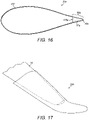
- FIG 16 is a schematic cross section through a blade tip extension 20a according to another embodiment of the present invention.
- the outer shell 28a of the tip extension 20a is formed from a single piece. This is in contrast to the previous examples where the tip extension 20 is formed from two half shells 46, 48 that are bonded together.
- an adhesive dam 57a is provided inside the tip extension 20a in the trailing edge region 58a.
- the adhesive dam 57a in this example is made from foam.
- the adhesive dam 57a substantially completely fills the trailing edge region 58a inside the tip extension 20a.
- Forming the outer shell 28a as a single piece avoids the requirement for an adhesive bond inside the tip extension 20a at the trailing edge 40a (such as the adhesive bond 65 shown in Figure 13 ).
- the adhesive dam 57a occupies substantially the entire trailing edge region 58a, it advantageously avoids any voids in this region 58a that may accumulate moisture and present problems as discussed previously in connection with voids in this region.
- the chordwise position of the leading surface 108a of the dam 57a is selected such that when the tip extension 20a is fitted to the blade, the trailing edge of the blade advantageously projects into the leading surface 108a of the dam 57a in the same way as described for previous embodiments.
- chordwise position of the leading surface 108a may be selected by suitable selecting of the chordwise width of the dam 57a. Whilst not necessarily being utilised during fabrication of the tip extension 20a, the adhesive dam 57a still provides the second, third and fourth advantages summarised above when incorporated in a tip extension 20a having an outer shell 28a formed from a single piece.
- FIG 17 shows a tip extension 20b in accordance with another embodiment of the invention.
- the tip extension 20b is curved.
- the tip extension 20b advantageously curves away from the tower in order to prevent the extended blade 18 from striking the tower in use.
- the risk of tower strike may increase when extending the length of a blade 18, so the curved tip extension 20b advantageously mitigates this risk.
- the curved tip extension 20b may be suited to fit blades that already have a curved tip.
- the curved tip extension 20b may be manufactured and attached to the blade 18 in the same way as previously described, and it should be appreciated that all of the technical features and advantages discussed above in relation to the previous embodiments apply equally to a curved tip extension such as the tip extension 20b shown in Figure 17 .
- Suitable materials may include compressible materials or materials that are softer than the materials comprising the blade trailing edge 68, thus allowing the trailing edge 68 to compress or cleave the material of the dam 57, 57a during fitting of the tip extension 20, 20a, 20b.
- the adhesive dam 57, 57a in the tip extension 20, 20a, 20b may be provided with a longitudinal channel or slot for receiving the trailing edge 68 of the blade 18, which may allow harder or less compressible materials to be used and/or which may facilitate the process of fitting the tip extension 20, 20a, 20b to the blade 18.
Landscapes
- Engineering & Computer Science (AREA)
- Mechanical Engineering (AREA)
- Life Sciences & Earth Sciences (AREA)
- Sustainable Development (AREA)
- Sustainable Energy (AREA)
- Chemical & Material Sciences (AREA)
- Combustion & Propulsion (AREA)
- General Engineering & Computer Science (AREA)
- Physics & Mathematics (AREA)
- Fluid Mechanics (AREA)
- Wind Motors (AREA)
Description
- The present invention relates generally to tip extensions for wind turbine blades, and more specifically to a method of attaching a tip extension to a wind turbine blade.
- There is a continuing desire to generate increased levels of power from existing wind power production facilities such as on-shore and off-shore wind farms. One way to achieve this is to add further wind turbines to a wind farm or to replace existing wind turbines with larger wind turbines capable of generating more power. Another way to achieve this is to increase the power production and energy capture from existing turbines, for example by replacing the blades with larger blades. However, as the blades of wind turbines are expensive components, it is often prohibitive in terms of cost to replace the blades.
- It has therefore been proposed to modify the blades of existing wind turbines by adding devices to the blades. For example, it is known to add devices to the blades to increase the dimensions of the blades. One example of this is a blade tip extension, which may be provided in the form of a sock that fits over the tip of a blade and increases the length of the blade. The provision of tip extensions increases the overall length of the blades and thus increases the swept area of the rotor, allowing the wind turbine to capture more energy from the wind.
- The installation of blade tip extensions is technically challenging. The tip extensions must be fitted accurately to the blade and attached firmly. As the devices are typically installed to wind turbine blades in the field, the process is carried out by operators working at a significant height with exposure to often harsh climate conditions. It is therefore important to develop attachment processes that are both straightforward and reliable. To this end, the tip extensions should be designed to facilitate the attachment process.
-
EP2365212A1 discloses a tip extension that is held onto a main blade by means of a vacuum. An air tight seal is provided between the tip extension and the blade surface to maintain the vacuum pressure. - Against this background, it is an object of the present invention to provide an effective and reliable method of attaching a tip extension to a wind turbine blade.
- According to a first aspect of the present invention there is provided a method of attaching a tip extension to a tip end of a wind turbine blade. The method comprises: providing a wind turbine blade having a tip end to be extended; providing a tip extension in the form of a sock; attaching one or more adhesive dams to an outer surface of the blade at the tip end and/or to an inner surface of the tip extension, the adhesive dam(s) being arranged to define one or more bond cavities between the outer surface of the blade and the inner surface of the tip extension when the tip extension is fitted to the blade; sliding the tip extension over the tip end of the blade; and bonding the tip extension to the blade by means of adhesive provided in the one or more bond cavities; wherein the one or more adhesive dams include a friction-reducing layer arranged to facilitate sliding of the tip extension over the tip end of the blade.
- The adhesive dam(s) may be applied to the outer surface of the blade prior to fitting the tip extension. Alternatively, the adhesive dams could be applied to an internal surface of the tip extension, or a combination of these options may be used. The adhesive dams serve to constrain adhesive within the bond cavities, and may also be referred to as adhesive-constraining dams.
- The adhesive dams are preferably made primarily from foam, for example PVC foam, although other suitable materials may be used. When the tip extension is fitted to the blade, the adhesive dams may be compressed slightly between the inner surface of the tip extension and the outer surface of the blade. The friction-reducing layer of the adhesive dams advantageously avoids a build up of friction occurring when the tip extension is pushed or pulled over the tip end of the blade. This allows the tip extension to slide relatively easily onto the blade and avoids the adhesive dams from being torn or dislodged or damaged during fitting.
- The method may comprise bonding the adhesive dam(s) to the outer surface of the blade. A gel coat and/or paint may be removed from the outer surface of the blade at the tip end prior to applying the adhesive dam(s).
- In the above method, the adhesive dam may comprise a strip having a friction-reducing layer. The strip is preferably made from foam, for example PVC foam, although other suitable materials may be used.
- The friction-reducing layer is preferably a layer of polytetrafluoroethylene (PTFE), although other suitable non-stick or low-friction materials may be used.
- The friction-reducing layer is preferably integral with the strip. Preferably the friction reducing layer is applied during manufacture of the strip.
- The friction-reducing layer may be provided on a first side of the strip. An adhesive layer may be provided on a second side of the strip, opposite the first side.
- There may be provided a foam tape for use in the above method, wherein the foam tape comprises an integral PTFE layer on one side. Preferably the tape comprises an integral adhesive layer on the other side. Preferably the foam is PVC foam. Preferably the tape comprises the PTFE layer on an upper side of the foam and an adhesive layer on a lower side of the foam.
- Accordingly, in preferred embodiments, the adhesive dam may comprise a foam strip, preferably PVC foam, having an integral friction-reducing layer such as a PTFE layer on one side and an integral adhesive layer on the other side.
- According to a second aspect of the present invention there is provided a wind turbine blade having a tip end, wherein one or more adhesive dams are provided on an outer surface of the blade at the tip end, the adhesive dam(s) comprising a strip having a friction-reducing layer. A tip extension is bonded to the tip end of the blade, and the one or more adhesive dams are sandwiched between the wind turbine blade and the tip extension. The adhesive dam(s) preferably at least partially define one or more bond cavities between the blade and the tip extension and wherein the bond cavities are at least partially filled with adhesive.
- Optional and advantageous features described in relation to one aspect of the invention apply equally to all aspects of the invention. Repetition of optional features and associated advantages is avoided for reasons of conciseness.
-
-
Figure 1 is a schematic view of a wind turbine having a plurality of blades fitted with tip extensions; -
Figure 2 schematically shows a tip extension fitted to a tip end of a wind turbine blade; -
Figure 3 shows first and second half shells forming the tip extension; -
Figure 4 shows the first half shell of the tip extension in isolation; -
Figure 5 shows the first and second half shells of the tip extension bonded together by adhesive; -
Figure 6 schematically illustrates a clash condition between a trailing edge of the blade and cured adhesive inside the trailing edge of the tip extension; -
Figure 7 shows adhesive dams applied to the tip end of a blade prior to fitting the tip extension; -
Figure 7a is a schematic cross-sectional view of an adhesive dam having a friction-reducing upper layer and an adhesive lower layer; -
Figure 8 shows the tip extension fitted over the tip end of the blade and shows a plurality of pre-drilled injection holes provided in the tip extension; -
Figure 9 is a schematic cross-section taken along the line 9-9 inFigure 8 ; -
Figure 10 illustrates the process of bonding the tip extension to the blade, in which adhesive is supplied through the injection holes in the tip extension; -
Figure 10a is a close-up view showing adhesive being injected through an injection hole; -
Figure 11 is a schematic cross-sectional view of a trailing edge region of a tip extension fitted to a blade, illustrating an adhesive dam provided in the trailing edge region of the tip extension and which is spaced apart from the trailing edge of the blade; -
Figure 12 schematically illustrates an alternative arrangement of adhesive dams in which an additional adhesive dam is provided near the trailing edge of the blade; -
Figures 13 and 14 schematically illustrate a preferred arrangement of the adhesive dam at the trailing edge of the tip extension, in which the trailing edge of the blade cuts into the adhesive dam; -
Figure 15 corresponds toFigure 14 and additionally shows adhesive bonds between the tip extension and the blade at the trailing edge of the blade; -
Figure 16 is a schematic cross-section through a tip extension formed as a single piece and including a foam dam filling a trailing edge region inside the tip extension; and -
Figure 17 shows a curved tip extension fitted to a tip end of a wind turbine blade. -
Figure 1 is a schematic view of a horizontalaxis wind turbine 10 according to an embodiment of the present invention. Thewind turbine 10 comprises atower 12 supporting anacelle 14. Arotor 16 is mounted to thenacelle 14. Therotor 16 comprises a plurality ofwind turbine blades 18. In this example, therotor 16 comprises threeblades 18, but in other embodiments therotor 16 may have any number ofblades 18. Eachblade 18 is retro-fitted with a blade tip extension (BTE) 20, which extends the effective length of theblade 18. -
Figure 2 is a schematic view of a windturbine blade assembly 22 comprising awind turbine blade 18 fitted with ablade tip extension 20 according to an embodiment of the present invention. Theblade tip extension 20 in this example is in the form of a sock, which fits over atip end 24 of theblade 18. Thetip end 24 of theblade 18 comprises atip 26. In some embodiments, thetip 26 may optionally be removed from theblade 18 prior to fitting thetip extension 20. Thetip extension 20 comprises anouter shell 28 defining a substantially hollow interior for receiving thetip end 24 of theblade 18. - The
tip extension 20 has aninboard end 30 and anoutboard end 32. When fitted to theblade 18, theinboard end 30 of thetip extension 20 is located closer to a root 33 (seeFigure 1 ) of theblade 18 than theoutboard end 32. Theinboard end 30 of thetip extension 20 is open to receive thetip end 24 of theblade 18 to be extended. Theoutboard end 32 of thetip extension 20 is closed and comprises atip 36, which forms the tip of the windturbine blade assembly 22 when thetip extension 20 is fitted to theblade 18. - The
outer shell 28 of thetip extension 20 extends longitudinally in a lengthwise ('spanwise') direction S between theopen root end 30 towards thetip 36, and extends transversely in a widthwise ('chordwise') direction C between aleading edge 38 and a trailingedge 40. Theouter shell 28 defines an airfoil profile in cross-section. - When fitted to the
blade 18, an inboard portion 42 (also referred to as an 'overlap portion') of thetip extension 20 overlaps thetip end 24 of theblade 18, and is bonded to theblade 18 as will be discussed in more detail later. Anoutboard portion 44 of thetip extension 20, comprising the tip-extension tip 36, serves to extend the overall length of theblade 18. - In this example the
blade tip extension 20 has an overall length of approximately three metres. Theinboard portion 42 has a length of approximately two metres, whilst theoutboard portion 44 has a length of approximately one metre. Accordingly, when fitted to an existingblade 18, thetip extension 20 extends the length of theblade 18 by approximately one metre, and provides a two-metre overlap. This size of tip extension is suitable for blades having an original length of approximately 40 metres. However, in other examples the tip extension may have other dimensions, and/or may be sized to fit blades having a different length. These dimensions are therefore exemplary only and are not intended to limit the scope of the invention. - Further details of the
tip extension 20 in terms of its construction and method of attachment to theblade 18 will now be discussed with reference to the remaining figures. - Referring to
Figure 3 , theouter shell 28 of thetip extension 20 is formed from first andsecond half shells edges blade tip extension 20. Eachhalf shell half shells - For example, a typical resin infusion process may involve arranging a number of layers of reinforcing material such as glass- or carbon-fibre fabric in the mould to form a layup. The layup may be covered with a layer of vacuum film to form a sealed region encapsulating the layup. A vacuum pump may be used to remove air from the sealed region, and resin may be admitted into the sealed region. The resin infuses between the fabric layers. The resin subsequently cures to form the finished composite shells.
- Referring to
Figure 4 , this shows thefirst half shell 46 of the tip extension.Bond regions inner surface 54 of thehalf shell 46 in theinboard portion 42 of thetip extension 20. As will be described in further detail later, when thetip extension 20 is fitted to theblade 18, theseregions tip extension 20 are bonded to corresponding bond regions defined on the outer surface of theblade 18. In this example, thebond regions inboard portion 42 of thehalf shell 46. Thebond regions half shell 46. - The
bond regions tip extension 20 is fitted to theblade 18, afirst bond region 50 overlaps a trailing edge region of theblade 18, whilst asecond bond region 52 overlaps a spar cap region of theblade 18. The first andsecond bond regions - A layer of peel ply 55 is provided in the
bond regions peel ply layer 55 may be provided as the uppermost layer in the layup when forming thehalf shell 46 such that it is exposed on theinner surface 54 of thehalf shell 46. Thepeel ply layer 55 includes a protective sheet, which is removed after the moulding process to expose a rough surface in thebond regions tip extension 20 is bonded to theblade 18. The keying surface enhances the bond strength between thetip extension 20 and theblade 18. -
Spacers 56 are provided on theinner surface 54 of thefirst half shell 46, outside thebond areas spacers 56 ensure that there is adequate space for adhesive between thebond regions blade 18 when thetip extension 20 is fitted to theblade 18. - An
adhesive dam 57 is provided on theinner surface 54 of thefirst half shell 46 in a trailingedge region 58 of thehalf shell 46 near the trailingedge 40. Theadhesive dam 57 in this example comprises a strip or tape, which is preferably made from a compressible material such as foam. Foam has particularly advantages in this context, which will be discussed in detail later. In this example, the adhesive dam is made from PVC (polyvinyl chloride) foam. ThePVC foam strip 57 has approximate dimensions of 5x10 millimetres in terms of height and width. The strip is added to thefirst half shell 46 after thehalf shell 46 is finished but before the twohalf shells PVC foam strip 57 includes an adhesive film on one side to facilitate attachment to theinner surface 54 of thefirst half shell 46. - The
adhesive dam 57 serves to contain adhesive that is used to bond together the trailingedges 40 of the first andsecond half shells tip extension 20, as discussed further below with reference toFigures 5 and 6 . Theadhesive dam 57 extends longitudinally in the spanwise direction S (seeFigure 2 ). The adhesive dam is spaced from the trailingedge 40 of thefirst half shell 46 in the chordwise direction. In this example, theadhesive dam 57 extends in the spanwise direction generally parallel to the trailingedge 40 of thefirst half shell 46, and hence it extends non-parallel to a spanwise axis S' of thefirst half shell 46. In this example, theadhesive dam 57 extends longitudinally from the near thetip 36 to near theroot 30 of thehalf shell 46. Other configurations of theadhesive dam 57 may be used in other embodiments. - Whilst not shown, the inner surface of the
second half shell 48 of thetip extension 20 is configured similarly to thefirst half shell 46 in that it also includes corresponding bond regions, peel ply in the bond regions and spacers outside of the bond regions. However, in this example, theadhesive dam 57 is associated only with thefirst half shell 46. In other examples, theadhesive dam 57 may instead be applied to thesecond half shell 48, or adhesive dams may be applied to both the first andsecond half shells half shells - Referring to
Figure 5 , this illustrates the process of bonding the first andsecond half shells tip extension 20. In this example, adhesive 60 is first applied at a plurality of discrete locations spaced along the leadingedge 38 of thefirst half shell 46. Thesecond half shell 48 is positioned into a jig and then lowered into position on top of thefirst half shell 46 such that the leading and trailingedges respective half shells half shells leading edge 38 forms a series of spot bonds between the twoshells edges 38. These spot bonds hold the twohalf shells tip extension 20 together sufficiently to allow theleading edge 38 of thetip extension 20 to be over-laminated. The over-lamination process preferably involves applying layers of prepreg glass-fibre fabric across the interface of thehalf shells leading edge 38 using hand layup. - When the
second half shell 48 is positioned on top of thefirst half shell 46, theadhesive dam 57 arranged at the trailingedge 40 of thefirst half shell 46 is preferably compressed slightly by the inner surface 62 (indicated inFigure 9 ) of thesecond half shell 48. A trailingedge bond cavity 64 is defined between the twohalf shells adhesive dam 57 and therespective trailing edges 40 of the twohalf shells edge bond cavity 64. The adhesive 65 is injected through at least onehole 66 provided in at least one of thehalf shells edge bond cavity 64. In this example, ahole 66 is provided near thetip 36 of thesecond half shell 48. The injected adhesive 65 flows longitudinally from thetip 36 towards theopen root end 30 of thetip extension 20. - The
adhesive dam 57 advantageously allows the position of the trailing edge bond line between the twohalf shells adhesive dam 57, it would not be possible to control the chordwise position of the bond line. In particular, it would not be possible to control the position of theface 67 of the adhesive 65 that faces toward the leadingedge 38 of the tip extension 20 (best shown inFigure 6 ). If the adhesive 65 was to spread too far in the chordwise direction (i.e. too far towards the leadingedge 38 of the tip extension 20) then it may prevent thetip extension 20 from fitting correctly to theblade 18. This is illustrated by way of example inFigure 6 , and discussed below. -
Figure 6 shows schematic cross sections through trailing-edge portions of ablade 18 and atip extension 20 in the case where thetip extension 20 is not provided with an adhesive dam. In this example, the absence of an adhesive dam means that the adhesive 65 has migrated too far in the chordwise direction away from the trailingedge 40 since it is not constrained by an adhesive dam. The cured adhesive 65 clashes with the trailingedge 68 of theblade 18 and prevents thetip extension 20 from fitting over theblade 18. The provision of a trailing-edge dam 57 in thetip extension 20 therefore prevents such clashes from occurring. It will be appreciated that the risk of a clash is only associated with theoverlap region 42 of thetip extension 20 and is not a problem that exists with theoutboard region 44. - Whilst the above example describes the injection of adhesive 65 at the trailing
edge 40, the trailing edge bond between the twohalf shells tip extension 20 could instead be formed by applying adhesive directly to one of thehalf shells half shells curved tip extension 20b shown inFigure 17 and discussed later) since the curved geometry of the shells does not always produce a satisfactory bond line using the conventional bonding process. - Referring now to
Figure 7 , this shows thetip end 24 of a conventionalwind turbine blade 18, which has been prepared for mounting of a tip extension. Prior to attaching the tip extension,adhesive dams 70 are provided on theouter surface 72 of theblade 18 on both the pressure and suction sides of theblade 18, although only thesuction side 73 of theblade 18 is visible inFigure 7 . Theadhesive dams 70 are bonded to theouter surface 72 of theblade 18 and are arranged to extend along pre-defined boundaries ofbond regions outer surface 70 of theblade 18. In this example, a trailingedge bond region 74 is defined near the trailingedge 68 of theblade 18 and a sparcap bond region 76 coincides with a position of a spar cap of theblade 18. It will be appreciated that the position of thesebond regions bond regions inner surface 54 of thetip extension 20, which were described previously with reference toFigure 4 . Theadhesive dams 70 applied to theouter surface 72 of theblade 18 ensure that adhesive subsequently applied to bond thetip extension 20 to theblade 18 is contained within thesebond regions - The
adhesive dams 70 may alternatively be provided inside thetip extension 20 during manufacture of thetip extension 20. However, it is advantageous to apply thesedams 70 to theblade 18 because thetip extension 20 may be in storage for some time before it is used, which may cause thedams 70 to deteriorate. By installing thesedams 70 on theblade 18 at the time of installation of thetip extension 20, it can be ensured that thedams 70 are of high quality without deterioration. - Once the
adhesive dams 70 have been applied to theouter surface 72 of theblade 18, theblade 18 is ready to receive thetip extension 20. Optionally, prior to fitting thetip extension 20, thebond regions outer surface 72 of theblade 18 may be further prepared. For example the gel coat and/or paint on theouter surface 72 of theblade 18 may be removed and thebond regions - Referring now to
Figure 8 , thetip extension 20 is inserted over the prepared tip end 24 of theblade 18. The process initially involves aligning thetip 26 of theblade 18 with theopen end 30 of thetip extension 20. Once aligned, thetip extension 20 is pulled or pushed over thetip end 24 of theblade 18 in the direction of thearrows 78, i.e. towards the root of theblade 18. - The use of conventional foam (e.g. a PVC foam strip) to form the
dams 70 makes it difficult to fit thetip extension 20 to theblade 18. This is caused by a build up of friction between thedams 70 and theinner surfaces 54, 62 (indicated inFigure 9 ) of thetip extension 20, which makes it difficult to slide thetip extension 20 over theblade 18. Lower density foam dams have been found to have a tendency to tear apart when sliding the tip extension onto theblade 18. - Preferably, the
adhesive dams 70 may be formed from or comprise materials that minimise friction between thedams 70 and thetip extension 20. In this example, and as illustrated schematically inFigure 7a , theadhesive dams 70 comprise a strip ortape 80 having a friction-reducinglayer 82 on one side. Thetape 80 may be made from foam, e.g. PVC foam. The friction-reducinglayer 82 in this example is a layer of polytetrafluoroethylene (PTFE) e.g. Teflon™. The PTFE friction-reducinglayer 82 advantageously allows thetip extension 20 to slide over theblade 18 without a build up of friction. Anadhesive layer 86 is preferably provided on the other side of thetape 80 to facilitate attachment of theadhesive dam 70 to the surface of theblade 18. - The
PTFE layer 82 is preferably and advantageously provided as an integral layer of theadhesive dam 70. For example, thePTFE layer 82 may be provided during manufacture of thedams 70. Thedams 70 are preferably manufactured in sheet form, wherein a layer of PTFE is bonded to an upper surface of a sheet of PVC foam, and a layer of adhesive may be bonded to the lower surface of the sheet. The sheet may then be slit to the required width of the tape to form thedams 70. - Whilst the
PTFE layer 82 may be applied subsequently to thedams 70, for example after thedams 70 have been manufactured or after thedams 70 have been applied to theblade 18, there is a risk of such subsequently-applied PTFE layers 82 becoming displaced or detached from thedams 70 during fitting of thetip extension 20 to theblade 18. If thePTFE layer 82 or part of it is displaced into thebond regions 74, 76 (shown inFigure 7 ) then it may act as a crack initiator. It is therefore preferable and advantageous to integrate thePTFE layer 82 into the structure of thedams 70 to avoid such problems. It also facilitates attachment of thetip extension 20 as there is no need to apply aPTFE layer 82 or other friction-reducing substances to thedams 70 during the attachment process. - When the
tip extension 20 is pulled or pushed over theblade 18, theadhesive dams 70 applied to theblade 18 become sandwiched between thetip extension 20 and theblade 18. It can be seen inFigure 8 that thetip extension 20 includes a plurality ofpre-drilled holes Figure 10 , theholes blade 18 and thetip extension 20 in order to bond thetip extension 20 to theblade 18. - In this example there are two rows of
pre-drilled holes half shell Figure 8 ). Each row extends in a longitudinal (spanwise) direction and comprises a plurality of mutually-spacedholes holes bond cavities 94, 96 (indicated inFigure 9 ) defined between theouter surface 72 of theblade 18 and theinner surfaces tip extension 20, as will be discussed in further detail below with reference toFigure 9 , which is a schematic cross-section taken along the line 9-9 inFigure 8 , i.e. through thetip end 24 of theblade 18 when overlapped by theinboard portion 42 of thetip extension 20. - Referring to
Figure 9 , when thetip extension 20 is fitted to theblade 18, anoverlap region 92 is defined between theouter surface 72 of thetip end 24 of theblade 18 and theinner surfaces inboard portion 42 of thetip extension 20. A plurality ofbond cavities overlap region 92. In this example, thebond cavities adhesive dams 70 applied to theblade 18, and which are sandwiched between theblade 18 and theinner surfaces tip extension 20. Specifically, sparcap bond cavities 94 are defined between the opposed sparcap bond regions 76 of theblade shell 18 and theinner surfaces tip extension 20, and trailingedge bond cavities 96 are defined between the opposed trailingedge bond regions 74 of theblade shell 18 and theinner surfaces tip extension 20. As shown inFigure 9 , thebond cavities leeward sides blade 18. - The spar
cap bond cavities 94 are each bound in the chordwise direction C by theadhesive dams 70 applied to thesurface 72 of theblade 18. The trailingedge bond cavities 96 are bound in the chordwise direction C by the trailing edgeadhesive dam 57 provided in thetip extension 20 and by the trailing edgeadhesive dams 70 applied to thesurface 72 of theblade 18. -
Figure 9 also shows thespacers 56, which were discussed previously with reference toFigure 4 . Thespacers 56 ensure that there is a minimum separation distance between theouter surface 72 of theblade 18 and theinner surfaces tip extension 20, so that there is sufficient space in thebond cavities spacers 56 are substantially incompressible. - Still referring to
Figure 9 , it can be seen that theholes 90 provided in the sparcap bond region 52 of thetip extension 20 communicate with the sparcap bond cavities 94, whilst theholes 91 provided in the trailingedge bond region 50 of thetip extension 20 communicate with the trailingedge bond cavities 96. - Referring now to
Figure 10 , this illustrates the process of bonding thetip extension 20 to theblade 18. The process involves injecting adhesive 98 through theholes Figure 10a , which shows adhesive 98 being injected through ahole 90a). For each bond, the adhesive 98 is first injected through thehole tip 36 of thetip extension 20. The adhesive 98 begins to fill the associatedbond cavity hole adhesive dams adjacent hole hole hole tip 36 and moving from hole-to-hole towards theroot end 30 of thetip extension 20. - As shown in
Figure 10a , theshell 28 of thetip extension 20 in this example is advantageously translucent, since it is composed of glass-fibre composite. This allows theflow front 100 of the adhesive 98 to be visually inspected during the injection process. When theflow front 100 begins to approach thenext hole 90b in the series, the injection process through thecurrent hole 90a is terminated and adhesive is injected through thatnext hole 90b. In this example, the injection through ahole 90a is terminated when the flow of adhesive is within a predetermined distance 'x' from thenext hole 90b (in this example, the predetermined distance x is approximately 25 mm), and injection through thatnext hole 90b then commences. - The process of injecting adhesive sequentially through the series of
holes tip 36 to root 30 advantageously prevents air lock offs and avoids voids forming in the bonds. In addition, stopping adhesive injection within the pre-determined distance also reduces the back pressure of adhesive, and therefore reduces the risk of breaching the adhesive dams. Theroot end 30 of thetip extension 20 is open, hence air can escape through thisopen end 30 as theadhesive flow front 100 moves generally in a longitudinal direction towards theopen root end 30. Air can also escape through the next hole in the series ofholes adhesive dams adhesive dams tip extension 20 and theblade 18 in precisely defined positions and without voids. - It was discussed above with reference to
Figure 6 that the provision of anadhesive dam 57 near the trailingedge 40 of thetip extension 20 allows the position of the bond line between the twohalf shells tip extension 20 to be precisely defined so that the possibility of thetip extension 20 clashing with theblade trailing edge 68 is avoided during attaching of thetip extension 20. Further details, functions and advantages of thisadhesive dam 57 will now be discussed with reference toFigures 11 to 14 . - Referring to
Figure 11 , this schematically illustrates one potential arrangement of theadhesive dam 57 provided in the trailingedge region 58 of the tip extension. In this example, theadhesive dam 57 is located such that when thetip extension 20 is fitted to theblade 18, there is agap 102 in the chordwise direction between theadhesive dam 57 and the trailingedge 68 of theblade 18. Whilst this position of theadhesive dam 57 avoids a clash condition, it presents certain problems. In particular, when adhesive 98 is injected into the trailingedge bond cavities 96, the adhesive 98 must flow around the trailingedge 68 of theblade 18 from theleeward side 73 to the windward side 97 (or vice versa). This inevitably causes air lock-offs, resulting in voids in the adhesive 98 in the trailingedge bond cavities 96 and leading to a sub-optimal bond at the trailingedge 68. - Referring now to
Figure 12 , this schematically illustrates a possible configuration that avoids the adhesive 98 needing to travel around the trailingedge 68 of theblade 18. In this example,additional dams 104 are provided on the pressure and suction surfaces 97, 73 of theblade 18 near the trailingedge 68. Theadditional dams 104 prevent the adhesive 98 from flowing around the trailingedge 68 of theblade 18, and hence avoid air lock-offs in the trailingedge bond cavities 96 when thetip extension 20 is bonded to theblade 18. Whilst theseadditional dams 104 prevent voids occurring in the adhesive 98 in the trailingedge bond cavities 96, they result in a relatively narrow bond line (in the chordwise direction) between theblade 18 and thetip extension 20 at the trailingedge 68 of theblade 18. Furthermore, avoid 106 is also formed between the trailingedge 68 of theblade 18 and theadhesive dam 57 in thetip extension 20. A void 106 in this position is undesirable because moisture may build up in thisvoid 106, necessitating the need for drain holes in thetip extension 20. Additionally, in the event of a lightning strike on theblade 18, air or moisture in thisvoid 106 may expand and could burst open the void 106, i.e. burst through theshell 28 of thetip extension 20. Therefore, whilst the provision of additionaladhesive dams 104 overcomes certain problems, it also presents additional ones. - Referring now to
Figure 13 , this schematically illustrates a preferred and particularly advantageous configuration of theadhesive dam 57 provided in the trailingedge region 58 of thetip extension 20. In this example, theadhesive dam 57 is advantageously made from foam. - The
adhesive dam 57 comprises a leadingsurface 108, which faces the leading edge 38 (indicated inFigure 5 ) of thetip extension 20 and a trailingsurface 110 which faces the trailingedge 40 of thetip extension 20. As discussed previously, thedam 57 is spaced apart from the trailingedge 40 such that a trailingedge cavity 64 is defined behind thedam 57, i.e. between thedam 57 and the trailingedge 40 of thetip extension 20. More specifically, thecavity 64 is defined between the trailingsurface 110 of thedam 57 and the trailingedge 40 of thetip extension 20. Thecavity 64 is filled with adhesive 65 during construction of thetip extension 20 to bond the twohalf shells outer shell 28 of thetip extension 20 together, as previously described. - The chordwise location of the
foam dam 57 in the tip extension is selected such that the trailingedge 68 of theblade 18 projects into the foam when thetip extension 20 is fitted to theblade 18. More specifically, the chordwise location of leadingsurface 108 of thedam 57 is selected such that the trailingedge 68 of theblade 18 projects into thefoam 57 when thetip extension 20 is fitted to theblade 18. The chordwise location of the leadingsurface 108 may selected by suitable selection of the chordwise position of thedam 57 and the chordwise width of thedam 57. During fitting of thetip extension 20, i.e. as thetip extension 20 slides on to theblade 18, the trailingedge 68 of theblade 18 effectively cuts into thefoam dam 57. This may involve the trailingedge 68 compressing or cleaving thedam 57. - With the trailing
edge 68 of theblade 18 projecting into thedam 57, parts of thedam 57 overlap the pressure and suction surfaces 97, 73 of theblade 18 at the trailingedge 68. In other words, the trailingedge 68 is sandwiched between parts of theadhesive dam 57. The trailingedge 68 preferably forms an interference fit with theadhesive dam 57. Theadhesive dam 57 may advantageously form an effective seal around the trailingedge 68. Theadhesive dam 57 advantageously separates the leeward and windward sides 97, 73 of theblade 18 and blocks any passageway for adhesive around the trailingedge 68 of theblade 18 thus avoiding the problems discussed above with reference toFigure 11 . - As shown in
Figure 15 , the configuration of theadhesive dam 57 shown inFigure 13 also enables a relatively wide bond 109 (in the chordwise direction) to be achieved between theblade 18 and thetip extension 20 at the trailingedge 68 of theblade 18, without the need for a void, thereby avoiding the problems discussed above with reference to the arrangement shown inFigure 12 . - In this particular example, the nominal chordwise position of the
foam dam 57 in thetip extension 20 may be selected so that the trailingedge 68 of theblade 18 cuts into thefoam 57 by approximately five millimetres, as indicated by thearrows 112 onFigure 13 . Due to manufacturing tolerances in theblade 18, theblade 18 may have a slightly wider or narrower chord than the designed dimension. For example, the chord dimension may have a tolerance of +/- five millimetres. The chordwise width W of thefoam dam 57 may be suitably selected to accommodate such manufacturing tolerances in the blade dimensions, as discussed below. - In this example, the
foam dam 57 may have a chordwise width W of approximately 10 mm, or slightly greater. Therefore, if theblade 18 has a wider chord than nominal (of up to about 5 mm) the trailingedge 68 will cut further into the foam dam 57 (as shown inFigure 14 ) yet thedam 57 will still separate the leeward and windward sides 73, 97 of theblade 18. Alternatively, if theblade 18 has a narrower chord than nominal (of up to about 5 mm) the trailingedge 68 will cut less far into thefoam 57, yet thedam 57 will still separate the leeward and windward sides 73, 97 of theblade 18. - The configuration of the
adhesive dam 57 illustrated inFigures 13 to 15 therefore presents a number of advantages. Firstly, it serves to constrain the adhesive 65 used to bond the twohalf shells tip extension 20 together, allowing the chordwise position of this bond to be defined so that thetip extension 20 fits theblade 18 without clashing (as discussed above with reference toFigure 6 ). Secondly, it accommodates manufacturing tolerances in the dimensions of theblade 18. Thirdly, it blocks the passage of adhesive 98 around the trailingedge 68 of theblade 18, thus avoiding air lock-offs, resulting in a superior bond devoid of voids between theblade 18 and thetip extension 20 at the trailingedge 68. Fourthly, it allows the chordwise width of thisbond 109 to be maximised. -
Figure 16 is a schematic cross section through ablade tip extension 20a according to another embodiment of the present invention. In this example theouter shell 28a of thetip extension 20a is formed from a single piece. This is in contrast to the previous examples where thetip extension 20 is formed from twohalf shells adhesive dam 57a is provided inside thetip extension 20a in the trailingedge region 58a. Theadhesive dam 57a in this example is made from foam. Theadhesive dam 57a substantially completely fills the trailingedge region 58a inside thetip extension 20a. - Forming the
outer shell 28a as a single piece avoids the requirement for an adhesive bond inside thetip extension 20a at the trailingedge 40a (such as theadhesive bond 65 shown inFigure 13 ). As theadhesive dam 57a occupies substantially the entiretrailing edge region 58a, it advantageously avoids any voids in thisregion 58a that may accumulate moisture and present problems as discussed previously in connection with voids in this region. The chordwise position of the leadingsurface 108a of thedam 57a is selected such that when thetip extension 20a is fitted to the blade, the trailing edge of the blade advantageously projects into the leadingsurface 108a of thedam 57a in the same way as described for previous embodiments. The chordwise position of the leadingsurface 108a may be selected by suitable selecting of the chordwise width of thedam 57a. Whilst not necessarily being utilised during fabrication of thetip extension 20a, theadhesive dam 57a still provides the second, third and fourth advantages summarised above when incorporated in atip extension 20a having anouter shell 28a formed from a single piece. -
Figure 17 shows atip extension 20b in accordance with another embodiment of the invention. In this example, thetip extension 20b is curved. When fitted to theblade 18, thetip extension 20b advantageously curves away from the tower in order to prevent theextended blade 18 from striking the tower in use. The risk of tower strike may increase when extending the length of ablade 18, so thecurved tip extension 20b advantageously mitigates this risk. Alternatively, or additionally, thecurved tip extension 20b may be suited to fit blades that already have a curved tip. Thecurved tip extension 20b may be manufactured and attached to theblade 18 in the same way as previously described, and it should be appreciated that all of the technical features and advantages discussed above in relation to the previous embodiments apply equally to a curved tip extension such as thetip extension 20b shown inFigure 17 . - The above embodiments are provided by way of example only and are not intended to limit the scope of the invention. Many modifications may be made to these examples without departing from the scope of the present invention as defined in the accompanying claims. For example, whilst the
dam tip extension blade trailing edge 68, thus allowing the trailingedge 68 to compress or cleave the material of thedam tip extension adhesive dam tip extension edge 68 of theblade 18, which may allow harder or less compressible materials to be used and/or which may facilitate the process of fitting thetip extension blade 18.
Claims (11)
- A method of attaching a tip extension (20) to a tip end of a wind turbine blade (18), the method comprising:providing a wind turbine blade (18) having a tip end (24) to be extended;providing a tip extension (20) in the form of a sock;attaching one or more adhesive dams (70) to an outer surface (72) of the blade at the tip end and/or to an inner surface (54, 62) of the tip extension (20), the adhesive dam(s) being arranged to define one or more bond cavities (94, 96) between the outer surface of the blade and the inner surface of the tip extension when the tip extension is fitted to the blade;sliding the tip extension (20) over the tip end (24) of the blade; andbonding the tip extension (20) to the blade by means of adhesive provided in the one or more bond cavities (94, 96);
characterised in thatthe one or more adhesive dams (70) include a friction-reducing layer (82) arranged to facilitate sliding of the tip extension (20) over the tip end of the blade (18). - The method of Claim 1, further comprising applying the adhesive dam(s) (70) to the outer surface (72) of the blade prior to fitting the tip extension (20).
- The method of Claim 1 or Claim 2, comprising bonding the adhesive dam(s) (70) to the outer surface (72) of the blade.
- The method of any preceding claim, further comprising removing a gel coat and/or paint from the outer surface of the blade at the tip end (24) prior to applying the adhesive dam(s) (70).
- A wind turbine blade (18) having a tip end (24), to be extended wherein one or more adhesive dams (70) are attached on an outer surface (72) of the blade at the tip end and/or to an inner surface (54, 62) of the tip extension (20), the adhesive dam(s) being arranged to define one or more bond cavities (94, 96) between the outer surface of the blade and the inner surface of the tip extension when the tip extension is fitted to the blade; wherein a tip extension (20) is bonded to the tip end (24) of the blade, and the one or more adhesive dams (70) are sandwiched between the wind turbine blade and the tip extension, characterised in that the adhesive dam(s) comprise a strip (80) having a friction-reducing layer (82) arranged to facilitate sliding of the tip extension (20) over the tip end of the blade (18).
- The wind turbine blade of Claim 5, wherein the friction-reducing layer (82) is integral with the strip (80).
- The wind turbine blade of Claim 5 or Claim 6, wherein the strip (80) is made from foam.
- The wind turbine blade of any of Claims 5 to 7, wherein the friction-reducing layer (82) is a layer of polytetrafluoroethylene (PTFE).
- The wind turbine blade of any of Claims 5 to 8, wherein the friction-reducing layer (82) is provided on a first side of the strip (80).
- The wind turbine blade of any of Claims 5 to 9, wherein an adhesive layer (86) is provided on a second side of the strip (80).
- The wind turbine blade (18) of Claim 5, wherein the adhesive dam(s) (70) at least partially define one or more bond cavities (94, 96) between the blade and the tip extension (20) and wherein the bond cavities are at least partially filled with adhesive.
Applications Claiming Priority (2)
| Application Number | Priority Date | Filing Date | Title |
|---|---|---|---|
| DKPA201670715 | 2016-09-15 | ||
| PCT/DK2017/050293 WO2018050194A1 (en) | 2016-09-15 | 2017-09-14 | Method of attaching a tip extension to a wind turbine blade |
Publications (2)
| Publication Number | Publication Date |
|---|---|
| EP3513063A1 EP3513063A1 (en) | 2019-07-24 |
| EP3513063B1 true EP3513063B1 (en) | 2022-08-17 |
Family
ID=61619832
Family Applications (1)
| Application Number | Title | Priority Date | Filing Date |
|---|---|---|---|
| EP17768976.7A Active EP3513063B1 (en) | 2016-09-15 | 2017-09-14 | Method of attaching a tip extension to a wind turbine blade and wind turbine blade |
Country Status (2)
| Country | Link |
|---|---|
| EP (1) | EP3513063B1 (en) |
| WO (1) | WO2018050194A1 (en) |
Families Citing this family (3)
| Publication number | Priority date | Publication date | Assignee | Title |
|---|---|---|---|---|
| DE102018218067B3 (en) * | 2018-10-22 | 2020-03-12 | Fraunhofer-Gesellschaft zur Förderung der angewandten Forschung e.V. | ROTOR BLADE EXTENSION |
| CN111561419A (en) * | 2020-06-11 | 2020-08-21 | 国电联合动力技术(保定)有限公司 | Design method for filling core material at rear edge of wind power blade |
| US12011771B2 (en) * | 2020-12-23 | 2024-06-18 | Bento Massahiko Koike | Method and apparatus for in situ extension of wind turbine blades |
Citations (1)
| Publication number | Priority date | Publication date | Assignee | Title |
|---|---|---|---|---|
| DE4035658A1 (en) * | 1990-11-09 | 1992-05-14 | Baedje K H Meteor Gummiwerke | Low friction sealing strip e.g. for window - has rubber substrate bonded to foamed polymer core bonded to low friction plastic film, whereby prod. can also be bent to small radius |
Family Cites Families (5)
| Publication number | Priority date | Publication date | Assignee | Title |
|---|---|---|---|---|
| US2946710A (en) * | 1956-03-08 | 1960-07-26 | Du Pont | Polytetrafluoroethylene adhesive tape |
| DE102008054323A1 (en) * | 2008-11-03 | 2010-05-12 | Energiekontor Ag | Rotor blade with blade tip extension for a wind turbine |
| WO2011067323A2 (en) * | 2009-12-02 | 2011-06-09 | Vestas Wind Systems A/S | Sectional wind turbine blade |
| DK2365212T3 (en) * | 2010-03-12 | 2016-08-15 | Siemens Ag | Device and method for rebuilding a wind turbine |
| EP2653717A1 (en) * | 2012-04-17 | 2013-10-23 | Siemens Aktiengesellschaft | Arrangement to retrofit a wind turbine blade |
-
2017
- 2017-09-14 WO PCT/DK2017/050293 patent/WO2018050194A1/en not_active Ceased
- 2017-09-14 EP EP17768976.7A patent/EP3513063B1/en active Active
Patent Citations (1)
| Publication number | Priority date | Publication date | Assignee | Title |
|---|---|---|---|---|
| DE4035658A1 (en) * | 1990-11-09 | 1992-05-14 | Baedje K H Meteor Gummiwerke | Low friction sealing strip e.g. for window - has rubber substrate bonded to foamed polymer core bonded to low friction plastic film, whereby prod. can also be bent to small radius |
Also Published As
| Publication number | Publication date |
|---|---|
| WO2018050194A1 (en) | 2018-03-22 |
| EP3513063A1 (en) | 2019-07-24 |
Similar Documents
| Publication | Publication Date | Title |
|---|---|---|
| EP3513061B1 (en) | Method and system of attaching a tip extension to a wind turbine blade | |
| EP3137291B1 (en) | A wind turbine blade and an associated manufacturing method | |
| CN111108289B (en) | Injection method and apparatus for joining and repairing shear webs | |
| EP2449254B1 (en) | Method of manufacturing a wind turbine blade comprising two members being joined by adhesion | |
| TWI537464B (en) | Wind turbine | |
| EP3274159B1 (en) | Repair of wind turbine components | |
| BR112016029061B1 (en) | TIP SYSTEM FOR A WIND TURBINE BLADE | |
| US20110103963A1 (en) | Rotor blade with drainage bore hole | |
| WO2018050194A1 (en) | Method of attaching a tip extension to a wind turbine blade | |
| CA2958507C (en) | A reinforced wind turbine blade component | |
| CN113286943B (en) | Adhesive barrier design to ensure proper adhesive flow during leaf closure | |
| EP3513062B1 (en) | Blade tip extension | |
| US20200040869A1 (en) | Method of applying a protective layer to a wind turbine rotor blade | |
| CN110709232A (en) | Method for producing a rotor blade for a wind turbine | |
| WO2025040587A1 (en) | A wind turbine blade with an aerodynamic component | |
| CN121263296A (en) | Perfusion assembly |
Legal Events
| Date | Code | Title | Description |
|---|---|---|---|
| STAA | Information on the status of an ep patent application or granted ep patent |
Free format text: STATUS: UNKNOWN |
|
| STAA | Information on the status of an ep patent application or granted ep patent |
Free format text: STATUS: THE INTERNATIONAL PUBLICATION HAS BEEN MADE |
|
| PUAI | Public reference made under article 153(3) epc to a published international application that has entered the european phase |
Free format text: ORIGINAL CODE: 0009012 |
|
| STAA | Information on the status of an ep patent application or granted ep patent |
Free format text: STATUS: REQUEST FOR EXAMINATION WAS MADE |
|
| 17P | Request for examination filed |
Effective date: 20190411 |
|
| AK | Designated contracting states |
Kind code of ref document: A1 Designated state(s): AL AT BE BG CH CY CZ DE DK EE ES FI FR GB GR HR HU IE IS IT LI LT LU LV MC MK MT NL NO PL PT RO RS SE SI SK SM TR |
|
| AX | Request for extension of the european patent |
Extension state: BA ME |
|
| DAV | Request for validation of the european patent (deleted) | ||
| DAX | Request for extension of the european patent (deleted) | ||
| STAA | Information on the status of an ep patent application or granted ep patent |
Free format text: STATUS: EXAMINATION IS IN PROGRESS |
|
| 17Q | First examination report despatched |
Effective date: 20200706 |
|
| REG | Reference to a national code |
Ref country code: DE Ref legal event code: R079 Ref document number: 602017060771 Country of ref document: DE Free format text: PREVIOUS MAIN CLASS: F03D0001060000 Ipc: B60J0010170000 |
|
| GRAP | Despatch of communication of intention to grant a patent |
Free format text: ORIGINAL CODE: EPIDOSNIGR1 |
|
| RIC1 | Information provided on ipc code assigned before grant |
Ipc: F03D 1/06 20060101ALI20220202BHEP Ipc: B60J 10/17 20160101AFI20220202BHEP |
|
| STAA | Information on the status of an ep patent application or granted ep patent |
Free format text: STATUS: GRANT OF PATENT IS INTENDED |
|
| INTG | Intention to grant announced |
Effective date: 20220310 |
|
| GRAS | Grant fee paid |
Free format text: ORIGINAL CODE: EPIDOSNIGR3 |
|
| GRAA | (expected) grant |
Free format text: ORIGINAL CODE: 0009210 |
|
| STAA | Information on the status of an ep patent application or granted ep patent |
Free format text: STATUS: THE PATENT HAS BEEN GRANTED |
|
| AK | Designated contracting states |
Kind code of ref document: B1 Designated state(s): AL AT BE BG CH CY CZ DE DK EE ES FI FR GB GR HR HU IE IS IT LI LT LU LV MC MK MT NL NO PL PT RO RS SE SI SK SM TR |
|
| REG | Reference to a national code |
Ref country code: CH Ref legal event code: EP |
|
| REG | Reference to a national code |
Ref country code: DE Ref legal event code: R096 Ref document number: 602017060771 Country of ref document: DE |
|
| REG | Reference to a national code |
Ref country code: IE Ref legal event code: FG4D |
|
| REG | Reference to a national code |
Ref country code: AT Ref legal event code: REF Ref document number: 1511953 Country of ref document: AT Kind code of ref document: T Effective date: 20220915 |
|
| REG | Reference to a national code |
Ref country code: NL Ref legal event code: MP Effective date: 20220817 |
|
| REG | Reference to a national code |
Ref country code: LT Ref legal event code: MG9D |
|
| PG25 | Lapsed in a contracting state [announced via postgrant information from national office to epo] |
Ref country code: SE Free format text: LAPSE BECAUSE OF FAILURE TO SUBMIT A TRANSLATION OF THE DESCRIPTION OR TO PAY THE FEE WITHIN THE PRESCRIBED TIME-LIMIT Effective date: 20220817 Ref country code: RS Free format text: LAPSE BECAUSE OF FAILURE TO SUBMIT A TRANSLATION OF THE DESCRIPTION OR TO PAY THE FEE WITHIN THE PRESCRIBED TIME-LIMIT Effective date: 20220817 Ref country code: PT Free format text: LAPSE BECAUSE OF FAILURE TO SUBMIT A TRANSLATION OF THE DESCRIPTION OR TO PAY THE FEE WITHIN THE PRESCRIBED TIME-LIMIT Effective date: 20221219 Ref country code: NO Free format text: LAPSE BECAUSE OF FAILURE TO SUBMIT A TRANSLATION OF THE DESCRIPTION OR TO PAY THE FEE WITHIN THE PRESCRIBED TIME-LIMIT Effective date: 20221117 Ref country code: NL Free format text: LAPSE BECAUSE OF FAILURE TO SUBMIT A TRANSLATION OF THE DESCRIPTION OR TO PAY THE FEE WITHIN THE PRESCRIBED TIME-LIMIT Effective date: 20220817 Ref country code: LV Free format text: LAPSE BECAUSE OF FAILURE TO SUBMIT A TRANSLATION OF THE DESCRIPTION OR TO PAY THE FEE WITHIN THE PRESCRIBED TIME-LIMIT Effective date: 20220817 Ref country code: LT Free format text: LAPSE BECAUSE OF FAILURE TO SUBMIT A TRANSLATION OF THE DESCRIPTION OR TO PAY THE FEE WITHIN THE PRESCRIBED TIME-LIMIT Effective date: 20220817 Ref country code: FI Free format text: LAPSE BECAUSE OF FAILURE TO SUBMIT A TRANSLATION OF THE DESCRIPTION OR TO PAY THE FEE WITHIN THE PRESCRIBED TIME-LIMIT Effective date: 20220817 |
|
| REG | Reference to a national code |
Ref country code: AT Ref legal event code: MK05 Ref document number: 1511953 Country of ref document: AT Kind code of ref document: T Effective date: 20220817 |
|
| PG25 | Lapsed in a contracting state [announced via postgrant information from national office to epo] |
Ref country code: PL Free format text: LAPSE BECAUSE OF FAILURE TO SUBMIT A TRANSLATION OF THE DESCRIPTION OR TO PAY THE FEE WITHIN THE PRESCRIBED TIME-LIMIT Effective date: 20220817 Ref country code: IS Free format text: LAPSE BECAUSE OF FAILURE TO SUBMIT A TRANSLATION OF THE DESCRIPTION OR TO PAY THE FEE WITHIN THE PRESCRIBED TIME-LIMIT Effective date: 20221217 Ref country code: HR Free format text: LAPSE BECAUSE OF FAILURE TO SUBMIT A TRANSLATION OF THE DESCRIPTION OR TO PAY THE FEE WITHIN THE PRESCRIBED TIME-LIMIT Effective date: 20220817 Ref country code: GR Free format text: LAPSE BECAUSE OF FAILURE TO SUBMIT A TRANSLATION OF THE DESCRIPTION OR TO PAY THE FEE WITHIN THE PRESCRIBED TIME-LIMIT Effective date: 20221118 |
|
| PG25 | Lapsed in a contracting state [announced via postgrant information from national office to epo] |
Ref country code: SM Free format text: LAPSE BECAUSE OF FAILURE TO SUBMIT A TRANSLATION OF THE DESCRIPTION OR TO PAY THE FEE WITHIN THE PRESCRIBED TIME-LIMIT Effective date: 20220817 Ref country code: RO Free format text: LAPSE BECAUSE OF FAILURE TO SUBMIT A TRANSLATION OF THE DESCRIPTION OR TO PAY THE FEE WITHIN THE PRESCRIBED TIME-LIMIT Effective date: 20220817 Ref country code: ES Free format text: LAPSE BECAUSE OF FAILURE TO SUBMIT A TRANSLATION OF THE DESCRIPTION OR TO PAY THE FEE WITHIN THE PRESCRIBED TIME-LIMIT Effective date: 20220817 Ref country code: DK Free format text: LAPSE BECAUSE OF FAILURE TO SUBMIT A TRANSLATION OF THE DESCRIPTION OR TO PAY THE FEE WITHIN THE PRESCRIBED TIME-LIMIT Effective date: 20220817 Ref country code: CZ Free format text: LAPSE BECAUSE OF FAILURE TO SUBMIT A TRANSLATION OF THE DESCRIPTION OR TO PAY THE FEE WITHIN THE PRESCRIBED TIME-LIMIT Effective date: 20220817 Ref country code: AT Free format text: LAPSE BECAUSE OF FAILURE TO SUBMIT A TRANSLATION OF THE DESCRIPTION OR TO PAY THE FEE WITHIN THE PRESCRIBED TIME-LIMIT Effective date: 20220817 |
|
| REG | Reference to a national code |
Ref country code: CH Ref legal event code: PL |
|
| REG | Reference to a national code |
Ref country code: DE Ref legal event code: R097 Ref document number: 602017060771 Country of ref document: DE |
|
| REG | Reference to a national code |
Ref country code: BE Ref legal event code: MM Effective date: 20220930 |
|
| PG25 | Lapsed in a contracting state [announced via postgrant information from national office to epo] |
Ref country code: SK Free format text: LAPSE BECAUSE OF FAILURE TO SUBMIT A TRANSLATION OF THE DESCRIPTION OR TO PAY THE FEE WITHIN THE PRESCRIBED TIME-LIMIT Effective date: 20220817 Ref country code: MC Free format text: LAPSE BECAUSE OF FAILURE TO SUBMIT A TRANSLATION OF THE DESCRIPTION OR TO PAY THE FEE WITHIN THE PRESCRIBED TIME-LIMIT Effective date: 20220817 Ref country code: EE Free format text: LAPSE BECAUSE OF FAILURE TO SUBMIT A TRANSLATION OF THE DESCRIPTION OR TO PAY THE FEE WITHIN THE PRESCRIBED TIME-LIMIT Effective date: 20220817 |
|
| PLBE | No opposition filed within time limit |
Free format text: ORIGINAL CODE: 0009261 |
|
| STAA | Information on the status of an ep patent application or granted ep patent |
Free format text: STATUS: NO OPPOSITION FILED WITHIN TIME LIMIT |
|
| P01 | Opt-out of the competence of the unified patent court (upc) registered |
Effective date: 20230521 |
|
| PG25 | Lapsed in a contracting state [announced via postgrant information from national office to epo] |
Ref country code: LU Free format text: LAPSE BECAUSE OF NON-PAYMENT OF DUE FEES Effective date: 20220914 Ref country code: AL Free format text: LAPSE BECAUSE OF FAILURE TO SUBMIT A TRANSLATION OF THE DESCRIPTION OR TO PAY THE FEE WITHIN THE PRESCRIBED TIME-LIMIT Effective date: 20220817 |
|
| 26N | No opposition filed |
Effective date: 20230519 |
|
| PG25 | Lapsed in a contracting state [announced via postgrant information from national office to epo] |
Ref country code: LI Free format text: LAPSE BECAUSE OF NON-PAYMENT OF DUE FEES Effective date: 20220930 Ref country code: IE Free format text: LAPSE BECAUSE OF NON-PAYMENT OF DUE FEES Effective date: 20220914 Ref country code: CH Free format text: LAPSE BECAUSE OF NON-PAYMENT OF DUE FEES Effective date: 20220930 |
|
| PG25 | Lapsed in a contracting state [announced via postgrant information from national office to epo] |
Ref country code: SI Free format text: LAPSE BECAUSE OF FAILURE TO SUBMIT A TRANSLATION OF THE DESCRIPTION OR TO PAY THE FEE WITHIN THE PRESCRIBED TIME-LIMIT Effective date: 20220817 |
|
| PG25 | Lapsed in a contracting state [announced via postgrant information from national office to epo] |
Ref country code: BE Free format text: LAPSE BECAUSE OF NON-PAYMENT OF DUE FEES Effective date: 20220930 |
|
| PG25 | Lapsed in a contracting state [announced via postgrant information from national office to epo] |
Ref country code: HU Free format text: LAPSE BECAUSE OF FAILURE TO SUBMIT A TRANSLATION OF THE DESCRIPTION OR TO PAY THE FEE WITHIN THE PRESCRIBED TIME-LIMIT; INVALID AB INITIO Effective date: 20170914 |
|
| PG25 | Lapsed in a contracting state [announced via postgrant information from national office to epo] |
Ref country code: CY Free format text: LAPSE BECAUSE OF FAILURE TO SUBMIT A TRANSLATION OF THE DESCRIPTION OR TO PAY THE FEE WITHIN THE PRESCRIBED TIME-LIMIT Effective date: 20220817 |
|
| PG25 | Lapsed in a contracting state [announced via postgrant information from national office to epo] |
Ref country code: MK Free format text: LAPSE BECAUSE OF FAILURE TO SUBMIT A TRANSLATION OF THE DESCRIPTION OR TO PAY THE FEE WITHIN THE PRESCRIBED TIME-LIMIT Effective date: 20220817 Ref country code: IT Free format text: LAPSE BECAUSE OF FAILURE TO SUBMIT A TRANSLATION OF THE DESCRIPTION OR TO PAY THE FEE WITHIN THE PRESCRIBED TIME-LIMIT Effective date: 20220817 |
|
| PG25 | Lapsed in a contracting state [announced via postgrant information from national office to epo] |
Ref country code: TR Free format text: LAPSE BECAUSE OF FAILURE TO SUBMIT A TRANSLATION OF THE DESCRIPTION OR TO PAY THE FEE WITHIN THE PRESCRIBED TIME-LIMIT Effective date: 20220817 |
|
| PG25 | Lapsed in a contracting state [announced via postgrant information from national office to epo] |
Ref country code: BG Free format text: LAPSE BECAUSE OF FAILURE TO SUBMIT A TRANSLATION OF THE DESCRIPTION OR TO PAY THE FEE WITHIN THE PRESCRIBED TIME-LIMIT Effective date: 20220817 |
|
| PG25 | Lapsed in a contracting state [announced via postgrant information from national office to epo] |
Ref country code: MT Free format text: LAPSE BECAUSE OF FAILURE TO SUBMIT A TRANSLATION OF THE DESCRIPTION OR TO PAY THE FEE WITHIN THE PRESCRIBED TIME-LIMIT Effective date: 20220817 |
|
| PGFP | Annual fee paid to national office [announced via postgrant information from national office to epo] |
Ref country code: DE Payment date: 20250926 Year of fee payment: 9 |
|
| PGFP | Annual fee paid to national office [announced via postgrant information from national office to epo] |
Ref country code: GB Payment date: 20250923 Year of fee payment: 9 |
|
| PGFP | Annual fee paid to national office [announced via postgrant information from national office to epo] |
Ref country code: FR Payment date: 20250925 Year of fee payment: 9 |