EP3513043B1 - A radial flow gas turbine generator - Google Patents
A radial flow gas turbine generator Download PDFInfo
- Publication number
- EP3513043B1 EP3513043B1 EP17771840.0A EP17771840A EP3513043B1 EP 3513043 B1 EP3513043 B1 EP 3513043B1 EP 17771840 A EP17771840 A EP 17771840A EP 3513043 B1 EP3513043 B1 EP 3513043B1
- Authority
- EP
- European Patent Office
- Prior art keywords
- gas turbine
- turbine generator
- generator
- bearings
- bearing arrangement
- Prior art date
- Legal status (The legal status is an assumption and is not a legal conclusion. Google has not performed a legal analysis and makes no representation as to the accuracy of the status listed.)
- Active
Links
Images



Classifications
-
- F—MECHANICAL ENGINEERING; LIGHTING; HEATING; WEAPONS; BLASTING
- F01—MACHINES OR ENGINES IN GENERAL; ENGINE PLANTS IN GENERAL; STEAM ENGINES
- F01D—NON-POSITIVE DISPLACEMENT MACHINES OR ENGINES, e.g. STEAM TURBINES
- F01D25/00—Component parts, details, or accessories, not provided for in, or of interest apart from, other groups
- F01D25/16—Arrangement of bearings; Supporting or mounting bearings in casings
-
- F—MECHANICAL ENGINEERING; LIGHTING; HEATING; WEAPONS; BLASTING
- F01—MACHINES OR ENGINES IN GENERAL; ENGINE PLANTS IN GENERAL; STEAM ENGINES
- F01D—NON-POSITIVE DISPLACEMENT MACHINES OR ENGINES, e.g. STEAM TURBINES
- F01D15/00—Adaptations of machines or engines for special use; Combinations of engines with devices driven thereby
- F01D15/10—Adaptations for driving, or combinations with, electric generators
-
- F—MECHANICAL ENGINEERING; LIGHTING; HEATING; WEAPONS; BLASTING
- F02—COMBUSTION ENGINES; HOT-GAS OR COMBUSTION-PRODUCT ENGINE PLANTS
- F02C—GAS-TURBINE PLANTS; AIR INTAKES FOR JET-PROPULSION PLANTS; CONTROLLING FUEL SUPPLY IN AIR-BREATHING JET-PROPULSION PLANTS
- F02C6/00—Plural gas-turbine plants; Combinations of gas-turbine plants with other apparatus; Adaptations of gas-turbine plants for special use
- F02C6/04—Gas-turbine plants providing heated or pressurised working fluid for other apparatus, e.g. without mechanical power output
- F02C6/10—Gas-turbine plants providing heated or pressurised working fluid for other apparatus, e.g. without mechanical power output supplying working fluid to a user, e.g. a chemical process, which returns working fluid to a turbine of the plant
- F02C6/12—Turbochargers, i.e. plants for augmenting mechanical power output of internal-combustion piston engines by increase of charge pressure
-
- F—MECHANICAL ENGINEERING; LIGHTING; HEATING; WEAPONS; BLASTING
- F02—COMBUSTION ENGINES; HOT-GAS OR COMBUSTION-PRODUCT ENGINE PLANTS
- F02C—GAS-TURBINE PLANTS; AIR INTAKES FOR JET-PROPULSION PLANTS; CONTROLLING FUEL SUPPLY IN AIR-BREATHING JET-PROPULSION PLANTS
- F02C3/00—Gas-turbine plants characterised by the use of combustion products as the working fluid
- F02C3/04—Gas-turbine plants characterised by the use of combustion products as the working fluid having a turbine driving a compressor
- F02C3/045—Gas-turbine plants characterised by the use of combustion products as the working fluid having a turbine driving a compressor having compressor and turbine passages in a single rotor-module
- F02C3/05—Gas-turbine plants characterised by the use of combustion products as the working fluid having a turbine driving a compressor having compressor and turbine passages in a single rotor-module the compressor and the turbine being of the radial flow type
-
- F—MECHANICAL ENGINEERING; LIGHTING; HEATING; WEAPONS; BLASTING
- F02—COMBUSTION ENGINES; HOT-GAS OR COMBUSTION-PRODUCT ENGINE PLANTS
- F02C—GAS-TURBINE PLANTS; AIR INTAKES FOR JET-PROPULSION PLANTS; CONTROLLING FUEL SUPPLY IN AIR-BREATHING JET-PROPULSION PLANTS
- F02C7/00—Features, components parts, details or accessories, not provided for in, or of interest apart form groups F02C1/00 - F02C6/00; Air intakes for jet-propulsion plants
- F02C7/08—Heating air supply before combustion, e.g. by exhaust gases
-
- F—MECHANICAL ENGINEERING; LIGHTING; HEATING; WEAPONS; BLASTING
- F16—ENGINEERING ELEMENTS AND UNITS; GENERAL MEASURES FOR PRODUCING AND MAINTAINING EFFECTIVE FUNCTIONING OF MACHINES OR INSTALLATIONS; THERMAL INSULATION IN GENERAL
- F16C—SHAFTS; FLEXIBLE SHAFTS; ELEMENTS OR CRANKSHAFT MECHANISMS; ROTARY BODIES OTHER THAN GEARING ELEMENTS; BEARINGS
- F16C2360/00—Engines or pumps
- F16C2360/23—Gas turbine engines
Definitions
- the present invention relates to gas turbine generators and particularly to a bearing arrangement for a gas turbine generator. More specifically, though not exclusively, the present invention relates to a gas turbine generator suitable for use in a range extender apparatus for a hybrid electric vehicle (HEV) or electric vehicle (EV).
- HEV hybrid electric vehicle
- EV electric vehicle
- Gas turbine engines are used in a variety of applications including the generation of electric power.
- the gas turbine engine is coupled to an electrical generator such as a direct current dynamo or alternating current alternator.
- the gas turbine and generator can be coupled indirectly to one another through a speed changing device such as a gearbox. Alternatively, the gas turbine and generator can be coupled directly so that the gas turbine and generator rotate at the same speed.
- the gas turbine compressor and turbine elements can be of the axial flow or radial flow type. Where radial flow elements are used it is typically possible to use only a single stage compressor and single stage turbine and the resulting short assembly makes it possible for these rotating elements to be mounted in an overhung arrangement with the supporting bearings adjacent to the colder compressor side.
- bearings may be provided with a lubrication system that maintains a supply of oil that both lubricates and cools the bearings. Because of the high rotating speed typical of gas turbines, correct bearing lubrication and cooling is critical to achieving adequate bearing life.
- a radial flow gas turbine generator including a shaft having a rotor of the generator, a compressor wheel and a turbine wheel of the gas turbine fixed thereto, the shaft being supported for rotation by a single bearing arrangement, characterised in that said single bearing arrangement is provided at an axial position on the shaft that is between the rotor of the generator and the compressor wheel.
- a single bearing arrangement at an intermediate position on the shaft results in portions of the shaft extending from opposing sides of the bearing arrangement. It will be understood by the skilled addressee that the portions of the shaft extending from opposing sides of the bearing arrangement are unsupported at their respective distal ends.
- the single bearing arrangement thus provides the only rotational support for the shaft.
- the use of a single bearing arrangement reduces the complexity of the gas turbine generator by eliminating the need for additional bearings at other axial locations on the shaft. The shaft is this supported at a single location by the single bearing arrangement.
- the single bearing arrangement may include one or more bearings.
- the or each bearing may be a mechanical contact bearing.
- One of said portions of the shaft carries the rotor of the generator, while the other of said portions of the shaft carries the compressor and turbine wheels.
- the rotor, compressor and turbine wheels are overhung on opposing sides of the bearing arrangement.
- the bearing arrangement may include two or more mechanical contact bearings.
- the bearings may be provided in a module or sub assembly that maintains a predetermined spatial relationship between the bearings. Such a module may facilitate the fitting and removal of the bearings as a single unit.
- the bearings may be separated within the module or sub assembly by a spacer.
- the bearings may be mounted within a module configured as a sleeve.
- the bearings may be mounted in a spaced apart relationship to one another within the sleeve.
- a resilient member in the form of a coil spring may be located between the bearings in the sleeve.
- the coil spring may be located within the sleeve such that a first end of the spring abuts on of the bearings and an opposite end of the spring abuts a seat provided on the sleeve.
- the mechanical contact bearings may be rolling element bearings which include an inner race, an outer race, and a plurality of rolling elements disposed between the inner and outer races.
- the mechanical contact bearing arrangement may be air cooled.
- the bearing arrangement may be cooled by air drawn into the generator for the purpose of cooling the generator.
- the rotor of the generator may be provided with a fan to draw air into the generator.
- the mechanical contact bearing arrangement may be cooled by air drawn into the gas turbine by the compressor wheel.
- the mechanical contact bearing arrangement may be of a self-lubricating configuration and as such eliminate the need for a separate bearing lubrication system to be provided.
- the bearings may be cooled and lubricated by an appropriately configured lubrication system.
- a method of operating a gas turbine generator as claimed in any preceding claim, the gas turbine generator having a first resonant vibration speed characterised in that the method includes the step of accelerating the gas turbine generator to an operating speed that is greater than the first resonant vibration speed.
- an electric vehicle or a hybrid electric vehicle (HEV) having a gas turbine generator of the type described above.
- the generator 10 includes a radial flow gas turbine section 12 and an electrical generation section 14.
- the gas turbine section 12 includes a compressor wheel 16 and a turbine wheel 18.
- the electrical generation section 14 includes a rotor 20 and a stator 22.
- the rotor and stator 20,22 are surrounded by a casing 23.
- the compressor and turbine wheels 16, 18 are provided with respective casings 24,26.
- the gas turbine section 12 is operable in a conventional manner which is known to those skilled in the art. Specifically, air drawn into the compressor wheel casing 24 through an annular inlet 28 thereof is compressed by the compressor wheel 16. Fuel is added to the compressed air and the fuel-air mixture is caused to combust. The expanding combustion gases pass to the turbine wheel casing 26 whereupon they impinge upon the turbine wheel 18 and cause rotation thereof. Energy may subsequently be recovered from the combustion gasses, for example via a heat exchanger. The recovered energy may be used to heat the air compressed by the compressor wheel prior to combustion.
- the electrical generation section 14 operates in a conventional manner which is known to those skilled in the art where rotation of the rotor 20 relative to the stator 22 generates electrical energy.
- the compressor and turbine wheels 16,18 and rotor 20 are coupled for rotation on a common shaft 30.
- the shaft 30 comprises a turbine shaft section 30a and a generator shaft section 30b which are connected to one another.
- the connection is effected by a threaded projection 32 of the turbine shaft section 30a being received in a correspondingly threaded recess 34 of the generator shaft section 30b. It will be appreciated by the skilled addressee that other methods of joining the shaft sections 30a,30b may be employed. Alternatively, a single piece shaft may be utilised.
- the rotor 20 is further provided with an arrangement which, in use, supplies a flow of cooling air to the electrical generation section 14.
- the arrangement is a radial cooling fan 36. It will be appreciated that other forms of arrangement may be utilised to move air in the manner described. Rotation of the cooling fan 36 causes air to be drawn into the casing 23 through apertures 25 of the casing as indicated by arrow 27. The air then passes around the stator 22, and between the stator 22 and rotor 20 as indicated by arrows 29. The air exits the casing 23 via an aperture 31 provided in the end thereof.
- the shaft 30 is supported for rotation in a bearing arrangement 38 provided in the electrical generation section casing 23.
- the bearing arrangement 38 comprises a first annular bearing 40 hereinafter referred to as the generator side bearing 40, a second annular bearing 42 hereinafter referred to as the turbine side bearing 42, an annular spacer 44 positioned intermediate the bearings 40,42, and an axial spring 46 which extends between the bearings 40,42 and surrounds the annular spacer 44.
- the bearings 40,42, spacer 44 and spring 46 are separate.
- the bearings 40,42, spacer 44 and spring 46 may be incorporated into a module or cassette which can be fitted as a single item. Such an embodiment is described below with reference to figures 5 and 6 .
- Each of the bearings 40,42 is a rolling element bearing.
- Each bearing 40,42 includes an inner race, an outer race and a plurality of rolling elements disposed between the inner and outer races.
- bearing arrangement 38 is provided at an intermediate position on the shaft 30 such that turbine shaft section 30a extends from one side of the bearing arrangement 38, and the generator shaft section 30b extends from the opposite side of the bearing arrangement 38. It will further be noted that neither the turbine shaft section 30a nor the generator shaft section 30b are supported along their respective lengths by any other bearing arrangements. It will thus be understood that both the rotor 20 of the electrical generation section 14, and the compressor and turbine wheels 16, 18 of the gas turbine section 12 are overhung with respect to the bearing arrangement 38.
- the bearing arrangement 38 By providing the bearing arrangement 38 at the aforementioned intermediate position of the shaft 30 enables the bearings 40,42 to be air cooled.
- the generator side bearing 40 is located adjacent the cooling fan 36 and is surrounded by the apertures 25 through which air is drawn by the cooling fan 36.
- the turbine side bearing 42 is located adjacent the compressor inlet 28. Both bearings 40,42 are thus provided at the respective "cool" ends of the gas turbine section 12 and electrical generation section 14.
- additional cooling of the bearing arrangement 38 may be effected by utilising the air drawn into the compressor inlet 28 as indicated by arrow 48.
- the compressor wheel 16 is provided with a plurality of through apertures 50 which extend between the compressor inlet 28 and an annular space or passages 52 defined between the compressor wheel 16 and the shaft 30. Reduced pressure before the blades of the compressor causes some of the air entering the casing 23 to be drawn towards the compressor wheel apertures 50 as indicated by arrows 54.
- Air cooling of the bearing arrangement 38 permits the use of grease or oil wick lubrication for the bearings 40,42 and thus eliminates the need for a relatively complex lubrication system that feeds oil to the bearings 40,42. Air cooling of the bearing arrangement 38 further enables self-lubricating bearings 40,42 to be used as the temperatures experienced by the bearings 40,42, in use, do not exceed those at which the lubricating medium within the bearings 40,42 degrades.
- FIG. 1 there is shown longitudinal cross-sectional view of another rotating assembly, bearing arrangement, generator rotor and gas turbine compressor and turbine generally designated 100.
- FIG. 1 Features common to the embodiment of the invention described with reference to figures 1 to 4 are identified with like reference numerals prefixed with "1".
- the bearing arrangement 138 includes two bearings 140,142 which are maintained at a required axial separation with respect to one another by a spacer 144.
- the bearings 140,142 are located within a tubular sleeve 156.
- the bore 158 of the sleeve 156 is provided with an annular seat 160 against which is located one end of a coil spring 146.
- the opposing end of the coil spring 146 abuts the bearing 140 which is proximal to the rotor 120.
- the sleeve 156 is further provided around its external periphery with a plurality of elastomeric rings 162.
- the sleeve 156 is provided four rings 162 which are provided in pairs at opposing ends of the sleeve 156.
- the function of these elastomeric rings 162 is twofold. Firstly, the rings 162 define a complaint mounting arrangement for the sleeve 156, and thus the shaft 130, within the casing 123.
- the pairs elastomeric rings 162 further serve to define an annular chamber 164 around the external periphery of the sleeve 156.
- the chamber 164 may be filled with a liquid such as oil through a port 166 in the casing 123 to damp movement of the sleeve 156 and shaft 130 in directions which are substantially perpendicular to the longitudinal centreline axis of the shaft 130.
- a gas turbine generator 10 of the type described above it must operate in such a way that harmful vibrations are not excited for any significant period of time.
- the mass and stiffness characteristics may be arranged such that the generator 10 always operates at a speed lower than the first resonant vibration speed.
- such a generator 10 may be designed to operate at a speed above one or more resonant frequencies. Such a generator 10 would typically be accelerated through resonant speeds at a sufficient rate that no significantly harmful vibrations occur.
- the double overhung configuration of the rotor, and compressor and turbine may be used in conjunction with other bearing arrangements.
- the double overhung configuration may be used in conjunction with a conventional pressurised oil feed lubrication and cooling system.
- the double overhung configuration may be used in conjunction with a lubrication system where lubricant is supplied to the bearings from a reservoir by a wick.
- the gas turbine generator of the present invention may be used on an electric vehicle (EV) or hybrid electric vehicle (HEV) as a range extender apparatus. More specifically, the gas turbine generator may be operated to produce electrical power for the purpose of recharging battery cells of the EV or HEV.
- EV electric vehicle
- HEV hybrid electric vehicle
Landscapes
- Engineering & Computer Science (AREA)
- Mechanical Engineering (AREA)
- General Engineering & Computer Science (AREA)
- Chemical & Material Sciences (AREA)
- Combustion & Propulsion (AREA)
- General Chemical & Material Sciences (AREA)
- Chemical Kinetics & Catalysis (AREA)
- Connection Of Motors, Electrical Generators, Mechanical Devices, And The Like (AREA)
- Motor Or Generator Cooling System (AREA)
- Structures Of Non-Positive Displacement Pumps (AREA)
- Supercharger (AREA)
- Turbine Rotor Nozzle Sealing (AREA)
- Control Of Turbines (AREA)
Description
- The present invention relates to gas turbine generators and particularly to a bearing arrangement for a gas turbine generator. More specifically, though not exclusively, the present invention relates to a gas turbine generator suitable for use in a range extender apparatus for a hybrid electric vehicle (HEV) or electric vehicle (EV).
- Gas turbine engines are used in a variety of applications including the generation of electric power. To generate electric power the gas turbine engine is coupled to an electrical generator such as a direct current dynamo or alternating current alternator. The gas turbine and generator can be coupled indirectly to one another through a speed changing device such as a gearbox. Alternatively, the gas turbine and generator can be coupled directly so that the gas turbine and generator rotate at the same speed. The gas turbine compressor and turbine elements can be of the axial flow or radial flow type. Where radial flow elements are used it is typically possible to use only a single stage compressor and single stage turbine and the resulting short assembly makes it possible for these rotating elements to be mounted in an overhung arrangement with the supporting bearings adjacent to the colder compressor side.
- Where the compressor, turbine and generator are directly coupled and rotate at the same speed, the resulting rotating assembly is supported by a bearing system to resist the weight, thrust and other loads inherent in the machine. In the known art for overhung direct drive gas turbine generators two bearings are used, and these bearings are disposed on either side of the generator. In such an arrangement the compressor and turbine are overhung with respect to the bearings, while the rotating elements of the generator are supported between the two bearings. Such an arrangement is described in, for example,
US 2002/0084702 . - A further feature of the known art is that the bearings may be provided with a lubrication system that maintains a supply of oil that both lubricates and cools the bearings. Because of the high rotating speed typical of gas turbines, correct bearing lubrication and cooling is critical to achieving adequate bearing life.
- Alternative solutions which eliminate the need for bearing lubrication are disclosed in, for example, prior art references
US 2006/024178 andUS 6198174 .US 2006/024178 describes the use of two air foil bearings located on the shaft on either side of the generator. A similar air foil bearing arrangement is described inUS 6198174 . - According to a first aspect of the present invention there is provided a radial flow gas turbine generator, the gas turbine generator including a shaft having a rotor of the generator, a compressor wheel and a turbine wheel of the gas turbine fixed thereto, the shaft being supported for rotation by a single bearing arrangement, characterised in that said single bearing arrangement is provided at an axial position on the shaft that is between the rotor of the generator and the compressor wheel.
- The provision of a single bearing arrangement at an intermediate position on the shaft results in portions of the shaft extending from opposing sides of the bearing arrangement. It will be understood by the skilled addressee that the portions of the shaft extending from opposing sides of the bearing arrangement are unsupported at their respective distal ends. The single bearing arrangement thus provides the only rotational support for the shaft. The use of a single bearing arrangement reduces the complexity of the gas turbine generator by eliminating the need for additional bearings at other axial locations on the shaft. The shaft is this supported at a single location by the single bearing arrangement.
- The single bearing arrangement may include one or more bearings. The or each bearing may be a mechanical contact bearing.
- One of said portions of the shaft carries the rotor of the generator, while the other of said portions of the shaft carries the compressor and turbine wheels. As such, the rotor, compressor and turbine wheels are overhung on opposing sides of the bearing arrangement.
- The bearing arrangement may include two or more mechanical contact bearings. The bearings may be provided in a module or sub assembly that maintains a predetermined spatial relationship between the bearings. Such a module may facilitate the fitting and removal of the bearings as a single unit. The bearings may be separated within the module or sub assembly by a spacer.
- The bearings may be mounted within a module configured as a sleeve. In such an embodiment the bearings may be mounted in a spaced apart relationship to one another within the sleeve. A resilient member in the form of a coil spring may be located between the bearings in the sleeve. The coil spring may be located within the sleeve such that a first end of the spring abuts on of the bearings and an opposite end of the spring abuts a seat provided on the sleeve.
- The mechanical contact bearings may be rolling element bearings which include an inner race, an outer race, and a plurality of rolling elements disposed between the inner and outer races.
- The mechanical contact bearing arrangement may be air cooled. The bearing arrangement may be cooled by air drawn into the generator for the purpose of cooling the generator. In such an embodiment, the rotor of the generator may be provided with a fan to draw air into the generator. Additionally, or alternatively, the mechanical contact bearing arrangement may be cooled by air drawn into the gas turbine by the compressor wheel.
- Where cooling of the mechanical contact bearing arrangement is achieved by air drawn into both the generator and the compressor wheel, it will be appreciated that two separate air flows over the mechanical contact bearing arrangement are provided. Each airflow flows in an opposite axial direction to the other, such that one airflow impinges upon and cools a first end of the bearing arrangement, and the other airflow impinges upon and cools an opposite second end of the bearing arrangement.
- Advantageously the mechanical contact bearing arrangement may be of a self-lubricating configuration and as such eliminate the need for a separate bearing lubrication system to be provided.
- Alternatively, the bearings may be cooled and lubricated by an appropriately configured lubrication system.
- According to a further aspect of the present invention there is provided a method of operating a gas turbine generator as claimed in any preceding claim, the gas turbine generator having a first resonant vibration speed, characterised in that the method includes the step of accelerating the gas turbine generator to an operating speed that is greater than the first resonant vibration speed.
- According to another aspect of the present invention there is provided an electric vehicle (EV) or a hybrid electric vehicle (HEV) having a gas turbine generator of the type described above.
- An embodiment of the present invention will now be described with reference to the accompanying drawings in which:
-
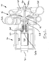
Figure 1 shows a longitudinal cross-sectional view of a gas turbine generator including a bearing arrangement according to the present invention; -
Figure 2 shows an enlarged longitudinal cross-sectional view of the bearing arrangement offigure 1 ; -
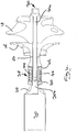
Figure 3 shows a side view of the rotating assembly of the gas turbine generator including the bearing arrangement, generator rotor, and gas turbine compressor and turbine; -
Figure 4 shows a longitudinal cross-sectional view of the rotating assembly, bearing arrangement, generator rotor and gas turbine compressor and turbine offigure 3 ; -
Figure 5 shows a longitudinal cross-sectional view of another rotating assembly, bearing arrangement, generator rotor and gas turbine compressor and turbine; and -
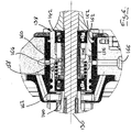
Figure 6 shows an enlarged detail of the cross-sectional view offigure 5 . - Referring firstly to
figures 1 to 4 there is shown a gas turbine generator generally designated 10. Thegenerator 10 includes a radial flowgas turbine section 12 and anelectrical generation section 14. Thegas turbine section 12 includes acompressor wheel 16 and aturbine wheel 18. Theelectrical generation section 14 includes arotor 20 and astator 22. The rotor andstator casing 23. - The compressor and
turbine wheels respective casings gas turbine section 12 is operable in a conventional manner which is known to those skilled in the art. Specifically, air drawn into thecompressor wheel casing 24 through anannular inlet 28 thereof is compressed by thecompressor wheel 16. Fuel is added to the compressed air and the fuel-air mixture is caused to combust. The expanding combustion gases pass to theturbine wheel casing 26 whereupon they impinge upon theturbine wheel 18 and cause rotation thereof. Energy may subsequently be recovered from the combustion gasses, for example via a heat exchanger. The recovered energy may be used to heat the air compressed by the compressor wheel prior to combustion. - The
electrical generation section 14 operates in a conventional manner which is known to those skilled in the art where rotation of therotor 20 relative to thestator 22 generates electrical energy. - The compressor and
turbine wheels rotor 20 are coupled for rotation on acommon shaft 30. In the embodiment shown, theshaft 30 comprises a turbine shaft section 30a and a generator shaft section 30b which are connected to one another. In the embodiment shown the connection is effected by a threadedprojection 32 of the turbine shaft section 30a being received in a correspondingly threadedrecess 34 of the generator shaft section 30b. It will be appreciated by the skilled addressee that other methods of joining the shaft sections 30a,30b may be employed. Alternatively, a single piece shaft may be utilised. - The
rotor 20 is further provided with an arrangement which, in use, supplies a flow of cooling air to theelectrical generation section 14. In the embodiment shown, the arrangement is aradial cooling fan 36. It will be appreciated that other forms of arrangement may be utilised to move air in the manner described. Rotation of the coolingfan 36 causes air to be drawn into thecasing 23 through apertures 25 of the casing as indicated byarrow 27. The air then passes around thestator 22, and between thestator 22 androtor 20 as indicated byarrows 29. The air exits thecasing 23 via anaperture 31 provided in the end thereof. - In the embodiment illustrated in the figures the
shaft 30 is supported for rotation in abearing arrangement 38 provided in the electricalgeneration section casing 23. Also in the embodiment shown, the bearingarrangement 38 comprises a first annular bearing 40 hereinafter referred to as the generator side bearing 40, a secondannular bearing 42 hereinafter referred to as the turbine side bearing 42, an annular spacer 44 positioned intermediate thebearings 40,42, and anaxial spring 46 which extends between thebearings 40,42 and surrounds the annular spacer 44. In the embodiment shown, thebearings 40,42, spacer 44 andspring 46 are separate. In an alternative embodiment thebearings 40,42, spacer 44 andspring 46 may be incorporated into a module or cassette which can be fitted as a single item. Such an embodiment is described below with reference tofigures 5 and6 . - Each of the
bearings 40,42 is a rolling element bearing. Each bearing 40,42 includes an inner race, an outer race and a plurality of rolling elements disposed between the inner and outer races. - It will be noted that bearing
arrangement 38 is provided at an intermediate position on theshaft 30 such that turbine shaft section 30a extends from one side of the bearingarrangement 38, and the generator shaft section 30b extends from the opposite side of the bearingarrangement 38. It will further be noted that neither the turbine shaft section 30a nor the generator shaft section 30b are supported along their respective lengths by any other bearing arrangements. It will thus be understood that both therotor 20 of theelectrical generation section 14, and the compressor andturbine wheels gas turbine section 12 are overhung with respect to thebearing arrangement 38. - By providing the
bearing arrangement 38 at the aforementioned intermediate position of theshaft 30 enables thebearings 40,42 to be air cooled. As can readily be seen from the figures, the generator side bearing 40 is located adjacent the coolingfan 36 and is surrounded by the apertures 25 through which air is drawn by the coolingfan 36. The turbine side bearing 42 is located adjacent thecompressor inlet 28. Bothbearings 40,42 are thus provided at the respective "cool" ends of thegas turbine section 12 andelectrical generation section 14. - Optionally, additional cooling of the bearing
arrangement 38 may be effected by utilising the air drawn into thecompressor inlet 28 as indicated by arrow 48. Thecompressor wheel 16 is provided with a plurality of throughapertures 50 which extend between thecompressor inlet 28 and an annular space orpassages 52 defined between thecompressor wheel 16 and theshaft 30. Reduced pressure before the blades of the compressor causes some of the air entering thecasing 23 to be drawn towards thecompressor wheel apertures 50 as indicated byarrows 54. - Air cooling of the bearing
arrangement 38 permits the use of grease or oil wick lubrication for thebearings 40,42 and thus eliminates the need for a relatively complex lubrication system that feeds oil to thebearings 40,42. Air cooling of the bearingarrangement 38 further enables self-lubricatingbearings 40,42 to be used as the temperatures experienced by thebearings 40,42, in use, do not exceed those at which the lubricating medium within thebearings 40,42 degrades. - Referring now to
figures 5 and6 there is shown longitudinal cross-sectional view of another rotating assembly, bearing arrangement, generator rotor and gas turbine compressor and turbine generally designated 100. Features common to the embodiment of the invention described with reference tofigures 1 to 4 are identified with like reference numerals prefixed with "1". - As before, the
bearing arrangement 138 includes two bearings 140,142 which are maintained at a required axial separation with respect to one another by a spacer 144. In contrast to thebearing arrangement 38 offigures 1 to 4 , the bearings 140,142 are located within atubular sleeve 156. The bore 158 of thesleeve 156 is provided with anannular seat 160 against which is located one end of a coil spring 146. The opposing end of the coil spring 146 abuts the bearing 140 which is proximal to therotor 120. It will be appreciated that the mounting of the bearings 140,142 with asleeve 156 enables thebearing arrangement 138 to be pre-assembled before being fitted to an appropriately sized bore of thecasing 123. - The
sleeve 156 is further provided around its external periphery with a plurality of elastomeric rings 162. In the embodiment shown thesleeve 156 is provided fourrings 162 which are provided in pairs at opposing ends of thesleeve 156. The function of theseelastomeric rings 162 is twofold. Firstly, therings 162 define a complaint mounting arrangement for thesleeve 156, and thus theshaft 130, within thecasing 123. The pairselastomeric rings 162 further serve to define an annular chamber 164 around the external periphery of thesleeve 156. The chamber 164 may be filled with a liquid such as oil through a port 166 in thecasing 123 to damp movement of thesleeve 156 andshaft 130 in directions which are substantially perpendicular to the longitudinal centreline axis of theshaft 130. - It will be understood by the skilled addressee that for a
gas turbine generator 10 of the type described above to operate reliably, it must operate in such a way that harmful vibrations are not excited for any significant period of time. Forsuch generators 10, the mass and stiffness characteristics may be arranged such that thegenerator 10 always operates at a speed lower than the first resonant vibration speed. Alternatively, such agenerator 10 may be designed to operate at a speed above one or more resonant frequencies. Such agenerator 10 would typically be accelerated through resonant speeds at a sufficient rate that no significantly harmful vibrations occur. - While the embodiment described above relates to a gas turbine generator where the bearings are air cooled and grease lubricated, it will be appreciated that the double overhung configuration of the rotor, and compressor and turbine may be used in conjunction with other bearing arrangements. For example, the double overhung configuration may be used in conjunction with a conventional pressurised oil feed lubrication and cooling system. Alternatively, the double overhung configuration may be used in conjunction with a lubrication system where lubricant is supplied to the bearings from a reservoir by a wick.
- The gas turbine generator of the present invention may be used on an electric vehicle (EV) or hybrid electric vehicle (HEV) as a range extender apparatus. More specifically, the gas turbine generator may be operated to produce electrical power for the purpose of recharging battery cells of the EV or HEV.
Claims (15)
- A radial flow gas turbine generator (10), the gas turbine generator (10) including a shaft (30,130), an electrical generation section (14) including a rotor (20,120) and a stator (22), a radial flow gas turbine section (12) including a compressor wheel (16,116) and a turbine wheel (18,118) fixed thereto, the shaft (30,130) being supported for rotation by a single bearing arrangement (38,138), characterised in that said single bearing arrangement (38,138) is provided at an axial position on the shaft (30,130) that is between the rotor (20,120) and the compressor wheel (16,116).
- A gas turbine generator (10) as claimed in claim 1 wherein the single bearing arrangement (38,138) includes two or more mechanical contact bearings (40,42,140,142) and more specifically rolling element bearings.
- A gas turbine generator (10) as claimed in claim 2 wherein the bearings (140,142) of the bearing arrangement are provided in a module that maintains a predetermined spatial relationship between the bearings (140,142).
- A gas turbine generator (10) as claimed in claim 3 wherein the bearings (140,142) are mounted within a sleeve (156).
- A gas turbine generator (10) as claimed in claim 4 wherein the bearings (140,142) are mounted in a spaced apart relationship to one another within the sleeve (156).
- A gas turbine generator (10) as claimed in claim 5 wherein a resilient member (146) is located between the bearings (140,142) in the sleeve (156), and further wherein the resilient member (146) is a coil spring.
- A gas turbine generator (10) as claimed in claim 6 wherein the coil spring is located within the sleeve (156) such that a first end of the spring abuts one of the bearings (140) and an opposite end of the spring abuts a seat (160) provided on the sleeve (156).
- A gas turbine generator (10) as claimed in any preceding claim wherein the bearing arrangement (38,138) is air cooled.
- A gas turbine generator (10) as claimed in claim 8 wherein the bearing arrangement (38,138) is cooled by air drawn into the generator (10) for the purpose of cooling the generator (10).
- A gas turbine generator (10) as claimed in claim 9 wherein the rotor (20,120) of the generator (10) is provided with an arrangement to draw air into the generator.
- A gas turbine generator (10) as claimed in any of claims 8 to 10 wherein the bearing arrangement (38,138) is cooled by air drawn into the gas turbine (12) by the compressor wheel (16,116).
- A gas turbine generator (10) as claimed in any preceding claim wherein the bearing arrangement (38,138) is one of self-lubricating, and lubricated by an oil wick system.
- A gas turbine generator (10) as claimed in any of claims 1 to 7 wherein the bearing arrangement (38,138) is cooled and lubricated by an appropriately configured recirculating lubrication system.
- A method of operating a gas turbine generator (10) as claimed in any preceding claim, the gas turbine generator (10) having a first resonant vibration speed, characterised in that the method includes the step of accelerating the gas turbine generator (10) to an operating speed that is greater than the first resonant vibration speed.
- A hybrid electric vehicle (HEV) or an electric vehicle (EV) including a gas turbine generator (10) as claimed in any of claims 1 to 13.
Priority Applications (2)
| Application Number | Priority Date | Filing Date | Title |
|---|---|---|---|
| HRP20211552TT HRP20211552T1 (en) | 2016-09-13 | 2017-09-13 | A radial flow gas turbine generator |
| PL17771840T PL3513043T3 (en) | 2016-09-13 | 2017-09-13 | A radial flow gas turbine generator |
Applications Claiming Priority (2)
| Application Number | Priority Date | Filing Date | Title |
|---|---|---|---|
| GBGB1615491.6A GB201615491D0 (en) | 2016-09-13 | 2016-09-13 | Improvements in or relating to gas turbine generators |
| PCT/GB2017/052692 WO2018051080A1 (en) | 2016-09-13 | 2017-09-13 | Improvements in or relating to gas turbine generators |
Publications (2)
| Publication Number | Publication Date |
|---|---|
| EP3513043A1 EP3513043A1 (en) | 2019-07-24 |
| EP3513043B1 true EP3513043B1 (en) | 2021-07-07 |
Family
ID=57234550
Family Applications (1)
| Application Number | Title | Priority Date | Filing Date |
|---|---|---|---|
| EP17771840.0A Active EP3513043B1 (en) | 2016-09-13 | 2017-09-13 | A radial flow gas turbine generator |
Country Status (10)
| Country | Link |
|---|---|
| US (1) | US11125103B2 (en) |
| EP (1) | EP3513043B1 (en) |
| JP (3) | JP2019526750A (en) |
| CN (1) | CN109964007B (en) |
| ES (1) | ES2893224T3 (en) |
| GB (1) | GB201615491D0 (en) |
| HR (1) | HRP20211552T1 (en) |
| HU (1) | HUE056819T2 (en) |
| PL (1) | PL3513043T3 (en) |
| WO (1) | WO2018051080A1 (en) |
Families Citing this family (6)
| Publication number | Priority date | Publication date | Assignee | Title |
|---|---|---|---|---|
| FR3105298B1 (en) * | 2019-12-20 | 2021-12-03 | Safran Helicopter Engines | AIRCRAFT TURBOGENERATOR, INCLUDING AN IMPROVED OIL SYSTEM |
| WO2021144002A1 (en) * | 2020-01-13 | 2021-07-22 | Bladon Jets Holdings Limited | Monolithic rotor and compressor wheel |
| US11333039B2 (en) * | 2020-03-13 | 2022-05-17 | Raytheon Technologies Corporation | Modular bearing compartment |
| CA3121084A1 (en) * | 2020-06-22 | 2021-12-22 | Galileo Technologies Corporation | Microturbine and method of manufacture |
| JP7554166B2 (en) * | 2021-08-10 | 2024-09-19 | 本田技研工業株式会社 | Combined Power System |
| JP7556833B2 (en) * | 2021-08-10 | 2024-09-26 | 本田技研工業株式会社 | Combined Power System |
Family Cites Families (34)
| Publication number | Priority date | Publication date | Assignee | Title |
|---|---|---|---|---|
| GB669732A (en) * | 1946-01-21 | 1952-04-09 | Alfred Buechi | Improvements in or relating to rotary bearing arrangements |
| JPS6141420Y2 (en) * | 1979-11-26 | 1986-11-25 | ||
| JPS5680663A (en) | 1979-12-05 | 1981-07-02 | Hitachi Ltd | Absorption type heating apparatus |
| US4350912A (en) * | 1980-03-03 | 1982-09-21 | Emerson Electric Co. | Wick lubrication system for self-aligning bearing |
| FR2504992B1 (en) * | 1981-04-30 | 1986-11-14 | Valbrev | COMBINATION OF A COMPRESSION OR RELAXATION TURBO-MACHINE AND AN ELECTRIC MOTOR |
| JPS59131597U (en) * | 1983-02-22 | 1984-09-04 | 株式会社島津製作所 | Turbo molecular pump lubrication system |
| JP2654433B2 (en) | 1985-11-12 | 1997-09-17 | 株式会社 半導体エネルギー研究所 | Silicon semiconductor fabrication method |
| JPS6117430U (en) * | 1984-07-09 | 1986-01-31 | 石川島播磨重工業株式会社 | Turbocharger bearing compartment |
| JPH0351546Y2 (en) * | 1986-01-07 | 1991-11-06 | ||
| JPS63181637A (en) | 1987-01-23 | 1988-07-26 | Nippon Denso Co Ltd | Ac generator for vehicle |
| JP3687693B2 (en) * | 1995-11-21 | 2005-08-24 | 株式会社安川電機 | Electric motor |
| GB2324913A (en) * | 1997-04-02 | 1998-11-04 | Aisin Seiki | Magnetic shielding in high speed turbo alternator/motor |
| EP0992696B1 (en) * | 1997-07-01 | 2007-02-28 | JTEKT Corporation | Bearing retainer of synthetic resin, method of manufacturing the same, and roller bearing |
| TW390936B (en) | 1997-12-20 | 2000-05-21 | Allied Signal Inc | Microturbine power generating system |
| US6023135A (en) | 1998-05-18 | 2000-02-08 | Capstone Turbine Corporation | Turbogenerator/motor control system |
| DE19849094C2 (en) * | 1998-10-24 | 2003-04-10 | Prec Motors Deutsche Minebea G | Spindle motor with magnetic seal |
| US6657332B2 (en) | 2000-10-30 | 2003-12-02 | Capstone Turbine Corporation | Turbogenerator cooling system |
| JP2003120214A (en) | 2001-10-05 | 2003-04-23 | Kawasaki Heavy Ind Ltd | Gas turbine equipment |
| US7025579B2 (en) * | 2001-10-16 | 2006-04-11 | Innovative Turbo Systems Corporation | Bearing system for high-speed rotating machinery |
| JP2003307103A (en) | 2002-04-15 | 2003-10-31 | Ebara Corp | Fluid machine |
| US7012346B2 (en) * | 2003-03-07 | 2006-03-14 | Resmed Limited | Low profile d.c. brushless motor for an impeller mechanism or the like |
| KR101025773B1 (en) | 2004-07-30 | 2011-04-04 | 삼성테크윈 주식회사 | Turbogenerator Apparatus and Fuel Cell System Equipped with the Turbogenerator Apparatus |
| JP5071150B2 (en) * | 2008-02-26 | 2012-11-14 | 株式会社ジェイテクト | Bearing device for turbocharger |
| BRPI0919983A2 (en) | 2009-01-14 | 2015-12-15 | Amsc Windtec Gmbh | nacelle of a wind power converter, method of mounting a nacelle of a wind power converter and generator |
| GB2474344B (en) * | 2009-10-06 | 2016-01-27 | Cummins Ltd | Turbomachine |
| DE102009053102B4 (en) * | 2009-11-13 | 2013-03-28 | Continental Automotive Gmbh | Turbocharger having a thrust bearing arrangement for a shaft of the turbocharger |
| EP2333934B1 (en) * | 2009-12-08 | 2016-07-20 | Siemens Aktiengesellschaft | Arrangement to ensure an air gap in an electric machine |
| JP5606221B2 (en) * | 2010-08-31 | 2014-10-15 | ミネベア株式会社 | Preloading device for rolling ball bearing and motor having the preloading device |
| JP5804269B2 (en) * | 2012-01-20 | 2015-11-04 | 日本電産株式会社 | motor |
| WO2013163045A1 (en) * | 2012-04-26 | 2013-10-31 | General Electric Company | System and method of recirculating exhaust gas for use in a plurality of flow paths in a gas turbine engine |
| CN104235031A (en) * | 2013-06-19 | 2014-12-24 | 重庆美的通用制冷设备有限公司 | Cantilever Multistage Compressor |
| CA2890668A1 (en) * | 2014-05-07 | 2015-11-07 | Advantage Products Inc. | Self-aligning shaft assembly |
| US20160047303A1 (en) * | 2014-08-15 | 2016-02-18 | General Electric Company | Power train architectures with mono-type low-loss bearings and low-density materials |
| CN105889325B (en) | 2015-05-19 | 2018-10-26 | 罗立峰 | A kind of small miniature gas turbine generator |
-
2016
- 2016-09-13 GB GBGB1615491.6A patent/GB201615491D0/en not_active Ceased
-
2017
- 2017-09-13 WO PCT/GB2017/052692 patent/WO2018051080A1/en not_active Ceased
- 2017-09-13 PL PL17771840T patent/PL3513043T3/en unknown
- 2017-09-13 US US16/332,881 patent/US11125103B2/en active Active
- 2017-09-13 JP JP2019535988A patent/JP2019526750A/en active Pending
- 2017-09-13 HR HRP20211552TT patent/HRP20211552T1/en unknown
- 2017-09-13 CN CN201780069954.XA patent/CN109964007B/en active Active
- 2017-09-13 EP EP17771840.0A patent/EP3513043B1/en active Active
- 2017-09-13 HU HUE17771840A patent/HUE056819T2/en unknown
- 2017-09-13 ES ES17771840T patent/ES2893224T3/en active Active
-
2022
- 2022-07-29 JP JP2022121269A patent/JP2022163102A/en active Pending
-
2024
- 2024-08-30 JP JP2024148242A patent/JP2024164250A/en active Pending
Non-Patent Citations (1)
| Title |
|---|
| None * |
Also Published As
| Publication number | Publication date |
|---|---|
| CN109964007A (en) | 2019-07-02 |
| US11125103B2 (en) | 2021-09-21 |
| HRP20211552T1 (en) | 2021-12-24 |
| JP2019526750A (en) | 2019-09-19 |
| JP2022163102A (en) | 2022-10-25 |
| CN109964007B (en) | 2021-12-28 |
| ES2893224T3 (en) | 2022-02-08 |
| EP3513043A1 (en) | 2019-07-24 |
| GB201615491D0 (en) | 2016-10-26 |
| WO2018051080A1 (en) | 2018-03-22 |
| JP2024164250A (en) | 2024-11-26 |
| HUE056819T2 (en) | 2022-03-28 |
| US20190360352A1 (en) | 2019-11-28 |
| PL3513043T3 (en) | 2022-01-03 |
Similar Documents
| Publication | Publication Date | Title |
|---|---|---|
| EP3513043B1 (en) | A radial flow gas turbine generator | |
| US5921683A (en) | Bearing arrangement for air cycle machine | |
| US9548639B2 (en) | Power generation unit of integrated gearbox design for aircraft engine | |
| EP2657463B1 (en) | Oil scoop manifold | |
| US10233762B2 (en) | Cooled seal assembly for arranging between a stator and a rotor | |
| US9006942B2 (en) | Generator main stator back-iron cooling sleeve | |
| JP2012524514A (en) | Integrated brushless starter / generator system | |
| CN103119255B (en) | The non-lubricated framework of turboaxle motor | |
| EP4115059B1 (en) | A power generation system | |
| JP2017048781A (en) | Hydrodynamic seals in bearing compartments of gas turbine engines | |
| KR20090009255A (en) | Electric supercharger | |
| US12203539B2 (en) | Compact accessory gearbox comprising an integrated electric machine | |
| US12603551B2 (en) | Hybrid liquid and air cooling of high-power permanent magnet machine rotor | |
| JP2022157733A (en) | compound power system | |
| US6887038B2 (en) | Methods and apparatus to facilitate sealing between rotating turbine shafts | |
| US20230120797A1 (en) | Lubrication system for turbine engine electric machine | |
| JP2008519580A (en) | Electromechanical equipment | |
| US7753646B1 (en) | Systems and methods for cooling bearings | |
| JP2004340014A (en) | Turbine generator | |
| EP2594766B1 (en) | A gas turbine engine comprising a permanent magnet alternator with integrated cooling fan | |
| US20200095943A1 (en) | Exoskeletal Gas Turbine Engine |
Legal Events
| Date | Code | Title | Description |
|---|---|---|---|
| REG | Reference to a national code |
Ref country code: HR Ref legal event code: TUEP Ref document number: P20211552T Country of ref document: HR |
|
| STAA | Information on the status of an ep patent application or granted ep patent |
Free format text: STATUS: UNKNOWN |
|
| STAA | Information on the status of an ep patent application or granted ep patent |
Free format text: STATUS: THE INTERNATIONAL PUBLICATION HAS BEEN MADE |
|
| PUAI | Public reference made under article 153(3) epc to a published international application that has entered the european phase |
Free format text: ORIGINAL CODE: 0009012 |
|
| STAA | Information on the status of an ep patent application or granted ep patent |
Free format text: STATUS: REQUEST FOR EXAMINATION WAS MADE |
|
| 17P | Request for examination filed |
Effective date: 20190312 |
|
| AK | Designated contracting states |
Kind code of ref document: A1 Designated state(s): AL AT BE BG CH CY CZ DE DK EE ES FI FR GB GR HR HU IE IS IT LI LT LU LV MC MK MT NL NO PL PT RO RS SE SI SK SM TR |
|
| AX | Request for extension of the european patent |
Extension state: BA ME |
|
| DAV | Request for validation of the european patent (deleted) | ||
| DAX | Request for extension of the european patent (deleted) | ||
| STAA | Information on the status of an ep patent application or granted ep patent |
Free format text: STATUS: EXAMINATION IS IN PROGRESS |
|
| 17Q | First examination report despatched |
Effective date: 20200213 |
|
| RIN1 | Information on inventor provided before grant (corrected) |
Inventor name: CARPENTER, NICHOLAS Inventor name: WILKSCH, MARK Inventor name: HERRING, SCOTT |
|
| GRAP | Despatch of communication of intention to grant a patent |
Free format text: ORIGINAL CODE: EPIDOSNIGR1 |
|
| STAA | Information on the status of an ep patent application or granted ep patent |
Free format text: STATUS: GRANT OF PATENT IS INTENDED |
|
| INTG | Intention to grant announced |
Effective date: 20210129 |
|
| GRAS | Grant fee paid |
Free format text: ORIGINAL CODE: EPIDOSNIGR3 |
|
| GRAA | (expected) grant |
Free format text: ORIGINAL CODE: 0009210 |
|
| STAA | Information on the status of an ep patent application or granted ep patent |
Free format text: STATUS: THE PATENT HAS BEEN GRANTED |
|
| AK | Designated contracting states |
Kind code of ref document: B1 Designated state(s): AL AT BE BG CH CY CZ DE DK EE ES FI FR GB GR HR HU IE IS IT LI LT LU LV MC MK MT NL NO PL PT RO RS SE SI SK SM TR |
|
| REG | Reference to a national code |
Ref country code: GB Ref legal event code: FG4D |
|
| REG | Reference to a national code |
Ref country code: AT Ref legal event code: REF Ref document number: 1408782 Country of ref document: AT Kind code of ref document: T Effective date: 20210715 |
|
| REG | Reference to a national code |
Ref country code: DE Ref legal event code: R096 Ref document number: 602017041704 Country of ref document: DE |
|
| REG | Reference to a national code |
Ref country code: IE Ref legal event code: FG4D |
|
| REG | Reference to a national code |
Ref country code: LT Ref legal event code: MG9D |
|
| REG | Reference to a national code |
Ref country code: NL Ref legal event code: FP |
|
| REG | Reference to a national code |
Ref country code: HR Ref legal event code: ODRP Ref document number: P20211552T Country of ref document: HR Payment date: 20211004 Year of fee payment: 5 |
|
| REG | Reference to a national code |
Ref country code: AT Ref legal event code: MK05 Ref document number: 1408782 Country of ref document: AT Kind code of ref document: T Effective date: 20210707 |
|
| REG | Reference to a national code |
Ref country code: HR Ref legal event code: T1PR Ref document number: P20211552 Country of ref document: HR |
|
| PG25 | Lapsed in a contracting state [announced via postgrant information from national office to epo] |
Ref country code: SE Free format text: LAPSE BECAUSE OF FAILURE TO SUBMIT A TRANSLATION OF THE DESCRIPTION OR TO PAY THE FEE WITHIN THE PRESCRIBED TIME-LIMIT Effective date: 20210707 Ref country code: RS Free format text: LAPSE BECAUSE OF FAILURE TO SUBMIT A TRANSLATION OF THE DESCRIPTION OR TO PAY THE FEE WITHIN THE PRESCRIBED TIME-LIMIT Effective date: 20210707 Ref country code: LT Free format text: LAPSE BECAUSE OF FAILURE TO SUBMIT A TRANSLATION OF THE DESCRIPTION OR TO PAY THE FEE WITHIN THE PRESCRIBED TIME-LIMIT Effective date: 20210707 Ref country code: AT Free format text: LAPSE BECAUSE OF FAILURE TO SUBMIT A TRANSLATION OF THE DESCRIPTION OR TO PAY THE FEE WITHIN THE PRESCRIBED TIME-LIMIT Effective date: 20210707 Ref country code: BG Free format text: LAPSE BECAUSE OF FAILURE TO SUBMIT A TRANSLATION OF THE DESCRIPTION OR TO PAY THE FEE WITHIN THE PRESCRIBED TIME-LIMIT Effective date: 20211007 Ref country code: NO Free format text: LAPSE BECAUSE OF FAILURE TO SUBMIT A TRANSLATION OF THE DESCRIPTION OR TO PAY THE FEE WITHIN THE PRESCRIBED TIME-LIMIT Effective date: 20211007 Ref country code: PT Free format text: LAPSE BECAUSE OF FAILURE TO SUBMIT A TRANSLATION OF THE DESCRIPTION OR TO PAY THE FEE WITHIN THE PRESCRIBED TIME-LIMIT Effective date: 20211108 Ref country code: FI Free format text: LAPSE BECAUSE OF FAILURE TO SUBMIT A TRANSLATION OF THE DESCRIPTION OR TO PAY THE FEE WITHIN THE PRESCRIBED TIME-LIMIT Effective date: 20210707 |
|
| REG | Reference to a national code |
Ref country code: ES Ref legal event code: FG2A Ref document number: 2893224 Country of ref document: ES Kind code of ref document: T3 Effective date: 20220208 |
|
| PG25 | Lapsed in a contracting state [announced via postgrant information from national office to epo] |
Ref country code: LV Free format text: LAPSE BECAUSE OF FAILURE TO SUBMIT A TRANSLATION OF THE DESCRIPTION OR TO PAY THE FEE WITHIN THE PRESCRIBED TIME-LIMIT Effective date: 20210707 Ref country code: GR Free format text: LAPSE BECAUSE OF FAILURE TO SUBMIT A TRANSLATION OF THE DESCRIPTION OR TO PAY THE FEE WITHIN THE PRESCRIBED TIME-LIMIT Effective date: 20211008 |
|
| REG | Reference to a national code |
Ref country code: DE Ref legal event code: R081 Ref document number: 602017041704 Country of ref document: DE Owner name: DELTA COSWORTH LIMITED, GB Free format text: FORMER OWNER: DELTA MOTORSPORT LIMITED, NORTHAMPTON, GB |
|
| REG | Reference to a national code |
Ref country code: HU Ref legal event code: AG4A Ref document number: E056819 Country of ref document: HU |
|
| REG | Reference to a national code |
Ref country code: DE Ref legal event code: R097 Ref document number: 602017041704 Country of ref document: DE |
|
| REG | Reference to a national code |
Ref country code: NL Ref legal event code: HC Owner name: DELTA COSWORTH LIMITED; GB Free format text: DETAILS ASSIGNMENT: CHANGE OF OWNER(S), CHANGE OF OWNER(S) NAME; FORMER OWNER NAME: DELTA MOTORSPORT LIMITED Effective date: 20220308 |
|
| REG | Reference to a national code |
Ref country code: BE Ref legal event code: HC Owner name: DELTA COSWORTH LIMITED; GB Free format text: DETAILS ASSIGNMENT: CHANGE OF OWNER(S), CHANGE OF OWNER(S) NAME; FORMER OWNER NAME: DELTA MOTORSPORT LIMITED Effective date: 20220325 |
|
| PG25 | Lapsed in a contracting state [announced via postgrant information from national office to epo] |
Ref country code: DK Free format text: LAPSE BECAUSE OF FAILURE TO SUBMIT A TRANSLATION OF THE DESCRIPTION OR TO PAY THE FEE WITHIN THE PRESCRIBED TIME-LIMIT Effective date: 20210707 |
|
| REG | Reference to a national code |
Ref country code: CH Ref legal event code: PL |
|
| PLBE | No opposition filed within time limit |
Free format text: ORIGINAL CODE: 0009261 |
|
| STAA | Information on the status of an ep patent application or granted ep patent |
Free format text: STATUS: NO OPPOSITION FILED WITHIN TIME LIMIT |
|
| REG | Reference to a national code |
Ref country code: HU Ref legal event code: HC9C Owner name: DELTA COSWORTH LIMITED, GB Free format text: FORMER OWNER(S): DELTA MOTORSPORT LIMITED, GB |
|
| PG25 | Lapsed in a contracting state [announced via postgrant information from national office to epo] |
Ref country code: SM Free format text: LAPSE BECAUSE OF FAILURE TO SUBMIT A TRANSLATION OF THE DESCRIPTION OR TO PAY THE FEE WITHIN THE PRESCRIBED TIME-LIMIT Effective date: 20210707 Ref country code: SK Free format text: LAPSE BECAUSE OF FAILURE TO SUBMIT A TRANSLATION OF THE DESCRIPTION OR TO PAY THE FEE WITHIN THE PRESCRIBED TIME-LIMIT Effective date: 20210707 Ref country code: RO Free format text: LAPSE BECAUSE OF FAILURE TO SUBMIT A TRANSLATION OF THE DESCRIPTION OR TO PAY THE FEE WITHIN THE PRESCRIBED TIME-LIMIT Effective date: 20210707 Ref country code: MC Free format text: LAPSE BECAUSE OF FAILURE TO SUBMIT A TRANSLATION OF THE DESCRIPTION OR TO PAY THE FEE WITHIN THE PRESCRIBED TIME-LIMIT Effective date: 20210707 Ref country code: EE Free format text: LAPSE BECAUSE OF FAILURE TO SUBMIT A TRANSLATION OF THE DESCRIPTION OR TO PAY THE FEE WITHIN THE PRESCRIBED TIME-LIMIT Effective date: 20210707 Ref country code: AL Free format text: LAPSE BECAUSE OF FAILURE TO SUBMIT A TRANSLATION OF THE DESCRIPTION OR TO PAY THE FEE WITHIN THE PRESCRIBED TIME-LIMIT Effective date: 20210707 |
|
| REG | Reference to a national code |
Ref country code: HR Ref legal event code: PNAN Ref document number: P20211552 Country of ref document: HR Owner name: DELTA COSWORTH LIMITED, GB |
|
| 26N | No opposition filed |
Effective date: 20220408 |
|
| REG | Reference to a national code |
Ref country code: ES Ref legal event code: PC2A Owner name: DELTA COSWORTH LIMITED Effective date: 20220629 |
|
| PG25 | Lapsed in a contracting state [announced via postgrant information from national office to epo] |
Ref country code: LU Free format text: LAPSE BECAUSE OF NON-PAYMENT OF DUE FEES Effective date: 20210913 Ref country code: IE Free format text: LAPSE BECAUSE OF NON-PAYMENT OF DUE FEES Effective date: 20210913 |
|
| PG25 | Lapsed in a contracting state [announced via postgrant information from national office to epo] |
Ref country code: LI Free format text: LAPSE BECAUSE OF NON-PAYMENT OF DUE FEES Effective date: 20210930 Ref country code: CH Free format text: LAPSE BECAUSE OF NON-PAYMENT OF DUE FEES Effective date: 20210930 |
|
| REG | Reference to a national code |
Ref country code: HR Ref legal event code: ODRP Ref document number: P20211552 Country of ref document: HR Payment date: 20220907 Year of fee payment: 6 |
|
| PG25 | Lapsed in a contracting state [announced via postgrant information from national office to epo] |
Ref country code: CY Free format text: LAPSE BECAUSE OF FAILURE TO SUBMIT A TRANSLATION OF THE DESCRIPTION OR TO PAY THE FEE WITHIN THE PRESCRIBED TIME-LIMIT Effective date: 20210707 |
|
| REG | Reference to a national code |
Ref country code: HR Ref legal event code: ODRP Ref document number: P20211552 Country of ref document: HR Payment date: 20230901 Year of fee payment: 7 |
|
| PG25 | Lapsed in a contracting state [announced via postgrant information from national office to epo] |
Ref country code: MK Free format text: LAPSE BECAUSE OF FAILURE TO SUBMIT A TRANSLATION OF THE DESCRIPTION OR TO PAY THE FEE WITHIN THE PRESCRIBED TIME-LIMIT Effective date: 20210707 |
|
| REG | Reference to a national code |
Ref country code: HR Ref legal event code: ODRP Ref document number: P20211552 Country of ref document: HR Payment date: 20240905 Year of fee payment: 8 |
|
| PG25 | Lapsed in a contracting state [announced via postgrant information from national office to epo] |
Ref country code: MT Free format text: LAPSE BECAUSE OF FAILURE TO SUBMIT A TRANSLATION OF THE DESCRIPTION OR TO PAY THE FEE WITHIN THE PRESCRIBED TIME-LIMIT Effective date: 20210707 |
|
| PGFP | Annual fee paid to national office [announced via postgrant information from national office to epo] |
Ref country code: DE Payment date: 20240918 Year of fee payment: 8 Ref country code: HR Payment date: 20240905 Year of fee payment: 8 |
|
| PGFP | Annual fee paid to national office [announced via postgrant information from national office to epo] |
Ref country code: GB Payment date: 20240917 Year of fee payment: 8 |
|
| PGFP | Annual fee paid to national office [announced via postgrant information from national office to epo] |
Ref country code: BE Payment date: 20240918 Year of fee payment: 8 |
|
| PGFP | Annual fee paid to national office [announced via postgrant information from national office to epo] |
Ref country code: FR Payment date: 20240925 Year of fee payment: 8 |
|
| PGFP | Annual fee paid to national office [announced via postgrant information from national office to epo] |
Ref country code: NL Payment date: 20240918 Year of fee payment: 8 |
|
| PGFP | Annual fee paid to national office [announced via postgrant information from national office to epo] |
Ref country code: CZ Payment date: 20240828 Year of fee payment: 8 |
|
| PGFP | Annual fee paid to national office [announced via postgrant information from national office to epo] |
Ref country code: PL Payment date: 20240826 Year of fee payment: 8 |
|
| PGFP | Annual fee paid to national office [announced via postgrant information from national office to epo] |
Ref country code: HU Payment date: 20240913 Year of fee payment: 8 |
|
| PGFP | Annual fee paid to national office [announced via postgrant information from national office to epo] |
Ref country code: IT Payment date: 20240918 Year of fee payment: 8 |
|
| PGFP | Annual fee paid to national office [announced via postgrant information from national office to epo] |
Ref country code: TR Payment date: 20240823 Year of fee payment: 8 |
|
| PGFP | Annual fee paid to national office [announced via postgrant information from national office to epo] |
Ref country code: ES Payment date: 20241001 Year of fee payment: 8 |
|
| REG | Reference to a national code |
Ref country code: HR Ref legal event code: PBON Ref document number: P20211552 Country of ref document: HR Effective date: 20250913 |
|
| PG25 | Lapsed in a contracting state [announced via postgrant information from national office to epo] |
Ref country code: CZ Free format text: LAPSE BECAUSE OF NON-PAYMENT OF DUE FEES Effective date: 20250913 |