EP3513031B1 - Wellbore flow control apparatus with solids control - Google Patents
Wellbore flow control apparatus with solids control Download PDFInfo
- Publication number
- EP3513031B1 EP3513031B1 EP17849974.5A EP17849974A EP3513031B1 EP 3513031 B1 EP3513031 B1 EP 3513031B1 EP 17849974 A EP17849974 A EP 17849974A EP 3513031 B1 EP3513031 B1 EP 3513031B1
- Authority
- EP
- European Patent Office
- Prior art keywords
- control member
- flow
- flow control
- disposed
- communicator
- Prior art date
- Legal status (The legal status is an assumption and is not a legal conclusion. Google has not performed a legal analysis and makes no representation as to the accuracy of the status listed.)
- Active
Links
Images


Classifications
-
- E—FIXED CONSTRUCTIONS
- E21—EARTH OR ROCK DRILLING; MINING
- E21B—EARTH OR ROCK DRILLING; OBTAINING OIL, GAS, WATER, SOLUBLE OR MELTABLE MATERIALS OR A SLURRY OF MINERALS FROM WELLS
- E21B34/00—Valve arrangements for boreholes or wells
- E21B34/06—Valve arrangements for boreholes or wells in wells
- E21B34/063—Valve or closure with destructible element, e.g. frangible disc
-
- E—FIXED CONSTRUCTIONS
- E21—EARTH OR ROCK DRILLING; MINING
- E21B—EARTH OR ROCK DRILLING; OBTAINING OIL, GAS, WATER, SOLUBLE OR MELTABLE MATERIALS OR A SLURRY OF MINERALS FROM WELLS
- E21B34/00—Valve arrangements for boreholes or wells
- E21B34/06—Valve arrangements for boreholes or wells in wells
-
- E—FIXED CONSTRUCTIONS
- E21—EARTH OR ROCK DRILLING; MINING
- E21B—EARTH OR ROCK DRILLING; OBTAINING OIL, GAS, WATER, SOLUBLE OR MELTABLE MATERIALS OR A SLURRY OF MINERALS FROM WELLS
- E21B34/00—Valve arrangements for boreholes or wells
- E21B34/06—Valve arrangements for boreholes or wells in wells
- E21B34/10—Valve arrangements for boreholes or wells in wells operated by control fluid supplied from outside the borehole
-
- E—FIXED CONSTRUCTIONS
- E21—EARTH OR ROCK DRILLING; MINING
- E21B—EARTH OR ROCK DRILLING; OBTAINING OIL, GAS, WATER, SOLUBLE OR MELTABLE MATERIALS OR A SLURRY OF MINERALS FROM WELLS
- E21B34/00—Valve arrangements for boreholes or wells
- E21B34/06—Valve arrangements for boreholes or wells in wells
- E21B34/10—Valve arrangements for boreholes or wells in wells operated by control fluid supplied from outside the borehole
- E21B34/108—Valve arrangements for boreholes or wells in wells operated by control fluid supplied from outside the borehole with time delay systems, e.g. hydraulic impedance mechanisms
-
- E—FIXED CONSTRUCTIONS
- E21—EARTH OR ROCK DRILLING; MINING
- E21B—EARTH OR ROCK DRILLING; OBTAINING OIL, GAS, WATER, SOLUBLE OR MELTABLE MATERIALS OR A SLURRY OF MINERALS FROM WELLS
- E21B43/00—Methods or apparatus for obtaining oil, gas, water, soluble or meltable materials or a slurry of minerals from wells
- E21B43/02—Subsoil filtering
- E21B43/08—Screens or liners
- E21B43/088—Wire screens
-
- E—FIXED CONSTRUCTIONS
- E21—EARTH OR ROCK DRILLING; MINING
- E21B—EARTH OR ROCK DRILLING; OBTAINING OIL, GAS, WATER, SOLUBLE OR MELTABLE MATERIALS OR A SLURRY OF MINERALS FROM WELLS
- E21B43/00—Methods or apparatus for obtaining oil, gas, water, soluble or meltable materials or a slurry of minerals from wells
- E21B43/12—Methods or apparatus for controlling the flow of the obtained fluid to or in wells
-
- E—FIXED CONSTRUCTIONS
- E21—EARTH OR ROCK DRILLING; MINING
- E21B—EARTH OR ROCK DRILLING; OBTAINING OIL, GAS, WATER, SOLUBLE OR MELTABLE MATERIALS OR A SLURRY OF MINERALS FROM WELLS
- E21B2200/00—Special features related to earth drilling for obtaining oil, gas or water
- E21B2200/06—Sleeve valves
-
- E—FIXED CONSTRUCTIONS
- E21—EARTH OR ROCK DRILLING; MINING
- E21B—EARTH OR ROCK DRILLING; OBTAINING OIL, GAS, WATER, SOLUBLE OR MELTABLE MATERIALS OR A SLURRY OF MINERALS FROM WELLS
- E21B34/00—Valve arrangements for boreholes or wells
- E21B34/06—Valve arrangements for boreholes or wells in wells
- E21B34/14—Valve arrangements for boreholes or wells in wells operated by movement of tools, e.g. sleeve valves operated by pistons or wire line tools
Definitions
- the present disclosure relates to apparatuses which are deployable downhole for controlling production of reservoir fluids from a subterranean formation
- the apparatus is deployable within a wellbore 8 (see Figure 5 ).
- Suitable wellbores include vertical, horizontal, deviated or multi-lateral wells.
- the wellbore 8 extends into a subterranean formation 100.
- the apparatus 10 is integratable within a wellbore string 11 that is configured for disposition within the wellbore 8. Successive apparatuses 10 may be spaced from each other such that each apparatus is positioned adjacent a producing interval to receive production.
- the apparatus 10 includes a housing 12.
- the housing 12 includes a flow communicator 15.
- the flow communicator 15 is a screened flow communicator that includes one or more one or more apertures or ports 18 (see Figure 4 ).
- Each one of the one or more apertures 18 extends through the housing 12.
- a filter medium 20 is co-operatively disposed relative to the aperture 18 for allowing flow of fluid through the port but interfering with (for example, preventing or substantially preventing) passage of oversize solid particulate matter through the aperture 18.
- the filter medium is in the form of a screen, such as a wire screen.
- the filter medium 20 is defined by a sand screen 20A that is wrapped around a perforated section of a base pipe 15B, the perforated section defining a plurality of apertures 18, as illustrated in Figure 4 .
- the filter medium 20 is in the form of a porous material that is integrated within the aperture 18.
- the housing 12 is configured for coupling (such as, for example, by threaded connection) to the wellbore string 11.
- the wellbore string is lining the wellbore 8.
- the wellbore 11 string is provided for, amongst other things, supporting the subterranean formation 100 within which the wellbore 8 is disposed.
- the wellbore string 11 may include multiple segments, and segments may be connected (such as by a threaded connection).
- the wellbore string includes a casing string.
- the annulus is filled with a zonal isolation material.
- the zonal isolation material includes cement, and, in such cases, during installation of the assembly within the wellbore, the casing string is cemented to the subterranean formation 100, and the resulting system is referred to as a cemented completion.
- the port may be filled with a viscous liquid material having a viscosity of at least 100 mm2/s at 40 degrees Celsius.
- Suitable viscous liquid materials include encapsulated cement retardant or grease.
- An exemplary grease is SKF LGHP 2TM grease.
- a cement retardant is described. However, it should be understood, other types of liquid viscous materials, as defined above, could be used in substitution for cement retardants.
- the zonal isolation material includes a packer, and, in such cases, such completion is referred to as an open-hole completion.
- a passage 16 is defined within the housing 12.
- the passage 16 is configured for conducting reservoir material that is received via the screened flow communicator 15 (the reservoir material includes fluid and any undersize solid particulate matter that has passed through the filter medium 20).
- the apparatus 10 also includes a flow control member 14.
- the flow control member 14 is displaceable, relative to the screened flow communicator 15, between a closed position and an open position.
- the screened flow communicator 15 when the flow control member 14 is disposed in the closed position, in some embodiments, for example, the screened flow communicator 15 is disposed in a closed condition, and in the closed condition, there is an absence, or substantial absence of fluid communication between the passage 16 and the subterranean formation via the screened port. In other words, fluid communication between the passage 16 and the subterranean formation via the screened flow communicator 15 is prevented or substantially prevented.
- the flow communicator 15 when the flow control member 14 is disposed in the open position, in some embodiments, for example, the flow communicator 15 is disposed in an open condition, and in the open condition, the flow communicator 15 is effecting flow communication between the passage 16 and an environment external to the housing 12, such as the subterranean formation.
- the disposition of the flow control member 14 in the open position is such that the entirety, or substantially the entirety, of the screened flow communicator 15 is non-occluded by the flow control member 14.
- the flow control member 14 and the flow communicator 15 are co-operatively configured such that, while the flow control member 14 is disposed in the closed position, the resistance to fluid flow through the flow communicator 15 is greater than the resistance to fluid through the flow communicator 15 while the flow control member 14 is disposed in the open position, by a multiple of at least two (2).
- the multiple is at least three (3), such as, for example, at least four (4), such as, for example, at least five (5).
- the flow control member 14 is displaceable from the closed position to the open position for effecting fluid communication between the subterranean formation and the passage 16 such that reservoir fluids are producible via the wellbore 8.
- the flow control member 14 is displaceable from the open position to the closed position while fluids are being produced from the subterranean formation through the flow communicator 15, and in response to sensing of a sufficiently high rate of water production from the subterranean formation through the flow communicator 15. In such case, moving the flow control member 14 blocks further production through the flow communicator 15.
- the flow control member 14 is displaceable along an axis that is parallel to the central longitudinal axis of the passage 16.
- the flow control member 14 includes a sleeve.
- the sleeve is slideably disposed within the passage 16.
- the housing 12 includes sealing surfaces 11A, 11B configured for sealing engagement with the flow control member 14.
- the flow control member 14 includes sealing members 111A, 111B.
- the flow communicator 15 is disposed between the sealing surfaces 11A, 11B.
- each one of the sealing members 111A, 111B is, independently, disposed in sealing engagement with both of the housing 12 and the flow control member 14 such that a sealed interface is defined.
- the sealed interface is defined by a first counterpart and a second counterpart
- the first counterpart is defined by the flow control member and the second counterpart is defined by the housing.
- the first counterpart includes the sealing members 111A, 111B and the second counterpart includes the sealing surfaces 11A, 11B, such that the sealed interface is defined while the sealing members 111A, 111B are disposed in contact engagement with the sealing surfaces 11A, 11B.
- the sealing members 111A, 111B could be coupled to the housing 12 and the sealing surfaces 11A, 11B could be defined on the flow control member 14, and other combinations are also possible.
- the sealed interface is defined, flow communication between the passage 16 and the subterranean formation, via the flow communicator 15, is sealed or substantially sealed.
- each one of the sealing members 111A, 111B independently, includes an o-ring.
- the o-ring is housed within a recess formed within the flow control member 14.
- each one of the sealing members 111A, 111B independently, includes a molded sealing member (i.e. a sealing member that is fitted within, and/or bonded to, a groove formed within the sub that receives the sealing member).
- the flow control member 14 co-operates with the sealing surfaces 11A, 11B to effect opening and closing of the flow communicator 15. While the screened flow communicator 15 is disposed in the closed position, the flow control member 14 is sealingly engaged to both of the sealing surfaces 11A, 11B. While the flow communicator 15 is disposed in the open condition, the flow control member 14 is spaced apart or retracted from at least one of the sealing surfaces (referring to Figure 3 , in the illustrated embodiment, this would be the sealing surface 11B), thereby providing a passage for reservoir material to be conducted to the passage 16 via the flow communicator 15.
- a flow control member-engaging collet 22 extends from the housing 12, and is configured to engage the flow control member 14 for resisting a displacement of the flow control member.
- the flow control member-engaging collet 22 includes at least one resilient flow control member-engaging collet finger 22A, and each one of the at least one flow control member-engaging collet finger includes a tab 22B that engages the flow control member.
- the flow control member 14 and the flow control member-engaging collet 22 are co-operatively configured such that engagement of the flow control member 14 by the flow control member-engaging collet 22 is effected while the screened flow communicator 15 is disposed in the closed condition.
- the flow control member 14 while the flow control member 14 is disposed in the closed position (i.e. the flow communicator 15 is disposed in the closed condition) the flow control member-engaging collet 22 is engaging the flow control member 14 such that interference or resistance is being effected to displacement of the flow control member 14.
- the flow control member 14 includes a closed condition-defining recess 24.
- the at least one flow control member-engaging collet finger 22A and the recess 24 are co-operatively configured such that, while the flow control member-engaging collet finger tab 22B is disposed within the closed condition-defining recess 24, the flow control member 14 is disposed in the closed position.
- a first displacement force is applied to the flow control member 14 to effect displacement of the tab 22B from (or out of) the recess 24.
- Such displacement is enabled due to the resiliency of the collet finger 22A.
- the flow control member 14 while the flow control member 14 is disposed in the open position (i.e. the flow communicator 15 is disposed in the open condition), the flow control member-engaging collet 22 is engaging the flow control member 14 such that interference or resistance is being effected to displacement of the flow control member 14.
- the flow control member 14 includes an open condition-defining recess 26.
- the at least one flow control member-engaging collet finger 22A and the recess 26 are co-operatively configured such that, while the flow control member-engaging collet finger tab 22B is disposed within the open condition-defining recess 26, the screened flow communicator 15 is disposed in the open condition.
- a second displacement force is applied to the flow control member 14 to effect displacement of the tab from (or out of) the recess 26.
- Such displacement is enabled due to the resiliency of the collet finger 22A.
- the displacement forces are applied to the flow control member 14 mechanically, hydraulically, or a combination thereof.
- the applied forces are mechanical forces, and such forces are applied by one or more shifting tools.
- the applied forces are hydraulic, and are applied by a pressurized fluid.
- the passage 16 is configured to receive the shifting tool for applying mechanical forces to the flow control member 14 to effect the displacement of the flow control member 14.
- the flow control member 14 is maintained in the closed position, by one or more frangible interlocking members 30 (such as, for example, shear pins), such that the flow communicator 15 remains disposed in the closed condition.
- the one or more frangible interlocking members 30 are provided to releasably retain the flow control member 14 to the housing 12 so that the passage 16 is maintained fluidically isolated from the subterranean formation until it is desired to effect hydrocarbon production from the subterranean formation.
- the one or more frangible interlocking members 30 extends through apertures 14B provided in a centralizer portion 14A of the flow control member 14.
- the flow control member 14 While the flow control member 14 is releasably retained to the housing by the one or more frangible interlocking members 30, the flow control member 14 is disposed in a retained position.
- frangible interlocking members 30 such as, for example, fracturing
- sufficient force must be applied to the flow control member 14 such that the one or more frangible interlocking members 30 become fractured, resulting in the flow control member 14 becoming displaceable relative to the screened flow communicator 15.
- the force that effects the fracturing are applied to the flow control member 14 mechanically, hydraulically, or a combination thereof. In the embodiment illustrated in Figure 1 , for example, the force that effects the fracturing is applied in a downhole direction.
- the flow control member 14 is positioned in the closed position (such that the flow communicator 15 is disposed in the closed condition).
- the flow control member 14 is positioned downhole relative to the space occupied by the flow control member 14 while disposed in the open position (i.e. while the flow communicator is disposed in the open condition). In this respect, the flow control member 14 is disposed uphole relative to the retained position while the flow communicator 15 is disposed in the open condition
- the one or more frangible interlocking members 30 are configured for fracturing (such that the flow control member 14 is displaceable relative to the screened flow communicator 15) by application of a sufficient downhole force.
- the flow control member 14 becomes released from the retention relative to the housing 12, and continued application of the downhole force effects displacement of the flow control member 14 in a downhole direction.
- the flow control member 14 would continue to accelerate, and attain a sufficiently high speed, such that, upon rapid deceleration of the flow control member 14 caused by an obstruction to its downhole displacement (such as by a hard stop), associated components become vulnerable to damage.
- the displacement of the flow control member 14 in a downhole direction that is effected after the fracturing of the one or more frangible interlocking members 30, is limited by a hard stop 32 that extends from the housing 12 and into the passage 16.
- the flow control member 14 While the flow control member 14 is disposed in contact engagement (such as, for example, in an abutting relationship) with the hard stop 32, the flow control member is disposed in a downhole displacement prevention position.
- the distance that the flow control member 14 is permitted to travel (by virtue of the hard stop 32), after having become released from the housing 12 upon the fracturing of the frangible interlocking members, is sufficiently short such that the speed attained by the flow control member 14 is sufficiently slow such that there is an absence of mechanical damage to associated components upon engagement of the hard stop 32 by the flow control member 14 (see Figures 2, 2A, 2B, and 2C ).
- the flow communicator 15 has a dimension, measured along an axis that is parallel to the central longitudinal axis of the passage 16, that is greater than the distance between the retained position and the downhole displacement prevention position, as measured along the central longitudinal axis of the passage, then the flow communicator 15 is positioned uphole relative to the space occupied by the flow control member 14, while the flow control member 14 is retained to the housing 12 by the one or more frangible interlocking members 30, such that opening of the screened flow communicator 15 is effectible, after the flow control member 14 has become engaged to the hard stop 32, by sufficient uphole displacement of the flow control member 14 relative to, and beyond, the flow communicator 15.
- the flow communicator 15 were to be located downhole relative to the space occupied by the flow control member 14, while the flow control member 14 is retained to the housing 12 by the one or more frangible interlocking members 30, and, in complementary fashion, the hard stop 32 were to be positioned further downhole so as to permit sufficient downhole displacement of the flow control member 14 to effect the opening of the flow communicator 15, then the speed attainable by the flow control member 14, while the downhole force continues to be applied after the fracturing of the one or more frangible interlocking members 30, is sufficiently high such that associated components are vulnerable to damage upon the flow control member 14 becoming disposed in contact engagement with the hard stop 32.
- a dimension of the flow communicator 15, measured along an axis that is parallel to the central longitudinal axis of the passage 16, is at least one (1) foot (approximately 30cm), such as at least (approximately 91cm), such as at least five (5) feet (approximately 152cm), or such as, for example, at least eight (8) feet (approximately 244cm).
- a dimension of the screened flow communicator 15, measured along an axis that is parallel to the central longitudinal axis of the passage 16 is ten (10) feet (approximately 305cm).
- the flow communicator 1115 defines an available flow area, through which the flow communication is effectible, of at least 80 square inches (approximately 516cm 2 ), such as, for example, at least 120 square inches (approximately 774cm 2 ), such as, for example, at least 160 square inches (approximately 1032cm 2 ), such as, for example, at least 200 square inches (approximately 1290cm 2 ).
- the distance between the retained position and the downhole displacement prevention position, as measured along the central longitudinal axis of the passage 16 is less than six (6) inches (approximately 15cm), such as less than three (3) inches (approximately 8cm), or such as less than two (2) inches (approximately 5cm).
- the one or more frangible interlocking members 30 are disposed uphole relative to the flow communicator 15.
- the one or more frangible interlocking members are disposed uphole relative to the sealing members 111A, 111B that are effecting the sealed interface, and, in this respect, uphole of the sealing members 111A, 111B of the sealing member-embodying counterpart (defined, in the illustrated embodiment, by the flow control member 14) of the counterparts (the first and second counterparts, as above-described) that are configured to define the sealed interface.
- the flow communicator 15 is disposed in the closed condition.
- the flow communicator 15 is disposed in the closed condition while the flow control member is disposed in the downhole displacement prevention position.
- the apparatus 10 includes a hard stop 34 for limiting displacement of the flow control member 14, in an uphole direction, relative to the flow communicator 15.
- the flow control member 14 while engaged to the hard stop 34, the flow control member 14 is disposed in the open position, such that the flow communicator 15 is disposed in the open condition, and the hard stop 34 determines the open position of the flow control member 14.
- opening of the flow communicator 15 is effectible by displacement of the flow control member 14, relative to the flow communicator 15, in an uphole direction in response to an uphole pulling force (such as one imparted by a shifting tool).
- all of the displacement forces are imparted by a shifting tool, and the shifting tool is integrated within a bottom hole assembly that includes other functionalities.
- the bottomhole assembly may be deployed within the wellbore on a workstring.
- Suitable workstrings include tubing string, wireline, cable, or other suitable suspension or carriage systems.
- Suitable tubing strings include jointed pipe, concentric tubing, or coiled tubing.
- the workstring includes a passage, extending from the surface, and disposed in, or disposable to assume, fluid communication with the fluid conducting structure of the tool.
- the workstring is coupled to the bottomhole assembly such that forces applied to the workstring are translated to the bottomhole assembly to actuate movement of the flow control member 14.
Landscapes
- Geology (AREA)
- Life Sciences & Earth Sciences (AREA)
- Engineering & Computer Science (AREA)
- Mining & Mineral Resources (AREA)
- Environmental & Geological Engineering (AREA)
- Fluid Mechanics (AREA)
- Physics & Mathematics (AREA)
- General Life Sciences & Earth Sciences (AREA)
- Geochemistry & Mineralogy (AREA)
- Chemical & Material Sciences (AREA)
- Dispersion Chemistry (AREA)
- Sampling And Sample Adjustment (AREA)
- Physical Or Chemical Processes And Apparatus (AREA)
- Containers And Packaging Bodies Having A Special Means To Remove Contents (AREA)
- Lift Valve (AREA)
Description
- The present disclosure relates to apparatuses which are deployable downhole for controlling production of reservoir fluids from a subterranean formation
- Production of hydrocarbon reservoirs is complicated by the presence of naturally occurring solids debris, such as sand, as well as solids, such as proppant, which have been intentionally injected into the reservoir, in conjunction with treatment fluid, for improving the rate of hydrocarbon production from the reservoir. International patent application
WO 2009/132462 discloses a downhole sub with hydraulically actuable sleeve valve including a hard stop and operates with two positions for its flow control member. United States PatentsUS 6,220,357 andUS 5,479,989 respectively disclose a downhole flow control tool, and a sleeve valve flow control device with locator shifter. - In one aspect, there is provided an apparatus for deployment in a wellbore according to claim 1
- In another aspect, there is provided a method of producing hydrocarbon-comprising material from a subterranean formation via a wellbore according to claim 9.
- Further embodiments are set out in the dependent claims.
- The preferred embodiments will now be described with the following accompanying drawings, in which:
-
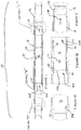
Figure 1 is a sectional view of a first embodiment of the apparatus, showing the flow control member disposed in the closed position; -
Figure 1A is a detailed view of Detail A inFigure 1 ; -
Figure 1B is a detailed view of Detail B inFigure 1 ; -
Figure 1C is a detailed view of Detail C inFigure 1 ; -
Figure 2 is a sectional view of the apparatus illustrated inFigure 1 , showing the flow control member disposed in the intermediate position; -
Figure 2A is a detailed view of Detail A inFigure 2 ; -
Figure 2B is a detailed view of Detail B inFigure 2 ; -
Figure 2C is a detailed view of Detail C inFigure 2 ; -
Figure 3 is a sectional view of the apparatus illustrated inFigure 1 , showing the flow control member disposed in the open position; -
Figure 3A is a detailed view of Detail A inFigure 3 ; -
Figure 3B is a detailed view of Detail B inFigure 3 ; -
Figure 3C is a detailed view of Detail C inFigure 3 ; -
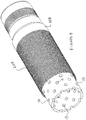
Figure 4 is a schematic illustration of a partially completed embodiment of the screened port of the apparatus illustrated inFigure 1 , showing screen having been wrapped around a portion of a perforated base pipe; and -
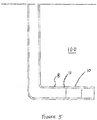
Figure 5 is a schematic illustration of the integration of the apparatus illustrated inFigure 1 within a wellbore string that is disposed within a wellbore. - There is provided an
apparatus 10 for selectively communicating with asubterranean formation 100, such as a reservoir, for effecting production of hydrocarbon material from the reservoir. The apparatus is deployable within a wellbore 8 (seeFigure 5 ). Suitable wellbores include vertical, horizontal, deviated or multi-lateral wells. Thewellbore 8 extends into asubterranean formation 100. - The
apparatus 10 is integratable within awellbore string 11 that is configured for disposition within thewellbore 8.Successive apparatuses 10 may be spaced from each other such that each apparatus is positioned adjacent a producing interval to receive production. - Referring to
Figure 1 , in some embodiments, for example, theapparatus 10 includes ahousing 12. Thehousing 12 includes aflow communicator 15. In some embodiments, for example, theflow communicator 15 is a screened flow communicator that includes one or more one or more apertures or ports 18 (seeFigure 4 ). Each one of the one ormore apertures 18 extends through thehousing 12. For each one of the one ormore apertures 18, afilter medium 20 is co-operatively disposed relative to theaperture 18 for allowing flow of fluid through the port but interfering with (for example, preventing or substantially preventing) passage of oversize solid particulate matter through theaperture 18. In some embodiments, for example, the filter medium is in the form of a screen, such as a wire screen. In some embodiments, for example, thefilter medium 20 is defined by a sand screen 20A that is wrapped around a perforated section of abase pipe 15B, the perforated section defining a plurality ofapertures 18, as illustrated inFigure 4 . In some embodiments, for example, thefilter medium 20 is in the form of a porous material that is integrated within theaperture 18. - Referring to
Figure 5 , thehousing 12 is configured for coupling (such as, for example, by threaded connection) to thewellbore string 11. The wellbore string is lining thewellbore 8. Thewellbore 11 string is provided for, amongst other things, supporting thesubterranean formation 100 within which thewellbore 8 is disposed. Thewellbore string 11 may include multiple segments, and segments may be connected (such as by a threaded connection). In some embodiments, for example, the wellbore string includes a casing string. - In some embodiments, for example, it is desirable to seal an annulus, that is formed within the wellbore, between the casing string and the subterranean formation. To prevent, or at least interfere, with conduction of the formation fluid through the annulus, and, perhaps, to a portion of the subterranean formation that is desired to be isolated from the formation fluid, or, perhaps, to the surface, the annulus is filled with a zonal isolation material. In some embodiments, for example, the zonal isolation material includes cement, and, in such cases, during installation of the assembly within the wellbore, the casing string is cemented to the
subterranean formation 100, and the resulting system is referred to as a cemented completion. - To at least mitigate ingress of cement during cementing, and also at least mitigate curing of cement in space that is in proximity to the screened
flow communicator 15, or of any cement that has become disposed within the port, prior to cementing, the port may be filled with a viscous liquid material having a viscosity of at least 100 mm2/s at 40 degrees Celsius. Suitable viscous liquid materials include encapsulated cement retardant or grease. An exemplary grease is SKF LGHP 2TM grease. For illustrative purposes below, a cement retardant is described. However, it should be understood, other types of liquid viscous materials, as defined above, could be used in substitution for cement retardants. - In some embodiments, for example, the zonal isolation material includes a packer, and, in such cases, such completion is referred to as an open-hole completion.
- A
passage 16 is defined within thehousing 12. Thepassage 16 is configured for conducting reservoir material that is received via the screened flow communicator 15 (the reservoir material includes fluid and any undersize solid particulate matter that has passed through the filter medium 20). - The
apparatus 10 also includes aflow control member 14. Theflow control member 14 is displaceable, relative to the screenedflow communicator 15, between a closed position and an open position. - Referring to
Figures 1, 1A, 1B, and 1C , when theflow control member 14 is disposed in the closed position, in some embodiments, for example, the screenedflow communicator 15 is disposed in a closed condition, and in the closed condition, there is an absence, or substantial absence of fluid communication between thepassage 16 and the subterranean formation via the screened port. In other words, fluid communication between thepassage 16 and the subterranean formation via the screenedflow communicator 15 is prevented or substantially prevented. - Referring to
Figures 3, 3A, 3B, and 3C , when theflow control member 14 is disposed in the open position, in some embodiments, for example, theflow communicator 15 is disposed in an open condition, and in the open condition, theflow communicator 15 is effecting flow communication between thepassage 16 and an environment external to thehousing 12, such as the subterranean formation. In some embodiments, for example, while theflow communicator 15 is disposed in the open condition, there is an absence of occlusion of any portion, or substantially any portion, of the port by the flow control member; In some embodiments, for example, the disposition of theflow control member 14 in the open position is such that the entirety, or substantially the entirety, of the screenedflow communicator 15 is non-occluded by theflow control member 14. - In some embodiments, for example, the
flow control member 14 and theflow communicator 15 are co-operatively configured such that, while theflow control member 14 is disposed in the closed position, the resistance to fluid flow through theflow communicator 15 is greater than the resistance to fluid through theflow communicator 15 while theflow control member 14 is disposed in the open position, by a multiple of at least two (2). In some embodiments, for example, the multiple is at least three (3), such as, for example, at least four (4), such as, for example, at least five (5). - In some embodiments, for example, the
flow control member 14 is displaceable from the closed position to the open position for effecting fluid communication between the subterranean formation and thepassage 16 such that reservoir fluids are producible via thewellbore 8. - In some embodiments, for example, the
flow control member 14 is displaceable from the open position to the closed position while fluids are being produced from the subterranean formation through theflow communicator 15, and in response to sensing of a sufficiently high rate of water production from the subterranean formation through theflow communicator 15. In such case, moving theflow control member 14 blocks further production through theflow communicator 15. - In some embodiments, for example, the
flow control member 14 is displaceable along an axis that is parallel to the central longitudinal axis of thepassage 16. - In some embodiments, for example, the
flow control member 14 includes a sleeve. The sleeve is slideably disposed within thepassage 16. - In some embodiments, for example, the
housing 12 includes sealing surfaces 11A, 11B configured for sealing engagement with theflow control member 14. In this respect, in some embodiments, for example, theflow control member 14 includes sealing members 111A, 111B. Theflow communicator 15 is disposed between the sealing surfaces 11A, 11B. In some embodiments, for example, when theflow control member 14 is disposed in a position corresponding to the closed position (such that theflow communicator 15 is disposed in the closed condition), each one of the sealing members 111A, 111B, is, independently, disposed in sealing engagement with both of thehousing 12 and theflow control member 14 such that a sealed interface is defined. In some embodiments, for example, the sealed interface is defined by a first counterpart and a second counterpart In some embodiments, for example, the first counterpart is defined by the flow control member and the second counterpart is defined by the housing. In this respect, in the illustrated embodiment, the first counterpart includes the sealing members 111A, 111B and the second counterpart includes the sealing surfaces 11A, 11B, such that the sealed interface is defined while the sealing members 111A, 111B are disposed in contact engagement with the sealing surfaces 11A, 11B. It is understood that, alternatively, the sealing members 111A, 111B could be coupled to thehousing 12 and the sealing surfaces 11A, 11B could be defined on theflow control member 14, and other combinations are also possible. While the sealed interface is defined, flow communication between thepassage 16 and the subterranean formation, via theflow communicator 15, is sealed or substantially sealed. - In some embodiments, for example, each one of the sealing members 111A, 111B, independently, includes an o-ring. In the illustrated embodiment, for example, the o-ring is housed within a recess formed within the
flow control member 14. In some embodiments, for example, each one of the sealing members 111A, 111B, independently, includes a molded sealing member (i.e. a sealing member that is fitted within, and/or bonded to, a groove formed within the sub that receives the sealing member). - In some embodiments, for example, the
flow control member 14 co-operates with the sealing surfaces 11A, 11B to effect opening and closing of theflow communicator 15. While the screenedflow communicator 15 is disposed in the closed position, theflow control member 14 is sealingly engaged to both of the sealing surfaces 11A, 11B. While theflow communicator 15 is disposed in the open condition, theflow control member 14 is spaced apart or retracted from at least one of the sealing surfaces (referring toFigure 3 , in the illustrated embodiment, this would be the sealing surface 11B), thereby providing a passage for reservoir material to be conducted to thepassage 16 via theflow communicator 15. - In some embodiments, for example, a flow control member-engaging
collet 22 extends from thehousing 12, and is configured to engage theflow control member 14 for resisting a displacement of the flow control member. In some embodiments, for example, the flow control member-engagingcollet 22 includes at least one resilient flow control member-engaging collet finger 22A, and each one of the at least one flow control member-engaging collet finger includes atab 22B that engages the flow control member. - In some embodiments, for example, the
flow control member 14 and the flow control member-engagingcollet 22 are co-operatively configured such that engagement of theflow control member 14 by the flow control member-engagingcollet 22 is effected while the screenedflow communicator 15 is disposed in the closed condition. - Referring to
Figure 1, 1A, 1B, and 1C , while theflow control member 14 is disposed in the closed position (i.e. theflow communicator 15 is disposed in the closed condition) the flow control member-engagingcollet 22 is engaging theflow control member 14 such that interference or resistance is being effected to displacement of theflow control member 14. Theflow control member 14 includes a closed condition-definingrecess 24. The at least one flow control member-engaging collet finger 22A and therecess 24 are co-operatively configured such that, while the flow control member-engagingcollet finger tab 22B is disposed within the closed condition-definingrecess 24, theflow control member 14 is disposed in the closed position. In order to effect a displacement of theflow control member 14 while the flow control member-engagingcollet finger tab 22B is disposed within the closed condition-definingrecess 24, a first displacement force is applied to theflow control member 14 to effect displacement of thetab 22B from (or out of) therecess 24. Such displacement is enabled due to the resiliency of the collet finger 22A. Once the flow control member-engagingcollet finger tab 22B has become displaced out of therecess 24, continued application of force to the flow control member 14 (such as, in the embodiments illustrated inFigures 1 , in a downhole direction) effects displacement of theflow control member 14, relative to theflow communicator 15. - Referring to
Figures 3, 3A, 3B, and 3C , while theflow control member 14 is disposed in the open position (i.e. theflow communicator 15 is disposed in the open condition), the flow control member-engagingcollet 22 is engaging theflow control member 14 such that interference or resistance is being effected to displacement of theflow control member 14. Theflow control member 14 includes an open condition-definingrecess 26. The at least one flow control member-engaging collet finger 22A and therecess 26 are co-operatively configured such that, while the flow control member-engagingcollet finger tab 22B is disposed within the open condition-definingrecess 26, the screenedflow communicator 15 is disposed in the open condition. In order to effect a displacement of theflow control member 14, while the flow control member-engagingcollet finger tab 22B is disposed within the open condition-definingrecess 26, a second displacement force is applied to theflow control member 14 to effect displacement of the tab from (or out of) therecess 26. Such displacement is enabled due to the resiliency of the collet finger 22A. Once the flow control member-engagingcollet finger tab 22B has become displaced out of therecess 26, continued application of the second displacement force to the flow control member 14 (such as, in the embodiment illustrated inFigure 2 , in a downhole direction) effects displacement of theflow control member 14, relative to the screenedflow communicator 15. - In some embodiments, for example, the displacement forces are applied to the
flow control member 14 mechanically, hydraulically, or a combination thereof. In some embodiments, for example, the applied forces are mechanical forces, and such forces are applied by one or more shifting tools. In some embodiments, for example, the applied forces are hydraulic, and are applied by a pressurized fluid. In those embodiments where the mechanical forces are applied by a shifting tool, in some of these embodiments, for example, thepassage 16 is configured to receive the shifting tool for applying mechanical forces to theflow control member 14 to effect the displacement of theflow control member 14. - Referring to
Figure 1 , in some embodiments, for example, while theapparatus 10 is being deployed downhole, theflow control member 14 is maintained in the closed position, by one or more frangible interlocking members 30 (such as, for example, shear pins), such that theflow communicator 15 remains disposed in the closed condition. The one or more frangible interlockingmembers 30 are provided to releasably retain theflow control member 14 to thehousing 12 so that thepassage 16 is maintained fluidically isolated from the subterranean formation until it is desired to effect hydrocarbon production from the subterranean formation. In some embodiments, for example, the one or more frangible interlockingmembers 30 extends throughapertures 14B provided in acentralizer portion 14A of theflow control member 14. - While the
flow control member 14 is releasably retained to the housing by the one or more frangible interlockingmembers 30, theflow control member 14 is disposed in a retained position. To effect the fracturing (such as, for example, fracturing) of frangible interlockingmembers 30 such that theflow control member 14 is displaceable relative to theflow communicator 15, sufficient force must be applied to theflow control member 14 such that the one or more frangible interlockingmembers 30 become fractured, resulting in theflow control member 14 becoming displaceable relative to the screenedflow communicator 15. In some operational implementations, the force that effects the fracturing are applied to theflow control member 14 mechanically, hydraulically, or a combination thereof. In the embodiment illustrated inFigure 1 , for example, the force that effects the fracturing is applied in a downhole direction. - In some embodiments, for example, while the flow control member is retained to the
housing 12 by the one or more frangible interlockingmembers 30, theflow control member 14 is positioned in the closed position (such that theflow communicator 15 is disposed in the closed condition). In some embodiments, for example, while theflow control member 14 is retained to thehousing 12 by the one or more frangible interlockingmembers 30, theflow control member 14 is positioned downhole relative to the space occupied by theflow control member 14 while disposed in the open position (i.e. while the flow communicator is disposed in the open condition). In this respect, theflow control member 14 is disposed uphole relative to the retained position while theflow communicator 15 is disposed in the open condition - In such embodiments, for example, the one or more frangible interlocking
members 30 are configured for fracturing (such that theflow control member 14 is displaceable relative to the screened flow communicator 15) by application of a sufficient downhole force. Upon the fracturing of the one or more frangible interlockingmembers 30, theflow control member 14 becomes released from the retention relative to thehousing 12, and continued application of the downhole force effects displacement of theflow control member 14 in a downhole direction. If the downhole force were permitted to continue to effect the displacement of theflow control member 14 in a downhole direction, theflow control member 14 would continue to accelerate, and attain a sufficiently high speed, such that, upon rapid deceleration of theflow control member 14 caused by an obstruction to its downhole displacement (such as by a hard stop), associated components become vulnerable to damage. In this respect, the displacement of theflow control member 14 in a downhole direction, that is effected after the fracturing of the one or more frangible interlockingmembers 30, is limited by ahard stop 32 that extends from thehousing 12 and into thepassage 16. While theflow control member 14 is disposed in contact engagement (such as, for example, in an abutting relationship) with thehard stop 32, the flow control member is disposed in a downhole displacement prevention position. The distance that theflow control member 14 is permitted to travel (by virtue of the hard stop 32), after having become released from thehousing 12 upon the fracturing of the frangible interlocking members, is sufficiently short such that the speed attained by theflow control member 14 is sufficiently slow such that there is an absence of mechanical damage to associated components upon engagement of thehard stop 32 by the flow control member 14 (seeFigures 2, 2A, 2B, and 2C ). - Relatedly, in those embodiments where the
flow communicator 15 has a dimension, measured along an axis that is parallel to the central longitudinal axis of thepassage 16, that is greater than the distance between the retained position and the downhole displacement prevention position, as measured along the central longitudinal axis of the passage, then theflow communicator 15 is positioned uphole relative to the space occupied by theflow control member 14, while theflow control member 14 is retained to thehousing 12 by the one or more frangible interlockingmembers 30, such that opening of the screenedflow communicator 15 is effectible, after theflow control member 14 has become engaged to thehard stop 32, by sufficient uphole displacement of theflow control member 14 relative to, and beyond, theflow communicator 15. Otherwise, if theflow communicator 15 were to be located downhole relative to the space occupied by theflow control member 14, while theflow control member 14 is retained to thehousing 12 by the one or more frangible interlockingmembers 30, and, in complementary fashion, thehard stop 32 were to be positioned further downhole so as to permit sufficient downhole displacement of theflow control member 14 to effect the opening of theflow communicator 15, then the speed attainable by theflow control member 14, while the downhole force continues to be applied after the fracturing of the one or more frangible interlockingmembers 30, is sufficiently high such that associated components are vulnerable to damage upon theflow control member 14 becoming disposed in contact engagement with thehard stop 32. Similar concerns about component damage are not present while displacing theflow control member 14 in an uphole direction, after the one or more frangible interlockingmembers 30 having become fractured, as it is easier to maintain a lower applied force to effect such uphole displacement, relative to theflow communicator 15, in these circumstances, relative to the above-described circumstances where the displacement of theflow control member 14, to effect opening of theflow communicator 15, is effected by a downhole force that continues to be applied after having effected the fracturing of the one or more frangible interlockingmembers 30. - In this respect, In some embodiments, for example, a dimension of the
flow communicator 15, measured along an axis that is parallel to the central longitudinal axis of thepassage 16, is at least one (1) foot (approximately 30cm), such as at least (approximately 91cm), such as at least five (5) feet (approximately 152cm), or such as, for example, at least eight (8) feet (approximately 244cm). In some embodiments, for example, a dimension of the screenedflow communicator 15, measured along an axis that is parallel to the central longitudinal axis of thepassage 16, is ten (10) feet (approximately 305cm). In some embodiments, for example, the flow communicator 1115 defines an available flow area, through which the flow communication is effectible, of at least 80 square inches (approximately 516cm2), such as, for example, at least 120 square inches (approximately 774cm2), such as, for example, at least 160 square inches (approximately 1032cm2), such as, for example, at least 200 square inches (approximately 1290cm2). Relatedly, in some embodiments, for example, the distance between the retained position and the downhole displacement prevention position, as measured along the central longitudinal axis of thepassage 16, is less than six (6) inches (approximately 15cm), such as less than three (3) inches (approximately 8cm), or such as less than two (2) inches (approximately 5cm). - In some embodiments, for example, it is desirable to mitigate damage to sealing members, associated with the formation of the above-described sealed interface, by portions of the
frangible interlocking members 30 that are produced by the fracturing. In this respect, in some embodiments, for example, while theflow control member 14 is being retained to the housing by the one or more frangible interlockingmembers 30, the one or more frangible interlocking members are disposed uphole relative to theflow communicator 15. Also in this respect, in some embodiments, for example, while theflow control member 14 is being retained to the housing by the one or more frangible interlockingmembers 30, the one or more frangible interlocking members are disposed uphole relative to the sealing members 111A, 111B that are effecting the sealed interface, and, in this respect, uphole of the sealing members 111A, 111B of the sealing member-embodying counterpart (defined, in the illustrated embodiment, by the flow control member 14) of the counterparts (the first and second counterparts, as above-described) that are configured to define the sealed interface. In such a configuration, after the fracturing of the one or morefrangible members 30 by application of a downhole force that effects downhole displacement of theflow control member 14 relative to the flow communicator, because the one or more frangible interlocking members are originally disposed uphole relative to the sealing members 111A, 111B, broken pieces of the one or more frangible interlockingmembers 30 are less likely to come into contact with the sealing members 111A, 111B, during the subsequent uphole displacement of theflow control member 14 for effecting opening of theflow communicator 15, and thereby damage the sealing members 111A, 111B. - In some embodiments, for example, while the
flow control member 14 is disposed in the downhole displacement prevention position, theflow communicator 15 is disposed in the closed condition. In this respect, in some embodiments, it is desirable to release theflow control members 14 of all of theapparatuses 10 within thewellbore string 11 in a single trip in a downhole direction (and then subsequently open theflow communicators 15 of theapparatuses 10 in a single trip uphole), and it is desirable that theflow communicators 15 remain closed while the "releasing" operation is being carried out. In this respect, in some embodiments, for example, theflow communicator 15 is disposed in the closed condition while the flow control member is disposed in the downhole displacement prevention position. - Referring to
Figures 3, 3A, 3B, and 3C , in some embodiments, for example, theapparatus 10 includes ahard stop 34 for limiting displacement of theflow control member 14, in an uphole direction, relative to theflow communicator 15. In this respect, in some embodiments, for example, while engaged to thehard stop 34, theflow control member 14 is disposed in the open position, such that theflow communicator 15 is disposed in the open condition, and thehard stop 34 determines the open position of theflow control member 14. In this respect, after theflow control member 14 is released from the retention relative to thehousing 12 and becomes disposed in the downhole displacement prevention position, opening of theflow communicator 15 is effectible by displacement of theflow control member 14, relative to theflow communicator 15, in an uphole direction in response to an uphole pulling force (such as one imparted by a shifting tool). - In some embodiments, for example, all of the displacement forces are imparted by a shifting tool, and the shifting tool is integrated within a bottom hole assembly that includes other functionalities. The bottomhole assembly may be deployed within the wellbore on a workstring. Suitable workstrings include tubing string, wireline, cable, or other suitable suspension or carriage systems. Suitable tubing strings include jointed pipe, concentric tubing, or coiled tubing. The workstring includes a passage, extending from the surface, and disposed in, or disposable to assume, fluid communication with the fluid conducting structure of the tool. The workstring is coupled to the bottomhole assembly such that forces applied to the workstring are translated to the bottomhole assembly to actuate movement of the
flow control member 14.
Claims (13)
- An apparatus for deployment in a wellbore to control flow of formation fluids into the wellbore from a subterranean reservoir, comprising:a housing (12);a hard stop (32);a housing passage (16) disposed within the housing;a flow communicator (15) for effecting, while disposed in an open condition, flow communication between the housing passage and an environment external to the housing;a flow control member (14); andone or more frangible interlocking members (30) releasably retaining the flow control member to the housing such that the flow control member is disposed in a retained position, and configured, while the apparatus is disposed in an operative orientation within the wellbore (8), for becoming fractured in response to application of a sufficient force in a downhole direction such that release of the flow control member from the retention relative to the housing is effected such that the flow control member becomes displaceable relative to the flow communicator;wherein:the flow communicator and the flow control member are co-operatively configured such that, while the apparatus is disposed in the operative orientation within the wellbore, the flow control member is disposed uphole relative to the retained position while the flow communicator is disposed in the open condition;the hard stop and the flow control member are co-operatively configured such that, while the apparatus is disposed in the operative orientation within the wellbore, the hard stop is disposed downhole relative to the retained flow control member for preventing, or substantially preventing, downhole displacement of the flow control member relative to the flow communicator after the flow control member has been released from the retention relative to the housing;while the apparatus is disposed in the operative orientation within the wellbore and the flow control member is disposed in contact engagement with the hard stop, the flow control member is disposed in a downhole displacement prevention position and is prevented, or substantially prevented, from displacement downhole relative to the flow communicator;the flow communicator has a dimension, measured along an axis that is parallel to the central longitudinal axis of the housing passage, that is greater than the distance between the retained position and the downhole displacement prevention position, as measured along the central longitudinal axis of the housing passage;the distance between the retained position and the downhole displacement prevention position, as measured along the central longitudinal axis of the housing passage, is less than six inches (15,24cm); andthe opening of the flow communicator is effectible by displacement of the flow control member, relative to the flow communicator, to an open position, after releasing of the flow control member from the retention relative to the housing;while the flow control member is disposed in the open position, the entirety, or substantially the entirety, of the flow communicator is non-occluded by the flow control member; andthe distance between the retained position and the open position, as measured along the central longitudinal axis of the housing passage, is at least one foot (30,48cm).
- The apparatus as claimed in claim 1;
wherein the dimension of the flow communicator (15), as measured along an axis that is parallel to the central longitudinal axis of the housing passage (16), is at least one foot (30,48cm). - The apparatus as claimed in any one of claims 1 or 2;
wherein:
the flow control member (14), the hard stop (32), and the flow communicator (15) are co-operatively configured such that, while the apparatus is disposed in the operative orientation within the wellbore (8) and the flow control member is disposed in contact engagement with the hard stop such that the downhole displacement of the flow control member relative to the flow communicator is prevented or substantially prevented, the flow communicator is disposed in a closed condition such that flow communication between the housing passage (16) and the environment external to the housing, via the flow communicator, is prevented or substantially prevented. - The apparatus as claimed in any one of claims 1 to 3;
wherein the one or more frangible members (30) and the flow communicator (15) are co-operatively configured such that, while the apparatus is disposed in the operative orientation within the wellbore (8), the one or more frangible members are disposed uphole relative to the flow communicator. - The apparatus as claimed in claim 4;
wherein:the flow control member (14) and the housing (12) are co-operatively configured such that, while the flow control member is disposed in the closed position, a sealed interface is defined such that the flow communication between the housing passage (16) and the environment external to the housing, via the flow communicator (15), is sealed or substantially sealed;the sealed interface is defined by a first counterpart, defined by the flow control member, and a second counterpart, defined by the housing, and at least one of the first and second counterparts is a sealing member-embodying counterpart that includes one or more sealing members for effecting the sealed interface, such that at least one sealing member-embodying counterpart is provided; andthe one or more frangible members (30) and the at least one sealing member-embodying counterpart are co-operatively configured such that, while the apparatus is disposed in the operative orientation within the wellbore (8) and the one or more frangible members are releasably retaining the flow control member, for each one of the at least one sealing member-embodying counterpart, the one or more frangible members are disposed uphole relative to the one or more sealing members of the sealing member-embodying counterpart. - The apparatus as claimed in any one of claims 1 to 5;
wherein the flow communicator (15) defines an available flow area, through which the flow communication is effectible, of at least 80 square inches (516,128cm2), - The apparatus as claimed in any one of claims 1 to 6;
wherein:
the flow communicator (15) is a screened flow communicator. - The apparatus as claimed in claim 7;
wherein:the screened flow communicator includes one or more apertures extending through the housing; andfor each one of the one or more aperture, a filter medium is co-operatively disposed relative to the aperture for allowing flow of fluid through the aperture but interfering with passage of oversize particulate material through the aperture. - A method of producing hydrocarbon-comprising material from a subterranean formation via a wellbore extending into the subterranean formation, comprising:applying a downhole force to a flow control member (14) that is releasably retained to a housing, in a retained position, with one or more frangible interlocking members (30), such that: (i) fracturing of the one or more frangible interlocking members is effected such that the flow control member is released from the retention relative to the housing (12), and (ii) the flow control member is displaced downhole until the flow control member becomes disposed in contact engagement with a hard stop (32) such that further downhole displacement is prevented or substantially prevented; andafter the flow control member has become disposed in contact engagement with the hard stop, displacing the flow control member in an uphole direction such that opening of a flow communicator is effected for effecting flow communication between the wellbore (8) and the subterranean formation;wherein:the displacement of the flow control member is through a housing passage (16);while the flow control member is disposed in contact engagement with the hard stop, the flow control member is disposed in a downhole displacement prevention position; andthe flow communicator (15) has a dimension, measured along an axis that is parallel to the central longitudinal axis of the housing passage, that is greater than the distance between the retained position and the downhole displacement prevention position, as measured along the central longitudinal axis of the housing passage;the distance between the retained position and the downhole displacement prevention position, as measured along the central longitudinal axis of the housing passage, is less than six inches (15,24cm)the opening of the flow communicator is effected by displacement of the flow control member to an open position, after release from the retention relative to the housing;while the flow control member is disposed in the open position, there is an absence of occlusion of any portion, or substantially any portion, of the flow communicator is non-occluded by the flow control member; andthe distance between the retained position and the open position, as measured along the central longitudinal axis of the housing passage, is at least one foot (30,48cm).
- The method as claimed in claim 9;
wherein the dimension of the flow communicator (15), as measured along an axis that is parallel to the central longitudinal axis of the housing passage (16), is at least one foot (30,48cm). - The method as claimed in claim 9 or 10;
wherein:
while the flow control member (14) is disposed in contact engagement with the hard stop (32) such that the downhole displacement of the flow control member relative to the flow communicator (15) is prevented or substantially prevented, the flow communicator is disposed in the closed condition such that flow communication between the housing passage (16) and the environment external to the housing, via the flow communicator, is prevented or substantially prevented. - The method as claimed in any one of claims 9 to 11;
wherein:
the flow communicator (15) is a screened flow communicator. - The apparatus as claimed in claim 12;
wherein:the screened flow communicator includes one or more apertures extending through the housing; andfor each one of the one or more aperture, a filter medium is co-operatively disposed relative to the aperture for allowing flow of fluid through the aperture but interfering with passage of oversize particulate material through the aperture.
Applications Claiming Priority (2)
| Application Number | Priority Date | Filing Date | Title |
|---|---|---|---|
| US201662395776P | 2016-09-16 | 2016-09-16 | |
| PCT/CA2017/051093 WO2018049533A1 (en) | 2016-09-16 | 2017-09-15 | Wellbore flow control apparatus with solids control |
Publications (3)
| Publication Number | Publication Date |
|---|---|
| EP3513031A1 EP3513031A1 (en) | 2019-07-24 |
| EP3513031A4 EP3513031A4 (en) | 2020-04-29 |
| EP3513031B1 true EP3513031B1 (en) | 2021-06-16 |
Family
ID=61619845
Family Applications (1)
| Application Number | Title | Priority Date | Filing Date |
|---|---|---|---|
| EP17849974.5A Active EP3513031B1 (en) | 2016-09-16 | 2017-09-15 | Wellbore flow control apparatus with solids control |
Country Status (5)
| Country | Link |
|---|---|
| US (1) | US11078753B2 (en) |
| EP (1) | EP3513031B1 (en) |
| CA (1) | CA3037162C (en) |
| DK (1) | DK3513031T3 (en) |
| WO (1) | WO2018049533A1 (en) |
Families Citing this family (2)
| Publication number | Priority date | Publication date | Assignee | Title |
|---|---|---|---|---|
| CA3037162C (en) | 2016-09-16 | 2024-04-09 | Ncs Multistage Inc. | Wellbore flow control apparatus with solids control |
| US11578562B2 (en) * | 2020-11-27 | 2023-02-14 | Ncs Multistage Inc. | Systems and methods for producing hydrocarbon material from or injecting fluid into a subterranean formation using adjustable flow restriction |
Family Cites Families (32)
| Publication number | Priority date | Publication date | Assignee | Title |
|---|---|---|---|---|
| US3695355A (en) | 1970-01-16 | 1972-10-03 | Exxon Production Research Co | Gravel pack method |
| AU638282B2 (en) | 1989-11-08 | 1993-06-24 | Halliburton Company | Casing valve |
| US5479989A (en) | 1994-07-12 | 1996-01-02 | Halliburton Company | Sleeve valve flow control device with locator shifter |
| GB9715001D0 (en) | 1997-07-17 | 1997-09-24 | Specialised Petroleum Serv Ltd | A downhole tool |
| US6892816B2 (en) | 1998-11-17 | 2005-05-17 | Schlumberger Technology Corporation | Method and apparatus for selective injection or flow control with through-tubing operation capacity |
| US6276458B1 (en) | 1999-02-01 | 2001-08-21 | Schlumberger Technology Corporation | Apparatus and method for controlling fluid flow |
| GB2399847A (en) * | 2000-08-17 | 2004-09-29 | Abb Offshore Systems Ltd | Flow control device |
| WO2003023185A1 (en) | 2001-09-07 | 2003-03-20 | Shell Internationale Research Maatschappij B.V. | Adjustable well screen assembly |
| CA2412072C (en) | 2001-11-19 | 2012-06-19 | Packers Plus Energy Services Inc. | Method and apparatus for wellbore fluid treatment |
| US6899176B2 (en) | 2002-01-25 | 2005-05-31 | Halliburton Energy Services, Inc. | Sand control screen assembly and treatment method using the same |
| US7255173B2 (en) | 2002-11-05 | 2007-08-14 | Weatherford/Lamb, Inc. | Instrumentation for a downhole deployment valve |
| US7387165B2 (en) | 2004-12-14 | 2008-06-17 | Schlumberger Technology Corporation | System for completing multiple well intervals |
| US7793716B2 (en) | 2006-04-21 | 2010-09-14 | Bj Services Company, U.S.A. | Apparatus and methods for limiting debris flow back into an underground base pipe of an injection well |
| US7921915B2 (en) | 2007-06-05 | 2011-04-12 | Baker Hughes Incorporated | Removable injection or production flow equalization valve |
| US7971646B2 (en) | 2007-08-16 | 2011-07-05 | Baker Hughes Incorporated | Multi-position valve for fracturing and sand control and associated completion methods |
| US7703510B2 (en) | 2007-08-27 | 2010-04-27 | Baker Hughes Incorporated | Interventionless multi-position frac tool |
| US8127847B2 (en) | 2007-12-03 | 2012-03-06 | Baker Hughes Incorporated | Multi-position valves for fracturing and sand control and associated completion methods |
| US8757273B2 (en) | 2008-04-29 | 2014-06-24 | Packers Plus Energy Services Inc. | Downhole sub with hydraulically actuable sleeve valve |
| CA2719561A1 (en) * | 2008-04-29 | 2009-11-05 | Packers Plus Energy Services Inc. | Downhole sub with hydraulically actuable sleeve valve |
| US8297358B2 (en) | 2010-07-16 | 2012-10-30 | Baker Hughes Incorporated | Auto-production frac tool |
| CA2810412C (en) | 2010-09-22 | 2018-11-27 | Packers Plus Energy Services Inc. | Wellbore frac tool with inflow control |
| US20120186803A1 (en) | 2011-01-21 | 2012-07-26 | Baker Hughes Incorporated | Combined Fracturing Outlet and Production Port for a Tubular String |
| EP2723972A1 (en) | 2011-06-21 | 2014-04-30 | Packers Plus Energy Services Inc. | Fracturing port locator and isolation tool |
| US9200502B2 (en) | 2011-06-22 | 2015-12-01 | Schlumberger Technology Corporation | Well-based fluid communication control assembly |
| AU2012308069A1 (en) | 2011-09-12 | 2014-03-27 | Packers Plus Energy Services Inc. | Wellbore frac tool with inflow control |
| WO2013075235A1 (en) | 2011-11-21 | 2013-05-30 | Packers Plus Energy Services Inc. | Inflow control solutions for wellbores |
| US9341046B2 (en) | 2012-06-04 | 2016-05-17 | Schlumberger Technology Corporation | Apparatus configuration downhole |
| US9784070B2 (en) | 2012-06-29 | 2017-10-10 | Halliburton Energy Services, Inc. | System and method for servicing a wellbore |
| US9574422B2 (en) | 2012-07-13 | 2017-02-21 | Baker Hughes Incorporated | Formation treatment system |
| CA3034357C (en) * | 2014-08-19 | 2019-10-29 | Ncs Multistage Inc. | Apparatus, system and method for treating a reservoir using re-closeable sleeves |
| US10180046B2 (en) * | 2014-12-23 | 2019-01-15 | Ncs Multistage Inc. | Downhole flow control apparatus with screen |
| CA3037162C (en) | 2016-09-16 | 2024-04-09 | Ncs Multistage Inc. | Wellbore flow control apparatus with solids control |
-
2017
- 2017-09-15 CA CA3037162A patent/CA3037162C/en active Active
- 2017-09-15 DK DK17849974.5T patent/DK3513031T3/en active
- 2017-09-15 US US16/333,845 patent/US11078753B2/en active Active
- 2017-09-15 WO PCT/CA2017/051093 patent/WO2018049533A1/en not_active Ceased
- 2017-09-15 EP EP17849974.5A patent/EP3513031B1/en active Active
Also Published As
| Publication number | Publication date |
|---|---|
| EP3513031A4 (en) | 2020-04-29 |
| CA3037162C (en) | 2024-04-09 |
| DK3513031T3 (en) | 2021-08-02 |
| US11078753B2 (en) | 2021-08-03 |
| WO2018049533A1 (en) | 2018-03-22 |
| US20190264533A1 (en) | 2019-08-29 |
| CA3037162A1 (en) | 2018-03-22 |
| EP3513031A1 (en) | 2019-07-24 |
Similar Documents
| Publication | Publication Date | Title |
|---|---|---|
| CA2916168C (en) | Downhole flow control apparatus with screen | |
| US10472928B2 (en) | Downhole sleeve assembly and sleeve actuator therefor | |
| US10683730B2 (en) | Apparatus and method for treating a reservoir using re-closeable sleeves, and actuating the sleeves with bi-directional slips | |
| US20030024706A1 (en) | Downhole surge reduction method and apparatus | |
| CA2859813C (en) | Apparatus, system and method for treating a reservoir using re-closeable sleeves | |
| US10161207B2 (en) | Apparatus, system and method for treating a reservoir using re-closeable sleeves and novel use of a shifting tool | |
| US20150376985A1 (en) | Autofill and circulation assembly and method of using the same | |
| US20190153825A1 (en) | Liner Conveyed Compliant Screen System | |
| US20140182849A1 (en) | Wellbore Servicing Assemblies and Methods of Using the Same | |
| CA3037162C (en) | Wellbore flow control apparatus with solids control | |
| US20220003094A1 (en) | Process for producing hydrocarbon material from a subterranean formation while employing solids control | |
| CA2963386C (en) | Well tool with indexing device | |
| US9091134B2 (en) | Expendable mechanical release packer plug for heavy mud | |
| CA3132283C (en) | Multiple port opening method with single pressure activation | |
| WO2016090110A1 (en) | Cable protector gauge carrier for reading reservoir pressure through cement |
Legal Events
| Date | Code | Title | Description |
|---|---|---|---|
| STAA | Information on the status of an ep patent application or granted ep patent |
Free format text: STATUS: THE INTERNATIONAL PUBLICATION HAS BEEN MADE |
|
| PUAI | Public reference made under article 153(3) epc to a published international application that has entered the european phase |
Free format text: ORIGINAL CODE: 0009012 |
|
| STAA | Information on the status of an ep patent application or granted ep patent |
Free format text: STATUS: REQUEST FOR EXAMINATION WAS MADE |
|
| 17P | Request for examination filed |
Effective date: 20190319 |
|
| AK | Designated contracting states |
Kind code of ref document: A1 Designated state(s): AL AT BE BG CH CY CZ DE DK EE ES FI FR GB GR HR HU IE IS IT LI LT LU LV MC MK MT NL NO PL PT RO RS SE SI SK SM TR |
|
| AX | Request for extension of the european patent |
Extension state: BA ME |
|
| DAV | Request for validation of the european patent (deleted) | ||
| A4 | Supplementary search report drawn up and despatched |
Effective date: 20200327 |
|
| RIC1 | Information provided on ipc code assigned before grant |
Ipc: E21B 34/10 20060101AFI20200324BHEP Ipc: E21B 34/06 20060101ALI20200324BHEP Ipc: E21B 43/12 20060101ALI20200324BHEP |
|
| GRAP | Despatch of communication of intention to grant a patent |
Free format text: ORIGINAL CODE: EPIDOSNIGR1 |
|
| STAA | Information on the status of an ep patent application or granted ep patent |
Free format text: STATUS: GRANT OF PATENT IS INTENDED |
|
| INTG | Intention to grant announced |
Effective date: 20210322 |
|
| GRAS | Grant fee paid |
Free format text: ORIGINAL CODE: EPIDOSNIGR3 |
|
| GRAA | (expected) grant |
Free format text: ORIGINAL CODE: 0009210 |
|
| STAA | Information on the status of an ep patent application or granted ep patent |
Free format text: STATUS: THE PATENT HAS BEEN GRANTED |
|
| AK | Designated contracting states |
Kind code of ref document: B1 Designated state(s): AL AT BE BG CH CY CZ DE DK EE ES FI FR GB GR HR HU IE IS IT LI LT LU LV MC MK MT NL NO PL PT RO RS SE SI SK SM TR |
|
| REG | Reference to a national code |
Ref country code: GB Ref legal event code: FG4D |
|
| REG | Reference to a national code |
Ref country code: CH Ref legal event code: EP |
|
| REG | Reference to a national code |
Ref country code: DE Ref legal event code: R096 Ref document number: 602017040536 Country of ref document: DE |
|
| REG | Reference to a national code |
Ref country code: AT Ref legal event code: REF Ref document number: 1402474 Country of ref document: AT Kind code of ref document: T Effective date: 20210715 |
|
| REG | Reference to a national code |
Ref country code: IE Ref legal event code: FG4D Ref country code: NL Ref legal event code: FP |
|
| REG | Reference to a national code |
Ref country code: DK Ref legal event code: T3 Effective date: 20210726 |
|
| REG | Reference to a national code |
Ref country code: NO Ref legal event code: T2 Effective date: 20210616 |
|
| REG | Reference to a national code |
Ref country code: LT Ref legal event code: MG9D |
|
| PG25 | Lapsed in a contracting state [announced via postgrant information from national office to epo] |
Ref country code: LT Free format text: LAPSE BECAUSE OF FAILURE TO SUBMIT A TRANSLATION OF THE DESCRIPTION OR TO PAY THE FEE WITHIN THE PRESCRIBED TIME-LIMIT Effective date: 20210616 Ref country code: FI Free format text: LAPSE BECAUSE OF FAILURE TO SUBMIT A TRANSLATION OF THE DESCRIPTION OR TO PAY THE FEE WITHIN THE PRESCRIBED TIME-LIMIT Effective date: 20210616 Ref country code: BG Free format text: LAPSE BECAUSE OF FAILURE TO SUBMIT A TRANSLATION OF THE DESCRIPTION OR TO PAY THE FEE WITHIN THE PRESCRIBED TIME-LIMIT Effective date: 20210916 Ref country code: HR Free format text: LAPSE BECAUSE OF FAILURE TO SUBMIT A TRANSLATION OF THE DESCRIPTION OR TO PAY THE FEE WITHIN THE PRESCRIBED TIME-LIMIT Effective date: 20210616 |
|
| REG | Reference to a national code |
Ref country code: AT Ref legal event code: MK05 Ref document number: 1402474 Country of ref document: AT Kind code of ref document: T Effective date: 20210616 |
|
| PG25 | Lapsed in a contracting state [announced via postgrant information from national office to epo] |
Ref country code: LV Free format text: LAPSE BECAUSE OF FAILURE TO SUBMIT A TRANSLATION OF THE DESCRIPTION OR TO PAY THE FEE WITHIN THE PRESCRIBED TIME-LIMIT Effective date: 20210616 Ref country code: SE Free format text: LAPSE BECAUSE OF FAILURE TO SUBMIT A TRANSLATION OF THE DESCRIPTION OR TO PAY THE FEE WITHIN THE PRESCRIBED TIME-LIMIT Effective date: 20210616 Ref country code: RS Free format text: LAPSE BECAUSE OF FAILURE TO SUBMIT A TRANSLATION OF THE DESCRIPTION OR TO PAY THE FEE WITHIN THE PRESCRIBED TIME-LIMIT Effective date: 20210616 Ref country code: GR Free format text: LAPSE BECAUSE OF FAILURE TO SUBMIT A TRANSLATION OF THE DESCRIPTION OR TO PAY THE FEE WITHIN THE PRESCRIBED TIME-LIMIT Effective date: 20210917 |
|
| PG25 | Lapsed in a contracting state [announced via postgrant information from national office to epo] |
Ref country code: EE Free format text: LAPSE BECAUSE OF FAILURE TO SUBMIT A TRANSLATION OF THE DESCRIPTION OR TO PAY THE FEE WITHIN THE PRESCRIBED TIME-LIMIT Effective date: 20210616 Ref country code: ES Free format text: LAPSE BECAUSE OF FAILURE TO SUBMIT A TRANSLATION OF THE DESCRIPTION OR TO PAY THE FEE WITHIN THE PRESCRIBED TIME-LIMIT Effective date: 20210616 Ref country code: SM Free format text: LAPSE BECAUSE OF FAILURE TO SUBMIT A TRANSLATION OF THE DESCRIPTION OR TO PAY THE FEE WITHIN THE PRESCRIBED TIME-LIMIT Effective date: 20210616 Ref country code: SK Free format text: LAPSE BECAUSE OF FAILURE TO SUBMIT A TRANSLATION OF THE DESCRIPTION OR TO PAY THE FEE WITHIN THE PRESCRIBED TIME-LIMIT Effective date: 20210616 Ref country code: AT Free format text: LAPSE BECAUSE OF FAILURE TO SUBMIT A TRANSLATION OF THE DESCRIPTION OR TO PAY THE FEE WITHIN THE PRESCRIBED TIME-LIMIT Effective date: 20210616 Ref country code: CZ Free format text: LAPSE BECAUSE OF FAILURE TO SUBMIT A TRANSLATION OF THE DESCRIPTION OR TO PAY THE FEE WITHIN THE PRESCRIBED TIME-LIMIT Effective date: 20210616 Ref country code: RO Free format text: LAPSE BECAUSE OF FAILURE TO SUBMIT A TRANSLATION OF THE DESCRIPTION OR TO PAY THE FEE WITHIN THE PRESCRIBED TIME-LIMIT Effective date: 20210616 Ref country code: PT Free format text: LAPSE BECAUSE OF FAILURE TO SUBMIT A TRANSLATION OF THE DESCRIPTION OR TO PAY THE FEE WITHIN THE PRESCRIBED TIME-LIMIT Effective date: 20211018 |
|
| PG25 | Lapsed in a contracting state [announced via postgrant information from national office to epo] |
Ref country code: PL Free format text: LAPSE BECAUSE OF FAILURE TO SUBMIT A TRANSLATION OF THE DESCRIPTION OR TO PAY THE FEE WITHIN THE PRESCRIBED TIME-LIMIT Effective date: 20210616 |
|
| REG | Reference to a national code |
Ref country code: DE Ref legal event code: R097 Ref document number: 602017040536 Country of ref document: DE |
|
| REG | Reference to a national code |
Ref country code: DE Ref legal event code: R119 Ref document number: 602017040536 Country of ref document: DE |
|
| PLBE | No opposition filed within time limit |
Free format text: ORIGINAL CODE: 0009261 |
|
| STAA | Information on the status of an ep patent application or granted ep patent |
Free format text: STATUS: NO OPPOSITION FILED WITHIN TIME LIMIT |
|
| REG | Reference to a national code |
Ref country code: CH Ref legal event code: PL |
|
| REG | Reference to a national code |
Ref country code: BE Ref legal event code: MM Effective date: 20210930 |
|
| 26N | No opposition filed |
Effective date: 20220317 |
|
| PG25 | Lapsed in a contracting state [announced via postgrant information from national office to epo] |
Ref country code: MC Free format text: LAPSE BECAUSE OF FAILURE TO SUBMIT A TRANSLATION OF THE DESCRIPTION OR TO PAY THE FEE WITHIN THE PRESCRIBED TIME-LIMIT Effective date: 20210616 Ref country code: AL Free format text: LAPSE BECAUSE OF FAILURE TO SUBMIT A TRANSLATION OF THE DESCRIPTION OR TO PAY THE FEE WITHIN THE PRESCRIBED TIME-LIMIT Effective date: 20210616 |
|
| PG25 | Lapsed in a contracting state [announced via postgrant information from national office to epo] |
Ref country code: LU Free format text: LAPSE BECAUSE OF NON-PAYMENT OF DUE FEES Effective date: 20210915 Ref country code: IT Free format text: LAPSE BECAUSE OF FAILURE TO SUBMIT A TRANSLATION OF THE DESCRIPTION OR TO PAY THE FEE WITHIN THE PRESCRIBED TIME-LIMIT Effective date: 20210616 Ref country code: IE Free format text: LAPSE BECAUSE OF NON-PAYMENT OF DUE FEES Effective date: 20210915 Ref country code: FR Free format text: LAPSE BECAUSE OF NON-PAYMENT OF DUE FEES Effective date: 20210930 Ref country code: DE Free format text: LAPSE BECAUSE OF NON-PAYMENT OF DUE FEES Effective date: 20220401 Ref country code: BE Free format text: LAPSE BECAUSE OF NON-PAYMENT OF DUE FEES Effective date: 20210930 |
|
| PG25 | Lapsed in a contracting state [announced via postgrant information from national office to epo] |
Ref country code: LI Free format text: LAPSE BECAUSE OF NON-PAYMENT OF DUE FEES Effective date: 20210930 Ref country code: CH Free format text: LAPSE BECAUSE OF NON-PAYMENT OF DUE FEES Effective date: 20210930 |
|
| PG25 | Lapsed in a contracting state [announced via postgrant information from national office to epo] |
Ref country code: CY Free format text: LAPSE BECAUSE OF FAILURE TO SUBMIT A TRANSLATION OF THE DESCRIPTION OR TO PAY THE FEE WITHIN THE PRESCRIBED TIME-LIMIT Effective date: 20210616 |
|
| PG25 | Lapsed in a contracting state [announced via postgrant information from national office to epo] |
Ref country code: HU Free format text: LAPSE BECAUSE OF FAILURE TO SUBMIT A TRANSLATION OF THE DESCRIPTION OR TO PAY THE FEE WITHIN THE PRESCRIBED TIME-LIMIT; INVALID AB INITIO Effective date: 20170915 |
|
| PG25 | Lapsed in a contracting state [announced via postgrant information from national office to epo] |
Ref country code: MK Free format text: LAPSE BECAUSE OF FAILURE TO SUBMIT A TRANSLATION OF THE DESCRIPTION OR TO PAY THE FEE WITHIN THE PRESCRIBED TIME-LIMIT Effective date: 20210616 |
|
| PG25 | Lapsed in a contracting state [announced via postgrant information from national office to epo] |
Ref country code: MT Free format text: LAPSE BECAUSE OF FAILURE TO SUBMIT A TRANSLATION OF THE DESCRIPTION OR TO PAY THE FEE WITHIN THE PRESCRIBED TIME-LIMIT Effective date: 20210616 |
|
| PGFP | Annual fee paid to national office [announced via postgrant information from national office to epo] |
Ref country code: DK Payment date: 20250924 Year of fee payment: 9 |
|
| PGFP | Annual fee paid to national office [announced via postgrant information from national office to epo] |
Ref country code: NO Payment date: 20250917 Year of fee payment: 9 |
|
| PGFP | Annual fee paid to national office [announced via postgrant information from national office to epo] |
Ref country code: NL Payment date: 20250925 Year of fee payment: 9 |
|
| PGFP | Annual fee paid to national office [announced via postgrant information from national office to epo] |
Ref country code: GB Payment date: 20250923 Year of fee payment: 9 |
|
| PG25 | Lapsed in a contracting state [announced via postgrant information from national office to epo] |
Ref country code: TR Free format text: LAPSE BECAUSE OF FAILURE TO SUBMIT A TRANSLATION OF THE DESCRIPTION OR TO PAY THE FEE WITHIN THE PRESCRIBED TIME-LIMIT Effective date: 20210616 |