EP3513029B1 - Rotary electrohydraulic actuator - Google Patents
Rotary electrohydraulic actuator Download PDFInfo
- Publication number
- EP3513029B1 EP3513029B1 EP17768037.8A EP17768037A EP3513029B1 EP 3513029 B1 EP3513029 B1 EP 3513029B1 EP 17768037 A EP17768037 A EP 17768037A EP 3513029 B1 EP3513029 B1 EP 3513029B1
- Authority
- EP
- European Patent Office
- Prior art keywords
- hydraulic
- hydraulic motor
- motor
- fluid
- electrohydraulic actuator
- Prior art date
- Legal status (The legal status is an assumption and is not a legal conclusion. Google has not performed a legal analysis and makes no representation as to the accuracy of the status listed.)
- Active
Links
Images



Classifications
-
- F—MECHANICAL ENGINEERING; LIGHTING; HEATING; WEAPONS; BLASTING
- F16—ENGINEERING ELEMENTS AND UNITS; GENERAL MEASURES FOR PRODUCING AND MAINTAINING EFFECTIVE FUNCTIONING OF MACHINES OR INSTALLATIONS; THERMAL INSULATION IN GENERAL
- F16H—GEARING
- F16H39/00—Rotary fluid gearing using pumps and motors of the volumetric type, i.e. passing a predetermined volume of fluid per revolution
- F16H39/04—Rotary fluid gearing using pumps and motors of the volumetric type, i.e. passing a predetermined volume of fluid per revolution with liquid motor and pump combined in one unit
- F16H39/42—Rotary fluid gearing using pumps and motors of the volumetric type, i.e. passing a predetermined volume of fluid per revolution with liquid motor and pump combined in one unit pump and motor being of different types
-
- E—FIXED CONSTRUCTIONS
- E21—EARTH OR ROCK DRILLING; MINING
- E21B—EARTH OR ROCK DRILLING; OBTAINING OIL, GAS, WATER, SOLUBLE OR MELTABLE MATERIALS OR A SLURRY OF MINERALS FROM WELLS
- E21B3/00—Rotary drilling
- E21B3/02—Surface drives for rotary drilling
- E21B3/022—Top drives
Definitions
- This disclosure is directed to rotary electrohydraulic actuators such as, but not limited to, the type employed in top drives or power swivels for wellbore operations.
- the electric motor may be large and require a gear set in order to provide the required rotational speeds.
- electromechanical devices including gear sets may perform poorly in shock-loading situations often found in drilling applications.
- Other possible drawbacks to using an electric motor as an actuator in a top drive device may include an inability of some systems to provide a variable ratio from input to output, and difficulty accomplishing slipped movements or automatic overload protection.
- Other top drives employ hydraulic motors, which easily handle shock loads and may be characterized by having low inertia in the system that translates into better control.
- hydraulic motors are often associated with a power plant that is remote from the hydraulic motor, and thus require lengthy and sometimes large hoses to deliver hydraulic fluid from the power plant to the hydraulic motor. Such hoses add mass to the top drive and may be difficult to handle, require space around the top drive, and can experience leaks.
- the hydraulic motor is a straight axis motor.
- the driving mechanism includes a spool, wherein the spool has a cylindrical outer surface and a spool rotational axis centered within the cylindrical outer surface.
- the output shaft is mechanically connected to the spool in such a way that the output shaft drives the spool to rotate about the spool rotational axis, and the frame supports the spool and the rotary electrohydraulic actuator such that the spool rotates relative to the rotary electrohydraulic actuator.
- the power plant for the hydraulic motor is mounted on the hydraulic motor via a manifold, avoiding the need for fluid hoses.
- the power plant includes one or more compact electric motors that each drive at least one hydraulic pump.
- the pumps are disposed in the manifold, which supplies the drive fluid to the hydraulic motor.
- the electric motor is a small, compact permanent magnet electric motor that allows for speed control via a servo drive and reduces installation space of typical alternating current drive (ACD) system.
- ACD alternating current drive
- the arrangement permits a reduction in hydraulic volume, and is environmentally friendly since it eliminates leak points.
- the electric motors and close-coupled hydraulic pumps are supported on the manifold so as to be arranged in parallel to, and spaced apart from, the rotational axis of the hydraulic motor. Since each electric motor and corresponding close-coupled hydraulic pump is spaced apart from the rotational axis of the hydraulic motor, the hydraulic motor provides a through hole mount that receives an output shaft therein. This arrangement is advantageous in top drive applications in which the output shaft extends through the hydraulic motor and provides an axial fluid path that is supplied at an upper end of the output shaft and discharged at a lower end.
- the parallel arrangement relative to the rotational axis of the hydraulic motor provides a very compact or close-packed arrangement of the hydraulic motor power plant on the hydraulic motor, which is advantageous for use in top drive applications.
- the rotary electrohydraulic actuator combines the advantages of a traditional hydraulic drive solution with the advantages of a typical electro-mechanical solution, and eliminates or mitigates the disadvantages of both conventional solutions.
- the rotary electrohydraulic actuator offers a significant advantage to any drive situation where shock loading and space are key limitations. In a loading situation where mechanical gearing is challenged, the rotary electrohydraulic actuator will significantly increase reliability.
- a rotary electrohydraulic actuator 10 includes a hydraulic motor unit 12, and at least one power plant 40 mounted on the hydraulic motor unit 12 via a manifold 100 that directs hydraulic fluid between the hydraulic motor unit 12 and the power plant 40.
- two power plants 40(1), 40(4) are mounted on one side of the hydraulic motor unit 12 via a first manifold portion 100(1), and two additional power plants 40(2), 40(3) are mounted on an opposed side of the hydraulic motor unit 12 via a second manifold portion 100(2).
- the rotary electrohydraulic actuator 10 is a direct drive actuator, and is "self-contained" in that the power plants 40(1), 40(2), 40(3), 40(4) that supply hydraulic fluid to the hydraulic motor unit 12 are not remote, and are instead joined directly to the hydraulic motor unit 12.
- the rotary electrohydraulic actuator 10 provides a rotational output suitable for applications that require a driving range with low speed (less than 100 rpm) and high torque (100,000 ft-lbs to 150,000 ft-lbs or more), as well as high speed (200 rpm) and medium torque (4,000 ft-lbs to 50,000 ft-lbs), such as required by top drives or power swivels for drilling rigs or other rotary applications including mud pump actuators. It is understood, however, that the ranges described here are exemplary only, and that the rotary electrohydraulic actuator 10 can provide torque and speed combinations beyond those described above, and particularly can provide torque and speed combinations as required for a given application by appropriate scaling of components.
- the hydraulic motor unit 12 is formed of a first hydraulic motor 14 and a second hydraulic motor 16 mounted in tandem.
- the first and second hydraulic motors 14, 16 are each a radial piston hydraulic motor.
- first and second hydraulic motors 14, 16 are each a multi-lobe cam-ring type hydraulic motor that includes an outer cam ring 22 disposed in a housing 17 that defines a hydraulic fluid inlet 18 and hydraulic fluid outlet 20.
- the outer cam ring 22 has an undulated inner cam surface 23 that faces and surrounds the hydraulic motor rotational axis 32.
- the first and second hydraulic motors 14, 16 include a rotor in the form of an inner cylinder block 24.
- the cylinder block 24 is rotatable about the rotational axis 32 in relation to the cam ring 22 and has radially outwardly directed cylinders 28.
- a piston 26 is slideably disposed in each of the cylinders 28, and a cam roll 30 is associated with each piston 26.
- Each cam roll 30 is arranged against the corresponding piston 26, and rolls along and against the cam surface 23.
- the first and second hydraulic motors 14, 16 also include distributing valves (not shown) that distribute hydraulic fluid to the cylinders 28 via ducts 36 in a working stroke of the respective pistons 26 and evacuates the hydraulic fluid from the cylinders 28 in a return stroke of the respective pistons 26.
- the hydraulic motors 14, 16 are not limited to this number.
- the number of sets of pistons 26 and cam rolls 30, and the corresponding number of undulations in the outer cam ring 22 may be greater or fewer, and is determined by the requirements of the application.
- multiple outer cam rings 22 are provided, each having sets of pistons 26 and cam rolls 30, and the number of cam rings 22 is determined by the requirements of the application.
- the rotary electrohydraulic actuator 10 includes four power plants 40(1), 40(2), 40(3), 40(4).
- Each power plant 40(1), 40(2), 40(3), 40(4) is identical, so only one power plant 40(1), hereafter referred to as power plant 40, will be described.
- the power plant 40 includes an electric motor 42, and a hydraulic pump 60 disposed at each end of the electric motor 42.
- the first power plant 40(1) includes an alpha hydraulic pump 60(1)a at one end of the electric motor 42, and a beta hydraulic pump 60(1)b at the opposed end.
- the electric motor 42 is a reversible, variable speed, permanent magnet motor having dual female shafts (e.g., dual hollow shafts) 48 arranged collinearly with a longitudinal axis 50 of the electric motor 42.
- the electric motor 42 includes a stator 46, a permanent magnet rotor 44 rotatably disposed within the stator 46 so as to rotate about the longitudinal axis 50.
- a female shaft 48 is provided at each end of the rotor 44.
- the female shafts 48 are configured to receive and engage an input shaft 72 of one hydraulic pump 60 of the pair of hydraulic pumps 60(a), 60(b), as discussed further below.
- the electric motor 42 is close-coupled to the hydraulic pumps 60(1)a, 60(1)b.
- close-coupled refers to a configuration in which the pump input shaft 72 is mounted directly on or is formed integrally with the electric motor output shaft, and thus has a gear-free connection to the electric motor output shaft.
- Use of a close-coupled electric motor 42 as the driver for the hydraulic pumps 60 in combination with the dual female shafts 48 results in a small, compact electric motor unit that is advantageous in applications having small space requirements.
- the input shaft 72 may be connected to the female shaft 48 of the electric motor 42, for example via a spline connection or other appropriate mechanism.
- the electric motor 42 drives the input shaft 72 and drive plate 74 to rotate, whereby hydraulic fluid is distributed to the cylinders 70 in a working stroke of the respective pistons 68 when the piston is moved closer to the cylinder block 76 due to drive plate rotation and evacuates the hydraulic fluid from the cylinders 70 in a return stroke of the respective pistons 68 when the piston is moved away from the cylinder block 76 due to drive plate rotation.
- the hydraulic fluid path 200 includes a series of interconnected fluid path branches configured to provide bi-directional and parallel hydraulic fluid flow into both sides, and out from both sides, of the hydraulic motor unit 12, as will now be described in detail: Hydraulic fluid circulates from the outlets 66 of the hydraulic pumps 60(1)a, 60(1)b, 60(4)a, 60(4)b of the first and fourth power plants 40(1), 40(4) through a first branch 201 of the hydraulic fluid path 200.
- the first branch 201 connects the outlets 66 of the alpha and beta pumps 60(1)a, 60(1)b of the first power plant 40(1) to the outlets 66 of the alpha and beta pumps 60(4)a, 60(4)b of the of the fourth power plant 40(4).
- first branch 201 connects to a fluid path second branch 202 that directs hydraulic fluid to the inlets 18 of the first and second hydraulic motors 14, 16 located on the first side of the hydraulic motor unit 12. Pressurized hydraulic fluid enters the inlets 18 of the first and second hydraulic motors 14, 16 and performs work on the rotors 24 of the first and second hydraulic motors 14, 16 as is passes along a third branch 203 of the hydraulic fluid path 200.
- Hydraulic fluid discharging from pistons 26 of the first and second hydraulic motors 14, 16 passes along an eighth branch 208 and then exits from outlets 20 on the first side of the hydraulic motor unit 12 and passes into a fluid path ninth branch 209.
- the ninth branch 209 communicates with a fluid path tenth branch 210.
- the tenth branch 210 connects the inlets 64 of the alpha and beta pumps 60(1)a, 60(1)b of the first power plant 40(1) to the inlets 64 of the alpha and beta pumps 60(4)a, 60(4)b of the of the fourth power plant 40(4).
- hydraulic fluid discharging from pistons 26 of the first and second hydraulic motors 14, 16 passes along the eighth branch 208 and then exits from outlets 20 on the second side of the hydraulic motor unit 12 and passes into a fluid path seventh branch 207.
- the seventh branch 207 communicates with a fluid path sixth branch 206.
- the sixth branch 206 connects the inlets 64 of the alpha and beta pumps 60(2)a, 60(2)b of the second power plant 40(2) to the inlets 64 of the alpha and beta pumps 60(3)a, 60(3)b of the of the third power plant 40(3).
- the first, second, ninth and tenth branches 201, 202, 209, 210 of the hydraulic fluid path 200 are formed in the first manifold portion 100(1).
- the second and ninth branches 202, 209 connect the first and fourth alpha hydraulic pumps 60(1)a, 60(4)a to the first and fourth beta hydraulic pumps 60(1)b, 60(4)b.
- the fourth, fifth, sixth, and seventh branches 204, 205, 206, 207 of the hydraulic fluid path 200 are formed in the second manifold portion 100(2).
- the fourth and seventh branches 204, 207 connect the second and third alpha hydraulic pumps 60(2)a, 60(3)a to the second and third beta hydraulic pumps 60(2)b, 60(3)b.
- the rotary electrohydraulic actuator 10 includes a charge pump 150 and and/or an auxiliary pump 160 mounted on the manifold 100 so as to communicate with the hydraulic fluid path 200.
- the charge pump 150 may be used to maintain a minimum pressure on the back side of the pistons
- the auxiliary pump 160 may be used to circulate a coolant or drive ancillary components of the top drive.
- the rotary electrohydraulic actuator 10 may also include filters (not shown) disposed in the manifold 100 that are configured to remove particulates or other contaminants from the hydraulic fluid.
- the rotary electrohydraulic actuator 10 may include temperature sensors (not shown), pressure sensors (not shown) and/or other appropriate sensors (not shown) that facilitate monitoring and/or control of the operation of the rotary electrohydraulic actuator 10.
- the rotary electrohydraulic actuator 10 including the hydraulic motor unit 12, and at least one power plant 40 mounted on the hydraulic motor unit 12 via the manifold 100 provides a very powerful and very compact actuator due at least in part to the use of a direct drive hydraulic motor unit 12, the proximate mounting of the power plant 40 on the hydraulic motor unit 12 whereby hoses and other elongate conduits are omitted, and mounting of the electric motors 42 within the power plant 40 so as to be parallel to, and spaced apart from, the rotational axis of the hydraulic motor unit 12.
- the rotary electrohydraulic actuator 10 can be used in a wide variety of applications that require rotary actuation. Although not limited to any particular application, the rotary electrohydraulic actuator 10 has obvious advantages for use in drilling machines as part of a top drive or power swivel. For example, the rotary electrohydraulic actuator occupies a much smaller volume within a top drive than do some conventional top drive actuators. In some embodiments, the volume occupied by some conventional top drive actuators having electric motors and gears sets is about twice that of the rotary electrohydraulic actuator 10. In addition, the weight of the rotary electrohydraulic actuator 10 is much less than that of such conventional top drive actuators.
- the rotary electrohydraulic actuator 10 provides the performance benefits of a conventional hydraulic drive including shock load absorption and improved control while eliminating long conveyance lines and valves.
- the rotary electrohydraulic actuator 10 may be used in other applications, including, but not limited to, power swivels, winch drives, thruster drives, rotary pump drives, hoist drives, etc.
- the rotary electrohydraulic actuator 10 includes four power plants 40(1), 40(2), 40(3), 40(4), the rotary electrohydraulic actuator 10 is not limited to having four power plants 40, and may include a greater or fewer number of power plants 40 as required by the specific application. Moreover, the rotary electrohydraulic actuator 10 may be controlled to use a subset of the power plants 40 provided, depending upon power requirements at a given time.
- the manifold 100 is configured so that hydraulic fluid from all of the hydraulic pumps 60 is combined into a single hydraulic fluid path 200 that is used to supply both the first and second hydraulic motors 14, 16 of the hydraulic motor unit 12.
- the manifold 100 is configured so that fluid from a first subset of pumps (for example, a subset including hydraulic pumps 60(1)a, 60(1)b, 60(4)a, 60(4)b of the first and fourth power plant 40(1), 40(4)) is combined into a first fluid path that is used to supply the first hydraulic motor 14, and fluid from a second subset of pumps (for example, a subset including hydraulic pumps 60(2)a, 60(2)b, 60(3)a, 60(3)b of the second and third power plant 40(2), 40(3)) is combined into a second fluid path that is used to supply the second hydraulic motor 16.
- a first subset of pumps for example, a subset including hydraulic pumps 60(1)a, 60(1)b, 60(4)a, 60(4)b of the first and fourth power plant 40(1), 40(4)
- a second subset of pumps for example, a sub
- the manifold 100 may include valves that can redirect fluid from the second hydraulic motor 16 to the first hydraulic motor 14 (or vice versa), such that fluid from all pumps 60 flows to a single hydraulic motor, i.e., the first hydraulic motor 14, providing a higher speed, lower torque configuration.
- the rotary electrohydraulic actuator 10 can be configured as a gear free, two speed motor.
- first and second manifolds 100(1), 100(2) are external to and supported on the hydraulic motors 14, 16. However, it is understood that the first and second manifolds 100(1), 100(2) can be integrated into the housings of the hydraulic motors 14, 16.
- the hydraulic fluid used in the manifold 100 is biodegradable. In some embodiments, the hydraulic fluid also serves as a coolant for the hydraulic motors 14, 16, the hydraulic pumps 60 and the electric motors 42.
- the electric motor 42 used in each power plant 40 is a reversible, variable speed, permanent magnet motor having dual female shafts (e.g., dual hollow shafts) 48.
- the electric motor 42 is not limited to this type of motor and any appropriate motor can be used including those that are non-reversible and/or constant speed.
- the type of electric motor used in one or more power plants i.e., power plants 40(1), 40(3)
- the type of electric motor used in the remaining power plants i.e., power plants 40(2). 40(4)).
- the alpha and beta hydraulic pumps 60(1)a, 60(1)b used in each power plant 40(1) are variable displacement bent axis piston hydraulic pumps.
- the alpha and beta hydraulic pumps 60(1)a, 60(1)b are not limited to this type of pump and any appropriate pump can be used including those that are straight axis, fixed displacement and/or of gear, rotary vane, screw, radial piston or other type.
- the type of hydraulic pump used as the alpha hydraulic pump 60(1)a may be different than the type of hydraulic pump used as the beta hydraulic pump 60(1)b.
- the types of pumps used in one or more power plants i.e., power plants 40(1), 40(3)
- the types of pumps used in the remaining power plants i.e., power plants 40(2). 40(4)).
- the hydraulic motors 14, 16 are each a straight axis radial piston hydraulic motor. However, in some embodiments, one or both of the hydraulic motors 14, 16 may have a bent axis.
Landscapes
- Engineering & Computer Science (AREA)
- Geology (AREA)
- Life Sciences & Earth Sciences (AREA)
- Mining & Mineral Resources (AREA)
- Mechanical Engineering (AREA)
- General Engineering & Computer Science (AREA)
- Physics & Mathematics (AREA)
- Environmental & Geological Engineering (AREA)
- Fluid Mechanics (AREA)
- General Life Sciences & Earth Sciences (AREA)
- Geochemistry & Mineralogy (AREA)
- Fluid-Pressure Circuits (AREA)
- Rotary Pumps (AREA)
- Hydraulic Motors (AREA)
Description
- This disclosure is directed to rotary electrohydraulic actuators such as, but not limited to, the type employed in top drives or power swivels for wellbore operations.
- A rotary electrohydraulic actuator is a device that uses a relatively small electrical motor to control the relatively large amount of power available from a hydraulic motor, and provides the power via a rotational output. Rotary electrohydraulic actuators are used in many applications in a wide variety of industries. For example, top drives are mechanical devices that are frequently used for drilling in the oil and gas industries. A top drive may be mounted in the drilling mast of a drilling rig and is typically raised lowered in the mast by a draw works mechanism. A top drive often comprises powerful electrical or hydraulic actuators and provides the motive force for a drilling tool that may hang from a traveling block. The actuators power a drive shaft to which crewmembers attach the drill string. In some top drives, the actuator is an electric motor. However, to generate the required power, the electric motor may be large and require a gear set in order to provide the required rotational speeds. Moreover, such electromechanical devices including gear sets may perform poorly in shock-loading situations often found in drilling applications. Other possible drawbacks to using an electric motor as an actuator in a top drive device may include an inability of some systems to provide a variable ratio from input to output, and difficulty accomplishing slipped movements or automatic overload protection. Other top drives employ hydraulic motors, which easily handle shock loads and may be characterized by having low inertia in the system that translates into better control. However, hydraulic motors are often associated with a power plant that is remote from the hydraulic motor, and thus require lengthy and sometimes large hoses to deliver hydraulic fluid from the power plant to the hydraulic motor. Such hoses add mass to the top drive and may be difficult to handle, require space around the top drive, and can experience leaks.
-
US 2 891 771 A describes a hydraulically driven rotary machine comprising a housing, a rotational table disposed within the housing, and hydraulic motors which are disposed within the housing. The hydraulic motors each comprise a gear which engages with a spur gear attached to the rotational table in order to rotate the table. A pump is disposed remote of the housing and supplies pressurized fluid to the hydraulic motors via piping. Also documentsUS 2 762 339 A andUS 2015/0027782 A1 disclose hydraulically driven rotary machines comprising a hydraulic motor and an electrically driven pump for supplying pressurized fluid to the hydraulic motor, wherein the pump is positioned remote of the motor. Further hydraulically driven rotary machines are disclosed inUS 3 986 564 A andUS 2011/214919 A1 . - According to a first aspect of the invention, a rotary electrohydraulic actuator comprises a hydraulic drive unit comprising a first hydraulic motor, a second hydraulic motor that is mounted in tandem with the first hydraulic motor, each hydraulic motor including a hydraulic motor housing having a fluid inlet and a fluid outlet, and a rotor disposed in the hydraulic motor housing so as to rotate about a rotational axis, the rotor including a through opening that is centered on the rotational axis and serves as a hollow output shaft of the hydraulic motor, whereby the output shaft provides a gear-free connection to a driven shaft when a driven shaft is disposed in the through opening, wherein the first hydraulic motor and the second hydraulic motor share the same rotational axis; a manifold that defines a fluid path between the fluid inlets and the fluid outlets, the manifold connected to the hydraulic motor housings in such a way as to permit the fluid path to communicate with the fluid inlets and the fluid outlets and the manifold to be spaced apart from the rotational axis; and at least two power plants, each including a hydraulic pump disposed in the fluid path and an electric dual shaft motor that is configured to drive the hydraulic pump, wherein the hydraulic pump comprises a first hydraulic pump and a second hydraulic pump, and the first hydraulic pump is driven by a first shaft of the dual shaft electric motor, and the second hydraulic pump is driven by a second shaft of the dual shaft electric motor, and wherein operation of the electric motor causes the hydraulic pump to supply pressurized fluid to the fluid inlets of the hydraulic motors; wherein each power plant is oriented so that the first shaft and the second shaft are non-intersecting with the rotational axis, and each power plant is secured to the manifold such that each fluid inlet of each hydraulic pump and each fluid outlet of each hydraulic pump communicates with the fluid path, wherein the fluid path passes through each of the first hydraulic motor and the second hydraulic motor, and wherein at least one power plant is mounted on the hydraulic motor unit via the manifold.
- In some embodiments, the electric motor output shaft defines an electric motor longitudinal axis, and the electric motor is arranged so that the electric motor longitudinal axis is non-intersecting with the rotational axis.
- In some embodiments, the electric motor output shaft defines an electric motor longitudinal axis, and the electric motor is arranged so that the electric motor longitudinal axis is parallel to, and spaced apart from, the rotational axis.
- In some embodiments, the manifold comprises a first manifold portion and a second manifold portion, and the first manifold portion is disposed on an opposed side of the hydraulic drive unit relative to the second manifold portion, and each of the first and second manifold portions is connected to a unique fluid inlet of the hydraulic motor and a unique fluid outlet of the hydraulic motor.
- In some embodiments, the through opening extends through the hydraulic motor housing and opens on opposed sides of the hydraulic motor housing.
- In some embodiments, the fluid path can be switched between a first configuration in which the hydraulic motor operates at a first speed, and a second configuration in which the hydraulic motor operates at a second speed that is different than the first speed.
- In some embodiments, the fluid path includes a series of interconnected fluid path branches that are configured to provide bi-directional and parallel hydraulic fluid flow into, and out of, each of the first hydraulic motor and the second hydraulic motor.
- In some embodiments, the hydraulic motor is a straight axis motor.
- According to a second aspect of the invention, a driving mechanism includes a rotary electrohydraulic actuator according to the first aspect of the invention. The driving mechanism also includes an output shaft disposed in the through opening; and a frame that supports the rotary electrohydraulic actuator relative to a support surface.
- In some aspects, the output shaft is mechanically connected to a drill string, and the frame supports the rotary electrohydraulic actuator for movement along a frame longitudinal axis.
- In some aspects, the output shaft is mechanically connected to a secondary pump that is configured to pump a slurry, and the frame supports the rotary electrohydraulic actuator in a fixed position relative to the secondary pump.
- In some aspects, the driving mechanism includes a spool, wherein the spool has a cylindrical outer surface and a spool rotational axis centered within the cylindrical outer surface. In addition, the output shaft is mechanically connected to the spool in such a way that the output shaft drives the spool to rotate about the spool rotational axis, and the frame supports the spool and the rotary electrohydraulic actuator such that the spool rotates relative to the rotary electrohydraulic actuator.
- The rotary electrohydraulic actuator includes a hydraulic motor that direct drives an output shaft, while maintaining a high power density. As used herein, the term "direct drive" refers to a configuration in which the motor has a gear free connection to the output or driven shaft. Since the hydraulic motor is a direct drive motor, gear systems between the motor and the output shaft are omitted, whereby the size of the actuator is reduced compared to some conventional actuators and costs and maintenance requirements are also reduced. Since the rotary electrohydraulic actuator described herein includes a hydraulic motor and is free of gears, the actuator is advantageous relative to some conventional electromechanical due to an ability to perform well in shock loading situations. It also permits a variable ratio from input to output, can easily accomplish slipped movements, and can provide automatic overload protection.
- In addition, the power plant for the hydraulic motor is mounted on the hydraulic motor via a manifold, avoiding the need for fluid hoses. The power plant includes one or more compact electric motors that each drive at least one hydraulic pump. The pumps are disposed in the manifold, which supplies the drive fluid to the hydraulic motor.
- In the power plant of the hydraulic motor, an electric motor is close-coupled to a pair of hydraulic pumps. As used herein, close-coupled refers to a configuration in which the pump impeller is mounted directly on the electric motor output shaft. Use of a close-coupled electric motor as the driver for the hydraulic pumps has the following advantages: There is a small, compact space requirement at the electric motor output shaft, and shock loading of the electric motor is negligible due to built-in dampening of the hydraulic fluid/conveyance medium.
- Efficiency of the actuator is maximized due to elimination of long conveyance lines and valves. In some examples the electric motor is a small, compact permanent magnet electric motor that allows for speed control via a servo drive and reduces installation space of typical alternating current drive (ACD) system. The arrangement permits a reduction in hydraulic volume, and is environmentally friendly since it eliminates leak points.
- In some examples, the electric motors and close-coupled hydraulic pumps are supported on the manifold so as to be arranged in parallel to, and spaced apart from, the rotational axis of the hydraulic motor. Since each electric motor and corresponding close-coupled hydraulic pump is spaced apart from the rotational axis of the hydraulic motor, the hydraulic motor provides a through hole mount that receives an output shaft therein. This arrangement is advantageous in top drive applications in which the output shaft extends through the hydraulic motor and provides an axial fluid path that is supplied at an upper end of the output shaft and discharged at a lower end. In addition, due to the elongated configuration of the electric motors and hydraulic pumps, the parallel arrangement relative to the rotational axis of the hydraulic motor provides a very compact or close-packed arrangement of the hydraulic motor power plant on the hydraulic motor, which is advantageous for use in top drive applications.
- The rotary electrohydraulic actuator combines the advantages of a traditional hydraulic drive solution with the advantages of a typical electro-mechanical solution, and eliminates or mitigates the disadvantages of both conventional solutions. The rotary electrohydraulic actuator offers a significant advantage to any drive situation where shock loading and space are key limitations. In a loading situation where mechanical gearing is challenged, the rotary electrohydraulic actuator will significantly increase reliability.
-
-
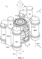
Fig. 1 is a perspective view of a rotary electrohydraulic actuator. -
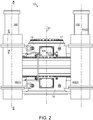
Fig. 2 is a side view of the rotary electrohydraulic actuator as seen in the direction ofarrow 2 ofFig. 1 . -
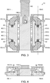
Fig. 3 is a cross-sectional view of the rotary electrohydraulic actuator as along line A-A ofFig. 2 . -
Fig. 4 is a cross-sectional view of the rotary electrohydraulic actuator as along line C-C ofFig. 2 . -
Fig. 5 is a side view of the rotary electrohydraulic actuator as seen in the direction ofarrow 5 ofFig. 1 . -
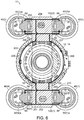
Fig. 6 is a cross-sectional view of the rotary electrohydraulic actuator as along line B-B ofFig. 5 . -
Fig. 7 is a cross-sectional view of a multi-lobe cam ring-type radial piston motor. -
Fig. 8 is a cross-sectional view of a variable displacement plunger pump. - Referring to
Fig. 1 , a rotaryelectrohydraulic actuator 10 includes ahydraulic motor unit 12, and at least onepower plant 40 mounted on thehydraulic motor unit 12 via a manifold 100 that directs hydraulic fluid between thehydraulic motor unit 12 and thepower plant 40. In the illustrated embodiment, two power plants 40(1), 40(4) are mounted on one side of thehydraulic motor unit 12 via a first manifold portion 100(1), and two additional power plants 40(2), 40(3) are mounted on an opposed side of thehydraulic motor unit 12 via a second manifold portion 100(2). The rotaryelectrohydraulic actuator 10 is a direct drive actuator, and is "self-contained" in that the power plants 40(1), 40(2), 40(3), 40(4) that supply hydraulic fluid to thehydraulic motor unit 12 are not remote, and are instead joined directly to thehydraulic motor unit 12. The rotaryelectrohydraulic actuator 10 provides a rotational output suitable for applications that require a driving range with low speed (less than 100 rpm) and high torque (100,000 ft-lbs to 150,000 ft-lbs or more), as well as high speed (200 rpm) and medium torque (4,000 ft-lbs to 50,000 ft-lbs), such as required by top drives or power swivels for drilling rigs or other rotary applications including mud pump actuators. It is understood, however, that the ranges described here are exemplary only, and that the rotaryelectrohydraulic actuator 10 can provide torque and speed combinations beyond those described above, and particularly can provide torque and speed combinations as required for a given application by appropriate scaling of components. - Referring to
Figs. 1 and7 , thehydraulic motor unit 12 is formed of a firsthydraulic motor 14 and a secondhydraulic motor 16 mounted in tandem. The first and secondhydraulic motors hydraulic motors outer cam ring 22 disposed in ahousing 17 that defines ahydraulic fluid inlet 18 and hydraulicfluid outlet 20. Theouter cam ring 22 has an undulatedinner cam surface 23 that faces and surrounds the hydraulic motorrotational axis 32. The first and secondhydraulic motors inner cylinder block 24. Thecylinder block 24 is rotatable about therotational axis 32 in relation to thecam ring 22 and has radially outwardly directedcylinders 28. Apiston 26 is slideably disposed in each of thecylinders 28, and acam roll 30 is associated with eachpiston 26. Eachcam roll 30 is arranged against the correspondingpiston 26, and rolls along and against thecam surface 23. The first and secondhydraulic motors cylinders 28 viaducts 36 in a working stroke of therespective pistons 26 and evacuates the hydraulic fluid from thecylinders 28 in a return stroke of therespective pistons 26. Although thecylinder block 24 andcam ring 22 are illustrated as having five sets ofpistons 26 and cam rolls 30, and a corresponding number of undulations in theouter cam ring 22, thehydraulic motors pistons 26 and cam rolls 30, and the corresponding number of undulations in theouter cam ring 22 may be greater or fewer, and is determined by the requirements of the application. In some hydraulic motors, multiple outer cam rings 22 are provided, each having sets ofpistons 26 and cam rolls 30, and the number of cam rings 22 is determined by the requirements of the application. - Each of the first and second
hydraulic motors cylinder block 24 so as to be concentric with the hydraulic motor unitrotational axis 32. Thecentral openings 34 extend continuously through the respective first and secondhydraulic motors hydraulic motor unit 12. Thecentral openings 34 are configured to receive a driven shaft 8 (shown in broken lines inFig. 1 ) of an external driven device (not shown), and engage the driven shaft 8 via, for example, a spline connection or other appropriate mechanism. The through-openings 34 open on opposed sides of thehydraulic motor unit 12. This configuration allows the driven shaft 8 to extend through thehydraulic motor unit 12 such that opposed ends of the driven shaft 8 are accessible. In other embodiments, in order to accommodate applications that require a male connection to an external driven device, a stub shaft (not shown) may optionally be provided within thecentral openings 34 and fixed to thecylinder block 24. - Referring to
Figs. 2-6 , the rotaryelectrohydraulic actuator 10 includes four power plants 40(1), 40(2), 40(3), 40(4). Each power plant 40(1), 40(2), 40(3), 40(4) is identical, so only one power plant 40(1), hereafter referred to aspower plant 40, will be described. Thepower plant 40 includes anelectric motor 42, and ahydraulic pump 60 disposed at each end of theelectric motor 42. For example, the first power plant 40(1) includes an alpha hydraulic pump 60(1)a at one end of theelectric motor 42, and a beta hydraulic pump 60(1)b at the opposed end. - The
electric motor 42 is a reversible, variable speed, permanent magnet motor having dual female shafts (e.g., dual hollow shafts) 48 arranged collinearly with alongitudinal axis 50 of theelectric motor 42. Theelectric motor 42 includes astator 46, apermanent magnet rotor 44 rotatably disposed within thestator 46 so as to rotate about thelongitudinal axis 50. Afemale shaft 48 is provided at each end of therotor 44. Thefemale shafts 48 are configured to receive and engage aninput shaft 72 of onehydraulic pump 60 of the pair of hydraulic pumps 60(a), 60(b), as discussed further below. Theelectric motor 42 is close-coupled to the hydraulic pumps 60(1)a, 60(1)b. As used herein, close-coupled refers to a configuration in which thepump input shaft 72 is mounted directly on or is formed integrally with the electric motor output shaft, and thus has a gear-free connection to the electric motor output shaft. Use of a close-coupledelectric motor 42 as the driver for thehydraulic pumps 60 in combination with the dualfemale shafts 48 results in a small, compact electric motor unit that is advantageous in applications having small space requirements. - Referring to
Figs. 3 and8 , the alpha and beta hydraulic pumps 60(1)a, 60(1)b are identical, so only one hydraulic pump 60(1)a, hereafter referred to ashydraulic pump 60, will be described. Thehydraulic pump 60 is a variable displacement bent axis piston hydraulic pump that includes a disc shapeddrive plate 74, an input (e.g., driven)shaft 72 rigidly protruding from one side of thedrive plate 74, and ball-tippedpistons 68 rotatably connected about a periphery of an opposed side of thedrive plate 74. The ball tip on a proximal end of eachpiston 68 is received in a spherical socket on the opposed side of thedrive plate 74, whereby thepiston 68 is retained on thedrive plate 74 but is able to rotate relative to thedrive plate 74. A distal end of eachpiston 68 is slidably received within a correspondingcylinder 70 formed in acylinder block 76. The amount of fluid displacement generated by thehydraulic pump 60 can be varied by varying the angle of thecylinder block 76 relative to the longitudinal axis of theinput shaft 72. - The
input shaft 72 may be connected to thefemale shaft 48 of theelectric motor 42, for example via a spline connection or other appropriate mechanism. Theelectric motor 42 drives theinput shaft 72 and driveplate 74 to rotate, whereby hydraulic fluid is distributed to thecylinders 70 in a working stroke of therespective pistons 68 when the piston is moved closer to thecylinder block 76 due to drive plate rotation and evacuates the hydraulic fluid from thecylinders 70 in a return stroke of therespective pistons 68 when the piston is moved away from thecylinder block 76 due to drive plate rotation. - Each of the four power plants 40(1), 40(2), 40(3), 40(4) are secured to the manifold 100 so that the
longitudinal axes 50 of the electric motors are parallel to the hydraulic motor unitrotational axis 32. In addition, each of the four power plants 40(1), 40(2), 40(3), 40(4) are disposed adjacent to a circumferential surface of the hydraulicmotor unit housing 17, whereby thelongitudinal axes 50 of the electric motors are radially spaced apart from the hydraulic motor unitrotational axis 32. This arrangement of the fourelectric motors 42 and thehydraulic motor unit 12 is very compact, especially when compared to an arrangement in which thelongitudinal axes 50 of the electric motors are transverse to the hydraulic motor unitrotational axis 32. - Referring to
Figs. 4-6 , each of the four power plants 40(1), 40(2), 40(3), 40(4) are secured to the manifold 100 in such a way that hydraulicpump fluid inlets 64 and hydraulicpump fluid outlets 66 communicate with a hydraulicfluid path 200 that passes through each of thehydraulic pumps 60 and the first and secondhydraulic motors hydraulic motor unit 12. The hydraulicfluid path 200 is at least partially housed in the manifolds 100(1), 100(2) and is a closed circuit used to direct hydraulic fluid pressurized in thehydraulic pumps 60 to thehydraulic motor unit 12, and return hydraulic fluid discharged from thehydraulic motor unit 12 to the hydraulic pumps 60. - The hydraulic
fluid path 200 includes a series of interconnected fluid path branches configured to provide bi-directional and parallel hydraulic fluid flow into both sides, and out from both sides, of thehydraulic motor unit 12, as will now be described in detail: Hydraulic fluid circulates from theoutlets 66 of the hydraulic pumps 60(1)a, 60(1)b, 60(4)a, 60(4)b of the first and fourth power plants 40(1), 40(4) through afirst branch 201 of the hydraulicfluid path 200. Thefirst branch 201 connects theoutlets 66 of the alpha and beta pumps 60(1)a, 60(1)b of the first power plant 40(1) to theoutlets 66 of the alpha and beta pumps 60(4)a, 60(4)b of the of the fourth power plant 40(4). In addition, thefirst branch 201 connects to a fluid pathsecond branch 202 that directs hydraulic fluid to theinlets 18 of the first and secondhydraulic motors hydraulic motor unit 12. Pressurized hydraulic fluid enters theinlets 18 of the first and secondhydraulic motors rotors 24 of the first and secondhydraulic motors third branch 203 of the hydraulicfluid path 200. - In addition, hydraulic fluid circulates from the
outlets 66 of the hydraulic pumps 60(2)a, 60(2)b, 60(3)a, 60(3)b of the second and third power plants 40(2), 40(3) through afifth branch 205 of the hydraulicfluid path 200. Thefifth branch 205 connects theoutlets 66 of the alpha and beta pumps 60(2)a, 60(2)b of the second power plant 40(2) to theoutlets 66 of the alpha and beta pumps 60(3)a, 60(3)b of the of the third power plant 40(3). In addition, thefifth branch 205 connects to a fluid pathfourth branch 204 that directs hydraulic fluid to theinlets 18 of the first and secondhydraulic motors hydraulic motor unit 12. Pressurized hydraulic fluid enters theinlets 18 of the first and secondhydraulic motors rotors 24 of the first and secondhydraulic motors third branch 203 of the hydraulicfluid path 200. - Hydraulic fluid discharging from
pistons 26 of the first and secondhydraulic motors eighth branch 208 and then exits fromoutlets 20 on the first side of thehydraulic motor unit 12 and passes into a fluid pathninth branch 209. Theninth branch 209 communicates with a fluid pathtenth branch 210. Thetenth branch 210 connects theinlets 64 of the alpha and beta pumps 60(1)a, 60(1)b of the first power plant 40(1) to theinlets 64 of the alpha and beta pumps 60(4)a, 60(4)b of the of the fourth power plant 40(4). - In addition, hydraulic fluid discharging from
pistons 26 of the first and secondhydraulic motors eighth branch 208 and then exits fromoutlets 20 on the second side of thehydraulic motor unit 12 and passes into a fluid pathseventh branch 207. Theseventh branch 207 communicates with a fluid pathsixth branch 206. Thesixth branch 206 connects theinlets 64 of the alpha and beta pumps 60(2)a, 60(2)b of the second power plant 40(2) to theinlets 64 of the alpha and beta pumps 60(3)a, 60(3)b of the of the third power plant 40(3). - The first, second, ninth and
tenth branches fluid path 200 are formed in the first manifold portion 100(1). The second andninth branches seventh branches fluid path 200 are formed in the second manifold portion 100(2). As seen inFig. 5 , the fourth andseventh branches - In some embodiments, the rotary
electrohydraulic actuator 10 includes acharge pump 150 and and/or anauxiliary pump 160 mounted on the manifold 100 so as to communicate with the hydraulicfluid path 200. For example, thecharge pump 150 may be used to maintain a minimum pressure on the back side of the pistons, and theauxiliary pump 160 may be used to circulate a coolant or drive ancillary components of the top drive. The rotaryelectrohydraulic actuator 10 may also include filters (not shown) disposed in the manifold 100 that are configured to remove particulates or other contaminants from the hydraulic fluid. In addition, the rotaryelectrohydraulic actuator 10 may include temperature sensors (not shown), pressure sensors (not shown) and/or other appropriate sensors (not shown) that facilitate monitoring and/or control of the operation of the rotaryelectrohydraulic actuator 10. - The rotary
electrohydraulic actuator 10 including thehydraulic motor unit 12, and at least onepower plant 40 mounted on thehydraulic motor unit 12 via themanifold 100 provides a very powerful and very compact actuator due at least in part to the use of a direct drivehydraulic motor unit 12, the proximate mounting of thepower plant 40 on thehydraulic motor unit 12 whereby hoses and other elongate conduits are omitted, and mounting of theelectric motors 42 within thepower plant 40 so as to be parallel to, and spaced apart from, the rotational axis of thehydraulic motor unit 12. - The rotary
electrohydraulic actuator 10 can be used in a wide variety of applications that require rotary actuation. Although not limited to any particular application, the rotaryelectrohydraulic actuator 10 has obvious advantages for use in drilling machines as part of a top drive or power swivel. For example, the rotary electrohydraulic actuator occupies a much smaller volume within a top drive than do some conventional top drive actuators. In some embodiments, the volume occupied by some conventional top drive actuators having electric motors and gears sets is about twice that of the rotaryelectrohydraulic actuator 10. In addition, the weight of the rotaryelectrohydraulic actuator 10 is much less than that of such conventional top drive actuators. The rotaryelectrohydraulic actuator 10 provides the performance benefits of a conventional hydraulic drive including shock load absorption and improved control while eliminating long conveyance lines and valves. In addition to being used in drilling machines, the rotaryelectrohydraulic actuator 10 may be used in other applications, including, but not limited to, power swivels, winch drives, thruster drives, rotary pump drives, hoist drives, etc. - Although the rotary
electrohydraulic actuator 10 includes four power plants 40(1), 40(2), 40(3), 40(4), the rotaryelectrohydraulic actuator 10 is not limited to having fourpower plants 40, and may include a greater or fewer number ofpower plants 40 as required by the specific application. Moreover, the rotaryelectrohydraulic actuator 10 may be controlled to use a subset of thepower plants 40 provided, depending upon power requirements at a given time. - In the illustrated embodiment, the manifold 100 is configured so that hydraulic fluid from all of the
hydraulic pumps 60 is combined into a single hydraulicfluid path 200 that is used to supply both the first and secondhydraulic motors hydraulic motor unit 12. In other embodiments, the manifold 100 is configured so that fluid from a first subset of pumps (for example, a subset including hydraulic pumps 60(1)a, 60(1)b, 60(4)a, 60(4)b of the first and fourth power plant 40(1), 40(4)) is combined into a first fluid path that is used to supply the firsthydraulic motor 14, and fluid from a second subset of pumps (for example, a subset including hydraulic pumps 60(2)a, 60(2)b, 60(3)a, 60(3)b of the second and third power plant 40(2), 40(3)) is combined into a second fluid path that is used to supply the secondhydraulic motor 16. In some embodiments, the manifold 100 may include valves that can redirect fluid from the secondhydraulic motor 16 to the first hydraulic motor 14 (or vice versa), such that fluid from allpumps 60 flows to a single hydraulic motor, i.e., the firsthydraulic motor 14, providing a higher speed, lower torque configuration. Thus, the rotaryelectrohydraulic actuator 10 can be configured as a gear free, two speed motor. - In the illustrated embodiment, the first and second manifolds 100(1), 100(2) are external to and supported on the
hydraulic motors hydraulic motors - In some embodiments, the hydraulic fluid used in the manifold 100 is biodegradable. In some embodiments, the hydraulic fluid also serves as a coolant for the
hydraulic motors hydraulic pumps 60 and theelectric motors 42. - In the illustrated embodiment, the
electric motor 42 used in eachpower plant 40 is a reversible, variable speed, permanent magnet motor having dual female shafts (e.g., dual hollow shafts) 48. However, theelectric motor 42 is not limited to this type of motor and any appropriate motor can be used including those that are non-reversible and/or constant speed. Moreover, the type of electric motor used in one or more power plants (i.e., power plants 40(1), 40(3)) may be different than the type of electric motor used in the remaining power plants (i.e., power plants 40(2). 40(4)). - In the illustrated embodiment, the alpha and beta hydraulic pumps 60(1)a, 60(1)b used in each power plant 40(1) are variable displacement bent axis piston hydraulic pumps. However, the alpha and beta hydraulic pumps 60(1)a, 60(1)b are not limited to this type of pump and any appropriate pump can be used including those that are straight axis, fixed displacement and/or of gear, rotary vane, screw, radial piston or other type. Moreover, the type of hydraulic pump used as the alpha hydraulic pump 60(1)a may be different than the type of hydraulic pump used as the beta hydraulic pump 60(1)b. In addition, or alternatively, the types of pumps used in one or more power plants (i.e., power plants 40(1), 40(3)) may be different than the types of pumps used in the remaining power plants (i.e., power plants 40(2). 40(4)).
- In the illustrated embodiment, the
hydraulic motors hydraulic motors - Selective illustrative embodiments of the rotary electrohydraulic actuator are described above in some detail. It should be understood that only structures considered necessary for clarifying this device has been described herein. Other conventional structures, and those of ancillary and auxiliary components of the actuator system, are assumed to be known and understood by those skilled in the art. Moreover, while working examples of the rotary electrohydraulic actuator has been described above, the rotary electrohydraulic actuator is not limited to the working examples described above, but various design alterations may be carried out without departing from the devices as set forth in the claims.
Claims (13)
- A rotary electrohydraulic actuator (10) comprisinga hydraulic drive unit (12) comprising a first hydraulic motor (14), a second hydraulic motor (16) that is mounted in tandem with the first hydraulic motor (14), each hydraulic motor (14, 16) including a hydraulic motor housing (17) having a fluid inlet (18) and a fluid outlet (20), and a rotor disposed in the hydraulic motor housing (17) so as to rotate about a rotational axis (32), the rotor including a through opening (34) that is centered on the rotational axis (32) and serves as a hollow output shaft of the hydraulic motor (14, 16), whereby the output shaft provides a gear-free connection to a driven shaft when a driven shaft is disposed in the through opening (34), wherein the first hydraulic motor (14) and the second hydraulic motor (16) share the same rotational axis (32);a manifold (100) that defines a fluid path (200) between the fluid inlets (18) and the fluid outlets (20), the manifold (100) connected to the hydraulic motor housings (17) in such a way as to permit the fluid path (200) to communicate with the fluid inlets (18) and the fluid outlets (20) and the manifold (100) to be spaced apart from the rotational axis (32); andat least two power plants (40), each including a hydraulic pump (60) disposed in the fluid path (200) and an electric dual shaft motor (42) that is configured to drive the hydraulic pump (60), wherein the hydraulic pump (60) comprises a first hydraulic pump (60a) and a second hydraulic pump (60b), and the first hydraulic pump (60a) is driven by a first shaft of the dual shaft electric motor (42), and the second hydraulic pump (60b) is driven by a second shaft of the dual shaft electric motor (42), and wherein operation of the electric motor (42) causes the hydraulic pump (60) to supply pressurized fluid to the fluid inlets (18) of the hydraulic motors (14, 16);wherein each power plant (40) is oriented so that the first shaft and the second shaft are non-intersecting with the rotational axis (32), and each power plant (40) is secured to the manifold (100) such that each fluid inlet (64) of each hydraulic pump (60a, 60b) and each fluid outlet (66) of each hydraulic pump (60a, 60b) communicates with the fluid path (200), wherein the fluid path (200) passes through each of the first hydraulic motor (14) and the second hydraulic motor (16), andwherein at least one power plant (40) is mounted on the hydraulic drive unit (12) via the manifold (100).
- The rotary electrohydraulic actuator (10) of claim 1, wherein the electric motor output shaft defines an electric motor longitudinal axis (50), and the electric motor (42) is arranged so that the electric motor longitudinal axis (50) is non-intersecting with the rotational axis (32).
- The rotary electrohydraulic actuator (10) of claim 1, wherein the electric motor output shaft defines an electric motor longitudinal axis (50), and the electric motor (42) is arranged so that the electric motor longitudinal axis (50) is parallel to, and spaced apart from, the rotational axis (32).
- The rotary electrohydraulic actuator (10) of claim 1, wherein a pump input shaft (72) of the hydraulic pump (60) is mounted directly on or is formed integrally with an electric motor output shaft of the electric motor (42).
- The rotary electrohydraulic actuator (10) of claim 1, wherein the manifold (100) comprises a first manifold portion (100(1)) and a second manifold portion (100(2)), and the first manifold portion (100(1)) is disposed on an opposed side of the hydraulic drive unit (12) relative to the second manifold portion (100(2)), and each of the first and second manifold portions (100(1), (100(2)) is connected to a unique fluid inlet (18) of the hydraulic motor (14, 16) and a unique fluid outlet (20) of the hydraulic motor (14, 16).
- The rotary electrohydraulic actuator (10) of claim 1, wherein the through opening (34) extends through the hydraulic motor housing (17) and opens on opposed sides of the hydraulic motor housing (17).
- The rotary electrohydraulic actuator (10) of claim 1, wherein the fluid path (200) can be switched between a first configuration in which the hydraulic motor (14, 16) operates at a first speed, and a second configuration in which the hydraulic motor (14, 16) operates at a second speed that is different than the first speed.
- The rotary electrohydraulic actuator (10) of claim 1, wherein the fluid path (200) includes a series of interconnected fluid path branches that are configured to provide bi-directional and parallel hydraulic fluid flow into, and out of, each of the first hydraulic motor (14) and the second hydraulic motor (16).
- The rotary electrohydraulic actuator (10) of claim 1, wherein the hydraulic motor (14, 16) is a straight axis motor.
- A driving mechanism, comprisinga rotary electrohydraulic actuator (10) according to claim 1,an output shaft disposed in the through opening (34); anda frame that supports the rotary electrohydraulic actuator (10) relative to a support surface.
- The driving mechanism of claim 10, whereinthe output shaft is mechanically connected to a drill string, andthe frame supports the rotary electrohydraulic actuator (10) for movement along a frame longitudinal axis.
- The driving mechanism of claim 10, whereinthe output shaft is mechanically connected to a secondary pump that is configured to pump a slurry, andthe frame supports the rotary electrohydraulic actuator (10) in a fixed position relative to the secondary pump.
- The driving mechanism of claim 10, comprising a spool, whereinthe spool has a cylindrical outer surface and a spool rotational axis centered within the cylindrical outer surface,the output shaft is mechanically connected to the spool in such a way that the output shaft drives the spool to rotate about the spool rotational axis (32), andthe frame supports the spool and the rotary electrohydraulic actuator (10) such that the spool rotates relative to the rotary electrohydraulic actuator (10).
Applications Claiming Priority (2)
| Application Number | Priority Date | Filing Date | Title |
|---|---|---|---|
| US201662395484P | 2016-09-16 | 2016-09-16 | |
| PCT/EP2017/071952 WO2018050452A1 (en) | 2016-09-16 | 2017-09-01 | Rotary electrohydraulic actuator |
Publications (2)
| Publication Number | Publication Date |
|---|---|
| EP3513029A1 EP3513029A1 (en) | 2019-07-24 |
| EP3513029B1 true EP3513029B1 (en) | 2020-06-03 |
Family
ID=59887218
Family Applications (1)
| Application Number | Title | Priority Date | Filing Date |
|---|---|---|---|
| EP17768037.8A Active EP3513029B1 (en) | 2016-09-16 | 2017-09-01 | Rotary electrohydraulic actuator |
Country Status (4)
| Country | Link |
|---|---|
| US (1) | US10982743B2 (en) |
| EP (1) | EP3513029B1 (en) |
| RU (1) | RU2749519C2 (en) |
| WO (1) | WO2018050452A1 (en) |
Families Citing this family (3)
| Publication number | Priority date | Publication date | Assignee | Title |
|---|---|---|---|---|
| US11031149B1 (en) * | 2018-02-13 | 2021-06-08 | AGI Engineering, Inc. | Nuclear abrasive slurry waste pump with backstop and macerator |
| NO20231173A1 (en) | 2021-06-04 | 2023-11-02 | Schlumberger Technology Bv | Electric blowout preventer bonnet using linear actuated roller screws |
| US12163391B2 (en) | 2023-03-20 | 2024-12-10 | Baker Hughes Oilfield Operations Llc | Modular actuator, method, and system |
Family Cites Families (30)
| Publication number | Priority date | Publication date | Assignee | Title |
|---|---|---|---|---|
| US2709071A (en) | 1949-12-03 | 1955-05-24 | Frederic W Hild | Hydro-gear retrieving feed apparatus for rotary drilling |
| US2762339A (en) * | 1952-12-04 | 1956-09-11 | Schroeder Brothers | Hydraulic drill |
| US2891771A (en) * | 1955-07-05 | 1959-06-23 | Youngstown Sheet And Tube Co | Hydraulically driven rotary machine |
| US3448627A (en) | 1967-05-19 | 1969-06-10 | Jerry R Brooks | Gearless variable drive mechanism |
| SU510351A1 (en) * | 1974-03-25 | 1976-04-15 | Московский Машиностроительный Завод "Салют" | Electro-hydraulic drive vibratory drilling machine with software control |
| US3986564A (en) * | 1975-03-03 | 1976-10-19 | Bender Emil A | Well rig |
| US3979295A (en) | 1975-04-09 | 1976-09-07 | The United States Of America As Represented By The United States Energy Research And Development Administration | Folded membrane dialyzer with mechanically sealed edges |
| US4242057A (en) | 1979-09-24 | 1980-12-30 | Bender Emil A | Tandem long stroke reciprocating mud pump assembly |
| US4813943A (en) | 1987-08-17 | 1989-03-21 | Smith Samuel C | Urinary incontinence collector |
| US5176364A (en) | 1990-08-30 | 1993-01-05 | Camo International Inc. | Direct drive hydraulic wireline winch assembly |
| DE59405708D1 (en) * | 1993-10-19 | 1998-05-20 | Voith Gmbh J M | Hydrostatic radial piston machine with axial thrust compensation |
| US5755296A (en) | 1994-09-13 | 1998-05-26 | Nabors Industries, Inc. | Portable top drive |
| RU2105861C1 (en) | 1995-04-28 | 1998-02-27 | Анатолий Иванович Литвинов | Top-driven drilling device |
| SE517873C2 (en) | 1997-04-10 | 2002-07-30 | Haegglunds Drives Ab | Piston for a hydraulic radial piston motor and hydraulic radial motor with such piston |
| CA2390365C (en) | 2002-07-03 | 2003-11-11 | Shawn James Nielsen | A top drive well drilling apparatus |
| AU2002952079A0 (en) * | 2002-10-16 | 2002-10-31 | Darrell Ballantyne Copeman | Winch |
| US7188686B2 (en) | 2004-06-07 | 2007-03-13 | Varco I/P, Inc. | Top drive systems |
| MX2008008271A (en) | 2005-12-20 | 2008-09-03 | Canrig Drilling Tech Ltd | Modular top drive. |
| US8109179B2 (en) | 2008-02-12 | 2012-02-07 | Allan Stewart Richardson | Power tong |
| WO2010056385A1 (en) | 2008-11-14 | 2010-05-20 | Williams Kevin R | Permanent magnet direct drive top drive |
| CN201598974U (en) | 2010-01-30 | 2010-10-06 | 徐州博汇东明机械制造有限公司 | Twin-engine power device of large rotary drilling rig |
| US20110214919A1 (en) | 2010-03-05 | 2011-09-08 | Mcclung Iii Guy L | Dual top drive systems and methods |
| PE20130791A1 (en) * | 2010-04-07 | 2013-07-25 | Weir Minerals Netherlands Bv | PHASE DISPLACEMENT CONTROLLER FOR AN ALTERNATIVE PUMP SYSTEM |
| US20130180217A1 (en) * | 2012-01-14 | 2013-07-18 | Ronda Brubaker | Sandwich Separator Container |
| FR2985786B1 (en) * | 2012-01-18 | 2016-11-25 | Poclain Hydraulics Ind | HYDRAULIC TRANSMISSION CIRCUIT WITH MULTIPLE CYLINDER |
| EP2770218A3 (en) | 2013-02-26 | 2017-04-26 | Actuant Corporation | A self-contained electro-hydraulic bidirectional rotary actuator unit |
| US9493985B2 (en) * | 2013-07-23 | 2016-11-15 | National Oilwell Varco, L.P. | Mud hydraulic top drive |
| CN203783839U (en) | 2013-12-30 | 2014-08-20 | 三一重型能源装备有限公司 | Fracturing pump transmission system and fracturing truck |
| DE102014200191A1 (en) | 2014-01-09 | 2015-07-09 | Robert Bosch Gmbh | Hydrostatic primary unit for a hydrostatic transmission and hydrostatic transmission |
| RU2593325C1 (en) * | 2015-09-07 | 2016-08-10 | Акционерное общество "Всероссийский научно-исследовательский институт "Сигнал" (АО "ВНИИ "Сигнал") | Hydroelectric drive |
-
2017
- 2017-09-01 US US16/331,492 patent/US10982743B2/en active Active
- 2017-09-01 RU RU2019110678A patent/RU2749519C2/en active
- 2017-09-01 WO PCT/EP2017/071952 patent/WO2018050452A1/en not_active Ceased
- 2017-09-01 EP EP17768037.8A patent/EP3513029B1/en active Active
Non-Patent Citations (1)
| Title |
|---|
| None * |
Also Published As
| Publication number | Publication date |
|---|---|
| WO2018050452A1 (en) | 2018-03-22 |
| US20190195020A1 (en) | 2019-06-27 |
| EP3513029A1 (en) | 2019-07-24 |
| RU2749519C2 (en) | 2021-06-11 |
| RU2019110678A3 (en) | 2020-12-21 |
| RU2019110678A (en) | 2020-10-16 |
| US10982743B2 (en) | 2021-04-20 |
Similar Documents
| Publication | Publication Date | Title |
|---|---|---|
| EP3467209B1 (en) | Excavation tool for making diaphragms and related excavation equipment | |
| KR101664646B1 (en) | Gear pump or hydraulic gear motor with helical toothing provided with hydraulic system for axial thrust balance | |
| EP2261499B1 (en) | Electric motor integrated hydraulic motor | |
| JP5890987B2 (en) | Electric hydraulic actuator | |
| EP2848808B1 (en) | Fluid pressure drive unit | |
| US10982743B2 (en) | Rotary electrohydraulic actuator | |
| EP2848809A1 (en) | Fluid pressure drive unit | |
| WO2001079697A2 (en) | Variable speed hydraulic pump | |
| WO2008132503A2 (en) | Improvements in or relating to drawworks | |
| US10487657B2 (en) | Hydraulic machine | |
| US5033265A (en) | Coaxial hydraulic actuator system | |
| CN102066773A (en) | Electro-hydraulic actuator with pump incorporated into the piston | |
| KR102702111B1 (en) | Lobe pump with internal bearings | |
| US20050226757A1 (en) | Variable capacity pump/motor | |
| EP1978248B1 (en) | Pump Equipment | |
| WO2001012996A8 (en) | Power unit for positioning valves, or the like, into desired position | |
| EP2116743B1 (en) | Variable belt drive | |
| JP2002317774A (en) | Oil pressure changer using a pair of variable displacement gear pump | |
| US7682136B2 (en) | Multiple pump housing | |
| CN213116929U (en) | Precise hydraulic roller, hydraulic motor and low-speed high-torque hydraulic system | |
| EP3105013B1 (en) | Torque tool, motor assembly, and methods of use | |
| EP1840027A1 (en) | Improved drive unit, particularly for boats | |
| EP4133179B1 (en) | Assistive torque electro-hydraulic piston pump system | |
| US8616528B2 (en) | Integrated hydraulic motor and winch | |
| CN212985443U (en) | Hydraulic motor with double-shaft output |
Legal Events
| Date | Code | Title | Description |
|---|---|---|---|
| STAA | Information on the status of an ep patent application or granted ep patent |
Free format text: STATUS: UNKNOWN |
|
| STAA | Information on the status of an ep patent application or granted ep patent |
Free format text: STATUS: THE INTERNATIONAL PUBLICATION HAS BEEN MADE |
|
| PUAI | Public reference made under article 153(3) epc to a published international application that has entered the european phase |
Free format text: ORIGINAL CODE: 0009012 |
|
| STAA | Information on the status of an ep patent application or granted ep patent |
Free format text: STATUS: REQUEST FOR EXAMINATION WAS MADE |
|
| 17P | Request for examination filed |
Effective date: 20190416 |
|
| AK | Designated contracting states |
Kind code of ref document: A1 Designated state(s): AL AT BE BG CH CY CZ DE DK EE ES FI FR GB GR HR HU IE IS IT LI LT LU LV MC MK MT NL NO PL PT RO RS SE SI SK SM TR |
|
| AX | Request for extension of the european patent |
Extension state: BA ME |
|
| DAV | Request for validation of the european patent (deleted) | ||
| DAX | Request for extension of the european patent (deleted) | ||
| GRAP | Despatch of communication of intention to grant a patent |
Free format text: ORIGINAL CODE: EPIDOSNIGR1 |
|
| STAA | Information on the status of an ep patent application or granted ep patent |
Free format text: STATUS: GRANT OF PATENT IS INTENDED |
|
| INTG | Intention to grant announced |
Effective date: 20200116 |
|
| GRAS | Grant fee paid |
Free format text: ORIGINAL CODE: EPIDOSNIGR3 |
|
| RAP1 | Party data changed (applicant data changed or rights of an application transferred) |
Owner name: ROBERT BOSCH GMBH |
|
| GRAA | (expected) grant |
Free format text: ORIGINAL CODE: 0009210 |
|
| STAA | Information on the status of an ep patent application or granted ep patent |
Free format text: STATUS: THE PATENT HAS BEEN GRANTED |
|
| AK | Designated contracting states |
Kind code of ref document: B1 Designated state(s): AL AT BE BG CH CY CZ DE DK EE ES FI FR GB GR HR HU IE IS IT LI LT LU LV MC MK MT NL NO PL PT RO RS SE SI SK SM TR |
|
| REG | Reference to a national code |
Ref country code: GB Ref legal event code: FG4D |
|
| REG | Reference to a national code |
Ref country code: CH Ref legal event code: EP Ref country code: AT Ref legal event code: REF Ref document number: 1277191 Country of ref document: AT Kind code of ref document: T Effective date: 20200615 |
|
| REG | Reference to a national code |
Ref country code: DE Ref legal event code: R096 Ref document number: 602017017781 Country of ref document: DE |
|
| REG | Reference to a national code |
Ref country code: LT Ref legal event code: MG4D |
|
| PG25 | Lapsed in a contracting state [announced via postgrant information from national office to epo] |
Ref country code: SE Free format text: LAPSE BECAUSE OF FAILURE TO SUBMIT A TRANSLATION OF THE DESCRIPTION OR TO PAY THE FEE WITHIN THE PRESCRIBED TIME-LIMIT Effective date: 20200603 Ref country code: FI Free format text: LAPSE BECAUSE OF FAILURE TO SUBMIT A TRANSLATION OF THE DESCRIPTION OR TO PAY THE FEE WITHIN THE PRESCRIBED TIME-LIMIT Effective date: 20200603 Ref country code: NO Free format text: LAPSE BECAUSE OF FAILURE TO SUBMIT A TRANSLATION OF THE DESCRIPTION OR TO PAY THE FEE WITHIN THE PRESCRIBED TIME-LIMIT Effective date: 20200903 Ref country code: GR Free format text: LAPSE BECAUSE OF FAILURE TO SUBMIT A TRANSLATION OF THE DESCRIPTION OR TO PAY THE FEE WITHIN THE PRESCRIBED TIME-LIMIT Effective date: 20200904 Ref country code: LT Free format text: LAPSE BECAUSE OF FAILURE TO SUBMIT A TRANSLATION OF THE DESCRIPTION OR TO PAY THE FEE WITHIN THE PRESCRIBED TIME-LIMIT Effective date: 20200603 |
|
| REG | Reference to a national code |
Ref country code: NL Ref legal event code: MP Effective date: 20200603 |
|
| PG25 | Lapsed in a contracting state [announced via postgrant information from national office to epo] |
Ref country code: LV Free format text: LAPSE BECAUSE OF FAILURE TO SUBMIT A TRANSLATION OF THE DESCRIPTION OR TO PAY THE FEE WITHIN THE PRESCRIBED TIME-LIMIT Effective date: 20200603 Ref country code: RS Free format text: LAPSE BECAUSE OF FAILURE TO SUBMIT A TRANSLATION OF THE DESCRIPTION OR TO PAY THE FEE WITHIN THE PRESCRIBED TIME-LIMIT Effective date: 20200603 Ref country code: BG Free format text: LAPSE BECAUSE OF FAILURE TO SUBMIT A TRANSLATION OF THE DESCRIPTION OR TO PAY THE FEE WITHIN THE PRESCRIBED TIME-LIMIT Effective date: 20200903 Ref country code: HR Free format text: LAPSE BECAUSE OF FAILURE TO SUBMIT A TRANSLATION OF THE DESCRIPTION OR TO PAY THE FEE WITHIN THE PRESCRIBED TIME-LIMIT Effective date: 20200603 |
|
| REG | Reference to a national code |
Ref country code: AT Ref legal event code: MK05 Ref document number: 1277191 Country of ref document: AT Kind code of ref document: T Effective date: 20200603 |
|
| REG | Reference to a national code |
Ref country code: NO Ref legal event code: MMEP |
|
| PG25 | Lapsed in a contracting state [announced via postgrant information from national office to epo] |
Ref country code: NL Free format text: LAPSE BECAUSE OF FAILURE TO SUBMIT A TRANSLATION OF THE DESCRIPTION OR TO PAY THE FEE WITHIN THE PRESCRIBED TIME-LIMIT Effective date: 20200603 Ref country code: AL Free format text: LAPSE BECAUSE OF FAILURE TO SUBMIT A TRANSLATION OF THE DESCRIPTION OR TO PAY THE FEE WITHIN THE PRESCRIBED TIME-LIMIT Effective date: 20200603 |
|
| PGFP | Annual fee paid to national office [announced via postgrant information from national office to epo] |
Ref country code: NL Payment date: 20201020 Year of fee payment: 4 |
|
| REG | Reference to a national code |
Ref country code: NO Ref legal event code: RE Free format text: 'PATENT OPPRETTHOLDES ELLER SAKSBEHANDLINGEN FORTSETTER TIL TROSS FOR FRISTOVERSITTELSE'" |
|
| PG25 | Lapsed in a contracting state [announced via postgrant information from national office to epo] |
Ref country code: RO Free format text: LAPSE BECAUSE OF FAILURE TO SUBMIT A TRANSLATION OF THE DESCRIPTION OR TO PAY THE FEE WITHIN THE PRESCRIBED TIME-LIMIT Effective date: 20200603 Ref country code: PT Free format text: LAPSE BECAUSE OF FAILURE TO SUBMIT A TRANSLATION OF THE DESCRIPTION OR TO PAY THE FEE WITHIN THE PRESCRIBED TIME-LIMIT Effective date: 20201006 Ref country code: IT Free format text: LAPSE BECAUSE OF FAILURE TO SUBMIT A TRANSLATION OF THE DESCRIPTION OR TO PAY THE FEE WITHIN THE PRESCRIBED TIME-LIMIT Effective date: 20200603 Ref country code: CZ Free format text: LAPSE BECAUSE OF FAILURE TO SUBMIT A TRANSLATION OF THE DESCRIPTION OR TO PAY THE FEE WITHIN THE PRESCRIBED TIME-LIMIT Effective date: 20200603 Ref country code: SM Free format text: LAPSE BECAUSE OF FAILURE TO SUBMIT A TRANSLATION OF THE DESCRIPTION OR TO PAY THE FEE WITHIN THE PRESCRIBED TIME-LIMIT Effective date: 20200603 Ref country code: EE Free format text: LAPSE BECAUSE OF FAILURE TO SUBMIT A TRANSLATION OF THE DESCRIPTION OR TO PAY THE FEE WITHIN THE PRESCRIBED TIME-LIMIT Effective date: 20200603 Ref country code: AT Free format text: LAPSE BECAUSE OF FAILURE TO SUBMIT A TRANSLATION OF THE DESCRIPTION OR TO PAY THE FEE WITHIN THE PRESCRIBED TIME-LIMIT Effective date: 20200603 Ref country code: ES Free format text: LAPSE BECAUSE OF FAILURE TO SUBMIT A TRANSLATION OF THE DESCRIPTION OR TO PAY THE FEE WITHIN THE PRESCRIBED TIME-LIMIT Effective date: 20200603 |
|
| PG25 | Lapsed in a contracting state [announced via postgrant information from national office to epo] |
Ref country code: SK Free format text: LAPSE BECAUSE OF FAILURE TO SUBMIT A TRANSLATION OF THE DESCRIPTION OR TO PAY THE FEE WITHIN THE PRESCRIBED TIME-LIMIT Effective date: 20200603 Ref country code: PL Free format text: LAPSE BECAUSE OF FAILURE TO SUBMIT A TRANSLATION OF THE DESCRIPTION OR TO PAY THE FEE WITHIN THE PRESCRIBED TIME-LIMIT Effective date: 20200603 Ref country code: IS Free format text: LAPSE BECAUSE OF FAILURE TO SUBMIT A TRANSLATION OF THE DESCRIPTION OR TO PAY THE FEE WITHIN THE PRESCRIBED TIME-LIMIT Effective date: 20201003 |
|
| REG | Reference to a national code |
Ref country code: DE Ref legal event code: R097 Ref document number: 602017017781 Country of ref document: DE |
|
| REG | Reference to a national code |
Ref country code: NO Ref legal event code: T2 Effective date: 20200603 |
|
| PLBE | No opposition filed within time limit |
Free format text: ORIGINAL CODE: 0009261 |
|
| STAA | Information on the status of an ep patent application or granted ep patent |
Free format text: STATUS: NO OPPOSITION FILED WITHIN TIME LIMIT |
|
| PG25 | Lapsed in a contracting state [announced via postgrant information from national office to epo] |
Ref country code: DK Free format text: LAPSE BECAUSE OF FAILURE TO SUBMIT A TRANSLATION OF THE DESCRIPTION OR TO PAY THE FEE WITHIN THE PRESCRIBED TIME-LIMIT Effective date: 20200603 Ref country code: NO Free format text: LAPSE BECAUSE OF FAILURE TO SUBMIT A TRANSLATION OF THE DESCRIPTION OR TO PAY THE FEE WITHIN THE PRESCRIBED TIME-LIMIT Effective date: 20200903 |
|
| PGRI | Patent reinstated in contracting state [announced from national office to epo] |
Ref country code: NO Effective date: 20201209 |
|
| REG | Reference to a national code |
Ref country code: CH Ref legal event code: PL |
|
| 26N | No opposition filed |
Effective date: 20210304 |
|
| PG25 | Lapsed in a contracting state [announced via postgrant information from national office to epo] |
Ref country code: SI Free format text: LAPSE BECAUSE OF FAILURE TO SUBMIT A TRANSLATION OF THE DESCRIPTION OR TO PAY THE FEE WITHIN THE PRESCRIBED TIME-LIMIT Effective date: 20200603 |
|
| REG | Reference to a national code |
Ref country code: BE Ref legal event code: MM Effective date: 20200930 |
|
| PG25 | Lapsed in a contracting state [announced via postgrant information from national office to epo] |
Ref country code: LU Free format text: LAPSE BECAUSE OF NON-PAYMENT OF DUE FEES Effective date: 20200901 |
|
| PG25 | Lapsed in a contracting state [announced via postgrant information from national office to epo] |
Ref country code: FR Free format text: LAPSE BECAUSE OF NON-PAYMENT OF DUE FEES Effective date: 20200930 |
|
| PG25 | Lapsed in a contracting state [announced via postgrant information from national office to epo] |
Ref country code: BE Free format text: LAPSE BECAUSE OF NON-PAYMENT OF DUE FEES Effective date: 20200930 Ref country code: CH Free format text: LAPSE BECAUSE OF NON-PAYMENT OF DUE FEES Effective date: 20200930 Ref country code: IE Free format text: LAPSE BECAUSE OF NON-PAYMENT OF DUE FEES Effective date: 20200901 Ref country code: LI Free format text: LAPSE BECAUSE OF NON-PAYMENT OF DUE FEES Effective date: 20200930 |
|
| GBPC | Gb: european patent ceased through non-payment of renewal fee |
Effective date: 20210901 |
|
| PG25 | Lapsed in a contracting state [announced via postgrant information from national office to epo] |
Ref country code: TR Free format text: LAPSE BECAUSE OF FAILURE TO SUBMIT A TRANSLATION OF THE DESCRIPTION OR TO PAY THE FEE WITHIN THE PRESCRIBED TIME-LIMIT Effective date: 20200603 Ref country code: MT Free format text: LAPSE BECAUSE OF FAILURE TO SUBMIT A TRANSLATION OF THE DESCRIPTION OR TO PAY THE FEE WITHIN THE PRESCRIBED TIME-LIMIT Effective date: 20200603 Ref country code: CY Free format text: LAPSE BECAUSE OF FAILURE TO SUBMIT A TRANSLATION OF THE DESCRIPTION OR TO PAY THE FEE WITHIN THE PRESCRIBED TIME-LIMIT Effective date: 20200603 |
|
| PG25 | Lapsed in a contracting state [announced via postgrant information from national office to epo] |
Ref country code: MK Free format text: LAPSE BECAUSE OF FAILURE TO SUBMIT A TRANSLATION OF THE DESCRIPTION OR TO PAY THE FEE WITHIN THE PRESCRIBED TIME-LIMIT Effective date: 20200603 Ref country code: MC Free format text: LAPSE BECAUSE OF FAILURE TO SUBMIT A TRANSLATION OF THE DESCRIPTION OR TO PAY THE FEE WITHIN THE PRESCRIBED TIME-LIMIT Effective date: 20200603 |
|
| PG25 | Lapsed in a contracting state [announced via postgrant information from national office to epo] |
Ref country code: GB Free format text: LAPSE BECAUSE OF NON-PAYMENT OF DUE FEES Effective date: 20210901 |
|
| PGFP | Annual fee paid to national office [announced via postgrant information from national office to epo] |
Ref country code: NO Payment date: 20250919 Year of fee payment: 9 |
|
| PGFP | Annual fee paid to national office [announced via postgrant information from national office to epo] |
Ref country code: DE Payment date: 20251121 Year of fee payment: 9 |