EP3512326B1 - Container having an access door latching system - Google Patents
Container having an access door latching system Download PDFInfo
- Publication number
- EP3512326B1 EP3512326B1 EP17851512.8A EP17851512A EP3512326B1 EP 3512326 B1 EP3512326 B1 EP 3512326B1 EP 17851512 A EP17851512 A EP 17851512A EP 3512326 B1 EP3512326 B1 EP 3512326B1
- Authority
- EP
- European Patent Office
- Prior art keywords
- door
- container
- catch
- latch
- walls
- Prior art date
- Legal status (The legal status is an assumption and is not a legal conclusion. Google has not performed a legal analysis and makes no representation as to the accuracy of the status listed.)
- Active
Links
Images








Classifications
-
- B—PERFORMING OPERATIONS; TRANSPORTING
- B65—CONVEYING; PACKING; STORING; HANDLING THIN OR FILAMENTARY MATERIAL
- B65D—CONTAINERS FOR STORAGE OR TRANSPORT OF ARTICLES OR MATERIALS, e.g. BAGS, BARRELS, BOTTLES, BOXES, CANS, CARTONS, CRATES, DRUMS, JARS, TANKS, HOPPERS, FORWARDING CONTAINERS; ACCESSORIES, CLOSURES, OR FITTINGS THEREFOR; PACKAGING ELEMENTS; PACKAGES
- B65D11/00—Containers having bodies formed by interconnecting or uniting two or more rigid, or substantially rigid, components made wholly or mainly of plastics material
- B65D11/18—Containers having bodies formed by interconnecting or uniting two or more rigid, or substantially rigid, components made wholly or mainly of plastics material collapsible, i.e. with walls hinged together or detachably connected
- B65D11/1833—Containers having bodies formed by interconnecting or uniting two or more rigid, or substantially rigid, components made wholly or mainly of plastics material collapsible, i.e. with walls hinged together or detachably connected whereby all side walls are hingedly connected to the base panel
-
- B—PERFORMING OPERATIONS; TRANSPORTING
- B65—CONVEYING; PACKING; STORING; HANDLING THIN OR FILAMENTARY MATERIAL
- B65D—CONTAINERS FOR STORAGE OR TRANSPORT OF ARTICLES OR MATERIALS, e.g. BAGS, BARRELS, BOTTLES, BOXES, CANS, CARTONS, CRATES, DRUMS, JARS, TANKS, HOPPERS, FORWARDING CONTAINERS; ACCESSORIES, CLOSURES, OR FITTINGS THEREFOR; PACKAGING ELEMENTS; PACKAGES
- B65D21/00—Nestable, stackable or joinable containers; Containers of variable capacity
- B65D21/02—Containers specially shaped, or provided with fittings or attachments, to facilitate nesting, stacking, or joining together
- B65D21/0209—Containers specially shaped, or provided with fittings or attachments, to facilitate nesting, stacking, or joining together stackable or joined together one-upon-the-other in the upright or upside-down position
-
- B—PERFORMING OPERATIONS; TRANSPORTING
- B65—CONVEYING; PACKING; STORING; HANDLING THIN OR FILAMENTARY MATERIAL
- B65D—CONTAINERS FOR STORAGE OR TRANSPORT OF ARTICLES OR MATERIALS, e.g. BAGS, BARRELS, BOTTLES, BOXES, CANS, CARTONS, CRATES, DRUMS, JARS, TANKS, HOPPERS, FORWARDING CONTAINERS; ACCESSORIES, CLOSURES, OR FITTINGS THEREFOR; PACKAGING ELEMENTS; PACKAGES
- B65D21/00—Nestable, stackable or joinable containers; Containers of variable capacity
- B65D21/08—Containers of variable capacity
- B65D21/086—Collapsible or telescopic containers
-
- B—PERFORMING OPERATIONS; TRANSPORTING
- B65—CONVEYING; PACKING; STORING; HANDLING THIN OR FILAMENTARY MATERIAL
- B65D—CONTAINERS FOR STORAGE OR TRANSPORT OF ARTICLES OR MATERIALS, e.g. BAGS, BARRELS, BOTTLES, BOXES, CANS, CARTONS, CRATES, DRUMS, JARS, TANKS, HOPPERS, FORWARDING CONTAINERS; ACCESSORIES, CLOSURES, OR FITTINGS THEREFOR; PACKAGING ELEMENTS; PACKAGES
- B65D25/00—Details of other kinds or types of rigid or semi-rigid containers
- B65D25/54—Inspection openings or windows
-
- B—PERFORMING OPERATIONS; TRANSPORTING
- B65—CONVEYING; PACKING; STORING; HANDLING THIN OR FILAMENTARY MATERIAL
- B65D—CONTAINERS FOR STORAGE OR TRANSPORT OF ARTICLES OR MATERIALS, e.g. BAGS, BARRELS, BOTTLES, BOXES, CANS, CARTONS, CRATES, DRUMS, JARS, TANKS, HOPPERS, FORWARDING CONTAINERS; ACCESSORIES, CLOSURES, OR FITTINGS THEREFOR; PACKAGING ELEMENTS; PACKAGES
- B65D85/00—Containers, packaging elements or packages, specially adapted for particular articles or materials
- B65D85/30—Containers, packaging elements or packages, specially adapted for particular articles or materials for articles particularly sensitive to damage by shock or pressure
- B65D85/34—Containers, packaging elements or packages, specially adapted for particular articles or materials for articles particularly sensitive to damage by shock or pressure for fruit, e.g. apples, oranges or tomatoes
Definitions
- Containers especially containers having an access door for accessing an interior of the container.
- Bananas are harvested from trees in tropical growing regions such as Central and South America. Bananas to be exported are picked green, shipped to distribution centers in consuming regions, and delivered to retail stores in a state of ripeness appropriate for retail sale. Conventionally, growers pack bananas in covered, corrugated cardboard boxes containing about 40 pounds of bananas per box.
- Corrugated boxes for bananas are of a 2-piece construction with outside dimensions of about 19.7" (50 cm) in length x 15.75" (40 cm) in width x 9.69" (24.6 cm) in height.
- the 2-piece boxes include a bottom and a top cover that telescopes the full height of the bottom to contribute to stacking strength due to the resultant double-wall construction.
- Corrugated boxes weigh approximately 3 lbs. each.
- Filled boxes are placed on pallets in eight layers, each layer including 5 or 6 boxes.
- Bananas are refrigerated to between 13.5° and 15° C (56.3 and 59.0° F) during transport to suspend the ripening process ("put the bananas to sleep"). This allows bananas to reach grocery stores without being overripe.
- Pallets of cooled (“sleeping") bananas are loaded onto ships for transport from growing regions to consuming regions. Temperature continues to be controlled throughout shipment to distribution centers in the consuming regions. Acceptance testing usually occurs at a distribution center.
- bananas on a given pallet are inspected to determine if the shipment will be accepted or rejected.
- a typical inspection involves sampling bananas in 3-4 boxes on each pallet. The bananas are selected at different layers and sides of the 30-48 box arrangement to determine the quality of bananas and their state of ripeness.
- a hole is cut in the selected boxes with a knife. One or more bananas are removed through the hole and inspected. Attributes tested include physical appearance, size, sweetness, and temperature.
- Accepted pallets of bananas are moved to a ripening room. There the temperature of the bananas is raised and the bananas are exposed to ethylene gas to restart the ripening process ("waken the bananas"). The ripening process continues in the ripening room for about 3-5 days. After sufficient ripening, the pallets are loaded onto trucks at the distribution center for delivery to retail stores. Bananas are inspected during the ripening process in a manner similar to inspection during acceptance so that ripening conditions can be adjusted if needed.
- the current transport process for bananas has several disadvantages.
- the cutting of containers may result in direct damage to the bananas from the cutting implement as a container is cut, and indirect damage to the bananas may result from structural weakness caused by the cutting of the boxes, which may result in the crushing of bananas during transportation.
- Plastic containers have been produced that are designed to replace cardboard boxes for shipping bananas, although they have achieved only limited commercial success.
- Plastic containers have included re-closable access doors with a hinge at a bottom end and a latch at the top end; however, they have been relatively heavy and had stiff construction.
- Stiff RPCs with 4 walls and a base are designed to handle stacking loads transferred through the walls and base of containers to the pallet with a safety margin to achieve many years of life. The stiff nature of the RPC has exacerbated packing damage associated with transporting the requisite quantity of bananas.
- One proposed plastic container described in published PCT Application WO2015134067 , has a light weight construction giving the box a relatively high flexibility that is similar to corrugated cardboard boxes.
- One of the side walls comprises a door-provided access opening; the door being coupled to the wall by a hinge at the lower end and movable about the hinge from a closed position, in which the upper end of the door can be connected to the wall, to an open position in which the interior of the container can be accessed through the opening.
- the thicknesses of walls have been reduced, and rigidizing features such as ribs in the walls have been reduced in number and in thickness, and positioned to result in increased flexibility of the walls.
- one particular challenge occurs as a result of the access door flexing excessively due to the internal pressure from the fruit (e.g., bananas), which results in the edges of the door separating (in an outward direction) from the wall from which it is to contact.
- the separation results in catch points which, when the containers are stacked and de-stacked, and as the pallets full of containers are moved relative to one another in a warehouse or shipping vessel, results in pallets and containers contacting the catch points and damaging the door and/or at least partially tearing the door from the container.
- An aspect of the invention is directed to a container having an interior to hold produce, comprising a base and four walls.
- the four walls in combination with the base, define the interior.
- Each of the walls is coupled to the base.
- At least one of the walls has an opening allowing access to the interior.
- the one of the walls has an at least one catch positioned at a wall intermediate location along a lateral side of the opening.
- a door having a rigid upper portion and a rigid lower portion.
- the lower portion is coupled to the upper portion by a first hinge at a door intermediate location.
- the door intermediate location is positioned at or above the wall intermediate location when the container is in an erected arrangement.
- the upper portion has an upper end and the lower portion having a lower end.
- the door is coupled to the one of the walls by a hinge at the lower end.
- the door is movable about the hinge from a closed position in which the door covers the opening to an open position in which the interior can be accessed through the opening.
- the door has at least one rigid latch extending from the upper portion to a location below the door intermediate location when the door is in an unflexed state and the at least one rigid latch is aligned with the at least one catch so as to be received in a space defined by the catch.
- An interior surface of the catch faces an exterior-facing surface of the latch when the door is moved to the closed position.
- the door has a connector to connect the upper end to the one of the walls to maintain the closed position.
- the hinge may be a living hinge.
- the container further comprises a second catch along a second lateral side of the opening that is opposite the lateral side on which the first latch is disposed.
- the second rigid latch extends from the upper portion to a location below the door intermediate location when the door is in an unflexed state and the second latch is aligned with the second catch so as to be received in a second space defined by the second catch.
- An interior surface of the second catch faces an exterior-facing surface of the second latch when the door is moved to the closed position.
- the door intermediate location is disposed at a midpoint of the door.
- the four walls comprise two opposing sidewalls and two opposing endwalls.
- the opening may be disposed in a sidewall.
- each of the walls is attached to the base by a corresponding at least one rotatable bearing.
- the at least one of the walls comprises a jam extending around at least a portion of the opening, and the door rests against the jam when the door is in a closed position.
- the interior-facing surface is disposed on an outer wall of the catch the outer wall defining a space into which the latch is received, and the catch further comprises at least one of a side wall and an inner wall to further define the space.
- the interior surface of the catch has a convex shape and the exterior-facing surface of the latch has a concave shape, the exterior-facing surface of the latch being interfaced with the interior surface of the catch.
- rigid refers to an object that is able to support itself against gravity in all orientations. It will be appreciated that a rigid object may some flexibility. A portion of an object that cannot support itself against gravity (e.g., a hinge) is not rigid.
- latch is defined herein to mean a protrusion.
- latch is defined herein to mean a mechanical feature including at least one protrusion defining, at least in part, a space into which a latch is received, and after receipt of the latch into the space, the at least one protrusion limiting the movement of the latch in at least one direction.
- protrusion is defined herein to mean a feature that projects outward from its immediate surrounding.
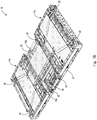
- FIG. 1A and 1B An example of an embodiment of a container according to aspects of the present invention is depicted in FIG. 1A and 1B as a collapsible container 10 having an interior for the storage and transport of produce.
- FIGs. 1A and 1B illustrated the container in an erected configuration and a collapsed configuration, respectively.
- Container 10 includes a base 13 that extends in a horizontal plane, and four walls (illustrated as two endwalls 11a, 11b, and two sidewalls 12a, 12b). At least one of the walls 12a includes an opening O (shown in FIG. 2A ) through which access to the interior of the container is allowed.
- An access door 16 covers the opening when in a closed position.
- wall 12a and the access door 16 together include a latching system to secure the access door to wall 12a and eliminate or decrease the likelihood of formation of catch points at the access door.
- a latching system may be provided with a latching sub-system in accordance with aspects of the invention on both lateral sides of the door (i.e., latching sub-system 20a and latching sub-system 20b) or can be provided with a latching sub-system in accordance with aspects of the invention on only one lateral side.
- Each latching sub-system comprises a latch and a catch.
- only one latching sub-system is illustrated and described in detail, however, it will be understood that a second latching sub-system may be provided.
- the second latching system is typically configured and operated in a same manner as the first latching system.
- the second latching sub-systems is a mirror image of the first latching system, however, it is to be understood that the sub-systems may any suitable construction, for example a construction as described herein.
- the interior of the container 10 is primarily defined by the base 13, sidewalls 12 and endwalls 11.
- a handle 15 is located near the top center of each endwall 11.
- the base 13 and endwalls 11, sidewalls 12 interior surfaces may be flat and smooth, or contoured to reduce the likelihood of bruising the contents of the container.
- the container may have various ventilation holes 14 along its walls 12a, 12b and base 13, which allow for forced air to travel to the produce while packed in the container.
- the endwalls 11 and sidewalls 12 of the container may be connected to the base 13 through the use of a plurality of hinges 22 (as shown) or other movable couplings, or may be rigidly connected to the base 13.
- Hinges 22 permit the endwalls 11 and sidewalls 12 to be folded down toward the base 13 when the container is in the "collapsed" arrangement (shown in FIG. IB), and the hinges 22 allow the endwalls 11 and sidewalls 12 to be moved to an upright position when the container is in the "erected" arrangement (shown in FIG. 1A ).
- conventional corner latching systems 24 may be used to maintain the walls in the erected arrangement.
- Container 10 is typically molded from a plastic material, for example polypropylene. Suitable plastic materials include, but are not limited to, polyethylene, polypropylene, polyvinyl chloride, polyurethane, polyester, epoxy resin, phenolic resin, polystyrene, polycarbonate, combinations thereof and the like.
- plastic is used generically herein in its conventional manner and refers to any of the above-listed materials or other similar materials now existing or later developed.
- Container 10 has a construction that is designed to be strong relative to its weight. The material of the container allows it to be rigid enough to maintain its structural form when erected for storage or transportation, thereby protecting the produce it contains. At the same time, the material of the base 13, endwalls 11, and sidewalls 12 of the container 10 are flexible enough to minimize damage to the contents of the container.
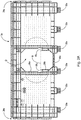
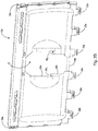
- FIGs. 2A and 2B are an exterior, plan view of wall 12a and an interior plan view of wall 12a, respectively, each shown with the wall separated from the rest of the container.
- Wall 12a includes hinge portions 22a and corner latch system portions 24a, as well as opening O having catches 28 1 , 28 2 disposed at an intermediate location M along the lateral sides of opening O.
- wall 12a includes a first hinge component 40a formed as a bar onto which a clamp 40b (shown in FIG. 4A ) of access door 16 is snapped to form an access door hinge 40.
- a door jam 26a is present around an upper portion of the opening at a location where upper portion 16a of access door 16 (shown for example in FIG. 4A ) rests against wall 12a to help prevent the door from moving into the interior of the container.
- the door jam 26a extends continuously around the upper portion of the opening, however, it may extend over a fraction of the lower portion of the opening or form discontinuous sections around opening O.
- a door jam 26b may also be present around a lower portion of opening O at a location where lower portion 16b of access door 16 (shown for example in FIG. 4A ) rests to help prevent the door from moving into the interior of the container.
- the door jam 26b extends continuously around the lower portion of the opening, however, it may extend over a fraction of the lower portion of the opening or form discontinuous sections around the opening.
- Hinge 40 operates with simple rotation about an axis (e.g., an axis in bar 40a), and lower door portion 16b does and cannot move radially away from bar 40a.
- catch 28 1 and catch 28 2 are positioned along a lateral side of opening 0, at wall intermediate location M.
- the access door includes at least one latch proximate a door intermediate location, the latch to be received in a space defined, at least in part, by catch 28 1 .
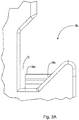
- FIGs 3A-3C are an interior plan view, an exterior plan view and a cross sectional view, respectively, showing catch 28 1 in greater detail.
- Catch 28 1 comprises an outer wall 28a.
- Catch 28 1 defines, in part, a space S into which latch 45a (shown, for example, in FIG. 6A ) is received.
- latch 45a shown, for example, in FIG. 6A
- outer wall 28a prevents the latch and the intermediate portion of the access door from moving in an outward direction.
- catch 28 1 may further comprises a side wall 28b that further defines space S. Additionally, by sloping side wall 28b, as illustrated, the inner side wall may help to center access door 16 when the latching is occurring.
- the position of wall intermediate location M is defined by the uppermost location of an outer wall of the catch, over which a latch moves to enter space S.
- an inner wall 28c may be present to prevent the latch and the intermediate portion of the wall from moving in an inward direction.
- optional jam interfaces 48a and 48b shown in FIG. 4B
- optional jams 26a and 26b shown in FIG. 2A
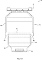
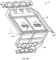
- FIG. 4A is a projection view of the outside of access door 16
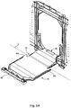
- FIG. 4B is a plan view of the inside of access door 16.
- Access door 16 comprises upper portion 16a and lower portion 16b, a second hinge component 40b that couples the bottom of door 16 to wall 12a (shown in FIG. 1A ), a second hinge 50 which couples upper portion 16a to the lower portion 16b, and a connector 42 that connects the top of access door 16 to the wall 12a, and latches 45a and 45b for coupling access door 16 to catches 28 1 and 28 1 of wall 12a (shown in FIG. 2A ), respectively.
- upper portion 16a and lower portion 16b are more rigid than the portion of the wall constituting second hinge 50.
- first hinge 40 which comprises first hinge component 40a (shown in FIG. 2A ) and second hinge component 40b) to an open position.
- the second hinge component 40b is formed as a clamp that snaps over corresponding first hinge component 40a (e.g., a bar) on wall 12a.
- the clamp rotates about the bar in a conventional manner to achieve the open and closed position.
- first hinge component 40a e.g., a bar
- any suitable rotational bearing may be used.
- the bar is formed on wall 12a it may also be formed on base 13.
- Hinge 50 is located at a door intermediate location L.
- the hinge is shown as a living hinge, the hinge may be any suitable rotational bearing configured to allow pivoting movement about intermediate location L.
- Latches 45a, 45b extend from the upper portion below door intermediate location L when door 16 is in an unflexed state.
- Location L is defined as the location of the axis about which the door and latches move when the upper portion 16a is rotated relative to lower portion 16a, and hinges 22 and 40 are maintained in a given state of rotation.
- door intermediate location L is positioned to be at or above the wall intermediate location M when the container is in an erected arrangement.
- Upper portion 16a has an upper end 16 UE where connector 42 is disposed. Connector 42 connects the upper end 16 UE to wall 12a to maintain access door 16 in the closed position.
- the lower portion 16b has a lower end 16 LE where door 16 is coupled to wall 12a by second hinge 40.
- Connector 42 can be configured as any suitable connector for maintaining door 16 in a closed position.
- connector 42 can be configured as the latching system described in co-pending United States Provisional Patent Application 62/387,285, filed December 23, 2015 and titled PRODUCE SHIPPING CONTAINER.
- Location L is disposed intermediate hinge component 40a and connector 42. Location L can be located anywhere between hinge component 40a and connector 42 (with the catches correspondingly located); however it is typically desirable that location L be located near the midpoint between hinge and connector so that the likelihood that a significant gap between wall 12a and door 16 is formed is relatively low.
- a height of access door 16 is defined as the distance between upper end 16 UE and lower end 16 LE .
- the term "midpoint" is defined herein to mean in a region that is greater than thirty percent of the access door height from upper end 16 UE and greater than thirty percent of the access door height from lower end 16 LE .
- FIGs. 4C and 4D are an exterior view and an interior view, respectively, of a portion of access door 16 showing latch 45b in greater detail.
- Latch 45b is a protrusion extending a distance D down form upper portion 16a of door 16. As indicated above, latch 45b extends for upper portion 16a below intermediate location L.
- the latch includes an outward facing concave surface CV which interfaces with a convex surface CX of catch 28 1 (shown in FIG. 3C ).
- Latch also includes an optional raised portion 46 (extending in the outward direction from surface CV) that fits into space Q (shown in FIG. 3A ) which provides lateral stability to door 16 when the door is moving to the closed position and when door 16 is in a closed, latched position.
- jam interfaces 48a and 48b may be provided to interface with jam 26a and 26b (shown in FIG. 2A ), respectively.
- the shape of one embodiment of a latch is illustrated, however, a latch can have any of a variety of shapes. In other embodiments, the latch outward-facing surface may be convex and the catch inward-facing is concave.
- FIGs. 4E and 4F are an exterior view and an interior view of access door 16 when it is flexed inwardly about second hinge 50 at intermediate location L.
- FIG. 4G is a cross sectional view of a portion of access door 16 showing further detail of the construction of living hinge 50.
- FIG. 4G shows the narrowed portion of access door 16 that constitutes the hinge. The narrowed portion permits relative rotation of upper portion 16a and lower portion 16b about intermediate location L.
- Hinge 50 is constructed and operates in a convention manner. Ribs 52a and 52b are included above and below hinge 50, respectively, to localize the flexure of the hinge.
- FIGs. 5A , 5B and 5C show door 16 in the open position, the partially closed position with the hinge flexed, and the closed position, respectively.
- door 16 is unflexed about the intermediate location L.
- FIG. 5B door 16 is flexed to allow latches 45a and 45b to be moved to a location above catches 28 1 and 28 2 (also shown in FIGs. 6A and 6B for latch 45a and catch 28 1 ).
- Access door 16 is movable about second hinge 50 from a closed position, in which the door covers opening O, to an open position in which the interior of the container can be accessed through the opening.
- Door intermediate location L is positioned to be at or above the wall intermediate location M when the container is in an erected arrangement.
- a flexed state of hinge 50
- latches 45a and 45b are moved to a location above catches 28a and 28b such that door 16 can be rotated about first hinge 40 (shown in FIGs. 5A-5C ) to a closed position.
- latches 45a and 4b are aligned with catches 28 1 and 28 2 , respectively, in the horizontal direction H so that each latch is received into a space S when door 16 is moved to the closed position.
- connector 42 can connect access door 16 to wall 12a to maintain door 16 in a closed position.
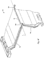
- FIGs. 6A-6D are cross-sectional views of access door 16 and wall 12a showing the latching process of latching system 20 in greater detail.
- FIG. 6A shows access door 16 flexed about the intermediate location L such that latch 45a is raised above catch 28 1 , as access door 16 is rotated toward a closed position.
- FIG. 6B shows door 16 rotated to a position where latch 45a has cleared catch 28 1 and access door 16 remains flexed about the intermediate location L.
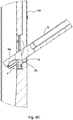
- FIG. 6C shows access door 16 as the door begins to be rotated about intermediate location L toward the unflexed state.
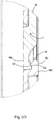
- FIG. 6D shows door 16 in the unflexed state with latch 45a exterior-facing surface CV interfacing with interior surface CX of catch 28 1 .
- step 5A - 6D door 16 is in the closed state and latch 45a is moved to its final position.
- Connector 42 (shown in FIG. 5C ) may actuated to connect access door 16 to wall 12a. Actuation of the connector may occur as a result of the access door rotating around intermediate location L to the unflexed state or additional action may be taken to connect access door 16 to wall 12a. It is to be appreciated that, for the illustrated embodiment, all of steps 5A - 6D are achieved with movement at hinge 40 that involves only rotation of lower door portion 16b (i.e., in the illustrated embodiment, lower door portion 16b is not and cannot be moved radially away from bar 40a).
Landscapes
- Engineering & Computer Science (AREA)
- Mechanical Engineering (AREA)
- Rigid Containers With Two Or More Constituent Elements (AREA)
- Packaging Of Annular Or Rod-Shaped Articles, Wearing Apparel, Cassettes, Or The Like (AREA)
- Vehicle Step Arrangements And Article Storage (AREA)
- Cartons (AREA)
- Wing Frames And Configurations (AREA)
- Details Of Rigid Or Semi-Rigid Containers (AREA)
Description
- Containers, especially containers having an access door for accessing an interior of the container.
- Bananas are harvested from trees in tropical growing regions such as Central and South America. Bananas to be exported are picked green, shipped to distribution centers in consuming regions, and delivered to retail stores in a state of ripeness appropriate for retail sale. Conventionally, growers pack bananas in covered, corrugated cardboard boxes containing about 40 pounds of bananas per box.
- The industry-standard method for packaging bananas for shipment to North American retailers has been to pack in corrugated cardboard boxes that have been tailored to this application. Corrugated boxes for bananas are of a 2-piece construction with outside dimensions of about 19.7" (50 cm) in length x 15.75" (40 cm) in width x 9.69" (24.6 cm) in height. The 2-piece boxes include a bottom and a top cover that telescopes the full height of the bottom to contribute to stacking strength due to the resultant double-wall construction. Corrugated boxes weigh approximately 3 lbs. each.
- Filled boxes are placed on pallets in eight layers, each layer including 5 or 6 boxes. Bananas are refrigerated to between 13.5° and 15° C (56.3 and 59.0° F) during transport to suspend the ripening process ("put the bananas to sleep"). This allows bananas to reach grocery stores without being overripe.
- Pallets of cooled ("sleeping") bananas are loaded onto ships for transport from growing regions to consuming regions. Temperature continues to be controlled throughout shipment to distribution centers in the consuming regions. Acceptance testing usually occurs at a distribution center. Upon arrival, bananas on a given pallet are inspected to determine if the shipment will be accepted or rejected. A typical inspection involves sampling bananas in 3-4 boxes on each pallet. The bananas are selected at different layers and sides of the 30-48 box arrangement to determine the quality of bananas and their state of ripeness. When shipping in corrugated boxes, a hole is cut in the selected boxes with a knife. One or more bananas are removed through the hole and inspected. Attributes tested include physical appearance, size, sweetness, and temperature.
- Accepted pallets of bananas are moved to a ripening room. There the temperature of the bananas is raised and the bananas are exposed to ethylene gas to restart the ripening process ("waken the bananas"). The ripening process continues in the ripening room for about 3-5 days. After sufficient ripening, the pallets are loaded onto trucks at the distribution center for delivery to retail stores. Bananas are inspected during the ripening process in a manner similar to inspection during acceptance so that ripening conditions can be adjusted if needed.
- The current transport process for bananas has several disadvantages. During the inspection process, the cutting of containers may result in direct damage to the bananas from the cutting implement as a container is cut, and indirect damage to the bananas may result from structural weakness caused by the cutting of the boxes, which may result in the crushing of bananas during transportation.
- Plastic containers have been produced that are designed to replace cardboard boxes for shipping bananas, although they have achieved only limited commercial success. Plastic containers have included re-closable access doors with a hinge at a bottom end and a latch at the top end; however, they have been relatively heavy and had stiff construction. Stiff RPCs with 4 walls and a base are designed to handle stacking loads transferred through the walls and base of containers to the pallet with a safety margin to achieve many years of life. The stiff nature of the RPC has exacerbated packing damage associated with transporting the requisite quantity of bananas.
- One proposed plastic container, described in published
PCT Application WO2015134067 , has a light weight construction giving the box a relatively high flexibility that is similar to corrugated cardboard boxes. One of the side walls comprises a door-provided access opening; the door being coupled to the wall by a hinge at the lower end and movable about the hinge from a closed position, in which the upper end of the door can be connected to the wall, to an open position in which the interior of the container can be accessed through the opening. - To achieve the reduced weight, the thicknesses of walls have been reduced, and rigidizing features such as ribs in the walls have been reduced in number and in thickness, and positioned to result in increased flexibility of the walls.
- While such design choices address concerns such as container weight and damage to fruit, they present challenges in maintaining sufficient integrity of the erected boxes.
- In a flexible plastic container, one particular challenge occurs as a result of the access door flexing excessively due to the internal pressure from the fruit (e.g., bananas), which results in the edges of the door separating (in an outward direction) from the wall from which it is to contact. The separation results in catch points which, when the containers are stacked and de-stacked, and as the pallets full of containers are moved relative to one another in a warehouse or shipping vessel, results in pallets and containers contacting the catch points and damaging the door and/or at least partially tearing the door from the container. Use of conventional latches proximate the middle of the lateral edges of the access door of a thinned, flexible container was found unworkable due to the limited space available for the latch; such latches extended excessively into the interior of the container where contents may be damaged, or extending from the exterior of the container resulting in catch points.
- An aspect of the invention is directed to a container having an interior to hold produce, comprising a base and four walls. The four walls, in combination with the base, define the interior. Each of the walls is coupled to the base. At least one of the walls has an opening allowing access to the interior. The one of the walls has an at least one catch positioned at a wall intermediate location along a lateral side of the opening. A door having a rigid upper portion and a rigid lower portion. The lower portion is coupled to the upper portion by a first hinge at a door intermediate location. The door intermediate location is positioned at or above the wall intermediate location when the container is in an erected arrangement. The upper portion has an upper end and the lower portion having a lower end. The door is coupled to the one of the walls by a hinge at the lower end. The door is movable about the hinge from a closed position in which the door covers the opening to an open position in which the interior can be accessed through the opening. The door has at least one rigid latch extending from the upper portion to a location below the door intermediate location when the door is in an unflexed state and the at least one rigid latch is aligned with the at least one catch so as to be received in a space defined by the catch. An interior surface of the catch faces an exterior-facing surface of the latch when the door is moved to the closed position. The door has a connector to connect the upper end to the one of the walls to maintain the closed position. The hinge may be a living hinge.
- In some embodiments, the container further comprises a second catch along a second lateral side of the opening that is opposite the lateral side on which the first latch is disposed. The second rigid latch extends from the upper portion to a location below the door intermediate location when the door is in an unflexed state and the second latch is aligned with the second catch so as to be received in a second space defined by the second catch. An interior surface of the second catch faces an exterior-facing surface of the second latch when the door is moved to the closed position. In some embodiments, the door intermediate location is disposed at a midpoint of the door.
- In some embodiments, the four walls comprise two opposing sidewalls and two opposing endwalls. In such embodiments, the opening may be disposed in a sidewall.
- In some embodiments, each of the walls is attached to the base by a corresponding at least one rotatable bearing. In some embodiments, the at least one of the walls comprises a jam extending around at least a portion of the opening, and the door rests against the jam when the door is in a closed position.
- In some embodiments, the interior-facing surface is disposed on an outer wall of the catch the outer wall defining a space into which the latch is received, and the catch further comprises at least one of a side wall and an inner wall to further define the space.
- In some embodiments, the interior surface of the catch has a convex shape and the exterior-facing surface of the latch has a concave shape, the exterior-facing surface of the latch being interfaced with the interior surface of the catch.
- The term "rigid" as used herein refers to an object that is able to support itself against gravity in all orientations. It will be appreciated that a rigid object may some flexibility. A portion of an object that cannot support itself against gravity (e.g., a hinge) is not rigid.
- The term "latch" is defined herein to mean a protrusion.
- The term "catch" is defined herein to mean a mechanical feature including at least one protrusion defining, at least in part, a space into which a latch is received, and after receipt of the latch into the space, the at least one protrusion limiting the movement of the latch in at least one direction.
- The term "protrusion" is defined herein to mean a feature that projects outward from its immediate surrounding.
- The nature and mode of operation of the present invention will now be more fully described in the following detailed description of the invention taken with the accompanying drawing figures, in which:
-
FIGs. 1A and1B illustrate an example of an embodiment of a container according to aspects of the present invention in an erected configuration and a collapsed configuration, respectively; -
FIGs. 2A and2B are an exterior plan view and an interior plan view of a sidewall of the container ofFIG. 1A ; -
FIGs. 3A-3C are an interior plan view, an exterior plan view and a cross sectional, side view taken atline 3C - 3C ofFIG. 3B , respectively, showing further detail of a catch of the wall; -
FIG. 3D is a cross sectional view of an alternative embodiment of a catch; -
FIGs. 4A and4B are a projection view of the outside of access door of the container ofFIG. 1A , and a plan view of the inside of access door of the container ofFIG. 1A , respectively; -
FIGs. 4C and4D are an exterior view and an interior view of a portion access door ofFIG. 1A showing the latch in greater detail; -
FIGs. 4E and4F are an exterior view and an interior view of the access door ofFIG. 4A when the access door is flexed inwardly at a living hinge located at an intermediate location; -
FIG. 4G is a cross sectional view of a portion of the access door ofFIG. 4A showing further details of the construction of the living hinge; -
FIGs. 5A ,5B and5C show the access door in an open state, a partially closed state with the hinge flexed, and closed state, respectively; and -
FIGs. 6A-6D are cross sections of the access door and the wall ofFIG. 5A-5C showing the latching process in greater detail. - An example of an embodiment of a container according to aspects of the present invention is depicted in
FIG. 1A and1B as acollapsible container 10 having an interior for the storage and transport of produce.FIGs. 1A and1B illustrated the container in an erected configuration and a collapsed configuration, respectively.Container 10 includes a base 13 that extends in a horizontal plane, and four walls (illustrated as twoendwalls sidewalls walls 12a includes an opening O (shown inFIG. 2A ) through which access to the interior of the container is allowed. Anaccess door 16 covers the opening when in a closed position. As described in greater detail below,wall 12a and theaccess door 16 together include a latching system to secure the access door towall 12a and eliminate or decrease the likelihood of formation of catch points at the access door. - A latching system may be provided with a latching sub-system in accordance with aspects of the invention on both lateral sides of the door (i.e., latching
sub-system 20a and latching sub-system 20b) or can be provided with a latching sub-system in accordance with aspects of the invention on only one lateral side. Each latching sub-system comprises a latch and a catch. In the discussion below, only one latching sub-system is illustrated and described in detail, however, it will be understood that a second latching sub-system may be provided. The second latching system is typically configured and operated in a same manner as the first latching system. Typically, the second latching sub-systems is a mirror image of the first latching system, however, it is to be understood that the sub-systems may any suitable construction, for example a construction as described herein. - The interior of the
container 10 is primarily defined by thebase 13, sidewalls 12 andendwalls 11. Ahandle 15 is located near the top center of eachendwall 11. Thebase 13 and endwalls 11, sidewalls 12 interior surfaces may be flat and smooth, or contoured to reduce the likelihood of bruising the contents of the container. Because the container is designed to hold produce that may be purposely ripened while in the interior of the container, the container may havevarious ventilation holes 14 along itswalls base 13, which allow for forced air to travel to the produce while packed in the container. - The
endwalls 11 and sidewalls 12 of the container may be connected to the base 13 through the use of a plurality of hinges 22 (as shown) or other movable couplings, or may be rigidly connected to thebase 13.Hinges 22 permit the endwalls 11 and sidewalls 12 to be folded down toward the base 13 when the container is in the "collapsed" arrangement (shown in FIG. IB), and thehinges 22 allow the endwalls 11 and sidewalls 12 to be moved to an upright position when the container is in the "erected" arrangement (shown inFIG. 1A ). In embodiments including hinged walls, conventionalcorner latching systems 24 may be used to maintain the walls in the erected arrangement. -
Container 10 is typically molded from a plastic material, for example polypropylene. Suitable plastic materials include, but are not limited to, polyethylene, polypropylene, polyvinyl chloride, polyurethane, polyester, epoxy resin, phenolic resin, polystyrene, polycarbonate, combinations thereof and the like. The term "plastic" is used generically herein in its conventional manner and refers to any of the above-listed materials or other similar materials now existing or later developed.Container 10 has a construction that is designed to be strong relative to its weight. The material of the container allows it to be rigid enough to maintain its structural form when erected for storage or transportation, thereby protecting the produce it contains. At the same time, the material of thebase 13, endwalls 11, and sidewalls 12 of thecontainer 10 are flexible enough to minimize damage to the contents of the container. -
FIGs. 2A and2B are an exterior, plan view ofwall 12a and an interior plan view ofwall 12a, respectively, each shown with the wall separated from the rest of the container.Wall 12a includeshinge portions 22a and cornerlatch system portions 24a, as well as opening O having catches 281, 282 disposed at an intermediate location M along the lateral sides of opening O. In the illustrated embodiment,wall 12a includes afirst hinge component 40a formed as a bar onto which aclamp 40b (shown inFIG. 4A ) ofaccess door 16 is snapped to form anaccess door hinge 40. - In some embodiments, as shown, a
door jam 26a is present around an upper portion of the opening at a location whereupper portion 16a of access door 16 (shown for example inFIG. 4A ) rests againstwall 12a to help prevent the door from moving into the interior of the container. In some embodiments thedoor jam 26a extends continuously around the upper portion of the opening, however, it may extend over a fraction of the lower portion of the opening or form discontinuous sections around opening O.A door jam 26b may also be present around a lower portion of opening O at a location wherelower portion 16b of access door 16 (shown for example inFIG. 4A ) rests to help prevent the door from moving into the interior of the container. In some embodiments, thedoor jam 26b extends continuously around the lower portion of the opening, however, it may extend over a fraction of the lower portion of the opening or form discontinuous sections around the opening.Hinge 40 operates with simple rotation about an axis (e.g., an axis inbar 40a), andlower door portion 16b does and cannot move radially away frombar 40a. - In the illustrated embodiment, catch 281 and catch 282 (shown in greater detail in
FIGs. 3A - 3C ) are positioned along a lateral side ofopening 0, at wall intermediate location M. As described in greater detail below, the access door includes at least one latch proximate a door intermediate location, the latch to be received in a space defined, at least in part, by catch 281. -
FIGs 3A-3C are an interior plan view, an exterior plan view and a cross sectional view, respectively, showing catch 281 in greater detail. Catch 281 comprises anouter wall 28a. Catch 281 defines, in part, a space S into whichlatch 45a (shown, for example, inFIG. 6A ) is received. When access door 16 (shown inFIG. 1A ) is in a closed position and the latch is properly located on the inside ofouter wall 28a,outer wall 28a prevents the latch and the intermediate portion of the access door from moving in an outward direction. - One or more additional walls (i.e., in addition to
outer wall 28a) may be included in a catch to further define space S and limit latch movement in more directions than outward. For example, catch 281 may further comprises aside wall 28b that further defines space S. Additionally, by slopingside wall 28b, as illustrated, the inner side wall may help to centeraccess door 16 when the latching is occurring. The position of wall intermediate location M is defined by the uppermost location of an outer wall of the catch, over which a latch moves to enter space S. - As shown in the embodiment illustrated in
FIG. 3D , in some embodiments, aninner wall 28c may be present to prevent the latch and the intermediate portion of the wall from moving in an inward direction. In the embodiment illustrated inFIGs. 2A-2B ,optional jam interfaces FIG. 4B ) in combination withoptional jams FIG. 2A ) to limit inward and outward movement ofaccess door 16. -
FIG. 4A is a projection view of the outside ofaccess door 16, andFIG. 4B is a plan view of the inside ofaccess door 16.Access door 16 comprisesupper portion 16a andlower portion 16b, asecond hinge component 40b that couples the bottom ofdoor 16 towall 12a (shown inFIG. 1A ), asecond hinge 50 which couplesupper portion 16a to thelower portion 16b, and aconnector 42 that connects the top ofaccess door 16 to thewall 12a, and latches 45a and 45b forcoupling access door 16 to catches 281 and 281 ofwall 12a (shown inFIG. 2A ), respectively. It will be appreciated thatupper portion 16a andlower portion 16b are more rigid than the portion of the wall constitutingsecond hinge 50. - As described in greater detail below with reference to
FIGs. 5A-5C ,access door 16 is movable about a first hinge 40 (which comprisesfirst hinge component 40a (shown inFIG. 2A ) andsecond hinge component 40b) to an open position. In the illustrated embodiment, thesecond hinge component 40b is formed as a clamp that snaps over correspondingfirst hinge component 40a (e.g., a bar) onwall 12a. The clamp rotates about the bar in a conventional manner to achieve the open and closed position. It is to be appreciated that although a particular embodiment of a hinge is illustrated, any suitable rotational bearing may be used. Additionally, although the bar is formed onwall 12a it may also be formed onbase 13. -
Hinge 50 is located at a door intermediate location L. Although the hinge is shown as a living hinge, the hinge may be any suitable rotational bearing configured to allow pivoting movement about intermediatelocation L. Latches door 16 is in an unflexed state. Location L is defined as the location of the axis about which the door and latches move when theupper portion 16a is rotated relative tolower portion 16a, and hinges 22 and 40 are maintained in a given state of rotation. As discussed in greater detail below, door intermediate location L is positioned to be at or above the wall intermediate location M when the container is in an erected arrangement.Upper portion 16a has anupper end 16UE whereconnector 42 is disposed.Connector 42 connects theupper end 16UE towall 12a to maintainaccess door 16 in the closed position. Thelower portion 16b has alower end 16LE wheredoor 16 is coupled towall 12a bysecond hinge 40. -
Connector 42 can be configured as any suitable connector for maintainingdoor 16 in a closed position. For example,connector 42 can be configured as the latching system described in co-pendingUnited States Provisional Patent Application 62/387,285, filed December 23, 2015 - Location L is disposed
intermediate hinge component 40a andconnector 42. Location L can be located anywhere betweenhinge component 40a and connector 42 (with the catches correspondingly located); however it is typically desirable that location L be located near the midpoint between hinge and connector so that the likelihood that a significant gap betweenwall 12a anddoor 16 is formed is relatively low. A height ofaccess door 16 is defined as the distance betweenupper end 16UE andlower end 16LE. The term "midpoint" is defined herein to mean in a region that is greater than thirty percent of the access door height fromupper end 16UE and greater than thirty percent of the access door height fromlower end 16LE. -
FIGs. 4C and4D are an exterior view and an interior view, respectively, of a portion ofaccess door 16 showinglatch 45b in greater detail.Latch 45b is a protrusion extending a distance D down formupper portion 16a ofdoor 16. As indicated above,latch 45b extends forupper portion 16a below intermediate location L. - In the illustrated embodiment, the latch includes an outward facing concave surface CV which interfaces with a convex surface CX of catch 281 (shown in
FIG. 3C ). Latch also includes an optional raised portion 46 (extending in the outward direction from surface CV) that fits into space Q (shown inFIG. 3A ) which provides lateral stability todoor 16 when the door is moving to the closed position and whendoor 16 is in a closed, latched position. As described above,jam interfaces jam FIG. 2A ), respectively. The shape of one embodiment of a latch is illustrated, however, a latch can have any of a variety of shapes. In other embodiments, the latch outward-facing surface may be convex and the catch inward-facing is concave. -
FIGs. 4E and4F are an exterior view and an interior view ofaccess door 16 when it is flexed inwardly aboutsecond hinge 50 at intermediate location L.FIG. 4G is a cross sectional view of a portion ofaccess door 16 showing further detail of the construction of livinghinge 50.FIG. 4G shows the narrowed portion ofaccess door 16 that constitutes the hinge. The narrowed portion permits relative rotation ofupper portion 16a andlower portion 16b about intermediatelocation L. Hinge 50 is constructed and operates in a convention manner.Ribs hinge 50, respectively, to localize the flexure of the hinge. -
FIGs. 5A ,5B and5C showdoor 16 in the open position, the partially closed position with the hinge flexed, and the closed position, respectively. In bothFIGs. 5A and5C ,door 16 is unflexed about the intermediate location L. InFIG. 5B ,door 16 is flexed to allowlatches FIGs. 6A and6B forlatch 45a and catch 281).Access door 16 is movable aboutsecond hinge 50 from a closed position, in which the door covers opening O, to an open position in which the interior of the container can be accessed through the opening. - Door intermediate location L is positioned to be at or above the wall intermediate location M when the container is in an erected arrangement. As shown in greater detail below in
FIGs. 6A and6B , asdoor 16 is rotated abouthinge 40 toward a closed state, such a configuration allows a flexed state (of hinge 50) to be attained, where latches 45a and 45b are moved to a location abovecatches door 16 can be rotated about first hinge 40 (shown inFIGs. 5A-5C ) to a closed position. It will be appreciated that latches 45a and 4b are aligned with catches 281 and 282, respectively, in the horizontal direction H so that each latch is received into a space S whendoor 16 is moved to the closed position. Whendoor 16 is in the closed position,connector 42 can connectaccess door 16 towall 12a to maintaindoor 16 in a closed position. -
FIGs. 6A-6D are cross-sectional views ofaccess door 16 andwall 12a showing the latching process of latchingsystem 20 in greater detail.FIG. 6A showsaccess door 16 flexed about the intermediate location L such thatlatch 45a is raised above catch 281, asaccess door 16 is rotated toward a closed position.FIG. 6B showsdoor 16 rotated to a position wherelatch 45a has cleared catch 281 andaccess door 16 remains flexed about the intermediate location L.FIG. 6C showsaccess door 16 as the door begins to be rotated about intermediate location L toward the unflexed state.FIG. 6D showsdoor 16 in the unflexed state withlatch 45a exterior-facing surface CV interfacing with interior surface CX of catch 281. When in the state illustrated inFIG. 6D ,door 16 is in the closed state andlatch 45a is moved to its final position. Connector 42 (shown inFIG. 5C ) may actuated to connectaccess door 16 towall 12a. Actuation of the connector may occur as a result of the access door rotating around intermediate location L to the unflexed state or additional action may be taken to connectaccess door 16 towall 12a. It is to be appreciated that, for the illustrated embodiment, all of steps 5A - 6D are achieved with movement athinge 40 that involves only rotation oflower door portion 16b (i.e., in the illustrated embodiment,lower door portion 16b is not and cannot be moved radially away frombar 40a). - Modifications and changes to aspects of the invention described above should be readily apparent to those having ordinary skill in the art, which modifications are intended to be within the scope of the invention as claimed. It also is understood that the foregoing description is illustrative of the present invention and should not be considered as limiting. Therefore, other embodiments of the present invention are possible. The scope of the present invention is defined by the following claims.
Claims (10)
- A container (10) having an interior to hold produce, comprising:A) a base (13);B) four walls (11a, lib, 12a, 12b), which in combination with the base (13) define the interior, each of the walls (11a, 11b, 12a, 12b) being coupled to the base (13), at least one of the walls (12a) having an opening (O) allowing access to the interior, the one of the walls (12a) having an at least one catch (281, 282) positioned at a wall intermediate location (M) along a lateral side of the opening (O);C) a door (16) i) the door (16) having a rigid upper portion (16a) and a rigid lower portion (16b) coupled to the upper portion (16a) by a first hinge (50) at a door intermediate location (L), the door intermediate location (L) being positioned at or above the wall intermediate location (M) when the container (10) is in an erected arrangement, the upper portion (16a) having an upper end and the lower portion (16b) having a lower end, ii) the door (16) being coupled to the one of the walls (12a) by a hinge (40b) at the lower end, the door (16) movable about the hinge (40b) at the lower end of the door (16) from a closed position in which the door (16) covers the opening (O) to an open position in which the interior can be accessed through the opening (O), iii) the door (16) having at least one rigid latch (45a, 45b) extending from the upper portion (16a) to a location below the door intermediate location (L) when the door (16) is in an unflexed state and the at least one rigid latch (45a, 45b) aligned with the at least one catch (281, 282) so as to be received in a space defined by the catch (281, 282) with an interior surface of the catch (281, 282) facing an exterior-facing surface of the latch (45a, 45b) when the door (16) is moved to the closed position, and iv) the door (16) having a connector (42) to connect the upper end to the one of the walls (12a) to maintain the closed position.
- The container (10) of claim 1, further comprising a second catch (282) along a second lateral side of the opening (O) that is opposite the lateral side on which the first latch is disposed, and a second rigid latch (45b) extending from the upper portion (16a) to a location below the door intermediate location (L) when the door (16) is in the unflexed state and the second latch (45b) aligned with the second catch (282) so as to be received in a second space defined by the second catch (282) with an interior surface of the second catch (282) facing an exterior-facing surface of the second latch (45b) when the door (16) is moved to the closed position.
- The container (10) of claim 1, wherein the door intermediate location (L) is disposed at a midpoint of the door (16).
- The container (10) of claim 1, wherein the four walls (11a, 11b, 12a, 12b) comprise two opposing sidewalls (12a, 12b) and two opposing endwalls (11a, 11b).
- The container (10) of claim 4, wherein the opening (O) is disposed in a sidewall (12a).
- The container (10) of claim 1, wherein each of the walls (11a, 11b, 12a, 12b) is attached to the base (13) by a corresponding at least one rotatable bearing.
- The container (10) of claim 1, wherein the at least one of the walls (12a) comprises a jam extending around at least a portion of the opening (O), and the door (16) rests against the jam when the door (16) is in the closed position.
- The container (10) of claim 1, wherein the interior-facing surface is disposed on an outer wall of the catch (281, 282), the outer wall defining the space into which the latch (45a, 45b) is received, and the catch (281, 282) further comprises at least one of a side wall and an inner wall to further define the space.
- The container (10) of claim 1, wherein the interior surface of the catch (281, 282) has one of a convex shape and a concave shape, and the exterior-facing surface of the latch (45a, 45b) has the other of the convex shape and the concave shape, the exterior-facing surface of the latch (45a, 45b) being interfaced with the interior surface of the catch (281, 282).
- The container (10) of claim 1, wherein the first hinge (50) is a living hinge.
Applications Claiming Priority (2)
| Application Number | Priority Date | Filing Date | Title |
|---|---|---|---|
| US15/266,652 US10118727B2 (en) | 2016-09-15 | 2016-09-15 | Container having an access door latching system |
| PCT/US2017/051532 WO2018053107A1 (en) | 2016-09-15 | 2017-09-14 | Container having an access door latching system |
Publications (3)
| Publication Number | Publication Date |
|---|---|
| EP3512326A1 EP3512326A1 (en) | 2019-07-24 |
| EP3512326A4 EP3512326A4 (en) | 2020-03-11 |
| EP3512326B1 true EP3512326B1 (en) | 2021-08-25 |
Family
ID=61559487
Family Applications (1)
| Application Number | Title | Priority Date | Filing Date |
|---|---|---|---|
| EP17851512.8A Active EP3512326B1 (en) | 2016-09-15 | 2017-09-14 | Container having an access door latching system |
Country Status (11)
| Country | Link |
|---|---|
| US (1) | US10118727B2 (en) |
| EP (1) | EP3512326B1 (en) |
| CA (1) | CA3033371A1 (en) |
| CO (1) | CO2019001424A2 (en) |
| CR (1) | CR20190089A (en) |
| DO (1) | DOP2019000049A (en) |
| EC (1) | ECSP19026777A (en) |
| ES (1) | ES2895645T3 (en) |
| MX (1) | MX2019001889A (en) |
| PH (1) | PH12019500246B1 (en) |
| WO (1) | WO2018053107A1 (en) |
Families Citing this family (6)
| Publication number | Priority date | Publication date | Assignee | Title |
|---|---|---|---|---|
| WO2017112840A1 (en) * | 2015-12-23 | 2017-06-29 | Arena Packaging, Llc | Produce shipping container |
| US12448172B2 (en) * | 2018-03-05 | 2025-10-21 | Rehrig Pacific Company | Collapsible container |
| US20210323728A1 (en) * | 2020-04-21 | 2021-10-21 | Orbis Corporation | Bread tray merchandiser barrier |
| USD1004970S1 (en) * | 2021-06-14 | 2023-11-21 | Monoflo International, Inc. | Container |
| US11834258B2 (en) * | 2021-09-03 | 2023-12-05 | A. R. Arena Products, Inc. | Intermediate bulk container systems and methods of using same |
| USD1035279S1 (en) * | 2021-12-22 | 2024-07-16 | Shell Packaging Corporation | Container handle |
Family Cites Families (81)
| Publication number | Priority date | Publication date | Assignee | Title |
|---|---|---|---|---|
| US3544146A (en) | 1968-10-07 | 1970-12-01 | Shell Oil Co | Container |
| US3878980A (en) | 1971-10-29 | 1975-04-22 | Walton B Crane | Plastic reinforced produce container |
| US3797870A (en) | 1972-04-21 | 1974-03-19 | Keystone Consolidated Ind Inc | Flush mounted handle, latch bolt, lock and housing assembly |
| US3935990A (en) | 1972-11-20 | 1976-02-03 | A & E Plastik Pak Co., Inc. | Plastic reinforced produce container |
| US3935991A (en) | 1972-11-20 | 1976-02-03 | A & E Plastik Pak Co., Inc. | Plastic reinforced produce container |
| US3888525A (en) | 1974-02-06 | 1975-06-10 | William L Kousens | Hidden drawer and door latch |
| US4284299A (en) | 1979-01-22 | 1981-08-18 | Kelly Donald V | Integral handle stop and latch member for sliding screen closures |
| US4192430A (en) | 1979-03-12 | 1980-03-11 | Allibert Exploitation, Societe Anonyme | Laterally openable storage and transport box |
| US4492396A (en) | 1981-10-28 | 1985-01-08 | Siemens-Allis, Inc. | One-piece, slam-type latch for snap-in installation |
| US5275302A (en) | 1982-06-18 | 1994-01-04 | Uitz Mark O | Plastic container and pallet system |
| EP0227650B1 (en) | 1985-06-14 | 1991-09-18 | JASON, Donald M. | Resilient latching device |
| US4917413A (en) | 1985-08-08 | 1990-04-17 | Donald M. Jason | Resilient latching device |
| US4817799A (en) | 1986-10-06 | 1989-04-04 | Empak, Inc. | Disk package |
| US5121952A (en) | 1988-07-20 | 1992-06-16 | Elastolatch, Inc. | Slam latch |
| US5161709A (en) | 1989-01-30 | 1992-11-10 | World Container Corporation | Hinged collapsible container |
| US4917255A (en) | 1989-02-24 | 1990-04-17 | J.I.T. Corporation | Collapsible container |
| US4967927A (en) | 1989-03-15 | 1990-11-06 | Xytec, Inc. | Container with latchable hinged sidewall gate |
| US5199592A (en) | 1989-03-15 | 1993-04-06 | Perstorp Extec, Inc. | Container with latchable hinged sidewall gate |
| CA2045657A1 (en) | 1989-11-29 | 1991-05-30 | Ladislav S. Karpisek | Container discharge side door |
| GB9106666D0 (en) | 1991-03-28 | 1991-05-15 | Billingham Paul R | File box closure catch |
| DE4113438C2 (en) | 1991-04-25 | 1993-12-16 | Roland Streich | Collapsible cargo container or container |
| US5100015A (en) | 1991-07-05 | 1992-03-31 | Electro-Wire Products, Inc. | Latch unit for container and mating lid |
| US5583612A (en) | 1994-07-14 | 1996-12-10 | Xerox Corporation | Flexible latch with relaxed engagement |
| US5474197A (en) | 1993-12-27 | 1995-12-12 | Perstorp Xytec | Collapsible container with reduced deflection |
| US5617711A (en) | 1995-09-27 | 1997-04-08 | Chiquita Brands, Inc. | Method of producing a container of bananas and method of transferring bananas |
| US5755350A (en) | 1996-06-21 | 1998-05-26 | Acco Brands, Inc. | Storage container assembly having single-finger-actuatable door latch mechanism |
| WO1998024151A1 (en) | 1996-11-29 | 1998-06-04 | The Whitaker Corporation | Resilient latch for an electrical connector |
| US5727711A (en) | 1996-12-03 | 1998-03-17 | Her Majesty In Right Of Canada, As Represented By The Minister Of Agriculture And Agri-Food Canada | Reusable containers for the preservation of fresh fruits and vegetables |
| US6036049A (en) | 1997-04-17 | 2000-03-14 | Rehrig Pacific Company | Reusable produce crate |
| US6203077B1 (en) | 1997-10-03 | 2001-03-20 | Southco, Inc. | Over-center toggle latch with integral safety switch |
| US6220637B1 (en) | 1999-04-26 | 2001-04-24 | Motorola, Inc. | Snap fastener and interlocking tab |
| CA2273556A1 (en) | 1999-05-31 | 2000-11-30 | Thomas Gabriel Bela Merey | Foldable container |
| US6373690B1 (en) | 1999-10-21 | 2002-04-16 | Dell Usa, L.P. | Apparatus for mounting a panel to a chassis of a computer |
| US6601724B1 (en) | 1999-11-20 | 2003-08-05 | Rehrig Pacific Company | Collapsible merchandizing container |
| US6293418B1 (en) | 1999-12-09 | 2001-09-25 | Norseman Plastics Limited | Collapsible container |
| US6776300B2 (en) | 2000-04-07 | 2004-08-17 | Xytec Systems, Inc. | Collapsible container with closed, multi-paneled sidewalls |
| DE10054334C2 (en) | 2000-11-02 | 2003-04-24 | Raymond A & Cie | Retaining spring for the detachable connection of two components |
| US6595605B1 (en) | 2000-11-14 | 2003-07-22 | International Business Machines Corporation | Spring loaded latching for system enclosure panels |
| CA2365158C (en) | 2001-01-17 | 2007-05-01 | Sanko Co., Ltd. | Folding container |
| US6712404B2 (en) | 2001-05-29 | 2004-03-30 | Preferred Engineering Products Ltd. | Simplified integral inside and outside handle and operator for a latch member for closures |
| US6863175B2 (en) | 2001-07-18 | 2005-03-08 | Meadwestvaco Corporation | Locking container |
| US8109402B2 (en) | 2001-10-04 | 2012-02-07 | Schoeller Arca Systems Ab | Collapsible container for transport and storage |
| US6874679B2 (en) | 2001-10-12 | 2005-04-05 | Innovative Packaging Designs, L.P. | Container having sliding corner support |
| AUPR905301A0 (en) | 2001-11-23 | 2001-12-20 | Stichting Nijsa Holdings | Support structure |
| US7331480B1 (en) | 2002-09-27 | 2008-02-19 | Roger Nolan | Articulated hinge apparatus and related methods |
| TW578955U (en) | 2002-10-18 | 2004-03-01 | Hon Hai Prec Ind Co Ltd | Mounting apparatus for expansion card |
| DE502004000264D1 (en) | 2003-04-09 | 2006-04-13 | Georg Utz Holding Ag Bremgarte | Stackable transport box |
| US6868979B2 (en) | 2003-05-08 | 2005-03-22 | Monoflo International, Inc. | Collapsible plastic container with locking feature |
| DE202005016115U1 (en) | 2004-11-16 | 2006-04-06 | Fritz Schäfer GmbH | Storage, transport, stacking and picking containers |
| US7273203B2 (en) | 2005-02-23 | 2007-09-25 | Carnevali Jeffrey D | Locking device support |
| US7484634B2 (en) | 2005-05-17 | 2009-02-03 | Rehrig Pacific Company | Container with collapsible wall |
| WO2006132613A1 (en) | 2005-06-03 | 2006-12-14 | Linpac Materials Handling | Container assembly and latch apparatus, and related methods |
| US20070084864A1 (en) | 2005-10-14 | 2007-04-19 | The Parallax Group International, Llc | Collapsible container |
| DE102006005873B4 (en) | 2006-02-06 | 2017-05-11 | Söhner Kunststofftechnik GmbH | Wall surface part and transport container |
| US20070278223A1 (en) | 2006-06-05 | 2007-12-06 | Paul Ficker | Locking collapsible container |
| US9278775B2 (en) * | 2006-12-13 | 2016-03-08 | Rehrig Pacific Company | Crate with collapsible wall |
| US8727165B2 (en) | 2007-08-15 | 2014-05-20 | Orbis Corporation | Hinge system for a modular bulk container |
| CA2639156A1 (en) | 2007-08-28 | 2009-02-28 | Rehrig Pacific Company | Crate with collapsible wall |
| IL186787A0 (en) | 2007-10-18 | 2008-02-09 | Polymer Logistics Ltd | Foldable crate with bidirectional manually releasable latch mechanism |
| US7896184B2 (en) | 2007-11-26 | 2011-03-01 | Rehrig Pacific Company | Crate with collapsible wall |
| TWM341387U (en) | 2008-02-15 | 2008-09-21 | Wistron Corp | Fixation socket and assembly of the same and electronic device |
| US8944266B2 (en) | 2008-09-23 | 2015-02-03 | Dirtt Environmental Solutions Ltd. | Floor-mount service container and lid |
| CH699872A2 (en) | 2008-11-06 | 2010-05-14 | Utz Georg Holding Ag | Transport and storage containers. |
| US8631956B2 (en) | 2008-12-17 | 2014-01-21 | Fred Dowd | Reusable, combined multi-part product shipping box and display tray |
| DE102009049185A1 (en) | 2009-04-15 | 2011-01-05 | Ifco Systems Gmbh | Crate with foldable side walls with stable sidewall structure |
| DE102009049186A1 (en) | 2009-04-15 | 2010-11-04 | Ifco Systems Gmbh | Crate with foldable and self-locking side walls |
| DE102009049103A1 (en) | 2009-04-15 | 2010-11-04 | Ifco Systems Gmbh | Crate with foldable and removable outer walls |
| DE102009049184A1 (en) | 2009-04-15 | 2010-11-04 | Ifco Systems Gmbh | Crate with foldable side walls and locking mechanisms with overload protection |
| US8413831B2 (en) | 2009-12-16 | 2013-04-09 | Orbis Corporation | Collapsible bin |
| US8469224B2 (en) | 2010-03-30 | 2013-06-25 | Ifco Systems Gmbh | Crate |
| ES2511365T3 (en) | 2010-03-30 | 2014-10-22 | Ifco Systems Gmbh | Box |
| US20110240657A1 (en) | 2010-03-30 | 2011-10-06 | Ifco Systems Gmbh | Crate |
| US8950613B2 (en) | 2011-02-16 | 2015-02-10 | Orbis Corporation | Bulk bin container with removable side wall |
| US20130146602A1 (en) * | 2011-12-08 | 2013-06-13 | Ipl, Inc. | Hybrid container |
| US8757412B2 (en) | 2012-01-09 | 2014-06-24 | Monoflo International, Inc. | Foldable container with access opening |
| EP2620380A1 (en) | 2012-01-27 | 2013-07-31 | Rehrig Pacific Company | Collapsible container with door |
| US8915397B2 (en) | 2012-11-01 | 2014-12-23 | Orbis Corporation | Bulk container with center support between drop door and side wall |
| WO2014176292A1 (en) | 2013-04-22 | 2014-10-30 | A.R. Arena Products, Inc. | Reusable plastic container for storing and shipping of produce |
| US20160039598A1 (en) | 2013-04-22 | 2016-02-11 | A.R. Arena Products, Inc. | Reusable plastic container for shipping of produce |
| MX369267B (en) | 2014-03-05 | 2019-11-04 | Arena Packaging Llc | Reusable plastic container for shipping of produce. |
| CN203877100U (en) | 2014-03-21 | 2014-10-15 | 华东交通大学 | Foldable circulation box for vegetables and fruits |
-
2016
- 2016-09-15 US US15/266,652 patent/US10118727B2/en active Active
-
2017
- 2017-09-14 ES ES17851512T patent/ES2895645T3/en active Active
- 2017-09-14 MX MX2019001889A patent/MX2019001889A/en unknown
- 2017-09-14 EP EP17851512.8A patent/EP3512326B1/en active Active
- 2017-09-14 PH PH1/2019/500246A patent/PH12019500246B1/en unknown
- 2017-09-14 WO PCT/US2017/051532 patent/WO2018053107A1/en not_active Ceased
- 2017-09-14 CA CA3033371A patent/CA3033371A1/en active Pending
- 2017-09-14 CR CR20190089A patent/CR20190089A/en unknown
-
2019
- 2019-02-18 CO CONC2019/0001424A patent/CO2019001424A2/en unknown
- 2019-03-01 DO DO2019000049A patent/DOP2019000049A/en unknown
- 2019-04-12 EC ECSENADI201926777A patent/ECSP19026777A/en unknown
Also Published As
| Publication number | Publication date |
|---|---|
| ECSP19026777A (en) | 2019-04-30 |
| EP3512326A1 (en) | 2019-07-24 |
| WO2018053107A1 (en) | 2018-03-22 |
| US20180072454A1 (en) | 2018-03-15 |
| US10118727B2 (en) | 2018-11-06 |
| CR20190089A (en) | 2019-05-07 |
| DOP2019000049A (en) | 2019-05-31 |
| CO2019001424A2 (en) | 2019-04-30 |
| MX2019001889A (en) | 2019-06-03 |
| CA3033371A1 (en) | 2018-03-22 |
| EP3512326A4 (en) | 2020-03-11 |
| ES2895645T3 (en) | 2022-02-22 |
| PH12019500246A1 (en) | 2019-06-03 |
| PH12019500246B1 (en) | 2023-08-30 |
Similar Documents
| Publication | Publication Date | Title |
|---|---|---|
| US10118727B2 (en) | Container having an access door latching system | |
| US10065763B2 (en) | Wall latching system | |
| US8631956B2 (en) | Reusable, combined multi-part product shipping box and display tray | |
| USRE50707E1 (en) | Produce shipping container | |
| US20200198880A1 (en) | Reusable plastic container for shipping of produce | |
| US7172110B2 (en) | Economical, stackable container for retail goods | |
| CA3024777C (en) | Reusable plastic container for storing and shipping of produce | |
| EP3113599B1 (en) | Arrangement of plastic shipping containers | |
| CA2928433C (en) | Foldable container apparatus | |
| US6375068B2 (en) | Displayable produce container and method for making the same | |
| KR20200123638A (en) | Stackable fruit packaging containers | |
| US20160176573A1 (en) | Interlocking Stackable Produce Containers And High-Density Packing System Using Same | |
| US20140263305A1 (en) | Multi-Part Product Shipping Box and Display Tray | |
| HK1255494B (en) | Produce shipping container | |
| HK1233131A1 (en) | Arrangement of plastic shipping containers |
Legal Events
| Date | Code | Title | Description |
|---|---|---|---|
| STAA | Information on the status of an ep patent application or granted ep patent |
Free format text: STATUS: THE INTERNATIONAL PUBLICATION HAS BEEN MADE |
|
| PUAI | Public reference made under article 153(3) epc to a published international application that has entered the european phase |
Free format text: ORIGINAL CODE: 0009012 |
|
| STAA | Information on the status of an ep patent application or granted ep patent |
Free format text: STATUS: REQUEST FOR EXAMINATION WAS MADE |
|
| 17P | Request for examination filed |
Effective date: 20190314 |
|
| AK | Designated contracting states |
Kind code of ref document: A1 Designated state(s): AL AT BE BG CH CY CZ DE DK EE ES FI FR GB GR HR HU IE IS IT LI LT LU LV MC MK MT NL NO PL PT RO RS SE SI SK SM TR |
|
| AX | Request for extension of the european patent |
Extension state: BA ME |
|
| DAV | Request for validation of the european patent (deleted) | ||
| DAX | Request for extension of the european patent (deleted) | ||
| A4 | Supplementary search report drawn up and despatched |
Effective date: 20200207 |
|
| RIC1 | Information provided on ipc code assigned before grant |
Ipc: B65D 19/02 20060101ALI20200203BHEP Ipc: B65D 19/06 20060101ALI20200203BHEP Ipc: B65D 6/18 20060101ALI20200203BHEP Ipc: B65D 6/16 20060101ALI20200203BHEP Ipc: A01F 25/14 20060101AFI20200203BHEP Ipc: B65D 19/00 20060101ALI20200203BHEP |
|
| GRAP | Despatch of communication of intention to grant a patent |
Free format text: ORIGINAL CODE: EPIDOSNIGR1 |
|
| STAA | Information on the status of an ep patent application or granted ep patent |
Free format text: STATUS: GRANT OF PATENT IS INTENDED |
|
| INTG | Intention to grant announced |
Effective date: 20210212 |
|
| GRAJ | Information related to disapproval of communication of intention to grant by the applicant or resumption of examination proceedings by the epo deleted |
Free format text: ORIGINAL CODE: EPIDOSDIGR1 |
|
| STAA | Information on the status of an ep patent application or granted ep patent |
Free format text: STATUS: REQUEST FOR EXAMINATION WAS MADE |
|
| GRAS | Grant fee paid |
Free format text: ORIGINAL CODE: EPIDOSNIGR3 |
|
| STAA | Information on the status of an ep patent application or granted ep patent |
Free format text: STATUS: GRANT OF PATENT IS INTENDED |
|
| GRAP | Despatch of communication of intention to grant a patent |
Free format text: ORIGINAL CODE: EPIDOSNIGR1 |
|
| INTC | Intention to grant announced (deleted) | ||
| GRAA | (expected) grant |
Free format text: ORIGINAL CODE: 0009210 |
|
| STAA | Information on the status of an ep patent application or granted ep patent |
Free format text: STATUS: THE PATENT HAS BEEN GRANTED |
|
| INTG | Intention to grant announced |
Effective date: 20210707 |
|
| AK | Designated contracting states |
Kind code of ref document: B1 Designated state(s): AL AT BE BG CH CY CZ DE DK EE ES FI FR GB GR HR HU IE IS IT LI LT LU LV MC MK MT NL NO PL PT RO RS SE SI SK SM TR |
|
| REG | Reference to a national code |
Ref country code: CH Ref legal event code: EP |
|
| REG | Reference to a national code |
Ref country code: DE Ref legal event code: R096 Ref document number: 602017044902 Country of ref document: DE |
|
| REG | Reference to a national code |
Ref country code: IE Ref legal event code: FG4D Ref country code: AT Ref legal event code: REF Ref document number: 1422840 Country of ref document: AT Kind code of ref document: T Effective date: 20210915 |
|
| REG | Reference to a national code |
Ref country code: NL Ref legal event code: FP |
|
| REG | Reference to a national code |
Ref country code: LT Ref legal event code: MG9D |
|
| RAP4 | Party data changed (patent owner data changed or rights of a patent transferred) |
Owner name: ARENA PACKAGING, LLC |
|
| REG | Reference to a national code |
Ref country code: AT Ref legal event code: MK05 Ref document number: 1422840 Country of ref document: AT Kind code of ref document: T Effective date: 20210825 |
|
| PG25 | Lapsed in a contracting state [announced via postgrant information from national office to epo] |
Ref country code: PT Free format text: LAPSE BECAUSE OF FAILURE TO SUBMIT A TRANSLATION OF THE DESCRIPTION OR TO PAY THE FEE WITHIN THE PRESCRIBED TIME-LIMIT Effective date: 20211227 Ref country code: NO Free format text: LAPSE BECAUSE OF FAILURE TO SUBMIT A TRANSLATION OF THE DESCRIPTION OR TO PAY THE FEE WITHIN THE PRESCRIBED TIME-LIMIT Effective date: 20211125 Ref country code: AT Free format text: LAPSE BECAUSE OF FAILURE TO SUBMIT A TRANSLATION OF THE DESCRIPTION OR TO PAY THE FEE WITHIN THE PRESCRIBED TIME-LIMIT Effective date: 20210825 Ref country code: BG Free format text: LAPSE BECAUSE OF FAILURE TO SUBMIT A TRANSLATION OF THE DESCRIPTION OR TO PAY THE FEE WITHIN THE PRESCRIBED TIME-LIMIT Effective date: 20211125 Ref country code: LT Free format text: LAPSE BECAUSE OF FAILURE TO SUBMIT A TRANSLATION OF THE DESCRIPTION OR TO PAY THE FEE WITHIN THE PRESCRIBED TIME-LIMIT Effective date: 20210825 Ref country code: FI Free format text: LAPSE BECAUSE OF FAILURE TO SUBMIT A TRANSLATION OF THE DESCRIPTION OR TO PAY THE FEE WITHIN THE PRESCRIBED TIME-LIMIT Effective date: 20210825 Ref country code: HR Free format text: LAPSE BECAUSE OF FAILURE TO SUBMIT A TRANSLATION OF THE DESCRIPTION OR TO PAY THE FEE WITHIN THE PRESCRIBED TIME-LIMIT Effective date: 20210825 Ref country code: SE Free format text: LAPSE BECAUSE OF FAILURE TO SUBMIT A TRANSLATION OF THE DESCRIPTION OR TO PAY THE FEE WITHIN THE PRESCRIBED TIME-LIMIT Effective date: 20210825 Ref country code: RS Free format text: LAPSE BECAUSE OF FAILURE TO SUBMIT A TRANSLATION OF THE DESCRIPTION OR TO PAY THE FEE WITHIN THE PRESCRIBED TIME-LIMIT Effective date: 20210825 |
|
| REG | Reference to a national code |
Ref country code: ES Ref legal event code: FG2A Ref document number: 2895645 Country of ref document: ES Kind code of ref document: T3 Effective date: 20220222 |
|
| PG25 | Lapsed in a contracting state [announced via postgrant information from national office to epo] |
Ref country code: PL Free format text: LAPSE BECAUSE OF FAILURE TO SUBMIT A TRANSLATION OF THE DESCRIPTION OR TO PAY THE FEE WITHIN THE PRESCRIBED TIME-LIMIT Effective date: 20210825 Ref country code: LV Free format text: LAPSE BECAUSE OF FAILURE TO SUBMIT A TRANSLATION OF THE DESCRIPTION OR TO PAY THE FEE WITHIN THE PRESCRIBED TIME-LIMIT Effective date: 20210825 Ref country code: GR Free format text: LAPSE BECAUSE OF FAILURE TO SUBMIT A TRANSLATION OF THE DESCRIPTION OR TO PAY THE FEE WITHIN THE PRESCRIBED TIME-LIMIT Effective date: 20211126 |
|
| PG25 | Lapsed in a contracting state [announced via postgrant information from national office to epo] |
Ref country code: DK Free format text: LAPSE BECAUSE OF FAILURE TO SUBMIT A TRANSLATION OF THE DESCRIPTION OR TO PAY THE FEE WITHIN THE PRESCRIBED TIME-LIMIT Effective date: 20210825 |
|
| REG | Reference to a national code |
Ref country code: CH Ref legal event code: PL |
|
| REG | Reference to a national code |
Ref country code: BE Ref legal event code: MM Effective date: 20210930 |
|
| REG | Reference to a national code |
Ref country code: DE Ref legal event code: R097 Ref document number: 602017044902 Country of ref document: DE |
|
| PG25 | Lapsed in a contracting state [announced via postgrant information from national office to epo] |
Ref country code: SM Free format text: LAPSE BECAUSE OF FAILURE TO SUBMIT A TRANSLATION OF THE DESCRIPTION OR TO PAY THE FEE WITHIN THE PRESCRIBED TIME-LIMIT Effective date: 20210825 Ref country code: SK Free format text: LAPSE BECAUSE OF FAILURE TO SUBMIT A TRANSLATION OF THE DESCRIPTION OR TO PAY THE FEE WITHIN THE PRESCRIBED TIME-LIMIT Effective date: 20210825 Ref country code: RO Free format text: LAPSE BECAUSE OF FAILURE TO SUBMIT A TRANSLATION OF THE DESCRIPTION OR TO PAY THE FEE WITHIN THE PRESCRIBED TIME-LIMIT Effective date: 20210825 Ref country code: MC Free format text: LAPSE BECAUSE OF FAILURE TO SUBMIT A TRANSLATION OF THE DESCRIPTION OR TO PAY THE FEE WITHIN THE PRESCRIBED TIME-LIMIT Effective date: 20210825 Ref country code: EE Free format text: LAPSE BECAUSE OF FAILURE TO SUBMIT A TRANSLATION OF THE DESCRIPTION OR TO PAY THE FEE WITHIN THE PRESCRIBED TIME-LIMIT Effective date: 20210825 Ref country code: CZ Free format text: LAPSE BECAUSE OF FAILURE TO SUBMIT A TRANSLATION OF THE DESCRIPTION OR TO PAY THE FEE WITHIN THE PRESCRIBED TIME-LIMIT Effective date: 20210825 Ref country code: AL Free format text: LAPSE BECAUSE OF FAILURE TO SUBMIT A TRANSLATION OF THE DESCRIPTION OR TO PAY THE FEE WITHIN THE PRESCRIBED TIME-LIMIT Effective date: 20210825 |
|
| PLBE | No opposition filed within time limit |
Free format text: ORIGINAL CODE: 0009261 |
|
| STAA | Information on the status of an ep patent application or granted ep patent |
Free format text: STATUS: NO OPPOSITION FILED WITHIN TIME LIMIT |
|
| PG25 | Lapsed in a contracting state [announced via postgrant information from national office to epo] |
Ref country code: LU Free format text: LAPSE BECAUSE OF NON-PAYMENT OF DUE FEES Effective date: 20210914 Ref country code: IE Free format text: LAPSE BECAUSE OF NON-PAYMENT OF DUE FEES Effective date: 20210914 Ref country code: BE Free format text: LAPSE BECAUSE OF NON-PAYMENT OF DUE FEES Effective date: 20210930 |
|
| 26N | No opposition filed |
Effective date: 20220527 |
|
| PG25 | Lapsed in a contracting state [announced via postgrant information from national office to epo] |
Ref country code: SI Free format text: LAPSE BECAUSE OF FAILURE TO SUBMIT A TRANSLATION OF THE DESCRIPTION OR TO PAY THE FEE WITHIN THE PRESCRIBED TIME-LIMIT Effective date: 20210825 Ref country code: LI Free format text: LAPSE BECAUSE OF NON-PAYMENT OF DUE FEES Effective date: 20210930 Ref country code: CH Free format text: LAPSE BECAUSE OF NON-PAYMENT OF DUE FEES Effective date: 20210930 |
|
| PG25 | Lapsed in a contracting state [announced via postgrant information from national office to epo] |
Ref country code: CY Free format text: LAPSE BECAUSE OF FAILURE TO SUBMIT A TRANSLATION OF THE DESCRIPTION OR TO PAY THE FEE WITHIN THE PRESCRIBED TIME-LIMIT Effective date: 20210825 |
|
| PG25 | Lapsed in a contracting state [announced via postgrant information from national office to epo] |
Ref country code: HU Free format text: LAPSE BECAUSE OF FAILURE TO SUBMIT A TRANSLATION OF THE DESCRIPTION OR TO PAY THE FEE WITHIN THE PRESCRIBED TIME-LIMIT; INVALID AB INITIO Effective date: 20170914 |
|
| P01 | Opt-out of the competence of the unified patent court (upc) registered |
Effective date: 20230725 |
|
| PG25 | Lapsed in a contracting state [announced via postgrant information from national office to epo] |
Ref country code: MK Free format text: LAPSE BECAUSE OF FAILURE TO SUBMIT A TRANSLATION OF THE DESCRIPTION OR TO PAY THE FEE WITHIN THE PRESCRIBED TIME-LIMIT Effective date: 20210825 |
|
| PG25 | Lapsed in a contracting state [announced via postgrant information from national office to epo] |
Ref country code: TR Free format text: LAPSE BECAUSE OF FAILURE TO SUBMIT A TRANSLATION OF THE DESCRIPTION OR TO PAY THE FEE WITHIN THE PRESCRIBED TIME-LIMIT Effective date: 20210825 |
|
| PG25 | Lapsed in a contracting state [announced via postgrant information from national office to epo] |
Ref country code: MT Free format text: LAPSE BECAUSE OF FAILURE TO SUBMIT A TRANSLATION OF THE DESCRIPTION OR TO PAY THE FEE WITHIN THE PRESCRIBED TIME-LIMIT Effective date: 20210825 |
|
| PGFP | Annual fee paid to national office [announced via postgrant information from national office to epo] |
Ref country code: DE Payment date: 20250929 Year of fee payment: 9 |
|
| PGFP | Annual fee paid to national office [announced via postgrant information from national office to epo] |
Ref country code: NL Payment date: 20250926 Year of fee payment: 9 Ref country code: IT Payment date: 20250919 Year of fee payment: 9 |
|
| PGFP | Annual fee paid to national office [announced via postgrant information from national office to epo] |
Ref country code: GB Payment date: 20250929 Year of fee payment: 9 |
|
| PGFP | Annual fee paid to national office [announced via postgrant information from national office to epo] |
Ref country code: FR Payment date: 20250925 Year of fee payment: 9 |
|
| PGFP | Annual fee paid to national office [announced via postgrant information from national office to epo] |
Ref country code: ES Payment date: 20251001 Year of fee payment: 9 |