EP3512211B1 - Charging stand for headphones - Google Patents
Charging stand for headphones Download PDFInfo
- Publication number
- EP3512211B1 EP3512211B1 EP19151319.1A EP19151319A EP3512211B1 EP 3512211 B1 EP3512211 B1 EP 3512211B1 EP 19151319 A EP19151319 A EP 19151319A EP 3512211 B1 EP3512211 B1 EP 3512211B1
- Authority
- EP
- European Patent Office
- Prior art keywords
- headphones
- charging
- wire
- charging stand
- cradle
- Prior art date
- Legal status (The legal status is an assumption and is not a legal conclusion. Google has not performed a legal analysis and makes no representation as to the accuracy of the status listed.)
- Active
Links
Images
Classifications
-
- H—ELECTRICITY
- H04—ELECTRIC COMMUNICATION TECHNIQUE
- H04R—LOUDSPEAKERS, MICROPHONES, GRAMOPHONE PICK-UPS OR LIKE ACOUSTIC ELECTROMECHANICAL TRANSDUCERS; ELECTRIC HEARING AIDS; PUBLIC ADDRESS SYSTEMS
- H04R1/00—Details of transducers, loudspeakers or microphones
- H04R1/10—Earpieces; Attachments therefor ; Earphones; Monophonic headphones
- H04R1/1025—Accumulators specially adapted for earpieces; Arrangements specially adapted for charging thereof
-
- H—ELECTRICITY
- H04—ELECTRIC COMMUNICATION TECHNIQUE
- H04R—LOUDSPEAKERS, MICROPHONES, GRAMOPHONE PICK-UPS OR LIKE ACOUSTIC ELECTROMECHANICAL TRANSDUCERS; ELECTRIC HEARING AIDS; PUBLIC ADDRESS SYSTEMS
- H04R1/00—Details of transducers, loudspeakers or microphones
- H04R1/10—Earpieces; Attachments therefor ; Earphones; Monophonic headphones
- H04R1/1041—Mechanical or electronic switches, or control elements
-
- G—PHYSICS
- G08—SIGNALLING
- G08B—SIGNALLING SYSTEMS, e.g. PERSONAL CALLING SYSTEMS; ORDER TELEGRAPHS; ALARM SYSTEMS
- G08B13/00—Burglar, theft or intruder alarms
- G08B13/02—Mechanical actuation
- G08B13/12—Mechanical actuation by the breaking or disturbance of stretched cords or wires
-
- H—ELECTRICITY
- H02—GENERATION; CONVERSION OR DISTRIBUTION OF ELECTRIC POWER
- H02J—ELECTRIC POWER NETWORKS; CIRCUIT ARRANGEMENTS OR SYSTEMS FOR SUPPLYING OR DISTRIBUTING ELECTRIC POWER; SYSTEMS FOR STORING ELECTRIC ENERGY
- H02J7/00—Circuit arrangements for charging or discharging batteries or for supplying loads from batteries
- H02J7/70—Circuit arrangements for charging or discharging batteries or for supplying loads from batteries characterised by the mechanical construction
-
- H—ELECTRICITY
- H04—ELECTRIC COMMUNICATION TECHNIQUE
- H04R—LOUDSPEAKERS, MICROPHONES, GRAMOPHONE PICK-UPS OR LIKE ACOUSTIC ELECTROMECHANICAL TRANSDUCERS; ELECTRIC HEARING AIDS; PUBLIC ADDRESS SYSTEMS
- H04R1/00—Details of transducers, loudspeakers or microphones
- H04R1/10—Earpieces; Attachments therefor ; Earphones; Monophonic headphones
- H04R1/1008—Earpieces of the supra-aural or circum-aural type
-
- H—ELECTRICITY
- H04—ELECTRIC COMMUNICATION TECHNIQUE
- H04R—LOUDSPEAKERS, MICROPHONES, GRAMOPHONE PICK-UPS OR LIKE ACOUSTIC ELECTROMECHANICAL TRANSDUCERS; ELECTRIC HEARING AIDS; PUBLIC ADDRESS SYSTEMS
- H04R1/00—Details of transducers, loudspeakers or microphones
- H04R1/10—Earpieces; Attachments therefor ; Earphones; Monophonic headphones
- H04R1/105—Earpiece supports, e.g. ear hooks
-
- H—ELECTRICITY
- H04—ELECTRIC COMMUNICATION TECHNIQUE
- H04R—LOUDSPEAKERS, MICROPHONES, GRAMOPHONE PICK-UPS OR LIKE ACOUSTIC ELECTROMECHANICAL TRANSDUCERS; ELECTRIC HEARING AIDS; PUBLIC ADDRESS SYSTEMS
- H04R1/00—Details of transducers, loudspeakers or microphones
- H04R1/10—Earpieces; Attachments therefor ; Earphones; Monophonic headphones
- H04R1/1058—Manufacture or assembly
- H04R1/1066—Constructional aspects of the interconnection between earpiece and earpiece support
-
- H—ELECTRICITY
- H04—ELECTRIC COMMUNICATION TECHNIQUE
- H04R—LOUDSPEAKERS, MICROPHONES, GRAMOPHONE PICK-UPS OR LIKE ACOUSTIC ELECTROMECHANICAL TRANSDUCERS; ELECTRIC HEARING AIDS; PUBLIC ADDRESS SYSTEMS
- H04R2201/00—Details of transducers, loudspeakers or microphones covered by H04R1/00 but not provided for in any of its subgroups
- H04R2201/10—Details of earpieces, attachments therefor, earphones or monophonic headphones covered by H04R1/10 but not provided for in any of its subgroups
Definitions
- the present invention relates generally to a stand which is used for cradling headphones to be displayed in a store or the like. More particularly, the present invention relates to a charging stand for headphones, wherein the headphones (1) are charged in a state of being mounted on a cradle (10), and charging is stopped when the headphones are removed from the cradle, thus allowing the headphones to be used, while preventing the headphones from being stolen.
- the charging stand includes: a cradle (10) having a cradling portion (16) on which the headphones (1) are cradled and a charging terminal (18) provided adjacent to the cradling portion (16); and a charging cable (20) having a holder (21) provided with a connection terminal (28) configured to come into contact with the charging terminal (18), the holder (21) holding the headphones, and a connection pin (23) electrically connected to the connection terminal (28) and electrically connectable to a charging port of the headphones.
- the present invention relates generally to a stand which is used for cradling headphones to be displayed in a store or the like. More particularly, the present invention relates to a charging stand for headphones, wherein the headphones are charged in a state of being mounted on a cradle, and charging is stopped when the headphones are removed from the cradle, thus allowing the headphones to be used, while preventing the headphones from being stolen.
- headphones are a device that outputs audio signals of an audio device to a wearer's ears.
- Wireless headphones which receive audio signals wirelessly or headphones with a built-in audio device have a built-in rechargeable battery.
- the functions of the headphones such as reception of audio signals, output of audio signals, and the like are stopped during charging.
- various headphones are displayed in a store to allow visitors to try out the headphones.
- the headphones on display are connected to a charging device such that the headphones are prevented from being unusable due to discharging of the battery.
- a charging pin of the charging device is electrically connectable to a charging port of the headphones.
- a visitor to a store has to remove the charging pin from the headphones before trying out the headphones. Additionally, some visitors use the headphones without removing the charging pin and thus complain to a store manager that the headphones does not work and check with the store manager and then remove the charging pin.
- an objective of the present invention is to provide a charging stand for headphones, wherein the headphones are charged in a state of being mounted on a cradle, thus being prevented from being discharged, and charging is stopped when the headphones are removed from the cradle, thus allowing the visitor to try out the headphones, whereby convenience of the visitor is enhanced when trying out the headphones, and convenience and efficiency of headphone management of a store manager are enhanced.
- Another objective of the present invention is to provide a charging stand for headphones, wherein an anti-theft wire and an alarm are provided, thus preventing the headphones on display from being stolen.
- a charging stand for headphones including:
- the charging stand may further include an anti-theft wire extending from a support of the cradle and having an end portion configured to be connected to the headphones.
- the wire may be provided at the end portion thereof with a loop adjusting member configured to adjust a size of a loop surrounding an outer periphery of the headband portion of the headphones, and an alarm which outputs an alarm sound when the wire is cut or the size of the loop formed by the loop adjusting member is changed may be further provided.
- the charging stand for headphones according to the present invention has the following effects: a situation in which the headphones cannot be used due to discharging can be prevented; a visitor can try out the headphones immediately without any operation (charging stop) after picking up the headphones from the cradle; a need for the store manager to frequently check the state of the headphones can be eliminated; and the headphones can be prevented from being stolen.
- the present invention is a product which is an extremely useful for industrial development.
- a charging stand for headphones is roughly divided into a cradle 10, a charging cable 20, and an antitheft wire 30.
- the cradle 10 is a mechanism on which the headphones are cradled to be displayed.
- the cradle 10 includes a support 11 placed on a surface, a post 13 vertically extending from the support 11 , and a cradling arm 15 horizontally extending from an upper portion of the post 13.
- the cradling arm 15 has a cradling portion 16 formed in an upper side thereof and on which a headband portion 3 of the headphones 1 is cradled.
- the cradling portion 16 has a depression structure rounded correspondingly to the shape of the headband portion 3 such that the headband portion 3 of the headphones 1 is seated and cradled thereon.
- the cradling portion 16 has opposite sides each provided with a flat surface portion 17, and the flat surface portion 17 formed at one of the opposite sides of the cradling portion is provided with a charging terminal 18.
- the charging terminal 18 supplies electric power for charging the headphones 1 .
- the charging terminal 18 has a protrusion structure and is configured to be elastically supported inside the flat surface portion to be insertable and extendable, such that the charging terminal 18 is brought into close contact with a connection terminal 28 of a holder 21 of the charging cable 20.
- the charging cable 20 includes the holder 21 , a connection pin 23, and a wire 25 electrically connecting the holder and the connecting pin to each other.
- the holder 21 is configured to hold the headband portion 3 of the headphones 1, and the connection pin 23 is electrically connectable to a charging port provided at an earpiece portion 5 of the headphones 1 .
- the holder 21 has a seat depression 21 h formed in a lower surface thereof and which is configured to hold the headband portion 3 of the headphones 1.
- the seat depression 21h is provided with a clamper 26 elastically holding an inner surface of the headband portion 13 of the headphones 1 when the headband portion 13 is placed below the seat depression 21h.
- the seat depression 21h has opposite sides each provided with a supported portion 27 configured to be placed on the flat surface portion 17 of the cradle 10. Furthermore, the supported portion 27 formed at one of the opposite sides of the seat depression is provided with the connection terminal 28 configured to come into contact with the charging terminal 18 and a power switch 29 shutting off unnecessary power supply after charging of the headphones is completed.
- connection terminal 28 is supplied with electric power via the charging terminal 18 and supplies the supplied electric power to a battery built in the earpiece portion 5 of the headphones 1 via the connection pin 23 and the charging port to charge the battery.
- the holder 21 is provided on an upper surface thereof with a power-indicating LED lamp 22 for checking whether the electric power supplied to the connection terminal 28 is supplied to the battery via the connection pin 23.
- the wire 25 of the charging cable 20 is tied to the headband portion 3 of the headphones 1 by a member 24 such as a rubber ring.
- the anti-theft wire 30 is connected to the headphones 1 to prevent the headphones 1 from being moved outside the length range of the wire 30, thus preventing the headphones 1 from being stolen.
- the anti-theft wire 30 extends from the support 11 of the cradle 10.
- the wire 30 may be built in the support 11 in a state of being wound like a spring so as to be inserted into and extended from the support 11 or may be provided at an inner side of a display table (not shown), the display table on which the support 11 is mounted, in a state of being wound like a spring by passing through the support 11 so as to be inserted into and extended from the support 11 .
- the anti-theft wire 30 has a loop 31 formed at an end portion thereof and surrounding the outer periphery of the headband portion 3 of the headphones 1.
- the wire 30 is provided at the end portion thereof with a loop adjusting member 33 such that the loop 31 formed by the wire 30 is adjustable in size.
- the loop 31 is increased in size to pass over the earpiece portion 5 of the headphones 1 and is then decreased in size, thus being fastened to the headphones 1 .
- the anti-theft wire 30 is cut or the size of the loop 31 is arbitrarily changed, a theft of the headphones 1 may be attempted. In this case, an alarm detects this and outputs an alarm sound, thus preventing the headphones 1 from being stolen.
- the anti-theft wire 30 is comprised of a metal cable which is not easily cut and a power line through which electric power flows, and is connected to the alarm. Accordingly, when the wire 30 is cut (that is, the power line is cut) and thus the electric power does not flow, or when the size of the loop is changed and thus the resistance of the power line is changed, the alarm detects this.
Landscapes
- Engineering & Computer Science (AREA)
- Physics & Mathematics (AREA)
- Acoustics & Sound (AREA)
- Signal Processing (AREA)
- Manufacturing & Machinery (AREA)
- Health & Medical Sciences (AREA)
- Otolaryngology (AREA)
- General Physics & Mathematics (AREA)
- Power Engineering (AREA)
- Charge And Discharge Circuits For Batteries Or The Like (AREA)
- Burglar Alarm Systems (AREA)
Description
- The present invention relates generally to a stand which is used for cradling headphones to be displayed in a store or the like. More particularly, the present invention relates to a charging stand for headphones, wherein the headphones (1) are charged in a state of being mounted on a cradle (10), and charging is stopped when the headphones are removed from the cradle, thus allowing the headphones to be used, while preventing the headphones from being stolen. The charging stand includes: a cradle (10) having a cradling portion (16) on which the headphones (1) are cradled and a charging terminal (18) provided adjacent to the cradling portion (16); and a charging cable (20) having a holder (21) provided with a connection terminal (28) configured to come into contact with the charging terminal (18), the holder (21) holding the headphones, and a connection pin (23) electrically connected to the connection terminal (28) and electrically connectable to a charging port of the headphones.
- The present invention relates generally to a stand which is used for cradling headphones to be displayed in a store or the like. More particularly, the present invention relates to a charging stand for headphones, wherein the headphones are charged in a state of being mounted on a cradle, and charging is stopped when the headphones are removed from the cradle, thus allowing the headphones to be used, while preventing the headphones from being stolen.
- As well known in the art, headphones are a device that outputs audio signals of an audio device to a wearer's ears.
- With development of communication technology and requirements for ease of use, a lot of headphones which wirelessly receive and output audio signals from an audio device have been increasingly used in recent years, and some headphones have a built-in audio device.
- Wireless headphones which receive audio signals wirelessly or headphones with a built-in audio device have a built-in rechargeable battery.
- In general, the functions of the headphones such as reception of audio signals, output of audio signals, and the like are stopped during charging.
- Since the other functions are stopped during charging as described above, the following difficulties arise when displaying headphones in a store or the like.
- Usually, various headphones are displayed in a store to allow visitors to try out the headphones. The headphones on display are connected to a charging device such that the headphones are prevented from being unusable due to discharging of the battery. In other words, a charging pin of the charging device is electrically connectable to a charging port of the headphones.
- Accordingly, a visitor to a store has to remove the charging pin from the headphones before trying out the headphones. Additionally, some visitors use the headphones without removing the charging pin and thus complain to a store manager that the headphones does not work and check with the store manager and then remove the charging pin.
- Furthermore, some visitors leave the headphones without connecting the charging pin to the charging port of the headphones after trying out the headphones.
- This may cause a situation where the headphones that a visitor has left may be discharged and other visitors cannot use the headphones. To prevent this, the store manager has to check whether there are any headphones that the visitor has left after the visitor's visit.
- For reference, in regard to rechargeable headphones, there are "RF headset unit" disclosed in Korean Patent Application Publication No.
10-2005-0097590 20-0234963 - However, there is no known charging stand for displaying and charging headphones in a state in which the headphones are cradled like the present invention. "Wireless charging device", which is disclosed in Korean Patent No.
10-1795557 - The foregoing is intended merely to aid in the understanding of the background of the present invention, and is not intended to mean that the present invention falls within the purview of the related art that is already known to those skilled in the art.
- Accordingly, the present invention has been devised in order to solve the above problems involved in displaying rechargeable headphones in a store such that a visitor can try out the headphones, and an objective of the present invention is to provide a charging stand for headphones, wherein the headphones are charged in a state of being mounted on a cradle, thus being prevented from being discharged, and charging is stopped when the headphones are removed from the cradle, thus allowing the visitor to try out the headphones, whereby convenience of the visitor is enhanced when trying out the headphones, and convenience and efficiency of headphone management of a store manager are enhanced.
- Another objective of the present invention is to provide a charging stand for headphones, wherein an anti-theft wire and an alarm are provided, thus preventing the headphones on display from being stolen.
- In order to achieve the above objectives, according to one aspect of the present invention, there is provided a charging stand for headphones, the charging stand including:
- a cradle having a cradling portion on which the headphones are cradled, a flat surface portion provided at a side of the cradling portion, and a charging terminal provided at the flat surface portion; and
- a charging cable having a holder and a connection pin, the holder being provided with a seat depression which is configured to hold a headband portion of the headphones, a supported portion formed at a side of the seat depression and configured to be placed on the flat surface portion,
- a connection terminal provided at the supported portion and configured to come into contact with the charging terminal, and a clamper elastically holding an inner surface of the headband portion when the headband portion is placed below the seat depression, and the connection pin being electrically connected to the connection terminal and electrically connectable to a charging port of the headphones.
- The charging stand may further include an anti-theft wire extending from a support of the cradle and having an end portion configured to be connected to the headphones.
- The wire may be provided at the end portion thereof with a loop adjusting member configured to adjust a size of a loop surrounding an outer periphery of the headband portion of the headphones, and an alarm which outputs an alarm sound when the wire is cut or the size of the loop formed by the loop adjusting member is changed may be further provided.
- The charging stand for headphones according to the present invention has the following effects: a situation in which the headphones cannot be used due to discharging can be prevented; a visitor can try out the headphones immediately without any operation (charging stop) after picking up the headphones from the cradle; a need for the store manager to frequently check the state of the headphones can be eliminated; and the headphones can be prevented from being stolen. Thus, the present invention is a product which is an extremely useful for industrial development.
- The above and other objects, features and other advantages of the present invention will be more clearly understood from the following detailed description when taken in conjunction with the accompanying drawings, in which:
-
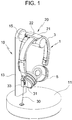
FIG. 1 is a perspective view showing a state in which headphones are cradled on a charging stand for headphones according to the present invention; and -
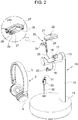
FIG. 2 is an exploded perspective view ofFIG. 1 . - Hereinbelow, exemplary embodiments of a charging state for headphones according to the present invention will be described in detail with reference to the accompanying drawings. Prior to describing the charging stand for headphones according to the present invention in more detail, the present invention will now be described in detail based on aspects (or embodiments). The present invention may, however, be embodied in many different forms and should not be construed as being limited to only the embodiments set forth herein, but should be construed as covering modifications, equivalents or alternatives falling within ideas and technical scopes of the present invention.
- In the figures, like reference numerals, particularly, tens and units, or reference numerals having like tens, units and letters refer to like elements having like functions throughout, and unless the context clearly indicates otherwise, elements referred to by reference numerals of the drawings should be understood based on this standard.
- Also, for convenience of understanding of the elements, in the figures, sizes or thicknesses may be exaggerated to be large (or thick), may be expressed to be small (or thin) or may be simplified for clarity of illustration, but due to this, the protective scope of the present invention should not be interpreted narrowly.
- The terminology used herein is for the purpose of describing particular aspects (or embodiments) only and is not intended to be limiting of the present invention. As used herein, the singular forms are intended to include the plural forms as well, unless the context clearly indicates otherwise. It will be further understood that the terms "comprises", "comprising", "includes" and/or "including" when used herein, specify the presence of stated features, integers, steps, operations, elements, and/or components, but do not preclude the presence or addition of one or more other features, integers, steps, operations, elements, components, and/or groups thereof.
- Unless otherwise defined, all terms including technical and scientific terms used herein have the same meaning as commonly understood by one of ordinary skill in the art to which the present invention belongs. It will be further understood that terms used herein should be interpreted as having a meaning that is consistent with their meaning in the context of this specification and the relevant art and will not be interpreted in an idealized or overly formal sense unless expressly so defined herein.
- As shown in the drawings, a charging stand for headphones according to the present invention is roughly divided into a
cradle 10, acharging cable 20, and anantitheft wire 30. - The
cradle 10 is a mechanism on which the headphones are cradled to be displayed. - The
cradle 10 includes asupport 11 placed on a surface, apost 13 vertically extending from thesupport 11 , and acradling arm 15 horizontally extending from an upper portion of thepost 13. - The
cradling arm 15 has acradling portion 16 formed in an upper side thereof and on which aheadband portion 3 of the headphones 1 is cradled. Thecradling portion 16 has a depression structure rounded correspondingly to the shape of theheadband portion 3 such that theheadband portion 3 of the headphones 1 is seated and cradled thereon. - The
cradling portion 16 has opposite sides each provided with aflat surface portion 17, and theflat surface portion 17 formed at one of the opposite sides of the cradling portion is provided with acharging terminal 18. The chargingterminal 18 supplies electric power for charging the headphones 1 . - It is preferable that the
charging terminal 18 has a protrusion structure and is configured to be elastically supported inside the flat surface portion to be insertable and extendable, such that thecharging terminal 18 is brought into close contact with aconnection terminal 28 of aholder 21 of thecharging cable 20. - The
charging cable 20 includes theholder 21 , aconnection pin 23, and awire 25 electrically connecting the holder and the connecting pin to each other. - The
holder 21 is configured to hold theheadband portion 3 of the headphones 1, and theconnection pin 23 is electrically connectable to a charging port provided at anearpiece portion 5 of the headphones 1 . - The
holder 21 has aseat depression 21 h formed in a lower surface thereof and which is configured to hold theheadband portion 3 of the headphones 1. Theseat depression 21h is provided with aclamper 26 elastically holding an inner surface of theheadband portion 13 of the headphones 1 when theheadband portion 13 is placed below theseat depression 21h. - The
seat depression 21h has opposite sides each provided with a supportedportion 27 configured to be placed on theflat surface portion 17 of thecradle 10.
Furthermore, the supportedportion 27 formed at one of the opposite sides of the seat depression is provided with theconnection terminal 28 configured to come into contact with thecharging terminal 18 and apower switch 29 shutting off unnecessary power supply after charging of the headphones is completed. - The
connection terminal 28 is supplied with electric power via thecharging terminal 18 and supplies the supplied electric power to a battery built in theearpiece portion 5 of the headphones 1 via theconnection pin 23 and the charging port to charge the battery. - The
holder 21 is provided on an upper surface thereof with a power-indicatingLED lamp 22 for checking whether the electric power supplied to theconnection terminal 28 is supplied to the battery via theconnection pin 23. - To prevent the charging
cable 20 from being separated from the headphones 1 and falling off a surface, thus being damaged, stolen, or lost, it is preferable that thewire 25 of the chargingcable 20 is tied to theheadband portion 3 of the headphones 1 by amember 24 such as a rubber ring. - The
anti-theft wire 30 is connected to the headphones 1 to prevent the headphones 1 from being moved outside the length range of thewire 30, thus preventing the headphones 1 from being stolen. - The
anti-theft wire 30 extends from thesupport 11 of thecradle 10. Thewire 30 may be built in thesupport 11 in a state of being wound like a spring so as to be inserted into and extended from thesupport 11 or may be provided at an inner side of a display table (not shown), the display table on which thesupport 11 is mounted, in a state of being wound like a spring by passing through thesupport 11 so as to be inserted into and extended from thesupport 11 . - The
anti-theft wire 30 has aloop 31 formed at an end portion thereof and surrounding the outer periphery of theheadband portion 3 of the headphones 1. Thewire 30 is provided at the end portion thereof with aloop adjusting member 33 such that theloop 31 formed by thewire 30 is adjustable in size. Theloop 31 is increased in size to pass over theearpiece portion 5 of the headphones 1 and is then decreased in size, thus being fastened to the headphones 1 . - If the
anti-theft wire 30 is cut or the size of theloop 31 is arbitrarily changed, a theft of the headphones 1 may be attempted. In this case, an alarm detects this and outputs an alarm sound, thus preventing the headphones 1 from being stolen. - The
anti-theft wire 30 is comprised of a metal cable which is not easily cut and a power line through which electric power flows, and is connected to the alarm. Accordingly, when thewire 30 is cut (that is, the power line is cut) and thus the electric power does not flow, or when the size of the loop is changed and thus the resistance of the power line is changed, the alarm detects this. - Although the exemplary embodiments of the present invention have been described for illustrative purposes, those skilled in the art will appreciate that various modifications, additions and substitutions are possible, without departing from the scope as disclosed in the accompanying claims.
Claims (3)
- A charging stand for headphones, the charging stand
comprising:a cradle (10) having a cradling portion (16) on which the headphones (1) are cradled, a flat surface portion (17) provided at a side of the cradling portion (16), and a charging terminal (18) provided at the flat surface portion (17); anda charging cable (20) having a holder (21) and a connection pin (23), the holder (21) being provided with a seat depression (21h) which is configured to hold a headband portion (3) of the headphones (1), a supported portion (27) formed at a side of the seat depression (21h) and configured to be placed on the flat surface portion (17), a connection terminal (28) provided at the supported portion (27) and configured to come into contact with the charging terminal (18), and a clamper (26) elastically holding an inner surface of the headband portion (3) when the headband portion (3) is placed below the seat depression (21h), and the connection pin (23) being electrically connected to the connection terminal (28) and electrically connectable to a charging port of the headphones (1). - The charging stand of claim 1, further comprising: an anti-theft wire (30) extending from a support (11) of the cradle (10) and having an end portion configured to be connected to the headphones (10).
- The charging stand of claim 2, wherein the wire (30) is provided at the end portion thereof with a loop adjusting member (33) configured to adjust a size of a loop (31) surrounding an outer periphery of the headband portion (3) of the headphones (1), and an alarm which outputs an alarm sound when the wire (30) is cut or the size of the loop (31) formed by the loop adjusting member (33) is changed is further provided.
Applications Claiming Priority (1)
| Application Number | Priority Date | Filing Date | Title |
|---|---|---|---|
| KR1020180004623A KR101927245B1 (en) | 2018-01-12 | 2018-01-12 | Stands combined charger for headphones |
Publications (2)
| Publication Number | Publication Date |
|---|---|
| EP3512211A1 EP3512211A1 (en) | 2019-07-17 |
| EP3512211B1 true EP3512211B1 (en) | 2021-03-24 |
Family
ID=64670345
Family Applications (1)
| Application Number | Title | Priority Date | Filing Date |
|---|---|---|---|
| EP19151319.1A Active EP3512211B1 (en) | 2018-01-12 | 2019-01-11 | Charging stand for headphones |
Country Status (6)
| Country | Link |
|---|---|
| US (1) | US10390121B2 (en) |
| EP (1) | EP3512211B1 (en) |
| KR (1) | KR101927245B1 (en) |
| CN (1) | CN110035345A (en) |
| ES (1) | ES2869426T3 (en) |
| PT (1) | PT3512211T (en) |
Families Citing this family (37)
| Publication number | Priority date | Publication date | Assignee | Title |
|---|---|---|---|---|
| USD898000S1 (en) * | 2018-09-13 | 2020-10-06 | Plantronics, Inc. | Base cradle for a communications headset |
| USD868753S1 (en) * | 2018-09-25 | 2019-12-03 | Timothy Val Kolton | Headphone holder |
| US10993017B2 (en) * | 2019-09-19 | 2021-04-27 | Ningombam Aryamann Singh | Smart earbud device of an earphone |
| US11234068B2 (en) * | 2019-12-16 | 2022-01-25 | Gn Audio A/S | Wireless hearing device and a charging base |
| TWM596505U (en) * | 2020-02-07 | 2020-06-01 | 正崴精密工業股份有限公司 | Bluetooth wireless headset |
| CN111800703B (en) * | 2020-07-29 | 2022-03-15 | 安徽金河电子科技有限公司 | Headset with charging seat |
| CN111864863B (en) * | 2020-08-20 | 2025-02-25 | 厦门亿联网络技术股份有限公司 | A charging stand |
| JP1681673S (en) * | 2020-09-17 | 2021-03-22 | ||
| CN112235708B (en) * | 2020-10-29 | 2022-07-15 | 深圳市安特信技术有限公司 | A test system and method for earphone production |
| USD951920S1 (en) * | 2021-01-07 | 2022-05-17 | Sariana, LLC | Headphone stand with charger |
| USD951919S1 (en) * | 2021-01-07 | 2022-05-17 | Sariana, LLC | Headphone stand |
| USD956022S1 (en) * | 2021-01-28 | 2022-06-28 | Sariana, LLC | Headphone stand with charger |
| USD1005269S1 (en) * | 2021-06-10 | 2023-11-21 | Xiwan Sun | Headphone stand |
| USD986225S1 (en) * | 2021-07-27 | 2023-05-16 | HumanCentric Ventures LLC | Headphone stand |
| USD989527S1 (en) * | 2021-08-13 | 2023-06-20 | Apple Inc. | Display stand |
| USD963617S1 (en) * | 2022-01-06 | 2022-09-13 | Shen Zhen Yaan Energy Technology Co., Ltd. | Headset holder |
| TWD222260S (en) * | 2022-05-04 | 2022-11-21 | 宏碁股份有限公司 | Headphone stand |
| USD1076886S1 (en) | 2022-12-02 | 2025-05-27 | Sonos, Inc. | Wall mount for an audio device |
| USD1076885S1 (en) | 2022-12-02 | 2025-05-27 | Sonos, Inc. | Wall mount for an audio device |
| USD1045836S1 (en) * | 2022-12-02 | 2024-10-08 | Sonos, Inc. | Stand for an audio device |
| USD1044782S1 (en) * | 2022-12-02 | 2024-10-01 | Sonos, Inc. | Wall mount for an audio device |
| USD1073651S1 (en) | 2022-12-02 | 2025-05-06 | Sonos, Inc. | Wall mount for an audio device |
| USD1005981S1 (en) * | 2023-02-03 | 2023-11-28 | Fang Guo | Combined headphone and charging stand |
| USD1062702S1 (en) * | 2023-02-17 | 2025-02-18 | Guangtang Yu | Holder for virtual reality headset |
| USD1038087S1 (en) * | 2023-03-17 | 2024-08-06 | Shenzhen Haoyi Electronic Technology Co., Ltd. | Headset holder |
| USD1046826S1 (en) * | 2023-04-17 | 2024-10-15 | Shenzhen Haoyi Electronic Technology Co., Ltd. | Gamepad holder |
| USD1081632S1 (en) * | 2023-09-21 | 2025-07-01 | Guangzhou Zhongtianxin Electronic Technology, Co. Ltd. | Socket headphone rack |
| USD1080590S1 (en) * | 2023-09-21 | 2025-06-24 | Guangzhou Zhongtianxin Electronic Technology Co., Ltd | Earphone hanger |
| USD1090498S1 (en) * | 2023-09-28 | 2025-08-26 | Jinhong Wu | VR stand |
| USD1011320S1 (en) * | 2023-10-31 | 2024-01-16 | Xiaorong Chen | Headphone stand |
| TWI881539B (en) * | 2023-11-13 | 2025-04-21 | 香港商冠捷投資有限公司 | Headphones holder and monitor |
| IL313240A (en) * | 2024-05-30 | 2025-12-01 | Angelo Shawky Shaheen | Portable audio system |
| USD1041458S1 (en) * | 2024-06-21 | 2024-09-10 | Shenzhen Zhiyoumei Technology Co., Ltd | Headphone holder |
| US12484717B1 (en) * | 2024-08-06 | 2025-12-02 | Chris Kieres | Wall mount band holder system and method |
| USD1053847S1 (en) * | 2024-08-09 | 2024-12-10 | Shenzhen Changtingwan Technology Co., Ltd. | Headphone and stand |
| USD1101724S1 (en) * | 2024-09-27 | 2025-11-11 | Zhongshan Liangda Trading Co., Ltd. | Headphone stand |
| USD1123905S1 (en) * | 2025-04-15 | 2026-04-28 | Yongqin Chen | Headphone hanger |
Family Cites Families (24)
| Publication number | Priority date | Publication date | Assignee | Title |
|---|---|---|---|---|
| JP2870791B2 (en) * | 1989-03-20 | 1999-03-17 | ソニー株式会社 | Wireless headphones |
| KR200234963Y1 (en) | 2001-03-31 | 2001-10-10 | 주식회사 니오스 | Infrared transmitter and wireless headphone |
| JP3794363B2 (en) * | 2002-09-13 | 2006-07-05 | ソニー株式会社 | Charging apparatus and charging method |
| DE102004001442A1 (en) * | 2004-01-08 | 2005-09-22 | Sennheiser Electronic Gmbh & Co. Kg | headphone |
| KR20050097590A (en) | 2004-04-01 | 2005-10-10 | 주식회사 에이엠지테크놀러지 | Rf headset unit |
| US8170623B2 (en) * | 2006-11-17 | 2012-05-01 | Apple Inc. | Charging arrangement for electronic accessories |
| CN201181506Y (en) * | 2008-02-04 | 2009-01-14 | 广州市恒颖贸易有限公司 | Anti-theft alarm sensing device for commercial articles exhibition |
| US20100137038A1 (en) * | 2008-12-01 | 2010-06-03 | Plantronics, Inc. | Interchangeable Docking Cradle |
| DK2521242T3 (en) * | 2009-10-08 | 2014-03-17 | Sennheiser Comm As | Base station, wireless headset and headband thereto. |
| US8593573B2 (en) * | 2009-12-14 | 2013-11-26 | VIZIO Inc. | System, method and apparatus for detecting docking of headphones |
| US8744098B2 (en) * | 2010-02-04 | 2014-06-03 | Apple Inc. | Using an audio cable as an inductive charging coil |
| CN201774653U (en) * | 2010-05-06 | 2011-03-23 | 黄瑞法 | Earphone rack |
| US9008328B2 (en) * | 2011-09-28 | 2015-04-14 | Tdk Corporation | Headphone, headphone stand and headphone system |
| KR101429394B1 (en) * | 2013-03-11 | 2014-08-12 | 박수진 | Supporter for mobile device |
| CN204022150U (en) * | 2014-06-16 | 2014-12-17 | 深圳市非凡创新实业有限公司 | The line clamping device of mobile device |
| CN204231611U (en) * | 2014-10-15 | 2015-03-25 | 雷东玉 | A kind of folding wireless charging headset system |
| CN204650689U (en) * | 2015-05-18 | 2015-09-16 | 杭州朗鸿科技有限公司 | Band has the antitheft exhibiting device of the mobile phone of the annex of auxiliary operation function |
| CN204948316U (en) * | 2015-09-17 | 2016-01-06 | 加一联创电子科技有限公司 | A kind of ear frame |
| CN205385585U (en) * | 2015-12-25 | 2016-07-13 | 惠州市新耀胶粘材料有限公司 | Earphone rack |
| CN205647886U (en) * | 2016-03-30 | 2016-10-12 | 广东佳禾声学科技有限公司 | Anti-theft earphone for case |
| CN105932753B (en) * | 2016-07-08 | 2018-11-16 | 李晓刚 | Magnetic mobile phone charging bracket and magnetic charging equipment for mobile phone |
| CN206525859U (en) * | 2016-12-08 | 2017-09-29 | 杭州辰普科技有限公司 | A kind of Anti-theft show shelf of cell phone |
| CN106451691A (en) * | 2016-12-16 | 2017-02-22 | 深圳市深联创电子有限公司 | Wireless charging device |
| KR101795557B1 (en) | 2017-01-25 | 2017-11-08 | 주식회사 알티텍 | Wireless charging device |
-
2018
- 2018-01-12 KR KR1020180004623A patent/KR101927245B1/en active Active
-
2019
- 2019-01-07 CN CN201910010939.9A patent/CN110035345A/en active Pending
- 2019-01-10 US US16/244,703 patent/US10390121B2/en active Active
- 2019-01-11 PT PT191513191T patent/PT3512211T/en unknown
- 2019-01-11 EP EP19151319.1A patent/EP3512211B1/en active Active
- 2019-01-11 ES ES19151319T patent/ES2869426T3/en active Active
Non-Patent Citations (1)
| Title |
|---|
| None * |
Also Published As
| Publication number | Publication date |
|---|---|
| US20190222916A1 (en) | 2019-07-18 |
| PT3512211T (en) | 2021-05-05 |
| ES2869426T3 (en) | 2021-10-25 |
| EP3512211A1 (en) | 2019-07-17 |
| CN110035345A (en) | 2019-07-19 |
| US10390121B2 (en) | 2019-08-20 |
| KR101927245B1 (en) | 2018-12-10 |
Similar Documents
| Publication | Publication Date | Title |
|---|---|---|
| EP3512211B1 (en) | Charging stand for headphones | |
| US8873250B2 (en) | Attachable extendable and retractable earpiece cable assembly for mobile communication and sound devices | |
| US11190035B2 (en) | Device for charging portable electronic devices | |
| KR101076050B1 (en) | Bluetooth headset for helmet with intercom function | |
| US20160173667A1 (en) | Magnetic mobile phone mounting kit | |
| US7664540B2 (en) | Bluetooth earphone set with wire control function | |
| US20090069060A1 (en) | Clip-on wireless device with retractable ear piece | |
| US20030157973A1 (en) | Easy to carry hands-free kit containing earpiece inside the carrying case | |
| JP2020522209A (en) | Smart holder | |
| CA2867443A1 (en) | Integrated, detachable ear bud device for a wireless phone | |
| US9271061B1 (en) | Personal detachable multipurpose wireless armband loudspeaker system | |
| KR20190103674A (en) | A case for wireless earphone | |
| EP1326410A1 (en) | Handsfree wireless communication system for handsfree communication between a user and a mobile phone | |
| CN101442145A (en) | Vehicle-mounted Bluetooth multifunctional charger | |
| CN219919124U (en) | Earphone with ear clip structure | |
| KR20060097686A (en) | Portable wireless headset | |
| CN215529275U (en) | Can dismantle module bluetooth headset | |
| US20140036469A1 (en) | Protection Device for Mobile Apparatus with Bluetooth Earphone | |
| CN211509271U (en) | Bluetooth earphone suite with automatic playing function of external sound | |
| CN209419828U (en) | A kind of wireless audio receiver | |
| KR20170069827A (en) | Auxiliary battery charger of a mobile phone provided with a stand that can be size adjustment | |
| CN201315333Y (en) | Vehicle Bluetooth multifunctional charger | |
| CN210839998U (en) | Earphone set | |
| CN222474851U (en) | Multifunctional mobile phone storage box | |
| CN217135186U (en) | Clamping type charging device capable of being pulled manually |
Legal Events
| Date | Code | Title | Description |
|---|---|---|---|
| PUAI | Public reference made under article 153(3) epc to a published international application that has entered the european phase |
Free format text: ORIGINAL CODE: 0009012 |
|
| STAA | Information on the status of an ep patent application or granted ep patent |
Free format text: STATUS: THE APPLICATION HAS BEEN PUBLISHED |
|
| AK | Designated contracting states |
Kind code of ref document: A1 Designated state(s): AL AT BE BG CH CY CZ DE DK EE ES FI FR GB GR HR HU IE IS IT LI LT LU LV MC MK MT NL NO PL PT RO RS SE SI SK SM TR |
|
| AX | Request for extension of the european patent |
Extension state: BA ME |
|
| STAA | Information on the status of an ep patent application or granted ep patent |
Free format text: STATUS: REQUEST FOR EXAMINATION WAS MADE |
|
| 17P | Request for examination filed |
Effective date: 20191030 |
|
| RBV | Designated contracting states (corrected) |
Designated state(s): AL AT BE BG CH CY CZ DE DK EE ES FI FR GB GR HR HU IE IS IT LI LT LU LV MC MK MT NL NO PL PT RO RS SE SI SK SM TR |
|
| GRAP | Despatch of communication of intention to grant a patent |
Free format text: ORIGINAL CODE: EPIDOSNIGR1 |
|
| STAA | Information on the status of an ep patent application or granted ep patent |
Free format text: STATUS: GRANT OF PATENT IS INTENDED |
|
| RIC1 | Information provided on ipc code assigned before grant |
Ipc: H04R 1/10 20060101AFI20200922BHEP |
|
| INTG | Intention to grant announced |
Effective date: 20201013 |
|
| GRAS | Grant fee paid |
Free format text: ORIGINAL CODE: EPIDOSNIGR3 |
|
| GRAA | (expected) grant |
Free format text: ORIGINAL CODE: 0009210 |
|
| STAA | Information on the status of an ep patent application or granted ep patent |
Free format text: STATUS: THE PATENT HAS BEEN GRANTED |
|
| AK | Designated contracting states |
Kind code of ref document: B1 Designated state(s): AL AT BE BG CH CY CZ DE DK EE ES FI FR GB GR HR HU IE IS IT LI LT LU LV MC MK MT NL NO PL PT RO RS SE SI SK SM TR |
|
| REG | Reference to a national code |
Ref country code: GB Ref legal event code: FG4D |
|
| REG | Reference to a national code |
Ref country code: CH Ref legal event code: EP |
|
| REG | Reference to a national code |
Ref country code: IE Ref legal event code: FG4D |
|
| REG | Reference to a national code |
Ref country code: DE Ref legal event code: R096 Ref document number: 602019003287 Country of ref document: DE Ref country code: AT Ref legal event code: REF Ref document number: 1375721 Country of ref document: AT Kind code of ref document: T Effective date: 20210415 |
|
| REG | Reference to a national code |
Ref country code: PT Ref legal event code: SC4A Ref document number: 3512211 Country of ref document: PT Date of ref document: 20210505 Kind code of ref document: T Free format text: AVAILABILITY OF NATIONAL TRANSLATION Effective date: 20210428 |
|
| REG | Reference to a national code |
Ref country code: SE Ref legal event code: TRGR |
|
| REG | Reference to a national code |
Ref country code: NL Ref legal event code: FP |
|
| REG | Reference to a national code |
Ref country code: LT Ref legal event code: MG9D |
|
| PG25 | Lapsed in a contracting state [announced via postgrant information from national office to epo] |
Ref country code: NO Free format text: LAPSE BECAUSE OF FAILURE TO SUBMIT A TRANSLATION OF THE DESCRIPTION OR TO PAY THE FEE WITHIN THE PRESCRIBED TIME-LIMIT Effective date: 20210624 Ref country code: BG Free format text: LAPSE BECAUSE OF FAILURE TO SUBMIT A TRANSLATION OF THE DESCRIPTION OR TO PAY THE FEE WITHIN THE PRESCRIBED TIME-LIMIT Effective date: 20210624 Ref country code: HR Free format text: LAPSE BECAUSE OF FAILURE TO SUBMIT A TRANSLATION OF THE DESCRIPTION OR TO PAY THE FEE WITHIN THE PRESCRIBED TIME-LIMIT Effective date: 20210324 Ref country code: GR Free format text: LAPSE BECAUSE OF FAILURE TO SUBMIT A TRANSLATION OF THE DESCRIPTION OR TO PAY THE FEE WITHIN THE PRESCRIBED TIME-LIMIT Effective date: 20210625 Ref country code: FI Free format text: LAPSE BECAUSE OF FAILURE TO SUBMIT A TRANSLATION OF THE DESCRIPTION OR TO PAY THE FEE WITHIN THE PRESCRIBED TIME-LIMIT Effective date: 20210324 |
|
| PG25 | Lapsed in a contracting state [announced via postgrant information from national office to epo] |
Ref country code: RS Free format text: LAPSE BECAUSE OF FAILURE TO SUBMIT A TRANSLATION OF THE DESCRIPTION OR TO PAY THE FEE WITHIN THE PRESCRIBED TIME-LIMIT Effective date: 20210324 Ref country code: LV Free format text: LAPSE BECAUSE OF FAILURE TO SUBMIT A TRANSLATION OF THE DESCRIPTION OR TO PAY THE FEE WITHIN THE PRESCRIBED TIME-LIMIT Effective date: 20210324 |
|
| REG | Reference to a national code |
Ref country code: AT Ref legal event code: MK05 Ref document number: 1375721 Country of ref document: AT Kind code of ref document: T Effective date: 20210324 |
|
| REG | Reference to a national code |
Ref country code: ES Ref legal event code: FG2A Ref document number: 2869426 Country of ref document: ES Kind code of ref document: T3 Effective date: 20211025 |
|
| PG25 | Lapsed in a contracting state [announced via postgrant information from national office to epo] |
Ref country code: LT Free format text: LAPSE BECAUSE OF FAILURE TO SUBMIT A TRANSLATION OF THE DESCRIPTION OR TO PAY THE FEE WITHIN THE PRESCRIBED TIME-LIMIT Effective date: 20210324 Ref country code: CZ Free format text: LAPSE BECAUSE OF FAILURE TO SUBMIT A TRANSLATION OF THE DESCRIPTION OR TO PAY THE FEE WITHIN THE PRESCRIBED TIME-LIMIT Effective date: 20210324 Ref country code: EE Free format text: LAPSE BECAUSE OF FAILURE TO SUBMIT A TRANSLATION OF THE DESCRIPTION OR TO PAY THE FEE WITHIN THE PRESCRIBED TIME-LIMIT Effective date: 20210324 Ref country code: AT Free format text: LAPSE BECAUSE OF FAILURE TO SUBMIT A TRANSLATION OF THE DESCRIPTION OR TO PAY THE FEE WITHIN THE PRESCRIBED TIME-LIMIT Effective date: 20210324 Ref country code: SM Free format text: LAPSE BECAUSE OF FAILURE TO SUBMIT A TRANSLATION OF THE DESCRIPTION OR TO PAY THE FEE WITHIN THE PRESCRIBED TIME-LIMIT Effective date: 20210324 |
|
| PG25 | Lapsed in a contracting state [announced via postgrant information from national office to epo] |
Ref country code: PL Free format text: LAPSE BECAUSE OF FAILURE TO SUBMIT A TRANSLATION OF THE DESCRIPTION OR TO PAY THE FEE WITHIN THE PRESCRIBED TIME-LIMIT Effective date: 20210324 Ref country code: SK Free format text: LAPSE BECAUSE OF FAILURE TO SUBMIT A TRANSLATION OF THE DESCRIPTION OR TO PAY THE FEE WITHIN THE PRESCRIBED TIME-LIMIT Effective date: 20210324 Ref country code: RO Free format text: LAPSE BECAUSE OF FAILURE TO SUBMIT A TRANSLATION OF THE DESCRIPTION OR TO PAY THE FEE WITHIN THE PRESCRIBED TIME-LIMIT Effective date: 20210324 Ref country code: IS Free format text: LAPSE BECAUSE OF FAILURE TO SUBMIT A TRANSLATION OF THE DESCRIPTION OR TO PAY THE FEE WITHIN THE PRESCRIBED TIME-LIMIT Effective date: 20210724 |
|
| REG | Reference to a national code |
Ref country code: DE Ref legal event code: R097 Ref document number: 602019003287 Country of ref document: DE |
|
| PG25 | Lapsed in a contracting state [announced via postgrant information from national office to epo] |
Ref country code: DK Free format text: LAPSE BECAUSE OF FAILURE TO SUBMIT A TRANSLATION OF THE DESCRIPTION OR TO PAY THE FEE WITHIN THE PRESCRIBED TIME-LIMIT Effective date: 20210324 Ref country code: AL Free format text: LAPSE BECAUSE OF FAILURE TO SUBMIT A TRANSLATION OF THE DESCRIPTION OR TO PAY THE FEE WITHIN THE PRESCRIBED TIME-LIMIT Effective date: 20210324 |
|
| PLBE | No opposition filed within time limit |
Free format text: ORIGINAL CODE: 0009261 |
|
| STAA | Information on the status of an ep patent application or granted ep patent |
Free format text: STATUS: NO OPPOSITION FILED WITHIN TIME LIMIT |
|
| PG25 | Lapsed in a contracting state [announced via postgrant information from national office to epo] |
Ref country code: SI Free format text: LAPSE BECAUSE OF FAILURE TO SUBMIT A TRANSLATION OF THE DESCRIPTION OR TO PAY THE FEE WITHIN THE PRESCRIBED TIME-LIMIT Effective date: 20210324 |
|
| 26N | No opposition filed |
Effective date: 20220104 |
|
| PG25 | Lapsed in a contracting state [announced via postgrant information from national office to epo] |
Ref country code: IS Free format text: LAPSE BECAUSE OF FAILURE TO SUBMIT A TRANSLATION OF THE DESCRIPTION OR TO PAY THE FEE WITHIN THE PRESCRIBED TIME-LIMIT Effective date: 20210724 |
|
| PG25 | Lapsed in a contracting state [announced via postgrant information from national office to epo] |
Ref country code: MC Free format text: LAPSE BECAUSE OF FAILURE TO SUBMIT A TRANSLATION OF THE DESCRIPTION OR TO PAY THE FEE WITHIN THE PRESCRIBED TIME-LIMIT Effective date: 20210324 |
|
| REG | Reference to a national code |
Ref country code: CH Ref legal event code: PL |
|
| REG | Reference to a national code |
Ref country code: BE Ref legal event code: MM Effective date: 20220131 |
|
| PG25 | Lapsed in a contracting state [announced via postgrant information from national office to epo] |
Ref country code: LU Free format text: LAPSE BECAUSE OF NON-PAYMENT OF DUE FEES Effective date: 20220111 |
|
| PG25 | Lapsed in a contracting state [announced via postgrant information from national office to epo] |
Ref country code: BE Free format text: LAPSE BECAUSE OF NON-PAYMENT OF DUE FEES Effective date: 20220131 |
|
| PG25 | Lapsed in a contracting state [announced via postgrant information from national office to epo] |
Ref country code: LI Free format text: LAPSE BECAUSE OF NON-PAYMENT OF DUE FEES Effective date: 20220131 Ref country code: CH Free format text: LAPSE BECAUSE OF NON-PAYMENT OF DUE FEES Effective date: 20220131 |
|
| PG25 | Lapsed in a contracting state [announced via postgrant information from national office to epo] |
Ref country code: IE Free format text: LAPSE BECAUSE OF NON-PAYMENT OF DUE FEES Effective date: 20220111 |
|
| P01 | Opt-out of the competence of the unified patent court (upc) registered |
Effective date: 20230617 |
|
| PG25 | Lapsed in a contracting state [announced via postgrant information from national office to epo] |
Ref country code: MK Free format text: LAPSE BECAUSE OF FAILURE TO SUBMIT A TRANSLATION OF THE DESCRIPTION OR TO PAY THE FEE WITHIN THE PRESCRIBED TIME-LIMIT Effective date: 20210324 Ref country code: CY Free format text: LAPSE BECAUSE OF FAILURE TO SUBMIT A TRANSLATION OF THE DESCRIPTION OR TO PAY THE FEE WITHIN THE PRESCRIBED TIME-LIMIT Effective date: 20210324 |
|
| PG25 | Lapsed in a contracting state [announced via postgrant information from national office to epo] |
Ref country code: HU Free format text: LAPSE BECAUSE OF FAILURE TO SUBMIT A TRANSLATION OF THE DESCRIPTION OR TO PAY THE FEE WITHIN THE PRESCRIBED TIME-LIMIT; INVALID AB INITIO Effective date: 20190111 |
|
| PG25 | Lapsed in a contracting state [announced via postgrant information from national office to epo] |
Ref country code: MT Free format text: LAPSE BECAUSE OF FAILURE TO SUBMIT A TRANSLATION OF THE DESCRIPTION OR TO PAY THE FEE WITHIN THE PRESCRIBED TIME-LIMIT Effective date: 20210324 |
|
| PGFP | Annual fee paid to national office [announced via postgrant information from national office to epo] |
Ref country code: PT Payment date: 20251216 Year of fee payment: 8 |
|
| PGFP | Annual fee paid to national office [announced via postgrant information from national office to epo] |
Ref country code: NL Payment date: 20260120 Year of fee payment: 8 |
|
| PGFP | Annual fee paid to national office [announced via postgrant information from national office to epo] |
Ref country code: SE Payment date: 20260122 Year of fee payment: 8 |
|
| PGFP | Annual fee paid to national office [announced via postgrant information from national office to epo] |
Ref country code: GB Payment date: 20260121 Year of fee payment: 8 |
|
| PGFP | Annual fee paid to national office [announced via postgrant information from national office to epo] |
Ref country code: ES Payment date: 20260204 Year of fee payment: 8 |
|
| PGFP | Annual fee paid to national office [announced via postgrant information from national office to epo] |
Ref country code: DE Payment date: 20260122 Year of fee payment: 8 |
|
| PGFP | Annual fee paid to national office [announced via postgrant information from national office to epo] |
Ref country code: IT Payment date: 20260127 Year of fee payment: 8 |
|
| PGFP | Annual fee paid to national office [announced via postgrant information from national office to epo] |
Ref country code: FR Payment date: 20260120 Year of fee payment: 8 |
|
| PGFP | Annual fee paid to national office [announced via postgrant information from national office to epo] |
Ref country code: TR Payment date: 20260107 Year of fee payment: 8 |