EP3512130A1 - Measuring device and method with efficient channel simulation - Google Patents
Measuring device and method with efficient channel simulation Download PDFInfo
- Publication number
- EP3512130A1 EP3512130A1 EP18150922.5A EP18150922A EP3512130A1 EP 3512130 A1 EP3512130 A1 EP 3512130A1 EP 18150922 A EP18150922 A EP 18150922A EP 3512130 A1 EP3512130 A1 EP 3512130A1
- Authority
- EP
- European Patent Office
- Prior art keywords
- tap
- mod
- taps
- measuring
- signal
- Prior art date
- Legal status (The legal status is an assumption and is not a legal conclusion. Google has not performed a legal analysis and makes no representation as to the accuracy of the status listed.)
- Ceased
Links
- 238000000034 method Methods 0.000 title claims description 19
- 238000004088 simulation Methods 0.000 title description 8
- 239000003607 modifier Substances 0.000 claims abstract description 18
- 238000012360 testing method Methods 0.000 claims description 36
- 230000008569 process Effects 0.000 claims description 8
- 230000003111 delayed effect Effects 0.000 claims description 6
- 230000005540 biological transmission Effects 0.000 claims description 5
- 238000004590 computer program Methods 0.000 claims description 4
- 230000001934 delay Effects 0.000 description 8
- 230000006870 function Effects 0.000 description 4
- 230000004044 response Effects 0.000 description 4
- 230000007274 generation of a signal involved in cell-cell signaling Effects 0.000 description 2
- 238000005259 measurement Methods 0.000 description 2
- 230000009467 reduction Effects 0.000 description 2
- 230000001419 dependent effect Effects 0.000 description 1
- 238000011161 development Methods 0.000 description 1
- 230000018109 developmental process Effects 0.000 description 1
- 238000010586 diagram Methods 0.000 description 1
- 230000008571 general function Effects 0.000 description 1
- 238000012986 modification Methods 0.000 description 1
- 230000004048 modification Effects 0.000 description 1
- 238000012545 processing Methods 0.000 description 1
Images



Classifications
-
- H—ELECTRICITY
- H04—ELECTRIC COMMUNICATION TECHNIQUE
- H04B—TRANSMISSION
- H04B17/00—Monitoring; Testing
- H04B17/30—Monitoring; Testing of propagation channels
- H04B17/391—Modelling the propagation channel
- H04B17/3912—Simulation models, e.g. distribution of spectral power density or received signal strength indicator [RSSI] for a given geographic region
-
- H—ELECTRICITY
- H04—ELECTRIC COMMUNICATION TECHNIQUE
- H04B—TRANSMISSION
- H04B17/00—Monitoring; Testing
- H04B17/30—Monitoring; Testing of propagation channels
- H04B17/391—Modelling the propagation channel
- H04B17/3911—Fading models or fading generators
Definitions
- the invention relates to simulating a transmission channel in high frequency communications systems.
- BS base station
- UE user equipment
- Channel simulators are available as independent devices that can be integrated into the test setup or they can be part of the test device as independent hardware resource.
- NR For NR, a generic channel model has been defined.
- the defined tap delays have a time resolution of pico seconds [ps]. Simulating the delays with a time resolution of pico seconds results in very high demands on the channel simulator.
- the US patent US 7,852,912 B2 shows an equalizer system with conventional channel simulator.
- the object of the invention is to provide a measuring device and measuring method, which allow a simulation of propagation channels with a reduced hardware requirement.
- a measuring device comprising a channel simulator.
- the channel simulator is adapted to simulate multipath propagation by modifying a first measuring signal, using a plurality of taps defined by tap parameters, resulting in a second measuring signal.
- the measuring device moreover comprises a parameter modifier, adapted to modify input tap parameters, resulting in the tap parameters.
- the parameter modifier is adapted to modify the input tap parameters by rounding tap delay values and/or by combining taps, resulting in the tap parameters.
- the measuring device additionally comprises a signal generator, adapted to generate the first measuring signal, or a signal interface, adapted to receive the first measuring signal.
- the measuring device is moreover optionally adapted to provide the second measuring signal to a device under test. This allows for performing the entire signal generation and channel simulation within the measuring device or alternatively for very flexibly receiving the first measuring signal from an external source. This increases the hardware flexibility, significantly.
- the parameter modifier is adapted to modify the input tap parameters by rounding tap delay values and/or by combining taps, taking a capability of the device under test defined by a capability parameter into account, resulting in the tap parameters. It is no use to provide the second measuring signal with an accuracy that is higher than the accuracy of the device under test. Therefore, by taking the capability parameter of the device under test into account, it is possible to significantly reduce the hardware effort for generating the second measuring signal.
- the measuring device further comprises a parameter storage, adapted to store the capability parameter of the device under test.
- the parameter modifier is then adapted to read the capability parameter of the device under test from the parameter storage. It is thereby assured that for a plurality of different devices under test, a correct signal generating accuracy is chosen.
- the capability parameter of the device under test is a minimal time difference of events in a reception signal, the device under test can process. This minimal time difference corresponds to the time-resolution of the device under test.
- the time-resolution of performing the channel simulation can be set accordingly, which significantly reduces the effort for performing the channel simulation.
- the parameter modifier is adapted to round tap delay values of the input tap parameters to natural number multiples of the minimal time difference of events in a reception signal, the device under test can process. Thereby, it is assured that the maximum testing resolution, which can be achieved with the present device under test, is actually achieved.
- the parameter modifier is adapted to combine the at least two taps of identical rounded tap delay value. This further reduces the necessary hardware effort.
- the parameter modifier is adapted to combine the at least two taps of identical delay values, by adding scattering parameter signals of the at least two taps of identical delay values.
- the channel simulator comprises a plurality of taps.
- Each of the plurality of taps comprises a delay element, each adapted to delay the first measuring signal by a tap-specific tap delay value, resulting in a delayed first measuring signal, for each of the taps.
- Each of the taps moreover comprises a multiplier, which is adapted to multiply the delayed first measuring signal of the respective tap with a tap-specific scattering parameter signal, resulting in a tap output signal for each of the taps.
- the channel simulator moreover comprises an adder, which is adapted to add all tap output signals, resulting in the second measuring signal. A very simple generation of the second measuring signal is thereby achieved.
- a measuring method for simulating a transmission of a first measuring signal through a transmission channel, resulting in a second measuring signal comprises receiving input tap parameters, modifying the input tap parameters, resulting in tap parameters, and simulating multipath propagation by modifying the first measuring signal, using a plurality of taps defined by the tap parameters, resulting in the second measuring signal. This significantly reduces the hardware requirements for performing the measurements.
- FIG. 3 - 5 the function of an embodiment of the inventive measuring device is shown in detail.
- FIG. 6 the function of an embodiment of the inventive measuring method is described. Similar entities and reference numbers in different figures have been partially omitted.
- FIG. 1 a typical measuring device 1 is shown.
- the measuring device 1 here comprises a signal generator 10, which is connected to a channel simulator 11.
- the channel simulator 11 is connected to a device under test 12, which is not part of the measuring device 1.
- the signal generator 10 generates a first measuring signal 13 and provides it to the channel simulator 11.
- the channel simulator 11 simulates a multipath propagation of the first measuring signal 13, resulting in a second measuring signal 14, which is provided to the device under test 12.
- the channel simulator 11 uses tap parameters ⁇ , h as inputs for defining the multipath propagation. While ⁇ is the delay of a single tap, h is a scattering parameter signal. It is important to note that the tap parameters comprise different values of ⁇ and h for each of the taps of the simulated multipath propagation.
- the channel simulator 11 comprises a plurality of taps 20, 21, 22. Each of the taps comprises a delay element 201, 211, 221 and a multiplier 202, 212, 222.
- the inputs of the delay elements 201, 211 and 221 are connected to the signal generator 10.
- the outputs of the delay elements 201, 211 and 221 are connected to inputs of the multipliers 202, 212 and 222.
- Outputs of the multipliers 202, 212 and 222 are connected to a single adder 23, which is connected to the device under test 12.
- the first measuring signal 13 is provided to the delay elements 201, 211 and 221.
- Each of the delay elements 201, 211, 221 delays the first measuring signal 13 by its respective delay value ⁇ 1 , ⁇ 2 , ⁇ n , resulting in delayed first measuring signals 203, 213, 223, which are provided to the multipliers 202, 212 and 222.
- Each multiplier 202, 212, 222 multiplies the respective delayed first measuring signal 203, 213, 223 with a scattering parameter signal h 1 (t), h 2 (t), h n (t), resulting in a tap output signal 204, 214, 224 for each of the taps 20, 21, 22.
- the tap output signals 204, 214, 224 are added up by the adder 23, resulting in the second measuring signal 14.
- the tap parameters ⁇ , h are set according to a specified communications standard. This results in very high hardware requirements imposed on the channel simulator. In many practical cases, this high hardware effort though is not necessary, since the device under test does not have a time resolution necessitating such accurate measuring signal generation. Therefore, it is not necessary that a channel simulator generates delays with a time resolution that is higher than that of the UE.
- a channel simulator that simulates the tap delays as multiples of ⁇ T is shown.
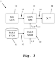
- the measuring device 1 comprises a signal generator 10, connected to a channel simulator 11. Moreover, the measuring device comprises a parameter modifier 30, which is also connected to the channel simulator 11. The measuring device moreover comprises, as an optional component, a parameter storage 31, which is also connected to the parameter modifier 30. As already shown in FIG. 1 , also here, the channel simulator 11 is connected to a device under test 12, which is not part of the measuring device 1.
- the parameter modifier 30 When performing a measurement, the parameter modifier 30 receives input tap parameters ⁇ , h and modifies them to generate tap parameters ⁇ mod , h mod . These tap parameters ⁇ mod , h mod are provided to the channel simulator 11. The signal generator 10 generates a first measuring signal 13, which is provided to the channel simulator 11. The channel simulator 11 now uses the tap parameters ⁇ mod , h mod for performing the channel simulation, as shown along FIG. 2 . It is important to note that the tap parameters ⁇ mod , h mod require lower hardware effort than the input tap parameters ⁇ , h.
- a channel simulator simulates the channel impulse response.
- the power delay profile implemented in the channel simulator 11 would then be: Table 2: Power delay profile implemented from channel simulator Tap k ⁇ k ⁇ mod,k [ns] 1 ⁇ 1 0 2 ⁇ 2 5 3 ⁇ 3 10 4 ⁇ 4 15
- FIG. 4 Such a rounding of tap delay values is shown in FIG. 4 .
- the original power delay profile of the channel simulation is shown.
- the timing of the individual taps is shown, while on the y-axis, the respective power is depicted.
- the timing of the individual taps does not lie on natural number multiples of the minimum time resolution ⁇ T of the device under test.
- Table 4 Power delay profile after rounding of delays Tap k ⁇ k ⁇ mod,k [ns] 1 ⁇ 1 0 2 ⁇ 2 5 3 ⁇ 3 5 4 ⁇ 4 5 5 ⁇ 5 10
- a k , i is the complex amplitude
- f k i is the frequency of subpath i and tap k, respectively.
- FIG. 5 Such a combining of taps is shown in FIG. 5 . While in the top part of FIG. 5 , the original situation of the power delay profile before rounding and combining is shown. It can be seen that the tap with timing approximately 1.7 is rounded to a delay of 2. The taps with timings at 4.8, 5.1 and 5.3 are all rounded to a delay of 5 and combined into a single tap. The tap with a delay of 6.8 is rounded to a delay of 7.
- a first step 100 input tap parameters are received.
- the input tap parameters are modified, so as to achieve the resulting tap parameters.
- a multipath propagation is simulated by modifying a first measuring signal, using a plurality of taps, defined by the tap parameters, resulting in the second measuring signal.
- the invention is not limited to the examples and especially not to a measuring device comprising a signal generator.
- the channel simulator can operate as a stand alone measuring device as well.
- the characteristics of the exemplary embodiments can be implemented in any advantageous combination of the features claimed in the claims, described in the description or drawn in the drawings.
Landscapes
- Physics & Mathematics (AREA)
- Electromagnetism (AREA)
- Engineering & Computer Science (AREA)
- Computer Networks & Wireless Communication (AREA)
- Signal Processing (AREA)
- Spectroscopy & Molecular Physics (AREA)
- Mobile Radio Communication Systems (AREA)
Abstract
A measuring device (1) comprising a channel simulator (11) is provided. The channel simulator (11) is adapted to simulate multipath propagation by modifying a first measuring signal (13), using a plurality of taps defined by tap parameters (τmod, hmod), resulting in a second measuring signal (14). The measuring device (1) moreover comprises a parameter modifier (30), adapted to modify input tap parameters (τ, h), resulting in the tap parameters (τmod, hmod).
Description
- The invention relates to simulating a transmission channel in high frequency communications systems.
- In mobile radio standards such as LTE, GSM, WCDMA etc. or NR (New Radio) (5G), performance requirements for BS (base station) and UEs (user equipment) are defined under certain channel conditions.
- Thus, there is a high demand from both UE and BS vendors for channel simulators. Channel simulators are available as independent devices that can be integrated into the test setup or they can be part of the test device as independent hardware resource.
- For NR, a generic channel model has been defined. The defined tap delays have a time resolution of pico seconds [ps]. Simulating the delays with a time resolution of pico seconds results in very high demands on the channel simulator.
- For example, the US patent
US 7,852,912 B2 shows an equalizer system with conventional channel simulator. - Accordingly, the object of the invention is to provide a measuring device and measuring method, which allow a simulation of propagation channels with a reduced hardware requirement.
- The object is solved by the features of
claim 1 for the device and by the features ofclaim 11 for the method. Further it is solved by the features ofclaims 14 and 15 for the associated computer program and computer program product. The dependent claims contain further developments. - According to a first aspect of the invention, a measuring device comprising a channel simulator is provided. The channel simulator is adapted to simulate multipath propagation by modifying a first measuring signal, using a plurality of taps defined by tap parameters, resulting in a second measuring signal. The measuring device moreover comprises a parameter modifier, adapted to modify input tap parameters, resulting in the tap parameters. By accordingly modifying the input tap parameters, it is possible to build the measuring device using simpler hardware components.
- Preferably, the parameter modifier is adapted to modify the input tap parameters by rounding tap delay values and/or by combining taps, resulting in the tap parameters. By use of these two measures, the time resolution, on which the measuring device needs to operate, is significantly reduced, which allows a significant reduction in hardware complexity.
- Further advantageously, the measuring device additionally comprises a signal generator, adapted to generate the first measuring signal, or a signal interface, adapted to receive the first measuring signal. The measuring device is moreover optionally adapted to provide the second measuring signal to a device under test. This allows for performing the entire signal generation and channel simulation within the measuring device or alternatively for very flexibly receiving the first measuring signal from an external source. This increases the hardware flexibility, significantly.
- Further advantageously, the parameter modifier is adapted to modify the input tap parameters by rounding tap delay values and/or by combining taps, taking a capability of the device under test defined by a capability parameter into account, resulting in the tap parameters. It is no use to provide the second measuring signal with an accuracy that is higher than the accuracy of the device under test. Therefore, by taking the capability parameter of the device under test into account, it is possible to significantly reduce the hardware effort for generating the second measuring signal.
- Advantageously, the measuring device further comprises a parameter storage, adapted to store the capability parameter of the device under test. The parameter modifier is then adapted to read the capability parameter of the device under test from the parameter storage. It is thereby assured that for a plurality of different devices under test, a correct signal generating accuracy is chosen.
- Advantageously, the capability parameter of the device under test is a minimal time difference of events in a reception signal, the device under test can process. This minimal time difference corresponds to the time-resolution of the device under test. By using this capability parameter of the device under test, the time-resolution of performing the channel simulation can be set accordingly, which significantly reduces the effort for performing the channel simulation.
- Advantageously, the parameter modifier is adapted to round tap delay values of the input tap parameters to natural number multiples of the minimal time difference of events in a reception signal, the device under test can process. Thereby, it is assured that the maximum testing resolution, which can be achieved with the present device under test, is actually achieved.
- Further advantageously, if the rounding results in at least two taps having an identical rounded tap delay value, the parameter modifier is adapted to combine the at least two taps of identical rounded tap delay value. This further reduces the necessary hardware effort.
- Advantageously, the parameter modifier is adapted to combine the at least two taps of identical delay values, by adding scattering parameter signals of the at least two taps of identical delay values. By this simple measure, a further reduction in hardware effort is achieved.
- Advantageously, the channel simulator comprises a plurality of taps. Each of the plurality of taps comprises a delay element, each adapted to delay the first measuring signal by a tap-specific tap delay value, resulting in a delayed first measuring signal, for each of the taps. Each of the taps moreover comprises a multiplier, which is adapted to multiply the delayed first measuring signal of the respective tap with a tap-specific scattering parameter signal, resulting in a tap output signal for each of the taps. The channel simulator moreover comprises an adder, which is adapted to add all tap output signals, resulting in the second measuring signal. A very simple generation of the second measuring signal is thereby achieved.
- According to a second aspect of the invention, a measuring method for simulating a transmission of a first measuring signal through a transmission channel, resulting in a second measuring signal is provided. The method comprises receiving input tap parameters, modifying the input tap parameters, resulting in tap parameters, and simulating multipath propagation by modifying the first measuring signal, using a plurality of taps defined by the tap parameters, resulting in the second measuring signal. This significantly reduces the hardware requirements for performing the measurements.
- An exemplary embodiment of the invention is now further explained by way of example only with respect to the drawings, in which
- FIG. 1
- shows an exemplary measuring device;
- FIG. 2
- shows an exemplary channel simulator;
- FIG. 3
- shows an embodiment of the inventive measuring device;
- FIG. 4
- shows a rounding of tap delay values as performed by the embodiment of the inventive measuring device;
- FIG. 5
- shows combined taps as used by the embodiment of the inventive measuring device, and
- FIG. 6
- shows an embodiment of the inventive measuring method, in a flow diagram.
- First, we demonstrate the general function of a measuring device including a channel simulator along
FIG. 1 and FIG. 2 . With regard toFIG. 3 - 5 the function of an embodiment of the inventive measuring device is shown in detail. AlongFIG. 6 , finally, the function of an embodiment of the inventive measuring method is described. Similar entities and reference numbers in different figures have been partially omitted. - In
FIG. 1 , a typicalmeasuring device 1 is shown. Themeasuring device 1 here comprises asignal generator 10, which is connected to achannel simulator 11. Thechannel simulator 11 is connected to a device undertest 12, which is not part of themeasuring device 1. - The
signal generator 10 generates afirst measuring signal 13 and provides it to thechannel simulator 11. Thechannel simulator 11 simulates a multipath propagation of thefirst measuring signal 13, resulting in asecond measuring signal 14, which is provided to the device undertest 12. Thechannel simulator 11 uses tap parameters τ, h as inputs for defining the multipath propagation. While τ is the delay of a single tap, h is a scattering parameter signal. It is important to note that the tap parameters comprise different values of τ and h for each of the taps of the simulated multipath propagation. - Details of the
channel simulator 11 are shown inFIG. 2 . Thechannel simulator 11 comprises a plurality oftaps delay element multiplier delay elements signal generator 10. The outputs of thedelay elements multipliers multipliers single adder 23, which is connected to the device undertest 12. - For performing a channel simulation, the
first measuring signal 13 is provided to thedelay elements delay elements first measuring signal 13 by its respective delay value τ1, τ2, τn, resulting in delayed first measuringsignals multipliers multiplier signal tap output signal taps adder 23, resulting in thesecond measuring signal 14. - In a conventional channel simulator, used in a conventional measuring device or separately, the tap parameters τ, h are set according to a specified communications standard. This results in very high hardware requirements imposed on the channel simulator. In many practical cases, this high hardware effort though is not necessary, since the device under test does not have a time resolution necessitating such accurate measuring signal generation. Therefore, it is not necessary that a channel simulator generates delays with a time resolution that is higher than that of the UE.
- The time resolution ΔT of the UE is given through its signal processing bandwidth BW, i.e.

- In
Fig. 3 , a channel simulator that simulates the tap delays as multiples of ΔT is shown. - The measuring
device 1 according to an embodiment of the present invention, shown inFIG. 3 , comprises asignal generator 10, connected to achannel simulator 11. Moreover, the measuring device comprises aparameter modifier 30, which is also connected to thechannel simulator 11. The measuring device moreover comprises, as an optional component, aparameter storage 31, which is also connected to theparameter modifier 30. As already shown inFIG. 1 , also here, thechannel simulator 11 is connected to a device undertest 12, which is not part of the measuringdevice 1. - When performing a measurement, the
parameter modifier 30 receives input tap parameters τ, h and modifies them to generate tap parameters τmod, hmod. These tap parameters τmod, hmod are provided to thechannel simulator 11. Thesignal generator 10 generates afirst measuring signal 13, which is provided to thechannel simulator 11. Thechannel simulator 11 now uses the tap parameters τmod, hmod for performing the channel simulation, as shown alongFIG. 2 . It is important to note that the tap parameters τmod, hmod require lower hardware effort than the input tap parameters τ, h. - In the following, some details of how the modification of the input tap parameters τ, h in order to achieve the tap parameters τmod, hmod, is shown:
- A channel simulator simulates the channel impulse response.
- A time variant channel impulse response h(τ,t) with Ntap taps can be written as:


xk (t) is without loss of generality a complex function of time t with unit variance, i.e.
- In most applications σ k (t) and τk (t) do not vary in time. Then we have

- Taps that are closer in time than ΔT cannot be distinguished from the UE. Thus it is sufficient to simulate each tap with a delay that lies on the delay grid given as:


wheredenotes the natural numbers including 0.
- If a test specification defines a delay for tap k, i.e. τk , that does not lie on the delay grid, i.e.
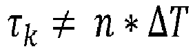
define

- Assume that ΔT = 5 ns and the test specification defines the following power delay profile:
Table 1: Power delay profile defined from test specification Tap k σk τk [ns] 1 σ 10 2 σ 2 6 3 σ 3 9 4 σ 4 15 - The power delay profile implemented in the
channel simulator 11 would then be:Table 2: Power delay profile implemented from channel simulator Tap k σk τmod,k [ns] 1 σ 10 2 σ 25 3 σ 310 4 σ 4 15 - Such a rounding of tap delay values is shown in
FIG. 4 . In the top part ofFIG. 4 , the original power delay profile of the channel simulation is shown. On the x-axis, the timing of the individual taps is shown, while on the y-axis, the respective power is depicted. Here, it can be seen that the timing of the individual taps does not lie on natural number multiples of the minimum time resolution ΔT of the device under test. - In the lower part of
FIG. 4 , the power delay profile after rounding is shown. It can clearly be seen that now the timing of all taps is set to a natural number multiples of the minimum time difference of events detectable by the device under test ΔT. - If rounding is performed as shown before, it may happen that two or more taps fall onto the same delay.
Those taps can then be combined to a single tap. - We will consider two examples here:
- 1. xk (t) is implemented as random process
- 2. xk (t) is implemented as a sum of sinusoids (SOS)
- Consider xk (t) being implemented as random process.
- Assume that after rounding K taps falls onto the same delay. Without loss of generality we number them with 1 ≤ k ≤ K, i.e.

- Those K taps will then be combined to a single tap with power σ 2 :

- Assume that ΔT = 5 ns and the test specification defines the following power delay profile:
Table 3: Power delay profile defined from test specification Tap k σk τk [ns] 1 σ 10 2 σ 24 3 σ 35 4 σ 4 6 5 σ 510 - After rounding of delays one obtains:
Table 4: Power delay profile after rounding of delays Tap k σk τmod,k [ns] 1 σ 10 2 σ 25 3 σ 35 4 σ 45 5 σ 510 - After combination of taps one obtains
Table: Power delay profile after combination of taps and implemented in channel simulator Tap k σk τ'k [ns] 1 σ 10 2 
5 3 σ 510 - And thus the impulse response is given as:

- Consider xk (t) being implemented as sum of sinusoids (SOS), i.e.


- Assume that after rounding K taps falls onto the same delay. Without loss of generality we number them with 1 ≤ k ≤ K, i.e.

- The original K taps, i.e.


- Such a combining of taps is shown in
FIG. 5 . While in the top part ofFIG. 5 , the original situation of the power delay profile before rounding and combining is shown. It can be seen that the tap with timing approximately 1.7 is rounded to a delay of 2. The taps with timings at 4.8, 5.1 and 5.3 are all rounded to a delay of 5 and combined into a single tap. The tap with a delay of 6.8 is rounded to a delay of 7. - Finally, in
FIG. 6 , an embodiment of the inventive measuring method is shown. In afirst step 100 input tap parameters are received. In asecond step 101, the input tap parameters are modified, so as to achieve the resulting tap parameters. In afinal step 102, a multipath propagation is simulated by modifying a first measuring signal, using a plurality of taps, defined by the tap parameters, resulting in the second measuring signal. - The invention is not limited to the examples and especially not to a measuring device comprising a signal generator. The channel simulator can operate as a stand alone measuring device as well. The characteristics of the exemplary embodiments can be implemented in any advantageous combination of the features claimed in the claims, described in the description or drawn in the drawings.
Claims (15)
- Measuring device (1) comprising a channel simulator (11), adapted to simulate multipath propagation by modifying a first measuring signal (13), using a plurality of taps (20, 21, 22) defined by tap parameters (τmod, hmod), resulting in a second measuring signal (14),
wherein the measuring device (1) comprises a parameter modifier (30), adapted to modify input tap parameters (τ, h), resulting in the tap parameters (τmod, hmod). - Measuring device according to claim 1,
wherein the parameter modifier (30) is adapted to modify the input tap parameters (τ, h) by rounding tap delay values (τ) and/or by combining taps (20, 21, 22), resulting in the tap parameters (τmod, hmod). - Measuring device according to claim 1 or 2,
wherein the measuring device (1) further comprises a signal generator (10), adapted to generate the first measuring signal (13), or a signal interface, adapted to receive the first measuring signal (13), and/or
wherein the measuring device (1) is adapted to provide the second measuring signal (14) to a device under test (12). - Measuring device according to claim 3,
wherein the parameter modifier (30) is adapted to modify the input tap parameters (τ, h) by rounding tap delay values (τ) and/or by combining taps (20, 21, 22), taking a capability of the device under test (12) defined by a capability parameter into account, resulting in the tap parameters (τmod, hmod). - Measuring device according to claim 4,
wherein the measuring device (1) further comprises a parameter storage (31), adapted to store the capability parameter of the device under test (12), and
wherein the parameter modifier (30) is adapted to read the capability parameter of the device under test (12) from the parameter storage (31). - Measuring device according to claim 4 or 5,
wherein the capability parameter of the device under test (12) is a minimal time difference (ΔT) of events in a reception signal, the device under test (12) can process. - Measuring device according to claim 6,
wherein the parameter modifier (30) is adapted to round tap delay values (τ) of the input tap parameters (τ, h) to natural number multiples of the minimal time difference (ΔT) of events in a reception signal, the device under test (12) can process. - Measuring device according to claim 7,
wherein if the rounding results in at least two taps (20, 21, 22) having an identical rounded tap delay value (τmod), the parameter modifier (30) is adapted to combine the at least two taps (20, 21, 22) of identical rounded tap delay value (τmod). - Measuring device according to claim 8,
wherein the parameter modifier (30) is adapted to combine the at least two taps (20, 21, 22) of identical rounded tap delay values (τmod), by adding scattering parameter (h) signals of the at least two taps (20, 21, 22) of identical delay values. - Measuring device according to any of the claims 1 to 9,
wherein the channel simulator (11) comprises a plurality of taps (20, 21, 22),
wherein each of the plurality of taps (20, 21, 22) comprises a delay element (201, 211, 221), each adapted to delay the first measuring signal (13) by a tap-specific tap delay value (τ1, τ2, τn), resulting in a delayed first measuring signal (203, 213, 223), for each of the taps (20, 21, 22),
wherein each of the taps (20, 21, 22) comprises a multiplier (202, 212, 222), adapted to multiply the delayed first measuring signal (203, 213, 223) of the respective tap (20, 21, 22) with a tap-specific scattering parameter signal (h1(t), h2(t), hn(t)), resulting in a tap output signal (204, 214, 224) for each of the taps (20, 21, 22), and
wherein the channel simulator (11) comprises an adder (23), adapted to add all tap output signals (204, 214, 224), resulting in the second measuring signal (14). - Measuring method for simulating a transmission of a first measuring signal (13) through a transmission channel, resulting in a second measuring signal (14), comprising the following steps:- receiving (100) input tap parameters (τ, h),- modifying (101) the input tap parameters (τ, h), resulting in tap parameters (τmod, hmod), and- simulating (102) multipath propagation by modifying the first measuring signal (13), using a plurality of taps (20, 21, 22) defined by the tap parameters (τmod, hmod), resulting in the second measuring signal (14).
- Measuring method according to claim 11,
wherein the method comprises modifying the input tap parameters (τ, h) by rounding tap delay values (τ) and/or by combining taps (20, 21, 22), resulting in the tap parameters (τmod, hmod). - Measuring device according to claim 12,
wherein the input tap parameters (τ, h) are modified by rounding tap delay values (τ) and/or by combining taps (20, 21, 22), taking a capability of a device under test (12), the second measuring signal (14) is provided to, defined by a capability parameter, into account, resulting in the tap parameters (τmod, hmod). - A computer program with program code means for performing all steps according to any of the claims 11 to 13 if the program is executed on a computer or a digital signal processor.
- A computer program product having a computer readable medium with stored program code means for performing all steps according to any of the claims 11 to 13 if the program is executed on a computer or a digital signal processor.
Priority Applications (1)
| Application Number | Priority Date | Filing Date | Title |
|---|---|---|---|
| EP18150922.5A EP3512130A1 (en) | 2018-01-10 | 2018-01-10 | Measuring device and method with efficient channel simulation |
Applications Claiming Priority (1)
| Application Number | Priority Date | Filing Date | Title |
|---|---|---|---|
| EP18150922.5A EP3512130A1 (en) | 2018-01-10 | 2018-01-10 | Measuring device and method with efficient channel simulation |
Publications (1)
| Publication Number | Publication Date |
|---|---|
| EP3512130A1 true EP3512130A1 (en) | 2019-07-17 |
Family
ID=60997307
Family Applications (1)
| Application Number | Title | Priority Date | Filing Date |
|---|---|---|---|
| EP18150922.5A Ceased EP3512130A1 (en) | 2018-01-10 | 2018-01-10 | Measuring device and method with efficient channel simulation |
Country Status (1)
| Country | Link |
|---|---|
| EP (1) | EP3512130A1 (en) |
Citations (2)
| Publication number | Priority date | Publication date | Assignee | Title |
|---|---|---|---|---|
| DE102009049415A1 (en) * | 2008-10-15 | 2010-04-22 | Deutsches Zentrum für Luft- und Raumfahrt e.V. | Method for reducing channel model i.e. time variant tapped-delay-line-model, utilized for simulating signal transmission channel between transmitter and receiver, involves optimizing resultant function based on folding |
| US7852912B2 (en) | 2005-03-25 | 2010-12-14 | Agilent Technologies, Inc. | Direct determination equalizer system |
-
2018
- 2018-01-10 EP EP18150922.5A patent/EP3512130A1/en not_active Ceased
Patent Citations (2)
| Publication number | Priority date | Publication date | Assignee | Title |
|---|---|---|---|---|
| US7852912B2 (en) | 2005-03-25 | 2010-12-14 | Agilent Technologies, Inc. | Direct determination equalizer system |
| DE102009049415A1 (en) * | 2008-10-15 | 2010-04-22 | Deutsches Zentrum für Luft- und Raumfahrt e.V. | Method for reducing channel model i.e. time variant tapped-delay-line-model, utilized for simulating signal transmission channel between transmitter and receiver, involves optimizing resultant function based on folding |
Non-Patent Citations (3)
| Title |
|---|
| "3 rd Generation Partnership Project; Technical Specification Group Radio Access Network; Study on channel model for frequencies from 0.5 to 100 GHz (Release 14)", 5 January 2018 (2018-01-05), XP051424492, Retrieved from the Internet <URL:http://www.3gpp.org/ftp/3guInternal/3GPP_ultimate_versions_to_be_transposed/duplicatesNotSentToDpc/38901-e30.doc> [retrieved on 20180105] * |
| SILVA J C ET AL: "Conversion of reference tapped delay line channel models to discrete time channel models [UMTS]", VEHICULAR TECHNOLOGY CONFERENCE, 2003. VTC 2003-FALL. 2003 IEEE 58TH ORLANDO, FL, USA 6-9 OCT. 2003; [IEEE VEHICULAR TECHNOLGY CONFERENCE], PISCATAWAY, NJ, USA,IEEE, US, 6 October 2003 (2003-10-06), pages 128 - 132Vol.1, XP010700814, ISBN: 978-0-7803-7954-1, DOI: 10.1109/VETECF.2003.1284992 * |
| SPIRENT COMMUNICATIONS: "Channel Modelling for RAN4 RRM and Demodulation Testing", vol. RAN WG4, no. Berlin,Germany; 20170821 - 20170825, 20 August 2017 (2017-08-20), XP051320577, Retrieved from the Internet <URL:http://www.3gpp.org/ftp/Meetings_3GPP_SYNC/RAN4/Docs/> [retrieved on 20170820] * |
Similar Documents
| Publication | Publication Date | Title |
|---|---|---|
| Yip et al. | A simulation model for Nakagami-m fading channels, m< 1 | |
| US20150054687A1 (en) | Method for over-the-air measurement signal generation | |
| US6278964B1 (en) | Hot carrier effect simulation for integrated circuits | |
| CN109361378B (en) | Verification platform and verification method for asynchronous clock of SOC (System on chip) | |
| US9917755B1 (en) | Providing fast radio-frequency delay measurements for envelope tracking | |
| US7778167B2 (en) | Simulating packet delay variation using step-target delay method | |
| US20160072595A1 (en) | Signal generating device with integrated fading generating unit and signal generating method | |
| EP3751382A1 (en) | Sequence signal generator and sequence signal generation method | |
| US20250310229A1 (en) | Circuit and Method for Timestamp Jitter Reduction | |
| Jiang et al. | A novel simulation model for nonstationary rice fading channels | |
| Wolfson et al. | Improving IGM temperature constraints using wavelet analysis on high-redshift quasars | |
| US9331681B2 (en) | System and method for gaussian random noise generation | |
| CN117669441B (en) | Interface timing inspection method, device and electronic device for design under test | |
| US9294324B2 (en) | Signal generator and signal generation method with cyclic prefix generation | |
| US10680723B1 (en) | Measuring device and method with efficient channel simulation | |
| EP2713572A2 (en) | Method, device, and system for frequency offset estimation and channel estimation | |
| US7080292B2 (en) | Method for testing jitter tolerance of high speed receivers | |
| US20240356661A1 (en) | Method of generating simulated multipath fading channel data | |
| Alimohammad et al. | A compact architecture for simulation of spatio-temporally correlated MIMO fading channels | |
| US20080225746A1 (en) | Method and system for generating packet delay variation with a uniform distribution | |
| Ruiz-García et al. | SDR-based channel emulator for vehicular communications | |
| Bidaj et al. | Jitter definition, measurement, generation, analysis, and decomposition | |
| US20200036486A1 (en) | Signal generator and frequency characteristic display method using signal generator | |
| CN115694768B (en) | Intermodulation interference analysis method, intermodulation interference analysis device, electronic equipment and readable storage medium | |
| US20170311186A1 (en) | Methods, systems and computer readable media for simulating per user equipment (ue) slow and fast signal fading for testing air interface devices |
Legal Events
| Date | Code | Title | Description |
|---|---|---|---|
| STAA | Information on the status of an ep patent application or granted ep patent |
Free format text: STATUS: EXAMINATION IS IN PROGRESS |
|
| PUAI | Public reference made under article 153(3) epc to a published international application that has entered the european phase |
Free format text: ORIGINAL CODE: 0009012 |
|
| 17P | Request for examination filed |
Effective date: 20180827 |
|
| AK | Designated contracting states |
Kind code of ref document: A1 Designated state(s): AL AT BE BG CH CY CZ DE DK EE ES FI FR GB GR HR HU IE IS IT LI LT LU LV MC MK MT NL NO PL PT RO RS SE SI SK SM TR |
|
| AX | Request for extension of the european patent |
Extension state: BA ME |
|
| STAA | Information on the status of an ep patent application or granted ep patent |
Free format text: STATUS: THE APPLICATION HAS BEEN REFUSED |
|
| 18R | Application refused |
Effective date: 20191210 |