EP3512066A1 - Charging circuit, terminal, and charging system - Google Patents
Charging circuit, terminal, and charging system Download PDFInfo
- Publication number
- EP3512066A1 EP3512066A1 EP17852213.2A EP17852213A EP3512066A1 EP 3512066 A1 EP3512066 A1 EP 3512066A1 EP 17852213 A EP17852213 A EP 17852213A EP 3512066 A1 EP3512066 A1 EP 3512066A1
- Authority
- EP
- European Patent Office
- Prior art keywords
- circuit
- charging
- current
- battery
- adjustment
- Prior art date
- Legal status (The legal status is an assumption and is not a legal conclusion. Google has not performed a legal analysis and makes no representation as to the accuracy of the status listed.)
- Granted
Links
Images



Classifications
-
- H—ELECTRICITY
- H02—GENERATION; CONVERSION OR DISTRIBUTION OF ELECTRIC POWER
- H02J—ELECTRIC POWER NETWORKS; CIRCUIT ARRANGEMENTS OR SYSTEMS FOR SUPPLYING OR DISTRIBUTING ELECTRIC POWER; SYSTEMS FOR STORING ELECTRIC ENERGY
- H02J7/00—Circuit arrangements for charging or discharging batteries or for supplying loads from batteries
- H02J7/60—Circuit arrangements for charging or discharging batteries or for supplying loads from batteries including safety or protection arrangements
- H02J7/685—Circuit arrangements for charging or discharging batteries or for supplying loads from batteries including safety or protection arrangements using connection detecting circuits
-
- H—ELECTRICITY
- H02—GENERATION; CONVERSION OR DISTRIBUTION OF ELECTRIC POWER
- H02J—ELECTRIC POWER NETWORKS; CIRCUIT ARRANGEMENTS OR SYSTEMS FOR SUPPLYING OR DISTRIBUTING ELECTRIC POWER; SYSTEMS FOR STORING ELECTRIC ENERGY
- H02J7/00—Circuit arrangements for charging or discharging batteries or for supplying loads from batteries
- H02J7/865—Battery or charger load switching, e.g. concurrent charging and load supply
-
- H—ELECTRICITY
- H02—GENERATION; CONVERSION OR DISTRIBUTION OF ELECTRIC POWER
- H02J—ELECTRIC POWER NETWORKS; CIRCUIT ARRANGEMENTS OR SYSTEMS FOR SUPPLYING OR DISTRIBUTING ELECTRIC POWER; SYSTEMS FOR STORING ELECTRIC ENERGY
- H02J7/00—Circuit arrangements for charging or discharging batteries or for supplying loads from batteries
-
- H—ELECTRICITY
- H02—GENERATION; CONVERSION OR DISTRIBUTION OF ELECTRIC POWER
- H02J—ELECTRIC POWER NETWORKS; CIRCUIT ARRANGEMENTS OR SYSTEMS FOR SUPPLYING OR DISTRIBUTING ELECTRIC POWER; SYSTEMS FOR STORING ELECTRIC ENERGY
- H02J7/00—Circuit arrangements for charging or discharging batteries or for supplying loads from batteries
- H02J7/60—Circuit arrangements for charging or discharging batteries or for supplying loads from batteries including safety or protection arrangements
-
- H—ELECTRICITY
- H02—GENERATION; CONVERSION OR DISTRIBUTION OF ELECTRIC POWER
- H02J—ELECTRIC POWER NETWORKS; CIRCUIT ARRANGEMENTS OR SYSTEMS FOR SUPPLYING OR DISTRIBUTING ELECTRIC POWER; SYSTEMS FOR STORING ELECTRIC ENERGY
- H02J7/00—Circuit arrangements for charging or discharging batteries or for supplying loads from batteries
- H02J7/60—Circuit arrangements for charging or discharging batteries or for supplying loads from batteries including safety or protection arrangements
- H02J7/64—Circuit arrangements for charging or discharging batteries or for supplying loads from batteries including safety or protection arrangements against overvoltage
-
- H—ELECTRICITY
- H02—GENERATION; CONVERSION OR DISTRIBUTION OF ELECTRIC POWER
- H02J—ELECTRIC POWER NETWORKS; CIRCUIT ARRANGEMENTS OR SYSTEMS FOR SUPPLYING OR DISTRIBUTING ELECTRIC POWER; SYSTEMS FOR STORING ELECTRIC ENERGY
- H02J7/00—Circuit arrangements for charging or discharging batteries or for supplying loads from batteries
- H02J7/60—Circuit arrangements for charging or discharging batteries or for supplying loads from batteries including safety or protection arrangements
- H02J7/663—Circuit arrangements for charging or discharging batteries or for supplying loads from batteries including safety or protection arrangements using battery or load disconnect circuits
-
- H—ELECTRICITY
- H02—GENERATION; CONVERSION OR DISTRIBUTION OF ELECTRIC POWER
- H02J—ELECTRIC POWER NETWORKS; CIRCUIT ARRANGEMENTS OR SYSTEMS FOR SUPPLYING OR DISTRIBUTING ELECTRIC POWER; SYSTEMS FOR STORING ELECTRIC ENERGY
- H02J7/00—Circuit arrangements for charging or discharging batteries or for supplying loads from batteries
- H02J7/90—Regulation of charging or discharging current or voltage
-
- H—ELECTRICITY
- H02—GENERATION; CONVERSION OR DISTRIBUTION OF ELECTRIC POWER
- H02J—ELECTRIC POWER NETWORKS; CIRCUIT ARRANGEMENTS OR SYSTEMS FOR SUPPLYING OR DISTRIBUTING ELECTRIC POWER; SYSTEMS FOR STORING ELECTRIC ENERGY
- H02J7/00—Circuit arrangements for charging or discharging batteries or for supplying loads from batteries
- H02J7/60—Circuit arrangements for charging or discharging batteries or for supplying loads from batteries including safety or protection arrangements
- H02J7/62—Circuit arrangements for charging or discharging batteries or for supplying loads from batteries including safety or protection arrangements against overcurrent
Definitions
- the present invention relates to charging technologies, and in particular, to a charging circuit, a terminal, and a charging system.
- a current in a charging circuit of a terminal may be converted, when being input into a battery, to a higher charging current (which cannot exceed a maximum safe charging current that the battery can bear or a safe charging current that does not damage a battery life).
- a higher charging current which cannot exceed a maximum safe charging current that the battery can bear or a safe charging current that does not damage a battery life.
- an electronic device charging control apparatus In a process of charging a battery in an electronic device by the electronic device charging control apparatus, a power adapter first charges the battery by means of constant-voltage output. After receiving a fast charging instruction command sent by a charging control module, the power adapter adjusts an output voltage according to a battery voltage fed back by the charging control module, and adjusts, when the output voltage meets a fast charging voltage condition preset by the charging control module, an output current and the output voltage according to a fast charging current value and a fast charging voltage value, so as to perform fast charging on the battery.
- the charging control module introduces a direct current from the power adapter to charge the battery.
- the power adapter further adjusts the output current in real time according to the output voltage of the power adapter and the battery voltage, so that fast charging of the battery is implemented by adjusting the output current and the output voltage of the power adapter.
- the power adapter obtains, in a real-time communication manner, feedback information of a charging current and a charging voltage from the charging control module in the electronic device, and performs real-time adjustment in the power adapter.
- the technical solution is applicable to a scenario in which a requirement on real-time adjustment is relatively low in a charging process.
- a charging scenario in which a requirement on real-time adjustment is relatively high if a current required by a terminal load suddenly decreases and output adjustment of the power adapter is not performed in time, the charging current flowing to the battery suddenly increases. This easily causes a potential safety threat to a charging circuit and a charged battery in the electronic device.
- Embodiments of the present invention provide a charging circuit, a terminal, and a charging system, so that in a scenario in which a charging current suddenly increases during charging because a current consumed by a terminal load decreases and an output current from a power adapter cannot be adjusted in time, the charging current can be adjusted and controlled, so as to prevent damage to a battery or the charging circuit due to an excessively high charging current, thereby ensuring charging safety.
- a first aspect of the present invention provides a charging circuit.
- the charging circuit is separately connected to a charger, a terminal load, and a battery, so that when charging the battery by using the charging circuit, the charger can further supply power to the terminal load.
- the charging circuit includes a first adjustment circuit, a current detection circuit, a voltage detection circuit, and a control circuit.
- a first end of the first adjustment circuit is connected to the charger; a second end of the first adjustment circuit is connected to a positive electrode of the battery; the second end of the first adjustment circuit is further connected to the terminal load; and a third end of the first adjustment circuit is connected to the control circuit.
- a negative electrode of the battery is connected to the charger.
- the current detection circuit is connected in series between the second end of the first adjustment circuit and the positive electrode of the battery, or is connected in series between the negative electrode of the battery and the charger.
- a detection end of the voltage detection circuit is connected in parallel at the positive and negative electrodes of the battery, and an output end of the voltage detection circuit is further connected to the control circuit.
- the voltage detection circuit is configured to: detect voltages at two ends of the battery to obtain a voltage value of the battery, and send the voltage value of the battery to the control circuit.
- the current detection circuit is configured to: detect a current of the charging circuit to obtain a current value of the charging circuit, and send the current value to the first adjustment circuit.
- the control circuit is configured to: determine a charging mode according to the voltage value of the battery, and determine a current upper limit value according to the charging mode.
- the first adjustment circuit is configured to obtain the current value and the current upper limit value; and is further configured to: compare the current value with the current upper limit value to determine whether the current value is greater than the current upper limit value, and when the current value is greater than the current upper limit value, adjust upward an impedance of the first adjustment circuit according to the current value.
- an objective of adjusting upward the impedance of the first adjustment circuit is to decrease a charging current, that is, a larger current value indicates a higher adjusted impedance of the first adjustment circuit.
- the current detection circuit is further connected to the control circuit.
- the current detection circuit is further configured to send the current value to the control circuit.
- the control circuit is configured to: determine whether the current value is greater than the current upper limit value; and when the current value is greater than the current upper limit value, send an adjustment instruction to the charger, so that the charger adjusts downward output power, an output current, or an output voltage.
- control circuit is further configured to determine a current lower limit value according to the charging mode.
- the first adjustment circuit is further configured to: obtain the current lower limit value; compare the current value with the current lower limit value to determine whether the current value is less than the current lower limit value; and when the current value is less than the current lower limit value, adjust downward the impedance of the first adjustment circuit according to the current value.
- the impedance of the first adjustment circuit needs to be adjusted downward to increase the charging current.
- the charging circuit further includes a protection circuit.
- the protection circuit is connected in series between the charger and the first end of the first adjustment circuit.
- the control circuit is further connected to the protection circuit.
- the control circuit is further configured to: determine a protection trigger condition according to the charging mode; and send the protection trigger condition to the protection circuit.
- the protection circuit is configured to: detect the output current of the charger to determine an output current value; determine whether the output current value meets the protection trigger condition; and when the output current value meets the protection trigger condition, open a switch to interrupt charging.
- the protection trigger condition includes a current protection trigger condition and a voltage protection trigger condition. That is, the protection circuit is specifically configured to: detect the output current of the charger to determine the output current value; determine whether the output current value is greater than the current protection trigger condition; and when the output current value is greater than the current protection trigger condition, open the switch to interrupt charging.
- the protection circuit may detect whether a voltage of the battery is an overvoltage and detect whether the output voltage of the charger is an overvoltage. Therefore, the voltage protection trigger condition includes a battery voltage protection trigger condition and a charger voltage trigger protection condition. Specifically, the voltage of the battery corresponds to the battery voltage protection trigger condition, and the output voltage of the charger corresponds to the charger voltage protection trigger condition.
- the protection circuit is further connected to the voltage detection circuit to obtain the voltage value of the battery.
- the protection circuit is further configured to: determine whether the voltage value of the battery is greater than the battery voltage protection trigger condition; and when the voltage value of the battery is greater than the battery voltage protection trigger condition, open the switch to interrupt charging.
- the protection circuit is further configured to: detect the output voltage of the charger to obtain an output voltage value; determine whether the output voltage value is greater than the charger voltage protection trigger condition; and when the output voltage value is greater than the charger voltage protection trigger condition, open the switch to interrupt charging.
- the charging circuit further includes a communication circuit.
- the communication circuit is connected to the control circuit.
- the control circuit is further configured to send the charging mode to the communication circuit.
- the communication circuit is configured to send the charging mode to the charger, so that the charger performs charging according to the charging mode.
- the communication circuit may be connected to the charger by using a connection cable or may interact with the charger in a wireless manner to perform information transfer.
- the charging circuit further includes a second adjustment circuit.
- the second adjustment circuit is connected in series between the second end of the first adjustment circuit and the positive electrode of the battery. It should be noted that if the current detection circuit is connected in series between the first adjustment circuit and the positive electrode of the battery, alternatively, the second adjustment circuit may be connected in series between the positive electrode of the battery and the current detection circuit, or may be connected in series between the second end of the first adjustment circuit and the current detection circuit.
- the second adjustment circuit is further connected to the control circuit.
- the control circuit is further configured to determine an adjustment threshold of the second adjustment circuit according to the charging mode.
- the second adjustment circuit is configured to adjust an impedance of the second adjustment circuit according to the current value and the adjustment threshold of the second adjustment circuit.
- the adjustment threshold of the second adjustment circuit also includes an upper threshold and a lower threshold. It may be understood that when the current value is greater than the upper threshold, the impedance of the second adjustment circuit is adjusted upward to decrease the charging current; or when the current value is less than the lower threshold, the impedance of the second adjustment circuit is adjusted downward to increase the charging current.
- the charging circuit further includes a third adjustment circuit and a current monitoring circuit.
- the third adjustment circuit and the current monitoring circuit are connected in series between the second end of the first adjustment circuit and the terminal load.
- the current monitoring circuit is configured to: monitor a decrease amplitude of a current of the terminal load; and when the decrease amplitude exceeds a preset threshold, send an adjustment instruction to the third adjustment circuit.
- the third adjustment circuit is configured to adjust upward an impedance of the third adjustment circuit according to the adjustment instruction.
- the third adjustment circuit is further configured to restore, after preset duration, the impedance of the third adjustment circuit to a state before the impedance is adjusted upward.
- the third adjustment circuit is further configured to adjust downward the impedance of the third adjustment circuit after preset duration.
- the preset duration is greater than current adjustment duration of the charger. After the current required by the terminal load decreases, the current of the charging circuit increases. Therefore, in this case, the control circuit sends, to the charger, an instruction for decreasing the output current. After receiving the instruction, the charger has the current adjustment duration, that is, the charger adjusts the current to a target value in the current adjustment duration.
- a second aspect of the present invention discloses another charging circuit.
- the charging circuit is separately connected to a charger, a terminal load, and a battery, and the charging circuit includes a first adjustment circuit, a current detection circuit, a voltage detection circuit, and a control circuit.
- the adjustment circuit in the charging circuit is deployed in a branch circuit.
- a first end of the first adjustment circuit is connected to the charger; the first end of the first adjustment circuit is further connected to the terminal load; a second end of the first adjustment circuit is connected to a positive electrode of the battery; and a third end of the first adjustment circuit is connected to the control circuit.
- a negative electrode of the battery is connected to the charger.
- the current detection circuit is connected in series between the second end of the first adjustment circuit and the positive electrode of the battery, or is connected in series between the negative electrode of the battery and the charger.
- a detection end of the voltage detection circuit is connected in parallel at the positive and negative electrodes of the battery, and an output end of the voltage detection circuit is connected to the control circuit.
- the voltage detection circuit is configured to: detect voltages at two ends of the battery to obtain a voltage value of the battery, and send the voltage value of the battery to the control circuit.
- the current detection circuit is configured to: detect a current of the charging circuit to obtain a current value of the charging circuit, and send the current value to the first adjustment circuit.
- the control circuit is configured to: determine a charging mode according to the voltage value of the battery, and determine a current upper limit value according to the charging mode.
- the first adjustment circuit is configured to obtain the current value and the current upper limit value; and is further configured to: compare the current value with the current upper limit value to determine whether the current value is greater than the current upper limit value, and when the current value is greater than the current upper limit value, adjust upward an impedance of the first adjustment circuit according to the current value.
- the current detection circuit is further connected to the control circuit.
- the current detection circuit is further configured to send the current value to the control circuit.
- the control circuit is configured to: determine whether the current value is greater than the current upper limit value; and when the current value is greater than the current upper limit value, send an adjustment instruction to the charger, so that the charger adjusts downward output power, an output current, or an output voltage.
- the charger adjusts downward the output current. In this case, a charging current decreases. To ensure charging efficiency, the impedance of the first adjustment circuit needs to be adjusted downward. Details are as follows:
- the control circuit is further configured to determine a current lower limit value according to the charging mode.
- the first adjustment circuit is configured to: obtain the current lower limit value; compare the current value with the current lower limit value to determine whether the current value is less than the current lower limit value; and when the current value is less than the current lower limit value, adjust downward the impedance of the adjustment circuit according to the current value.
- the charging circuit further includes a protection circuit.
- the protection circuit is connected in series between the charger and the first end of the first adjustment circuit.
- the control circuit is further connected to the protection circuit.
- the control circuit is further configured to: determine a protection trigger condition according to the charging mode; and send the protection trigger condition to the protection circuit.
- the protection circuit is configured to: detect the output current of the charger to determine an output current value; determine whether the output current value meets the protection trigger condition; and when the output current value meets the protection trigger condition, open a switch to interrupt charging.
- the protection trigger condition includes both a current trigger protection condition and a voltage trigger protection condition.
- the protection circuit is configured to: determine whether the output current value is greater than the current protection trigger condition; and when the output current value is greater than the current protection trigger condition, open the switch to interrupt charging.
- the protection circuit may detect whether a voltage of the battery is an overvoltage and detect whether an output voltage of the charger is an overvoltage. Therefore, the voltage protection trigger condition includes a battery voltage protection trigger condition and a charger voltage trigger protection condition. Specifically, the voltage of the battery corresponds to the battery voltage protection trigger condition, and the output voltage of the charger corresponds to the charger voltage protection trigger condition.
- the protection circuit is further connected to the voltage detection circuit to obtain the voltage value of the battery.
- the protection circuit is further configured to: determine whether the voltage value of the battery is greater than the battery voltage protection trigger condition; and when the voltage value of the battery is greater than the battery voltage protection trigger condition, open the switch to interrupt charging.
- the protection circuit is further configured to: detect the output voltage of the charger to obtain an output voltage value; determine whether the output voltage value is greater than the charger voltage protection trigger condition; and when the output voltage value is greater than the charger voltage protection trigger condition, open the switch to interrupt charging.
- the control circuit needs to interact with the charger to control the charger to adjust the output power, the output voltage, or the output current. Therefore, the charging circuit further includes a communication circuit.
- the communication circuit is connected to the control circuit.
- the control circuit is further configured to send the charging mode to the communication circuit.
- the communication circuit is configured to send the charging mode to the charger, so that the charger performs charging according to the charging mode.
- the communication circuit may be connected to the charger by using a connection cable to perform information transfer.
- the communication circuit may interact with the charger in a wireless manner.
- the charging circuit further includes a second adjustment circuit and a current monitoring circuit.
- the second adjustment circuit and the current monitoring circuit are connected in series between the first end of the first adjustment circuit and the terminal load.
- the current monitoring circuit is configured to: monitor a decrease amplitude of a current of the terminal load; and when the decrease amplitude exceeds a preset threshold, send an adjustment instruction to the second adjustment circuit.
- the second adjustment circuit is configured to adjust upward an impedance of the second adjustment circuit according to the adjustment instruction.
- the second adjustment circuit is further configured to restore, after preset duration, the impedance of the second adjustment circuit to a state before the impedance is adjusted upward.
- a third aspect of the present invention discloses another charging circuit.
- the charging circuit is separately connected to a charger, a terminal load, and a battery, and the charging circuit includes an adjustment circuit and a current monitoring circuit.
- a first end of the adjustment circuit is connected to the charger; a second end of the adjustment circuit is connected to a first end of the current monitoring circuit; and a second end of the current monitoring circuit is connected to the terminal load.
- a positive electrode of the charger is connected to a positive electrode of the battery; and a negative electrode of the charger is connected to a negative electrode of the battery.
- the current monitoring circuit is configured to: monitor a decrease amplitude of a current of the terminal load; and when the decrease amplitude exceeds a preset threshold, send an adjustment instruction to the adjustment circuit.
- the adjustment circuit is configured to adjust upward an impedance of the adjustment circuit according to the adjustment instruction.
- the adjustment circuit is further configured to: after preset duration for which the impedance of the adjustment circuit is adjusted upward, restore the impedance of the adjustment circuit to a state before the impedance is adjusted upward.
- the charging circuit further includes a current detection circuit, a voltage detection circuit, a control circuit, and a protection circuit.
- the protection circuit is connected in series between the charger and the positive electrode of the battery.
- the current detection circuit is connected in series between the protection circuit and the positive electrode of the battery, or is connected in series between the negative electrode of the battery and the charger.
- a detection end of the voltage detection circuit is connected in parallel at the positive and negative electrodes of the battery.
- the control circuit is connected to the current detection circuit, is further connected to an output end of the voltage detection circuit, and is further connected to the protection circuit.
- the voltage detection circuit is configured to: detect voltages at two ends of the battery to obtain a voltage value of the battery, and send the voltage value of the battery to the control circuit.
- the current detection circuit is configured to: detect a current of the charging circuit to obtain a current value of the charging circuit, and send the current value to the protection circuit.
- the control circuit is configured to: determine a charging mode according to the voltage value of the battery, and determine a protection trigger condition according to the charging mode.
- the protection circuit is configured to: detect an output current of the charger to determine an output current value; determine whether the output current value meets the protection trigger condition; and when the output current value meets the protection trigger condition, open a switch to interrupt charging.
- the protection circuit may detect whether a voltage of the battery is an overvoltage and detect whether an output voltage of the charger is an overvoltage. Therefore, the voltage protection trigger condition includes a battery voltage protection trigger condition and a charger voltage trigger protection condition. Specifically, the voltage of the battery corresponds to the battery voltage protection trigger condition, and the output voltage of the charger corresponds to the charger voltage protection trigger condition.
- the protection circuit is further connected to the voltage detection circuit to obtain the voltage value of the battery.
- the protection circuit is further configured to: determine whether the voltage value of the battery is greater than the battery voltage protection trigger condition; and when the voltage value of the battery is greater than the battery voltage protection trigger condition, open the switch to interrupt charging.
- the protection circuit is further configured to: detect an output voltage of the charger to obtain an output voltage value; determine whether the output voltage value is greater than the charger voltage protection trigger condition; and when the output voltage value is greater than the charger voltage protection trigger condition, open the switch to interrupt charging.
- a fourth aspect of the present invention further discloses a terminal.
- the terminal includes the charging circuit according to any one of the first aspect to the third aspect.
- a fifth aspect of the present invention discloses a charging system.
- the charging system includes a charger, a connection cable, and the terminal according to the fourth aspect.
- the charger is connected to the terminal by using the connection cable.
- a sixth aspect of the present invention discloses a charging method.
- the method includes: detecting a charging current to obtain a charging current value; detecting a voltage of a battery to obtain a voltage value of the battery; determining a charging mode matching the voltage value of the battery; determining a current upper limit value according to the charging mode; and when the charging current value is greater than the current upper limit value, adjusting upward an impedance of a charging path according to the charging current value.
- the method further includes: determining a current lower limit value according to the charging mode; and when the charging current value is less than the current lower limit value, adjusting downward the impedance of the charging path according to the charging current value.
- the charging circuit is separately connected to the charger, the terminal load, and the battery.
- the charging circuit includes the first adjustment circuit, the current detection circuit, the voltage detection circuit, and the control circuit.
- the first end of the first adjustment circuit is connected to the charger; the second end of the first adjustment circuit is connected to the positive electrode of the battery; the second end of the first adjustment circuit is further connected to the terminal load; and the third end of the first adjustment circuit is connected to the control circuit.
- the negative electrode of the battery is connected to the charger.
- the current detection circuit is connected in series between the second end of the first adjustment circuit and the positive electrode of the battery, or is connected in series between the negative electrode of the battery and the charger.
- the detection end of the voltage detection circuit is connected in parallel at the positive and negative electrodes of the battery.
- the output end of the voltage detection circuit is connected to the control circuit.
- the voltage detection circuit is configured to: detect voltages at two ends of the battery to obtain a voltage value of the battery, and send the voltage value of the battery to the control circuit.
- the current detection circuit is configured to: detect a current of the charging circuit to obtain a current value of the charging circuit, and send the current value to the first adjustment circuit.
- the control circuit is configured to: determine a charging mode according to the voltage value of the battery, and determine a current upper limit value according to the charging mode.
- the first adjustment circuit is configured to obtain the current value and the current upper limit value; and is further configured to: compare the current value with the current upper limit value to determine whether the current value is greater than the current upper limit value, and when the current value is greater than the current upper limit value, adjust upward an impedance of the first adjustment circuit according to the current value.
- the charging circuit provided in the present invention can adjust, when a charging current suddenly increases, the charging current, so as to prevent damage to the charging circuit and the battery due to an excessively high charging current. Further, after the charger adjusts downward an output current, the charging current decreases. In this case, the impedance of the adjustment circuit in the charging circuit may be adjusted downward to increase the charging current, so as to ensure charging efficiency.
- terminals for example, electronic devices such as a smartphone, a wearable device, and a tablet computer
- functions of terminals are becoming stronger, and users can perform office work and entertainment by using the terminals, so that the terminals have become an indispensable part in people's daily life.
- an endurance capability of a terminal is limited, and a user needs to continuously charge the terminal.
- a current in a charging circuit of a terminal may be converted, when being input into a battery, to a higher charging current (which cannot exceed a maximum safe charging current that the battery can bear or a safe charging current that does not damage a battery life).
- a higher charging current which cannot exceed a maximum safe charging current that the battery can bear or a safe charging current that does not damage a battery life.
- an electronic device charging control apparatus In a process of charging a battery in an electronic device by the electronic device charging control apparatus, a power adapter first charges the battery by means of constant-voltage output. After receiving a fast charging instruction command sent by a charging control module, the power adapter adjusts an output voltage according to a battery voltage fed back by the charging control module, and adjusts, when the output voltage meets a fast charging voltage condition preset by the charging control module, an output current and the output voltage according to a fast charging current value and a fast charging voltage value, so as to perform fast charging on the battery.
- the charging control module introduces a direct current from the power adapter to charge the battery.
- the power adapter further adjusts the output current in real time according to the output voltage of the power adapter and the battery voltage, so that fast charging of the battery is implemented by adjusting the output current and the output voltage of the power adapter.
- the power adapter obtains, in a real-time communication manner, feedback information of a charging current and a charging voltage from the charging control module in the electronic device, and performs real-time adjustment in the power adapter.
- the technical solution is applicable to a scenario in which a requirement on real-time adjustment is relatively low in a charging process.
- a charging scenario in which a requirement on real-time adjustment is relatively high if a current required by a terminal load suddenly decreases and output adjustment of the power adapter is not performed in time, the charging current flowing to the battery suddenly increases. This easily causes a potential safety threat to a charging circuit and a charged battery in the electronic device.
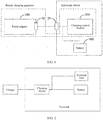
- FIG. 1 is a charging system according to an embodiment of the present invention.
- the charging system provided in the present invention, when a charging current suddenly increases, the charging current can be adjusted, so as to prevent damage to a charging circuit and a battery due to an excessively high charging current.
- the charging system includes a terminal, a charger, and a connection cable.
- the terminal is connected to the charger by using the connection cable.
- the terminal may be an electronic device such as a smartphone, a tablet computer, an intelligent wearable device, or a computer.
- the terminal includes a terminal load, the battery, and the charging circuit of the terminal.
- the charging circuit is separately connected to the charger, the terminal load, and the battery.
- the charging circuit is configured to: detect voltages at two ends of the battery to obtain a voltage value of the battery, determine a charging mode according to the voltage value of the battery, and determine a current upper limit value according to the charging mode; and is further configured to: detect a current of the charging circuit to obtain a current value of the charging circuit, determine whether the current value is greater than the current upper limit value, and when the current value is greater than the current upper limit value, adjust upward an impedance of the adjustment circuit according to the current value.
- the charging circuit is further configured to: determine a current lower limit value according to the charging mode; determine whether the current value is less than the current lower limit value; and when the current value is less than the current lower limit value, adjust downward the impedance of the adjustment circuit according to the current value.
- an impedance of the charging circuit can be adjusted in a charging process to decrease the charging current, so as to prevent damage to the battery or the charging circuit due to an excessively high charging current, and further ensure charging safety. Further, after the charger adjusts downward the output current, the charging current decreases. In this case, the impedance of the adjustment circuit in the charging circuit may be adjusted downward to increase the charging current, so as to ensure charging efficiency.
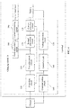
- FIG. 3 shows a specific implementation of a charging circuit.
- the charging circuit 10 is separately connected to a charger, a terminal load, and a battery, so that when charging the battery by using the charging circuit, the charger can further supply power to the terminal load.
- the charging circuit 10 includes a first adjustment circuit 110, a current detection circuit 120, a voltage detection circuit 130, and a control circuit 140.
- the first adjustment circuit 110 is connected to a positive electrode of the charger; a second end of the first adjustment circuit 110 is connected to a first end of the current detection circuit 120; the second end of the first adjustment circuit 110 is further connected to the terminal load; and a third end of the first adjustment circuit 110 is connected to the control circuit 140.
- the first adjustment circuit may be a MOS transistor (that is, a metal oxide semiconductor field effect transistor which may be also referred to as a metal insulator transistor). It may be understood that the MOS transistor has three ports. The three ports are respectively a G electrode, an S electrode, and a D electrode.
- the first end may be the S electrode
- the second end may be the D electrode
- the third end may be the G electrode.
- the first end may be the D electrode
- the second end may be the P electrode
- the third end may be the G electrode.
- the first adjustment circuit may adjust an impedance of the first adjustment circuit by adjusting drive voltages at G and S ends.
- a second end of the current detection circuit 120 is connected to a positive electrode of the battery; and a negative electrode of the battery is connected to the charger.
- the current detection circuit 120 is connected in series between the negative electrode of the battery and the charger; and a detection end of the voltage detection circuit 130 is connected in parallel at the positive and negative electrodes of the battery.
- one end of the voltage detection circuit 130 is connected to the positive electrode of the battery, and another end is connected to the negative electrode of the battery.
- An output end of the voltage detection circuit 130 is further connected to the control circuit 140. It may be understood according to the connection manner that the voltage detection circuit 130 is configured to: detect voltages at two ends of the battery to obtain a voltage value of the battery, and send the voltage value of the battery to the control circuit 140.
- the current detection circuit 120 is configured to: detect a current of the charging circuit to obtain a current value of the charging circuit, and send the current value to the first adjustment circuit 110.
- the control circuit 140 is configured to: determine a charging mode according to the voltage value of the battery, and determine a current upper limit value according to the charging mode.
- the control circuit 140 searches the following table according to the voltage value of the battery to determine the charging mode. Charging mode Battery voltage value Not charged ⁇ 2.8 V 8 A fast charging 2.8-4.2 V 6 A fast charging 4.2-4.3 V 4 A fast charging 4.3-4.4 V Charging completed Battery voltage: 4.4 V; charging current: less than 0.03 A
- control circuit 140 searches the following table according to the charging mode to determine the current upper limit value.
- Charging mode Current upper limit value and current lower limit value Adjustment manner 8 A fast charging Greater than 8.3 A or less than 7.7 A Constant-current control 6 A fast charging Greater than 6.3 A or less than 5.7 A Constant-current control 4 A fast charging Greater than 4.3 A or less than 3.7 A Constant-current control 4.4 V constant-voltage charging A battery voltage reaches 4.4 V Not adjusted
- the first adjustment circuit 110 is configured to obtain the current value and the current upper limit value; and is further configured to: determine whether the current value is greater than the current upper limit value, and when the current value is greater than the current upper limit value, adjust upward an impedance of the first adjustment circuit according to the current value.
- an objective of adjusting upward the impedance of the first adjustment circuit 110 is to decrease a charging current, that is, a larger current value indicates a higher adjusted impedance of the first adjustment circuit.
- the impedance of the first adjustment circuit usually has a default maximum value or a manually specified maximum value.
- the control circuit 140 When the impedance of the adjustment circuit is adjusted to the maximum value and the charging current is still greater than the current upper limit value, the first adjustment circuit is disconnected and sends an alarm to the control circuit 140, so that the control circuit re-configures a related charging parameter (for example, an output voltage of the charger or an output current of the charger) for attempt of re-charging.
- a related charging parameter for example, an output voltage of the charger or an output current of the charger
- the current detection circuit 120 is further connected to the control circuit 140.
- the current detection circuit 120 is further configured to send the current value to the control circuit 140.
- the control circuit 140 is configured to: determine whether the current value is greater than the current upper limit value; and when the current value is greater than the current upper limit value, send an adjustment instruction to the charger, so that the charger adjusts downward output power, an output current, or an output voltage.
- the charger adjusts downward the output current, the output voltage, or the output power
- the current of the charging circuit decreases. If a current value of a decreased current is less than a current lower limit value, to ensure charging efficiency, the impedance of the first adjustment circuit 110 needs to be adjusted downward, so as to increase the charging current.
- control circuit 140 is further configured to determine a current lower limit value according to the charging mode.
- the first adjustment circuit 110 is further configured to: obtain the current lower limit value; determine whether the current value is less than the current lower limit value; and when the current value is less than the current lower limit value, adjust downward the impedance of the first adjustment circuit according to the current value.
- the impedance of the first adjustment circuit needs to be adjusted downward to increase the charging current.
- the charging circuit 10 further includes a protection circuit 150.
- the protection circuit 150 is connected in series between the charger and the first end of the first adjustment circuit 110.
- the control circuit 140 is further connected to the protection circuit 150.
- the control circuit 140 is further configured to: determine a protection trigger condition according to the charging mode, and send the protection trigger condition to the protection circuit 150.
- control circuit 140 may search the following table according to the charging mode to determine the protection trigger condition.
- Charging mode Overcurrent protection threshold Battery overvoltage protection threshold
- Charging cut-off 8 A fast charging 10.5 A 4.41 V 4.4 V 6 A fast charging 8.5 A 4 A fast charging 6.5 A 4.4 V constant-voltage charging 4.5 A
- the protection circuit 150 is configured to: detect an output current of the charger to determine an output current value; determine whether the output current value meets the protection trigger condition; and when the output current value meets the protection trigger condition, open a switch to interrupt charging.
- the protection trigger condition includes a current protection trigger condition and a voltage protection trigger condition. That is, the protection circuit 150 is specifically configured to: determine whether the output current value is greater than the current protection trigger condition (an overcurrent protection threshold); and when the output current value is greater than the current protection trigger condition, open the switch to interrupt charging.
- the current protection trigger condition an overcurrent protection threshold
- the protection circuit 150 may detect whether a voltage of the battery is an overvoltage and detect whether the output voltage of the charger is an overvoltage. Therefore, the voltage protection trigger condition includes a battery voltage protection trigger condition and a charger voltage trigger protection condition. Specifically, the voltage of the battery corresponds to the battery voltage protection trigger condition, and the output voltage of the charger corresponds to the charger voltage protection trigger condition.
- the protection circuit 150 is further connected to the voltage detection circuit 130 to obtain the voltage value of the battery.
- the protection circuit 150 is further configured to: detect an output voltage of the charger to determine an output voltage value; determine whether the output voltage value is greater than the battery voltage protection trigger condition (an overvoltage protection threshold); and when the voltage value of the battery is greater than the battery voltage protection trigger condition, open the switch to interrupt charging.
- the protection circuit is further configured to: detect the output voltage of the charger to obtain the output voltage value; determine whether the output voltage value is greater than the charger voltage protection trigger condition; and when the output voltage value is greater than the charger voltage protection trigger condition, open the switch to interrupt charging.
- the charging circuit 10 further includes a communication circuit 160.
- the communication circuit 160 is connected to the control circuit 140.
- the control circuit 140 is further configured to send the charging mode to the communication circuit 160.
- the communication circuit 160 is configured to send the charging mode to the charger, so that the charger performs charging according to the charging mode.
- the communication circuit may be connected to the charger by using a connection cable or may interact with the charger in a wireless manner to perform information transfer.
- the charging circuit further includes a second adjustment circuit 170.
- the second adjustment circuit may be a MOS transistor, or may be a slide rheostat.
- the second adjustment circuit 170 is connected in series between the second end of the first adjustment circuit 110 and the current detection circuit 120.
- the second adjustment circuit 170 may be connected in series between the positive electrode of the battery and the current detection circuit 120.
- the second adjustment circuit 170 is further connected to the control circuit 140.
- the control circuit 140 is further configured to determine an adjustment threshold of the second adjustment circuit 140 according to the charging mode.
- the second adjustment circuit 140 is configured to adjust an impedance of the second adjustment circuit according to the current value and the adjustment threshold of the second adjustment circuit.
- the adjustment threshold of the second adjustment circuit 140 also includes an upper threshold and a lower threshold. It may be understood that when the current value is greater than the upper threshold, the impedance of the second adjustment circuit 170 is adjusted upward to decrease the charging current; or when the current value is less than the lower threshold, the impedance of the second adjustment circuit is adjusted downward to increase the charging current.
- the charging circuit 10 further includes a third adjustment circuit 180 and a current monitoring circuit 190.
- the third adjustment circuit 180 and the current monitoring circuit 190 are connected in series between the first adjustment circuit 110 and the terminal load.
- the current monitoring circuit 190 is configured to: monitor a decrease amplitude of a current of the terminal load; and when the decrease amplitude exceeds a preset threshold, send an adjustment instruction to the third adjustment circuit 180.
- the third adjustment circuit 180 is configured to adjust upward an impedance of the third adjustment circuit according to the adjustment instruction.
- the third adjustment circuit 180 needs to perform current shunting to prevent the charging current of the charging circuit from being excessively high.
- a terminal instructs the charger to decrease output power or the output current. After receiving an instruction from the terminal, the charger decreases the output power or the output current. This adjustment function takes time. After the adjustment is completed, a load current of the terminal decreases. In this case, a third adjustment unit decreases the impedance or restores the impedance to a state before the impedance is adjusted upward.
- the third adjustment circuit 180 is further configured to restore, after preset duration, the impedance of the third adjustment circuit 180 to a state before the impedance is adjusted upward.
- the preset duration is greater than current adjustment duration of the charger.
- the control circuit sends, to the charger, an instruction for decreasing the output current.
- the charger After receiving the instruction, the charger has the current adjustment duration, that is, the charger adjusts the current to a target value in the current adjustment duration.
- the present invention provides a charging circuit.
- the charging circuit includes the adjustment circuit that can perform current shunting in time, so as to prevent damage to the charging circuit or the battery due to an excessively high charging current. Further, after the charger adjusts downward the output current, the charging current decreases. In this case, the impedance of the adjustment circuit in the charging circuit may be adjusted downward to increase the charging current, so as to ensure charging efficiency.
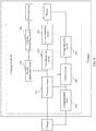
- FIG. 5 shows a specific implementation of a charging circuit.
- the charging circuit 20 is separately connected to a charger, a terminal load, and a battery.
- the charging circuit 20 includes a first adjustment circuit 210, a current detection circuit 220, a voltage detection circuit 230, and a control circuit 240.
- the first adjustment circuit 210 in the charging circuit 20 is deployed in a charging branch circuit.
- a first end of the first adjustment circuit 210 is connected to the charger; the first end of the first adjustment circuit 210 is further connected to the terminal load; a second end of the first adjustment circuit 210 is connected to a first end of the current detection circuit 220; and a third end of the first adjustment circuit 210 is connected to the control circuit 240.
- the first adjustment circuit may be a MOS transistor.
- the first end of the first adjustment circuit 210 is connected to a positive electrode of the charger.
- a second end of the current detection circuit 220 is connected to a positive electrode of the battery.
- the current detection circuit may be connected in series between a negative electrode of the battery and the charger.
- the negative electrode of the battery is connected to the charger. It may be understood that the negative electrode of the battery is connected to a negative electrode of the charger.
- a detection end of the voltage detection circuit 230 is connected in parallel at the positive and negative electrodes of the battery, and an output end of the voltage detection circuit 230 is further connected to the control circuit 240.
- the voltage detection circuit 230 is configured to: detect voltages at two ends of the battery to obtain a voltage value of the battery, and send the voltage value of the battery to the control circuit 240.
- the current detection circuit 220 is configured to: detect a current of the charging circuit to obtain a current value of the charging circuit, and send the current value to the first adjustment circuit 210.
- the control circuit 240 is configured to: determine a charging mode according to the voltage value of the battery, and determine a current upper limit value according to the charging mode.
- the first adjustment circuit 210 is configured to obtain the current value and the current upper limit value; and is further configured to: determine whether the current value is greater than the current upper limit value, and when the current value is greater than the current upper limit value, adjust upward an impedance of the first adjustment circuit according to the current value.
- the current detection circuit 210 is further connected to the control circuit 240.
- the current detection circuit 210 is further configured to send the current value to the control circuit 240.
- the control circuit 240 is configured to: determine whether the current value is greater than the current upper limit value; and when the current value is greater than the current upper limit value, send an adjustment instruction to the charger, so that the charger adjusts downward output power, an output current, or an output voltage.
- the charger adjusts downward the output current. In this case, a charging current decreases. To ensure charging efficiency, the impedance of the first adjustment circuit 210 needs to be adjusted downward. Details are as follows:
- the control circuit 240 is further configured to determine a current lower limit value according to the charging mode.
- the first adjustment circuit 210 is configured to: obtain the current lower limit value; determine whether the current value is less than the current lower limit value; and when the current value is less than the current lower limit value, adjust downward the impedance of the adjustment circuit according to the current value.
- a charging circuit 20 shown in FIG. 6 further includes a protection circuit 250.
- the protection circuit 250 may be configured to prevent an overvoltage or an overcurrent.
- the protection circuit 250 is connected in series between the charger and the first adjustment circuit 210.
- the control circuit 240 is further connected to the protection circuit 250.
- the control circuit 240 is further configured to: determine a protection trigger condition according to the charging mode, and send the protection trigger condition to the protection circuit 250.
- the protection circuit 250 is configured to: detect the output current of the charger to determine an output current value; determine whether the output current value meets the protection trigger condition; and when the output current value meets the protection trigger condition, open a switch to interrupt charging.
- the protection trigger condition includes both a current trigger protection condition and a voltage trigger protection condition.
- the protection circuit 250 is configured to: detect the output current of the charger to determine the output current value; determine whether the output current value is greater than the current protection trigger condition; and when the output current value is greater than the current protection trigger condition, open the switch to interrupt charging.
- the protection circuit 250 may detect whether a voltage of the battery is an overvoltage and detect whether the output voltage of the charger is an overvoltage. Therefore, the voltage protection trigger condition includes a battery voltage protection trigger condition and a charger voltage trigger protection condition. Specifically, the voltage of the battery corresponds to the battery voltage protection trigger condition, and the output voltage of the charger corresponds to the charger voltage protection trigger condition. It should be noted that the protection circuit 250 is further connected to the voltage detection circuit 230 to obtain the voltage value of the battery.
- the protection circuit 250 is further configured to: determine whether the voltage value of the battery is greater than the voltage protection trigger condition; and when the voltage value of the battery is greater than the voltage protection trigger condition, open the switch to interrupt charging.
- the protection circuit 250 is further configured to: detect the output voltage of the charger to obtain an output voltage value; determine whether the output voltage value is greater than the charger voltage protection trigger condition; and when the output voltage value is greater than the charger voltage protection trigger condition, open the switch to interrupt charging.
- the charging circuit 20 further includes a communication circuit 260.
- the communication circuit 260 is connected to the control circuit 240.
- the control circuit 240 needs to interact with the charger to control the charger to adjust the output power, the output voltage, or the output current.
- the control circuit 240 is further configured to send the charging mode to the communication circuit 260.
- the communication circuit 260 is configured to send the charging mode to the charger, so that the charger performs charging according to the charging mode.
- the communication circuit 260 may be connected to the charger by using a connection cable to perform information transfer. Alternatively, the communication circuit may interact with the charger in a wireless manner.
- the charging circuit 20 further includes a second adjustment circuit 270 and a current monitoring circuit 280.
- the second adjustment circuit 270 and the current monitoring circuit 280 are connected in series between the first end of the first adjustment circuit 210 and the terminal load.
- the current monitoring circuit 280 is configured to: monitor a decrease amplitude of a current of the terminal load; and when the decrease amplitude exceeds a preset threshold, send an adjustment instruction to the second adjustment circuit.
- the second adjustment circuit 270 is configured to adjust upward an impedance of the second adjustment circuit according to the adjustment instruction.
- the second adjustment circuit 270 is further configured to restore, after preset duration, the impedance of the second adjustment circuit 270 to a state before the impedance is adjusted upward.
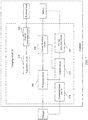
- FIG. 7 provides another specific charging circuit 30.
- the charging circuit 30 is separately connected to a charger, a terminal load, and a battery.
- the charging circuit 30 includes an adjustment circuit 310, a current monitoring circuit 320, a current detection circuit 330, a voltage detection circuit 340, a control circuit 350, a protection circuit 360, and a communication circuit 370.
- a first end of the adjustment circuit 310 is connected to the charger; a second end of the adjustment circuit 310 is connected to a first end of the current monitoring circuit 320; and a second end of the current monitoring circuit 320 is connected to the terminal load.
- a positive electrode of the charger is connected to a positive electrode of the battery; and a negative electrode of the charger is connected to a negative electrode of the battery.
- the current monitoring circuit 320 is configured to: monitor a decrease amplitude of a current of the terminal load; and when the decrease amplitude exceeds a preset threshold, send an adjustment instruction to the adjustment circuit 310.
- the adjustment circuit 320 is configured to adjust upward an impedance of the adjustment circuit according to the adjustment instruction.
- the adjustment circuit 320 is further configured to: after preset duration for which the impedance of the adjustment circuit is adjusted upward, restore the impedance of the adjustment circuit 320 to a state before the impedance is adjusted upward.
- the protection circuit 360 and the current detection circuit 330 are connected in series between the charger and the battery.
- the voltage detection circuit 340 is connected in parallel at two ends of the battery.
- the control circuit 350 is connected to the current detection circuit 330, is further connected to the voltage detection circuit 340, and is further connected to the protection circuit 360.
- the voltage detection circuit 340 is configured to: detect voltages at the two ends of the battery to obtain a voltage value of the battery, and send the voltage value of the battery to the control circuit 350.
- the current detection circuit 330 is configured to detect a current of the charging circuit to obtain a current value of the charging circuit.
- the control circuit 350 is configured to determine a charging mode according to the voltage value of the battery.
- the control circuit 350 is further configured to: when the current value is greater than a current upper limit value, send, to the charger by using the communication circuit 370, an instruction for adjusting downward an output voltage or output power.
- the control circuit 350 is further configured to: when the current value is less than a current lower limit value, send, to the charger by using the communication circuit 370, an instruction for adjusting upward the output voltage or the output power.
- the protection circuit 360 is configured to: detect an output current of the charger to determine an output current value; determine whether the output current value meets the protection trigger condition; and when the output current value meets the protection trigger condition, open a switch to interrupt charging.
- a specific charging circuit is provided, as shown in FIG. 8 .
- the charging circuit adjusts a charging current by using a feature that a drain-source on-state resistance of a MOS transistor changes with a drive voltage.
- a relationship between the drain-source on-state resistance of the MOS transistor and the drive voltage is shown in FIG. 9 .
- the MOS transistor when the drive voltage reaches a switch-on voltage, the MOS transistor is switched on, and a conductive impedance is maximum. As a vgs voltage (the drive voltage) increases, the conductive impedance gradually decreases.
- the MOS transistor may be used as a switching tube and an adjustment component to implement adjustment and protection in a charging process.
- the charging circuit shown in FIG. 8 includes a protection circuit, an adjustment circuit, a first current detection circuit, a second current detection circuit, a voltage detection circuit, a communication circuit, and a control circuit.
- the protection circuit includes resistors R1 and R2 and comparators CMP1 and CMP2.
- the R1 and the R2 form a voltage division network and detect an input voltage.
- the CMP1 compares a detected voltage with an input overvoltage threshold to determine whether the detected voltage is an input overvoltage.
- the first current detection circuit is configured to detect a current passing through the protection circuit and the adjustment circuit, and may be specifically a resistor or an amplification circuit. Alternatively, a detected current value may be obtained by dividing a voltage drop between two ends of the MOS transistor by a drain-source on-state resistance value of the MOS transistor. The detected current value is compared with an overcurrent threshold in a comparison circuit of the CMP2 to determine whether an overcurrent occurs.
- the voltage detection circuit includes resistors R3 and R4.
- the R3 and the R4 form a voltage division network, detect a voltage of a battery to obtain a voltage value of the battery, and provide the voltage of the battery for the control circuit.
- the control circuit is configured to determine a protection threshold of the protection circuit and an adjustment threshold of the adjustment circuit according to the voltage value of the battery.
- the second current detection circuit includes a resistor R5 and an amplification circuit OP1.
- the R5 and the OP1 form a charging current sampling and amplification circuit.
- the OP1 may be one of an in-phase amplification circuit, a reverse-phase amplification circuit, or a differential amplification circuit.
- the second current detection circuit is configured to detect a charging current.
- the adjustment circuit includes two MOS transistors (Q1 and Q2), a drive circuit, and a control logic circuit. It should be noted that the adjustment circuit may alternatively include one MOS transistor because a current adjustment function can also be achieved by using one MOS transistor.
- the control logic circuit compares the charging current with a specified lower limit value of a charging current adjustment threshold. If the charging current is lower than the lower limit value of the charging current adjustment threshold, the control logic circuit gradually increases the drive voltage of the MOS transistor. The conductive impedance of the MOS transistor gradually decreases until the conductive impedance of the MOS transistor reaches a lower limit value, so as to increase the charging current.
- the control logic circuit compares the charging current with a specified upper limit value of the charging current adjustment threshold. If the charging current is higher than the upper limit of the charging current adjustment threshold, the control logic circuit decreases the drive voltage of the MOS transistor. The conductive impedance of the MOS transistor gradually increases, so as to decrease the charging current.
- the drive circuit includes a DC/DC converting circuit and separately outputs a voltage to the Q1 and the Q2 according to an instruction of the control logic circuit, so as to control conductive impedances of the Q1 and the Q2.
- the Q1 and the Q2 are connected in series to the battery.
- the two MOS transistors Q1 and Q2 control closing and opening of a charging path.
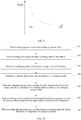
- the charging circuit shown in FIG. 8 may adjust the charging current by following the following steps:
- An embodiment of the present invention further provides a charging method.
- the method specifically includes: detecting a voltage of a battery to obtain a voltage value of the battery; selecting a charging mode according to the voltage value of the battery, where common charging modes include 8 A charging, 6 A charging, 4 A charging, and the like; determining a current upper limit value and a current lower limit value of an adjustment circuit according to the charging mode; when a charging current value exceeds the current upper limit value, adjusting upward an impedance of the adjustment circuit, so as to decrease charging power at a battery end; then requesting a control circuit to adjust downward an output voltage of a charger; and after the charger adjusts downward the output voltage, gradually adjusting a conductive impedance of the adjustment circuit to a minimum, where when the voltage value of the battery reaches a charging voltage cut-off threshold and a charging current reaches a charging current cut-off threshold, the protection circuit is open and the charging ends.
- FIG. 10 provides a charging method.
- the method includes the following steps:
- the charging current when the charging current suddenly increases, the charging current may be adjusted, so as to prevent damage to the charging circuit and the battery due to an excessively high charging current. Further, after the charger adjusts downward an output current, the charging current decreases. In this case, an impedance of an adjustment circuit in the charging circuit may be adjusted downward to increase the charging current, so as to ensure charging efficiency.
- the disclosed system, apparatus, and method may be implemented in other manners.
- the described apparatus embodiment is merely an example.
- the unit division is merely logical function division and may be other division in actual implementation.
- a plurality of units or components may be combined or integrated into another system, or some features may be ignored or not performed.
- the displayed or discussed mutual couplings or direct couplings or communication connections may be implemented through some interfaces.
- the indirect couplings or communication connections between the apparatuses or units may be implemented in electronic, mechanical, or other forms.
- the units described as separate parts may or may not be physically separate, and parts displayed as units may or may not be physical units, may be located in one position, or may be distributed on a plurality of network units. Some or all of the units may be selected according to actual requirements to achieve the objectives of the solutions of the embodiments.
- functional units in the embodiments of the present invention may be integrated into one processing unit, or each of the units may exist alone physically, or two or more units are integrated into one unit.
Landscapes
- Engineering & Computer Science (AREA)
- Power Engineering (AREA)
- Charge And Discharge Circuits For Batteries Or The Like (AREA)
- Secondary Cells (AREA)
Abstract
Description
- The present invention relates to charging technologies, and in particular, to a charging circuit, a terminal, and a charging system.
- With development of science and technology, functions of terminals become stronger, and users can perform office work and entertainment by using the terminals. Therefore, the terminals have become an indispensable part in people's daily life. However, an endurance capability of a terminal is limited, and a user needs to continuously charge the terminal. To ensure that the user can properly use the terminal, a fast technology becomes a preferred solution of charging.
- Currently, common fast charging technologies may mainly be classified into two types: a low-voltage high-current fast charging technology and a high-voltage low-current fast charging technology. For both low-voltage high-current fast charging and high-voltage low-current fast charging, a current in a charging circuit of a terminal may be converted, when being input into a battery, to a higher charging current (which cannot exceed a maximum safe charging current that the battery can bear or a safe charging current that does not damage a battery life). In this case, how to ensure charging safety of fast charging when high-current charging is performed on the battery becomes particularly important.
- As shown in
FIG. 1 , an electronic device charging control apparatus is provided in the prior art. In a process of charging a battery in an electronic device by the electronic device charging control apparatus, a power adapter first charges the battery by means of constant-voltage output. After receiving a fast charging instruction command sent by a charging control module, the power adapter adjusts an output voltage according to a battery voltage fed back by the charging control module, and adjusts, when the output voltage meets a fast charging voltage condition preset by the charging control module, an output current and the output voltage according to a fast charging current value and a fast charging voltage value, so as to perform fast charging on the battery. In addition, the charging control module introduces a direct current from the power adapter to charge the battery. In a fast charging process, the power adapter further adjusts the output current in real time according to the output voltage of the power adapter and the battery voltage, so that fast charging of the battery is implemented by adjusting the output current and the output voltage of the power adapter. - It can be learned from the foregoing that in the technical solution, the power adapter obtains, in a real-time communication manner, feedback information of a charging current and a charging voltage from the charging control module in the electronic device, and performs real-time adjustment in the power adapter. The technical solution is applicable to a scenario in which a requirement on real-time adjustment is relatively low in a charging process. In a charging scenario in which a requirement on real-time adjustment is relatively high, if a current required by a terminal load suddenly decreases and output adjustment of the power adapter is not performed in time, the charging current flowing to the battery suddenly increases. This easily causes a potential safety threat to a charging circuit and a charged battery in the electronic device.
- Embodiments of the present invention provide a charging circuit, a terminal, and a charging system, so that in a scenario in which a charging current suddenly increases during charging because a current consumed by a terminal load decreases and an output current from a power adapter cannot be adjusted in time, the charging current can be adjusted and controlled, so as to prevent damage to a battery or the charging circuit due to an excessively high charging current, thereby ensuring charging safety.
- A first aspect of the present invention provides a charging circuit. The charging circuit is separately connected to a charger, a terminal load, and a battery, so that when charging the battery by using the charging circuit, the charger can further supply power to the terminal load.
- Specifically, the charging circuit includes a first adjustment circuit, a current detection circuit, a voltage detection circuit, and a control circuit.
- A first end of the first adjustment circuit is connected to the charger; a second end of the first adjustment circuit is connected to a positive electrode of the battery; the second end of the first adjustment circuit is further connected to the terminal load; and a third end of the first adjustment circuit is connected to the control circuit.
- A negative electrode of the battery is connected to the charger.
- The current detection circuit is connected in series between the second end of the first adjustment circuit and the positive electrode of the battery, or is connected in series between the negative electrode of the battery and the charger.
- A detection end of the voltage detection circuit is connected in parallel at the positive and negative electrodes of the battery, and an output end of the voltage detection circuit is further connected to the control circuit.
- The voltage detection circuit is configured to: detect voltages at two ends of the battery to obtain a voltage value of the battery, and send the voltage value of the battery to the control circuit.
- The current detection circuit is configured to: detect a current of the charging circuit to obtain a current value of the charging circuit, and send the current value to the first adjustment circuit.
- The control circuit is configured to: determine a charging mode according to the voltage value of the battery, and determine a current upper limit value according to the charging mode.
- The first adjustment circuit is configured to obtain the current value and the current upper limit value; and is further configured to: compare the current value with the current upper limit value to determine whether the current value is greater than the current upper limit value, and when the current value is greater than the current upper limit value, adjust upward an impedance of the first adjustment circuit according to the current value.
- It should be noted that an objective of adjusting upward the impedance of the first adjustment circuit is to decrease a charging current, that is, a larger current value indicates a higher adjusted impedance of the first adjustment circuit.
- Further, it should be noted that the current detection circuit is further connected to the control circuit.
- The current detection circuit is further configured to send the current value to the control circuit.
- The control circuit is configured to: determine whether the current value is greater than the current upper limit value; and when the current value is greater than the current upper limit value, send an adjustment instruction to the charger, so that the charger adjusts downward output power, an output current, or an output voltage.
- With reference to the first aspect, it should be noted that the control circuit is further configured to determine a current lower limit value according to the charging mode. The first adjustment circuit is further configured to: obtain the current lower limit value; compare the current value with the current lower limit value to determine whether the current value is less than the current lower limit value; and when the current value is less than the current lower limit value, adjust downward the impedance of the first adjustment circuit according to the current value.
- It should be noted that if the impedance of the first adjustment circuit is currently relatively high, the output current of the charger decreases after the control circuit interacts with the charger. In this case, the charging current of the charging circuit decreases and charging efficiency is affected. To ensure the charging efficiency of the battery, in this case, the impedance of the first adjustment circuit needs to be adjusted downward to increase the charging current.
- With reference to the first aspect, to prevent an overvoltage or an overcurrent, the charging circuit further includes a protection circuit. The protection circuit is connected in series between the charger and the first end of the first adjustment circuit. The control circuit is further connected to the protection circuit. The control circuit is further configured to: determine a protection trigger condition according to the charging mode; and send the protection trigger condition to the protection circuit. The protection circuit is configured to: detect the output current of the charger to determine an output current value; determine whether the output current value meets the protection trigger condition; and when the output current value meets the protection trigger condition, open a switch to interrupt charging.
- It should be noted that the protection trigger condition includes a current protection trigger condition and a voltage protection trigger condition. That is, the protection circuit is specifically configured to: detect the output current of the charger to determine the output current value; determine whether the output current value is greater than the current protection trigger condition; and when the output current value is greater than the current protection trigger condition, open the switch to interrupt charging.
- It may be understood that the protection circuit may detect whether a voltage of the battery is an overvoltage and detect whether the output voltage of the charger is an overvoltage. Therefore, the voltage protection trigger condition includes a battery voltage protection trigger condition and a charger voltage trigger protection condition. Specifically, the voltage of the battery corresponds to the battery voltage protection trigger condition, and the output voltage of the charger corresponds to the charger voltage protection trigger condition.
- Further, the protection circuit is further connected to the voltage detection circuit to obtain the voltage value of the battery. The protection circuit is further configured to: determine whether the voltage value of the battery is greater than the battery voltage protection trigger condition; and when the voltage value of the battery is greater than the battery voltage protection trigger condition, open the switch to interrupt charging.
- Further, the protection circuit is further configured to: detect the output voltage of the charger to obtain an output voltage value; determine whether the output voltage value is greater than the charger voltage protection trigger condition; and when the output voltage value is greater than the charger voltage protection trigger condition, open the switch to interrupt charging.
- With reference to the first aspect, it should be noted that the control circuit, the charging circuit further includes a communication circuit. The communication circuit is connected to the control circuit.
- The control circuit is further configured to send the charging mode to the communication circuit.
- The communication circuit is configured to send the charging mode to the charger, so that the charger performs charging according to the charging mode.
- It should be noted that the communication circuit may be connected to the charger by using a connection cable or may interact with the charger in a wireless manner to perform information transfer.
- With reference to the first aspect, to adjust the charging current more precisely, the charging circuit further includes a second adjustment circuit.
- The second adjustment circuit is connected in series between the second end of the first adjustment circuit and the positive electrode of the battery. It should be noted that if the current detection circuit is connected in series between the first adjustment circuit and the positive electrode of the battery, alternatively, the second adjustment circuit may be connected in series between the positive electrode of the battery and the current detection circuit, or may be connected in series between the second end of the first adjustment circuit and the current detection circuit.
- The second adjustment circuit is further connected to the control circuit.
- The control circuit is further configured to determine an adjustment threshold of the second adjustment circuit according to the charging mode.
- The second adjustment circuit is configured to adjust an impedance of the second adjustment circuit according to the current value and the adjustment threshold of the second adjustment circuit.
- Specifically, it should be noted that the adjustment threshold of the second adjustment circuit also includes an upper threshold and a lower threshold. It may be understood that when the current value is greater than the upper threshold, the impedance of the second adjustment circuit is adjusted upward to decrease the charging current; or when the current value is less than the lower threshold, the impedance of the second adjustment circuit is adjusted downward to increase the charging current.
- With reference to the first aspect, it should be noted that to prevent a current required by the terminal load from suddenly decreasing, the charging circuit further includes a third adjustment circuit and a current monitoring circuit.
- The third adjustment circuit and the current monitoring circuit are connected in series between the second end of the first adjustment circuit and the terminal load.
- The current monitoring circuit is configured to: monitor a decrease amplitude of a current of the terminal load; and when the decrease amplitude exceeds a preset threshold, send an adjustment instruction to the third adjustment circuit.
- The third adjustment circuit is configured to adjust upward an impedance of the third adjustment circuit according to the adjustment instruction.
- Further, it should be noted that the third adjustment circuit is further configured to restore, after preset duration, the impedance of the third adjustment circuit to a state before the impedance is adjusted upward. Alternatively, the third adjustment circuit is further configured to adjust downward the impedance of the third adjustment circuit after preset duration.
- It should be noted that the preset duration is greater than current adjustment duration of the charger. After the current required by the terminal load decreases, the current of the charging circuit increases. Therefore, in this case, the control circuit sends, to the charger, an instruction for decreasing the output current. After receiving the instruction, the charger has the current adjustment duration, that is, the charger adjusts the current to a target value in the current adjustment duration.
- A second aspect of the present invention discloses another charging circuit. The charging circuit is separately connected to a charger, a terminal load, and a battery, and the charging circuit includes a first adjustment circuit, a current detection circuit, a voltage detection circuit, and a control circuit.
- Different from the charging circuit disclosed in the first aspect, the adjustment circuit in the charging circuit is deployed in a branch circuit.
- Specifically, a first end of the first adjustment circuit is connected to the charger; the first end of the first adjustment circuit is further connected to the terminal load; a second end of the first adjustment circuit is connected to a positive electrode of the battery; and a third end of the first adjustment circuit is connected to the control circuit.
- A negative electrode of the battery is connected to the charger.
- The current detection circuit is connected in series between the second end of the first adjustment circuit and the positive electrode of the battery, or is connected in series between the negative electrode of the battery and the charger.
- A detection end of the voltage detection circuit is connected in parallel at the positive and negative electrodes of the battery, and an output end of the voltage detection circuit is connected to the control circuit.
- The voltage detection circuit is configured to: detect voltages at two ends of the battery to obtain a voltage value of the battery, and send the voltage value of the battery to the control circuit.
- The current detection circuit is configured to: detect a current of the charging circuit to obtain a current value of the charging circuit, and send the current value to the first adjustment circuit.
- The control circuit is configured to: determine a charging mode according to the voltage value of the battery, and determine a current upper limit value according to the charging mode.
- The first adjustment circuit is configured to obtain the current value and the current upper limit value; and is further configured to: compare the current value with the current upper limit value to determine whether the current value is greater than the current upper limit value, and when the current value is greater than the current upper limit value, adjust upward an impedance of the first adjustment circuit according to the current value.
- Further, it should be noted that the current detection circuit is further connected to the control circuit.
- The current detection circuit is further configured to send the current value to the control circuit.
- The control circuit is configured to: determine whether the current value is greater than the current upper limit value; and when the current value is greater than the current upper limit value, send an adjustment instruction to the charger, so that the charger adjusts downward output power, an output current, or an output voltage.
- With reference to the second aspect, it should be noted that after the control circuit interacts with the charger, the charger adjusts downward the output current. In this case, a charging current decreases. To ensure charging efficiency, the impedance of the first adjustment circuit needs to be adjusted downward. Details are as follows:
- The control circuit is further configured to determine a current lower limit value according to the charging mode.
- The first adjustment circuit is configured to: obtain the current lower limit value; compare the current value with the current lower limit value to determine whether the current value is less than the current lower limit value; and when the current value is less than the current lower limit value, adjust downward the impedance of the adjustment circuit according to the current value.
- With reference to the second aspect, to prevent an overvoltage or an overcurrent, the charging circuit further includes a protection circuit.
- The protection circuit is connected in series between the charger and the first end of the first adjustment circuit.
- The control circuit is further connected to the protection circuit.
- The control circuit is further configured to: determine a protection trigger condition according to the charging mode; and send the protection trigger condition to the protection circuit.
- The protection circuit is configured to: detect the output current of the charger to determine an output current value; determine whether the output current value meets the protection trigger condition; and when the output current value meets the protection trigger condition, open a switch to interrupt charging.
- It may be understood that the protection trigger condition includes both a current trigger protection condition and a voltage trigger protection condition.
- Specifically, the protection circuit is configured to: determine whether the output current value is greater than the current protection trigger condition; and when the output current value is greater than the current protection trigger condition, open the switch to interrupt charging.
- It may be understood that the protection circuit may detect whether a voltage of the battery is an overvoltage and detect whether an output voltage of the charger is an overvoltage. Therefore, the voltage protection trigger condition includes a battery voltage protection trigger condition and a charger voltage trigger protection condition. Specifically, the voltage of the battery corresponds to the battery voltage protection trigger condition, and the output voltage of the charger corresponds to the charger voltage protection trigger condition.
- Further, the protection circuit is further connected to the voltage detection circuit to obtain the voltage value of the battery. The protection circuit is further configured to: determine whether the voltage value of the battery is greater than the battery voltage protection trigger condition; and when the voltage value of the battery is greater than the battery voltage protection trigger condition, open the switch to interrupt charging.
- Further, the protection circuit is further configured to: detect the output voltage of the charger to obtain an output voltage value; determine whether the output voltage value is greater than the charger voltage protection trigger condition; and when the output voltage value is greater than the charger voltage protection trigger condition, open the switch to interrupt charging.
- With reference to the second aspect, it should be noted that the control circuit needs to interact with the charger to control the charger to adjust the output power, the output voltage, or the output current. Therefore, the charging circuit further includes a communication circuit. The communication circuit is connected to the control circuit.
- The control circuit is further configured to send the charging mode to the communication circuit.
- The communication circuit is configured to send the charging mode to the charger, so that the charger performs charging according to the charging mode.
- It should be noted that the communication circuit may be connected to the charger by using a connection cable to perform information transfer. Alternatively, the communication circuit may interact with the charger in a wireless manner.
- With reference to the second aspect, optionally, the charging circuit further includes a second adjustment circuit and a current monitoring circuit.
- The second adjustment circuit and the current monitoring circuit are connected in series between the first end of the first adjustment circuit and the terminal load.
- The current monitoring circuit is configured to: monitor a decrease amplitude of a current of the terminal load; and when the decrease amplitude exceeds a preset threshold, send an adjustment instruction to the second adjustment circuit.
- The second adjustment circuit is configured to adjust upward an impedance of the second adjustment circuit according to the adjustment instruction.
- Further, it should be noted that the second adjustment circuit is further configured to restore, after preset duration, the impedance of the second adjustment circuit to a state before the impedance is adjusted upward.
- A third aspect of the present invention discloses another charging circuit. The charging circuit is separately connected to a charger, a terminal load, and a battery, and the charging circuit includes an adjustment circuit and a current monitoring circuit.
- A first end of the adjustment circuit is connected to the charger; a second end of the adjustment circuit is connected to a first end of the current monitoring circuit; and a second end of the current monitoring circuit is connected to the terminal load.
- A positive electrode of the charger is connected to a positive electrode of the battery; and a negative electrode of the charger is connected to a negative electrode of the battery.
- The current monitoring circuit is configured to: monitor a decrease amplitude of a current of the terminal load; and when the decrease amplitude exceeds a preset threshold, send an adjustment instruction to the adjustment circuit.
- The adjustment circuit is configured to adjust upward an impedance of the adjustment circuit according to the adjustment instruction.
- Further, it should be noted that the adjustment circuit is further configured to: after preset duration for which the impedance of the adjustment circuit is adjusted upward, restore the impedance of the adjustment circuit to a state before the impedance is adjusted upward.
- With reference to the third aspect, it should be noted that to prevent an overvoltage or an overcurrent, the charging circuit further includes a current detection circuit, a voltage detection circuit, a control circuit, and a protection circuit.
- The protection circuit is connected in series between the charger and the positive electrode of the battery.
- The current detection circuit is connected in series between the protection circuit and the positive electrode of the battery, or is connected in series between the negative electrode of the battery and the charger.
- A detection end of the voltage detection circuit is connected in parallel at the positive and negative electrodes of the battery.
- The control circuit is connected to the current detection circuit, is further connected to an output end of the voltage detection circuit, and is further connected to the protection circuit.
- The voltage detection circuit is configured to: detect voltages at two ends of the battery to obtain a voltage value of the battery, and send the voltage value of the battery to the control circuit.
- The current detection circuit is configured to: detect a current of the charging circuit to obtain a current value of the charging circuit, and send the current value to the protection circuit.
- The control circuit is configured to: determine a charging mode according to the voltage value of the battery, and determine a protection trigger condition according to the charging mode.
- The protection circuit is configured to: detect an output current of the charger to determine an output current value; determine whether the output current value meets the protection trigger condition; and when the output current value meets the protection trigger condition, open a switch to interrupt charging.
- It may be understood that the protection circuit may detect whether a voltage of the battery is an overvoltage and detect whether an output voltage of the charger is an overvoltage. Therefore, the voltage protection trigger condition includes a battery voltage protection trigger condition and a charger voltage trigger protection condition. Specifically, the voltage of the battery corresponds to the battery voltage protection trigger condition, and the output voltage of the charger corresponds to the charger voltage protection trigger condition.
- Further, the protection circuit is further connected to the voltage detection circuit to obtain the voltage value of the battery. The protection circuit is further configured to: determine whether the voltage value of the battery is greater than the battery voltage protection trigger condition; and when the voltage value of the battery is greater than the battery voltage protection trigger condition, open the switch to interrupt charging.
- Further, the protection circuit is further configured to: detect an output voltage of the charger to obtain an output voltage value; determine whether the output voltage value is greater than the charger voltage protection trigger condition; and when the output voltage value is greater than the charger voltage protection trigger condition, open the switch to interrupt charging.
- A fourth aspect of the present invention further discloses a terminal. The terminal includes the charging circuit according to any one of the first aspect to the third aspect.
- A fifth aspect of the present invention discloses a charging system. The charging system includes a charger, a connection cable, and the terminal according to the fourth aspect.
- The charger is connected to the terminal by using the connection cable.
- A sixth aspect of the present invention discloses a charging method. The method includes:
detecting a charging current to obtain a charging current value; detecting a voltage of a battery to obtain a voltage value of the battery; determining a charging mode matching the voltage value of the battery; determining a current upper limit value according to the charging mode; and when the charging current value is greater than the current upper limit value, adjusting upward an impedance of a charging path according to the charging current value. - Further, it should be noted that the method further includes: determining a current lower limit value according to the charging mode; and when the charging current value is less than the current lower limit value, adjusting downward the impedance of the charging path according to the charging current value.
- It can be learned from the foregoing that technical solutions of the present invention provide a charging circuit, a terminal, and a charging system. The charging circuit is separately connected to the charger, the terminal load, and the battery. The charging circuit includes the first adjustment circuit, the current detection circuit, the voltage detection circuit, and the control circuit. The first end of the first adjustment circuit is connected to the charger; the second end of the first adjustment circuit is connected to the positive electrode of the battery; the second end of the first adjustment circuit is further connected to the terminal load; and the third end of the first adjustment circuit is connected to the control circuit. The negative electrode of the battery is connected to the charger. The current detection circuit is connected in series between the second end of the first adjustment circuit and the positive electrode of the battery, or is connected in series between the negative electrode of the battery and the charger. The detection end of the voltage detection circuit is connected in parallel at the positive and negative electrodes of the battery. The output end of the voltage detection circuit is connected to the control circuit. The voltage detection circuit is configured to: detect voltages at two ends of the battery to obtain a voltage value of the battery, and send the voltage value of the battery to the control circuit. The current detection circuit is configured to: detect a current of the charging circuit to obtain a current value of the charging circuit, and send the current value to the first adjustment circuit. The control circuit is configured to: determine a charging mode according to the voltage value of the battery, and determine a current upper limit value according to the charging mode. The first adjustment circuit is configured to obtain the current value and the current upper limit value; and is further configured to: compare the current value with the current upper limit value to determine whether the current value is greater than the current upper limit value, and when the current value is greater than the current upper limit value, adjust upward an impedance of the first adjustment circuit according to the current value. The charging circuit provided in the present invention can adjust, when a charging current suddenly increases, the charging current, so as to prevent damage to the charging circuit and the battery due to an excessively high charging current. Further, after the charger adjusts downward an output current, the charging current decreases. In this case, the impedance of the adjustment circuit in the charging circuit may be adjusted downward to increase the charging current, so as to ensure charging efficiency.
- To describe the technical solutions in the embodiments of the present invention more clearly, the following briefly describes the accompanying drawings required for describing the embodiments of the present invention. Apparently, the accompanying drawings in the following description show merely some embodiments of the present invention, and a person of ordinary skill in the art may still derive other drawings from these accompanying drawings without creative efforts.
-
FIG. 1 is an electronic device charging control apparatus in the prior art; -
FIG. 2 is a schematic diagram of a charging system according to an embodiment of the present invention; -
FIG. 3 is a schematic diagram of a charging circuit according to an embodiment of the present invention; -
FIG. 4 is a schematic diagram of a charging circuit according to another embodiment of the present invention; -
FIG. 5 is a schematic diagram of a charging circuit according to another embodiment of the present invention; -
FIG. 6 is a schematic diagram of a charging circuit according to another embodiment of the present invention; -
FIG. 7 is a schematic diagram of a charging circuit according to another embodiment of the present invention; -
FIG. 8 is a schematic diagram of a charging circuit according to another embodiment of the present invention; -
FIG. 9 is a line graph of a relationship between a conductive impedance of a MOS transistor and a drive voltage according to another embodiment of the present invention; and -
FIG. 10 shows a charging method according to another embodiment of the present invention. - To make the purpose, technical solutions, and advantages of the embodiments of the present invention clearer, the following describes the technical solutions of the embodiments of the present invention with reference to the accompanying drawings in the embodiments of the present invention.
- With development of science and technology, functions of terminals (for example, electronic devices such as a smartphone, a wearable device, and a tablet computer) are becoming stronger, and users can perform office work and entertainment by using the terminals, so that the terminals have become an indispensable part in people's daily life. However, an endurance capability of a terminal is limited, and a user needs to continuously charge the terminal.
- To ensure that the user can properly use the terminal, a fast technology becomes a preferred solution of charging.
- Currently, common fast charging technologies may mainly be classified into two types: a low-voltage high-current fast charging technology and a high-voltage low-current fast charging technology. For both low-voltage high-current fast charging and high-voltage low-current fast charging, a current in a charging circuit of a terminal may be converted, when being input into a battery, to a higher charging current (which cannot exceed a maximum safe charging current that the battery can bear or a safe charging current that does not damage a battery life). In this case, how to ensure charging safety of fast charging when high-current charging is performed on the battery becomes particularly important.
- As shown in
FIG. 1 , an electronic device charging control apparatus is provided in the prior art. In a process of charging a battery in an electronic device by the electronic device charging control apparatus, a power adapter first charges the battery by means of constant-voltage output. After receiving a fast charging instruction command sent by a charging control module, the power adapter adjusts an output voltage according to a battery voltage fed back by the charging control module, and adjusts, when the output voltage meets a fast charging voltage condition preset by the charging control module, an output current and the output voltage according to a fast charging current value and a fast charging voltage value, so as to perform fast charging on the battery. In addition, the charging control module introduces a direct current from the power adapter to charge the battery. In a fast charging process, the power adapter further adjusts the output current in real time according to the output voltage of the power adapter and the battery voltage, so that fast charging of the battery is implemented by adjusting the output current and the output voltage of the power adapter. - It can be learned from the foregoing that in the technical solution, the power adapter obtains, in a real-time communication manner, feedback information of a charging current and a charging voltage from the charging control module in the electronic device, and performs real-time adjustment in the power adapter. The technical solution is applicable to a scenario in which a requirement on real-time adjustment is relatively low in a charging process. In a charging scenario in which a requirement on real-time adjustment is relatively high, if a current required by a terminal load suddenly decreases and output adjustment of the power adapter is not performed in time, the charging current flowing to the battery suddenly increases. This easily causes a potential safety threat to a charging circuit and a charged battery in the electronic device.
- As shown in
FIG. 2, FIG. 1 is a charging system according to an embodiment of the present invention. By means of the charging system provided in the present invention, when a charging current suddenly increases, the charging current can be adjusted, so as to prevent damage to a charging circuit and a battery due to an excessively high charging current. - Specifically, the charging system includes a terminal, a charger, and a connection cable. The terminal is connected to the charger by using the connection cable.
- The terminal may be an electronic device such as a smartphone, a tablet computer, an intelligent wearable device, or a computer.
- As shown in
FIG. 2 , the terminal includes a terminal load, the battery, and the charging circuit of the terminal. - The charging circuit is separately connected to the charger, the terminal load, and the battery.
- It should be noted that the charging circuit is configured to: detect voltages at two ends of the battery to obtain a voltage value of the battery, determine a charging mode according to the voltage value of the battery, and determine a current upper limit value according to the charging mode; and is further configured to: detect a current of the charging circuit to obtain a current value of the charging circuit, determine whether the current value is greater than the current upper limit value, and when the current value is greater than the current upper limit value, adjust upward an impedance of the adjustment circuit according to the current value.
- Further, the charging circuit is further configured to: determine a current lower limit value according to the charging mode; determine whether the current value is less than the current lower limit value; and when the current value is less than the current lower limit value, adjust downward the impedance of the adjustment circuit according to the current value.
- It can be learned from the foregoing that by means of the charging circuit provided in the present invention, in a scenario in which a charging current suddenly increases during charging because a current consumed by a terminal load decreases and an output current from a power adapter cannot be adjusted in time, an impedance of the charging circuit can be adjusted in a charging process to decrease the charging current, so as to prevent damage to the battery or the charging circuit due to an excessively high charging current, and further ensure charging safety. Further, after the charger adjusts downward the output current, the charging current decreases. In this case, the impedance of the adjustment circuit in the charging circuit may be adjusted downward to increase the charging current, so as to ensure charging efficiency.
- As shown in
FIG. 3, FIG. 3 shows a specific implementation of a charging circuit. The chargingcircuit 10 is separately connected to a charger, a terminal load, and a battery, so that when charging the battery by using the charging circuit, the charger can further supply power to the terminal load. - Specifically, the charging
circuit 10 includes afirst adjustment circuit 110, acurrent detection circuit 120, avoltage detection circuit 130, and acontrol circuit 140. - As shown in
FIG. 3 , thefirst adjustment circuit 110 is connected to a positive electrode of the charger; a second end of thefirst adjustment circuit 110 is connected to a first end of thecurrent detection circuit 120; the second end of thefirst adjustment circuit 110 is further connected to the terminal load; and a third end of thefirst adjustment circuit 110 is connected to thecontrol circuit 140. - It should be noted that the first adjustment circuit may be a MOS transistor (that is, a metal oxide semiconductor field effect transistor which may be also referred to as a metal insulator transistor). It may be understood that the MOS transistor has three ports. The three ports are respectively a G electrode, an S electrode, and a D electrode.
- The first end may be the S electrode, the second end may be the D electrode, and the third end may be the G electrode.
- Alternatively, the first end may be the D electrode, the second end may be the P electrode, and the third end may be the G electrode. Specifically, the first adjustment circuit may adjust an impedance of the first adjustment circuit by adjusting drive voltages at G and S ends.
- A second end of the
current detection circuit 120 is connected to a positive electrode of the battery; and a negative electrode of the battery is connected to the charger. Alternatively, thecurrent detection circuit 120 is connected in series between the negative electrode of the battery and the charger; and a detection end of thevoltage detection circuit 130 is connected in parallel at the positive and negative electrodes of the battery. - It may be understood that one end of the
voltage detection circuit 130 is connected to the positive electrode of the battery, and another end is connected to the negative electrode of the battery. An output end of thevoltage detection circuit 130 is further connected to thecontrol circuit 140. It may be understood according to the connection manner that thevoltage detection circuit 130 is configured to: detect voltages at two ends of the battery to obtain a voltage value of the battery, and send the voltage value of the battery to thecontrol circuit 140. - The
current detection circuit 120 is configured to: detect a current of the charging circuit to obtain a current value of the charging circuit, and send the current value to thefirst adjustment circuit 110. - The
control circuit 140 is configured to: determine a charging mode according to the voltage value of the battery, and determine a current upper limit value according to the charging mode. - For example, the
control circuit 140 searches the following table according to the voltage value of the battery to determine the charging mode.Charging mode Battery voltage value Not charged ≤2.8 V 8 A fast charging 2.8-4.2 V 6 A fast charging 4.2-4.3 V 4 A fast charging 4.3-4.4 V Charging completed Battery voltage: 4.4 V; charging current: less than 0.03 A - Further, the
control circuit 140 searches the following table according to the charging mode to determine the current upper limit value.Charging mode Current upper limit value and current lower limit value Adjustment manner 8 A fast charging Greater than 8.3 A or less than 7.7 A Constant-current control 6 A fast charging Greater than 6.3 A or less than 5.7 A Constant-current control 4 A fast charging Greater than 4.3 A or less than 3.7 A Constant-current control 4.4 V constant-voltage charging A battery voltage reaches 4.4 V Not adjusted - The
first adjustment circuit 110 is configured to obtain the current value and the current upper limit value; and is further configured to: determine whether the current value is greater than the current upper limit value, and when the current value is greater than the current upper limit value, adjust upward an impedance of the first adjustment circuit according to the current value. - It should be noted that an objective of adjusting upward the impedance of the
first adjustment circuit 110 is to decrease a charging current, that is, a larger current value indicates a higher adjusted impedance of the first adjustment circuit. However, the impedance of the first adjustment circuit usually has a default maximum value or a manually specified maximum value. When the impedance of the adjustment circuit is adjusted to the maximum value and the charging current is still greater than the current upper limit value, the first adjustment circuit is disconnected and sends an alarm to thecontrol circuit 140, so that the control circuit re-configures a related charging parameter (for example, an output voltage of the charger or an output current of the charger) for attempt of re-charging. - Further, it should be noted that when the charging current is greater than the current upper limit value, interaction needs to be performed with the charger, so that the charger adjusts downward the output current, or output power, or the output voltage.
- Specifically, the
current detection circuit 120 is further connected to thecontrol circuit 140. - The
current detection circuit 120 is further configured to send the current value to thecontrol circuit 140. - The
control circuit 140 is configured to: determine whether the current value is greater than the current upper limit value; and when the current value is greater than the current upper limit value, send an adjustment instruction to the charger, so that the charger adjusts downward output power, an output current, or an output voltage. - Further, it should be noted that when the charger adjusts downward the output current, the output voltage, or the output power, the current of the charging circuit decreases. If a current value of a decreased current is less than a current lower limit value, to ensure charging efficiency, the impedance of the
first adjustment circuit 110 needs to be adjusted downward, so as to increase the charging current. - Specifically, the
control circuit 140 is further configured to determine a current lower limit value according to the charging mode. Thefirst adjustment circuit 110 is further configured to: obtain the current lower limit value; determine whether the current value is less than the current lower limit value; and when the current value is less than the current lower limit value, adjust downward the impedance of the first adjustment circuit according to the current value. - It should be noted that if the impedance of the first adjustment circuit is currently relatively high, the output current of the charger decreases after the control circuit interacts with the charger. In this case, the charging current of the charging circuit decreases and the charging efficiency is affected. To ensure the charging efficiency of the battery, the impedance of the first adjustment circuit needs to be adjusted downward to increase the charging current.
- Based on the charging circuit shown in
FIG. 3 , to prevent an overvoltage or an overcurrent, the chargingcircuit 10 further includes aprotection circuit 150. - As shown in
FIG. 4 , theprotection circuit 150 is connected in series between the charger and the first end of thefirst adjustment circuit 110. Thecontrol circuit 140 is further connected to theprotection circuit 150. - The
control circuit 140 is further configured to: determine a protection trigger condition according to the charging mode, and send the protection trigger condition to theprotection circuit 150. - For example, the
control circuit 140 may search the following table according to the charging mode to determine the protection trigger condition.Charging mode Overcurrent protection threshold Battery overvoltage protection threshold Charging cut-off 8 A fast charging 10.5 A 4.41 V 4.4 V 6 A fast charging 8.5 A 4 A fast charging 6.5 A 4.4 V constant-voltage charging 4.5 A - The
protection circuit 150 is configured to: detect an output current of the charger to determine an output current value; determine whether the output current value meets the protection trigger condition; and when the output current value meets the protection trigger condition, open a switch to interrupt charging. - It can be learned from the foregoing table that the protection trigger condition includes a current protection trigger condition and a voltage protection trigger condition. That is, the
protection circuit 150 is specifically configured to: determine whether the output current value is greater than the current protection trigger condition (an overcurrent protection threshold); and when the output current value is greater than the current protection trigger condition, open the switch to interrupt charging. - It may be understood that the
protection circuit 150 may detect whether a voltage of the battery is an overvoltage and detect whether the output voltage of the charger is an overvoltage. Therefore, the voltage protection trigger condition includes a battery voltage protection trigger condition and a charger voltage trigger protection condition. Specifically, the voltage of the battery corresponds to the battery voltage protection trigger condition, and the output voltage of the charger corresponds to the charger voltage protection trigger condition. - Further, the
protection circuit 150 is further connected to thevoltage detection circuit 130 to obtain the voltage value of the battery. - The
protection circuit 150 is further configured to: detect an output voltage of the charger to determine an output voltage value; determine whether the output voltage value is greater than the battery voltage protection trigger condition (an overvoltage protection threshold); and when the voltage value of the battery is greater than the battery voltage protection trigger condition, open the switch to interrupt charging. - Further, the protection circuit is further configured to: detect the output voltage of the charger to obtain the output voltage value; determine whether the output voltage value is greater than the charger voltage protection trigger condition; and when the output voltage value is greater than the charger voltage protection trigger condition, open the switch to interrupt charging.
- As shown in
FIG. 4 , the chargingcircuit 10 further includes acommunication circuit 160. - The
communication circuit 160 is connected to thecontrol circuit 140. - The
control circuit 140 is further configured to send the charging mode to thecommunication circuit 160. - The
communication circuit 160 is configured to send the charging mode to the charger, so that the charger performs charging according to the charging mode. - It should be noted that the communication circuit may be connected to the charger by using a connection cable or may interact with the charger in a wireless manner to perform information transfer.
- As shown in
FIG. 4 , to adjust the charging current more precisely, the charging circuit further includes asecond adjustment circuit 170. The second adjustment circuit may be a MOS transistor, or may be a slide rheostat. - The
second adjustment circuit 170 is connected in series between the second end of thefirst adjustment circuit 110 and thecurrent detection circuit 120. Alternatively, thesecond adjustment circuit 170 may be connected in series between the positive electrode of the battery and thecurrent detection circuit 120. - The
second adjustment circuit 170 is further connected to thecontrol circuit 140. - The
control circuit 140 is further configured to determine an adjustment threshold of thesecond adjustment circuit 140 according to the charging mode. - The
second adjustment circuit 140 is configured to adjust an impedance of the second adjustment circuit according to the current value and the adjustment threshold of the second adjustment circuit. - Specifically, it should be noted that the adjustment threshold of the
second adjustment circuit 140 also includes an upper threshold and a lower threshold. It may be understood that when the current value is greater than the upper threshold, the impedance of thesecond adjustment circuit 170 is adjusted upward to decrease the charging current; or when the current value is less than the lower threshold, the impedance of the second adjustment circuit is adjusted downward to increase the charging current. - As shown in
FIG. 4 , to prevent a current required by the terminal load from suddenly decreasing, the chargingcircuit 10 further includes athird adjustment circuit 180 and acurrent monitoring circuit 190. - The
third adjustment circuit 180 and thecurrent monitoring circuit 190 are connected in series between thefirst adjustment circuit 110 and the terminal load. - The
current monitoring circuit 190 is configured to: monitor a decrease amplitude of a current of the terminal load; and when the decrease amplitude exceeds a preset threshold, send an adjustment instruction to thethird adjustment circuit 180. - The
third adjustment circuit 180 is configured to adjust upward an impedance of the third adjustment circuit according to the adjustment instruction. - Further, it should be noted that because power consumed by the terminal load decreases, the
third adjustment circuit 180 needs to perform current shunting to prevent the charging current of the charging circuit from being excessively high. When monitoring that the power consumed by the terminal load decreases, a terminal instructs the charger to decrease output power or the output current. After receiving an instruction from the terminal, the charger decreases the output power or the output current. This adjustment function takes time. After the adjustment is completed, a load current of the terminal decreases. In this case, a third adjustment unit decreases the impedance or restores the impedance to a state before the impedance is adjusted upward. - Specifically, the
third adjustment circuit 180 is further configured to restore, after preset duration, the impedance of thethird adjustment circuit 180 to a state before the impedance is adjusted upward. - It should be noted that the preset duration is greater than current adjustment duration of the charger.
- After the current required by the terminal load decreases, a current of the charging circuit increases. In this case, the control circuit sends, to the charger, an instruction for decreasing the output current. After receiving the instruction, the charger has the current adjustment duration, that is, the charger adjusts the current to a target value in the current adjustment duration.
- In conclusion, referring to
FIG. 3 andFIG. 4 , it may be learned that to prevent the power consumed by the terminal load or the current from suddenly decreasing and prevent an excessively high charging current due to that the charger cannot decrease the output power or the current in time, the present invention provides a charging circuit. The charging circuit includes the adjustment circuit that can perform current shunting in time, so as to prevent damage to the charging circuit or the battery due to an excessively high charging current. Further, after the charger adjusts downward the output current, the charging current decreases. In this case, the impedance of the adjustment circuit in the charging circuit may be adjusted downward to increase the charging current, so as to ensure charging efficiency. - As shown in
FIG. 5, FIG. 5 shows a specific implementation of a charging circuit. The chargingcircuit 20 is separately connected to a charger, a terminal load, and a battery. The chargingcircuit 20 includes afirst adjustment circuit 210, acurrent detection circuit 220, avoltage detection circuit 230, and acontrol circuit 240. - Different from the charging circuit shown in
FIG. 3 , thefirst adjustment circuit 210 in the chargingcircuit 20 is deployed in a charging branch circuit. - Specifically, a first end of the
first adjustment circuit 210 is connected to the charger; the first end of thefirst adjustment circuit 210 is further connected to the terminal load; a second end of thefirst adjustment circuit 210 is connected to a first end of thecurrent detection circuit 220; and a third end of thefirst adjustment circuit 210 is connected to thecontrol circuit 240. - The first adjustment circuit may be a MOS transistor.
- It may be understood that the first end of the
first adjustment circuit 210 is connected to a positive electrode of the charger. - A second end of the
current detection circuit 220 is connected to a positive electrode of the battery. Alternatively, the current detection circuit may be connected in series between a negative electrode of the battery and the charger. - The negative electrode of the battery is connected to the charger. It may be understood that the negative electrode of the battery is connected to a negative electrode of the charger.
- A detection end of the
voltage detection circuit 230 is connected in parallel at the positive and negative electrodes of the battery, and an output end of thevoltage detection circuit 230 is further connected to thecontrol circuit 240. - The
voltage detection circuit 230 is configured to: detect voltages at two ends of the battery to obtain a voltage value of the battery, and send the voltage value of the battery to thecontrol circuit 240. - The
current detection circuit 220 is configured to: detect a current of the charging circuit to obtain a current value of the charging circuit, and send the current value to thefirst adjustment circuit 210. - The
control circuit 240 is configured to: determine a charging mode according to the voltage value of the battery, and determine a current upper limit value according to the charging mode. - The
first adjustment circuit 210 is configured to obtain the current value and the current upper limit value; and is further configured to: determine whether the current value is greater than the current upper limit value, and when the current value is greater than the current upper limit value, adjust upward an impedance of the first adjustment circuit according to the current value. - Further, it should be noted that the
current detection circuit 210 is further connected to thecontrol circuit 240. - The
current detection circuit 210 is further configured to send the current value to thecontrol circuit 240. - The
control circuit 240 is configured to: determine whether the current value is greater than the current upper limit value; and when the current value is greater than the current upper limit value, send an adjustment instruction to the charger, so that the charger adjusts downward output power, an output current, or an output voltage. - Further, it should be noted that after the
control circuit 240 interacts with the charger, the charger adjusts downward the output current. In this case, a charging current decreases. To ensure charging efficiency, the impedance of thefirst adjustment circuit 210 needs to be adjusted downward. Details are as follows: - The
control circuit 240 is further configured to determine a current lower limit value according to the charging mode. - The
first adjustment circuit 210 is configured to: obtain the current lower limit value; determine whether the current value is less than the current lower limit value; and when the current value is less than the current lower limit value, adjust downward the impedance of the adjustment circuit according to the current value. - Based on
FIG. 5 , a chargingcircuit 20 shown inFIG. 6 further includes aprotection circuit 250. Theprotection circuit 250 may be configured to prevent an overvoltage or an overcurrent. - Specifically, the
protection circuit 250 is connected in series between the charger and thefirst adjustment circuit 210. - The
control circuit 240 is further connected to theprotection circuit 250. - The
control circuit 240 is further configured to: determine a protection trigger condition according to the charging mode, and send the protection trigger condition to theprotection circuit 250. - The
protection circuit 250 is configured to: detect the output current of the charger to determine an output current value; determine whether the output current value meets the protection trigger condition; and when the output current value meets the protection trigger condition, open a switch to interrupt charging. - It may be understood that the protection trigger condition includes both a current trigger protection condition and a voltage trigger protection condition.
- Specifically, the
protection circuit 250 is configured to: detect the output current of the charger to determine the output current value; determine whether the output current value is greater than the current protection trigger condition; and when the output current value is greater than the current protection trigger condition, open the switch to interrupt charging. - It may be understood that the
protection circuit 250 may detect whether a voltage of the battery is an overvoltage and detect whether the output voltage of the charger is an overvoltage. Therefore, the voltage protection trigger condition includes a battery voltage protection trigger condition and a charger voltage trigger protection condition. Specifically, the voltage of the battery corresponds to the battery voltage protection trigger condition, and the output voltage of the charger corresponds to the charger voltage protection trigger condition. It should be noted that theprotection circuit 250 is further connected to thevoltage detection circuit 230 to obtain the voltage value of the battery. - The
protection circuit 250 is further configured to: determine whether the voltage value of the battery is greater than the voltage protection trigger condition; and when the voltage value of the battery is greater than the voltage protection trigger condition, open the switch to interrupt charging. - Further, the
protection circuit 250 is further configured to: detect the output voltage of the charger to obtain an output voltage value; determine whether the output voltage value is greater than the charger voltage protection trigger condition; and when the output voltage value is greater than the charger voltage protection trigger condition, open the switch to interrupt charging. - As shown in
FIG. 6 , the chargingcircuit 20 further includes acommunication circuit 260. Specifically, thecommunication circuit 260 is connected to thecontrol circuit 240. Thecontrol circuit 240 needs to interact with the charger to control the charger to adjust the output power, the output voltage, or the output current. - Details are as follows:
Thecontrol circuit 240 is further configured to send the charging mode to thecommunication circuit 260. - The
communication circuit 260 is configured to send the charging mode to the charger, so that the charger performs charging according to the charging mode. - It should be noted that the
communication circuit 260 may be connected to the charger by using a connection cable to perform information transfer. Alternatively, the communication circuit may interact with the charger in a wireless manner. - As shown in
FIG. 6 , the chargingcircuit 20 further includes asecond adjustment circuit 270 and acurrent monitoring circuit 280. - The
second adjustment circuit 270 and thecurrent monitoring circuit 280 are connected in series between the first end of thefirst adjustment circuit 210 and the terminal load. - The
current monitoring circuit 280 is configured to: monitor a decrease amplitude of a current of the terminal load; and when the decrease amplitude exceeds a preset threshold, send an adjustment instruction to the second adjustment circuit. - The
second adjustment circuit 270 is configured to adjust upward an impedance of the second adjustment circuit according to the adjustment instruction. - Further, it should be noted that the
second adjustment circuit 270 is further configured to restore, after preset duration, the impedance of thesecond adjustment circuit 270 to a state before the impedance is adjusted upward. - As shown in
FIG. 7, FIG. 7 provides anotherspecific charging circuit 30. The chargingcircuit 30 is separately connected to a charger, a terminal load, and a battery. The chargingcircuit 30 includes anadjustment circuit 310, acurrent monitoring circuit 320, acurrent detection circuit 330, avoltage detection circuit 340, acontrol circuit 350, aprotection circuit 360, and acommunication circuit 370. - A first end of the
adjustment circuit 310 is connected to the charger; a second end of theadjustment circuit 310 is connected to a first end of thecurrent monitoring circuit 320; and a second end of thecurrent monitoring circuit 320 is connected to the terminal load. - A positive electrode of the charger is connected to a positive electrode of the battery; and a negative electrode of the charger is connected to a negative electrode of the battery.
- The
current monitoring circuit 320 is configured to: monitor a decrease amplitude of a current of the terminal load; and when the decrease amplitude exceeds a preset threshold, send an adjustment instruction to theadjustment circuit 310. - The
adjustment circuit 320 is configured to adjust upward an impedance of the adjustment circuit according to the adjustment instruction. - Further, it should be noted that the
adjustment circuit 320 is further configured to: after preset duration for which the impedance of the adjustment circuit is adjusted upward, restore the impedance of theadjustment circuit 320 to a state before the impedance is adjusted upward. - The
protection circuit 360 and thecurrent detection circuit 330 are connected in series between the charger and the battery. - The
voltage detection circuit 340 is connected in parallel at two ends of the battery. - The
control circuit 350 is connected to thecurrent detection circuit 330, is further connected to thevoltage detection circuit 340, and is further connected to theprotection circuit 360. - The
voltage detection circuit 340 is configured to: detect voltages at the two ends of the battery to obtain a voltage value of the battery, and send the voltage value of the battery to thecontrol circuit 350. - The
current detection circuit 330 is configured to detect a current of the charging circuit to obtain a current value of the charging circuit. - The
control circuit 350 is configured to determine a charging mode according to the voltage value of the battery. - The
control circuit 350 is further configured to: when the current value is greater than a current upper limit value, send, to the charger by using thecommunication circuit 370, an instruction for adjusting downward an output voltage or output power. - The
control circuit 350 is further configured to: when the current value is less than a current lower limit value, send, to the charger by using thecommunication circuit 370, an instruction for adjusting upward the output voltage or the output power. - The
protection circuit 360 is configured to: detect an output current of the charger to determine an output current value; determine whether the output current value meets the protection trigger condition; and when the output current value meets the protection trigger condition, open a switch to interrupt charging. - In another embodiment of the present invention, a specific charging circuit is provided, as shown in
FIG. 8 . The charging circuit adjusts a charging current by using a feature that a drain-source on-state resistance of a MOS transistor changes with a drive voltage. A relationship between the drain-source on-state resistance of the MOS transistor and the drive voltage is shown inFIG. 9 . - Specifically, when the drive voltage reaches a switch-on voltage, the MOS transistor is switched on, and a conductive impedance is maximum. As a vgs voltage (the drive voltage) increases, the conductive impedance gradually decreases.
- When the drive voltage is lower than Vth, the MOS transistor is switched off, and the charging ends.
- Based on the principle, the MOS transistor may be used as a switching tube and an adjustment component to implement adjustment and protection in a charging process.
- The charging circuit shown in
FIG. 8 includes a protection circuit, an adjustment circuit, a first current detection circuit, a second current detection circuit, a voltage detection circuit, a communication circuit, and a control circuit. - The protection circuit includes resistors R1 and R2 and comparators CMP1 and CMP2.
- Specifically, the R1 and the R2 form a voltage division network and detect an input voltage. The CMP1 compares a detected voltage with an input overvoltage threshold to determine whether the detected voltage is an input overvoltage.
- The first current detection circuit is configured to detect a current passing through the protection circuit and the adjustment circuit, and may be specifically a resistor or an amplification circuit. Alternatively, a detected current value may be obtained by dividing a voltage drop between two ends of the MOS transistor by a drain-source on-state resistance value of the MOS transistor. The detected current value is compared with an overcurrent threshold in a comparison circuit of the CMP2 to determine whether an overcurrent occurs.
- The voltage detection circuit includes resistors R3 and R4.
- The R3 and the R4 form a voltage division network, detect a voltage of a battery to obtain a voltage value of the battery, and provide the voltage of the battery for the control circuit. The control circuit is configured to determine a protection threshold of the protection circuit and an adjustment threshold of the adjustment circuit according to the voltage value of the battery.
- The second current detection circuit includes a resistor R5 and an amplification circuit OP1.
- Specifically, the R5 and the OP1 form a charging current sampling and amplification circuit. The OP1 may be one of an in-phase amplification circuit, a reverse-phase amplification circuit, or a differential amplification circuit.
- The second current detection circuit is configured to detect a charging current.
- The adjustment circuit includes two MOS transistors (Q1 and Q2), a drive circuit, and a control logic circuit. It should be noted that the adjustment circuit may alternatively include one MOS transistor because a current adjustment function can also be achieved by using one MOS transistor.
- The control logic circuit compares the charging current with a specified lower limit value of a charging current adjustment threshold. If the charging current is lower than the lower limit value of the charging current adjustment threshold, the control logic circuit gradually increases the drive voltage of the MOS transistor. The conductive impedance of the MOS transistor gradually decreases until the conductive impedance of the MOS transistor reaches a lower limit value, so as to increase the charging current.
- The control logic circuit compares the charging current with a specified upper limit value of the charging current adjustment threshold. If the charging current is higher than the upper limit of the charging current adjustment threshold, the control logic circuit decreases the drive voltage of the MOS transistor. The conductive impedance of the MOS transistor gradually increases, so as to decrease the charging current.
- The drive circuit includes a DC/DC converting circuit and separately outputs a voltage to the Q1 and the Q2 according to an instruction of the control logic circuit, so as to control conductive impedances of the Q1 and the Q2.
- The Q1 and the Q2 are connected in series to the battery. The two MOS transistors Q1 and Q2 control closing and opening of a charging path.
- The charging circuit shown in
FIG. 8 may adjust the charging current by following the following steps: - Step 1: The voltage detection circuit detects a voltage of the battery to obtain a voltage value of the battery, and sends the voltage value of the battery to the control circuit.
- Step 2: The second current detection circuit detects a charging current to obtain a charging current value, and sends the charging current value to the control circuit.
- Step 3: The control circuit selects a charging mode according to the voltage value of the battery; the control circuit may further configure a current protection threshold or a voltage protection threshold of the protection circuit according to the selected charging mode; and the control circuit may further configure an adjustment threshold range of the adjustment circuit according to the selected charging mode.
- Step 4: Comparison circuits of the CMP1 and the CMP2 determine whether an overcurrent or an overvoltage occurs; and if the overcurrent or the overvoltage occurs, control logic sends a switch-off command, and the Q1 or the Q2 is switched off.
- Step 5: The control logic circuit compares a charging current with an upper limit and a lower limit of a specified charging current adjustment threshold; and if the charging current is lower than the lower limit of charging current adjustment, the control logic circuit gradually increases a drive voltage of the MOS transistor, so that a conductive impedance of the MOS transistor gradually decreases until the conductive impedance of the MOS transistor reaches the lower limit value, so as to increase the charging current; or if the charging current is higher than the upper limit of charging current adjustment, the control logic circuit decreases a drive voltage of the MOS transistor, so that a conductive impedance of the MOS transistor gradually increases, so as to decrease the charging current.
- Step 6: The control circuit receives a request that is for adjusting an output voltage of the charger and that is sent by the adjustment circuit, generates a charging power adjustment instruction according to the request, and feeds back the charging power adjustment instruction to an external charger by using the communication circuit.
- Step 7: The external charger adjusts output power according to the charging power adjustment instruction.
- Step 8: When a current value or a voltage value that is at an end of the battery and that is obtained by the detection circuit reaches a charge cut-off threshold, the protection circuit is open, and the charging ends.
- An embodiment of the present invention further provides a charging method. The method specifically includes: detecting a voltage of a battery to obtain a voltage value of the battery; selecting a charging mode according to the voltage value of the battery, where common charging modes include 8 A charging, 6 A charging, 4 A charging, and the like; determining a current upper limit value and a current lower limit value of an adjustment circuit according to the charging mode; when a charging current value exceeds the current upper limit value, adjusting upward an impedance of the adjustment circuit, so as to decrease charging power at a battery end; then requesting a control circuit to adjust downward an output voltage of a charger; and after the charger adjusts downward the output voltage, gradually adjusting a conductive impedance of the adjustment circuit to a minimum, where when the voltage value of the battery reaches a charging voltage cut-off threshold and a charging current reaches a charging current cut-off threshold, the protection circuit is open and the charging ends.
- As shown in
FIG. 10, FIG. 10 provides a charging method. The method includes the following steps: - 401: Detect a charging current to obtain a charging current value.
- 402: Detect a voltage of a battery to obtain a voltage value of the battery.
- 403: Determine a charging mode matching the voltage value of the battery.
- 404: Determine a current upper limit value according to the charging mode.
- 405: When the charging current value is greater than the current upper limit value, adjust upward an impedance of a charging path according to the charging current value.
- 406: Send, to a charger, an instruction for adjusting downward output power, so that the charger adjusts downward the output power according to the instruction.
- 407: When detecting that the output power of the charger decreases, gradually adjust downward an impedance of a charging circuit.
- Therefore, it may be learned that by means of the charging method provided in the present invention, when the charging current suddenly increases, the charging current may be adjusted, so as to prevent damage to the charging circuit and the battery due to an excessively high charging current. Further, after the charger adjusts downward an output current, the charging current decreases. In this case, an impedance of an adjustment circuit in the charging circuit may be adjusted downward to increase the charging current, so as to ensure charging efficiency.
- A person of ordinary skill in the art may be aware that, in combination with the examples described in the embodiments disclosed in this specification, units and algorithm steps may be implemented by electronic hardware or a combination of computer software and electronic hardware. Whether the functions are performed by hardware or software depends on particular applications and design constraint conditions of the technical solutions. A person skilled in the art may use different methods to implement the described functions for each particular application, but it should not be considered that the implementation goes beyond the scope of the present invention.
- It may be clearly understood by a person skilled in the art that, for the purpose of convenient and brief description, for a detailed working process of the foregoing system, apparatus, and unit, reference may be made to a corresponding process in the foregoing method embodiments, and details are not described herein again.
- In the several embodiments provided in this application, it should be understood that the disclosed system, apparatus, and method may be implemented in other manners. For example, the described apparatus embodiment is merely an example. For example, the unit division is merely logical function division and may be other division in actual implementation. For example, a plurality of units or components may be combined or integrated into another system, or some features may be ignored or not performed. In addition, the displayed or discussed mutual couplings or direct couplings or communication connections may be implemented through some interfaces. The indirect couplings or communication connections between the apparatuses or units may be implemented in electronic, mechanical, or other forms.
- The units described as separate parts may or may not be physically separate, and parts displayed as units may or may not be physical units, may be located in one position, or may be distributed on a plurality of network units. Some or all of the units may be selected according to actual requirements to achieve the objectives of the solutions of the embodiments.
- In addition, functional units in the embodiments of the present invention may be integrated into one processing unit, or each of the units may exist alone physically, or two or more units are integrated into one unit.
- The foregoing descriptions are merely specific implementations of the present invention, but are not intended to limit the protection scope of the present invention. Any variation or replacement readily figured out by a person skilled in the art within the technical scope disclosed in the present invention shall fall within the protection scope of the present invention. Therefore, the protection scope of the present invention shall be subject to the protection scope of the claims.
Claims (20)
- A charging circuit, wherein the charging circuit is separately connected to a charger, a terminal load, and a battery, and the charging circuit comprises a first adjustment circuit, a current detection circuit, a voltage detection circuit, and a control circuit, wherein
a first end of the first adjustment circuit is connected to the charger; a second end of the first adjustment circuit is connected to a positive electrode of the battery; the second end of the first adjustment circuit is further connected to the terminal load; and a third end of the first adjustment circuit is connected to the control circuit;
a negative electrode of the battery is connected to the charger;
the current detection circuit is connected in series between the second end of the first adjustment circuit and the positive electrode of the battery, or is connected in series between the negative electrode of the battery and the charger;
a detection end of the voltage detection circuit is connected in parallel at the positive and negative electrodes of the battery, and an output end of the voltage detection circuit is connected to the control circuit;
the voltage detection circuit is configured to: detect voltages at two ends of the battery to obtain a voltage value of the battery, and send the voltage value of the battery to the control circuit;
the current detection circuit is configured to: detect a current of the charging circuit to obtain a current value of the charging circuit, and send the current value to the first adjustment circuit;
the control circuit is configured to: determine a charging mode according to the voltage value of the battery, and determine a current upper limit value according to the charging mode; and
the first adjustment circuit is configured to obtain the current value and the current upper limit value; and is further configured to: compare the current value with the current upper limit value to determine whether the current value is greater than the current upper limit value, and when the current value is greater than the current upper limit value, adjust upward an impedance of the first adjustment circuit according to the current value. - The charging circuit according to claim 1, wherein:the control circuit is further configured to determine a current lower limit value according to the charging mode; andthe first adjustment circuit is further configured to: obtain the current lower limit value; compare the current value with the current lower limit value to determine whether the current value is less than the current lower limit value; and when the current value is less than the current lower limit value, adjust downward the impedance of the first adjustment circuit according to the current value.
- The charging circuit according to claim 1 or 2, wherein the charging circuit further comprises a protection circuit;
the protection circuit is connected in series between the charger and the first end of the first adjustment circuit;
the control circuit is further connected to the protection circuit;
the control circuit is further configured to: determine a protection trigger condition according to the charging mode, and send the protection trigger condition to the protection circuit; and
the protection circuit is configured to: detect an output current of the charger to determine an output current value; determine whether the output current value meets the protection trigger condition; and when the output current value meets the protection trigger condition, open a switch to interrupt charging. - The charging circuit according to any one of claims 1 to 3, wherein the charging circuit further comprises a communication circuit, and the communication circuit is connected to the control circuit;
the control circuit is further configured to send the charging mode to the communication circuit; and
the communication circuit is configured to send the charging mode to the charger, so that the charger performs charging according to the charging mode. - The charging circuit according to any one of claims 1 to 4, wherein the charging circuit further comprises a second adjustment circuit;
the second adjustment circuit is connected in series between the second end of the first adjustment circuit and the positive electrode of the battery; and the second adjustment circuit is further connected to the control circuit;
the control circuit is further configured to determine an adjustment threshold of the second adjustment circuit according to the charging mode; and
the second adjustment circuit is configured to adjust an impedance of the second adjustment circuit according to the current value and the adjustment threshold of the second adjustment circuit. - The charging circuit according to any one of claims 1 to 5, wherein the charging circuit further comprises a third adjustment circuit and a current monitoring circuit, wherein
the third adjustment circuit and the current monitoring circuit are connected in series between the second end of the first adjustment circuit and the terminal load; and the current monitoring circuit is configured to: monitor a decrease amplitude of a current of the terminal load, and when the decrease amplitude exceeds a preset threshold, send an adjustment instruction to the third adjustment circuit; and
the third adjustment circuit is configured to adjust upward an impedance of the third adjustment circuit according to the adjustment instruction. - The method according to claim 6, wherein:
the third adjustment circuit is further configured to restore, after preset duration, the impedance of the third adjustment circuit to a state before the impedance is adjusted upward. - A charging circuit, wherein the charging circuit is separately connected to a charger, a terminal load, and a battery, and the charging circuit comprises a first adjustment circuit, a current detection circuit, a voltage detection circuit, and a control circuit, wherein
a first end of the first adjustment circuit is connected to the charger; the first end of the first adjustment circuit is further connected to the terminal load; a second end of the first adjustment circuit is connected to a positive electrode of the battery; and a third end of the first adjustment circuit is connected to the control circuit;
a negative electrode of the battery is connected to the charger;
the current detection circuit is connected in series between the second end of the first adjustment circuit and the positive electrode of the battery, or is connected in series between the negative electrode of the battery and the charger;
a detection end of the voltage detection circuit is connected in parallel at the positive and negative electrodes of the battery, and an output end of the voltage detection circuit is connected to the control circuit;
the voltage detection circuit is configured to: detect voltages at two ends of the battery to obtain a voltage value of the battery, and send the voltage value of the battery to the control circuit;
the current detection circuit is configured to: detect a current of the charging circuit to obtain a current value of the charging circuit, and send the current value to the first adjustment circuit;
the control circuit is configured to: determine a charging mode according to the voltage value of the battery, and determine a current upper limit value according to the charging mode; and
the first adjustment circuit is configured to obtain the current value and the current upper limit value; and is further configured to: compare the current value with the current upper limit value to determine whether the current value is greater than the current upper limit value, and when the current value is greater than the current upper limit value, adjust upward an impedance of the first adjustment circuit according to the current value. - The charging circuit according to claim 8, wherein:the control circuit is further configured to determine a current lower limit value according to the charging mode; andthe first adjustment circuit is configured to: obtain the current lower limit value; compare the current value with the current lower limit value to determine whether the current value is less than the current lower limit value; and when the current value is less than the current lower limit value, adjust downward the impedance of the adjustment circuit according to the current value.
- The charging circuit according to claim 8 or 9, wherein the charging circuit further comprises a protection circuit;
the protection circuit is connected in series between the charger and the first end of the first adjustment circuit;
the control circuit is further connected to the protection circuit;
the control circuit is further configured to: determine a protection trigger condition according to the charging mode, and send the protection trigger condition to the protection circuit; and
the protection circuit is configured to: detect an output current of the charger to determine an output current value; determine whether the output current value meets the protection trigger condition; and when the output current value meets the protection trigger condition, open a switch to interrupt charging. - The charging circuit according to any one of claims 8 to 10, wherein the charging circuit further comprises a communication circuit; and the communication circuit is connected to the control circuit;
the control circuit is further configured to send the charging mode to the communication circuit; and
the communication circuit is configured to send the charging mode to the charger, so that the charger performs charging according to the charging mode. - The charging circuit according to any one of claims 8 to 11, wherein the charging circuit further comprises a second adjustment circuit and a current monitoring circuit, wherein
the second adjustment circuit and the current monitoring circuit are connected in series between the first end of the first adjustment circuit and the terminal load;
the current monitoring circuit is configured to: monitor a decrease amplitude of a current of the terminal load; and when the decrease amplitude exceeds a preset threshold, send an adjustment instruction to the second adjustment circuit; and
the second adjustment circuit is configured to adjust upward an impedance of the second adjustment circuit according to the adjustment instruction. - The method according to claim 12, wherein:
the second adjustment circuit is further configured to restore, after preset duration, the impedance of the second adjustment circuit to a state before the impedance is adjusted upward. - A charging circuit, wherein the charging circuit is separately connected to a charger, a terminal load, and a battery, and the charging circuit comprises an adjustment circuit and a current monitoring circuit, wherein
a first end of the adjustment circuit is connected to the charger; a second end of the adjustment circuit is connected to a first end of the current monitoring circuit; and a second end of the current monitoring circuit is connected to the terminal load;
a positive electrode of the charger is connected to a positive electrode of the battery; and a negative electrode of the charger is connected to a negative electrode of the battery;
the current monitoring circuit is configured to: monitor a decrease amplitude of a current of the terminal load; and when the decrease amplitude exceeds a preset threshold, send an adjustment instruction to the adjustment circuit; and
the adjustment circuit is configured to adjust upward an impedance of the adjustment circuit according to the adjustment instruction. - The method according to claim 14, wherein:
the adjustment circuit is further configured to restore, after preset duration, the impedance of the adjustment circuit to a state before the impedance is adjusted upward. - The charging circuit according to claim 15, wherein the charging circuit further comprises a current detection circuit, a voltage detection circuit, a control circuit, and a protection circuit;
the protection circuit is connected in series between the charger and the positive electrode of the battery;
the current detection circuit is connected in series between the protection circuit and the positive electrode of the battery, or is connected in series between the negative electrode of the battery and the charger;
a detection end of the voltage detection circuit is connected in parallel at the positive and negative electrodes of the battery; and
the control circuit is connected to the current detection circuit, is further connected to the voltage detection circuit, and is further connected to the protection circuit, wherein
the voltage detection circuit is configured to: detect voltages at two ends of the battery to obtain a voltage value of the battery, and send the voltage value of the battery to the control circuit;
the current detection circuit is configured to: detect a current of the charging circuit to obtain a current value of the charging circuit, and send the current value to the protection circuit;
the control circuit is configured to: determine a charging mode according to the voltage value of the battery; and determine a protection trigger condition according to the charging mode;
the protection circuit is configured to: detect an output current of the charger to determine an output current value; determine whether the output current value meets the protection trigger condition; and when the output current value meets the protection trigger condition, open a switch to interrupt charging; and
the protection circuit is further configured to: obtain the voltage value of the battery; determine whether the voltage value of the battery meets the protection trigger condition; and when the voltage value of the battery meets the protection trigger condition, open the switch to interrupt charging. - A terminal, wherein the terminal comprises the charging circuit according to any one of claims 1 to 16.
- A charging system, wherein the charging system comprises a charger, a connection cable, and the terminal according to claim 17, wherein
the charger is connected to the terminal by using the connection cable. - A charging method, wherein the method comprises:detecting a charging current to obtain a charging current value;detecting a voltage of a battery to obtain a voltage value of the battery;determining a charging mode matching the voltage value of the battery;determining a current upper limit value according to the charging mode; andwhen the charging current value is greater than the current upper limit value, adjusting upward an impedance of a charging path according to the charging current value.
- The method according to claim 19, wherein the method further comprises:determining a current lower limit value according to the charging mode; andwhen the charging current value is less than the current lower limit value, adjusting downward the impedance of the charging path according to the charging current value.
Applications Claiming Priority (2)
| Application Number | Priority Date | Filing Date | Title |
|---|---|---|---|
| CN201610836593.4A CN107231014B (en) | 2016-09-20 | 2016-09-20 | A charging circuit, terminal and charging system |
| PCT/CN2017/092977 WO2018054142A1 (en) | 2016-09-20 | 2017-07-14 | Charging circuit, terminal, and charging system |
Publications (3)
| Publication Number | Publication Date |
|---|---|
| EP3512066A1 true EP3512066A1 (en) | 2019-07-17 |
| EP3512066A4 EP3512066A4 (en) | 2019-09-11 |
| EP3512066B1 EP3512066B1 (en) | 2022-06-15 |
Family
ID=59932797
Family Applications (1)
| Application Number | Title | Priority Date | Filing Date |
|---|---|---|---|
| EP17852213.2A Active EP3512066B1 (en) | 2016-09-20 | 2017-07-14 | Charging circuit, terminal, and charging system |
Country Status (7)
| Country | Link |
|---|---|
| US (1) | US10819127B2 (en) |
| EP (1) | EP3512066B1 (en) |
| JP (1) | JP6797291B2 (en) |
| KR (1) | KR102259113B1 (en) |
| CN (1) | CN107231014B (en) |
| BR (1) | BR112019005447B1 (en) |
| WO (1) | WO2018054142A1 (en) |
Cited By (1)
| Publication number | Priority date | Publication date | Assignee | Title |
|---|---|---|---|---|
| EP3780319A4 (en) * | 2018-03-30 | 2021-04-14 | SANYO Electric Co., Ltd. | BATTERY PACK AND ITS CHARGING CONTROL PROCESS |
Families Citing this family (30)
| Publication number | Priority date | Publication date | Assignee | Title |
|---|---|---|---|---|
| CN107231013B (en) * | 2016-05-24 | 2019-01-15 | 华为技术有限公司 | A kind of method of charging, terminal, charger and system |
| CN107863794A (en) * | 2017-10-26 | 2018-03-30 | 努比亚技术有限公司 | Terminal and end cell control method |
| CN107749652B (en) * | 2017-10-30 | 2021-03-02 | 珠海市魅族科技有限公司 | Overvoltage protection circuit, charging circuit, related method and terminal equipment |
| CN110277807B (en) * | 2018-03-13 | 2022-11-11 | 宁德时代新能源科技股份有限公司 | Charge current control method and apparatus, battery management system, vehicle, device, and computer-readable storage medium |
| CN108574259A (en) * | 2018-06-22 | 2018-09-25 | 深圳市高胜科研电子有限公司 | Protection device, system and control method for direct current power supply |
| KR102602533B1 (en) * | 2018-09-21 | 2023-11-15 | 삼성전자주식회사 | Load switch circuit and method of controlling battery power using the same |
| CN110771001A (en) * | 2018-11-22 | 2020-02-07 | 深圳市大疆创新科技有限公司 | Charger and charge control circuit |
| CN109450049A (en) * | 2018-12-28 | 2019-03-08 | 郑州云海信息技术有限公司 | A kind of power supply unit and method of supplying power to |
| CN109802463B (en) * | 2019-02-28 | 2023-01-24 | 维沃移动通信有限公司 | Charging circuit, electric quantity obtaining method and terminal |
| CN110635186B (en) * | 2019-08-29 | 2021-06-01 | 华为技术有限公司 | A charging method and electronic device |
| JP7240994B2 (en) * | 2019-09-06 | 2023-03-16 | 株式会社マキタ | Battery pack and charging system |
| CN110979078A (en) * | 2019-11-28 | 2020-04-10 | 芜湖雪影实业有限公司 | Charging equipment plug voltage detection system and detection method thereof |
| KR102857396B1 (en) * | 2019-11-29 | 2025-09-11 | 삼성전자 주식회사 | Electronic device for managing a plurality of batteries connected in series and operating method thereof |
| CN111257774B (en) * | 2020-01-21 | 2022-10-21 | 福建时代星云科技有限公司 | Method and system for detecting direct current impedance of electric automobile |
| CN113364072A (en) | 2020-03-06 | 2021-09-07 | 华为技术有限公司 | Charging method, device and system |
| CN111431236A (en) * | 2020-04-10 | 2020-07-17 | 珠海迈巨微电子有限责任公司 | Battery management chip and battery management system |
| US20220341999A1 (en) * | 2020-05-21 | 2022-10-27 | Iontra LLC | Systems and methods for impedance measurement of a battery cell |
| CN114336815B (en) * | 2020-09-30 | 2025-05-27 | 深圳英集芯科技股份有限公司 | A multi-port charging control method |
| CN112737055B (en) * | 2021-01-13 | 2022-11-01 | 南昌嘉信高科技有限公司 | Charging protection circuit and electronic equipment |
| CN113113950A (en) * | 2021-04-15 | 2021-07-13 | 苏州博众机器人有限公司 | Battery charging control method, device and system |
| CN113162196B (en) * | 2021-05-12 | 2024-07-02 | 西安易朴通讯技术有限公司 | Device for protecting battery, control method, wearable device, and storage medium |
| CN113612316B (en) * | 2021-06-25 | 2024-06-14 | 山东航天电子技术研究所 | Wireless charging power control circuit, method and system based on solar cell array |
| KR20230036900A (en) * | 2021-09-08 | 2023-03-15 | 삼성전자주식회사 | Electronic apparatus and operating method thereof |
| CN113541276B (en) * | 2021-09-15 | 2021-12-07 | 深圳市沃特沃德信息有限公司 | Charging self-adjusting method and device and computer equipment |
| CN113949126A (en) * | 2021-10-14 | 2022-01-18 | 东莞新能安科技有限公司 | Charging protection circuit, battery management system, battery pack and circuit control method |
| JP7802530B2 (en) * | 2021-12-28 | 2026-01-20 | 株式会社マキタ | charger |
| CN114035093B (en) | 2022-01-07 | 2022-06-10 | 荣耀终端有限公司 | Battery internal resistance testing method and electronic equipment |
| CN121359339A (en) * | 2023-06-27 | 2026-01-16 | 三星电子株式会社 | Electronic devices and their operating methods |
| EP4583361A4 (en) * | 2023-11-07 | 2026-02-25 | Samsung Electronics Co Ltd | ELECTRONIC DEVICE FOR SUPPORTING MULTIPLE INTERFACES AND OPERATING METHODS FOR IT |
| CN118130906A (en) * | 2024-02-05 | 2024-06-04 | 铁塔能源有限公司 | Terminal impedance detection circuit, method and charging system |
Family Cites Families (35)
| Publication number | Priority date | Publication date | Assignee | Title |
|---|---|---|---|---|
| US6181103B1 (en) * | 1997-05-27 | 2001-01-30 | Shu-Chin Chen | Advanced intelligent computer power management system |
| JP2000069689A (en) * | 1998-08-26 | 2000-03-03 | Matsushita Electric Ind Co Ltd | Battery pack device |
| JP3670522B2 (en) * | 1999-07-30 | 2005-07-13 | 富士通株式会社 | Battery pack |
| US6664765B2 (en) * | 2002-01-30 | 2003-12-16 | Denso Corporation | Lithium-ion battery charger power limitation method |
| US6861824B1 (en) * | 2002-07-10 | 2005-03-01 | Arquesttechnology, Inc. | Charger system with dual-level current regulation and dual-level thermal regulation |
| JP2004282894A (en) * | 2003-03-14 | 2004-10-07 | Fujitsu Access Ltd | Charging/discharging device |
| TW588880U (en) * | 2003-04-29 | 2004-05-21 | Benq Corp | A mobile device capable of providing external charge function |
| US7733061B2 (en) * | 2004-12-29 | 2010-06-08 | Linear Technology Corporation | Current control circuitry and methodology for controlling current from current constrained source |
| JP4533328B2 (en) * | 2006-02-28 | 2010-09-01 | 株式会社リコー | CHARGE CONTROL SEMICONDUCTOR INTEGRATED CIRCUIT, CHARGING DEVICE USING THE CHARGE CONTROL SEMICONDUCTOR INTEGRATED CIRCUIT, AND SECONDARY BATTERY CONNECTION DETECTION METHOD |
| JP2008206259A (en) * | 2007-02-19 | 2008-09-04 | Matsushita Electric Ind Co Ltd | Charging system, charging device, and battery pack |
| CN101282045B (en) | 2008-04-28 | 2010-08-11 | 炬力集成电路设计有限公司 | A battery charging device and its control method |
| JP5422917B2 (en) * | 2008-05-20 | 2014-02-19 | ミツミ電機株式会社 | Semiconductor integrated circuit for charging control and charging device |
| JP2011024395A (en) * | 2009-07-21 | 2011-02-03 | Ricoh Co Ltd | Charger and electronic apparatus |
| JP5407684B2 (en) * | 2009-09-10 | 2014-02-05 | 株式会社リコー | Charge control device |
| CN201656501U (en) * | 2009-10-22 | 2010-11-24 | 中兴通讯股份有限公司 | A charging device for mobile terminal |
| WO2013057584A2 (en) * | 2011-09-29 | 2013-04-25 | Delta Electronics (Thailand) | Automatic protocol (ap) for usb charger system |
| CN202395115U (en) | 2011-12-28 | 2012-08-22 | 芜湖银速电子科技有限公司 | Split-port wiring structure of lithium battery protection plate |
| JP5870763B2 (en) * | 2012-03-02 | 2016-03-01 | ミツミ電機株式会社 | Secondary battery monitoring device and battery pack |
| JP5954788B2 (en) * | 2012-12-28 | 2016-07-20 | セイコーインスツル株式会社 | Electronic component, power receiving device, and power feeding system |
| US20140253019A1 (en) * | 2013-03-06 | 2014-09-11 | Richtek Technology Corporation | Charger Circuit and Control Circuit and Control Method Thereof |
| WO2014194810A1 (en) | 2013-06-03 | 2014-12-11 | Mediatek Inc. | Portable device capable of controlling output characteristics of adaptor, and corresponding method |
| CN104779653A (en) * | 2014-01-10 | 2015-07-15 | 海洋王(东莞)照明科技有限公司 | Charging indicating circuit |
| TWI505600B (en) * | 2014-01-24 | 2015-10-21 | 致伸科技股份有限公司 | Charging control circuit |
| CN108134432B (en) | 2014-01-28 | 2021-01-15 | Oppo广东移动通信有限公司 | Electronic equipment charging control device and method |
| CN103746434B (en) * | 2014-01-28 | 2016-04-06 | 广东欧珀移动通信有限公司 | Charging method and system |
| JP6355410B2 (en) * | 2014-04-25 | 2018-07-11 | ローム株式会社 | Charging circuit, power management circuit, and electronic device using the same |
| CN104158241B (en) * | 2014-08-01 | 2018-05-29 | 福建联迪商用设备有限公司 | A kind of charge control method, device and a kind of POS terminal |
| CN104283283A (en) | 2014-10-27 | 2015-01-14 | 深圳市中兴移动通信有限公司 | Mobile terminal and circuit for reducing charge heating of rapid charge battery thereof |
| US9728983B2 (en) * | 2014-12-09 | 2017-08-08 | Verizon Patent And Licensing Inc. | Weak component detection for charging capacity control |
| CN105790345A (en) * | 2014-12-26 | 2016-07-20 | 中兴通讯股份有限公司 | Charging control method and device |
| CN105846485A (en) * | 2015-01-16 | 2016-08-10 | 广东美的制冷设备有限公司 | Battery charging current adjusting method and device |
| CN104917271A (en) * | 2015-06-19 | 2015-09-16 | 李�昊 | Adapter |
| TWI579678B (en) * | 2015-08-13 | 2017-04-21 | 華碩電腦股份有限公司 | Power adapter and control method thereof |
| CN105515137B (en) * | 2016-02-22 | 2019-02-26 | 天津市天楚科技有限公司 | Power Bank with Charge Management |
| CN107231013B (en) * | 2016-05-24 | 2019-01-15 | 华为技术有限公司 | A kind of method of charging, terminal, charger and system |
-
2016
- 2016-09-20 CN CN201610836593.4A patent/CN107231014B/en active Active
-
2017
- 2017-07-14 KR KR1020197009718A patent/KR102259113B1/en active Active
- 2017-07-14 EP EP17852213.2A patent/EP3512066B1/en active Active
- 2017-07-14 WO PCT/CN2017/092977 patent/WO2018054142A1/en not_active Ceased
- 2017-07-14 BR BR112019005447-2A patent/BR112019005447B1/en active IP Right Grant
- 2017-07-14 JP JP2019515447A patent/JP6797291B2/en active Active
-
2019
- 2019-03-20 US US16/359,451 patent/US10819127B2/en active Active
Cited By (1)
| Publication number | Priority date | Publication date | Assignee | Title |
|---|---|---|---|---|
| EP3780319A4 (en) * | 2018-03-30 | 2021-04-14 | SANYO Electric Co., Ltd. | BATTERY PACK AND ITS CHARGING CONTROL PROCESS |
Also Published As
| Publication number | Publication date |
|---|---|
| KR20190043611A (en) | 2019-04-26 |
| EP3512066A4 (en) | 2019-09-11 |
| CN107231014B (en) | 2019-02-19 |
| BR112019005447B1 (en) | 2023-09-26 |
| CN107231014A (en) | 2017-10-03 |
| JP2019530412A (en) | 2019-10-17 |
| US20190222041A1 (en) | 2019-07-18 |
| KR102259113B1 (en) | 2021-05-31 |
| EP3512066B1 (en) | 2022-06-15 |
| US10819127B2 (en) | 2020-10-27 |
| WO2018054142A1 (en) | 2018-03-29 |
| JP6797291B2 (en) | 2020-12-09 |
| BR112019005447A2 (en) | 2019-06-18 |
Similar Documents
| Publication | Publication Date | Title |
|---|---|---|
| US10819127B2 (en) | Charging circuit, terminal, and charging system | |
| US10008868B2 (en) | Electronic device and power adapter, including main control circuit, thereof | |
| EP3512067B1 (en) | Battery, terminal, and charging system | |
| US10826307B2 (en) | Power adapter, electronic device and method for quick charging electronic device | |
| CN104104245B (en) | Having based on the communication with load can the power supply of selection operation | |
| US10714950B2 (en) | Charging control method and charging device | |
| CN105529816A (en) | Method and device for power source switching, and hand-held terminal | |
| CN206349920U (en) | Power supply device with multi-stage soft start function | |
| US9800078B2 (en) | High efficiency charging system and charging circuit therein | |
| WO2013108336A1 (en) | Secondary battery protection circuit, battery pack, and electronic apparatus | |
| US9257854B2 (en) | Electronic device and protection circuit thereof | |
| US20140347004A1 (en) | Charging control circuit and electronic device with the same | |
| CN211377645U (en) | An electronic device for a rechargeable battery | |
| CN109378801B (en) | Battery protection system | |
| CN107395175A (en) | A kind of metal-oxide-semiconductor current foldback circuit | |
| US20240356342A1 (en) | Power adapter, charging system, and charging method | |
| KR102199153B1 (en) | Battery charge control device | |
| CN112803548A (en) | Charging and discharging device | |
| CN107342602A (en) | Adapter, electronic equipment fast charging device and fast charge method |
Legal Events
| Date | Code | Title | Description |
|---|---|---|---|
| STAA | Information on the status of an ep patent application or granted ep patent |
Free format text: STATUS: THE INTERNATIONAL PUBLICATION HAS BEEN MADE |
|
| PUAI | Public reference made under article 153(3) epc to a published international application that has entered the european phase |
Free format text: ORIGINAL CODE: 0009012 |
|
| STAA | Information on the status of an ep patent application or granted ep patent |
Free format text: STATUS: REQUEST FOR EXAMINATION WAS MADE |
|
| 17P | Request for examination filed |
Effective date: 20190412 |
|
| AK | Designated contracting states |
Kind code of ref document: A1 Designated state(s): AL AT BE BG CH CY CZ DE DK EE ES FI FR GB GR HR HU IE IS IT LI LT LU LV MC MK MT NL NO PL PT RO RS SE SI SK SM TR |
|
| AX | Request for extension of the european patent |
Extension state: BA ME |
|
| A4 | Supplementary search report drawn up and despatched |
Effective date: 20190809 |
|
| RIC1 | Information provided on ipc code assigned before grant |
Ipc: H02J 7/00 20060101AFI20190805BHEP |
|
| DAV | Request for validation of the european patent (deleted) | ||
| DAX | Request for extension of the european patent (deleted) | ||
| STAA | Information on the status of an ep patent application or granted ep patent |
Free format text: STATUS: EXAMINATION IS IN PROGRESS |
|
| 17Q | First examination report despatched |
Effective date: 20200519 |
|
| GRAP | Despatch of communication of intention to grant a patent |
Free format text: ORIGINAL CODE: EPIDOSNIGR1 |
|
| STAA | Information on the status of an ep patent application or granted ep patent |
Free format text: STATUS: GRANT OF PATENT IS INTENDED |
|
| INTG | Intention to grant announced |
Effective date: 20220208 |
|
| GRAS | Grant fee paid |
Free format text: ORIGINAL CODE: EPIDOSNIGR3 |
|
| GRAA | (expected) grant |
Free format text: ORIGINAL CODE: 0009210 |
|
| STAA | Information on the status of an ep patent application or granted ep patent |
Free format text: STATUS: THE PATENT HAS BEEN GRANTED |
|
| AK | Designated contracting states |
Kind code of ref document: B1 Designated state(s): AL AT BE BG CH CY CZ DE DK EE ES FI FR GB GR HR HU IE IS IT LI LT LU LV MC MK MT NL NO PL PT RO RS SE SI SK SM TR |
|
| REG | Reference to a national code |
Ref country code: CH Ref legal event code: EP Ref country code: GB Ref legal event code: FG4D |
|
| REG | Reference to a national code |
Ref country code: IE Ref legal event code: FG4D |
|
| REG | Reference to a national code |
Ref country code: DE Ref legal event code: R096 Ref document number: 602017058618 Country of ref document: DE |
|
| REG | Reference to a national code |
Ref country code: AT Ref legal event code: REF Ref document number: 1498974 Country of ref document: AT Kind code of ref document: T Effective date: 20220715 |
|
| REG | Reference to a national code |
Ref country code: NL Ref legal event code: FP |
|
| REG | Reference to a national code |
Ref country code: LT Ref legal event code: MG9D |
|
| PG25 | Lapsed in a contracting state [announced via postgrant information from national office to epo] |
Ref country code: SE Free format text: LAPSE BECAUSE OF FAILURE TO SUBMIT A TRANSLATION OF THE DESCRIPTION OR TO PAY THE FEE WITHIN THE PRESCRIBED TIME-LIMIT Effective date: 20220615 Ref country code: NO Free format text: LAPSE BECAUSE OF FAILURE TO SUBMIT A TRANSLATION OF THE DESCRIPTION OR TO PAY THE FEE WITHIN THE PRESCRIBED TIME-LIMIT Effective date: 20220915 Ref country code: LT Free format text: LAPSE BECAUSE OF FAILURE TO SUBMIT A TRANSLATION OF THE DESCRIPTION OR TO PAY THE FEE WITHIN THE PRESCRIBED TIME-LIMIT Effective date: 20220615 Ref country code: HR Free format text: LAPSE BECAUSE OF FAILURE TO SUBMIT A TRANSLATION OF THE DESCRIPTION OR TO PAY THE FEE WITHIN THE PRESCRIBED TIME-LIMIT Effective date: 20220615 Ref country code: GR Free format text: LAPSE BECAUSE OF FAILURE TO SUBMIT A TRANSLATION OF THE DESCRIPTION OR TO PAY THE FEE WITHIN THE PRESCRIBED TIME-LIMIT Effective date: 20220916 Ref country code: FI Free format text: LAPSE BECAUSE OF FAILURE TO SUBMIT A TRANSLATION OF THE DESCRIPTION OR TO PAY THE FEE WITHIN THE PRESCRIBED TIME-LIMIT Effective date: 20220615 Ref country code: BG Free format text: LAPSE BECAUSE OF FAILURE TO SUBMIT A TRANSLATION OF THE DESCRIPTION OR TO PAY THE FEE WITHIN THE PRESCRIBED TIME-LIMIT Effective date: 20220915 |
|
| REG | Reference to a national code |
Ref country code: AT Ref legal event code: MK05 Ref document number: 1498974 Country of ref document: AT Kind code of ref document: T Effective date: 20220615 |
|
| PG25 | Lapsed in a contracting state [announced via postgrant information from national office to epo] |
Ref country code: RS Free format text: LAPSE BECAUSE OF FAILURE TO SUBMIT A TRANSLATION OF THE DESCRIPTION OR TO PAY THE FEE WITHIN THE PRESCRIBED TIME-LIMIT Effective date: 20220615 Ref country code: LV Free format text: LAPSE BECAUSE OF FAILURE TO SUBMIT A TRANSLATION OF THE DESCRIPTION OR TO PAY THE FEE WITHIN THE PRESCRIBED TIME-LIMIT Effective date: 20220615 |
|
| PG25 | Lapsed in a contracting state [announced via postgrant information from national office to epo] |
Ref country code: SM Free format text: LAPSE BECAUSE OF FAILURE TO SUBMIT A TRANSLATION OF THE DESCRIPTION OR TO PAY THE FEE WITHIN THE PRESCRIBED TIME-LIMIT Effective date: 20220615 Ref country code: SK Free format text: LAPSE BECAUSE OF FAILURE TO SUBMIT A TRANSLATION OF THE DESCRIPTION OR TO PAY THE FEE WITHIN THE PRESCRIBED TIME-LIMIT Effective date: 20220615 Ref country code: RO Free format text: LAPSE BECAUSE OF FAILURE TO SUBMIT A TRANSLATION OF THE DESCRIPTION OR TO PAY THE FEE WITHIN THE PRESCRIBED TIME-LIMIT Effective date: 20220615 Ref country code: PT Free format text: LAPSE BECAUSE OF FAILURE TO SUBMIT A TRANSLATION OF THE DESCRIPTION OR TO PAY THE FEE WITHIN THE PRESCRIBED TIME-LIMIT Effective date: 20221017 Ref country code: ES Free format text: LAPSE BECAUSE OF FAILURE TO SUBMIT A TRANSLATION OF THE DESCRIPTION OR TO PAY THE FEE WITHIN THE PRESCRIBED TIME-LIMIT Effective date: 20220615 Ref country code: EE Free format text: LAPSE BECAUSE OF FAILURE TO SUBMIT A TRANSLATION OF THE DESCRIPTION OR TO PAY THE FEE WITHIN THE PRESCRIBED TIME-LIMIT Effective date: 20220615 Ref country code: CZ Free format text: LAPSE BECAUSE OF FAILURE TO SUBMIT A TRANSLATION OF THE DESCRIPTION OR TO PAY THE FEE WITHIN THE PRESCRIBED TIME-LIMIT Effective date: 20220615 Ref country code: AT Free format text: LAPSE BECAUSE OF FAILURE TO SUBMIT A TRANSLATION OF THE DESCRIPTION OR TO PAY THE FEE WITHIN THE PRESCRIBED TIME-LIMIT Effective date: 20220615 |
|
| PG25 | Lapsed in a contracting state [announced via postgrant information from national office to epo] |
Ref country code: PL Free format text: LAPSE BECAUSE OF FAILURE TO SUBMIT A TRANSLATION OF THE DESCRIPTION OR TO PAY THE FEE WITHIN THE PRESCRIBED TIME-LIMIT Effective date: 20220615 Ref country code: IS Free format text: LAPSE BECAUSE OF FAILURE TO SUBMIT A TRANSLATION OF THE DESCRIPTION OR TO PAY THE FEE WITHIN THE PRESCRIBED TIME-LIMIT Effective date: 20221015 |
|
| REG | Reference to a national code |
Ref country code: CH Ref legal event code: PL |
|
| REG | Reference to a national code |
Ref country code: DE Ref legal event code: R097 Ref document number: 602017058618 Country of ref document: DE |
|
| REG | Reference to a national code |
Ref country code: BE Ref legal event code: MM Effective date: 20220731 |
|
| PG25 | Lapsed in a contracting state [announced via postgrant information from national office to epo] |
Ref country code: MC Free format text: LAPSE BECAUSE OF FAILURE TO SUBMIT A TRANSLATION OF THE DESCRIPTION OR TO PAY THE FEE WITHIN THE PRESCRIBED TIME-LIMIT Effective date: 20220615 Ref country code: AL Free format text: LAPSE BECAUSE OF FAILURE TO SUBMIT A TRANSLATION OF THE DESCRIPTION OR TO PAY THE FEE WITHIN THE PRESCRIBED TIME-LIMIT Effective date: 20220615 |
|
| PLBE | No opposition filed within time limit |
Free format text: ORIGINAL CODE: 0009261 |
|
| STAA | Information on the status of an ep patent application or granted ep patent |
Free format text: STATUS: NO OPPOSITION FILED WITHIN TIME LIMIT |
|
| PG25 | Lapsed in a contracting state [announced via postgrant information from national office to epo] |
Ref country code: LU Free format text: LAPSE BECAUSE OF NON-PAYMENT OF DUE FEES Effective date: 20220714 Ref country code: LI Free format text: LAPSE BECAUSE OF NON-PAYMENT OF DUE FEES Effective date: 20220731 Ref country code: DK Free format text: LAPSE BECAUSE OF FAILURE TO SUBMIT A TRANSLATION OF THE DESCRIPTION OR TO PAY THE FEE WITHIN THE PRESCRIBED TIME-LIMIT Effective date: 20220615 Ref country code: CH Free format text: LAPSE BECAUSE OF NON-PAYMENT OF DUE FEES Effective date: 20220731 |
|
| 26N | No opposition filed |
Effective date: 20230316 |
|
| PG25 | Lapsed in a contracting state [announced via postgrant information from national office to epo] |
Ref country code: SI Free format text: LAPSE BECAUSE OF FAILURE TO SUBMIT A TRANSLATION OF THE DESCRIPTION OR TO PAY THE FEE WITHIN THE PRESCRIBED TIME-LIMIT Effective date: 20220615 Ref country code: BE Free format text: LAPSE BECAUSE OF NON-PAYMENT OF DUE FEES Effective date: 20220731 |
|
| P01 | Opt-out of the competence of the unified patent court (upc) registered |
Effective date: 20230524 |
|
| PG25 | Lapsed in a contracting state [announced via postgrant information from national office to epo] |
Ref country code: IE Free format text: LAPSE BECAUSE OF NON-PAYMENT OF DUE FEES Effective date: 20220714 |
|
| PG25 | Lapsed in a contracting state [announced via postgrant information from national office to epo] |
Ref country code: HU Free format text: LAPSE BECAUSE OF FAILURE TO SUBMIT A TRANSLATION OF THE DESCRIPTION OR TO PAY THE FEE WITHIN THE PRESCRIBED TIME-LIMIT; INVALID AB INITIO Effective date: 20170714 |
|
| PG25 | Lapsed in a contracting state [announced via postgrant information from national office to epo] |
Ref country code: MK Free format text: LAPSE BECAUSE OF FAILURE TO SUBMIT A TRANSLATION OF THE DESCRIPTION OR TO PAY THE FEE WITHIN THE PRESCRIBED TIME-LIMIT Effective date: 20220615 Ref country code: CY Free format text: LAPSE BECAUSE OF FAILURE TO SUBMIT A TRANSLATION OF THE DESCRIPTION OR TO PAY THE FEE WITHIN THE PRESCRIBED TIME-LIMIT Effective date: 20220615 |
|
| PG25 | Lapsed in a contracting state [announced via postgrant information from national office to epo] |
Ref country code: TR Free format text: LAPSE BECAUSE OF FAILURE TO SUBMIT A TRANSLATION OF THE DESCRIPTION OR TO PAY THE FEE WITHIN THE PRESCRIBED TIME-LIMIT Effective date: 20220615 |
|
| PG25 | Lapsed in a contracting state [announced via postgrant information from national office to epo] |
Ref country code: MT Free format text: LAPSE BECAUSE OF FAILURE TO SUBMIT A TRANSLATION OF THE DESCRIPTION OR TO PAY THE FEE WITHIN THE PRESCRIBED TIME-LIMIT Effective date: 20220615 |
|
| PG25 | Lapsed in a contracting state [announced via postgrant information from national office to epo] |
Ref country code: BG Free format text: LAPSE BECAUSE OF FAILURE TO SUBMIT A TRANSLATION OF THE DESCRIPTION OR TO PAY THE FEE WITHIN THE PRESCRIBED TIME-LIMIT Effective date: 20220615 |
|
| PG25 | Lapsed in a contracting state [announced via postgrant information from national office to epo] |
Ref country code: BG Free format text: LAPSE BECAUSE OF FAILURE TO SUBMIT A TRANSLATION OF THE DESCRIPTION OR TO PAY THE FEE WITHIN THE PRESCRIBED TIME-LIMIT Effective date: 20220615 |
|
| PGFP | Annual fee paid to national office [announced via postgrant information from national office to epo] |
Ref country code: GB Payment date: 20250529 Year of fee payment: 9 |
|
| PGFP | Annual fee paid to national office [announced via postgrant information from national office to epo] |
Ref country code: NL Payment date: 20250613 Year of fee payment: 9 |
|
| PGFP | Annual fee paid to national office [announced via postgrant information from national office to epo] |
Ref country code: FR Payment date: 20250610 Year of fee payment: 9 |
|
| PGFP | Annual fee paid to national office [announced via postgrant information from national office to epo] |
Ref country code: DE Payment date: 20250604 Year of fee payment: 9 |
|
| PGFP | Annual fee paid to national office [announced via postgrant information from national office to epo] |
Ref country code: IT Payment date: 20250623 Year of fee payment: 9 |