EP3512055A1 - Copper strip assembly and power supply system for switching input and output modes of uninterruptible power supply - Google Patents
Copper strip assembly and power supply system for switching input and output modes of uninterruptible power supply Download PDFInfo
- Publication number
- EP3512055A1 EP3512055A1 EP17860507.7A EP17860507A EP3512055A1 EP 3512055 A1 EP3512055 A1 EP 3512055A1 EP 17860507 A EP17860507 A EP 17860507A EP 3512055 A1 EP3512055 A1 EP 3512055A1
- Authority
- EP
- European Patent Office
- Prior art keywords
- bracket
- ups
- disposed
- input
- mode
- Prior art date
- Legal status (The legal status is an assumption and is not a legal conclusion. Google has not performed a legal analysis and makes no representation as to the accuracy of the status listed.)
- Granted
Links
Images


Classifications
-
- H—ELECTRICITY
- H05—ELECTRIC TECHNIQUES NOT OTHERWISE PROVIDED FOR
- H05K—PRINTED CIRCUITS; CASINGS OR CONSTRUCTIONAL DETAILS OF ELECTRIC APPARATUS; MANUFACTURE OF ASSEMBLAGES OF ELECTRICAL COMPONENTS
- H05K7/00—Constructional details common to different types of electric apparatus
- H05K7/14—Mounting supporting structure in casing or on frame or rack
- H05K7/1438—Back panels or connecting means therefor; Terminals; Coding means to avoid wrong insertion
- H05K7/1457—Power distribution arrangements
-
- H—ELECTRICITY
- H02—GENERATION; CONVERSION OR DISTRIBUTION OF ELECTRIC POWER
- H02B—BOARDS, SUBSTATIONS OR SWITCHING ARRANGEMENTS FOR THE SUPPLY OR DISTRIBUTION OF ELECTRIC POWER
- H02B1/00—Frameworks, boards, panels, desks, casings; Details of substations or switching arrangements
- H02B1/20—Bus-bar or other wiring layouts, e.g. in cubicles, in switchyards
-
- H—ELECTRICITY
- H02—GENERATION; CONVERSION OR DISTRIBUTION OF ELECTRIC POWER
- H02B—BOARDS, SUBSTATIONS OR SWITCHING ARRANGEMENTS FOR THE SUPPLY OR DISTRIBUTION OF ELECTRIC POWER
- H02B1/00—Frameworks, boards, panels, desks, casings; Details of substations or switching arrangements
- H02B1/26—Casings; Parts thereof or accessories therefor
-
- H—ELECTRICITY
- H02—GENERATION; CONVERSION OR DISTRIBUTION OF ELECTRIC POWER
- H02J—ELECTRIC POWER NETWORKS; CIRCUIT ARRANGEMENTS OR SYSTEMS FOR SUPPLYING OR DISTRIBUTING ELECTRIC POWER; SYSTEMS FOR STORING ELECTRIC ENERGY
- H02J9/00—Circuit arrangements for emergency or stand-by power supply, e.g. for emergency lighting
- H02J9/04—Circuit arrangements for emergency or stand-by power supply, e.g. for emergency lighting in which the distribution system is disconnected from the normal source and connected to a standby source
- H02J9/06—Circuit arrangements for emergency or stand-by power supply, e.g. for emergency lighting in which the distribution system is disconnected from the normal source and connected to a standby source with automatic change-over, e.g. UPS systems
-
- H—ELECTRICITY
- H05—ELECTRIC TECHNIQUES NOT OTHERWISE PROVIDED FOR
- H05K—PRINTED CIRCUITS; CASINGS OR CONSTRUCTIONAL DETAILS OF ELECTRIC APPARATUS; MANUFACTURE OF ASSEMBLAGES OF ELECTRICAL COMPONENTS
- H05K7/00—Constructional details common to different types of electric apparatus
- H05K7/14—Mounting supporting structure in casing or on frame or rack
- H05K7/1422—Printed circuit boards receptacles, e.g. stacked structures, electronic circuit modules or box like frames
- H05K7/1427—Housings
- H05K7/1432—Housings specially adapted for power drive units or power converters
-
- H—ELECTRICITY
- H05—ELECTRIC TECHNIQUES NOT OTHERWISE PROVIDED FOR
- H05K—PRINTED CIRCUITS; CASINGS OR CONSTRUCTIONAL DETAILS OF ELECTRIC APPARATUS; MANUFACTURE OF ASSEMBLAGES OF ELECTRICAL COMPONENTS
- H05K7/00—Constructional details common to different types of electric apparatus
- H05K7/14—Mounting supporting structure in casing or on frame or rack
- H05K7/1485—Servers; Data center rooms, e.g. 19-inch computer racks
- H05K7/1488—Cabinets therefor, e.g. chassis or racks or mechanical interfaces between blades and support structures
- H05K7/1492—Cabinets therefor, e.g. chassis or racks or mechanical interfaces between blades and support structures having electrical distribution arrangements, e.g. power supply or data communications
Definitions
- This application relates to the communications field, and in particular, to a copper bar component for switching an input/output mode of an uninterruptible power supply, and a power system.
- UPS Uninterruptible Power System/Uninterruptible Power Supply
- UPS UPS
- a system device that can connect a storage battery and a host, and convert a direct current into a mains supply by using a modular circuit such as an inverter of the host; and is mainly used to supply stable and uninterrupted electric power to a standalone computer, a computer network system, or another electric or electronic device such as a solenoid valve or a pressure transmitter.
- the UPS regulates a voltage of the mains supply and provides the mains supply to a load for use.
- the UPS is a voltage regulator for an alternating current mains supply, and may further charge a built-in battery at the same time.
- the UPS When the mains supply is interrupted (due to a forced power failure), the UPS immediately continues to supply a 220 V alternating current to the load by using direct current electric energy of the battery by means of a zero-switching conversion method using inversion, so that the load maintains normal operation, and software and hardware of the load are protected against damage.
- a UPS device can provide protection regardless whether a voltage is excessively high or excessively low.
- An input/output mode of the UPS includes single-phase and three-phase modes.
- a single-phase or three-phase conversion apparatus is also required at an input wiring terminal and an output wiring terminal of the UPS.
- a relatively commonly used method is to short-circuit ports of the UPS using a copper bar, thereby implementing switching between the three-phase mode and the single-phase mode.
- the UPS has a bypass. Therefore, wiring of input ports or output ports is relatively complex, and switching between the three-phase and single-phase input/output modes needs to be implemented by means of a short-circuit solution using copper bars of various models.
- the UPS can support four input/output modes: three-phase input three-phase output, main path/bypass single-sourcing; three-phase input three-phase output, main path/bypass different-sourcing; three-phase input single-phase output, main path/bypass single-sourcing; and three-phase input single-phase output, main path/bypass different-sourcing.
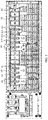
- FIG. 1 shows a schematic diagram of a copper bar connection mode when a UPS is in the three-phase input three-phase output, main path/bypass single-sourcing mode.
- the three-phase input three-phase output, main path/bypass single-sourcing mode shown in FIG. 1 is used by default when the UPS is delivered from a factory.
- FIG. 2 shows a schematic diagram of a copper bar connection mode when a UPS is in the three-phase input single-phase output, main path/bypass single-sourcing mode. It should be understood that parts in FIG.
- This application intends to provide an improved solution for switching an input/output mode of a UPS, to resolve a problem of a relatively high error rate of operations such as copper bar replacement and copper bar short-circuit during the switching of the input/output mode of the UPS.
- this application provides a copper bar component for switching an input/output mode of an uninterruptible power supply UPS.
- the UPS includes an enclosure of the UPS, an input or output wiring terminal is disposed on the enclosure of the UPS, and the input or output wiring terminal is in a single-phase or three-phase mode.
- the copper bar component includes at least one bracket and a plurality of copper bars, the plurality of copper bars are fastened to each of the at least one bracket, and the plurality of copper bars are connected to the input or output wiring terminal on the enclosure of the UPS.
- Each bracket is made of an insulating material.
- An arrangement manner of the plurality of copper bars on each bracket corresponds to one input or output mode of the UPS, and an arrangement manner of the plurality of copper bars on the at least one bracket is in a one-to-one correspondence with at least one input or output mode of the UPS, so as to switch the input or output mode of the UPS by replacing the copper bar component.
- the input mode of the UPS includes a single-phase or three-phase input mode
- the output mode of the UPS includes a single-phase or three-phase output mode.
- That the input or output wiring terminal is in a single-phase or three-phase mode may mean that the input wiring terminal may be in a single-phase or three-phase input mode after being short-circuited using the plurality of copper bars, and that the output wiring terminal may be in a single-phase or three-phase output mode after being short-circuited using the plurality of copper bars.
- the plurality of copper bars are fastened into a whole by using the bracket according to an arrangement manner corresponding to any input or output mode of the UPS, to form the copper bar component.
- a user may fasten the plurality of copper bars onto the enclosure of the UPS in a form of a copper bar component, to avoid prior-art risks of a copper bar replacement miss-out and a copper bar short-circuit error that are generated when the user manually disassembles or assembles a plurality of copper bars, thereby improving accuracy of copper bar replacement when the user switches the input/output mode of the UPS.
- a limiting hole is disposed on each of the plurality of copper bars, and a protruding part is disposed on each bracket; and the plurality of copper bars are fastened to each bracket by means of fitting between the limiting hole disposed on each copper bar and the protruding part disposed on each bracket.
- a copper bar component-based structural design is implemented by means of the fitting between the protruding part disposed on the bracket and the limiting hole disposed on the copper bar. This helps simplify an operation of on-site copper bar replacement by the user and improves efficiency of switching the input/output mode of the UPS.
- each bracket includes an upper bracket and a lower bracket, the protruding part is disposed on the upper bracket, and a limiting hole is disposed on the lower bracket; and the upper bracket is connected to the plurality of copper bars by using the protruding part, and the plurality of copper bars are fastened between the upper bracket and the lower bracket by means of fitting with the limiting hole disposed on the lower bracket.
- the copper bars are fastened between the upper bracket and the lower bracket by means of the fitting between the protruding part disposed on the upper bracket and the limiting hole disposed on the lower bracket, thereby improving the stability of a connection between the bracket and the copper bar.
- a label is disposed on each bracket, and the label is used to indicate an input or output mode, of the UPS, corresponding to each bracket.
- the label is disposed on the bracket, so that the user can identify the input/output mode corresponding to the UPS, thereby reducing complexity of switching the input/output mode of the UPS by the user and improving the efficiency of switching the input/output mode of the UPS.
- a foolproof structure is disposed on the at least one bracket and/or the enclosure of the UPS.
- the foolproof structure is disposed on the at least one bracket and/or the enclosure of the UPS, so as to reduce a probability of incorrectly switching the input/output mode of the UPS by the user.
- a protruding rib is disposed on each bracket, each bracket corresponds to one output mode of the UPS, a groove is disposed on the enclosure of the UPS, and the protruding rib and the groove form a foolproof structure; and the bracket corresponding to the output mode of the UPS and a bracket corresponding to the input mode of the UPS are differentiated by using fitting between the protruding rib of each bracket and the groove disposed on the enclosure of the UPS.
- the protruding rib disposed on the bracket corresponding to the output mode of the UPS and the groove disposed on the enclosure of the UPS are used as the foolproof structure, so as to differentiate between the bracket corresponding to the output mode of the UPS and the bracket corresponding to the input mode of the UPS. This prevents the user from installing the bracket corresponding to the output mode to an input port on the enclosure of the UPS, thereby improving accuracy of switching the input/output mode of the UPS by the user.
- a protruding rib is disposed on each bracket, each bracket corresponds to one input mode of the UPS, a groove is disposed on the enclosure of the UPS, and the protruding rib and the groove form a foolproof structure; and a bracket corresponding to the output mode of the UPS and the bracket corresponding to the input mode of the UPS are differentiated by using fitting between the protruding rib of each bracket and the groove disposed on the enclosure of the UPS.
- the protruding rib disposed on the bracket corresponding to the input mode of the UPS and the groove disposed on the enclosure of the UPS are used as the foolproof structure, so as to differentiate between the bracket corresponding to the output mode of the UPS and the bracket corresponding to the input mode of the UPS. This prevents the user from installing the bracket corresponding to the input mode to an output port on the enclosure of the UPS, thereby improving the accuracy of switching the input/output mode of the UPS by the user.
- a boss is disposed on a first bracket that is in the at least one bracket and that corresponds to a first mode of the UPS
- a boss is disposed on a second bracket that is in the at least one bracket and that corresponds to a second mode of the UPS
- the boss disposed on the first bracket and the boss disposed on the second bracket form a foolproof structure
- the first mode of the UPS is incompatible with the second mode of the UPS.
- the boss disposed on the bracket corresponding to the first mode of the UPS and the boss disposed on the bracket corresponding to the second mode of the UPS are used as the foolproof structure. This prevents machine explosion caused by installation of both the bracket corresponding to the first mode and the bracket corresponding to the second mode on the enclosure of the UPS by the user, thereby improving the accuracy of switching the input/output mode of the UPS by the user.
- the first mode is a three-phase input, main path/bypass single-sourcing mode
- the second mode is the single-phase output mode
- the boss disposed on the bracket corresponding to the three-phase input, main path/bypass single-sourcing mode of the UPS and the boss disposed on the bracket corresponding to the single-phase output mode of the UPS are used as the foolproof structure. This prevents machine explosion caused by installation of both the bracket corresponding to the three-phase input, main path/bypass single-sourcing mode and the bracket corresponding to the single-phase output mode on the enclosure of the UPS by the user, thereby improving the accuracy of switching the input/output mode of the UPS by the user.
- the plurality of copper bars are fastened to each bracket includes: the plurality of copper bars and each bracket are molded into one using a mold.
- the input port of the UPS power supply may be an input wiring terminal of the UPS power supply
- the output port of the UPS power supply may be an output wiring terminal of the UPS power supply
- the plurality of copper bars are fastened into a whole using the bracket in an arrangement manner corresponding to any input or output mode of the UPS, to form the copper bar component.
- the user can fasten the plurality of copper bars onto the enclosure of the UPS in the form of the copper bar component, thereby improving the accuracy of switching the input/output mode of the UPS by the user.
- a power system includes a UPS and a copper bar component, and the copper bar component includes any copper bar component according to the first aspect.
- a plurality of copper bars are fastened into a whole by using a bracket according to an arrangement manner corresponding to any input or output mode of the UPS, to form the copper bar component.
- a user may fasten the plurality of copper bars onto an enclosure of the UPS in a form of a copper bar component, to avoid prior-art risks of a copper bar replacement miss-out and a copper bar short-circuit error that are generated when the user manually disassembles or assembles a plurality of copper bars, thereby improving accuracy of copper bar replacement when the user switches the input/output mode of the UPS.
- FIG. 3 shows a schematic structural diagram of a copper bar component for switching an input/output mode of a UPS according to an embodiment of this application.
- a copper bar component 300 shown in FIG. 3 includes at least one bracket 310 and a plurality of copper bars 320. It should be understood that the copper bar component shown in FIG. 3 merely illustrates any bracket of the at least one bracket.
- the UPS includes an enclosure of the UPS, an input or output wiring terminal is disposed on the enclosure of the UPS, and the input or output wiring terminal is in a single-phase or three-phase mode.
- the copper bar component includes the at least one bracket and the plurality of copper bars, the plurality of copper bars are fastened to each of the at least one bracket, and the plurality of copper bars are connected to the input or output wiring terminal on the enclosure of the UPS.
- Each bracket is made of an insulating material.
- An arrangement manner of the plurality of copper bars on each bracket corresponds to one input or output mode of the UPS, and an arrangement manner of the plurality of copper bars on the at least one bracket is in a one-to-one correspondence with at least one input or output mode of the UPS, so as to switch the input or output mode of the UPS by replacing the copper bar component.
- the input mode of the UPS includes a single-phase or three-phase input mode
- the output mode of the UPS includes a single-phase or three-phase output mode.
- That the input or output wiring terminal is in a single-phase or three-phase mode may mean that the input wiring terminal may be in a single-phase or three-phase input mode after being short-circuited using the plurality of copper bars, and that the output wiring terminal may be in a single-phase or three-phase output mode after being short-circuited using the plurality of copper bars.
- the plurality of copper bars being fastened to each bracket may mean that the plurality of copper bars and the bracket are molded through insert molding in a plastic mold, or mean that the plurality of copper bars are connected to the bracket by using a connection mechanism such as a screw.
- a manner of a connection between the bracket and the plurality of copper bars is not specifically limited in this embodiment of this application.
- the plurality of copper bars are fastened into a whole by using the bracket according to an arrangement manner corresponding to any input or output mode of the UPS, to form the copper bar component.
- a user may fasten the plurality of copper bars onto the enclosure of the UPS in a form of a copper bar component, to avoid prior-art risks of a copper bar replacement miss-out and a copper bar short-circuit error that are generated when the user manually disassembles or assembles a plurality of copper bars, thereby improving accuracy of copper bar replacement when the user switches the input/output mode of the UPS.
- a limiting hole is disposed on each of the plurality of copper bars, and a protruding part is disposed on each bracket; and the plurality of copper bars are fastened to each bracket by means of fitting between the limiting hole disposed on each copper bar and the protruding part disposed on each bracket.
- a plurality of limiting holes may be disposed on each copper bar.
- a distance between two adjacent limiting holes on each copper bar may correspond to a model of the copper bar, that is, the distance between two adjacent limiting holes on the copper bar varies with the model, to reduce a rate of a copper bar installation error caused when a customer fastens the copper bars to the bracket.
- each copper bar may further have a different limiting hole shape or size, so as to differentiate between fastening positions of copper bars of different models on the bracket, that is, limiting holes of different shapes or sizes may be disposed on the copper bars of different models.
- a protruding part matching a limiting hole of a copper bar may be disposed on the bracket at an installation position of the corresponding copper bar, to reduce the rate of the copper bar installation error caused when the customer fastens the copper bars to the bracket.
- one limiting hole may be disposed on each copper bar.
- a quantity of limiting holes disposed on each copper bar is not specifically limited in this embodiment of this application.
- each bracket includes an upper bracket and a lower bracket, the protruding part is disposed on the upper bracket, and a limiting hole is disposed on the lower bracket.
- the upper bracket is connected to the plurality of copper bars by using the protruding part, and the plurality of copper bars are fastened between the upper bracket and the lower bracket by means of fitting with the limiting hole disposed on the lower bracket.
- a label is disposed on each bracket, and the label is used to indicate an input or output mode, of the UPS, corresponding to each bracket.
- FIG. 4 shows a schematic structural diagram of another copper bar component for switching an input/output mode of a UPS according to an embodiment of this application.
- a copper bar component 400 shown in FIG. 4 includes a label 410, a bracket, a plurality of copper bars 430, and a protruding part 440.
- the bracket may include an upper bracket 421 and a lower bracket 422.
- a protruding part disposed on the lower bracket 422 may fit with a limiting hole disposed on a copper bar, to fasten the copper bar to the lower bracket 422.
- the plurality of copper bars are then fastened between the upper bracket 421 and the lower bracket 422 through fitting between a fastening mechanism 450 disposed on the upper bracket 421 and a fastening hole 460 on the lower bracket 422.
- the label 410 may be further disposed on the upper bracket 421. The label is used to indicate an input or output mode, of the UPS, corresponding to each bracket, to facilitate identification by a user.
- the plurality of copper bars may be further fastened between the upper bracket and the lower bracket using screws. That is, a screw hole may be disposed on the upper bracket, and a screw hole may also be disposed on the lower bracket at a position corresponding to that on the upper bracket.
- the upper bracket may be fastened to the lower bracket using a screw, thereby fastening the copper bars between the upper bracket and the lower bracket.
- a connection relationship between the upper bracket and the lower bracket is not specifically limited in this embodiment of this application.
- the foregoing label may be fastened to the bracket by means of sticking, or may be a label integrally molded on the bracket when the bracket is molded using a plastic mold.
- a specific form of the label and a manner of a connection between the label and the bracket are not specifically limited in this embodiment of this application.
- a foolproof structure is disposed on the at least one bracket and/or the enclosure of the UPS.
- a groove may be disposed on a specific type of bracket in the at least one bracket and a protruding part may be disposed on the enclosure of the UPS, and the groove and the protruding part may fit with each other to form a foolproof structure.
- a protruding part may be disposed on a specific type of bracket in the at least one bracket and a groove may be disposed on the enclosure of the UPS, and the groove and the protruding part may fit with each other to form a foolproof structure.
- a protruding part may be disposed on a first specific type of bracket in the at least one bracket and a protruding part may be disposed on a second specific type of bracket in the at least one bracket, and a foolproof structure is formed by using the protruding part on the first type of bracket and the protruding part on the second type of bracket.
- An input/output mode corresponding to the first type of bracket is incompatible with an input/output mode corresponding to the second type of bracket.
- a form of the foregoing foolproof structure is not specifically limited in this application.
- a protruding rib is disposed on each bracket, each bracket corresponds to one output mode of the UPS, a groove is disposed on the enclosure of the UPS, and the protruding rib and the groove form a foolproof structure.
- the bracket corresponding to the output mode of the UPS and a bracket corresponding to the input mode of the UPS are differentiated by using fitting between the protruding rib of each bracket and the groove disposed on the enclosure of the UPS.
- a protruding rib is disposed on each bracket, each bracket corresponds to one input mode of the UPS, a groove is disposed on the enclosure of the UPS, and the protruding rib and the groove form a foolproof structure.
- a bracket corresponding to the output mode of the UPS and the bracket corresponding to the input mode of the UPS are differentiated by using fitting between the protruding rib of each bracket and the groove disposed on the enclosure of the UPS.
- FIG. 5 shows a schematic structural diagram of a foolproof structure on an enclosure of a UPS according to an embodiment of this application.
- a foolproof structure on an enclosure 500 of the UPS is disposed on a bracket corresponding to an input mode of the UPS. It should be understood that, alternatively, the foolproof structure may be disposed on a bracket corresponding to an output mode of the UPS.
- a protruding rib 520 is disposed on a bracket 510 of a copper bar component corresponding to an input port of the UPS, and a groove 530 is disposed on the enclosure of the UPS.
- the foregoing protruding rib and groove form the foolproof structure.
- the copper bar component corresponding to the input port When the copper bar component corresponding to the input port is to be installed on an output port of the UPS due to a user error, the copper bar component of the foregoing input port cannot be installed at a position of a copper bar component of the output port of the UPS because of the protruding rib disposed on the copper bar component corresponding to the input port. This prevents the user from mixing up the copper bar component corresponding to the input port of the UPS and the copper bar component corresponding to the output port of the UPS.
- the foregoing foolproof structure may be disposed on a copper bar component 540 corresponding to an output port. That is, a groove near the output port on the enclosure of the UPS fits with a protruding rib disposed on the copper bar component corresponding to the output port, to prevent a user from mixing up the copper bar component of the input port of the UPS and the copper bar component of the output port of the UPS.
- a position of the foregoing foolproof structure is not specifically limited in this embodiment of this application.
- the foolproof structure shown in FIG. 5 is illustrated as a rectangle merely as an example.
- a cross section of the protruding rib in the foregoing foolproof structure may be in a circular shape or the like.
- a shape of the protruding rib and a shape of the groove are not specifically limited in this embodiment of this application.
- a boss is disposed on a first bracket that is in the at least one bracket and that corresponds to a first mode of the UPS
- a boss is disposed on a second bracket that is in the at least one bracket and that corresponds to a second mode of the UPS
- the boss disposed on the first bracket and the boss disposed on the second bracket form a foolproof structure
- the first mode of the UPS is incompatible with the second mode of the UPS.
- FIG. 6 shows a schematic structural diagram of another foolproof structure on an enclosure of a UPS according to an embodiment of this application. It can be seen from an enclosure 600 of the UPS shown in FIG. 6 that, when a copper bar component installed on an output port of the UPS does not match a copper bar component to be installed on an input port of the UPS, that is, when an output mode corresponding to the copper bar component of the output port is incompatible with an input mode corresponding to the copper bar component of the input port, an interference phenomenon (referring to 610 shown in FIG. 6 ) occurs on a boss 620 disposed on the copper bar component installed on the output port and a boss 630 disposed on the copper bar component installed on the input port. Therefore, the copper bar component corresponding to the input mode and the copper bar component corresponding to the output mode incompatible with the input mode cannot be simultaneously installed on the UPS.
- an interference phenomenon referring to 610 shown in FIG. 6
- the bosses forming the foolproof structure may be another protruding structure.
- a structure and a shape of the boss are not specifically limited in this embodiment of this application.
- the first mode is a three-phase input, main path/bypass single-sourcing mode
- the second mode is the single-phase output mode
- FIG. 7 shows a schematic diagram of a power system according to an embodiment of this application.
- a power system 700 shown in FIG. 7 includes a UPS 710 and a copper bar component 720.
- the foregoing copper bar component may include any of the copper bar components shown in FIG. 3 to FIG. 6 .
- FIG. 7 shows a schematic diagram of a power system according to an embodiment of this application.
- a power system 700 shown in FIG. 7 includes a UPS 710 and a copper bar component 720.
- the foregoing copper bar component may include any of the copper bar components shown in FIG. 3 to FIG. 6 .
- FIG. 7 shows a schematic diagram of a power system according to an embodiment of this application.
- a power system 700 shown in FIG. 7 includes a UPS 710 and a copper bar component 720.
- the foregoing copper bar component may include any of the copper bar components shown in FIG. 3 to FIG. 6 .
- FIG. 7 shows a schematic diagram of a power system according to an embodiment of this application.
- the disclosed system, apparatus, and method may be implemented in other manners.
- the described apparatus embodiment is merely an example.
- the unit division is merely logical function division and may be other division in actual implementation.
- a plurality of units or components may be combined or integrated into another system, or some features may be ignored or not performed.
- the displayed or discussed mutual couplings or direct couplings or communication connections may be implemented through some interfaces, indirect couplings or communication connections between the apparatuses or units, or electrical connections, mechanical connections, or connections in other forms.
- the units described as separate parts may or may not be physically separate, and parts displayed as units may or may not be physical units, may be located in one position, or may be distributed on a plurality of network units. Some or all of the units may be selected according to actual needs to achieve the objectives of the solutions of the embodiments.
- the functions When the functions are implemented in the form of a software functional unit and sold or used as an independent product, the functions may be stored in a computer-readable storage medium. Based on such an understanding, the technical solutions of this application essentially, or the part contributing to the prior art, or some of the technical solutions may be implemented in a form of a software product.
- the software product is stored in a storage medium, and includes several instructions for instructing a computer device (which may be a personal computer, a server, or a network device) to perform all or some of the steps of the methods described in the embodiments of the present invention.
- the foregoing storage medium includes: any medium that can store program code, such as a USB flash drive, a removable hard disk, a read-only memory (Read-Only Memory, ROM), a random access memory (Random Access Memory, RAM), a magnetic disk, or an optical disc.
- program code such as a USB flash drive, a removable hard disk, a read-only memory (Read-Only Memory, ROM), a random access memory (Random Access Memory, RAM), a magnetic disk, or an optical disc.
Landscapes
- Engineering & Computer Science (AREA)
- Power Engineering (AREA)
- Microelectronics & Electronic Packaging (AREA)
- Computer Hardware Design (AREA)
- General Engineering & Computer Science (AREA)
- Business, Economics & Management (AREA)
- Emergency Management (AREA)
- Inverter Devices (AREA)
- Patch Boards (AREA)
Abstract
Description
- This application claims priority to Chinese Patent Application No.
201610892029.4 - This application claims priority to Chinese Patent Application No.
201621402624.7 - This application relates to the communications field, and in particular, to a copper bar component for switching an input/output mode of an uninterruptible power supply, and a power system.
- An uninterruptible power supply (Uninterruptible Power System/Uninterruptible Power Supply, UPS) is a system device that can connect a storage battery and a host, and convert a direct current into a mains supply by using a modular circuit such as an inverter of the host; and is mainly used to supply stable and uninterrupted electric power to a standalone computer, a computer network system, or another electric or electronic device such as a solenoid valve or a pressure transmitter. When mains input is normal, the UPS regulates a voltage of the mains supply and provides the mains supply to a load for use. In this case, the UPS is a voltage regulator for an alternating current mains supply, and may further charge a built-in battery at the same time. When the mains supply is interrupted (due to a forced power failure), the UPS immediately continues to supply a 220 V alternating current to the load by using direct current electric energy of the battery by means of a zero-switching conversion method using inversion, so that the load maintains normal operation, and software and hardware of the load are protected against damage. A UPS device can provide protection regardless whether a voltage is excessively high or excessively low.
- An input/output mode of the UPS includes single-phase and three-phase modes. To meet application requirements in different scenarios, besides switching recognition inside the UPS using hardware or software, a single-phase or three-phase conversion apparatus is also required at an input wiring terminal and an output wiring terminal of the UPS. A relatively commonly used method is to short-circuit ports of the UPS using a copper bar, thereby implementing switching between the three-phase mode and the single-phase mode. However, the UPS has a bypass. Therefore, wiring of input ports or output ports is relatively complex, and switching between the three-phase and single-phase input/output modes needs to be implemented by means of a short-circuit solution using copper bars of various models.
- In the prior art, the UPS can support four input/output modes: three-phase input three-phase output, main path/bypass single-sourcing; three-phase input three-phase output, main path/bypass different-sourcing; three-phase input single-phase output, main path/bypass single-sourcing; and three-phase input single-phase output, main path/bypass different-sourcing.
FIG. 1 shows a schematic diagram of a copper bar connection mode when a UPS is in the three-phase input three-phase output, main path/bypass single-sourcing mode. Generally, the three-phase input three-phase output, main path/bypass single-sourcing mode shown inFIG. 1 is used by default when the UPS is delivered from a factory. In the figure, mA, mB, mC, and mN represent main path input ports; bA, bB, bC, and bN represent bypass input ports; oA, oB, oC, and oN represent output ports; Bat+, Bat N, and Bat-represent power interfaces; and PE represents a ground port. When the input/output mode in factory settings of the UPS cannot meet an application requirement of a scenario, a user needs to manually replace copper bars one by one, to adapt to the application requirement of the scenario.FIG. 2 shows a schematic diagram of a copper bar connection mode when a UPS is in the three-phase input single-phase output, main path/bypass single-sourcing mode. It should be understood that parts inFIG. 2 that are the same as those inFIG. 1 use same sign descriptions as those forFIG. 1 . Details are not described herein again. In comparison with the copper bar connection mode shown inFIG. 1 , in the copper bar connection mode shown inFIG. 2 , a user needs to manually dismount four factory-default No. 3 copper bars of the UPS inFIG. 1 , and then fasten a total of six types of copper bars shown inFIG. 2 to an enclosure of the UPS using screws: two No. 4 copper bars, one No. 5 copper bar, one No. 6 copper bar, one No. 7 copper bar, one No. 8 copper bar, and one No. 10 copper bar. In the foregoing UPS input/output mode switching process, the copper bars are manually replaced one by one by the user. Therefore, a copper bar may be missed out and not replaced or a copper bar short-circuit error may occur in the copper bar replacement process. In this case, UPS explosion may be caused, and a risk thereof is uncontrollable. - This application intends to provide an improved solution for switching an input/output mode of a UPS, to resolve a problem of a relatively high error rate of operations such as copper bar replacement and copper bar short-circuit during the switching of the input/output mode of the UPS.
- According to a first aspect, this application provides a copper bar component for switching an input/output mode of an uninterruptible power supply UPS. The UPS includes an enclosure of the UPS, an input or output wiring terminal is disposed on the enclosure of the UPS, and the input or output wiring terminal is in a single-phase or three-phase mode. The copper bar component includes at least one bracket and a plurality of copper bars, the plurality of copper bars are fastened to each of the at least one bracket, and the plurality of copper bars are connected to the input or output wiring terminal on the enclosure of the UPS. Each bracket is made of an insulating material. An arrangement manner of the plurality of copper bars on each bracket corresponds to one input or output mode of the UPS, and an arrangement manner of the plurality of copper bars on the at least one bracket is in a one-to-one correspondence with at least one input or output mode of the UPS, so as to switch the input or output mode of the UPS by replacing the copper bar component. The input mode of the UPS includes a single-phase or three-phase input mode, and the output mode of the UPS includes a single-phase or three-phase output mode.
- That the input or output wiring terminal is in a single-phase or three-phase mode may mean that the input wiring terminal may be in a single-phase or three-phase input mode after being short-circuited using the plurality of copper bars, and that the output wiring terminal may be in a single-phase or three-phase output mode after being short-circuited using the plurality of copper bars.
- The plurality of copper bars are fastened into a whole by using the bracket according to an arrangement manner corresponding to any input or output mode of the UPS, to form the copper bar component. A user may fasten the plurality of copper bars onto the enclosure of the UPS in a form of a copper bar component, to avoid prior-art risks of a copper bar replacement miss-out and a copper bar short-circuit error that are generated when the user manually disassembles or assembles a plurality of copper bars, thereby improving accuracy of copper bar replacement when the user switches the input/output mode of the UPS.
- With reference to the first aspect, in a possible implementation of the first aspect, a limiting hole is disposed on each of the plurality of copper bars, and a protruding part is disposed on each bracket; and the plurality of copper bars are fastened to each bracket by means of fitting between the limiting hole disposed on each copper bar and the protruding part disposed on each bracket.
- A copper bar component-based structural design is implemented by means of the fitting between the protruding part disposed on the bracket and the limiting hole disposed on the copper bar. This helps simplify an operation of on-site copper bar replacement by the user and improves efficiency of switching the input/output mode of the UPS.
- With reference to either of the first aspect or the foregoing possible implementation, in another possible implementation of the first aspect, each bracket includes an upper bracket and a lower bracket, the protruding part is disposed on the upper bracket, and a limiting hole is disposed on the lower bracket; and the upper bracket is connected to the plurality of copper bars by using the protruding part, and the plurality of copper bars are fastened between the upper bracket and the lower bracket by means of fitting with the limiting hole disposed on the lower bracket.
- The copper bars are fastened between the upper bracket and the lower bracket by means of the fitting between the protruding part disposed on the upper bracket and the limiting hole disposed on the lower bracket, thereby improving the stability of a connection between the bracket and the copper bar.
- With reference to either of the first aspect or the foregoing possible implementation of the first aspect, in another possible implementation of the first aspect, a label is disposed on each bracket, and the label is used to indicate an input or output mode, of the UPS, corresponding to each bracket.
- The label is disposed on the bracket, so that the user can identify the input/output mode corresponding to the UPS, thereby reducing complexity of switching the input/output mode of the UPS by the user and improving the efficiency of switching the input/output mode of the UPS.
- With reference to either of the first aspect or the foregoing possible implementation of the first aspect, in another possible implementation of the first aspect, a foolproof structure is disposed on the at least one bracket and/or the enclosure of the UPS.
- The foolproof structure is disposed on the at least one bracket and/or the enclosure of the UPS, so as to reduce a probability of incorrectly switching the input/output mode of the UPS by the user.
- With reference to either of the first aspect or the foregoing possible implementation of the first aspect, in another possible implementation of the first aspect, a protruding rib is disposed on each bracket, each bracket corresponds to one output mode of the UPS, a groove is disposed on the enclosure of the UPS, and the protruding rib and the groove form a foolproof structure; and the bracket corresponding to the output mode of the UPS and a bracket corresponding to the input mode of the UPS are differentiated by using fitting between the protruding rib of each bracket and the groove disposed on the enclosure of the UPS.
- The protruding rib disposed on the bracket corresponding to the output mode of the UPS and the groove disposed on the enclosure of the UPS are used as the foolproof structure, so as to differentiate between the bracket corresponding to the output mode of the UPS and the bracket corresponding to the input mode of the UPS. This prevents the user from installing the bracket corresponding to the output mode to an input port on the enclosure of the UPS, thereby improving accuracy of switching the input/output mode of the UPS by the user.
- With reference to either of the first aspect or the foregoing possible implementation of the first aspect, in another possible implementation of the first aspect, a protruding rib is disposed on each bracket, each bracket corresponds to one input mode of the UPS, a groove is disposed on the enclosure of the UPS, and the protruding rib and the groove form a foolproof structure; and a bracket corresponding to the output mode of the UPS and the bracket corresponding to the input mode of the UPS are differentiated by using fitting between the protruding rib of each bracket and the groove disposed on the enclosure of the UPS.
- The protruding rib disposed on the bracket corresponding to the input mode of the UPS and the groove disposed on the enclosure of the UPS are used as the foolproof structure, so as to differentiate between the bracket corresponding to the output mode of the UPS and the bracket corresponding to the input mode of the UPS. This prevents the user from installing the bracket corresponding to the input mode to an output port on the enclosure of the UPS, thereby improving the accuracy of switching the input/output mode of the UPS by the user.
- With reference to any one of the first aspect or the foregoing possible implementations of the first aspect, in another possible implementation of the first aspect, a boss is disposed on a first bracket that is in the at least one bracket and that corresponds to a first mode of the UPS, a boss is disposed on a second bracket that is in the at least one bracket and that corresponds to a second mode of the UPS, the boss disposed on the first bracket and the boss disposed on the second bracket form a foolproof structure, and the first mode of the UPS is incompatible with the second mode of the UPS.
- The boss disposed on the bracket corresponding to the first mode of the UPS and the boss disposed on the bracket corresponding to the second mode of the UPS are used as the foolproof structure. This prevents machine explosion caused by installation of both the bracket corresponding to the first mode and the bracket corresponding to the second mode on the enclosure of the UPS by the user, thereby improving the accuracy of switching the input/output mode of the UPS by the user.
- With reference to any one of the first aspect or the foregoing possible implementations of the first aspect, in another possible implementation of the first aspect, the first mode is a three-phase input, main path/bypass single-sourcing mode, and the second mode is the single-phase output mode.
- The boss disposed on the bracket corresponding to the three-phase input, main path/bypass single-sourcing mode of the UPS and the boss disposed on the bracket corresponding to the single-phase output mode of the UPS are used as the foolproof structure. This prevents machine explosion caused by installation of both the bracket corresponding to the three-phase input, main path/bypass single-sourcing mode and the bracket corresponding to the single-phase output mode on the enclosure of the UPS by the user, thereby improving the accuracy of switching the input/output mode of the UPS by the user.
- With reference to either of the first aspect or the foregoing possible implementation of the first aspect, in another possible implementation of the first aspect, that the plurality of copper bars are fastened to each bracket includes: the plurality of copper bars and each bracket are molded into one using a mold.
- In some implementations, the input port of the UPS power supply may be an input wiring terminal of the UPS power supply, and the output port of the UPS power supply may be an output wiring terminal of the UPS power supply.
- In this embodiment of the present invention, the plurality of copper bars are fastened into a whole using the bracket in an arrangement manner corresponding to any input or output mode of the UPS, to form the copper bar component. In this way, the user can fasten the plurality of copper bars onto the enclosure of the UPS in the form of the copper bar component, thereby improving the accuracy of switching the input/output mode of the UPS by the user.
- According to a second aspect, a power system is provided. The power system includes a UPS and a copper bar component, and the copper bar component includes any copper bar component according to the first aspect.
- A plurality of copper bars are fastened into a whole by using a bracket according to an arrangement manner corresponding to any input or output mode of the UPS, to form the copper bar component. A user may fasten the plurality of copper bars onto an enclosure of the UPS in a form of a copper bar component, to avoid prior-art risks of a copper bar replacement miss-out and a copper bar short-circuit error that are generated when the user manually disassembles or assembles a plurality of copper bars, thereby improving accuracy of copper bar replacement when the user switches the input/output mode of the UPS.
-
-
FIG. 1 shows a schematic diagram of a copper bar connection mode when a UPS is in a three-phase input three-phase output, main path/bypass single-sourcing mode; -
FIG. 2 shows a schematic diagram of a copper bar connection mode when a UPS is in a three-phase input single-phase output, main path/bypass single-sourcing mode; -
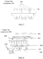
FIG. 3 shows a schematic structural diagram of a copper bar component for switching an input/output mode of a UPS according to an embodiment of this application; -
FIG. 4 shows a schematic structural diagram of another copper bar component for switching an input/output mode of a UPS according to an embodiment of this application; -
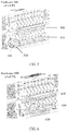
FIG. 5 shows a schematic structural diagram of a foolproof structure on an enclosure of a UPS according to an embodiment of this application; -
FIG. 6 shows a schematic structural diagram of another foolproof structure on an enclosure of a UPS according to an embodiment of this application; and -
FIG. 7 shows a schematic diagram of a power system according to an embodiment of this application. - The following describes technical solutions in embodiments of this application with reference to accompanying drawings.
-
FIG. 3 shows a schematic structural diagram of a copper bar component for switching an input/output mode of a UPS according to an embodiment of this application. Acopper bar component 300 shown inFIG. 3 includes at least onebracket 310 and a plurality of copper bars 320. It should be understood that the copper bar component shown inFIG. 3 merely illustrates any bracket of the at least one bracket. - The UPS includes an enclosure of the UPS, an input or output wiring terminal is disposed on the enclosure of the UPS, and the input or output wiring terminal is in a single-phase or three-phase mode. The copper bar component includes the at least one bracket and the plurality of copper bars, the plurality of copper bars are fastened to each of the at least one bracket, and the plurality of copper bars are connected to the input or output wiring terminal on the enclosure of the UPS. Each bracket is made of an insulating material. An arrangement manner of the plurality of copper bars on each bracket corresponds to one input or output mode of the UPS, and an arrangement manner of the plurality of copper bars on the at least one bracket is in a one-to-one correspondence with at least one input or output mode of the UPS, so as to switch the input or output mode of the UPS by replacing the copper bar component. The input mode of the UPS includes a single-phase or three-phase input mode, and the output mode of the UPS includes a single-phase or three-phase output mode.
- That the input or output wiring terminal is in a single-phase or three-phase mode may mean that the input wiring terminal may be in a single-phase or three-phase input mode after being short-circuited using the plurality of copper bars, and that the output wiring terminal may be in a single-phase or three-phase output mode after being short-circuited using the plurality of copper bars.
- It should be understood that, the plurality of copper bars being fastened to each bracket may mean that the plurality of copper bars and the bracket are molded through insert molding in a plastic mold, or mean that the plurality of copper bars are connected to the bracket by using a connection mechanism such as a screw. A manner of a connection between the bracket and the plurality of copper bars is not specifically limited in this embodiment of this application.
- The plurality of copper bars are fastened into a whole by using the bracket according to an arrangement manner corresponding to any input or output mode of the UPS, to form the copper bar component. A user may fasten the plurality of copper bars onto the enclosure of the UPS in a form of a copper bar component, to avoid prior-art risks of a copper bar replacement miss-out and a copper bar short-circuit error that are generated when the user manually disassembles or assembles a plurality of copper bars, thereby improving accuracy of copper bar replacement when the user switches the input/output mode of the UPS.
- Optionally, in an embodiment, a limiting hole is disposed on each of the plurality of copper bars, and a protruding part is disposed on each bracket; and the plurality of copper bars are fastened to each bracket by means of fitting between the limiting hole disposed on each copper bar and the protruding part disposed on each bracket.
- Specifically, a plurality of limiting holes may be disposed on each copper bar. A distance between two adjacent limiting holes on each copper bar may correspond to a model of the copper bar, that is, the distance between two adjacent limiting holes on the copper bar varies with the model, to reduce a rate of a copper bar installation error caused when a customer fastens the copper bars to the bracket.
- It should be understood that, each copper bar may further have a different limiting hole shape or size, so as to differentiate between fastening positions of copper bars of different models on the bracket, that is, limiting holes of different shapes or sizes may be disposed on the copper bars of different models. In addition, a protruding part matching a limiting hole of a copper bar may be disposed on the bracket at an installation position of the corresponding copper bar, to reduce the rate of the copper bar installation error caused when the customer fastens the copper bars to the bracket.
- It should be further understood that, one limiting hole may be disposed on each copper bar. A quantity of limiting holes disposed on each copper bar is not specifically limited in this embodiment of this application.
- Optionally, in an embodiment, each bracket includes an upper bracket and a lower bracket, the protruding part is disposed on the upper bracket, and a limiting hole is disposed on the lower bracket. The upper bracket is connected to the plurality of copper bars by using the protruding part, and the plurality of copper bars are fastened between the upper bracket and the lower bracket by means of fitting with the limiting hole disposed on the lower bracket.
- Optionally, in an embodiment, a label is disposed on each bracket, and the label is used to indicate an input or output mode, of the UPS, corresponding to each bracket.
- Specifically,
FIG. 4 shows a schematic structural diagram of another copper bar component for switching an input/output mode of a UPS according to an embodiment of this application. Acopper bar component 400 shown inFIG. 4 includes alabel 410, a bracket, a plurality ofcopper bars 430, and aprotruding part 440. The bracket may include anupper bracket 421 and alower bracket 422. A protruding part disposed on thelower bracket 422 may fit with a limiting hole disposed on a copper bar, to fasten the copper bar to thelower bracket 422. The plurality of copper bars are then fastened between theupper bracket 421 and thelower bracket 422 through fitting between afastening mechanism 450 disposed on theupper bracket 421 and afastening hole 460 on thelower bracket 422. Thelabel 410 may be further disposed on theupper bracket 421. The label is used to indicate an input or output mode, of the UPS, corresponding to each bracket, to facilitate identification by a user. - It should be understood that the plurality of copper bars may be further fastened between the upper bracket and the lower bracket using screws. That is, a screw hole may be disposed on the upper bracket, and a screw hole may also be disposed on the lower bracket at a position corresponding to that on the upper bracket. When the copper bars are fastened to the lower bracket using the protruding part disposed on the lower bracket, the upper bracket may be fastened to the lower bracket using a screw, thereby fastening the copper bars between the upper bracket and the lower bracket. A connection relationship between the upper bracket and the lower bracket is not specifically limited in this embodiment of this application.
- It should be further understood that, the foregoing label may be fastened to the bracket by means of sticking, or may be a label integrally molded on the bracket when the bracket is molded using a plastic mold. A specific form of the label and a manner of a connection between the label and the bracket are not specifically limited in this embodiment of this application.
- Optionally, in an embodiment, a foolproof structure is disposed on the at least one bracket and/or the enclosure of the UPS.
- It should be understood that, a groove may be disposed on a specific type of bracket in the at least one bracket and a protruding part may be disposed on the enclosure of the UPS, and the groove and the protruding part may fit with each other to form a foolproof structure. Alternatively, a protruding part may be disposed on a specific type of bracket in the at least one bracket and a groove may be disposed on the enclosure of the UPS, and the groove and the protruding part may fit with each other to form a foolproof structure. Alternatively, a protruding part may be disposed on a first specific type of bracket in the at least one bracket and a protruding part may be disposed on a second specific type of bracket in the at least one bracket, and a foolproof structure is formed by using the protruding part on the first type of bracket and the protruding part on the second type of bracket. An input/output mode corresponding to the first type of bracket is incompatible with an input/output mode corresponding to the second type of bracket. A form of the foregoing foolproof structure is not specifically limited in this application.
- Optionally, in an embodiment, a protruding rib is disposed on each bracket, each bracket corresponds to one output mode of the UPS, a groove is disposed on the enclosure of the UPS, and the protruding rib and the groove form a foolproof structure. The bracket corresponding to the output mode of the UPS and a bracket corresponding to the input mode of the UPS are differentiated by using fitting between the protruding rib of each bracket and the groove disposed on the enclosure of the UPS.
- Optionally, in an embodiment, a protruding rib is disposed on each bracket, each bracket corresponds to one input mode of the UPS, a groove is disposed on the enclosure of the UPS, and the protruding rib and the groove form a foolproof structure. A bracket corresponding to the output mode of the UPS and the bracket corresponding to the input mode of the UPS are differentiated by using fitting between the protruding rib of each bracket and the groove disposed on the enclosure of the UPS.
- Specifically,
FIG. 5 shows a schematic structural diagram of a foolproof structure on an enclosure of a UPS according to an embodiment of this application. In an example shown inFIG. 5 , a foolproof structure on anenclosure 500 of the UPS is disposed on a bracket corresponding to an input mode of the UPS. It should be understood that, alternatively, the foolproof structure may be disposed on a bracket corresponding to an output mode of the UPS. As shown inFIG. 5 , a protrudingrib 520 is disposed on abracket 510 of a copper bar component corresponding to an input port of the UPS, and agroove 530 is disposed on the enclosure of the UPS. The foregoing protruding rib and groove form the foolproof structure. When the copper bar component corresponding to the input port is to be installed on an output port of the UPS due to a user error, the copper bar component of the foregoing input port cannot be installed at a position of a copper bar component of the output port of the UPS because of the protruding rib disposed on the copper bar component corresponding to the input port. This prevents the user from mixing up the copper bar component corresponding to the input port of the UPS and the copper bar component corresponding to the output port of the UPS. - It should be understood that, alternatively, the foregoing foolproof structure may be disposed on a
copper bar component 540 corresponding to an output port. That is, a groove near the output port on the enclosure of the UPS fits with a protruding rib disposed on the copper bar component corresponding to the output port, to prevent a user from mixing up the copper bar component of the input port of the UPS and the copper bar component of the output port of the UPS. A position of the foregoing foolproof structure is not specifically limited in this embodiment of this application. - It should be further understood that, the foolproof structure shown in
FIG. 5 is illustrated as a rectangle merely as an example. Alternatively, a cross section of the protruding rib in the foregoing foolproof structure may be in a circular shape or the like. A shape of the protruding rib and a shape of the groove are not specifically limited in this embodiment of this application. - Optionally, in an embodiment, a boss is disposed on a first bracket that is in the at least one bracket and that corresponds to a first mode of the UPS, a boss is disposed on a second bracket that is in the at least one bracket and that corresponds to a second mode of the UPS, the boss disposed on the first bracket and the boss disposed on the second bracket form a foolproof structure, and the first mode of the UPS is incompatible with the second mode of the UPS.
- Specifically,
FIG. 6 shows a schematic structural diagram of another foolproof structure on an enclosure of a UPS according to an embodiment of this application. It can be seen from anenclosure 600 of the UPS shown inFIG. 6 that, when a copper bar component installed on an output port of the UPS does not match a copper bar component to be installed on an input port of the UPS, that is, when an output mode corresponding to the copper bar component of the output port is incompatible with an input mode corresponding to the copper bar component of the input port, an interference phenomenon (referring to 610 shown inFIG. 6 ) occurs on aboss 620 disposed on the copper bar component installed on the output port and aboss 630 disposed on the copper bar component installed on the input port. Therefore, the copper bar component corresponding to the input mode and the copper bar component corresponding to the output mode incompatible with the input mode cannot be simultaneously installed on the UPS. - It should be understood that, alternatively, the bosses forming the foolproof structure may be another protruding structure. A structure and a shape of the boss are not specifically limited in this embodiment of this application.
- Optionally, in an embodiment, the first mode is a three-phase input, main path/bypass single-sourcing mode, and the second mode is the single-phase output mode.
-
FIG. 7 shows a schematic diagram of a power system according to an embodiment of this application. A power system 700 shown inFIG. 7 includes aUPS 710 and acopper bar component 720. It should be understood that, the foregoing copper bar component may include any of the copper bar components shown inFIG. 3 to FIG. 6 . For brevity, details are not described herein again. - In the several embodiments provided in this application, it should be understood that the disclosed system, apparatus, and method may be implemented in other manners. For example, the described apparatus embodiment is merely an example. For example, the unit division is merely logical function division and may be other division in actual implementation. For example, a plurality of units or components may be combined or integrated into another system, or some features may be ignored or not performed. In addition, the displayed or discussed mutual couplings or direct couplings or communication connections may be implemented through some interfaces, indirect couplings or communication connections between the apparatuses or units, or electrical connections, mechanical connections, or connections in other forms.
- The units described as separate parts may or may not be physically separate, and parts displayed as units may or may not be physical units, may be located in one position, or may be distributed on a plurality of network units. Some or all of the units may be selected according to actual needs to achieve the objectives of the solutions of the embodiments.
- In addition, functional units in the embodiments of this application may be integrated into one processing unit, or each of the units may exist alone physically, or two or more units are integrated into one unit.
- When the functions are implemented in the form of a software functional unit and sold or used as an independent product, the functions may be stored in a computer-readable storage medium. Based on such an understanding, the technical solutions of this application essentially, or the part contributing to the prior art, or some of the technical solutions may be implemented in a form of a software product. The software product is stored in a storage medium, and includes several instructions for instructing a computer device (which may be a personal computer, a server, or a network device) to perform all or some of the steps of the methods described in the embodiments of the present invention. The foregoing storage medium includes: any medium that can store program code, such as a USB flash drive, a removable hard disk, a read-only memory (Read-Only Memory, ROM), a random access memory (Random Access Memory, RAM), a magnetic disk, or an optical disc.
Claims (11)
- A copper bar component for switching an input/output mode of an uninterruptible power supply, wherein the uninterruptible power supply UPS comprises an enclosure of the UPS, an input or output wiring terminal is disposed on the enclosure of the UPS, and the input or output wiring terminal is in a single-phase or three-phase mode;
the copper bar component comprises at least one bracket and a plurality of copper bars, the plurality of copper bars are fastened to each of the at least one bracket, and the plurality of copper bars are configured to connect to the input or output wiring terminal on the enclosure of the UPS; and
each bracket is made of an insulating material, and an arrangement manner of the plurality of copper bars on the at least one bracket corresponds to at least one input or output mode of the UPS, so as to switch the input or output mode of the UPS by replacing the copper bar component, wherein the input mode of the UPS comprises a single-phase or three-phase input mode, and the output mode of the UPS comprises a single-phase or three-phase output mode. - The copper bar component according to claim 1, wherein a limiting hole is disposed on each of the plurality of copper bars, and a protruding part is disposed on each bracket; and
the plurality of copper bars are fastened to each bracket by means of fitting between the limiting hole disposed on each copper bar and the protruding part disposed on each bracket. - The copper bar component according to claim 2, wherein each bracket comprises an upper bracket and a lower bracket, the protruding part is disposed on the upper bracket, and a limiting hole is disposed on the lower bracket; and
the upper bracket is connected to the plurality of copper bars by using the protruding part, and the plurality of copper bars are fastened between the upper bracket and the lower bracket by means of fitting with the limiting hole disposed on the lower bracket. - The copper bar component according to claim 1, wherein a label is disposed on each bracket, and the label is used to indicate an input or output mode, of the UPS, corresponding to each bracket.
- The copper bar component according to claim 1, wherein a foolproof structure is disposed on the at least one bracket and/or the enclosure of the UPS.
- The copper bar component according to claim 1, wherein a protruding rib is disposed on each bracket, each bracket corresponds to one output mode of the UPS, a groove is disposed on the enclosure of the UPS, and the protruding rib and the groove form a foolproof structure; and
the bracket corresponding to the output mode of the UPS and a bracket corresponding to the input mode of the UPS are differentiated by using fitting between the protruding rib of each bracket and the groove disposed on the enclosure of the UPS. - The copper bar component according to claim 1, wherein a protruding rib is disposed on each bracket, each bracket corresponds to one input mode of the UPS, a groove is disposed on the enclosure of the UPS, and the protruding rib and the groove form a foolproof structure; and
a bracket corresponding to the output mode of the UPS and the bracket corresponding to the input mode of the UPS are differentiated by using fitting between the protruding rib of each bracket and the groove disposed on the enclosure of the UPS. - The copper bar component according to any one of claims 1 to 7, wherein a boss is disposed on a first bracket that is in the at least one bracket and that corresponds to a first mode of the UPS, a boss is disposed on a second bracket that is in the at least one bracket and that corresponds to a second mode of the UPS, the boss disposed on the first bracket and the boss disposed on the second bracket form a foolproof structure, and the first mode of the UPS is incompatible with the second mode of the UPS.
- The copper bar component according to claim 8, wherein the first mode is a three-phase input, main path/bypass single-sourcing mode, and the second mode is the single-phase output mode.
- The copper bar component according to claim 1, wherein that the plurality of copper bars are fastened to each bracket comprises:
the plurality of copper bars and each bracket are molded into one using a mold. - A power system, comprising an uninterruptible power supply UPS and a copper bar component, wherein the copper bar component comprises the copper bar component according to any one of claims 1 to 10.
Applications Claiming Priority (3)
| Application Number | Priority Date | Filing Date | Title |
|---|---|---|---|
| CN201610892029 | 2016-10-12 | ||
| CN201621402624.7U CN206673335U (en) | 2016-10-12 | 2016-12-20 | Copper bar component and electric power system for switching uninterrupted power supply input and output mode |
| PCT/CN2017/105548 WO2018068706A1 (en) | 2016-10-12 | 2017-10-10 | Copper strip assembly and power supply system for switching input and output modes of uninterruptible power supply |
Publications (3)
| Publication Number | Publication Date |
|---|---|
| EP3512055A1 true EP3512055A1 (en) | 2019-07-17 |
| EP3512055A4 EP3512055A4 (en) | 2019-10-02 |
| EP3512055B1 EP3512055B1 (en) | 2021-05-26 |
Family
ID=60357765
Family Applications (1)
| Application Number | Title | Priority Date | Filing Date |
|---|---|---|---|
| EP17860507.7A Active EP3512055B1 (en) | 2016-10-12 | 2017-10-10 | Copper strip assembly and power supply system for switching input and output modes of uninterruptible power supply |
Country Status (4)
| Country | Link |
|---|---|
| US (1) | US10826282B2 (en) |
| EP (1) | EP3512055B1 (en) |
| CN (1) | CN206673335U (en) |
| WO (1) | WO2018068706A1 (en) |
Families Citing this family (2)
| Publication number | Priority date | Publication date | Assignee | Title |
|---|---|---|---|---|
| USD867300S1 (en) * | 2017-11-30 | 2019-11-19 | Delta Electronics, Inc. | Electrical bus bar assembly |
| CN108829401B (en) * | 2018-05-21 | 2021-02-09 | 全球能源互联网研究院有限公司 | Monitoring mode switching method, device, terminal and readable storage medium |
Family Cites Families (14)
| Publication number | Priority date | Publication date | Assignee | Title |
|---|---|---|---|---|
| CN2196833Y (en) * | 1994-08-30 | 1995-05-10 | 柯登利 | Safety low-voltage collecting-raw base group for distribution panel |
| CN2293910Y (en) * | 1997-02-12 | 1998-10-07 | 简永昌 | Cassette distribution box |
| US6442017B1 (en) * | 2000-08-09 | 2002-08-27 | Server Technology, Inc. | Battery-power distribution panel for network equipment |
| US7281958B2 (en) * | 2004-01-23 | 2007-10-16 | American Power Conversion Corporation | Power terminal block |
| US7781914B2 (en) * | 2007-08-10 | 2010-08-24 | American Power Conversion Corporation | Input and output power modules configured to provide selective power to an uninterruptible power supply |
| US8223476B2 (en) * | 2008-02-21 | 2012-07-17 | Siemens Industry, Inc. | Field rephaseable modular metering devices |
| TWI493328B (en) * | 2009-10-02 | 2015-07-21 | Delta Electronics Inc | Power distribution unit for receiving multiple types of three and one phase power sources |
| JP2011182504A (en) * | 2010-02-26 | 2011-09-15 | Nitto Electric Works Ltd | Unit for dc power supply distribution and distribution panel for dc power supply |
| US8546689B2 (en) * | 2011-02-24 | 2013-10-01 | Schneider Electric It Corporation | Service access point for a uninterruptible power supply |
| CN202042803U (en) * | 2011-03-29 | 2011-11-16 | 力博特公司 | Uninterrupted power supply (UPS) system customer wiring device |
| CN202103565U (en) * | 2011-06-17 | 2012-01-04 | 力博特公司 | Static switch cabinet |
| US8987618B2 (en) * | 2012-06-05 | 2015-03-24 | Siemens Industry, Inc. | Non-load break isolating switch, voltage controllers, and assembly methods |
| JP6263311B2 (en) * | 2015-03-31 | 2018-01-17 | 日立オートモティブシステムズ株式会社 | Power converter |
| CN205029275U (en) * | 2015-10-10 | 2016-02-10 | 东莞基业电气设备有限公司 | A four-pole circuit breaker installation assembly for a distribution box |
-
2016
- 2016-12-20 CN CN201621402624.7U patent/CN206673335U/en active Active
-
2017
- 2017-10-10 EP EP17860507.7A patent/EP3512055B1/en active Active
- 2017-10-10 WO PCT/CN2017/105548 patent/WO2018068706A1/en not_active Ceased
-
2019
- 2019-04-12 US US16/382,576 patent/US10826282B2/en active Active
Also Published As
| Publication number | Publication date |
|---|---|
| US20190237948A1 (en) | 2019-08-01 |
| EP3512055B1 (en) | 2021-05-26 |
| WO2018068706A1 (en) | 2018-04-19 |
| EP3512055A4 (en) | 2019-10-02 |
| US10826282B2 (en) | 2020-11-03 |
| CN206673335U (en) | 2017-11-24 |
Similar Documents
| Publication | Publication Date | Title |
|---|---|---|
| US11581588B2 (en) | Energy storage system | |
| CN113826295B (en) | Intelligent automatic transfer switch module | |
| EP3309920B1 (en) | Method and device for voltage balance | |
| TWI342096B (en) | Switching power supply unit and disk array system | |
| AU2013201985B2 (en) | Power module system | |
| US12068624B2 (en) | System and method for controlling an electrical receptacle | |
| US20100187908A1 (en) | Maintenance Bypass Device | |
| CN109710046A (en) | Electric control system, method, apparatus and master control borad above and below frame type equipment business board | |
| US10826282B2 (en) | Copper bar component for switching input/output mode of uninterruptible power supply, and power system | |
| US12184067B2 (en) | Communication power supply system | |
| EP3890130B1 (en) | Power distribution apparatus and power distribution system | |
| CN107785940A (en) | The method for controlling power supply of more battery module parallel configurations | |
| US8443215B2 (en) | Power booster and electronic system using same | |
| CN110445229A (en) | Energy storage power supply | |
| CN113363847A (en) | Intelligent UPS power distribution device for data center power distribution and rapid installation method thereof | |
| CN107479611B (en) | A kind of communication equipment and electrification control method | |
| CN100454711C (en) | Method and device for battery undervoltage protection | |
| US9247665B2 (en) | Uninterruptible power supply with a power isolation circuit loop | |
| CN105870520A (en) | Control method, device and system of lithium battery | |
| CN207743357U (en) | It is a kind of to prevent UPS from reporting alarm device by mistake applied to large-scale lithium ion battery | |
| CN206100074U (en) | A long -range switch control system for carbone controller | |
| CN214380285U (en) | Power supply device | |
| US9800065B2 (en) | Charging system and equipment and method thereof | |
| CN105333561A (en) | Electronic control panel, method for operating electronic control panel and electronic device | |
| CN221308109U (en) | Cleaning robot's identification circuit and cleaning robot |
Legal Events
| Date | Code | Title | Description |
|---|---|---|---|
| STAA | Information on the status of an ep patent application or granted ep patent |
Free format text: STATUS: THE INTERNATIONAL PUBLICATION HAS BEEN MADE |
|
| PUAI | Public reference made under article 153(3) epc to a published international application that has entered the european phase |
Free format text: ORIGINAL CODE: 0009012 |
|
| STAA | Information on the status of an ep patent application or granted ep patent |
Free format text: STATUS: REQUEST FOR EXAMINATION WAS MADE |
|
| 17P | Request for examination filed |
Effective date: 20190412 |
|
| AK | Designated contracting states |
Kind code of ref document: A1 Designated state(s): AL AT BE BG CH CY CZ DE DK EE ES FI FR GB GR HR HU IE IS IT LI LT LU LV MC MK MT NL NO PL PT RO RS SE SI SK SM TR |
|
| AX | Request for extension of the european patent |
Extension state: BA ME |
|
| A4 | Supplementary search report drawn up and despatched |
Effective date: 20190829 |
|
| RIC1 | Information provided on ipc code assigned before grant |
Ipc: H05K 7/14 20060101ALI20190823BHEP Ipc: H02B 1/20 20060101AFI20190823BHEP Ipc: H01B 5/02 20060101ALI20190823BHEP |
|
| DAV | Request for validation of the european patent (deleted) | ||
| DAX | Request for extension of the european patent (deleted) | ||
| STAA | Information on the status of an ep patent application or granted ep patent |
Free format text: STATUS: EXAMINATION IS IN PROGRESS |
|
| 17Q | First examination report despatched |
Effective date: 20200702 |
|
| GRAP | Despatch of communication of intention to grant a patent |
Free format text: ORIGINAL CODE: EPIDOSNIGR1 |
|
| STAA | Information on the status of an ep patent application or granted ep patent |
Free format text: STATUS: GRANT OF PATENT IS INTENDED |
|
| INTG | Intention to grant announced |
Effective date: 20210122 |
|
| GRAS | Grant fee paid |
Free format text: ORIGINAL CODE: EPIDOSNIGR3 |
|
| GRAA | (expected) grant |
Free format text: ORIGINAL CODE: 0009210 |
|
| STAA | Information on the status of an ep patent application or granted ep patent |
Free format text: STATUS: THE PATENT HAS BEEN GRANTED |
|
| AK | Designated contracting states |
Kind code of ref document: B1 Designated state(s): AL AT BE BG CH CY CZ DE DK EE ES FI FR GB GR HR HU IE IS IT LI LT LU LV MC MK MT NL NO PL PT RO RS SE SI SK SM TR |
|
| REG | Reference to a national code |
Ref country code: GB Ref legal event code: FG4D |
|
| REG | Reference to a national code |
Ref country code: CH Ref legal event code: EP |
|
| REG | Reference to a national code |
Ref country code: DE Ref legal event code: R096 Ref document number: 602017039460 Country of ref document: DE |
|
| REG | Reference to a national code |
Ref country code: AT Ref legal event code: REF Ref document number: 1397187 Country of ref document: AT Kind code of ref document: T Effective date: 20210615 |
|
| REG | Reference to a national code |
Ref country code: IE Ref legal event code: FG4D |
|
| REG | Reference to a national code |
Ref country code: LT Ref legal event code: MG9D |
|
| REG | Reference to a national code |
Ref country code: AT Ref legal event code: MK05 Ref document number: 1397187 Country of ref document: AT Kind code of ref document: T Effective date: 20210526 |
|
| PG25 | Lapsed in a contracting state [announced via postgrant information from national office to epo] |
Ref country code: BG Free format text: LAPSE BECAUSE OF FAILURE TO SUBMIT A TRANSLATION OF THE DESCRIPTION OR TO PAY THE FEE WITHIN THE PRESCRIBED TIME-LIMIT Effective date: 20210826 Ref country code: AT Free format text: LAPSE BECAUSE OF FAILURE TO SUBMIT A TRANSLATION OF THE DESCRIPTION OR TO PAY THE FEE WITHIN THE PRESCRIBED TIME-LIMIT Effective date: 20210526 Ref country code: HR Free format text: LAPSE BECAUSE OF FAILURE TO SUBMIT A TRANSLATION OF THE DESCRIPTION OR TO PAY THE FEE WITHIN THE PRESCRIBED TIME-LIMIT Effective date: 20210526 Ref country code: FI Free format text: LAPSE BECAUSE OF FAILURE TO SUBMIT A TRANSLATION OF THE DESCRIPTION OR TO PAY THE FEE WITHIN THE PRESCRIBED TIME-LIMIT Effective date: 20210526 Ref country code: LT Free format text: LAPSE BECAUSE OF FAILURE TO SUBMIT A TRANSLATION OF THE DESCRIPTION OR TO PAY THE FEE WITHIN THE PRESCRIBED TIME-LIMIT Effective date: 20210526 |
|
| REG | Reference to a national code |
Ref country code: NL Ref legal event code: MP Effective date: 20210526 |
|
| PG25 | Lapsed in a contracting state [announced via postgrant information from national office to epo] |
Ref country code: GR Free format text: LAPSE BECAUSE OF FAILURE TO SUBMIT A TRANSLATION OF THE DESCRIPTION OR TO PAY THE FEE WITHIN THE PRESCRIBED TIME-LIMIT Effective date: 20210827 Ref country code: IS Free format text: LAPSE BECAUSE OF FAILURE TO SUBMIT A TRANSLATION OF THE DESCRIPTION OR TO PAY THE FEE WITHIN THE PRESCRIBED TIME-LIMIT Effective date: 20210926 Ref country code: SE Free format text: LAPSE BECAUSE OF FAILURE TO SUBMIT A TRANSLATION OF THE DESCRIPTION OR TO PAY THE FEE WITHIN THE PRESCRIBED TIME-LIMIT Effective date: 20210526 Ref country code: RS Free format text: LAPSE BECAUSE OF FAILURE TO SUBMIT A TRANSLATION OF THE DESCRIPTION OR TO PAY THE FEE WITHIN THE PRESCRIBED TIME-LIMIT Effective date: 20210526 Ref country code: LV Free format text: LAPSE BECAUSE OF FAILURE TO SUBMIT A TRANSLATION OF THE DESCRIPTION OR TO PAY THE FEE WITHIN THE PRESCRIBED TIME-LIMIT Effective date: 20210526 Ref country code: PL Free format text: LAPSE BECAUSE OF FAILURE TO SUBMIT A TRANSLATION OF THE DESCRIPTION OR TO PAY THE FEE WITHIN THE PRESCRIBED TIME-LIMIT Effective date: 20210526 Ref country code: PT Free format text: LAPSE BECAUSE OF FAILURE TO SUBMIT A TRANSLATION OF THE DESCRIPTION OR TO PAY THE FEE WITHIN THE PRESCRIBED TIME-LIMIT Effective date: 20210927 Ref country code: NO Free format text: LAPSE BECAUSE OF FAILURE TO SUBMIT A TRANSLATION OF THE DESCRIPTION OR TO PAY THE FEE WITHIN THE PRESCRIBED TIME-LIMIT Effective date: 20210826 |
|
| RAP2 | Party data changed (patent owner data changed or rights of a patent transferred) |
Owner name: HUAWEI DIGITAL POWER TECHNOLOGIES CO., LTD. |
|
| REG | Reference to a national code |
Ref country code: DE Ref legal event code: R081 Ref document number: 602017039460 Country of ref document: DE Owner name: HUAWEI DIGITAL POWER TECHNOLOGIES CO., LTD., S, CN Free format text: FORMER OWNER: HUAWEI TECHNOLOGIES CO., LTD., SHENZHEN, GUANGDONG, CN |
|
| PG25 | Lapsed in a contracting state [announced via postgrant information from national office to epo] |
Ref country code: NL Free format text: LAPSE BECAUSE OF FAILURE TO SUBMIT A TRANSLATION OF THE DESCRIPTION OR TO PAY THE FEE WITHIN THE PRESCRIBED TIME-LIMIT Effective date: 20210526 |
|
| PG25 | Lapsed in a contracting state [announced via postgrant information from national office to epo] |
Ref country code: SK Free format text: LAPSE BECAUSE OF FAILURE TO SUBMIT A TRANSLATION OF THE DESCRIPTION OR TO PAY THE FEE WITHIN THE PRESCRIBED TIME-LIMIT Effective date: 20210526 Ref country code: SM Free format text: LAPSE BECAUSE OF FAILURE TO SUBMIT A TRANSLATION OF THE DESCRIPTION OR TO PAY THE FEE WITHIN THE PRESCRIBED TIME-LIMIT Effective date: 20210526 Ref country code: EE Free format text: LAPSE BECAUSE OF FAILURE TO SUBMIT A TRANSLATION OF THE DESCRIPTION OR TO PAY THE FEE WITHIN THE PRESCRIBED TIME-LIMIT Effective date: 20210526 Ref country code: ES Free format text: LAPSE BECAUSE OF FAILURE TO SUBMIT A TRANSLATION OF THE DESCRIPTION OR TO PAY THE FEE WITHIN THE PRESCRIBED TIME-LIMIT Effective date: 20210526 Ref country code: DK Free format text: LAPSE BECAUSE OF FAILURE TO SUBMIT A TRANSLATION OF THE DESCRIPTION OR TO PAY THE FEE WITHIN THE PRESCRIBED TIME-LIMIT Effective date: 20210526 Ref country code: CZ Free format text: LAPSE BECAUSE OF FAILURE TO SUBMIT A TRANSLATION OF THE DESCRIPTION OR TO PAY THE FEE WITHIN THE PRESCRIBED TIME-LIMIT Effective date: 20210526 Ref country code: RO Free format text: LAPSE BECAUSE OF FAILURE TO SUBMIT A TRANSLATION OF THE DESCRIPTION OR TO PAY THE FEE WITHIN THE PRESCRIBED TIME-LIMIT Effective date: 20210526 |
|
| REG | Reference to a national code |
Ref country code: DE Ref legal event code: R097 Ref document number: 602017039460 Country of ref document: DE |
|
| PLBE | No opposition filed within time limit |
Free format text: ORIGINAL CODE: 0009261 |
|
| STAA | Information on the status of an ep patent application or granted ep patent |
Free format text: STATUS: NO OPPOSITION FILED WITHIN TIME LIMIT |
|
| 26N | No opposition filed |
Effective date: 20220301 |
|
| REG | Reference to a national code |
Ref country code: CH Ref legal event code: PL |
|
| PG25 | Lapsed in a contracting state [announced via postgrant information from national office to epo] |
Ref country code: IS Free format text: LAPSE BECAUSE OF FAILURE TO SUBMIT A TRANSLATION OF THE DESCRIPTION OR TO PAY THE FEE WITHIN THE PRESCRIBED TIME-LIMIT Effective date: 20210926 Ref country code: AL Free format text: LAPSE BECAUSE OF FAILURE TO SUBMIT A TRANSLATION OF THE DESCRIPTION OR TO PAY THE FEE WITHIN THE PRESCRIBED TIME-LIMIT Effective date: 20210526 |
|
| REG | Reference to a national code |
Ref country code: BE Ref legal event code: MM Effective date: 20211031 |
|
| GBPC | Gb: european patent ceased through non-payment of renewal fee |
Effective date: 20211010 |
|
| PG25 | Lapsed in a contracting state [announced via postgrant information from national office to epo] |
Ref country code: MC Free format text: LAPSE BECAUSE OF FAILURE TO SUBMIT A TRANSLATION OF THE DESCRIPTION OR TO PAY THE FEE WITHIN THE PRESCRIBED TIME-LIMIT Effective date: 20210526 |
|
| PG25 | Lapsed in a contracting state [announced via postgrant information from national office to epo] |
Ref country code: LU Free format text: LAPSE BECAUSE OF NON-PAYMENT OF DUE FEES Effective date: 20211010 Ref country code: IT Free format text: LAPSE BECAUSE OF FAILURE TO SUBMIT A TRANSLATION OF THE DESCRIPTION OR TO PAY THE FEE WITHIN THE PRESCRIBED TIME-LIMIT Effective date: 20210526 Ref country code: GB Free format text: LAPSE BECAUSE OF NON-PAYMENT OF DUE FEES Effective date: 20211010 Ref country code: BE Free format text: LAPSE BECAUSE OF NON-PAYMENT OF DUE FEES Effective date: 20211031 |
|
| PG25 | Lapsed in a contracting state [announced via postgrant information from national office to epo] |
Ref country code: LI Free format text: LAPSE BECAUSE OF NON-PAYMENT OF DUE FEES Effective date: 20211031 Ref country code: CH Free format text: LAPSE BECAUSE OF NON-PAYMENT OF DUE FEES Effective date: 20211031 |
|
| PG25 | Lapsed in a contracting state [announced via postgrant information from national office to epo] |
Ref country code: FR Free format text: LAPSE BECAUSE OF NON-PAYMENT OF DUE FEES Effective date: 20211031 |
|
| PG25 | Lapsed in a contracting state [announced via postgrant information from national office to epo] |
Ref country code: IE Free format text: LAPSE BECAUSE OF NON-PAYMENT OF DUE FEES Effective date: 20211010 |
|
| P01 | Opt-out of the competence of the unified patent court (upc) registered |
Effective date: 20230524 |
|
| PG25 | Lapsed in a contracting state [announced via postgrant information from national office to epo] |
Ref country code: CY Free format text: LAPSE BECAUSE OF FAILURE TO SUBMIT A TRANSLATION OF THE DESCRIPTION OR TO PAY THE FEE WITHIN THE PRESCRIBED TIME-LIMIT Effective date: 20210526 |
|
| PG25 | Lapsed in a contracting state [announced via postgrant information from national office to epo] |
Ref country code: HU Free format text: LAPSE BECAUSE OF FAILURE TO SUBMIT A TRANSLATION OF THE DESCRIPTION OR TO PAY THE FEE WITHIN THE PRESCRIBED TIME-LIMIT; INVALID AB INITIO Effective date: 20171010 |
|
| PG25 | Lapsed in a contracting state [announced via postgrant information from national office to epo] |
Ref country code: MK Free format text: LAPSE BECAUSE OF FAILURE TO SUBMIT A TRANSLATION OF THE DESCRIPTION OR TO PAY THE FEE WITHIN THE PRESCRIBED TIME-LIMIT Effective date: 20210526 |
|
| PG25 | Lapsed in a contracting state [announced via postgrant information from national office to epo] |
Ref country code: TR Free format text: LAPSE BECAUSE OF FAILURE TO SUBMIT A TRANSLATION OF THE DESCRIPTION OR TO PAY THE FEE WITHIN THE PRESCRIBED TIME-LIMIT Effective date: 20210526 |
|
| PG25 | Lapsed in a contracting state [announced via postgrant information from national office to epo] |
Ref country code: MT Free format text: LAPSE BECAUSE OF FAILURE TO SUBMIT A TRANSLATION OF THE DESCRIPTION OR TO PAY THE FEE WITHIN THE PRESCRIBED TIME-LIMIT Effective date: 20210526 |
|
| PGFP | Annual fee paid to national office [announced via postgrant information from national office to epo] |
Ref country code: DE Payment date: 20250902 Year of fee payment: 9 |