EP3512006A1 - Connection member and rechargeable battery - Google Patents
Connection member and rechargeable battery Download PDFInfo
- Publication number
- EP3512006A1 EP3512006A1 EP18248061.6A EP18248061A EP3512006A1 EP 3512006 A1 EP3512006 A1 EP 3512006A1 EP 18248061 A EP18248061 A EP 18248061A EP 3512006 A1 EP3512006 A1 EP 3512006A1
- Authority
- EP
- European Patent Office
- Prior art keywords
- connection
- plate
- guide plate
- plates
- connection plates
- Prior art date
- Legal status (The legal status is an assumption and is not a legal conclusion. Google has not performed a legal analysis and makes no representation as to the accuracy of the status listed.)
- Granted
Links
Images




Classifications
-
- H—ELECTRICITY
- H01—ELECTRIC ELEMENTS
- H01M—PROCESSES OR MEANS, e.g. BATTERIES, FOR THE DIRECT CONVERSION OF CHEMICAL ENERGY INTO ELECTRICAL ENERGY
- H01M50/00—Constructional details or processes of manufacture of the non-active parts of electrochemical cells other than fuel cells, e.g. hybrid cells
- H01M50/50—Current conducting connections for cells or batteries
- H01M50/531—Electrode connections inside a battery casing
- H01M50/533—Electrode connections inside a battery casing characterised by the shape of the leads or tabs
-
- H—ELECTRICITY
- H01—ELECTRIC ELEMENTS
- H01M—PROCESSES OR MEANS, e.g. BATTERIES, FOR THE DIRECT CONVERSION OF CHEMICAL ENERGY INTO ELECTRICAL ENERGY
- H01M10/00—Secondary cells; Manufacture thereof
- H01M10/05—Accumulators with non-aqueous electrolyte
- H01M10/052—Li-accumulators
- H01M10/0525—Rocking-chair batteries, i.e. batteries with lithium insertion or intercalation in both electrodes; Lithium-ion batteries
-
- H—ELECTRICITY
- H01—ELECTRIC ELEMENTS
- H01M—PROCESSES OR MEANS, e.g. BATTERIES, FOR THE DIRECT CONVERSION OF CHEMICAL ENERGY INTO ELECTRICAL ENERGY
- H01M2200/00—Safety devices for primary or secondary batteries
- H01M2200/20—Pressure-sensitive devices
-
- H—ELECTRICITY
- H01—ELECTRIC ELEMENTS
- H01M—PROCESSES OR MEANS, e.g. BATTERIES, FOR THE DIRECT CONVERSION OF CHEMICAL ENERGY INTO ELECTRICAL ENERGY
- H01M50/00—Constructional details or processes of manufacture of the non-active parts of electrochemical cells other than fuel cells, e.g. hybrid cells
- H01M50/50—Current conducting connections for cells or batteries
- H01M50/531—Electrode connections inside a battery casing
- H01M50/536—Electrode connections inside a battery casing characterised by the method of fixing the leads to the electrodes, e.g. by welding
-
- H—ELECTRICITY
- H01—ELECTRIC ELEMENTS
- H01M—PROCESSES OR MEANS, e.g. BATTERIES, FOR THE DIRECT CONVERSION OF CHEMICAL ENERGY INTO ELECTRICAL ENERGY
- H01M50/00—Constructional details or processes of manufacture of the non-active parts of electrochemical cells other than fuel cells, e.g. hybrid cells
- H01M50/50—Current conducting connections for cells or batteries
- H01M50/531—Electrode connections inside a battery casing
- H01M50/538—Connection of several leads or tabs of wound or folded electrode stacks
-
- Y—GENERAL TAGGING OF NEW TECHNOLOGICAL DEVELOPMENTS; GENERAL TAGGING OF CROSS-SECTIONAL TECHNOLOGIES SPANNING OVER SEVERAL SECTIONS OF THE IPC; TECHNICAL SUBJECTS COVERED BY FORMER USPC CROSS-REFERENCE ART COLLECTIONS [XRACs] AND DIGESTS
- Y02—TECHNOLOGIES OR APPLICATIONS FOR MITIGATION OR ADAPTATION AGAINST CLIMATE CHANGE
- Y02E—REDUCTION OF GREENHOUSE GAS [GHG] EMISSIONS, RELATED TO ENERGY GENERATION, TRANSMISSION OR DISTRIBUTION
- Y02E60/00—Enabling technologies; Technologies with a potential or indirect contribution to GHG emissions mitigation
- Y02E60/10—Energy storage using batteries
Definitions
- the present disclosure relates to battery technologies, and more particularly, to a connection member and a rechargeable battery.
- a lithium ion battery As an example, it has the advantages of high energy density, high power density, being recyclable for many times, long storage time and the like, and is widely used in portable electronic devices, such as a mobile phone, a digital video camera, a handheld computer and the like, has wide application prospect in the aspects of electrical vehicles, such as an automobile, an electric bicycle and the like, and large and medium-sized electrical devices, such as energy storage facilities and the like, and becomes an important technical means for solving global problems of energy crisis, environment pollution and the like.
- Devices, such as an electric vehicle and the like, which needs to use the rechargeable battery puts forward higher requirements for rapid charging capability, energy density and safety performance of the rechargeable battery which provides energy to the devices.
- a first connection plate of the connection member which is connected with the tabs, generally is in parallel to a longitudinal direction of the cell.
- a sufficient welding area between the first connection plates and the tabs is required, so that the first connection plate needs to have a sufficient size in the longitudinal direction of the cell, which certainly will occupy more space to cause a low space utilization rate and a low energy density of the cell.
- Some embodiments of the present disclosure are to provide a connection member and a rechargeable battery, in order to improve overcurrent capability of the connection member and rapid charging capability of the rechargeable battery.
- connection member of a rechargeable battery includes a guide plate, two first connection plates and a second connection plate, the two first connection plates are respectively connected to both sides of the guide plate in a width direction and are arranged bendably with respect to the guide plate, the second connection plate is connected to an upper end of the guide plate in a height direction Z, and top ends of the two first connection plates are at different heights.
- a ratio of a height difference between the top ends of the two first connection plates to a plate height of the first connection plate which has a smaller plate height of the two first connection plates is 0.01 to 0.25.
- the guide plate includes a main plate and an epitaxial plate, the two first connection plates are connected to the main plate, the epitaxial plate is spaced above one of the two first connection plates and extends towards an outside of the main plate along the width direction.
- the guide plate includes two epitaxial plates, each of the two epitaxial plates corresponds to one of the two first connection plates.
- a ratio of a gap between one of the two first connection plates which has a higher top end of the two first connection plates and the corresponding epitaxial plate to the plate height of one of the two first connection plates which has a smaller plate height of the two first connection plates is 0.006 to 0.15; and/or, a ratio of a gap between one of the two first connection plates which has a lower top end of the two first connection plates and the corresponding epitaxial plate to a plate height of one of the two first connection plate which has a smaller plate height of the two first connection plates is 0.006 to 0.15.
- the second connection plate and the guide plate are integrally formed by bending, and at least one convex mark is formed at the bent position between the guide plate and the second connection plate.
- At least one indentation is formed at a bent position between one of the two first connection plates and the guide plate.
- a crack-arrest notch is formed at an end portion of the joint between one of the two first connection plates and the guide plate.
- a thickness of each of the two first connection plates is less than that of the guide plate.
- the present disclosure provides a rechargeable battery, including two or more cells and any one of the above-mentioned connection members in the first aspect of the present disclosure, one of the two first connection plates being connected with tabs of the cells.
- the two first connection plates are bent towards an outside of the guide plate along the width direction, respectively.
- the guide plate at least partially protrudes towards a main body of the cells with respect to the first connection plates to form a protrusion, and the protrusion is pressed against the tabs of the cells or the protrusion is pressed against the main body of the cells.
- the tab extends from one side of the main body of the cell in a width direction.
- the guide plate is in contact with a surface at one end of the main body of the cell.
- the two first connection plates are bent towards an inside of the guide plate along the width direction, respectively.
- connection member On the basis of the connection member and the rechargeable battery which are provided by the present disclosure, due to a larger and larger demand on rapid charging of the rechargeable battery, the connection member needs to have a relatively large overcurrent area.
- a side of the second connection plate of the connection member is a current entrance and exit side of the first connection plates; since the first connection plates have the bending demand, portions of the guide plate, which are connected with the first connection plates, are limited in width and sometimes may be only set to be relatively narrow, so that a necked port is formed on a current transfer path of the connection member. If the tops of the first connection plates on both sides of the guide plate are consistent in height, a size of the necked port is a width size of the guide plate at the height positions of the top ends of the two first connection plates.
- connection member provided by the present disclosure, the top ends or bottom ends of the two first connection plates are at different heights, and then the size of the necked port is changed into a size of a connection line of points on both sides of the guide plate in the width direction at the corresponding heights of the two first connection plates, thereby enlarging the overcurrent area and benefiting for improving overcurrent capability of the connection member, rapid charging capability and safety performance of the rechargeable battery.
- the rechargeable battery provided by the present disclosure includes the above-mentioned connection member so as to have all the advantages of the connection member.
- directional or positional relationships shown by directional terms such as “front, rear, upper, lower, left and right", “transverse, vertical, perpendicular and horizontal”, “top and bottom” and the like generally are directional or positional relationships shown as in the drawings, which only mean to facilitate description of the present disclosure and simplify the description, but in cases of no reverse explanation, do not indicate or imply that the devices or components must have specific directions, or be constructed or operated in the specific directions, and are not limitative of the scope of the present disclosure; and directional terms such as “inner and outer” mean inner and outer with respect to the contour of each component.
- the "longitudinal direction” means a longitudinal direction of a rechargeable battery, is also a longitudinal direction of a cell 100, and corresponds to an X direction in FIG. 1 ;
- the "width direction” means a width direction of the rechargeable battery and corresponds to a Y direction in FIG. 1 , and the “width direction” is also a width direction of a connection member and a guide plate thereof;
- the "height direction” means a direction perpendicular to the longitudinal direction and the width direction and corresponds to a Z direction in FIG. 1
- the "height direction” is a height direction of the rechargeable battery and a cell and is also a height direction of the connection member and the guide plate thereof.
- FIG. 14 shows a structural schematic diagram of an existing connection member.
- the connection member 135 includes a guide plate 1353, two first connection plates 1351 connected to both sides of the guide plate 1353 respectively in a width direction, and a second connection plate 1352 connected to the upper end of the guide plate.
- the first connection plates 1351 are arranged bendably with respect to the guide plate 1353.
- connection member in order to implementing bending of the first connection plates, the connection member may have regions where resistances are locally increased at positions corresponding to the top ends of the guide plate and two first connection plates, so as to affect overcurrent capability of the connection member and affect rapid charging capability of the rechargeable battery.
- some embodiment of the present disclosure is to provide a connection member and a rechargeable battery, in order to improve overcurrent capability of the connection member and rapid charging capability of the rechargeable battery.
- FIG. 1 to FIG. 13 show structures of a rechargeable battery and parts thereof according to each embodiment of the present disclosure.
- an embodiment of the present disclosure provides a connection member 35 of a rechargeable battery, which is used for connecting a cell 100 of the rechargeable battery and an exterior of the rechargeable battery.
- the connection member 35 includes a guide plate 353, a first connection plate 351A, a first connection plate 351B and a second connection plate 352.
- Two first connection plates 351A and 351B are respectively connected to two sides of the guide plate 353 in a width direction Y and are arranged bendably with respect to the guide plate 353.
- the second connection plate 352 is connected to an upper end of the guide plate 353. Top ends of the two first connection plates 351A and 351B are at different heights.
- the cell 100 includes two groups of battery cells, as shown in the drawings. Also, each group can include one, two, three or more battery cells.
- connection member 35 Due to a larger and larger demand on rapid charging of the rechargeable battery, the connection member 35 needs to have a relatively large overcurrent area. Since the first connection plates have the bending demand, portions of the guide plate 353, which are connected with the first connection plates, are limited in width and sometimes may be only set to be relatively narrow, so that a necked port is formed on a current transfer path of the connection member 35. If the tops of the first connection plates on both sides of the guide plate 353 are consistent in height, a size of the necked port is a width size of the guide plate 353 at the height positions of the tops of the two first connection plates.
- connection member provided by the present disclosure, the top ends of the two first connection plates are at different heights, and then the size of the necked port is changed into a size of a connection line of points on both sides of the guide plate in the width direction at the corresponding heights of the two first connection plates, thereby enlarging the overcurrent area and benefiting for improving overcurrent capability of the connection member and rapid charging capability and safety performance of the rechargeable battery.
- the rechargeable battery according to the embodiments of the present disclosure includes the above-mentioned connection member 35, thereby having all the advantages of the connection member 35.
- connection member 35 includes the guide plate 353, two first connection plates 351A and 351B and the second connection plate 352.
- a first connection plate 351A or 351B is used for being connected with tabs 120 of a cell 100.
- Two first connection plates 351A and 351B are respectively connected to two sides of the guide plate 353 in the width direction.
- the second connection plate 352 is connected to the upper end of the guide plate 353.
- the top end of the first connection plate 351A is higher than that of the first connection plate 351B. Bottom ends of the two first connection plates 351A and 351B are flush.
- the top end of the first connection plate 351A may also be lower than that of the first connection plate 351B, or the bottom ends of the two first connection plates 351A and 351B may also be different in height, and for example, the bottom end of the first connection plate 351A may also be higher or lower than that of the first connection plate 351B.
- the second connection plate 352 is used for forming an electrical connection between the cell 100 of the rechargeable battery and the exterior of the rechargeable battery.
- the second connection plate 352 is connected to the upper end of the guide plate 353 in a height direction Z. After the rechargeable battery is assembled up, the second connection plate 352 is positioned above the cell 100, and is bent with respect to the guide plate 353 towards the cell 100. In this embodiment, the second connection plate 352 is connected with an electrode part arranged on a top cover 30 of the rechargeable battery.
- the second connection plate may also be used as the electrode part of the rechargeable battery without specially providing the electrode part.
- the second connection plate 352 is provided with a welding connection portion 3521 for connecting to the electrode part.
- a first positioning hole may be formed on the welding connection portion 3521.
- a second positioning hole may also be formed at other position at the second connection plate 352, which do not belong to the welding connection portion 3521.
- H represents a height difference between the top end of the first connection plate 351A and the top end of the first connection plate 351B.
- a ratio of the height difference H between the top end of the first connection plate 351A and the top end of the first connection plate 351B to a plate height of the first connection plate 351B which has a smaller plate height of the two first connection plates 351A and 351B is 0.01 to 0.25.
- the guide plate 353 includes a main plate 3531 and epitaxial plates, two first connection plates 351A and 351B are connected to the main plate 3531, the epitaxial plates are spaced above the corresponding first connection plates respectively and extend towards an outside of the main plate 3531 along the width direction.
- the arrangement of the epitaxial plates is more beneficial for enlarging the overcurrent area and reducing a resistance of the guide plate 353 and beneficial for improving rapid charging capability and safety performance of the rechargeable battery.
- the guide plate 353 includes an epitaxial plate 3533 corresponding to the first connection plate 351A, and an epitaxial plate 3534 corresponding to the first connection plate 351B.
- a ratio of a gap between the first connection plate, which has a higher top end of the two first connection plates, and the corresponding epitaxial plate to the plate height of the first connection plate which has a smaller plate height of the two first connection plates is 0.006 to 0.15.
- the ratio is a ratio of the gap between the first connection plate 351A and the epitaxial plate 3533 to the plate height of the first connection plate 351B.
- a ratio of the gap between the first connection plate, which has a lower top end of the two first connection plates, and the corresponding epitaxial plate to the plate height of the first connection plate which has a smaller plate height of the two first connection plates is 0.006 to 0.15.
- the ratio is a ratio of the gap between the first connection plate 351B and the epitaxial plate 3534 to the plate height of the first connection plate 351B.
- the gap between the first connection plate 351A and the epitaxial plate 3533 may be equal to or unequal to the gap between the first connection plate 351B and the epitaxial plate 3534.
- the guide plate 353 and the second connection plate 352 are integrally formed by bending a sheet, and at least one convex mark 35D is formed at the bent position between the guide plate 353 and the second connection plate 352.
- the guide plate 353 and the second connection plate 352 of the connection member 35 are integrally formed by bending, and two convex marks 35D are formed at the bent position between the guide plate 353 and the second connection plate 352.
- the two convex marks 35D are uniformly spaced along the bent position between the guide plate 353 and the second connection plate 352.
- the convex marks 35D can facilitate the guide plate 353 and the second connection plate 352 to keep at relative positions when the first connection plates are bent, so that when the rechargeable battery is assembled, mutual positions of each part connected with the connection member 35, such as the cell 100, the top cover 30, a shell 20 and the like, are accurate and uniform, which is beneficial for smoothly completing the assembling work and is also beneficial for improving quality of the rechargeable battery. Moreover, when the rechargeable battery is impacted or vibrated, a deformation amount of the guide plate 353 with respect to the second connection plate 352 can be reduced so as to benefit protection to the tabs 120.
- the first connection plate 351A and the first connection plate 351B are arranged bendably and towards an outside of the guide plate 353 respectively.
- the rechargeable battery includes the cell 100 and the above-mentioned connection member 35, and the first connection plates of the connection member 35 are connected with the tabs 120 of the cell 100.
- the rechargeable battery includes the shell 20, the top cover 30, the cell 100 and the connection member 35.
- the shell 20 is a metal shell, and in order to prevent electricity leakage of the shell 20, the rechargeable battery may further include an insulation layer 40.
- the insulation layer 40 is arranged between the connection member 35, and the shell 20.
- the shell 20 and the top cover 30 form a mounting space, and the cell 100 and the portions of the guide plate 353 and the first connection plates 351A and 351B of the connection member 35 below the top cover 30 are positioned in the mounting space.
- the second connection plate 352 of the connection member 35 is connected with the electrode part on the top cover 30.
- the welding connection portion 3521 is arranged on the second connection plate 352, and the second connection plate 352 is welded and connected with the electrode part by the welding connection portion 3521.
- the electrode part on the top cover 30 includes a positive electrode part 31 for connecting to a positive pole of the cell 100 and a negative electrode part 34 for connecting to a negative pole of the cell 100.
- An explosion-proof valve 32 is also arranged on the top cover 30.
- Other structures, such as a liquid filling hole and the like, can also be arranged on the top cover 30.
- connection member 35 of the rechargeable battery generally may be firstly fixedly connected with the top cover 30 and the electrode part thereon, and then be connected with the cell 100.
- the connection member 35 is connected with the cell 100, after the position of the guide plate 353 with respect to a main body 110 of the cell 100 is determined, the first connection plates 351A and 351B are fixedly connected with the tabs 120 with a certain angle with respect to the end face of the main body 110 of the cell 100, then the first connection plates 351A and 351B are bent to assembling positions, and the tabs 120 are simultaneously bent with respect to a longitudinal direction X of the main body 110 of the cell 100.
- connection plates 351A and 351B are bent to be in parallel to the end face of the main body 110 of the cell 100.
- the connection member 35 and the cell 100 are placed into the shell 20 together.
- the top cover 30 just covers an opening of the shell 20, and then the top cover 30 and the shell 20 are sealed.
- the cell 100 includes the main body 110 of the cell 100 and the tabs 120 extending away from the main body 110.
- the cell 100 is a prismatic cell formed by winding after overlaying a positive plate, an isolation film and a negative plate. A width direction of the positive plate, the isolation film and the negative plate form the longitudinal direction X of the cell 100.
- the positive plate and the negative plate respectively include a substrate and an active material coated on the substrate.
- a coating region is formed in a region on the substrate, where the active material is coated.
- the isolation film is used for isolating the positive plate from the negative plate so as to prevent the short circuit inside the rechargeable battery.
- the substrate of the positive plate may be a first metal foil, e.g., an aluminium foil; and the substrate of the negative plate may be a second metal foil, e.g., a copper foil.
- the cell 100 includes a positive tab and a negative tab.
- the positive tab is formed by a portion at the edge of one side of the first metal foil, which is uncoated with the active material.
- the negative tab is formed by a portion at the edge of one side of the second metal foil, which is uncoated with the active material.
- the positive tab and the negative tab are positioned at two ends of the cell 100 respectively in the longitudinal direction X, and protrude from the corresponding end portions of the isolation film respectively.
- the tabs 120 extend from one side of the main body 110 in the width direction Y.
- the tabs 120 are arranged at one side with respect to center plane of the main body 110 in the width direction Y, so that in the premise of ensuring that the tabs have a sufficient overcurrent area, a thickness of the tabs 120 is effectively reduced.
- the tabs 120 includes multiple layers, and thus, thickness reduction of the tabs 120 is further beneficial for reducing a dislocation phenomenon among the multiple layers of the tabs 120, which is caused by bending.
- the tabs 120 include the positive tab and the negative tab which are respectively arranged at two ends of the main body 110 in the longitudinal direction X.
- the positive tab and the negative tab may be arranged on the same side of the main body 110 in the width direction Y.
- the positive tab and the negative tab may also be arranged on different sides in the width direction Y. According to a simulation result, compared to the arrangement that the positive tab and the negative tab are arranged on the same side of the main body 110 in the width direction Y, such arrangement can make current density more uniform.
- the tabs 120 are positioned at the middle portion of the main body 110 in the height direction Z.
- two vacancies are respectively formed at upper and lower portions of the tabs 120, which make the tabs 120 easier to bend.
- connection member 35 is positioned at the end portion of the cell 100 in the longitudinal direction X.
- two connection members 35 are respectively arranged at two ends of the cell 100 in the longitudinal direction X.
- One connection member 35 is connected with the positive tab of the cell 100, and the other connection member is connected with the negative tab of the cell 100.
- the connection member 35 connected with the positive tab of the cell 100 is connected with the positive electrode part 31 on the top cover 30, and the connection member 35 connected with the negative tab of the cell 100 is connected with the negative electrode part 34 on the top cover 30, so that due to the connection members 35, connections between the tabs 120 and the corresponding electrode parts can be achieved.
- the first connection plates 351A and 351B are positioned outside of the guide plate 353 in the width direction, and in parallel to the end face of the main body 110, i.e., perpendicular to the longitudinal direction X of the cell 100.
- connection member 35 When the connection member 35 is assembled with the cell, after the position of the guide plate 353 with respect to the cell 100 is determined, the first connection plates 351A and 351B are fixedly connected with the tabs 120 in a state of being in parallel to the longitudinal direction X of the cell 100, and then the first connection plates 351A and 351B are bent towards the outside of the guide plate 353 so as to complete assembling of the connection member 35 and the cell 100.
- the first connection plates 351A and 351B may also be fixedly connected with the tabs 120 in a state of being deviated from the longitudinal direction X of the cell 100 by a certain angle, and then the first connection plates 351A and 351B are bent towards the outside of the guide plate 353 so as to complete assembling of the connection member 35 and the cell 100.
- the rechargeable battery includes two cells 100 connected in parallel, and the tabs 120 of the two cells 100 having same polarity are respectively connected with two first connection plates 351A and 351B.
- two cells 100 are symmetrically arranged.
- tabs 120 of each of the two cells 100 are positioned on one side close to the other cell 100. Namely, a portion of the tabs 120, which is connected with the main body 110, is positioned at the inner side of the rechargeable battery in the width direction Y.
- the first connection plates 351A and 351B are bent to be in parallel to the end face of the main body 110 so as to effectively reduce a space occupied by the connection member 35 at the end portion of the rechargeable battery in the longitudinal direction X, and the tabs 120 extend out from one side of the main body 110 in the width direction Y so as to effectively reduce the thickness of the tabs 120 and further reduce a space occupied at the joint of the connection member 35 and the tabs 120, thereby effectively improving a space utilization rate of the rechargeable battery and the energy density of the rechargeable battery.
- an activity space of the tabs 120 is reduced, and the probability that the tabs 120 are cracked by pulling and the probability that the tabs 120 are inserted into the main body 110 after being squeezed are reduced, so that the resultant risk of short circuit inside the battery is reduced, and a service life and safety performance of the cell 100 are improved.
- the guide plate 353 at least partially protrudes towards the cell 100 with respect to the first connection plates 351A and 351B to form a protrusion, and the protrusion is pressed against the tabs 120 of the cell 100. Portions of the tabs 120, which are connected with the main body 110, are positioned between the guide plate 353 and the main body 110.
- the guide plate 353 at least partially protrudes towards the cell 100 with respect to the first connection plates 351A and 351B to form the protrusion, and the protrusion is pressed against the tabs 120 of the cell 100, and thus, when the rechargeable battery is vibrated or impacted, a portion of the guide plate 353, which protrudes towards the cell 100 with respect to the first connection plates 351A and 351B, can be in contact with the cell 100 to enable the connection member 35 to bear a stress, so that a pull crack phenomenon of the tabs 120, which is caused by vibration or impact, can be effectively relieved, and meanwhile, the activity space of the tabs 120 is reduced, and the probability that the tabs 120 are inserted into the main body 110 after being squeezed is reduced, so that the resultant risk of short circuit inside the battery is reduced. Due to reduction of both the probability that the tabs 120 are cracked by pulling and the probability that the tabs are inserted into the main body 110, the service life and safety performance of the cell 100 can be improved.
- connection between the first connection plates 351A and 351B of the connection member 35 and the tabs 120 of the cells 100 can be achieved by ultrasonic welding or laser welding or resistance welding, and meanwhile, the fixed connection with a certain strength is achieved.
- the connection by bending the first connection plates 351A and 351B of the connection member 35 outwards, an internal space occupied by the connection member 35 and the cell 100 in the longitudinal direction X of the cell 100 is reduced.
- the tabs 120 of each of the two cells 100 can be positioned on one side away from the other cell 100.
- the tabs 120 of each of the two cells 100 are positioned on one side away from the other cell 100. Namely, a position of the tabs 120, which is connected with the main body 110, is positioned at the outer side of the rechargeable battery in the width direction Y.
- the guide plate 353 includes the main plate 3531 and a flanging 3532, the flanging 3532 is positioned at the side edge of the main plate 3531 in a width direction and extends towards a direction away from the cell 100, and the first connection plates 351A and 351B are connected with the main plate 3531 through the flanging 3532.
- the flanging 3532 is perpendicular to the main plate 3531. In other embodiments not shown in the drawings, the flanging 3532 may also be inclined towards the inner side of the main plate 3531, or the flanging 3532 may be inclined towards the outer side of the main plate 3531.
- the first connection plates 351A and 351B are in parallel to the main plate 3531 after being bent with respect to the guide plate 353. In this case, both the first connection plates 351A and 351B and the main plate 3531 are perpendicular to the longitudinal direction X of the cell 100.
- first connection plates 351A and 351B and the main plate 3531 may also have a certain angle, and for example, the outer ends of the first connection plates 351A and 351B in the width direction may be closer to the main body 110 than the inner ends of the first connection plates 351A and 351B in the width direction.
- the whole guide plate 353 is in contact with a surface at one end of the main body 110.
- the main plate 3531 of the connection member 35 is in contact with a surface at one end of the main body 110, i.e., is in contact with the end face of the isolation film at the end portion of the cell 100 in the longitudinal direction X.
- the tabs 120 nearly do not bear fixing and positioning functions of the cell 100 in the longitudinal direction X, so that the tabs 120 can be more effectively protected from being damaged.
- the main plate 3531 of the connection member 35 compresses the cell 100 so as to take an effect of supporting, fixing and positioning the cell 100 along the longitudinal direction X of the cell 100 and prevent shaking of the cell 100 inside the shell 20 after the rechargeable battery is assembled.
- At least one indentation 35A can be formed at a bent position between the first connection plate 351A and the guide plate 353, as well as between the first connection plate 351B and the guide plate 353.
- the indentations 35A By forming the indentations 35A, a weak link is formed between the first connection plates and the guide plate 353 at the positions of the indentations 35A, so that when the first connection plates are bent with respect to the guide plate 353, the bent positions are more accurate, which is beneficial to size accuracy of the connection member 35 after bending and is also beneficial for smoothly completing assembling of the cell 100, the connection member 35 and the shell 20 of the rechargeable battery. Moreover, due to the indentations 35A, the first connection plates are more labor-saving to bend, so that the damage to the cell 100 and the tabs 120 thereof, which is possibly generated due to bending, is reduced.
- a crack-arrest notch is formed at the end portion of the joint between the first connection plate 351A (or the first connection plate 351B) and the guide plate 353.
- a first notch 35B is formed at the root portion of the upper end of the joint between the guide plate 353 and the first connection plate, and a second notch 35C is formed at the root portion of the lower end of the joint between the guide plate 353 and the first connection plate (351A or 351B).
- thicknesses of the first connection plate 351A and the first connection plate 351B may be less than that of the guide plate 353.
- connection member 35 occupies a further reduced rechargeable battery space after the connection member 35 is bent, so that the energy density of the rechargeable battery can be further improved. Meanwhile, due to reduction of the thickness of the first connection plate, welding assembling quality of the first connection plates and the tabs of the rechargeable battery can be effectively improved.
- the thickness of the guide plate is still kept relatively large, which helps to reduce a resistance of the guide plate, thereby enabling an internal resistance of the rechargeable battery to meet demands and benefiting for ensuring electrical performance of the rechargeable battery.
- the thickness of the first connection plate is less than the thickness of the guide plate, which is also beneficial for bending the first connection plate, so as to benefit for ensuring relative positions of the connection member and the cell after bending, thereby benefiting for assembling and also benefiting for reducing damage to the main body of the cell or the tabs in the bending process.
- Parts which are not illustrated in the embodiment corresponding to FIGs. 10 to 13 can be referred to related description in the embodiment corresponding to FIGs. 1 to 9 .
- the first connection plate may also be flush with the plate face of the guide plate after being bent outwards.
- the first connection plate 351A and the first connection plate 351B are bent towards an inside of the guide plate 353.
- the two first connection plates are not overlapped in the width direction of the guide plate.
- the rechargeable battery may further include a spacer fixedly connected with the first connection plates and the tabs, and the tabs are positioned between the first connection plate and the spacer so as to benefit for protecting the tab and prolonging the service life of the rechargeable battery.
- the spacer can be electrically conductive.
- the first connection plate may also be connected with one group of cells 100.
- each first connection plate is connected with one group of cells
- the tabs are arranged on one side of the main bodies of the cells in the width direction Y
- each of the two groups of cells may include two cells
- the tabs of each cell in two cells in one group is positioned on one side close to the other cell.
Landscapes
- Chemical & Material Sciences (AREA)
- Chemical Kinetics & Catalysis (AREA)
- Electrochemistry (AREA)
- General Chemical & Material Sciences (AREA)
- Engineering & Computer Science (AREA)
- Materials Engineering (AREA)
- Manufacturing & Machinery (AREA)
- Connection Of Batteries Or Terminals (AREA)
- Battery Mounting, Suspending (AREA)
Abstract
Description
- The present disclosure relates to battery technologies, and more particularly, to a connection member and a rechargeable battery.
- With the development of science and technology, demands on rechargeable batteries are getting higher and higher. Taking a lithium ion battery as an example, it has the advantages of high energy density, high power density, being recyclable for many times, long storage time and the like, and is widely used in portable electronic devices, such as a mobile phone, a digital video camera, a handheld computer and the like, has wide application prospect in the aspects of electrical vehicles, such as an automobile, an electric bicycle and the like, and large and medium-sized electrical devices, such as energy storage facilities and the like, and becomes an important technical means for solving global problems of energy crisis, environment pollution and the like. Devices, such as an electric vehicle and the like, which needs to use the rechargeable battery, puts forward higher requirements for rapid charging capability, energy density and safety performance of the rechargeable battery which provides energy to the devices.
- In a prismatic rechargeable battery in the existing technology, tabs of a cell are connected with a connection member. A first connection plate of the connection member, which is connected with the tabs, generally is in parallel to a longitudinal direction of the cell. As the market demands more and more large-current batteries, in order to meet the overcurrent-temperature rise requirement of the battery, a sufficient welding area between the first connection plates and the tabs is required, so that the first connection plate needs to have a sufficient size in the longitudinal direction of the cell, which certainly will occupy more space to cause a low space utilization rate and a low energy density of the cell.
- Some embodiments of the present disclosure are to provide a connection member and a rechargeable battery, in order to improve overcurrent capability of the connection member and rapid charging capability of the rechargeable battery.
- In a first aspect, the present disclosure provides a connection member of a rechargeable battery. The connection member includes a guide plate, two first connection plates and a second connection plate, the two first connection plates are respectively connected to both sides of the guide plate in a width direction and are arranged bendably with respect to the guide plate, the second connection plate is connected to an upper end of the guide plate in a height direction Z, and top ends of the two first connection plates are at different heights.
- In some embodiments, a ratio of a height difference between the top ends of the two first connection plates to a plate height of the first connection plate which has a smaller plate height of the two first connection plates is 0.01 to 0.25.
- In some embodiments, the guide plate includes a main plate and an epitaxial plate, the two first connection plates are connected to the main plate, the epitaxial plate is spaced above one of the two first connection plates and extends towards an outside of the main plate along the width direction.
- In some embodiments, the guide plate includes two epitaxial plates, each of the two epitaxial plates corresponds to one of the two first connection plates.
- In some embodiments, a ratio of a gap between one of the two first connection plates which has a higher top end of the two first connection plates and the corresponding epitaxial plate to the plate height of one of the two first connection plates which has a smaller plate height of the two first connection plates is 0.006 to 0.15; and/or, a ratio of a gap between one of the two first connection plates which has a lower top end of the two first connection plates and the corresponding epitaxial plate to a plate height of one of the two first connection plate which has a smaller plate height of the two first connection plates is 0.006 to 0.15.
- In some embodiments, the second connection plate and the guide plate are integrally formed by bending, and at least one convex mark is formed at the bent position between the guide plate and the second connection plate.
- In some embodiments, at least one indentation is formed at a bent position between one of the two first connection plates and the guide plate.
- In some embodiments, a crack-arrest notch is formed at an end portion of the joint between one of the two first connection plates and the guide plate.
- In some embodiments, a thickness of each of the two first connection plates is less than that of the guide plate.
- In a second aspect, the present disclosure provides a rechargeable battery, including two or more cells and any one of the above-mentioned connection members in the first aspect of the present disclosure, one of the two first connection plates being connected with tabs of the cells.
- In some embodiments, the two first connection plates are bent towards an outside of the guide plate along the width direction, respectively.
- In some embodiments, the guide plate at least partially protrudes towards a main body of the cells with respect to the first connection plates to form a protrusion, and the protrusion is pressed against the tabs of the cells or the protrusion is pressed against the main body of the cells.
- In some embodiments, the tab extends from one side of the main body of the cell in a width direction.
- In some embodiments, the guide plate is in contact with a surface at one end of the main body of the cell.
- In some embodiments, the two first connection plates are bent towards an inside of the guide plate along the width direction, respectively.
- On the basis of the connection member and the rechargeable battery which are provided by the present disclosure, due to a larger and larger demand on rapid charging of the rechargeable battery, the connection member needs to have a relatively large overcurrent area. A side of the second connection plate of the connection member is a current entrance and exit side of the first connection plates; since the first connection plates have the bending demand, portions of the guide plate, which are connected with the first connection plates, are limited in width and sometimes may be only set to be relatively narrow, so that a necked port is formed on a current transfer path of the connection member. If the tops of the first connection plates on both sides of the guide plate are consistent in height, a size of the necked port is a width size of the guide plate at the height positions of the top ends of the two first connection plates. But in the connection member provided by the present disclosure, the top ends or bottom ends of the two first connection plates are at different heights, and then the size of the necked port is changed into a size of a connection line of points on both sides of the guide plate in the width direction at the corresponding heights of the two first connection plates, thereby enlarging the overcurrent area and benefiting for improving overcurrent capability of the connection member, rapid charging capability and safety performance of the rechargeable battery.
- The rechargeable battery provided by the present disclosure includes the above-mentioned connection member so as to have all the advantages of the connection member.
- By detail description on exemplary embodiments of the present disclosure in the reference accompanying drawings below, other characteristics and advantages of the present disclosure will become clear.
- The accompanying drawings illustrated herein are used for providing further understanding on the present disclosure and constitute one part of this disclosure, and exemplary embodiments of the present disclosure and the illustration thereof are used for explaining the present disclosure and do not constitute improper limitation to the present disclosure. In the accompanying drawings:
-
FIG. 1 is a structural schematic diagram showing an exploded view of a rechargeable battery according to an embodiment of the present disclosure. -
FIG. 2 is a structural schematic diagram showing the rechargeable battery shown inFIG. 1 in which a shell is removed. -
FIG. 3 is a schematic diagram showing a connection structure of a top cover and a connection member of the rechargeable battery shown inFIG. 1 . -
FIG. 4 is a structural schematic diagram of a cell component of the rechargeable battery shown inFIG. 1 . -
FIG. 5 is a structural schematic diagram showing a side-view ofFIG. 2 . -
FIG. 6 is a structural schematic diagram showing a section-view of an A-A direction ofFIG. 5 . -
FIG. 7 is a partial structural schematic diagram ofFIG. 6 . -
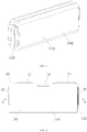
FIG. 8 is a structural schematic diagram showing a connection member according to the embodiment shown inFIG. 1 before a first connection plate is bent with respect to a guide plate. -
FIG. 9 is a structural schematic diagram showing a connection member shown inFIG. 8 after the first connection plate is bent with respect to the guide plate. -
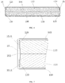
FIG. 10 is a structural schematic diagram showing a bottom view of a section-view of a rechargeable battery (in which a shell is not shown) according to one embodiment of the present disclosure. -
FIG. 11 is a structural schematic diagram showing an enlarged view of B portion inFIG. 10 . -
FIG. 12 is a structural schematic diagram showing a connection member of the rechargeable battery according to the embodiment shown inFIG. 10 before a first connection plate is bent with respect to the guide plate. -
FIG. 13 is a structural schematic diagram showing a connection member shown inFIG. 12 after the first connection plate is bent with respect to the guide plate. -
FIG. 14 is a structural schematic diagram of a connection member in a comparison embodiment; -
FIG. 15 is a structural schematic diagram showing a connection member after the first connection plate is bent towards an inside of the guide plate. - The technical solution in the embodiments of the present disclosure will be described in a clearly and fully understandable way in connection with the drawings of the embodiments of the disclosure. It is obvious that the described embodiments are just some but not all embodiments of the disclosure. The description on at least one exemplary embodiment below actually is merely illustrative, but definitely does not make any limit to the present disclosure or application and use thereof. Based on the embodiments of the disclosure, all other embodiment(s) obtained by those skilled in the art without any inventive work should be within the scope of protection of the disclosure.
- Unless specifically otherwise defined, relative arrangement, number expressions and values of parts and steps illustrated in those embodiments do not make any limit to the scope of the present disclosure. Meanwhile, it should be understood that in order to facilitate description, the size of each portion shown in the drawings is not drawn according to an actual proportional relationship. Technologies, methods and devices known by those skilled in the existing arts may be not discussed in detail, but in proper cases, the technologies, methods and devices should be regarded as one part of the granted specification. In all examples shown and discussed herein, any specific value should be explained to be merely exemplary, but not limitative. Therefore, other examples of the exemplary embodiments may have different values. It should be noted that similar reference signs and letters represent similar terms in the drawings below, and thus, once a certain term is defined in one drawing, it is not desired that the term shall be further discussed in the subsequent drawings.
- In the description of the present disclosure, it should be understood that words for defining parts, such as "first", "second" and the like, merely mean to facilitate distinguishing the corresponding parts, and unless otherwise statement, the above-mentioned words do not have special meanings, and are not limitative of the present disclosure.
- In the description of the present disclosure, it should be understood that the singular forms, "a," "an," and "the" are intended to include the plural forms as well, unless context clearly indicates otherwise.
- In the description of the present disclosure, it should be understood that directional or positional relationships shown by directional terms such as "front, rear, upper, lower, left and right", "transverse, vertical, perpendicular and horizontal", "top and bottom" and the like generally are directional or positional relationships shown as in the drawings, which only mean to facilitate description of the present disclosure and simplify the description, but in cases of no reverse explanation, do not indicate or imply that the devices or components must have specific directions, or be constructed or operated in the specific directions, and are not limitative of the scope of the present disclosure; and directional terms such as "inner and outer" mean inner and outer with respect to the contour of each component.
- In the description of this disclosure, the "longitudinal direction" means a longitudinal direction of a rechargeable battery, is also a longitudinal direction of a
cell 100, and corresponds to an X direction inFIG. 1 ; the "width direction" means a width direction of the rechargeable battery and corresponds to a Y direction inFIG. 1 , and the "width direction" is also a width direction of a connection member and a guide plate thereof; and the "height direction" means a direction perpendicular to the longitudinal direction and the width direction and corresponds to a Z direction inFIG. 1 , and the "height direction" is a height direction of the rechargeable battery and a cell and is also a height direction of the connection member and the guide plate thereof. - In existing technologies, there is a connection technique in which the first connection plate of the connection member is perpendicular to the longitudinal direction of the cell and meanwhile, the tabs are bent, and such technique is beneficial for improving the energy density of the rechargeable battery.
FIG. 14 shows a structural schematic diagram of an existing connection member. In the figure, theconnection member 135 includes aguide plate 1353, twofirst connection plates 1351 connected to both sides of theguide plate 1353 respectively in a width direction, and asecond connection plate 1352 connected to the upper end of the guide plate. Thefirst connection plates 1351 are arranged bendably with respect to theguide plate 1353. - In the process of implementing the present disclosure, a designer finds that in the rechargeable battery with the connection member as shown in
FIG. 14 , of which the first connection plates are perpendicular to the longitudinal direction of the cell, in order to implementing bending of the first connection plates, the connection member may have regions where resistances are locally increased at positions corresponding to the top ends of the guide plate and two first connection plates, so as to affect overcurrent capability of the connection member and affect rapid charging capability of the rechargeable battery. - In view of this, some embodiment of the present disclosure is to provide a connection member and a rechargeable battery, in order to improve overcurrent capability of the connection member and rapid charging capability of the rechargeable battery.
-
FIG. 1 to FIG. 13 show structures of a rechargeable battery and parts thereof according to each embodiment of the present disclosure. - As shown in
FIG. 1 to FIG. 13 , an embodiment of the present disclosure provides aconnection member 35 of a rechargeable battery, which is used for connecting acell 100 of the rechargeable battery and an exterior of the rechargeable battery. Theconnection member 35 includes aguide plate 353, afirst connection plate 351A, afirst connection plate 351B and asecond connection plate 352. Twofirst connection plates guide plate 353 in a width direction Y and are arranged bendably with respect to theguide plate 353. Thesecond connection plate 352 is connected to an upper end of theguide plate 353. Top ends of the twofirst connection plates cell 100 includes two groups of battery cells, as shown in the drawings. Also, each group can include one, two, three or more battery cells. - Due to a larger and larger demand on rapid charging of the rechargeable battery, the
connection member 35 needs to have a relatively large overcurrent area. Since the first connection plates have the bending demand, portions of theguide plate 353, which are connected with the first connection plates, are limited in width and sometimes may be only set to be relatively narrow, so that a necked port is formed on a current transfer path of theconnection member 35. If the tops of the first connection plates on both sides of theguide plate 353 are consistent in height, a size of the necked port is a width size of theguide plate 353 at the height positions of the tops of the two first connection plates. But in the connection member provided by the present disclosure, the top ends of the two first connection plates are at different heights, and then the size of the necked port is changed into a size of a connection line of points on both sides of the guide plate in the width direction at the corresponding heights of the two first connection plates, thereby enlarging the overcurrent area and benefiting for improving overcurrent capability of the connection member and rapid charging capability and safety performance of the rechargeable battery. - The rechargeable battery according to the embodiments of the present disclosure includes the above-mentioned
connection member 35, thereby having all the advantages of theconnection member 35. - The embodiments of the present disclosure will be illustrated in detail below in connection with
FIG. 1 to FIG. 13 . - In the embodiment shown in
FIG. 1 to FIG. 9 , as shown inFIG. 1 to FIG. 3 andFIG. 5 to FIG. 9 , theconnection member 35 includes theguide plate 353, twofirst connection plates second connection plate 352. - A
first connection plate tabs 120 of acell 100. Twofirst connection plates guide plate 353 in the width direction. Thesecond connection plate 352 is connected to the upper end of theguide plate 353. In this embodiment, the top end of thefirst connection plate 351A is higher than that of thefirst connection plate 351B. Bottom ends of the twofirst connection plates - In embodiments not shown in the drawings, the top end of the
first connection plate 351A may also be lower than that of thefirst connection plate 351B, or the bottom ends of the twofirst connection plates first connection plate 351A may also be higher or lower than that of thefirst connection plate 351B. - The
second connection plate 352 is used for forming an electrical connection between thecell 100 of the rechargeable battery and the exterior of the rechargeable battery. Thesecond connection plate 352 is connected to the upper end of theguide plate 353 in a height direction Z. After the rechargeable battery is assembled up, thesecond connection plate 352 is positioned above thecell 100, and is bent with respect to theguide plate 353 towards thecell 100. In this embodiment, thesecond connection plate 352 is connected with an electrode part arranged on atop cover 30 of the rechargeable battery. - In the embodiments not shown in the drawings, the second connection plate may also be used as the electrode part of the rechargeable battery without specially providing the electrode part.
- In this embodiment, the
second connection plate 352 is provided with awelding connection portion 3521 for connecting to the electrode part. In order to accurately position a welding position where thesecond connection plate 352 is welded to the electrode part, a first positioning hole may be formed on thewelding connection portion 3521. A second positioning hole may also be formed at other position at thesecond connection plate 352, which do not belong to thewelding connection portion 3521. - In
FIG. 9 , H represents a height difference between the top end of thefirst connection plate 351A and the top end of thefirst connection plate 351B. Preferably, a ratio of the height difference H between the top end of thefirst connection plate 351A and the top end of thefirst connection plate 351B to a plate height of thefirst connection plate 351B which has a smaller plate height of the twofirst connection plates - In some preferred embodiments, the
guide plate 353 includes amain plate 3531 and epitaxial plates, twofirst connection plates main plate 3531, the epitaxial plates are spaced above the corresponding first connection plates respectively and extend towards an outside of themain plate 3531 along the width direction. - The arrangement of the epitaxial plates is more beneficial for enlarging the overcurrent area and reducing a resistance of the
guide plate 353 and beneficial for improving rapid charging capability and safety performance of the rechargeable battery. - As shown in
FIG. 1 to FIG. 3 andFIG. 5 to FIG. 9 , in this embodiment, theguide plate 353 includes anepitaxial plate 3533 corresponding to thefirst connection plate 351A, and anepitaxial plate 3534 corresponding to thefirst connection plate 351B. - In a preferred embodiment, a ratio of a gap between the first connection plate, which has a higher top end of the two first connection plates, and the corresponding epitaxial plate to the plate height of the first connection plate which has a smaller plate height of the two first connection plates is 0.006 to 0.15. Such arrangement is beneficial for smoothly bending the first connection plates. Accordingly, in this embodiment, the ratio is a ratio of the gap between the
first connection plate 351A and theepitaxial plate 3533 to the plate height of thefirst connection plate 351B. - In a preferred embodiment, a ratio of the gap between the first connection plate, which has a lower top end of the two first connection plates, and the corresponding epitaxial plate to the plate height of the first connection plate which has a smaller plate height of the two first connection plates is 0.006 to 0.15. Such arrangement is beneficial for smoothly bending the first connection plates. Accordingly, in this embodiment, the ratio is a ratio of the gap between the
first connection plate 351B and theepitaxial plate 3534 to the plate height of thefirst connection plate 351B. - In this embodiment, the gap between the
first connection plate 351A and theepitaxial plate 3533 may be equal to or unequal to the gap between thefirst connection plate 351B and theepitaxial plate 3534. - In addition, in a preferred embodiment, the
guide plate 353 and thesecond connection plate 352 are integrally formed by bending a sheet, and at least oneconvex mark 35D is formed at the bent position between theguide plate 353 and thesecond connection plate 352. - As shown in
FIG. 8 andFIG. 9 , theguide plate 353 and thesecond connection plate 352 of theconnection member 35 are integrally formed by bending, and twoconvex marks 35D are formed at the bent position between theguide plate 353 and thesecond connection plate 352. In this embodiment, the twoconvex marks 35D are uniformly spaced along the bent position between theguide plate 353 and thesecond connection plate 352. - The
convex marks 35D can facilitate theguide plate 353 and thesecond connection plate 352 to keep at relative positions when the first connection plates are bent, so that when the rechargeable battery is assembled, mutual positions of each part connected with theconnection member 35, such as thecell 100, thetop cover 30, ashell 20 and the like, are accurate and uniform, which is beneficial for smoothly completing the assembling work and is also beneficial for improving quality of the rechargeable battery. Moreover, when the rechargeable battery is impacted or vibrated, a deformation amount of theguide plate 353 with respect to thesecond connection plate 352 can be reduced so as to benefit protection to thetabs 120. - As shown in
FIG. 1 to FIG. 9 , in this embodiment, thefirst connection plate 351A and thefirst connection plate 351B are arranged bendably and towards an outside of theguide plate 353 respectively. - According to the embodiment of the present disclosure, the rechargeable battery includes the
cell 100 and the above-mentionedconnection member 35, and the first connection plates of theconnection member 35 are connected with thetabs 120 of thecell 100. - In the embodiment shown in
FIG. 1 to FIG. 9 , the rechargeable battery includes theshell 20, thetop cover 30, thecell 100 and theconnection member 35. As shown inFIG. 1 , in this embodiment, theshell 20 is a metal shell, and in order to prevent electricity leakage of theshell 20, the rechargeable battery may further include aninsulation layer 40. Theinsulation layer 40 is arranged between theconnection member 35, and theshell 20. - The
shell 20 and thetop cover 30 form a mounting space, and thecell 100 and the portions of theguide plate 353 and thefirst connection plates connection member 35 below thetop cover 30 are positioned in the mounting space. - The
second connection plate 352 of theconnection member 35 is connected with the electrode part on thetop cover 30. Specifically, thewelding connection portion 3521 is arranged on thesecond connection plate 352, and thesecond connection plate 352 is welded and connected with the electrode part by thewelding connection portion 3521. - The electrode part on the
top cover 30 includes apositive electrode part 31 for connecting to a positive pole of thecell 100 and anegative electrode part 34 for connecting to a negative pole of thecell 100. An explosion-proof valve 32 is also arranged on thetop cover 30. Other structures, such as a liquid filling hole and the like, can also be arranged on thetop cover 30. - The
connection member 35 of the rechargeable battery generally may be firstly fixedly connected with thetop cover 30 and the electrode part thereon, and then be connected with thecell 100. When theconnection member 35 is connected with thecell 100, after the position of theguide plate 353 with respect to amain body 110 of thecell 100 is determined, thefirst connection plates tabs 120 with a certain angle with respect to the end face of themain body 110 of thecell 100, then thefirst connection plates tabs 120 are simultaneously bent with respect to a longitudinal direction X of themain body 110 of thecell 100. For example, in this embodiment, thefirst connection plates main body 110 of thecell 100. After theconnection member 35 and thecell 100 are assembled, theconnection member 35 and thecell 100 are placed into theshell 20 together. After theconnection member 35 and thecell 100 are placed well, thetop cover 30 just covers an opening of theshell 20, and then thetop cover 30 and theshell 20 are sealed. - As shown in
FIG. 1 ,FIG.2 andFIG.4 toFIG.7 , in this embodiment, thecell 100 includes themain body 110 of thecell 100 and thetabs 120 extending away from themain body 110. - The
cell 100 is a prismatic cell formed by winding after overlaying a positive plate, an isolation film and a negative plate. A width direction of the positive plate, the isolation film and the negative plate form the longitudinal direction X of thecell 100. - The positive plate and the negative plate respectively include a substrate and an active material coated on the substrate. A coating region is formed in a region on the substrate, where the active material is coated. The isolation film is used for isolating the positive plate from the negative plate so as to prevent the short circuit inside the rechargeable battery. The substrate of the positive plate may be a first metal foil, e.g., an aluminium foil; and the substrate of the negative plate may be a second metal foil, e.g., a copper foil.
- The
cell 100 includes a positive tab and a negative tab. The positive tab is formed by a portion at the edge of one side of the first metal foil, which is uncoated with the active material. The negative tab is formed by a portion at the edge of one side of the second metal foil, which is uncoated with the active material. In this embodiment, the positive tab and the negative tab are positioned at two ends of thecell 100 respectively in the longitudinal direction X, and protrude from the corresponding end portions of the isolation film respectively. - As shown in
FIG. 4 , in thecell 100 in this embodiment, thetabs 120 extend from one side of themain body 110 in the width direction Y. In this embodiment, thetabs 120 are arranged at one side with respect to center plane of themain body 110 in the width direction Y, so that in the premise of ensuring that the tabs have a sufficient overcurrent area, a thickness of thetabs 120 is effectively reduced. By the arrangement, after thefirst connection plates guide plate 353, a size occupied by thetabs 120 in the longitudinal direction X of thecell 100 is thinned, so that thefirst connection plates main body 110, and the overall size of theconnection member 35 and thecell 100 in the longitudinal direction X is reduced, thereby improving the energy density of the rechargeable battery. In addition, thetabs 120 includes multiple layers, and thus, thickness reduction of thetabs 120 is further beneficial for reducing a dislocation phenomenon among the multiple layers of thetabs 120, which is caused by bending. - In this embodiment, the
tabs 120 include the positive tab and the negative tab which are respectively arranged at two ends of themain body 110 in the longitudinal direction X. The positive tab and the negative tab may be arranged on the same side of themain body 110 in the width direction Y. - In embodiments not shown in the drawings, the positive tab and the negative tab may also be arranged on different sides in the width direction Y. According to a simulation result, compared to the arrangement that the positive tab and the negative tab are arranged on the same side of the
main body 110 in the width direction Y, such arrangement can make current density more uniform. - As shown in
FIG. 4 , thetabs 120 are positioned at the middle portion of themain body 110 in the height direction Z. In the height direction Z of thecell 100, two vacancies are respectively formed at upper and lower portions of thetabs 120, which make thetabs 120 easier to bend. - The
connection member 35 is positioned at the end portion of thecell 100 in the longitudinal direction X. In this embodiment, twoconnection members 35 are respectively arranged at two ends of thecell 100 in the longitudinal direction X. Oneconnection member 35 is connected with the positive tab of thecell 100, and the other connection member is connected with the negative tab of thecell 100. Theconnection member 35 connected with the positive tab of thecell 100 is connected with thepositive electrode part 31 on thetop cover 30, and theconnection member 35 connected with the negative tab of thecell 100 is connected with thenegative electrode part 34 on thetop cover 30, so that due to theconnection members 35, connections between thetabs 120 and the corresponding electrode parts can be achieved. - In this embodiment, the
first connection plates guide plate 353 in the width direction, and in parallel to the end face of themain body 110, i.e., perpendicular to the longitudinal direction X of thecell 100. - When the
connection member 35 is assembled with the cell, after the position of theguide plate 353 with respect to thecell 100 is determined, thefirst connection plates tabs 120 in a state of being in parallel to the longitudinal direction X of thecell 100, and then thefirst connection plates guide plate 353 so as to complete assembling of theconnection member 35 and thecell 100. - In some embodiments not shown in the drawings, after the position of the
guide plate 353 with respect to thecell 100 is determined, thefirst connection plates tabs 120 in a state of being deviated from the longitudinal direction X of thecell 100 by a certain angle, and then thefirst connection plates guide plate 353 so as to complete assembling of theconnection member 35 and thecell 100. - In each above-mentioned assembling manner, a large operation space exists in the process of fixing the
tabs 120 to thefirst connection plates tabs 120 and thefirst connection plates tabs 120 and the first connection plates. - In this embodiment, the rechargeable battery includes two
cells 100 connected in parallel, and thetabs 120 of the twocells 100 having same polarity are respectively connected with twofirst connection plates cells 100 are symmetrically arranged. - In this embodiment,
tabs 120 of each of the twocells 100 are positioned on one side close to theother cell 100. Namely, a portion of thetabs 120, which is connected with themain body 110, is positioned at the inner side of the rechargeable battery in the width direction Y. - The
first connection plates main body 110 so as to effectively reduce a space occupied by theconnection member 35 at the end portion of the rechargeable battery in the longitudinal direction X, and thetabs 120 extend out from one side of themain body 110 in the width direction Y so as to effectively reduce the thickness of thetabs 120 and further reduce a space occupied at the joint of theconnection member 35 and thetabs 120, thereby effectively improving a space utilization rate of the rechargeable battery and the energy density of the rechargeable battery. Meanwhile, an activity space of thetabs 120 is reduced, and the probability that thetabs 120 are cracked by pulling and the probability that thetabs 120 are inserted into themain body 110 after being squeezed are reduced, so that the resultant risk of short circuit inside the battery is reduced, and a service life and safety performance of thecell 100 are improved. - In addition, as shown in
FIG. 6 and FIG. 7 , in a preferred embodiment, theguide plate 353 at least partially protrudes towards thecell 100 with respect to thefirst connection plates tabs 120 of thecell 100. Portions of thetabs 120, which are connected with themain body 110, are positioned between theguide plate 353 and themain body 110. - The
guide plate 353 at least partially protrudes towards thecell 100 with respect to thefirst connection plates tabs 120 of thecell 100, and thus, when the rechargeable battery is vibrated or impacted, a portion of theguide plate 353, which protrudes towards thecell 100 with respect to thefirst connection plates cell 100 to enable theconnection member 35 to bear a stress, so that a pull crack phenomenon of thetabs 120, which is caused by vibration or impact, can be effectively relieved, and meanwhile, the activity space of thetabs 120 is reduced, and the probability that thetabs 120 are inserted into themain body 110 after being squeezed is reduced, so that the resultant risk of short circuit inside the battery is reduced. Due to reduction of both the probability that thetabs 120 are cracked by pulling and the probability that the tabs are inserted into themain body 110, the service life and safety performance of thecell 100 can be improved. - In this embodiment, the connection between the
first connection plates connection member 35 and thetabs 120 of thecells 100 can be achieved by ultrasonic welding or laser welding or resistance welding, and meanwhile, the fixed connection with a certain strength is achieved. After welding connection, by bending thefirst connection plates connection member 35 outwards, an internal space occupied by theconnection member 35 and thecell 100 in the longitudinal direction X of thecell 100 is reduced. - In some embodiments, the
tabs 120 of each of the twocells 100 can be positioned on one side away from theother cell 100. - As shown in
FIG. 10 to FIG. 13 , in this embodiment, thetabs 120 of each of the twocells 100 are positioned on one side away from theother cell 100. Namely, a position of thetabs 120, which is connected with themain body 110, is positioned at the outer side of the rechargeable battery in the width direction Y. - In this embodiment, the
guide plate 353 includes themain plate 3531 and aflanging 3532, theflanging 3532 is positioned at the side edge of themain plate 3531 in a width direction and extends towards a direction away from thecell 100, and thefirst connection plates main plate 3531 through theflanging 3532. - In this embodiment, the
flanging 3532 is perpendicular to themain plate 3531. In other embodiments not shown in the drawings, theflanging 3532 may also be inclined towards the inner side of themain plate 3531, or theflanging 3532 may be inclined towards the outer side of themain plate 3531. - The
first connection plates main plate 3531 after being bent with respect to theguide plate 353. In this case, both thefirst connection plates main plate 3531 are perpendicular to the longitudinal direction X of thecell 100. - In embodiments not shown in the drawings, the
first connection plates main plate 3531 may also have a certain angle, and for example, the outer ends of thefirst connection plates main body 110 than the inner ends of thefirst connection plates - Preferably, in this embodiment, the
whole guide plate 353 is in contact with a surface at one end of themain body 110. As shown inFIGs. 10 to 11 , themain plate 3531 of theconnection member 35 is in contact with a surface at one end of themain body 110, i.e., is in contact with the end face of the isolation film at the end portion of thecell 100 in the longitudinal direction X. As such, thetabs 120 nearly do not bear fixing and positioning functions of thecell 100 in the longitudinal direction X, so that thetabs 120 can be more effectively protected from being damaged. After being in contact with the end face of the isolation film of thecell 100, themain plate 3531 of theconnection member 35 compresses thecell 100 so as to take an effect of supporting, fixing and positioning thecell 100 along the longitudinal direction X of thecell 100 and prevent shaking of thecell 100 inside theshell 20 after the rechargeable battery is assembled. - As shown in
FIGs. 12 to 13 , in this embodiment, at least oneindentation 35A can be formed at a bent position between thefirst connection plate 351A and theguide plate 353, as well as between thefirst connection plate 351B and theguide plate 353. - By forming the
indentations 35A, a weak link is formed between the first connection plates and theguide plate 353 at the positions of theindentations 35A, so that when the first connection plates are bent with respect to theguide plate 353, the bent positions are more accurate, which is beneficial to size accuracy of theconnection member 35 after bending and is also beneficial for smoothly completing assembling of thecell 100, theconnection member 35 and theshell 20 of the rechargeable battery. Moreover, due to theindentations 35A, the first connection plates are more labor-saving to bend, so that the damage to thecell 100 and thetabs 120 thereof, which is possibly generated due to bending, is reduced. - As shown in
FIG. 12 to FIG. 13 , in this embodiment, a crack-arrest notch is formed at the end portion of the joint between thefirst connection plate 351A (or thefirst connection plate 351B) and theguide plate 353. Afirst notch 35B is formed at the root portion of the upper end of the joint between theguide plate 353 and the first connection plate, and asecond notch 35C is formed at the root portion of the lower end of the joint between theguide plate 353 and the first connection plate (351A or 351B). - By forming the crack-arrest notches, it is not easy for the
connection member 35 to be damaged at the end portion of the joint during the bending process, and the cracking problem at the end portion of theconnection member 35 in the bending process is effectively solved. - In addition, in some embodiments not shown in the drawings, thicknesses of the
first connection plate 351A and thefirst connection plate 351B may be less than that of theguide plate 353. - Compared to a connection member of which a first connection plate has the same thickness with the guide plate, the
connection member 35 occupies a further reduced rechargeable battery space after theconnection member 35 is bent, so that the energy density of the rechargeable battery can be further improved. Meanwhile, due to reduction of the thickness of the first connection plate, welding assembling quality of the first connection plates and the tabs of the rechargeable battery can be effectively improved. The thickness of the guide plate is still kept relatively large, which helps to reduce a resistance of the guide plate, thereby enabling an internal resistance of the rechargeable battery to meet demands and benefiting for ensuring electrical performance of the rechargeable battery. In addition, the thickness of the first connection plate is less than the thickness of the guide plate, which is also beneficial for bending the first connection plate, so as to benefit for ensuring relative positions of the connection member and the cell after bending, thereby benefiting for assembling and also benefiting for reducing damage to the main body of the cell or the tabs in the bending process. - Parts which are not illustrated in the embodiment corresponding to
FIGs. 10 to 13 can be referred to related description in the embodiment corresponding toFIGs. 1 to 9 . - The above embodiments should not constitute limitation to the present disclosure, for example:
In some embodiments not shown in the drawings, the first connection plate may also be flush with the plate face of the guide plate after being bent outwards. - In an embodiment shown in
FIG. 15 , thefirst connection plate 351A and thefirst connection plate 351B are bent towards an inside of theguide plate 353. Preferably, the two first connection plates are not overlapped in the width direction of the guide plate. - In some embodiments not shown in the drawings, the rechargeable battery may further include a spacer fixedly connected with the first connection plates and the tabs, and the tabs are positioned between the first connection plate and the spacer so as to benefit for protecting the tab and prolonging the service life of the rechargeable battery. The spacer can be electrically conductive.
- In some embodiments not shown in the drawings, the first connection plate may also be connected with one group of
cells 100. For example, each first connection plate is connected with one group of cells, the tabs are arranged on one side of the main bodies of the cells in the width direction Y, each of the two groups of cells may include two cells, and the tabs of each cell in two cells in one group is positioned on one side close to the other cell. - Each above embodiment of the present disclosure, as long as technical characteristics have no conflict, can refer to or combine related technical contents of other embodiments.
- Finally, it should be illustrated that: the above embodiments merely are used for illustrating the technical solution of the present disclosure, but not limitative of the present disclosure; and although the present disclosure is illustrated in detail with reference to the preferred embodiments, those skilled in the art should understand that: modifications can still be made to the specific embodiments of the present disclosure or equivalent replacements can still be made to part of technical characteristics; all the modifications and the equivalent replacements shall fall within the scope of the technical solution of the present disclosure.
Claims (15)
- A connection member (35) for a rechargeable battery, comprising:a guide plate (353), two first connection plates (351A, 351B) and a second connection plate (352);wherein the two first connection plates (351A, 351B) respectively connects to two sides of the guide plate (353) in a width direction and are arranged bendably with respect to the guide plate (353), the second connection plate (352) connects to an upper end of the guide plate (353),wherein, top ends of the two first connection plates (351A, 351B) are at different heights.
- The connection member (35) according to claim 1, wherein, a ratio of a height difference (H) between the top ends of the two first connection plates (351A, 351B) to a plate height of the first connection plate (351B) which has a smaller plate height of the two first connection plates (351A, 351B) is 0.01 to 0.25.
- The connection member (35) according to claim 1 or 2, wherein, the guide plate (353) comprises a main plate (3531) and an epitaxial plate (3533, 3534), the two first connection plates (351A, 351B) are connected to the main plate (3531), the epitaxial plate (3533, 3534) is spaced above one of the two first connection plates (351A, 351B) and extends towards an outside of the main plate (3531) along the width direction.
- The connection member (35) according to claim 3, wherein, the guide plate (353) comprises two epitaxial plates (3533, 3534), each of the two epitaxial plates (3533, 3534) corresponds to one of the two first connection plates (351A, 351B).
- The connection member (35) according to claim 4, wherein,
a ratio of a gap between one of the two first connection plates (351A) which has a higher top end of the two first connection plates (351A, 351B) and the corresponding epitaxial plate (3533) to a plate height of one of the two first connection plates (351B) which has a smaller plate height of the two first connection plates (351A, 351B) is 0.006 to 0.15; and/or,
a ratio of a gap between one of the two first connection plates (351B) which has a lower top end of the two first connection plates (351A, 351B) and the corresponding epitaxial plate (3533) to a plate height of one of the two first connection plates (351B) which has a smaller plate height of the two first connection plates (351A, 351B) is 0.006 to 0.15. - The connection plate (35) according to any one of claims 1 to 5, wherein, the second connection plate (352) and the guide plate (353) are integrally formed by bending, and at least one convex mark (35D) is formed at a bent position between the guide plate (353) and the second connection plate (352).
- The connection member (35) according to any one of claims 1 to 6, wherein, at least one indentation (35A) is respectively formed at a bent position between one of the two first connection plates (351A, 351B) and the guide plate (353).
- The connection member (35) according to any one of claims 1 to 7, wherein, a crack-arrest notch (35B, 35C) is formed at an end portion of the joint between one of the two first connection plates (351A, 351B) and the guide plate 353.
- The connection member (35) according to any one of claims 1 to 8, wherein, a thickness of each of the two first connection plates (351A, 351B) is less than that of the guide plate (353).
- A rechargeable battery, comprising two or more cells (100) and the connection member (35) according to any one of claims 1 to 10, each of the two first connection plates (351A, 351B) being connected with tabs (120) of the cells (100).
- The rechargeable battery according to claim 10, wherein, the two first connection plates (351A, 351B) are bent towards an outside of the guide plate (353) along the width direction, respectively.
- The rechargeable battery according to claim 10 or 11, wherein, the guide plate (353) at least partially protrudes towards a main body (110) of the cells (100) with respect to the first connection plates (351A, 351B) to form a protrusion, and the protrusion is pressed against the tabs (120) of the cells (100) or the protrusion is pressed against the main body (110) of the cells (100).
- The rechargeable battery according to claim 12, wherein, the tabs (120) extend from one side of the main body (110) of the cell (100) in a width direction (Y).
- The rechargeable battery according to any one of claims 10 to 13, wherein, the guide plate (353) is in contact with a surface at one end of the main body (110) of the cells (100).
- The rechargeable battery according to any one of claims 10 to 14, wherein, the two first connection plates (351A, 351B) are bent towards an inside of the guide plate (353) along the width direction, respectively.
Applications Claiming Priority (1)
| Application Number | Priority Date | Filing Date | Title |
|---|---|---|---|
| CN201810039471.1A CN108198989B (en) | 2018-01-16 | 2018-01-16 | Connecting member and rechargeable battery |
Publications (2)
| Publication Number | Publication Date |
|---|---|
| EP3512006A1 true EP3512006A1 (en) | 2019-07-17 |
| EP3512006B1 EP3512006B1 (en) | 2020-10-28 |
Family
ID=62589195
Family Applications (1)
| Application Number | Title | Priority Date | Filing Date |
|---|---|---|---|
| EP18248061.6A Active EP3512006B1 (en) | 2018-01-16 | 2018-12-27 | Connection member and rechargeable battery |
Country Status (4)
| Country | Link |
|---|---|
| US (1) | US10910622B2 (en) |
| EP (1) | EP3512006B1 (en) |
| CN (1) | CN108198989B (en) |
| HU (1) | HUE051796T2 (en) |
Cited By (1)
| Publication number | Priority date | Publication date | Assignee | Title |
|---|---|---|---|---|
| EP3872892A4 (en) * | 2018-12-29 | 2021-12-29 | Contemporary Amperex Technology Co., Limited | Current collector and secondary battery |
Families Citing this family (13)
| Publication number | Priority date | Publication date | Assignee | Title |
|---|---|---|---|---|
| JP7013891B2 (en) * | 2018-01-30 | 2022-02-01 | トヨタ自動車株式会社 | Power storage device |
| CN111384350B (en) * | 2018-12-29 | 2024-10-15 | 宁德时代新能源科技股份有限公司 | Secondary battery and battery module |
| CN111384351B (en) | 2018-12-29 | 2024-10-01 | 宁德时代新能源科技股份有限公司 | Secondary battery and battery module |
| CN111384332B (en) | 2018-12-29 | 2024-10-01 | 宁德时代新能源科技股份有限公司 | Battery modules and battery packs |
| CN111384352B (en) * | 2018-12-29 | 2024-10-15 | 宁德时代新能源科技股份有限公司 | Secondary battery and battery module |
| CN111384464B (en) * | 2018-12-29 | 2024-09-10 | 宁德时代新能源科技股份有限公司 | Battery modules and battery packs |
| CN111384353B (en) * | 2018-12-29 | 2024-10-15 | 宁德时代新能源科技股份有限公司 | Secondary battery and battery module |
| CN111463367B (en) * | 2019-01-22 | 2024-09-06 | 宁德时代新能源科技股份有限公司 | Secondary battery and battery module |
| CN111864172B (en) * | 2019-04-25 | 2025-01-17 | 宁德时代新能源科技股份有限公司 | Battery unit and battery module |
| JP7449468B2 (en) * | 2020-04-01 | 2024-03-14 | トヨタ自動車株式会社 | Current collector terminal |
| KR102947705B1 (en) * | 2021-11-19 | 2026-04-02 | 컨템포러리 엠퍼렉스 테크놀로지 (홍콩) 리미티드 | Battery cell, battery, electrical device and method and equipment for manufacturing battery cell |
| KR20240057717A (en) * | 2022-10-25 | 2024-05-03 | 삼성에스디아이 주식회사 | Secondary battery |
| CN220291021U (en) * | 2023-06-16 | 2024-01-02 | 湖北亿纬动力有限公司 | Battery core |
Citations (3)
| Publication number | Priority date | Publication date | Assignee | Title |
|---|---|---|---|---|
| EP2846378A1 (en) * | 2013-09-10 | 2015-03-11 | Samsung SDI Co., Ltd. | Rechargeable battery having a fuse |
| EP3133673A1 (en) * | 2014-04-18 | 2017-02-22 | Hitachi Automotive Systems, Ltd. | Rectangular secondary battery |
| US20170358790A1 (en) * | 2014-09-11 | 2017-12-14 | Gs Yuasa International Ltd. | Energy storage device |
Family Cites Families (14)
| Publication number | Priority date | Publication date | Assignee | Title |
|---|---|---|---|---|
| US8268478B2 (en) * | 2009-08-17 | 2012-09-18 | Sb Limotive Co., Ltd. | Rechargeable battery having anti-vibration member |
| US8232000B2 (en) * | 2010-01-12 | 2012-07-31 | Sb Limotive Co., Ltd. | Rechargeable battery with terminal junction and prong |
| US8628878B2 (en) * | 2010-04-12 | 2014-01-14 | Samsung Sdi Co., Ltd. | Hooked retainer for electrode body in rechargeable battery |
| KR101147174B1 (en) * | 2010-11-25 | 2012-05-25 | 에스비리모티브 주식회사 | Secondary battery |
| KR101222415B1 (en) * | 2011-01-13 | 2013-01-14 | 로베르트 보쉬 게엠베하 | Secondary battery |
| JP5663415B2 (en) * | 2011-06-24 | 2015-02-04 | 日立オートモティブシステムズ株式会社 | Secondary battery |
| US8940420B2 (en) * | 2011-09-29 | 2015-01-27 | Samsung Sdi Co., Ltd. | Rechargeable battery |
| US9083039B2 (en) * | 2012-03-28 | 2015-07-14 | Samsung Sdi Co., Ltd. | Rechargeable battery |
| KR20140137180A (en) * | 2013-05-22 | 2014-12-02 | 삼성에스디아이 주식회사 | Rechargeable battery |
| KR20150089311A (en) * | 2014-01-27 | 2015-08-05 | 삼성에스디아이 주식회사 | Secondary Battery |
| KR102221802B1 (en) * | 2014-02-07 | 2021-03-02 | 삼성에스디아이 주식회사 | Secondary battery |
| EP3451415B1 (en) * | 2017-08-31 | 2020-03-25 | Samsung SDI Co., Ltd. | Secondary battery |
| KR102371196B1 (en) * | 2017-08-31 | 2022-03-07 | 삼성에스디아이 주식회사 | Secondary Battery |
| KR102425218B1 (en) * | 2017-08-31 | 2022-07-26 | 삼성에스디아이 주식회사 | Secondary Battery |
-
2018
- 2018-01-16 CN CN201810039471.1A patent/CN108198989B/en active Active
- 2018-12-27 EP EP18248061.6A patent/EP3512006B1/en active Active
- 2018-12-27 HU HUE18248061A patent/HUE051796T2/en unknown
- 2018-12-28 US US16/234,955 patent/US10910622B2/en active Active
Patent Citations (3)
| Publication number | Priority date | Publication date | Assignee | Title |
|---|---|---|---|---|
| EP2846378A1 (en) * | 2013-09-10 | 2015-03-11 | Samsung SDI Co., Ltd. | Rechargeable battery having a fuse |
| EP3133673A1 (en) * | 2014-04-18 | 2017-02-22 | Hitachi Automotive Systems, Ltd. | Rectangular secondary battery |
| US20170358790A1 (en) * | 2014-09-11 | 2017-12-14 | Gs Yuasa International Ltd. | Energy storage device |
Cited By (1)
| Publication number | Priority date | Publication date | Assignee | Title |
|---|---|---|---|---|
| EP3872892A4 (en) * | 2018-12-29 | 2021-12-29 | Contemporary Amperex Technology Co., Limited | Current collector and secondary battery |
Also Published As
| Publication number | Publication date |
|---|---|
| CN108198989B (en) | 2021-01-12 |
| EP3512006B1 (en) | 2020-10-28 |
| US20190221813A1 (en) | 2019-07-18 |
| CN108198989A (en) | 2018-06-22 |
| US10910622B2 (en) | 2021-02-02 |
| HUE051796T2 (en) | 2021-03-29 |
Similar Documents
| Publication | Publication Date | Title |
|---|---|---|
| US10910622B2 (en) | Connection member and rechargeable battery | |
| US11742526B2 (en) | Rechargeable battery | |
| KR102944814B1 (en) | Secondary battery | |
| KR102804305B1 (en) | Battery cell and its manufacturing method and manufacturing system, battery and electric device | |
| US20230121494A1 (en) | Electrode assembly for battery and battery | |
| KR20220149773A (en) | Battery cell, manufacturing method thereof, manufacturing system, battery and power consumption device | |
| EP4068490B1 (en) | Battery cell, battery, electric device, and manufacturing method and device for battery cell | |
| CN108199072B (en) | Rechargeable Battery | |
| KR20050121914A (en) | Secondary battery and electrodes assembly | |
| EP4564583A1 (en) | Battery cell and assembly method therefor, battery, electrical device, and assembly device | |
| KR20200091687A (en) | The Electrode Assembly And The Secondary Battery | |
| KR102797474B1 (en) | The Case For Secondary Battery And The Pouch Type Secondary Battery | |
| KR102337491B1 (en) | Secondary battery | |
| EP3139425A1 (en) | Method for manufacturing rechargeable battery and rechargeable battery manufactured using the same | |
| US12315960B2 (en) | Current collecting member and manufacturing method thereof, secondary battery and manufacturing method thereof, battery module, and apparatus | |
| US20250096437A1 (en) | Battery cell, battery, and electric device | |
| EP4375004A1 (en) | Secondary battery and methof of manufacturing said secondary batterie | |
| KR20210076770A (en) | The Case For Secondary Battery And The Pouch Type Secondary Battery | |
| EP4366070A2 (en) | Secondary battery with welded electrode assembly | |
| CN208045591U (en) | Connecting elements and rechargeable battery | |
| US20140023913A1 (en) | Prismatic secondary battery | |
| KR102172843B1 (en) | Secondary Battery | |
| US20260031446A1 (en) | Battery cell, battery, and electric apparatus | |
| KR20210098756A (en) | The Case For Secondary Battery And The Secondary Battery | |
| KR102807074B1 (en) | Battery and method for manufacturing same |
Legal Events
| Date | Code | Title | Description |
|---|---|---|---|
| PUAI | Public reference made under article 153(3) epc to a published international application that has entered the european phase |
Free format text: ORIGINAL CODE: 0009012 |
|
| STAA | Information on the status of an ep patent application or granted ep patent |
Free format text: STATUS: REQUEST FOR EXAMINATION WAS MADE |
|
| 17P | Request for examination filed |
Effective date: 20190605 |
|
| AK | Designated contracting states |
Kind code of ref document: A1 Designated state(s): AL AT BE BG CH CY CZ DE DK EE ES FI FR GB GR HR HU IE IS IT LI LT LU LV MC MK MT NL NO PL PT RO RS SE SI SK SM TR |
|
| AX | Request for extension of the european patent |
Extension state: BA ME |
|
| STAA | Information on the status of an ep patent application or granted ep patent |
Free format text: STATUS: EXAMINATION IS IN PROGRESS |
|
| 17Q | First examination report despatched |
Effective date: 20190925 |
|
| GRAP | Despatch of communication of intention to grant a patent |
Free format text: ORIGINAL CODE: EPIDOSNIGR1 |
|
| STAA | Information on the status of an ep patent application or granted ep patent |
Free format text: STATUS: GRANT OF PATENT IS INTENDED |
|
| INTG | Intention to grant announced |
Effective date: 20200507 |
|
| GRAJ | Information related to disapproval of communication of intention to grant by the applicant or resumption of examination proceedings by the epo deleted |
Free format text: ORIGINAL CODE: EPIDOSDIGR1 |
|
| STAA | Information on the status of an ep patent application or granted ep patent |
Free format text: STATUS: EXAMINATION IS IN PROGRESS |
|
| INTC | Intention to grant announced (deleted) | ||
| GRAS | Grant fee paid |
Free format text: ORIGINAL CODE: EPIDOSNIGR3 |
|
| STAA | Information on the status of an ep patent application or granted ep patent |
Free format text: STATUS: GRANT OF PATENT IS INTENDED |
|
| GRAP | Despatch of communication of intention to grant a patent |
Free format text: ORIGINAL CODE: EPIDOSNIGR1 |
|
| GRAA | (expected) grant |
Free format text: ORIGINAL CODE: 0009210 |
|
| STAA | Information on the status of an ep patent application or granted ep patent |
Free format text: STATUS: THE PATENT HAS BEEN GRANTED |
|
| INTG | Intention to grant announced |
Effective date: 20200915 |
|
| AK | Designated contracting states |
Kind code of ref document: B1 Designated state(s): AL AT BE BG CH CY CZ DE DK EE ES FI FR GB GR HR HU IE IS IT LI LT LU LV MC MK MT NL NO PL PT RO RS SE SI SK SM TR |
|
| REG | Reference to a national code |
Ref country code: GB Ref legal event code: FG4D |
|
| REG | Reference to a national code |
Ref country code: CH Ref legal event code: EP |
|
| REG | Reference to a national code |
Ref country code: AT Ref legal event code: REF Ref document number: 1329134 Country of ref document: AT Kind code of ref document: T Effective date: 20201115 |
|
| REG | Reference to a national code |
Ref country code: DE Ref legal event code: R096 Ref document number: 602018009147 Country of ref document: DE |
|
| REG | Reference to a national code |
Ref country code: IE Ref legal event code: FG4D |
|
| REG | Reference to a national code |
Ref country code: DE Ref legal event code: R079 Ref document number: 602018009147 Country of ref document: DE Free format text: PREVIOUS MAIN CLASS: H01M0002260000 Ipc: H01M0050531000 |
|
| REG | Reference to a national code |
Ref country code: NL Ref legal event code: FP |
|
| REG | Reference to a national code |
Ref country code: AT Ref legal event code: MK05 Ref document number: 1329134 Country of ref document: AT Kind code of ref document: T Effective date: 20201028 |
|
| REG | Reference to a national code |
Ref country code: HU Ref legal event code: AG4A Ref document number: E051796 Country of ref document: HU |
|
| PG25 | Lapsed in a contracting state [announced via postgrant information from national office to epo] |
Ref country code: RS Free format text: LAPSE BECAUSE OF FAILURE TO SUBMIT A TRANSLATION OF THE DESCRIPTION OR TO PAY THE FEE WITHIN THE PRESCRIBED TIME-LIMIT Effective date: 20201028 Ref country code: PT Free format text: LAPSE BECAUSE OF FAILURE TO SUBMIT A TRANSLATION OF THE DESCRIPTION OR TO PAY THE FEE WITHIN THE PRESCRIBED TIME-LIMIT Effective date: 20210301 Ref country code: FI Free format text: LAPSE BECAUSE OF FAILURE TO SUBMIT A TRANSLATION OF THE DESCRIPTION OR TO PAY THE FEE WITHIN THE PRESCRIBED TIME-LIMIT Effective date: 20201028 Ref country code: NO Free format text: LAPSE BECAUSE OF FAILURE TO SUBMIT A TRANSLATION OF THE DESCRIPTION OR TO PAY THE FEE WITHIN THE PRESCRIBED TIME-LIMIT Effective date: 20210128 Ref country code: GR Free format text: LAPSE BECAUSE OF FAILURE TO SUBMIT A TRANSLATION OF THE DESCRIPTION OR TO PAY THE FEE WITHIN THE PRESCRIBED TIME-LIMIT Effective date: 20210129 |
|
| REG | Reference to a national code |
Ref country code: LT Ref legal event code: MG4D |
|
| PG25 | Lapsed in a contracting state [announced via postgrant information from national office to epo] |
Ref country code: AT Free format text: LAPSE BECAUSE OF FAILURE TO SUBMIT A TRANSLATION OF THE DESCRIPTION OR TO PAY THE FEE WITHIN THE PRESCRIBED TIME-LIMIT Effective date: 20201028 Ref country code: ES Free format text: LAPSE BECAUSE OF FAILURE TO SUBMIT A TRANSLATION OF THE DESCRIPTION OR TO PAY THE FEE WITHIN THE PRESCRIBED TIME-LIMIT Effective date: 20201028 Ref country code: LV Free format text: LAPSE BECAUSE OF FAILURE TO SUBMIT A TRANSLATION OF THE DESCRIPTION OR TO PAY THE FEE WITHIN THE PRESCRIBED TIME-LIMIT Effective date: 20201028 Ref country code: PL Free format text: LAPSE BECAUSE OF FAILURE TO SUBMIT A TRANSLATION OF THE DESCRIPTION OR TO PAY THE FEE WITHIN THE PRESCRIBED TIME-LIMIT Effective date: 20201028 Ref country code: IS Free format text: LAPSE BECAUSE OF FAILURE TO SUBMIT A TRANSLATION OF THE DESCRIPTION OR TO PAY THE FEE WITHIN THE PRESCRIBED TIME-LIMIT Effective date: 20210228 Ref country code: SE Free format text: LAPSE BECAUSE OF FAILURE TO SUBMIT A TRANSLATION OF THE DESCRIPTION OR TO PAY THE FEE WITHIN THE PRESCRIBED TIME-LIMIT Effective date: 20201028 Ref country code: BG Free format text: LAPSE BECAUSE OF FAILURE TO SUBMIT A TRANSLATION OF THE DESCRIPTION OR TO PAY THE FEE WITHIN THE PRESCRIBED TIME-LIMIT Effective date: 20210128 |
|
| PG25 | Lapsed in a contracting state [announced via postgrant information from national office to epo] |
Ref country code: HR Free format text: LAPSE BECAUSE OF FAILURE TO SUBMIT A TRANSLATION OF THE DESCRIPTION OR TO PAY THE FEE WITHIN THE PRESCRIBED TIME-LIMIT Effective date: 20201028 |
|
| REG | Reference to a national code |
Ref country code: DE Ref legal event code: R097 Ref document number: 602018009147 Country of ref document: DE |
|
| PG25 | Lapsed in a contracting state [announced via postgrant information from national office to epo] |
Ref country code: SK Free format text: LAPSE BECAUSE OF FAILURE TO SUBMIT A TRANSLATION OF THE DESCRIPTION OR TO PAY THE FEE WITHIN THE PRESCRIBED TIME-LIMIT Effective date: 20201028 Ref country code: SM Free format text: LAPSE BECAUSE OF FAILURE TO SUBMIT A TRANSLATION OF THE DESCRIPTION OR TO PAY THE FEE WITHIN THE PRESCRIBED TIME-LIMIT Effective date: 20201028 Ref country code: CZ Free format text: LAPSE BECAUSE OF FAILURE TO SUBMIT A TRANSLATION OF THE DESCRIPTION OR TO PAY THE FEE WITHIN THE PRESCRIBED TIME-LIMIT Effective date: 20201028 Ref country code: EE Free format text: LAPSE BECAUSE OF FAILURE TO SUBMIT A TRANSLATION OF THE DESCRIPTION OR TO PAY THE FEE WITHIN THE PRESCRIBED TIME-LIMIT Effective date: 20201028 Ref country code: LT Free format text: LAPSE BECAUSE OF FAILURE TO SUBMIT A TRANSLATION OF THE DESCRIPTION OR TO PAY THE FEE WITHIN THE PRESCRIBED TIME-LIMIT Effective date: 20201028 Ref country code: RO Free format text: LAPSE BECAUSE OF FAILURE TO SUBMIT A TRANSLATION OF THE DESCRIPTION OR TO PAY THE FEE WITHIN THE PRESCRIBED TIME-LIMIT Effective date: 20201028 |
|
| PG25 | Lapsed in a contracting state [announced via postgrant information from national office to epo] |
Ref country code: MC Free format text: LAPSE BECAUSE OF FAILURE TO SUBMIT A TRANSLATION OF THE DESCRIPTION OR TO PAY THE FEE WITHIN THE PRESCRIBED TIME-LIMIT Effective date: 20201028 Ref country code: DK Free format text: LAPSE BECAUSE OF FAILURE TO SUBMIT A TRANSLATION OF THE DESCRIPTION OR TO PAY THE FEE WITHIN THE PRESCRIBED TIME-LIMIT Effective date: 20201028 |
|
| PLBE | No opposition filed within time limit |
Free format text: ORIGINAL CODE: 0009261 |
|
| REG | Reference to a national code |
Ref country code: BE Ref legal event code: MM Effective date: 20201231 |
|
| STAA | Information on the status of an ep patent application or granted ep patent |
Free format text: STATUS: NO OPPOSITION FILED WITHIN TIME LIMIT |
|
| 26N | No opposition filed |
Effective date: 20210729 |
|
| PG25 | Lapsed in a contracting state [announced via postgrant information from national office to epo] |
Ref country code: AL Free format text: LAPSE BECAUSE OF FAILURE TO SUBMIT A TRANSLATION OF THE DESCRIPTION OR TO PAY THE FEE WITHIN THE PRESCRIBED TIME-LIMIT Effective date: 20201028 Ref country code: IE Free format text: LAPSE BECAUSE OF NON-PAYMENT OF DUE FEES Effective date: 20201227 Ref country code: LU Free format text: LAPSE BECAUSE OF NON-PAYMENT OF DUE FEES Effective date: 20201227 Ref country code: IT Free format text: LAPSE BECAUSE OF FAILURE TO SUBMIT A TRANSLATION OF THE DESCRIPTION OR TO PAY THE FEE WITHIN THE PRESCRIBED TIME-LIMIT Effective date: 20201028 |
|
| PG25 | Lapsed in a contracting state [announced via postgrant information from national office to epo] |
Ref country code: SI Free format text: LAPSE BECAUSE OF FAILURE TO SUBMIT A TRANSLATION OF THE DESCRIPTION OR TO PAY THE FEE WITHIN THE PRESCRIBED TIME-LIMIT Effective date: 20201028 |
|
| PG25 | Lapsed in a contracting state [announced via postgrant information from national office to epo] |
Ref country code: IS Free format text: LAPSE BECAUSE OF FAILURE TO SUBMIT A TRANSLATION OF THE DESCRIPTION OR TO PAY THE FEE WITHIN THE PRESCRIBED TIME-LIMIT Effective date: 20210228 Ref country code: TR Free format text: LAPSE BECAUSE OF FAILURE TO SUBMIT A TRANSLATION OF THE DESCRIPTION OR TO PAY THE FEE WITHIN THE PRESCRIBED TIME-LIMIT Effective date: 20201028 Ref country code: MT Free format text: LAPSE BECAUSE OF FAILURE TO SUBMIT A TRANSLATION OF THE DESCRIPTION OR TO PAY THE FEE WITHIN THE PRESCRIBED TIME-LIMIT Effective date: 20201028 Ref country code: CY Free format text: LAPSE BECAUSE OF FAILURE TO SUBMIT A TRANSLATION OF THE DESCRIPTION OR TO PAY THE FEE WITHIN THE PRESCRIBED TIME-LIMIT Effective date: 20201028 |
|
| PG25 | Lapsed in a contracting state [announced via postgrant information from national office to epo] |
Ref country code: MK Free format text: LAPSE BECAUSE OF FAILURE TO SUBMIT A TRANSLATION OF THE DESCRIPTION OR TO PAY THE FEE WITHIN THE PRESCRIBED TIME-LIMIT Effective date: 20201028 |
|
| PG25 | Lapsed in a contracting state [announced via postgrant information from national office to epo] |
Ref country code: BE Free format text: LAPSE BECAUSE OF NON-PAYMENT OF DUE FEES Effective date: 20201231 |
|
| REG | Reference to a national code |
Ref country code: CH Ref legal event code: PL |
|
| PG25 | Lapsed in a contracting state [announced via postgrant information from national office to epo] |
Ref country code: LI Free format text: LAPSE BECAUSE OF NON-PAYMENT OF DUE FEES Effective date: 20211231 Ref country code: CH Free format text: LAPSE BECAUSE OF NON-PAYMENT OF DUE FEES Effective date: 20211231 |
|
| P01 | Opt-out of the competence of the unified patent court (upc) registered |
Effective date: 20230516 |
|
| REG | Reference to a national code |
Ref country code: DE Ref legal event code: R081 Ref document number: 602018009147 Country of ref document: DE Owner name: CONTEMPORARY AMPEREX TECHNOLOGY (HONG KONG) LI, HK Free format text: FORMER OWNER: CONTEMPORARY AMPEREX TECHNOLOGY CO., LTD., NINGDE CITY, FUJIAN, CN |
|
| REG | Reference to a national code |
Ref country code: NL Ref legal event code: PD Owner name: CONTEMPORARY AMPEREX TECHNOLOGY (HONG KONG) LIMITED; CN Free format text: DETAILS ASSIGNMENT: CHANGE OF OWNER(S), ASSIGNMENT; FORMER OWNER NAME: CONTEMPORARY AMPEREX TECHNOLOGY CO., LIMITED Effective date: 20240819 |
|
| REG | Reference to a national code |
Ref country code: GB Ref legal event code: 732E Free format text: REGISTERED BETWEEN 20240808 AND 20240814 |
|
| REG | Reference to a national code |
Ref country code: HU Ref legal event code: GB9C Owner name: CONTEMPORARY AMPEREX TECHNOLOGY (HONG KONG) LIMITED, HK Free format text: FORMER OWNER(S): CONTEMPORARY AMPEREX TECHNOLOGY CO., LIMITED, CN Ref country code: HU Ref legal event code: FH1C Free format text: FORMER REPRESENTATIVE(S): SBGK SZABADALMI UEGYVIVOEI IRODA, HU Representative=s name: DANUBIA SZABADALMI ES JOGI IRODA KFT., HU |
|
| PGFP | Annual fee paid to national office [announced via postgrant information from national office to epo] |
Ref country code: NL Payment date: 20251003 Year of fee payment: 8 |
|
| PGFP | Annual fee paid to national office [announced via postgrant information from national office to epo] |
Ref country code: DE Payment date: 20250930 Year of fee payment: 8 |
|
| PGFP | Annual fee paid to national office [announced via postgrant information from national office to epo] |
Ref country code: GB Payment date: 20251001 Year of fee payment: 8 |
|
| PGFP | Annual fee paid to national office [announced via postgrant information from national office to epo] |
Ref country code: HU Payment date: 20251127 Year of fee payment: 8 Ref country code: FR Payment date: 20251110 Year of fee payment: 8 |