EP3511994B1 - Battery cap assembly, secondary battery and battery module - Google Patents
Battery cap assembly, secondary battery and battery module Download PDFInfo
- Publication number
- EP3511994B1 EP3511994B1 EP18172071.5A EP18172071A EP3511994B1 EP 3511994 B1 EP3511994 B1 EP 3511994B1 EP 18172071 A EP18172071 A EP 18172071A EP 3511994 B1 EP3511994 B1 EP 3511994B1
- Authority
- EP
- European Patent Office
- Prior art keywords
- battery
- electrode terminal
- welding
- protruding portion
- terminal
- Prior art date
- Legal status (The legal status is an assumption and is not a legal conclusion. Google has not performed a legal analysis and makes no representation as to the accuracy of the status listed.)
- Active
Links
Images




Classifications
-
- H—ELECTRICITY
- H01—ELECTRIC ELEMENTS
- H01M—PROCESSES OR MEANS, e.g. BATTERIES, FOR THE DIRECT CONVERSION OF CHEMICAL ENERGY INTO ELECTRICAL ENERGY
- H01M10/00—Secondary cells; Manufacture thereof
- H01M10/02—Details
-
- H—ELECTRICITY
- H01—ELECTRIC ELEMENTS
- H01M—PROCESSES OR MEANS, e.g. BATTERIES, FOR THE DIRECT CONVERSION OF CHEMICAL ENERGY INTO ELECTRICAL ENERGY
- H01M50/00—Constructional details or processes of manufacture of the non-active parts of electrochemical cells other than fuel cells, e.g. hybrid cells
- H01M50/10—Primary casings; Jackets or wrappings
- H01M50/147—Lids or covers
-
- H—ELECTRICITY
- H01—ELECTRIC ELEMENTS
- H01M—PROCESSES OR MEANS, e.g. BATTERIES, FOR THE DIRECT CONVERSION OF CHEMICAL ENERGY INTO ELECTRICAL ENERGY
- H01M50/00—Constructional details or processes of manufacture of the non-active parts of electrochemical cells other than fuel cells, e.g. hybrid cells
- H01M50/10—Primary casings; Jackets or wrappings
- H01M50/172—Arrangements of electric connectors penetrating the casing
- H01M50/174—Arrangements of electric connectors penetrating the casing adapted for the shape of the cells
- H01M50/176—Arrangements of electric connectors penetrating the casing adapted for the shape of the cells for prismatic or rectangular cells
-
- H—ELECTRICITY
- H01—ELECTRIC ELEMENTS
- H01M—PROCESSES OR MEANS, e.g. BATTERIES, FOR THE DIRECT CONVERSION OF CHEMICAL ENERGY INTO ELECTRICAL ENERGY
- H01M50/00—Constructional details or processes of manufacture of the non-active parts of electrochemical cells other than fuel cells, e.g. hybrid cells
- H01M50/10—Primary casings; Jackets or wrappings
- H01M50/183—Sealing members
- H01M50/184—Sealing members characterised by their shape or structure
-
- H—ELECTRICITY
- H01—ELECTRIC ELEMENTS
- H01M—PROCESSES OR MEANS, e.g. BATTERIES, FOR THE DIRECT CONVERSION OF CHEMICAL ENERGY INTO ELECTRICAL ENERGY
- H01M50/00—Constructional details or processes of manufacture of the non-active parts of electrochemical cells other than fuel cells, e.g. hybrid cells
- H01M50/10—Primary casings; Jackets or wrappings
- H01M50/183—Sealing members
- H01M50/186—Sealing members characterised by the disposition of the sealing members
- H01M50/188—Sealing members characterised by the disposition of the sealing members the sealing members being arranged between the lid and terminal
-
- H—ELECTRICITY
- H01—ELECTRIC ELEMENTS
- H01M—PROCESSES OR MEANS, e.g. BATTERIES, FOR THE DIRECT CONVERSION OF CHEMICAL ENERGY INTO ELECTRICAL ENERGY
- H01M50/00—Constructional details or processes of manufacture of the non-active parts of electrochemical cells other than fuel cells, e.g. hybrid cells
- H01M50/50—Current conducting connections for cells or batteries
- H01M50/502—Interconnectors for connecting terminals of adjacent batteries; Interconnectors for connecting cells outside a battery casing
- H01M50/503—Interconnectors for connecting terminals of adjacent batteries; Interconnectors for connecting cells outside a battery casing characterised by the shape of the interconnectors
-
- H—ELECTRICITY
- H01—ELECTRIC ELEMENTS
- H01M—PROCESSES OR MEANS, e.g. BATTERIES, FOR THE DIRECT CONVERSION OF CHEMICAL ENERGY INTO ELECTRICAL ENERGY
- H01M50/00—Constructional details or processes of manufacture of the non-active parts of electrochemical cells other than fuel cells, e.g. hybrid cells
- H01M50/50—Current conducting connections for cells or batteries
- H01M50/502—Interconnectors for connecting terminals of adjacent batteries; Interconnectors for connecting cells outside a battery casing
- H01M50/514—Methods for interconnecting adjacent batteries or cells
- H01M50/516—Methods for interconnecting adjacent batteries or cells by welding, soldering or brazing
-
- H—ELECTRICITY
- H01—ELECTRIC ELEMENTS
- H01M—PROCESSES OR MEANS, e.g. BATTERIES, FOR THE DIRECT CONVERSION OF CHEMICAL ENERGY INTO ELECTRICAL ENERGY
- H01M50/00—Constructional details or processes of manufacture of the non-active parts of electrochemical cells other than fuel cells, e.g. hybrid cells
- H01M50/50—Current conducting connections for cells or batteries
- H01M50/543—Terminals
- H01M50/547—Terminals characterised by the disposition of the terminals on the cells
- H01M50/55—Terminals characterised by the disposition of the terminals on the cells on the same side of the cell
-
- H—ELECTRICITY
- H01—ELECTRIC ELEMENTS
- H01M—PROCESSES OR MEANS, e.g. BATTERIES, FOR THE DIRECT CONVERSION OF CHEMICAL ENERGY INTO ELECTRICAL ENERGY
- H01M50/00—Constructional details or processes of manufacture of the non-active parts of electrochemical cells other than fuel cells, e.g. hybrid cells
- H01M50/50—Current conducting connections for cells or batteries
- H01M50/543—Terminals
- H01M50/552—Terminals characterised by their shape
- H01M50/553—Terminals adapted for prismatic, pouch or rectangular cells
-
- H—ELECTRICITY
- H01—ELECTRIC ELEMENTS
- H01M—PROCESSES OR MEANS, e.g. BATTERIES, FOR THE DIRECT CONVERSION OF CHEMICAL ENERGY INTO ELECTRICAL ENERGY
- H01M50/00—Constructional details or processes of manufacture of the non-active parts of electrochemical cells other than fuel cells, e.g. hybrid cells
- H01M50/50—Current conducting connections for cells or batteries
- H01M50/543—Terminals
- H01M50/562—Terminals characterised by the material
-
- H—ELECTRICITY
- H01—ELECTRIC ELEMENTS
- H01M—PROCESSES OR MEANS, e.g. BATTERIES, FOR THE DIRECT CONVERSION OF CHEMICAL ENERGY INTO ELECTRICAL ENERGY
- H01M4/00—Electrodes
- H01M4/02—Electrodes composed of, or comprising, active material
- H01M2004/026—Electrodes composed of, or comprising, active material characterised by the polarity
- H01M2004/027—Negative electrodes
-
- H—ELECTRICITY
- H01—ELECTRIC ELEMENTS
- H01M—PROCESSES OR MEANS, e.g. BATTERIES, FOR THE DIRECT CONVERSION OF CHEMICAL ENERGY INTO ELECTRICAL ENERGY
- H01M4/00—Electrodes
- H01M4/02—Electrodes composed of, or comprising, active material
- H01M2004/026—Electrodes composed of, or comprising, active material characterised by the polarity
- H01M2004/028—Positive electrodes
-
- Y—GENERAL TAGGING OF NEW TECHNOLOGICAL DEVELOPMENTS; GENERAL TAGGING OF CROSS-SECTIONAL TECHNOLOGIES SPANNING OVER SEVERAL SECTIONS OF THE IPC; TECHNICAL SUBJECTS COVERED BY FORMER USPC CROSS-REFERENCE ART COLLECTIONS [XRACs] AND DIGESTS
- Y02—TECHNOLOGIES OR APPLICATIONS FOR MITIGATION OR ADAPTATION AGAINST CLIMATE CHANGE
- Y02E—REDUCTION OF GREENHOUSE GAS [GHG] EMISSIONS, RELATED TO ENERGY GENERATION, TRANSMISSION OR DISTRIBUTION
- Y02E60/00—Enabling technologies; Technologies with a potential or indirect contribution to GHG emissions mitigation
- Y02E60/10—Energy storage using batteries
Definitions
- the present invention relates to the field of battery, and particularly relates to a battery module as specified in any of claims 1-9.
- the sealing member also can be provided to an outer side of the cap plate in the prior art, however, a welding zone formed in the process of welding the connecting piece is generally in the shape of stripe, in order to increase an overcurrent area, the welding zone will cover the sealing member from above, and the heat generated in the process of welding will be directly transferred downwardly to the sealing member via the electrode terminal, which leads to the sealing member aging by high temperature and in turn leads to the sealing member being failed.
- US 2011/052970 A1 describes a battery includes a case, an electrode group, a lid, an external terminal and an insulating member.
- EP 2 312 675 A1 states a battery includes a battery case and an electrode assembly in the battery case.
- US 2014/308568 A1 mentions a rechargeable battery and a rechargeable battery module.
- an object of the present invention is to provide a battery module as specified in any of claims 1-9, which can prevent the sealing member being damaged by high temperature in the process of assembling, and improving sealing performance and safety performance.
- the present invention is defined in the independent claim.
- the first electrode terminal 112 extends into the case 12 via the first terminal hole 1111, and is electrically connected with the electrode assembly 13 in the case 12;
- the second electrode terminal 113 extends into the case 12 via the second terminal hole 1112, and is electrically connected with the electrode assembly 13 in the case 12.
- the process of assembling the battery module is as follows: firstly, arranging the secondary batteries 1 in a row; secondly, attaching the first connecting portion 21 of the first connecting piece 2 to the top surface of the first protruding portion 1121 of the first electrode terminal 112 of the battery cap assembly 11 of one secondary battery 1, and attaching the second connecting portion 22 to the upper surface S and the protrusion P of the second protruding portion 1131 of the second electrode terminal 113 of the battery cap assembly 11 of another secondary battery 1; thirdly, referring to FIG. 4 , welding along a contacting boundary between the second connecting portion 22 and the protrusion P, thereby fixing the first connecting piece 2 to the another secondary battery 1; referring to FIG.
- the welding portion M is formed by welding the first protruding portion 1121 of the first electrode terminal 112 of the battery cap assembly 11 of the secondary battery 1 and the first connecting piece 2, and the projection of the welding portion M in the up-down direction Z is positioned in the first through-hole H1 of the first main portion 1141 of the first sealing member 114.
- the first protruding portion 1121 of the first electrode terminal 112 is directly connected with the first connecting portion 21 by laser penetration welding, therefore, it only needs to ensure that the second connecting portion 22 of the first connecting piece 2 is fitted with the protrusion P in the process of assembling the first connecting piece 2; even if the dimension tolerances of the secondary batteries 1 accumulate, the first protruding portion 1121 of the first electrode terminal 112 will not limit the positioning and assembling of the first connecting piece 2, which can ensure the connecting strength between the first connecting piece 2 and two secondary batteries 1, and increase cycle life.
Landscapes
- Chemical & Material Sciences (AREA)
- Chemical Kinetics & Catalysis (AREA)
- Electrochemistry (AREA)
- General Chemical & Material Sciences (AREA)
- Engineering & Computer Science (AREA)
- Manufacturing & Machinery (AREA)
- Sealing Battery Cases Or Jackets (AREA)
- Connection Of Batteries Or Terminals (AREA)
Description
- The present application claims priority to Chinese patent application No.
CN201810025795.X, filed on January 11, 2018 - The present invention relates to the field of battery, and particularly relates to a battery module as specified in any of claims 1-9.
- At present, the secondary batteries of the battery module are generally connected by connecting pieces, and in the prior art, the connecting piece is generally fixed to an electrode terminal in a cap plate of the secondary battery by laser penetration welding. In order to be connected with an electrode assembly in the secondary battery, the electrode terminal needs to pass through the cap plate; and in order to ensure the sealing performance of the secondary battery, a sealing member is required to provide between the electrode terminal and the cap plate. If the sealing member is provided to an inner side of the cap plate (in other words, the sealing member is provided inside the secondary battery), the sealing member will be easily corroded by an electrolyte, which affects the sealing performance of the sealing member. The sealing member also can be provided to an outer side of the cap plate in the prior art, however, a welding zone formed in the process of welding the connecting piece is generally in the shape of stripe, in order to increase an overcurrent area, the welding zone will cover the sealing member from above, and the heat generated in the process of welding will be directly transferred downwardly to the sealing member via the electrode terminal, which leads to the sealing member aging by high temperature and in turn leads to the sealing member being failed.
US 2011/052970 A1 describes a battery includes a case, an electrode group, a lid, an external terminal and an insulating member.EP 2 312 675 A1US 2014/308568 A1 mentions a rechargeable battery and a rechargeable battery module. - In view of the problem existing in the background, an object of the present invention is to provide a battery module as specified in any of claims 1-9, which can prevent the sealing member being damaged by high temperature in the process of assembling, and improving sealing performance and safety performance. The present invention is defined in the independent claim.
- It is provided a non-claimed battery cap assembly, which comprises a cap plate, a first electrode terminal and a first sealing member. The cap plate includes a first terminal hole. The first electrode terminal includes a first protruding portion protruding above the cap plate and a first base portion connected with the first protruding portion, the first base portion extends into the first terminal hole, a cross-sectional area of the first protruding portion is larger than a cross-sectional area of the first terminal hole. The first sealing member includes a first main portion provided between the first protruding portion and the cap plate, the first main portion includes a first through-hole through which the first base portion passes. The first protruding portion of the first electrode terminal is used for welding with a first connecting piece to form a welding portion, and a projection of the welding portion in an up-down direction is positioned in the first through-hole of the first main portion. In an embodiment, the first base portion is connected with a bottom surface of the first protruding portion and extends downwardly.
- It is provided a non-claimed secondary battery, which comprises a case, the battery cap assembly according to the first aspect of the present invention and an electrode assembly. The case has an opening in a top thereof. The battery cap assembly is fixed to the case and seals the opening of the case. The electrode assembly is received in the case and electrically connected with the first electrode terminal.
- The present invention provides a battery module, which comprises the first connecting piece and secondary batteries;
- the secondary battery (1) comprises a battery cap assembly (11), a case (12) and an electrode assembly (13), the case (12) has an opening in a top thereof, the battery cap assembly (11) is fixed to the case (12) and seals the opening of the case (12), the electrode assembly (13) is received in the case (12);
- the battery cap assembly (11) comprises a cap plate (111), a first electrode terminal (112) and a first sealing member (114), the electrode assembly (13) is electrically connected with the first electrode terminal (112);
- the cap plate (111) includes a first terminal hole (1111);
- a first electrode terminal (112) includes a first protruding portion (1121) protruding above the cap plate (111) and a first base portion (1122) connected with the first protruding portion (1121), the first base portion (1122) extends into the first terminal hole (1111), a cross-sectional area of the first protruding portion (1121) is larger than a cross-sectional area of the first terminal hole (1111);
- the first sealing member (114) includes a first main portion (1141) provided between the first protruding portion (1121) and the cap plate (111), the first main portion (1141) includes a first through-hole (H1) through which the first base portion (1122) passes;
- characterized in that , the first connecting piece is welded with the first protruding portion of the first electrode terminal of the battery cap assembly of the secondary battery to form the welding portion, the projection of the welding portion (M) in an up-down direction (Z) is positioned in the first through-hole (H1) of the first main portion (1141), and the welding portion (M) extends to the first base portion (1122).
- The present invention has the following beneficial effects: in the process of assembling the battery module according to the present invention, the welding portion is formed by welding the first protruding portion of the first electrode terminal of the battery cap assembly of the secondary battery and the first connecting piece, and the projection of the welding portion in the up-down direction is positioned in the first through-hole of the first main portion of the first sealing member. The heat generated in the process of welding is firstly transferred to a part of the first protruding portion positioned above the first main portion and then transferred downwardly to the first main portion, rather than directly transferred downwardly to the first main portion, therefore, the battery module of the present invention can increase heat transfer path in the process of welding, decrease heat transferred to first main portion, reduce risk that the first main portion of the first sealing member is damaged by high temperature, improve sealing performance and safety performance of the battery cap assembly, the secondary battery and the battery module.
-
-
FIG. 1 is a schematic view of an embodiment of a battery module according to the present invention. -
FIG. 2 is a schematic view of a secondary battery shown inFIG. 1 . -
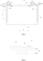
FIG. 3 is a cross sectional view of the secondary battery ofFIG. 2 . -
FIG. 4 is a schematic view of a first connecting piece and a second electrode terminal after welded. -
FIG. 5 is a schematic view of the first connecting piece and a first electrode terminal after welded. -
FIG. 6 is a schematic view of the first connecting piece of the battery module according to the present invention. -
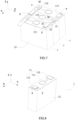
FIG. 7 is a schematic view of another embodiment of the battery module according to the present invention. -
FIG. 8 is a schematic view of the secondary battery shown inFIG. 7 . -
FIG. 9 is a schematic view of still another embodiment of the battery module according to the present invention. -
FIG. 10 is a schematic view of the secondary battery shown inFIG. 9 . -
FIG. 11 is a schematic view of further another embodiment of the battery module according to the present invention. -
FIG. 12 is a cross sectional view of the secondary battery shown inFIG. 11 . -
FIG. 13 is a schematic view of a first sealing member of a battery cap assembly according to the present invention. -
FIG. 14 is a schematic view of a second sealing member of the battery cap assembly according to the present invention. - Reference numerals in figures are represented as follows:
- 1 secondary battery
- 11 battery cap assembly
- 111 cap plate
- 1111 first terminal hole
- 1112 second terminal hole
- 112 first electrode terminal
- 1121 first protruding portion
- 1122 first base portion
- 113 second electrode terminal
- 1131 second protruding portion
- 1132 second base portion
- 114 first sealing member
- 1141 first main portion
- 1142 first extending portion
- 115 second sealing member
- 1151 second main portion
- 1152 second extending portion
- 116 adapter piece
- 111 cap plate
- 12 case
- 13 electrode assembly
- 11 battery cap assembly
- 2 first connecting piece
- 21 first connecting portion
- 22 second connecting portion
221 third through-hole - 23 third connecting portion
- 3 second connecting piece
- M welding portion
- P protrusion
- S upper surface
- H1 first through-hole
- H2 second through-hole
- X transverse direction
- Y longitudinal direction
- Z up-down direction
- Hereinafter a non-claimed battery cap assembly, a non-claimed secondary battery and a battery module according to any of claims 1-9 the present invention will be described in detail in combination with the figures.
- Firstly, a non-claimed battery cap assembly will be described.
- Referring to
FIGs. 1-14 , abattery cap assembly 11 according to the present invention comprises acap plate 111, afirst electrode terminal 112 and afirst sealing member 114. Thecap plate 111 includes a firstterminal hole 1111. Thefirst electrode terminal 112 includes a first protrudingportion 1121 protruding above thecap plate 111 and afirst base portion 1122 connected with a bottom surface of the first protrudingportion 1121, thefirst base portion 1122 extends downwardly and extends into the firstterminal hole 1111, a cross-sectional area of the first protrudingportion 1121 is larger than a cross-sectional area of the firstterminal hole 1111. Thefirst sealing member 114 includes a firstmain portion 1141 provided between the first protrudingportion 1121 and thecap plate 111, the firstmain portion 1141 includes a first through-hole H1 through which thefirst base portion 1122 passes. The first protrudingportion 1121 of thefirst electrode terminal 112 is used for welding with a first connectingpiece 2 to form a welding portion M, and a projection of the welding portion M in an up-down direction Z is positioned in the first through-hole H1 of the firstmain portion 1141. - Because the cross-sectional area of the first protruding
portion 1121 is larger than the cross-sectional area of the firstterminal hole 1111, the first protrudingportion 1121 can be clamped above the firstterminal hole 1111, thereby avoiding the first protrudingportion 1121 of thefirst electrode terminal 112 passing through the firstterminal hole 1111. At the same time, the first protrudingportion 1121 can be in the shape of flat plate, and the firstmain portion 1141 of thefirst sealing member 114 is interposed between the first protrudingportion 1121 and thecap plate 111 in the up-down direction Z, so that the firstterminal hole 1111 is sealed from above. A top surface of the first protrudingportion 1121 can be a plane, the first connectingpiece 2 is welded with the top surface of the first protrudingportion 1121. - When the
first electrode terminal 112 of thebattery cap assembly 11 needs to be connected with the first connectingpiece 2, the first protrudingportion 1121 can be directly fixed to the first connectingpiece 2 by laser penetration welding. The projection of the welding portion M in the up-down direction Z formed in the process of welding is positioned in the first through-hole H1 of the firstmain portion 1141, heat generated in the process of welding is firstly transferred to a part of the first protrudingportion 1121 positioned above the firstmain portion 1141 and then transferred to the firstmain portion 1141 downwardly, rather than directly transferred to the firstmain portion 1141 downwardly, therefore, thebattery cap assembly 11 of the present invention can increase heat transfer path in the process of welding, decrease the heat transferred to firstmain portion 1141, reduce risk that the firstmain portion 1141 of thefirst sealing member 114 is damaged by high temperature, improve sealing performance and safety performance of thebattery cap assembly 11. - Referring to
FIG. 3 , thefirst sealing member 114 further includes a first extendingportion 1142, the first extendingportion 1142 extends downwardly from a bottom surface of the firstmain portion 1141, extends into the firstterminal hole 1111 and is interposed between thefirst base portion 1122 and a wall of firstterminal hole 1111. Referring toFIG. 13 , the first through-hole H1 of the firstmain portion 1141 passes through the first extendingportion 1142. The first extendingportion 1142 helps position thefirst sealing member 114 in the process of assembling. - Referring to
FIG. 5 , the projection of the welding portion M in the up-down direction Z is preferably positioned in a cross-section of thefirst base portion 1122. Thefirst base portion 1122 needs to extend into the firstterminal hole 1111, so thefirst base portion 1122 has a larger thickness relative to the first protrudingportion 1121; in the process of welding, the welding portion M may extend to thefirst base portion 1122, thereby ensuring welding depth of the laser penetration welding and connecting strength between thefirst electrode terminal 112 and the first connectingpiece 2. At the same time, the projection of the welding portion M in the up-down direction Z is positioned in the cross-section of thefirst base portion 1122, so a thickness of the first protrudingportion 1121 protruding above thecap plate 111 can be decreased, thereby reducing an entire height of thebattery cap assembly 11; in addition, thefirst base portion 1122 can further increase heat dissipating area in the process of welding, thereby enhancing heat dissipating speed, reducing risk that the firstmain portion 1141 of thefirst sealing member 114 is damaged by high temperature, improving the sealing performance and the safety performance of thebattery cap assembly 11, a later mentioned secondary battery and a later mentioned battery module. In addition, the firstterminal hole 1111 is sealed by the firstmain portion 1141 of thefirst sealing member 114, therefore, even if the heat in thefirst base portion 1122 is transferred to the first extendingportion 1142, it will not affect the sealing performance. - Referring to
FIG. 1 andFIG. 5 , the projection of the welding portion M in the up-down direction Z at least includes a circular arc, preferably, the welding portion M is in the shape of annulus. The electrical current can flow between thefirst electrode terminal 112 and the first connectingpiece 2 via the welding portion M. When a width of the welding portion M formed by welding is constant, an overcurrent area of the welding portion M depends on an extending length of the welding portion M. If the overcurrent area is constant, compared to the welding portion M in the shape of straight line, the welding portion M in the shape of circular arc can take advantage of length space and width space of thefirst electrode terminal 112 at the same time, which can lower the requirement of length and width of theelectrode terminal 112. - Referring to
FIG. 3 , thebattery cap assembly 11 further comprises asecond electrode terminal 113 and asecond sealing member 115, thecap plate 111 further includes a secondterminal hole 1112. Thesecond electrode terminal 113 includes asecond protruding portion 1131 protruding above thecap plate 111 and asecond base portion 1132 connected with a bottom surface of the second protrudingportion 1131; thesecond base portion 1132 extends downwardly and extends into the secondterminal hole 1112, a cross-sectional area of the second protrudingportion 1131 is larger than a cross-sectional area of the secondterminal hole 1112. Thesecond sealing member 115 includes a secondmain portion 1151 provided between the second protrudingportion 1131 and thecap plate 111, the secondmain portion 1151 includes a second through-hole H2 through which thesecond base portion 1132 passes. - Because the cross-sectional area of the second protruding
portion 1131 is larger than the cross-sectional area of the secondterminal hole 1112, the second protrudingportion 1131 can be clamped above the secondterminal hole 1112, thereby avoiding the second protrudingportion 1131 of thesecond electrode terminal 113 passing through the secondterminal hole 1112. At the same time, the secondmain portion 1151 of thesecond sealing member 115 is interposed between the second protrudingportion 1131 and thecap plate 111 in the up-down direction Z, so that the secondterminal hole 1112 can be sealed from above. - The
second electrode terminal 113 is used for connecting with a second connectingpiece 3. - Specifically, in an embodiment, referring to
FIG. 11 and FIG. 12 , an upper surface S of the second protrudingportion 1131 is a plane. When thesecond electrode terminal 113 of thebattery cap assembly 11 needs to be connected with the second connectingpiece 3, the second connectingpiece 3 can be directly fixed to the second protrudingportion 1131 by laser penetration welding. A welding portion M is formed by welding the second protruding portion - 1131 of the
second electrode terminal 113 and the second connectingpiece 3, and a projection of the welding portion M in the up-down direction Z is positioned in the second through-hole H2 of the secondmain portion 1151, preferably positioned in a cross-section of thesecond base portion 1132. Thebattery cap assembly 11 of the embodiment can increase heat transfer path in the process of welding, decrease heat transferred to the secondmain portion 1151, reduce risk that the secondmain portion 1151 of thesecond sealing member 115 is damaged by high temperature, and improve the sealing performance and the safety performance of thebattery cap assembly 11. - Referring to
FIG. 3 , thesecond sealing member 115 further includes a second extendingportion 1152, the second extendingportion 1152 extends downwardly from a bottom surface of the secondmain portion 1151, extends into the secondterminal hole 1112 and is interposed between thesecond base portion 1132 and a wall of the secondterminal hole 1112. Referring toFIG. 14 , the second through-hole H2 of the secondmain portion 1151 passes through the second extendingportion 1152. The second extendingportion 1152 helps position thesecond sealing member 115 in the process of assembling. - In another embodiment, referring to
FIGs. 1-4 , a protrusion P is formed on the upper surface S of the second protrudingportion 1131 and used for welding with the second connectingpiece 3. Because the protrusion P is provided on the upper surface S of the second protrudingportion 1131, when thesecond electrode terminal 113 of thebattery cap assembly 11 needs to be connected with the second connectingpiece 3, the protrusion P can be directly fixed to the second connectingpiece 3 by butt welding; compared to the traditional laser penetration welding, the butt welding can effectively decrease the heat generated in the process of welding and avoid thesecond sealing member 115 being damaged by high temperature. - The first connecting
piece 2 can further be used for connecting thefirst electrode terminal 112 of a first one of thebattery cap assemblies 11 and thesecond electrode terminal 113 of a second one of thebattery cap assemblies 11, so as to electrically connect the twobattery cap assemblies 11. Similarly, the second connectingpiece 3 can further be used for connecting thesecond electrode terminal 113 of the first one of thebattery cap assemblies 11 and thefirst electrode terminal 112 of a third one of thebattery cap assemblies 11, so as to electrically connect the twobattery cap assemblies 11. The first connectingpiece 2 and the second connectingpiece 3 are the same. - For example, when one first connecting
piece 2 needs to connect thefirst electrode terminal 112 of the first one of thebattery cap assemblies 11 and thesecond electrode terminal 113 of the second one of thebattery cap assemblies 11, the first connectingpiece 2 can be connected with the first protrudingportion 1121 of thefirst electrode terminal 112 by laser penetration welding, and the welding position is flexible, so it only needs to ensure that the first connectingpiece 2 is fitted with the protrusion P of the second one of thebattery cap assemblies 11 in the process of assembling the first connectingpiece 2; even if there is a dimension tolerance between the twobattery cap assemblies 11, thefirst electrode terminal 112 of the first one of thebattery cap assemblies 11 will not limit the positioning and assembling of the first connectingpiece 2, which can ensure the connecting strength between the first connectingpiece 2 and the twobattery cap assemblies 11. - Shape of the protrusion P depends on actual demand, for example, the protrusion P is in the shape of stripe. Specifically, in an embodiment, referring to
FIG. 8 , a cross-section of the protrusion P is a rectangle and the protrusion P extends along a transverse direction X of thecap plate 111, a width of the protrusion P in a longitudinal direction Y ranges from 0.5mm to 3mm. In another embodiment, referring toFIG. 10 , the cross-section of the protrusion P is a rectangle and the protrusion P extends along the longitudinal direction Y, a width of the protrusion P in the transverse direction X ranges from 0.5mm to 3mm. - The protrusion P also can be provided on different positions of the upper surface S, for example, the protrusion P can be positioned in a middle part of the upper surface S or at an edge of the upper surface S.
- In the up-down direction Z, both of a thickness of the first protruding
portion 1121 and a thickness of the second protrudingportion 1131 range from 0.01mm to 2mm, preferably, the thickness of the first protrudingportion 1121 is equal to the thickness of the second protrudingportion 1131. The protrusion P is provided on the second protrudingportion 1131, and there is no need to weld the second protrudingportion 1131 and the second connectingpiece 3, so the second protrudingportion 1131 can have a small thickness. Because the projection of the welding portion M formed by welding the first protrudingportion 1121 and the first connectingpiece 2 in the up-down direction Z is positioned in the cross-section of thefirst base portion 1122, the first protrudingportion 1121 can have a small thickness. - The
first electrode terminal 112 can be a positive electrode terminal and made of aluminum, thesecond electrode terminal 113 can be a negative electrode terminal and made of copper, and a cross-sectional area of thesecond base portion 1132 is smaller than a cross-sectional area of thefirst base portion 1122. - The
battery cap assembly 11 of the present invention is generally applied to the later mentionedsecondary battery 1, the first electrode terminal 112 (positive electrode terminal) and the second electrode terminal 113 (negative electrode terminal) can transfer the electric energy of thesecondary battery 1 to outside via a positive electrode plate (a later mentioned first electrode plate) and a negative electrode plate (a later mentioned second electrode plate) respectively. Considering electrochemistry, a current collector of the positive electrode plate is formed by aluminum foil, and a current collector of the negative electrode plate is formed by copper foil. It is difficult to connect aluminum and copper by laser welding, so in order to ensure the connecting strength between thefirst electrode terminal 112 and the positive electrode plate and the connecting strength betweensecond electrode terminal 113 and the negative electrode plate, thefirst electrode terminal 112 is preferably made of aluminum, thesecond electrode terminal 113 is preferably made of copper. - Because the protrusion P is provided on the upper surface S of the
second electrode terminal 113, when thesecond electrode terminal 113 of thebattery cap assembly 11 needs to be connected with second connectingpiece 3, the protrusion P can be directly fixed to the second connectingpiece 3 by butt welding; compared to the traditional laser penetration welding, the butt welding can effectively decrease the heat generated in the process of welding and avoid thesecond sealing member 115 being damaged by high temperature. In addition, compared to aluminum, copper needs more energy and generates more heat in the process of welding, so thesecond electrode terminal 113 made of copper needs to choose the butt welding generating few heat. In addition, because electrical resistance of copper is lower than electrical resistance of aluminum, based on the premise that the overcurrent ability of thefirst electrode terminal 112 and the overcurrent ability of thesecond electrode terminal 113 are consistent, the cross-sectional area of thesecond base portion 1132 can be decreased, which can reduce weight of thesecondary battery 1 and improve energy density. At the same time, the price of copper is higher than the price of aluminum, so it can save amount of copper and reduce cost. - The
cap plate 111 can be made of insulating material. Thebattery cap assembly 11 further comprises twoadapter pieces 116, oneadapter piece 116 is attached to a bottom surface of thecap plate 111 and welded with thefirst base portion 1122, theother adapter piece 116 is attached to the bottom surface of thecap plate 11 and welded with thesecond base portion 1132. Because thecap plate 111 is made of the insulating material, the twoadapter pieces 116 can be directly attached to the bottom surface of thecap plate 111, and there is no need to provide an insulating member between thecap plate 111 and theadapter piece 116, which can save space. - In addition, a cross-section of the first protruding
portion 1121, the cross-section of thefirst base portion 1122, a cross-section of the second protrudingportion 1131, the cross-section of thesecond base portion 1132, a cross-section of the firstterminal hole 1111 and a cross-section of the secondterminal hole 1112 are sections perpendicular to the up-down direction Z, and the cross-sectional area is area of the section perpendicular to the up-down direction Z. - Secondly, a non-claimed secondary battery will be described.
- Referring to
FIGs. 1-14 , asecondary battery 1 according to the present invention comprises acase 12, thebattery cap assembly 11 according to the first aspect of the present invention and anelectrode assembly 13. Thecase 12 has an opening in a top thereof. Thecap plate 111 of thebattery cap assembly 11 is fixed to thecase 12 and seals the opening of thecase 12. Theelectrode assembly 13 is received in thecase 12 and electrically connected with thefirst electrode terminal 112. - Referring to
FIG. 2 , thesecondary battery 1 can be a prismatic rechargeable battery; certainly, thesecondary battery 1 also can have other shapes. Correspondingly, thecase 12 can have a hexahedral shape, a cavity is formed in thecase 12, and theelectrode assembly 13 can be assembled into thecase 12 via the opening of thecase 12. - One opening is provided in the top of the
case 12, thebattery cap assembly 11 of thesecondary battery 1 of the present invention only comprises onecap plate 111; thefirst electrode terminal 112, thesecond electrode terminal 113, thefirst sealing member 114 and thesecond sealing member 115 are provided to the onecap plate 111. Alternatively, two openings are respectively provided in the top of thecase 12 and the bottom of thecase 12, thebattery cap assembly 11 of thesecondary battery 1 of the present invention comprises twocap plates 111; onecap plate 111 seals the opening in the top of thecase 12, and thefirst electrode terminal 112 and thefirst sealing member 114 are provided to the onecap plate 111; theother cap plate 111 seals the opening in the bottom of thecase 12, and thesecond electrode terminal 113 and thesecond sealing member 115 are provided to theother cap plate 111. - The
electrode assembly 13 can comprise a first electrode plate, a second electrode plate and a separator separating the first electrode plate and the second electrode plate. The first electrode plate and the second electrode plate are opposite in polarity. Each of the first electrode plate and the second electrode plate comprises the current collector and an active material coated on the surface of the current collector, the current collector can be metal foil. The first electrode plate of theelectrode assembly 13 can be electrically connected with thefirst electrode terminal 112 via oneadapter piece 116, the second electrode plate of theelectrode assembly 13 can be electrically connected with thesecond electrode terminal 113 via theother adapter piece 116. - The
first electrode terminal 112 extends into thecase 12 via the firstterminal hole 1111, and is electrically connected with theelectrode assembly 13 in thecase 12; thesecond electrode terminal 113 extends into thecase 12 via the secondterminal hole 1112, and is electrically connected with theelectrode assembly 13 in thecase 12. - Preferably, the first electrode plate is the positive electrode plate, and the current collector of the first electrode plate is made of aluminum in general; correspondingly, the second electrode plate is the negative electrode plate, and the current collector of the second electrode plate is made of copper in general. Because it is difficult to welding different metals, especially copper and aluminum,
first electrode terminal 112 is preferably made of aluminum and thesecond electrode terminal 113 is preferably made of copper. - Finally, a battery module according to the claim set of the present invention will be described.
- Referring to
FIGs. 1-14 , a battery module of the present invention comprises the first connectingpiece 2 and thesecondary batteries 1 according to the second aspect of the present invention, the first connectingpiece 2 is welded with the first protrudingportion 1121 of thefirst electrode terminal 112 of thebattery cap assembly 11 of thesecondary battery 1 to form the welding portion M, the projection of the welding portion M in the up-down direction Z is positioned in the first through-hole H1 of the firstmain portion 1141. - The
secondary batteries 1 are arranged in a row, two adjacentsecondary batteries 1 can be electrically connected by one connecting piece (such as the first connecting piece 2). For example, when the two adjacentsecondary batteries 1 need to be connected in series, the first connectingpiece 2 connects thefirst electrode terminal 112 of onesecondary battery 1 and thesecond electrode terminal 113 of the othersecondary battery 1; when the two adjacentsecondary batteries 1 need to be connected in parallel, the first connectingpiece 2 connects thefirst electrode terminals 112 of the two adjacentsecondary batteries 1 or thesecond electrode terminals 11 of the two adjacentsecondary batteries 1. - Hereinafter the battery module comprising the
secondary batteries 1 connected in series will be described. - Referring to
FIG. 1 andFIG. 6 , the first connectingpiece 2 includes a first connectingportion 21 and a second connectingportion 22; the first connectingportion 21 is welded with the first protrudingportion 1121 of thefirst electrode terminal 112 of thebattery cap assembly 11 of onesecondary battery 1, the second connectingportion 22 is welded with the protrusion P of the second protrudingportion 1131 of thesecond electrode terminal 113 of thebattery cap assembly 11 of another secondary battery 1 (certainly, the protrusion P can be omitted and the second connectingportion 22 can be directly welded with the upper surface S of the protruding portion 1131). - The process of assembling the battery module is as follows: firstly, arranging the
secondary batteries 1 in a row; secondly, attaching the first connectingportion 21 of the first connectingpiece 2 to the top surface of the first protrudingportion 1121 of thefirst electrode terminal 112 of thebattery cap assembly 11 of onesecondary battery 1, and attaching the second connectingportion 22 to the upper surface S and the protrusion P of the second protrudingportion 1131 of thesecond electrode terminal 113 of thebattery cap assembly 11 of anothersecondary battery 1; thirdly, referring toFIG. 4 , welding along a contacting boundary between the second connectingportion 22 and the protrusion P, thereby fixing the first connectingpiece 2 to the anothersecondary battery 1; referring toFIG. 5 , connecting the first connectingportion 21 with the first protrudingportion 1121 of thefirst electrode terminal 112 of thebattery cap assembly 11 of the onesecondary battery 1 directly by laser penetration welding; finally, repeating aforementioned steps, and circularly welding a plurality of connecting pieces (such as the second connectingpiece 3, a third connecting piece and the like) to connect all thesecondary batteries 1. - In the process of assembling the battery module according to the present invention, the welding portion M is formed by welding the first protruding
portion 1121 of thefirst electrode terminal 112 of thebattery cap assembly 11 of thesecondary battery 1 and the first connectingpiece 2, and the projection of the welding portion M in the up-down direction Z is positioned in the first through-hole H1 of the firstmain portion 1141 of thefirst sealing member 114. The heat generated in the process of welding is firstly transferred to the part of the first protrudingportion 1121 positioned above the firstmain portion 1141 and then transferred downwardly to the firstmain portion 1141, rather than directly transferred downwardly to the firstmain portion 1141, therefore, the battery module of the present invention can increase heat transfer path in the process of welding, decrease the heat transferred to firstmain portion 1141, reduce risk that the firstmain portion 1141 of thefirst sealing member 114 is damaged by high temperature, improve the sealing performance and the safety performance of thebattery cap assembly 11, thesecondary battery 1 and the battery module. - Referring to
FIG. 1 andFIG. 6 , the first connectingpiece 2 further includes a third connectingportion 23 in the shape of arch, the third connectingportion 23 connects the first connectingportion 21 and the second connectingportion 22. The third connectingportion 23 in the shape of arch can adjust a height difference between the first connectingportion 21 and the second connectingportion 22 in the up-down direction Z. - Referring to
FIG. 1 andFIG. 6 , the second connectingportion 22 includes a third through-hole 221 fitted with the protrusion P of thesecondary battery 1, the protrusion P of thesecondary battery 1 can be fixed to the third through-hole 221 by laser welding. By providing the third through-hole 221, it can increase a length of welding seam between the second connectingportion 22 and the protrusion P and improve welding strength. - In addition, in the battery module according to the present invention, the protrusion P and the second connecting
portion 22 of the first connectingpiece 2 are arranged side by side, so the protrusion P will not increase the height of the battery module; at the same time, the second connectingportion 22 of the first connectingpiece 2 is fixed to the protrusion P by butt welding, and there is no need to fix the second connectingportion 22 of the first connectingpiece 2 to the upper surface S of thesecond electrode terminal 113 by laser penetration welding, which can lower the requirement of a thickness of thesecond electrode terminal 113, decrease the thickness of thesecond electrode terminal 113 and save material, reduce the total height of thesecond electrode terminal 113 and the first connectingpiece 2 assembled together, improve the energy density of the battery module. In addition, the first protrudingportion 1121 of thefirst electrode terminal 112 is directly connected with the first connectingportion 21 by laser penetration welding, therefore, it only needs to ensure that the second connectingportion 22 of the first connectingpiece 2 is fitted with the protrusion P in the process of assembling the first connectingpiece 2; even if the dimension tolerances of thesecondary batteries 1 accumulate, the first protrudingportion 1121 of thefirst electrode terminal 112 will not limit the positioning and assembling of the first connectingpiece 2, which can ensure the connecting strength between the first connectingpiece 2 and twosecondary batteries 1, and increase cycle life. - Preferably, the
first electrode terminal 112 is made of aluminum, thesecond electrode terminal 113 is made of copper, and the cross-sectional area of thesecond base portion 1132 is smaller than the cross-sectional area of thefirst base portion 1122. - The protrusion P is provided on the upper surface S of the
second electrode terminal 113 and fixed to the second connectingportion 22 of the first connectingpiece 2 by butt welding; compared to the traditional laser penetration welding, the butt welding can effectively decrease the heat generated in the process of welding and avoid thesecond sealing member 115 between thesecond electrode terminal 113 and thecap plate 111 being damaged by high temperature. In addition, compared to aluminum, copper needs more energy and generates more heat in the process of welding, so thesecond electrode terminal 113 made of copper needs to choose the butt welding generating few heat. In addition, because the electrical resistance of copper is lower than the electrical resistance of aluminum, based on the premise that the overcurrent ability of thefirst electrode terminal 112 and the overcurrent ability of thesecond electrode terminal 113 are consistent, the cross-sectional area of thesecond base portion 1132 of thesecond electrode terminal 113 can be decreased, which can reduce weight of thesecondary battery 1 and improve energy density. At the same time, the price of copper is higher than the price of aluminum, so it can save amount of copper and reduce cost.
Claims (9)
- A battery module, wherein the battery module comprises a first connecting piece (2) and secondary batteries (1);the secondary battery (1) comprises a battery cap assembly (11), a case (12) and an electrode assembly (13), the case (12) has an opening in a top thereof, the battery cap assembly (11) is fixed to the case (12) and seals the opening of the case (12), the electrode assembly (13) is received in the case (12);the battery cap assembly (11) comprises a cap plate (111), a first electrode terminal (112) and a first sealing member (114), the electrode assembly (13) is electrically connected with the first electrode terminal (112);the cap plate (111) includes a first terminal hole (1111);a first electrode terminal (112) includes a first protruding portion (1121) protruding above the cap plate (111) and a first base portion (1122) connected with the first protruding portion (1121), the first base portion (1122) extends into the first terminal hole (1111), a cross-sectional area of the first protruding portion (1121) is larger than a cross-sectional area of the first terminal hole (1111);the first sealing member (114) includes a first main portion (1141) provided between the first protruding portion (1121) and the cap plate (111), the first main portion (1141) includes a first through-hole (H1) through which the first base portion (1122) passes;characterized in thatthe first connecting piece (2) is welded with the first protruding portion (1121) of the first electrode terminal (112) of the battery cap assembly (11) of the secondary battery (1) to form a welding portion (M), the projection of the welding portion (M) in an up-down direction (Z) is positioned in the first through-hole (H1) of the first main portion (1141), and the welding portion (M) extends to the first base portion (1122).
- The battery module according to claim 1, wherein the first base portion (1122) is connected with a bottom surface of the first protruding portion (1121) and extends downwardly.
- The battery module according to claim 1, wherein
the first sealing member (114) further includes a first extending portion (1142), the first extending portion (1142) extends downwardly from a bottom surface of the first main portion (1141), extends into the first terminal hole (1111) and is interposed between the first base portion (1122) and a wall of first terminal hole (1111). - The battery module according to claim 1, wherein
the projection of the welding portion (M) in the up-down direction (Z) is positioned in a cross-section of the first base portion (1122). - The battery module according to claim 1, wherein
the projection of the welding portion (M) in the up-down direction (Z) at least includes a circular arc. - The battery module according to any one of claims 1-5, whereinthe battery cap assembly (11) further comprises a second electrode terminal (113) and a second sealing member (115), the cap plate (111) further includes a second terminal hole (1112);the second electrode terminal (113) includes a second protruding portion (1131) protruding above the cap plate (111) and a second base portion (1132) connected with a bottom surface of the second protruding portion (1131); the second base portion (1132) extends downwardly and extends into the second terminal hole (1112), a cross-sectional area of the second protruding portion (1131) is larger than a cross-sectional area of the second terminal hole (1112);the second sealing member (115) includes a second main portion (1151) provided between the second protruding portion (1131) and the cap plate (111), the second main portion (1151) includes a second through-hole (H2) through which the second base portion (1132) passes.
- The battery module according to claim 6, whereinthe battery module further comprises a second connecting piece (3);a protrusion (P) is formed on an upper surface (S) of the second protruding portion (1131) and welded with the second connecting piece (3).
- The battery module according to claim 7, whereina cross-section of the protrusion (P) is a rectangle and the protrusion (P) extends along a transverse direction (X) of the cap plate (111); ora cross-section of the protrusion (P) is a rectangle and the protrusion (P) extends along a longitudinal direction (Y).
- The battery module according to claim 6, wherein
the first electrode terminal (112) is a positive electrode terminal and made of aluminum, the second electrode terminal (113) is a negative electrode terminal and made of copper, and a cross-sectional area of the second base portion (1132) is smaller than a cross-sectional area of the first base portion (1122).
Applications Claiming Priority (1)
| Application Number | Priority Date | Filing Date | Title |
|---|---|---|---|
| CN201810025795.XA CN110034269B (en) | 2018-01-11 | 2018-01-11 | Battery top cap subassembly, secondary cell and battery module |
Publications (2)
| Publication Number | Publication Date |
|---|---|
| EP3511994A1 EP3511994A1 (en) | 2019-07-17 |
| EP3511994B1 true EP3511994B1 (en) | 2024-07-10 |
Family
ID=62165428
Family Applications (1)
| Application Number | Title | Priority Date | Filing Date |
|---|---|---|---|
| EP18172071.5A Active EP3511994B1 (en) | 2018-01-11 | 2018-05-14 | Battery cap assembly, secondary battery and battery module |
Country Status (4)
| Country | Link |
|---|---|
| US (1) | US10811643B2 (en) |
| EP (1) | EP3511994B1 (en) |
| CN (1) | CN110034269B (en) |
| HU (1) | HUE068341T2 (en) |
Families Citing this family (4)
| Publication number | Priority date | Publication date | Assignee | Title |
|---|---|---|---|---|
| KR20220054130A (en) * | 2020-10-23 | 2022-05-02 | 삼성에스디아이 주식회사 | Secondary battery |
| CN115769432A (en) * | 2021-03-01 | 2023-03-07 | 日本汽车能源株式会社 | Battery pack and battery pack manufacturing method |
| CN113922001A (en) * | 2021-09-29 | 2022-01-11 | 珠海冠宇电池股份有限公司 | Switching piece and battery |
| CN114361667A (en) * | 2022-01-04 | 2022-04-15 | 湖北亿纬动力有限公司 | Top cover assembly, assembly method of top cover assembly and battery |
Family Cites Families (16)
| Publication number | Priority date | Publication date | Assignee | Title |
|---|---|---|---|---|
| US5308719A (en) * | 1992-09-21 | 1994-05-03 | Globe-Union Inc. | Lead acid batteries containing center lug plates and high performance cast-on straps |
| JP4124756B2 (en) * | 2003-10-03 | 2008-07-23 | 日立マクセル株式会社 | Sealed battery |
| EP2215674B1 (en) * | 2007-11-30 | 2017-06-07 | A123 Systems LLC | Battery cell design with asymmetrical terminals |
| KR101574083B1 (en) * | 2008-12-22 | 2015-12-04 | 삼성에스디아이 주식회사 | Rechargeable battery |
| JP5595830B2 (en) * | 2009-08-26 | 2014-09-24 | 株式会社東芝 | Battery, assembled battery, and method of manufacturing assembled battery |
| US8263255B2 (en) | 2009-10-01 | 2012-09-11 | Sb Limotive Co., Ltd. | Rechargeable battery and battery module |
| CN102110798B (en) | 2009-12-28 | 2015-04-08 | 三星Sdi株式会社 | Battery module |
| KR101165514B1 (en) * | 2010-01-27 | 2012-07-16 | 에스비리모티브 주식회사 | Rechargeable battery |
| KR101254871B1 (en) * | 2011-04-18 | 2013-04-15 | 로베르트 보쉬 게엠베하 | Secondary battery |
| KR101715955B1 (en) * | 2011-11-09 | 2017-03-28 | 삼성에스디아이 주식회사 | Secondary bttery |
| JP5976340B2 (en) * | 2012-02-29 | 2016-08-23 | 三洋電機株式会社 | Method for manufacturing prismatic secondary battery |
| KR101794096B1 (en) | 2013-04-16 | 2017-11-06 | 삼성에스디아이 주식회사 | Rechargeable battery module with bus bar |
| JP6176524B2 (en) * | 2013-06-25 | 2017-08-09 | 株式会社Gsユアサ | Power storage device and method for manufacturing power storage device |
| KR102084098B1 (en) * | 2013-09-23 | 2020-03-04 | 삼성에스디아이 주식회사 | Battery module having holder |
| CN106575741A (en) * | 2014-08-06 | 2017-04-19 | 日立汽车系统株式会社 | Rectangular secondary battery |
| CN207818742U (en) * | 2018-01-11 | 2018-09-04 | 宁德时代新能源科技股份有限公司 | Battery top cover assembly, secondary battery and battery module |
-
2018
- 2018-01-11 CN CN201810025795.XA patent/CN110034269B/en active Active
- 2018-05-02 US US15/969,652 patent/US10811643B2/en active Active
- 2018-05-14 EP EP18172071.5A patent/EP3511994B1/en active Active
- 2018-05-14 HU HUE18172071A patent/HUE068341T2/en unknown
Also Published As
| Publication number | Publication date |
|---|---|
| US20190214612A1 (en) | 2019-07-11 |
| US10811643B2 (en) | 2020-10-20 |
| CN110034269B (en) | 2024-04-05 |
| HUE068341T2 (en) | 2024-12-28 |
| CN110034269A (en) | 2019-07-19 |
| EP3511994A1 (en) | 2019-07-17 |
Similar Documents
| Publication | Publication Date | Title |
|---|---|---|
| EP2228852B1 (en) | Rechargeable battery comprising current collecting plates with improved structure | |
| EP2204863B1 (en) | Battery module | |
| KR101107082B1 (en) | Secondary battery | |
| JP5414476B2 (en) | Secondary battery | |
| EP2887427A1 (en) | Battery module with bus-bar holder | |
| EP3511994B1 (en) | Battery cap assembly, secondary battery and battery module | |
| KR101147175B1 (en) | Rechargeable battery | |
| CN207818742U (en) | Battery top cover assembly, secondary battery and battery module | |
| KR101912004B1 (en) | Lithium secondary battery with improved safety by using bimetal tab | |
| US8790803B2 (en) | Rechargeable battery | |
| KR20150047417A (en) | Rechargeable battery having fuse and battery module | |
| JP5044108B2 (en) | Battery connection device | |
| KR20120002406A (en) | Secondary battery | |
| US9543561B2 (en) | Battery | |
| US20220384915A1 (en) | Non-aqueous electrolyte secondary battery | |
| EP3474342B1 (en) | Battery cap assembly and secondary battery | |
| KR100786871B1 (en) | Secondary battery | |
| EP3511995B1 (en) | Battery cap assembly, secondary battery and battery module | |
| KR20110128483A (en) | Battery pack | |
| US11050116B2 (en) | Secondary battery | |
| KR101733741B1 (en) | Rechargeable battery having connecting member | |
| KR102371195B1 (en) | Rechargeable Mattery And Rechargeable battery Module Using The Same | |
| KR20250039641A (en) | secondary battery | |
| KR20260059064A (en) | Battery pack | |
| KR20250045626A (en) | Secondary battery |
Legal Events
| Date | Code | Title | Description |
|---|---|---|---|
| PUAI | Public reference made under article 153(3) epc to a published international application that has entered the european phase |
Free format text: ORIGINAL CODE: 0009012 |
|
| STAA | Information on the status of an ep patent application or granted ep patent |
Free format text: STATUS: REQUEST FOR EXAMINATION WAS MADE |
|
| 17P | Request for examination filed |
Effective date: 20180514 |
|
| AK | Designated contracting states |
Kind code of ref document: A1 Designated state(s): AL AT BE BG CH CY CZ DE DK EE ES FI FR GB GR HR HU IE IS IT LI LT LU LV MC MK MT NL NO PL PT RO RS SE SI SK SM TR |
|
| AX | Request for extension of the european patent |
Extension state: BA ME |
|
| STAA | Information on the status of an ep patent application or granted ep patent |
Free format text: STATUS: EXAMINATION IS IN PROGRESS |
|
| 17Q | First examination report despatched |
Effective date: 20231026 |
|
| REG | Reference to a national code |
Ref legal event code: R079 Free format text: PREVIOUS MAIN CLASS: H01M0002040000 Ipc: H01M0050176000 Ref country code: DE Ref legal event code: R079 Ref document number: 602018071503 Country of ref document: DE Free format text: PREVIOUS MAIN CLASS: H01M0002040000 Ipc: H01M0050176000 |
|
| RIC1 | Information provided on ipc code assigned before grant |
Ipc: H01M 50/184 20210101ALI20240304BHEP Ipc: H01M 50/147 20210101ALI20240304BHEP Ipc: H01M 50/176 20210101AFI20240304BHEP |
|
| GRAP | Despatch of communication of intention to grant a patent |
Free format text: ORIGINAL CODE: EPIDOSNIGR1 |
|
| STAA | Information on the status of an ep patent application or granted ep patent |
Free format text: STATUS: GRANT OF PATENT IS INTENDED |
|
| INTG | Intention to grant announced |
Effective date: 20240417 |
|
| GRAS | Grant fee paid |
Free format text: ORIGINAL CODE: EPIDOSNIGR3 |
|
| GRAA | (expected) grant |
Free format text: ORIGINAL CODE: 0009210 |
|
| STAA | Information on the status of an ep patent application or granted ep patent |
Free format text: STATUS: THE PATENT HAS BEEN GRANTED |
|
| AK | Designated contracting states |
Kind code of ref document: B1 Designated state(s): AL AT BE BG CH CY CZ DE DK EE ES FI FR GB GR HR HU IE IS IT LI LT LU LV MC MK MT NL NO PL PT RO RS SE SI SK SM TR |
|
| REG | Reference to a national code |
Ref country code: CH Ref legal event code: EP |
|
| REG | Reference to a national code |
Ref country code: DE Ref legal event code: R096 Ref document number: 602018071503 Country of ref document: DE |
|
| REG | Reference to a national code |
Ref country code: DE Ref legal event code: R081 Ref document number: 602018071503 Country of ref document: DE Owner name: CONTEMPORARY AMPEREX TECHNOLOGY (HONG KONG) LI, HK Free format text: FORMER OWNER: CONTEMPORARY AMPEREX TECHNOLOGY CO., LIMITED, NINGDE CITY, FUJIAN, CN |
|
| REG | Reference to a national code |
Ref country code: NL Ref legal event code: PD Owner name: CONTEMPORARY AMPEREX TECHNOLOGY (HONG KONG) LIMITED; CN Free format text: DETAILS ASSIGNMENT: CHANGE OF OWNER(S), ASSIGNMENT; FORMER OWNER NAME: CONTEMPORARY AMPEREX TECHNOLOGY CO., LIMITED Effective date: 20240819 |
|
| REG | Reference to a national code |
Ref country code: GB Ref legal event code: 732E Free format text: REGISTERED BETWEEN 20240808 AND 20240814 |
|
| RAP2 | Party data changed (patent owner data changed or rights of a patent transferred) |
Owner name: CONTEMPORARY AMPEREX TECHNOLOGY(HONG KONG) LIMITED |
|
| REG | Reference to a national code |
Ref country code: NL Ref legal event code: FP |
|
| REG | Reference to a national code |
Ref country code: LT Ref legal event code: MG9D |
|
| P01 | Opt-out of the competence of the unified patent court (upc) registered |
Free format text: CASE NUMBER: APP_52996/2024 Effective date: 20240923 |
|
| PG25 | Lapsed in a contracting state [announced via postgrant information from national office to epo] |
Ref country code: PT Free format text: LAPSE BECAUSE OF FAILURE TO SUBMIT A TRANSLATION OF THE DESCRIPTION OR TO PAY THE FEE WITHIN THE PRESCRIBED TIME-LIMIT Effective date: 20241111 |
|
| REG | Reference to a national code |
Ref country code: AT Ref legal event code: MK05 Ref document number: 1702858 Country of ref document: AT Kind code of ref document: T Effective date: 20240710 |
|
| REG | Reference to a national code |
Ref country code: HU Ref legal event code: AG4A Ref document number: E068341 Country of ref document: HU |
|
| PG25 | Lapsed in a contracting state [announced via postgrant information from national office to epo] |
Ref country code: PT Free format text: LAPSE BECAUSE OF FAILURE TO SUBMIT A TRANSLATION OF THE DESCRIPTION OR TO PAY THE FEE WITHIN THE PRESCRIBED TIME-LIMIT Effective date: 20241111 |
|
| PG25 | Lapsed in a contracting state [announced via postgrant information from national office to epo] |
Ref country code: FI Free format text: LAPSE BECAUSE OF FAILURE TO SUBMIT A TRANSLATION OF THE DESCRIPTION OR TO PAY THE FEE WITHIN THE PRESCRIBED TIME-LIMIT Effective date: 20240710 Ref country code: GR Free format text: LAPSE BECAUSE OF FAILURE TO SUBMIT A TRANSLATION OF THE DESCRIPTION OR TO PAY THE FEE WITHIN THE PRESCRIBED TIME-LIMIT Effective date: 20241011 Ref country code: PL Free format text: LAPSE BECAUSE OF FAILURE TO SUBMIT A TRANSLATION OF THE DESCRIPTION OR TO PAY THE FEE WITHIN THE PRESCRIBED TIME-LIMIT Effective date: 20240710 |
|
| PG25 | Lapsed in a contracting state [announced via postgrant information from national office to epo] |
Ref country code: BG Free format text: LAPSE BECAUSE OF FAILURE TO SUBMIT A TRANSLATION OF THE DESCRIPTION OR TO PAY THE FEE WITHIN THE PRESCRIBED TIME-LIMIT Effective date: 20240710 |
|
| PG25 | Lapsed in a contracting state [announced via postgrant information from national office to epo] |
Ref country code: LV Free format text: LAPSE BECAUSE OF FAILURE TO SUBMIT A TRANSLATION OF THE DESCRIPTION OR TO PAY THE FEE WITHIN THE PRESCRIBED TIME-LIMIT Effective date: 20240710 |
|
| PG25 | Lapsed in a contracting state [announced via postgrant information from national office to epo] |
Ref country code: IS Free format text: LAPSE BECAUSE OF FAILURE TO SUBMIT A TRANSLATION OF THE DESCRIPTION OR TO PAY THE FEE WITHIN THE PRESCRIBED TIME-LIMIT Effective date: 20241110 Ref country code: AT Free format text: LAPSE BECAUSE OF FAILURE TO SUBMIT A TRANSLATION OF THE DESCRIPTION OR TO PAY THE FEE WITHIN THE PRESCRIBED TIME-LIMIT Effective date: 20240710 |
|
| PG25 | Lapsed in a contracting state [announced via postgrant information from national office to epo] |
Ref country code: HR Free format text: LAPSE BECAUSE OF FAILURE TO SUBMIT A TRANSLATION OF THE DESCRIPTION OR TO PAY THE FEE WITHIN THE PRESCRIBED TIME-LIMIT Effective date: 20240710 |
|
| PG25 | Lapsed in a contracting state [announced via postgrant information from national office to epo] |
Ref country code: ES Free format text: LAPSE BECAUSE OF FAILURE TO SUBMIT A TRANSLATION OF THE DESCRIPTION OR TO PAY THE FEE WITHIN THE PRESCRIBED TIME-LIMIT Effective date: 20240710 Ref country code: RS Free format text: LAPSE BECAUSE OF FAILURE TO SUBMIT A TRANSLATION OF THE DESCRIPTION OR TO PAY THE FEE WITHIN THE PRESCRIBED TIME-LIMIT Effective date: 20241010 |
|
| PG25 | Lapsed in a contracting state [announced via postgrant information from national office to epo] |
Ref country code: RS Free format text: LAPSE BECAUSE OF FAILURE TO SUBMIT A TRANSLATION OF THE DESCRIPTION OR TO PAY THE FEE WITHIN THE PRESCRIBED TIME-LIMIT Effective date: 20241010 Ref country code: PL Free format text: LAPSE BECAUSE OF FAILURE TO SUBMIT A TRANSLATION OF THE DESCRIPTION OR TO PAY THE FEE WITHIN THE PRESCRIBED TIME-LIMIT Effective date: 20240710 Ref country code: LV Free format text: LAPSE BECAUSE OF FAILURE TO SUBMIT A TRANSLATION OF THE DESCRIPTION OR TO PAY THE FEE WITHIN THE PRESCRIBED TIME-LIMIT Effective date: 20240710 Ref country code: IS Free format text: LAPSE BECAUSE OF FAILURE TO SUBMIT A TRANSLATION OF THE DESCRIPTION OR TO PAY THE FEE WITHIN THE PRESCRIBED TIME-LIMIT Effective date: 20241110 Ref country code: HR Free format text: LAPSE BECAUSE OF FAILURE TO SUBMIT A TRANSLATION OF THE DESCRIPTION OR TO PAY THE FEE WITHIN THE PRESCRIBED TIME-LIMIT Effective date: 20240710 Ref country code: GR Free format text: LAPSE BECAUSE OF FAILURE TO SUBMIT A TRANSLATION OF THE DESCRIPTION OR TO PAY THE FEE WITHIN THE PRESCRIBED TIME-LIMIT Effective date: 20241011 Ref country code: FI Free format text: LAPSE BECAUSE OF FAILURE TO SUBMIT A TRANSLATION OF THE DESCRIPTION OR TO PAY THE FEE WITHIN THE PRESCRIBED TIME-LIMIT Effective date: 20240710 Ref country code: ES Free format text: LAPSE BECAUSE OF FAILURE TO SUBMIT A TRANSLATION OF THE DESCRIPTION OR TO PAY THE FEE WITHIN THE PRESCRIBED TIME-LIMIT Effective date: 20240710 Ref country code: BG Free format text: LAPSE BECAUSE OF FAILURE TO SUBMIT A TRANSLATION OF THE DESCRIPTION OR TO PAY THE FEE WITHIN THE PRESCRIBED TIME-LIMIT Effective date: 20240710 Ref country code: AT Free format text: LAPSE BECAUSE OF FAILURE TO SUBMIT A TRANSLATION OF THE DESCRIPTION OR TO PAY THE FEE WITHIN THE PRESCRIBED TIME-LIMIT Effective date: 20240710 |
|
| REG | Reference to a national code |
Ref country code: DE Ref legal event code: R097 Ref document number: 602018071503 Country of ref document: DE |
|
| PG25 | Lapsed in a contracting state [announced via postgrant information from national office to epo] |
Ref country code: SM Free format text: LAPSE BECAUSE OF FAILURE TO SUBMIT A TRANSLATION OF THE DESCRIPTION OR TO PAY THE FEE WITHIN THE PRESCRIBED TIME-LIMIT Effective date: 20240710 Ref country code: DK Free format text: LAPSE BECAUSE OF FAILURE TO SUBMIT A TRANSLATION OF THE DESCRIPTION OR TO PAY THE FEE WITHIN THE PRESCRIBED TIME-LIMIT Effective date: 20240710 Ref country code: RO Free format text: LAPSE BECAUSE OF FAILURE TO SUBMIT A TRANSLATION OF THE DESCRIPTION OR TO PAY THE FEE WITHIN THE PRESCRIBED TIME-LIMIT Effective date: 20240710 |
|
| PG25 | Lapsed in a contracting state [announced via postgrant information from national office to epo] |
Ref country code: EE Free format text: LAPSE BECAUSE OF FAILURE TO SUBMIT A TRANSLATION OF THE DESCRIPTION OR TO PAY THE FEE WITHIN THE PRESCRIBED TIME-LIMIT Effective date: 20240710 |
|
| PG25 | Lapsed in a contracting state [announced via postgrant information from national office to epo] |
Ref country code: CZ Free format text: LAPSE BECAUSE OF FAILURE TO SUBMIT A TRANSLATION OF THE DESCRIPTION OR TO PAY THE FEE WITHIN THE PRESCRIBED TIME-LIMIT Effective date: 20240710 |
|
| PG25 | Lapsed in a contracting state [announced via postgrant information from national office to epo] |
Ref country code: SK Free format text: LAPSE BECAUSE OF FAILURE TO SUBMIT A TRANSLATION OF THE DESCRIPTION OR TO PAY THE FEE WITHIN THE PRESCRIBED TIME-LIMIT Effective date: 20240710 Ref country code: IT Free format text: LAPSE BECAUSE OF FAILURE TO SUBMIT A TRANSLATION OF THE DESCRIPTION OR TO PAY THE FEE WITHIN THE PRESCRIBED TIME-LIMIT Effective date: 20240710 |
|
| PLBE | No opposition filed within time limit |
Free format text: ORIGINAL CODE: 0009261 |
|
| STAA | Information on the status of an ep patent application or granted ep patent |
Free format text: STATUS: NO OPPOSITION FILED WITHIN TIME LIMIT |
|
| PGFP | Annual fee paid to national office [announced via postgrant information from national office to epo] |
Ref country code: NL Payment date: 20250519 Year of fee payment: 8 |
|
| 26N | No opposition filed |
Effective date: 20250411 |
|
| PGFP | Annual fee paid to national office [announced via postgrant information from national office to epo] |
Ref country code: DE Payment date: 20250516 Year of fee payment: 8 |
|
| PGFP | Annual fee paid to national office [announced via postgrant information from national office to epo] |
Ref country code: HU Payment date: 20250430 Year of fee payment: 8 Ref country code: NO Payment date: 20250527 Year of fee payment: 8 |
|
| PGFP | Annual fee paid to national office [announced via postgrant information from national office to epo] |
Ref country code: FR Payment date: 20250519 Year of fee payment: 8 |
|
| PG25 | Lapsed in a contracting state [announced via postgrant information from national office to epo] |
Ref country code: SE Free format text: LAPSE BECAUSE OF FAILURE TO SUBMIT A TRANSLATION OF THE DESCRIPTION OR TO PAY THE FEE WITHIN THE PRESCRIBED TIME-LIMIT Effective date: 20240710 |
|
| REG | Reference to a national code |
Ref country code: CH Ref legal event code: H13 Free format text: ST27 STATUS EVENT CODE: U-0-0-H10-H13 (AS PROVIDED BY THE NATIONAL OFFICE) Effective date: 20251223 |
|
| PG25 | Lapsed in a contracting state [announced via postgrant information from national office to epo] |
Ref country code: LU Free format text: LAPSE BECAUSE OF NON-PAYMENT OF DUE FEES Effective date: 20250514 |
|
| PG25 | Lapsed in a contracting state [announced via postgrant information from national office to epo] |
Ref country code: CH Free format text: LAPSE BECAUSE OF NON-PAYMENT OF DUE FEES Effective date: 20250531 |
|
| REG | Reference to a national code |
Ref country code: BE Ref legal event code: MM Effective date: 20250531 |
|
| PG25 | Lapsed in a contracting state [announced via postgrant information from national office to epo] |
Ref country code: MC Free format text: LAPSE BECAUSE OF FAILURE TO SUBMIT A TRANSLATION OF THE DESCRIPTION OR TO PAY THE FEE WITHIN THE PRESCRIBED TIME-LIMIT Effective date: 20240710 |
|
| PGFP | Annual fee paid to national office [announced via postgrant information from national office to epo] |
Ref country code: GB Payment date: 20260331 Year of fee payment: 9 |
|
| PG25 | Lapsed in a contracting state [announced via postgrant information from national office to epo] |
Ref country code: IE Free format text: LAPSE BECAUSE OF NON-PAYMENT OF DUE FEES Effective date: 20250514 |
|
| PG25 | Lapsed in a contracting state [announced via postgrant information from national office to epo] |
Ref country code: BE Free format text: LAPSE BECAUSE OF NON-PAYMENT OF DUE FEES Effective date: 20250531 |