EP3511959A2 - Soft magnetic alloy and magnetic device - Google Patents
Soft magnetic alloy and magnetic device Download PDFInfo
- Publication number
- EP3511959A2 EP3511959A2 EP19151457.9A EP19151457A EP3511959A2 EP 3511959 A2 EP3511959 A2 EP 3511959A2 EP 19151457 A EP19151457 A EP 19151457A EP 3511959 A2 EP3511959 A2 EP 3511959A2
- Authority
- EP
- European Patent Office
- Prior art keywords
- amorphous phase
- soft magnetic
- satisfied
- magnetic alloy
- sample
- Prior art date
- Legal status (The legal status is an assumption and is not a legal conclusion. Google has not performed a legal analysis and makes no representation as to the accuracy of the status listed.)
- Granted
Links
Images

Classifications
-
- H—ELECTRICITY
- H01—ELECTRIC ELEMENTS
- H01F—MAGNETS; INDUCTANCES; TRANSFORMERS; SELECTION OF MATERIALS FOR THEIR MAGNETIC PROPERTIES
- H01F1/00—Magnets or magnetic bodies characterised by the magnetic materials therefor; Selection of materials for their magnetic properties
- H01F1/01—Magnets or magnetic bodies characterised by the magnetic materials therefor; Selection of materials for their magnetic properties of inorganic materials
- H01F1/03—Magnets or magnetic bodies characterised by the magnetic materials therefor; Selection of materials for their magnetic properties of inorganic materials characterised by their coercivity
- H01F1/12—Magnets or magnetic bodies characterised by the magnetic materials therefor; Selection of materials for their magnetic properties of inorganic materials characterised by their coercivity of soft-magnetic materials
- H01F1/14—Magnets or magnetic bodies characterised by the magnetic materials therefor; Selection of materials for their magnetic properties of inorganic materials characterised by their coercivity of soft-magnetic materials metals or alloys
- H01F1/147—Alloys characterised by their composition
- H01F1/153—Amorphous metallic alloys, e.g. glassy metals
- H01F1/15308—Amorphous metallic alloys, e.g. glassy metals based on Fe/Ni
-
- C—CHEMISTRY; METALLURGY
- C22—METALLURGY; FERROUS OR NON-FERROUS ALLOYS; TREATMENT OF ALLOYS OR NON-FERROUS METALS
- C22C—ALLOYS
- C22C38/00—Ferrous alloys, e.g. steel alloys
- C22C38/001—Ferrous alloys, e.g. steel alloys containing N
-
- H—ELECTRICITY
- H01—ELECTRIC ELEMENTS
- H01F—MAGNETS; INDUCTANCES; TRANSFORMERS; SELECTION OF MATERIALS FOR THEIR MAGNETIC PROPERTIES
- H01F1/00—Magnets or magnetic bodies characterised by the magnetic materials therefor; Selection of materials for their magnetic properties
- H01F1/01—Magnets or magnetic bodies characterised by the magnetic materials therefor; Selection of materials for their magnetic properties of inorganic materials
- H01F1/03—Magnets or magnetic bodies characterised by the magnetic materials therefor; Selection of materials for their magnetic properties of inorganic materials characterised by their coercivity
- H01F1/12—Magnets or magnetic bodies characterised by the magnetic materials therefor; Selection of materials for their magnetic properties of inorganic materials characterised by their coercivity of soft-magnetic materials
- H01F1/14—Magnets or magnetic bodies characterised by the magnetic materials therefor; Selection of materials for their magnetic properties of inorganic materials characterised by their coercivity of soft-magnetic materials metals or alloys
- H01F1/147—Alloys characterised by their composition
- H01F1/153—Amorphous metallic alloys, e.g. glassy metals
- H01F1/15325—Amorphous metallic alloys, e.g. glassy metals containing rare earths
-
- C—CHEMISTRY; METALLURGY
- C22—METALLURGY; FERROUS OR NON-FERROUS ALLOYS; TREATMENT OF ALLOYS OR NON-FERROUS METALS
- C22C—ALLOYS
- C22C38/00—Ferrous alloys, e.g. steel alloys
- C22C38/002—Ferrous alloys, e.g. steel alloys containing In, Mg, or other elements not provided for in one single group C22C38/001 - C22C38/60
-
- C—CHEMISTRY; METALLURGY
- C22—METALLURGY; FERROUS OR NON-FERROUS ALLOYS; TREATMENT OF ALLOYS OR NON-FERROUS METALS
- C22C—ALLOYS
- C22C38/00—Ferrous alloys, e.g. steel alloys
- C22C38/005—Ferrous alloys, e.g. steel alloys containing rare earths, i.e. Sc, Y, Lanthanides
-
- C—CHEMISTRY; METALLURGY
- C22—METALLURGY; FERROUS OR NON-FERROUS ALLOYS; TREATMENT OF ALLOYS OR NON-FERROUS METALS
- C22C—ALLOYS
- C22C38/00—Ferrous alloys, e.g. steel alloys
- C22C38/007—Ferrous alloys, e.g. steel alloys containing silver
-
- C—CHEMISTRY; METALLURGY
- C22—METALLURGY; FERROUS OR NON-FERROUS ALLOYS; TREATMENT OF ALLOYS OR NON-FERROUS METALS
- C22C—ALLOYS
- C22C38/00—Ferrous alloys, e.g. steel alloys
- C22C38/008—Ferrous alloys, e.g. steel alloys containing tin
-
- C—CHEMISTRY; METALLURGY
- C22—METALLURGY; FERROUS OR NON-FERROUS ALLOYS; TREATMENT OF ALLOYS OR NON-FERROUS METALS
- C22C—ALLOYS
- C22C38/00—Ferrous alloys, e.g. steel alloys
- C22C38/02—Ferrous alloys, e.g. steel alloys containing silicon
-
- C—CHEMISTRY; METALLURGY
- C22—METALLURGY; FERROUS OR NON-FERROUS ALLOYS; TREATMENT OF ALLOYS OR NON-FERROUS METALS
- C22C—ALLOYS
- C22C38/00—Ferrous alloys, e.g. steel alloys
- C22C38/04—Ferrous alloys, e.g. steel alloys containing manganese
-
- C—CHEMISTRY; METALLURGY
- C22—METALLURGY; FERROUS OR NON-FERROUS ALLOYS; TREATMENT OF ALLOYS OR NON-FERROUS METALS
- C22C—ALLOYS
- C22C38/00—Ferrous alloys, e.g. steel alloys
- C22C38/06—Ferrous alloys, e.g. steel alloys containing aluminium
-
- C—CHEMISTRY; METALLURGY
- C22—METALLURGY; FERROUS OR NON-FERROUS ALLOYS; TREATMENT OF ALLOYS OR NON-FERROUS METALS
- C22C—ALLOYS
- C22C38/00—Ferrous alloys, e.g. steel alloys
- C22C38/12—Ferrous alloys, e.g. steel alloys containing tungsten, tantalum, molybdenum, vanadium, or niobium
-
- C—CHEMISTRY; METALLURGY
- C22—METALLURGY; FERROUS OR NON-FERROUS ALLOYS; TREATMENT OF ALLOYS OR NON-FERROUS METALS
- C22C—ALLOYS
- C22C38/00—Ferrous alloys, e.g. steel alloys
- C22C38/14—Ferrous alloys, e.g. steel alloys containing titanium or zirconium
-
- C—CHEMISTRY; METALLURGY
- C22—METALLURGY; FERROUS OR NON-FERROUS ALLOYS; TREATMENT OF ALLOYS OR NON-FERROUS METALS
- C22C—ALLOYS
- C22C38/00—Ferrous alloys, e.g. steel alloys
- C22C38/16—Ferrous alloys, e.g. steel alloys containing copper
-
- C—CHEMISTRY; METALLURGY
- C22—METALLURGY; FERROUS OR NON-FERROUS ALLOYS; TREATMENT OF ALLOYS OR NON-FERROUS METALS
- C22C—ALLOYS
- C22C38/00—Ferrous alloys, e.g. steel alloys
- C22C38/18—Ferrous alloys, e.g. steel alloys containing chromium
-
- H—ELECTRICITY
- H01—ELECTRIC ELEMENTS
- H01F—MAGNETS; INDUCTANCES; TRANSFORMERS; SELECTION OF MATERIALS FOR THEIR MAGNETIC PROPERTIES
- H01F1/00—Magnets or magnetic bodies characterised by the magnetic materials therefor; Selection of materials for their magnetic properties
- H01F1/01—Magnets or magnetic bodies characterised by the magnetic materials therefor; Selection of materials for their magnetic properties of inorganic materials
- H01F1/03—Magnets or magnetic bodies characterised by the magnetic materials therefor; Selection of materials for their magnetic properties of inorganic materials characterised by their coercivity
- H01F1/12—Magnets or magnetic bodies characterised by the magnetic materials therefor; Selection of materials for their magnetic properties of inorganic materials characterised by their coercivity of soft-magnetic materials
- H01F1/14—Magnets or magnetic bodies characterised by the magnetic materials therefor; Selection of materials for their magnetic properties of inorganic materials characterised by their coercivity of soft-magnetic materials metals or alloys
- H01F1/147—Alloys characterised by their composition
- H01F1/14708—Fe-Ni based alloys
- H01F1/14733—Fe-Ni based alloys in the form of particles
- H01F1/14741—Fe-Ni based alloys in the form of particles pressed, sintered or bonded together
-
- H—ELECTRICITY
- H01—ELECTRIC ELEMENTS
- H01F—MAGNETS; INDUCTANCES; TRANSFORMERS; SELECTION OF MATERIALS FOR THEIR MAGNETIC PROPERTIES
- H01F1/00—Magnets or magnetic bodies characterised by the magnetic materials therefor; Selection of materials for their magnetic properties
- H01F1/01—Magnets or magnetic bodies characterised by the magnetic materials therefor; Selection of materials for their magnetic properties of inorganic materials
- H01F1/03—Magnets or magnetic bodies characterised by the magnetic materials therefor; Selection of materials for their magnetic properties of inorganic materials characterised by their coercivity
- H01F1/12—Magnets or magnetic bodies characterised by the magnetic materials therefor; Selection of materials for their magnetic properties of inorganic materials characterised by their coercivity of soft-magnetic materials
- H01F1/14—Magnets or magnetic bodies characterised by the magnetic materials therefor; Selection of materials for their magnetic properties of inorganic materials characterised by their coercivity of soft-magnetic materials metals or alloys
- H01F1/147—Alloys characterised by their composition
- H01F1/153—Amorphous metallic alloys, e.g. glassy metals
- H01F1/15333—Amorphous metallic alloys, e.g. glassy metals containing nanocrystallites, e.g. obtained by annealing
-
- H—ELECTRICITY
- H01—ELECTRIC ELEMENTS
- H01F—MAGNETS; INDUCTANCES; TRANSFORMERS; SELECTION OF MATERIALS FOR THEIR MAGNETIC PROPERTIES
- H01F27/00—Details of transformers or inductances, in general
- H01F27/24—Magnetic cores
- H01F27/25—Magnetic cores made from strips or ribbons
-
- H—ELECTRICITY
- H01—ELECTRIC ELEMENTS
- H01F—MAGNETS; INDUCTANCES; TRANSFORMERS; SELECTION OF MATERIALS FOR THEIR MAGNETIC PROPERTIES
- H01F27/00—Details of transformers or inductances, in general
- H01F27/24—Magnetic cores
- H01F27/255—Magnetic cores made from particles
-
- H—ELECTRICITY
- H01—ELECTRIC ELEMENTS
- H01F—MAGNETS; INDUCTANCES; TRANSFORMERS; SELECTION OF MATERIALS FOR THEIR MAGNETIC PROPERTIES
- H01F41/00—Apparatus or processes specially adapted for manufacturing or assembling magnets, inductances or transformers; Apparatus or processes specially adapted for manufacturing materials characterised by their magnetic properties
- H01F41/02—Apparatus or processes specially adapted for manufacturing or assembling magnets, inductances or transformers; Apparatus or processes specially adapted for manufacturing materials characterised by their magnetic properties for manufacturing cores, coils, or magnets
- H01F41/0206—Manufacturing of magnetic cores by mechanical means
- H01F41/0213—Manufacturing of magnetic circuits made from strip(s) or ribbon(s)
- H01F41/0226—Manufacturing of magnetic circuits made from strip(s) or ribbon(s) from amorphous ribbons
-
- H—ELECTRICITY
- H01—ELECTRIC ELEMENTS
- H01F—MAGNETS; INDUCTANCES; TRANSFORMERS; SELECTION OF MATERIALS FOR THEIR MAGNETIC PROPERTIES
- H01F41/00—Apparatus or processes specially adapted for manufacturing or assembling magnets, inductances or transformers; Apparatus or processes specially adapted for manufacturing materials characterised by their magnetic properties
- H01F41/02—Apparatus or processes specially adapted for manufacturing or assembling magnets, inductances or transformers; Apparatus or processes specially adapted for manufacturing materials characterised by their magnetic properties for manufacturing cores, coils, or magnets
- H01F41/0206—Manufacturing of magnetic cores by mechanical means
- H01F41/0246—Manufacturing of magnetic circuits by moulding or by pressing powder
-
- C—CHEMISTRY; METALLURGY
- C22—METALLURGY; FERROUS OR NON-FERROUS ALLOYS; TREATMENT OF ALLOYS OR NON-FERROUS METALS
- C22C—ALLOYS
- C22C2200/00—Crystalline structure
- C22C2200/02—Amorphous
-
- C—CHEMISTRY; METALLURGY
- C22—METALLURGY; FERROUS OR NON-FERROUS ALLOYS; TREATMENT OF ALLOYS OR NON-FERROUS METALS
- C22C—ALLOYS
- C22C2200/00—Crystalline structure
- C22C2200/04—Nanocrystalline
-
- C—CHEMISTRY; METALLURGY
- C22—METALLURGY; FERROUS OR NON-FERROUS ALLOYS; TREATMENT OF ALLOYS OR NON-FERROUS METALS
- C22C—ALLOYS
- C22C38/00—Ferrous alloys, e.g. steel alloys
- C22C38/18—Ferrous alloys, e.g. steel alloys containing chromium
- C22C38/40—Ferrous alloys, e.g. steel alloys containing chromium with nickel
- C22C38/42—Ferrous alloys, e.g. steel alloys containing chromium with nickel with copper
-
- C—CHEMISTRY; METALLURGY
- C22—METALLURGY; FERROUS OR NON-FERROUS ALLOYS; TREATMENT OF ALLOYS OR NON-FERROUS METALS
- C22C—ALLOYS
- C22C45/00—Amorphous alloys
- C22C45/02—Amorphous alloys with iron as the major constituent
Definitions
- the present invention relates to a soft magnetic alloy and a magnetic device.
- This soft magnetic amorphous alloy has favorable soft magnetic properties, such as a high saturation magnetic flux density, compared to a saturation magnetic flux density of a commercially available Fe based amorphous material.
- Patent Document 1 JP3342767 (B2 )
- Patent Document 1 discloses that soft magnetic characteristics can be improved by depositing fine crystal phases in the Fe based soft magnetic alloy. At present, however, required is a soft magnetic alloy having high soft magnetic characteristics and being capable of maintaining a high permeability to a higher frequency.
- a soft magnetic alloy according to the first aspect of the present invention includes a main component of (Fe (1-( ⁇ + ⁇ )) X1 ⁇ X2 ⁇ ) (i-(a+b+c+d+e)) M a B b P c Si d C e , in which X1 is one or more of Co and Ni, X2 is one or more of Al, Mn, Ag, Zn, Sn, As, Sb, Cu, Cr, Bi, N, O, and rare earth elements, M is one or more of Nb, Hf, Zr, Ta, Mo, W, and V, 0.020 ⁇ a ⁇ 0.14 is satisfied, 0.020 ⁇ b ⁇ 0.20 is satisfied, 0.040 ⁇ c ⁇ 0.15 is satisfied, 0 ⁇ d ⁇ 0.060 is satisfied, 0 ⁇ e ⁇ 0.030 is satisfied, ⁇ 0 is satisfied, ⁇ 0 is satisfied, and 0 ⁇ + ⁇ 0.50 is satisfied, wherein the soft magnetic alloy has a nanohetero structure where initial fine
- a soft magnetic alloy according to the second aspect of the present invention includes a main component of (Fe (1-( ⁇ + ⁇ )) X1 ⁇ X2 ⁇ ) (1-(a+b+c+d+e)) M a B b P c Si d C e , in which X1 is one or more of Co and Ni, X2 is one or more of A1, Mn, Ag, Zn, Sn, As, Sb, Cu, Cr, Bi, N, O, and rare earth elements, M is one or more of Nb, Hf, Zr, Ta, Mo, W, and V, 0.020 ⁇ a ⁇ 0.14 is satisfied, 0.020 ⁇ b ⁇ 0.20 is satisfied, 0 ⁇ c ⁇ 0.040 is satisfied, 0 ⁇ d ⁇ 0.060 is satisfied, 0.0005 ⁇ e ⁇ 0.0050 is satisfied, ⁇ 0 is satisfied, ⁇ 0 is satisfied, and 0 ⁇ + ⁇ 0.50 is satisfied, wherein the soft magnetic alloy has a nanohetero structure where initial fine crystal
- the initial fine crystals may have an average grain size of 0.3 to 10 nm.
- a soft magnetic alloy according to the third aspect of the present invention includes a main component of (Fe (1-( ⁇ + ⁇ )) X1 ⁇ X2 ⁇ ) (1-(a+b+c+d+e)) M a B b P c Si d C e , in which X1 is one or more of Co and Ni, X2 is one or more of Al, Mn, Ag, Zn, Sn, As, Sb, Cu, Cr, Bi, N, O, and rare earth elements, M is one or more of Nb, Hf, Zr, Ta, Mo, W, and V, 0.020 ⁇ a ⁇ 0.14 is satisfied, 0.020 ⁇ b ⁇ 0.20 is satisfied, 0.040 ⁇ c ⁇ 0.15 is satisfied, 0 ⁇ d ⁇ 0.060 is satisfied, 0 ⁇ e ⁇ 0.030 is satisfied, ⁇ 0 is satisfied, ⁇ 0 is satisfied, and 0 ⁇ + ⁇ 0.5 is satisfied, wherein the soft magnetic alloy has a structure of Fe based nanocrystallines.
- a soft magnetic alloy according to the fourth aspect of the present invention includes a main component of (Fe (1-( ⁇ + ⁇ )) X1 ⁇ X2 ⁇ ) (1-(a+b+c+d+e)) M a B b P c Si d C e , in which X1 is one or more of Co and Ni, X2 is one or more of Al, Mn, Ag, Zn, Sn, As, Sb, Cu, Cr, Bi, N, O, and rare earth elements, M is one or more of Nb, Hf, Zr, Ta, Mo, W, and V, 0.020 ⁇ a ⁇ 0.14 is satisfied, 0.020 ⁇ b ⁇ 0.20 is satisfied, 0 ⁇ c ⁇ 0.040 is satisfied, 0 ⁇ d ⁇ 0.060 is satisfied, 0.0005 ⁇ e ⁇ 0.0050 is satisfied, ⁇ 0 is satisfied, ⁇ 0 is satisfied, and 0 ⁇ + ⁇ 0.50 is satisfied, wherein the soft magnetic alloy has a structure of Fe based nanocrystallines.
- the Fe based nanocrystallines may have an average grain size of 5 to 30 nm.
- the soft magnetic alloy according to the first aspect of the present invention has the above features
- the soft magnetic alloy according to the third aspect of the present invention is easily obtained by heat treatment.
- the soft magnetic alloy according to the second aspect of the present invention has the above features
- the soft magnetic alloy according to the fourth aspect of the present invention is easily obtained by heat treatment.
- a high resistivity, a high saturation magnetic flux density, and a low coercivity can be achieved at the same time, and a higher permeability ⁇ ' can be maintained to a higher frequency.
- ⁇ ' is a real part of a complex permeability.
- the soft magnetic alloys according to the present invention may have a ribbon shape.
- the soft magnetic alloys according to the present invention may have a powder shape.
- a magnetic device according to the present invention contains the above-mentioned soft magnetic alloy.
- a soft magnetic alloy according to the present embodiment includes a main component of (Fe (1-( ⁇ + ⁇ )) X1 ⁇ X2 ⁇ ) (1-(a+b+c+d+e)) M a B b P c Si d C e , in which X1 is one or more of Co and Ni, X2 is one or more of Al, Mn, Ag, Zn, Sn, As, Sb, Cu, Cr, Bi, N, O, and rare earth elements, M is one or more of Nb, Hf, Zr, Ta, Mo, W, and V, 0.020 ⁇ a ⁇ 0.14 is satisfied, 0.020 ⁇ b ⁇ 0.20 is satisfied, 0.040 ⁇ c ⁇ 0.15 is satisfied, 0 ⁇ d ⁇ 0.060 is satisfied, 0 ⁇ e ⁇ 0.030 is satisfied, ⁇ 0 is satisfied, ⁇ 0 is satisfied, and 0 ⁇ + ⁇ 0.50 is satisfied, wherein the soft magnetic alloy has a nanohetero structure where initial fine crystals exist in an amorphous phase.
- the above-mentioned soft magnetic alloy (a soft magnetic alloy according to the first aspect of the present invention) undergoes a heat treatment, Fe based nanocrystallines are easily deposited in the soft magnetic alloy.
- the above-mentioned soft magnetic alloy easily becomes a starting raw material of a soft magnetic alloy where Fe based nanocrystallines are deposited (a soft magnetic alloy according to the third aspect of the present invention).
- the initial fine crystals preferably have an average grain size of 0.3 to 10 nm.
- the soft magnetic alloy according to the third aspect of the present invention includes the same main component as the soft magnetic alloy according to the first aspect and a structure of Fe based nanocrystallines.
- the Fe based nanocrystallines are crystals whose grain size is nano-order and whose crystal structure of Fe is bcc (body-centered cubic). In the present embodiment, it is preferable to deposit Fe based nanocrystallines having an average grain size of 5 to 30 nm.
- the soft magnetic alloy where Fe based nanocrystallines are deposited is easy to have a high saturation magnetic flux density and a low coercivity.
- M is one or more of Nb, Hf, Zr, Ta, Mo, W, and V.
- the M content (a) satisfies 0.020 ⁇ a ⁇ 0.14.
- the M content (a) is preferably 0.040 ⁇ a ⁇ 0.10, more preferably 0.050 ⁇ a ⁇ 0.080.
- a crystal phase composed of crystals having a grain size of larger than 30 nm is easily generated in the soft magnetic alloy.
- the soft magnetic alloy easily has a low resistivity, a high coercivity, and a low permeability ⁇ '.
- the soft magnetic alloy easily has a low saturation magnetic flux density.
- the B content (b) satisfies 0.020 ⁇ b ⁇ 0.20.
- the B content (b) may be 0.025 ⁇ b ⁇ 0.20 and is preferably 0.060 ⁇ b ⁇ 0.15, more preferably 0.080 ⁇ b ⁇ 0.12.
- a crystal phase composed of crystals having a grain size of larger than 30 nm is easily generated in the soft magnetic alloy.
- the crystal phase is generated, Fe based nanocrystallines cannot be deposited by heat treatment, and the soft magnetic alloy easily has a low resistivity, a high coercivity, and a low permeability ⁇ '.
- the soft magnetic alloy When the B content (b) is large, the soft magnetic alloy easily has a low saturation magnetic flux density.
- the P content (c) satisfies 0.040 ⁇ c ⁇ 0.15.
- the P content (c) may be 0.041 ⁇ c ⁇ 0.15 and is preferably 0.045 ⁇ c ⁇ 0.10, more preferably 0.050 ⁇ c ⁇ 0.070.
- the soft magnetic alloy has an improved resistivity and a low coercivity.
- a high permeability ⁇ ' can be maintained to a higher frequency.
- the P content (c) is small, the above effects are hard to be obtained.
- the soft magnetic alloy easily has a low saturation magnetic flux density.
- the Si content (d) satisfies 0 ⁇ d ⁇ 0.060. That is, Si may not be contained.
- the Si content (d) is preferably 0.005 ⁇ d ⁇ 0.030, more preferably 0.010 ⁇ d ⁇ 0.020.
- resistivity is particularly easily improved, and coercivity is easily decreased.
- the soft magnetic alloy has an improved resistivity, a high permeability ⁇ ' can be maintained to a high frequency.
- the Si content (d) is large, the soft magnetic alloy has an increased coercivity on the contrary.
- the C content (e) satisfies 0 ⁇ e ⁇ 0.030. That is, C may not be contained.
- the C content (e) is preferably 0.001 ⁇ e ⁇ 0.010, more preferably 0.001 ⁇ e ⁇ 0.005.
- the soft magnetic alloy contains C, coercivity is particularly easily decreased, and coercivity is easily decreased.
- the soft magnetic alloy has a low resistivity and has an increased coercivity on the contrary, and a high permeability ⁇ ' is hard to be maintained to a high frequency.
- the Fe content (1-(a+b+c+d+e)) is not limited, but is preferably 0.73 ⁇ (1-(a+b+c+d+e)) ⁇ 0.95.
- a crystal phase composed of crystals having a grain size of larger than 30 nm is hard to be generated, and it thereby becomes easy to obtain a soft magnetic alloy where Fe based nanocrystallines are deposited.
- a part of Fe may be substituted by X1 and/or X2.
- X1 is one or more of Co and Ni.
- the number of atoms of X1 is 40 at% or less if the number of atoms of the entire composition is 100 at%. That is, 0 ⁇ 1-(a+b+c+d+e) ⁇ 0.40 is preferably satisfied.
- X2 is one or more of Al, Mn, Ag, Zn, Sn, As, Sb, Cu, Cr, Bi, N, O, and rare earth elements.
- the number of atoms of X2 is 3.0 at% or less if the number of atoms of the entire composition is 100 at%. That is, 0 ⁇ 1-(a+b+c+d+e) ⁇ 0.030 is preferably satisfied.
- the substitution amount of Fe by X1 and/or X2 is half or less of Fe based on the number of atoms. That is, 0 ⁇ + ⁇ 0.50 is satisfied. When ⁇ + ⁇ >0.50 is satisfied, the soft magnetic alloy according to the third aspect of the present invention is hard to be obtained by heat treatment.
- the soft magnetic alloys of the present embodiment may contain elements other than the above-mentioned elements as unavoidable impurities.
- 0.1 wt% or less of unavoidable impurities may be contained with respect to 100 wt% of the soft magnetic alloy.
- the soft magnetic alloy is manufactured by any method.
- a ribbon of the soft magnetic alloy is manufactured by a single roller method.
- the ribbon may be a continuous ribbon.
- pure metals of respective metal elements contained in a soft magnetic alloy finally obtained are initially prepared and weighed so that a composition identical to that of the soft magnetic alloy finally obtained is obtained. Then, the pure metal of each metal element is melted and mixed, and a base alloy is prepared. Incidentally, the pure metals are melted by any method. For example, the pure metals are melted by high-frequency heating after a chamber is evacuated. Incidentally, the base alloy and the soft magnetic alloy finally obtained normally have the same composition.
- the molten metal has any temperature, and may have a temperature of 1200 to 1500°C, for example.
- FIG. 1 is a schematic view of an apparatus used for a single roller method according to the present embodiment.
- a molten metal 22 is sprayed and supplied from a nozzle 21 against a roller 23 rotating in the arrow direction, and a ribbon 24 is thereby manufactured in the rotating direction of the roller 23 in a chamber 25.
- the roller 23 is made by any material, such as Cu, in the present embodiment.
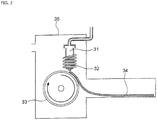
- FIG. 2 is a schematic view of an apparatus used for a normally employed single roller method.
- a molten metal 32 is sprayed and supplied from a nozzle 31 against a roller 33 rotating in the arrow direction, and a ribbon 34 is manufactured in the rotating direction of the roller 33.
- a molten metal is preferably cooled rapidly by increasing a cooling rate, that the cooling rate is preferably increased by increasing a contact time between the molten metal and a roller and by increasing a temperature difference between the molten metal and the roller, and that the roller thereby preferably normally has a temperature of about 5 to 30°C.
- the present inventors can achieve a rapid cooling of the ribbon 24 even if the roller 23 has a high temperature of about 50 to 70°C by rotating the roller 23 in the opposite direction (see FIG. 1 ) to the normal direction so as to further increase a contact time between the roller 23 and the ribbon 24.
- the soft magnetic alloy with the composition according to First Embodiment has a high uniformity of the cooled ribbon 24 and has fewer crystal phases composed of crystals having a grain size of larger than 30 nm by increasing the temperature of the roller 23 and further increasing a contact time between the roller 23 and the ribbon 24 compared to prior arts.
- the thickness of the ribbon 24 to be obtained can be controlled by mainly controlling the rotating speed of the roller 23, but can also be controlled by, for example, controlling the distance between the nozzle 21 and the roller 23, the temperature of the molten metal, and the like.
- the ribbon 24 has any thickness.
- the ribbon 24 may have a thickness of 15 to 30 ⁇ m.
- the chamber 25 has any inner vapor pressure.
- the chamber 25 may have an inner vapor pressure of 11 hPa or less using an Ar gas whose dew point is adjusted.
- the chamber 25 has no lower limit for inner vapor pressure.
- the chamber 25 may have a vapor pressure of 1 hPa or less by being filled with an Ar gas whose dew point is adjusted or by being turned into a state close to vacuum.
- the ribbon 24 (soft magnetic alloy according to the present embodiment) contains an amorphous phase containing no crystals having a grain size of larger than 30 nm and has a nanohetero structure where initial fine crystals exist in the amorphous phase.
- Fe based nanocrystallines are easily deposited.
- any method such as a normal X-ray diffraction measurement, can be used for confirming whether the ribbon 24 contains crystals having a grain size of larger than 30 nm.
- the existence and average grain size of the above-mentioned initial fine crystals are observed by any method, and can be observed by, for example, obtaining a selected area electron diffraction image, a nano beam diffraction image, a bright field image, or a high resolution image using a transmission electron microscope with respect to a sample thinned by ion milling.
- a selected area electron diffraction image or a nano beam diffraction image with respect to diffraction pattern, a ring-shaped diffraction is formed in case of being amorphous, and diffraction spots due to crystal structure are formed in case of being non-amorphous.
- a bright field image or a high resolution image an existence and an average grain size of initial fine crystals can be confirmed by visual observation with a magnification of 1.00 ⁇ 10 5 to 3.00 ⁇ 10 5 .
- the roller has any temperature and rotating speed, and the chamber has any atmosphere.
- the roller has a temperature of 4 to 30°C for amorphization.
- the roller has a rotating speed of 25 to 30 m/sec. for obtaining initial fine crystals having an average grain size of 0.3 to 10 nm.
- the chamber preferably has an atmosphere air.
- a soft magnetic alloy having a structure of Fe based nanocrystallines (a soft magnetic alloy according to the third aspect of the present invention) by carrying out a heat treatment against a ribbon 24 composed of a soft magnetic alloy having a nanohetero structure (a soft magnetic alloy according to the first aspect of the present invention).
- the soft magnetic alloy according to the present embodiment is manufactured with any heat-treatment conditions.
- Favorable heat-treatment conditions differ depending on a composition of the soft magnetic alloy.
- a heat-treatment temperature is preferably about 450 to 650°C
- a heat-treatment time is preferably about 0.5 to 10 hours, but favorable heat-treatment temperature and heat-treatment time may be in a range deviated from the above ranges depending on the composition.
- the heat treatment is carried out in any atmosphere, such as an active atmosphere of air and an inert atmosphere of Ar gas.
- Any method such as observation using a transmission electron microscope, is employed for calculation of an average grain size of Fe based nanocrystallines contained in the soft magnetic alloy obtained by heat treatment.
- the crystal structure of bcc (body-centered cubic structure) is also confirmed by any method, such as X-ray diffraction measurement.
- a powder of the soft magnetic alloy according to the present embodiment is obtained by a water atomizing method or a gas atomizing method, for example.
- a gas atomizing method is explained.
- a molten alloy of 1200 to 1500°C is obtained similarly to the above-mentioned single roller method. Thereafter, the molten alloy is sprayed in a chamber, and a powder is prepared.
- the above-mentioned favorable nanohetero structure is obtained easily with a gas spray temperature of 50 to 200°C and a vapor pressure of 4 hPa or less in the chamber.
- a heat treatment is conducted at 400 to 600°C for 0.5 to 10 minutes. This makes it possible to promote diffusion of atoms while the powder is prevented from being coarse due to sintering of each grain, reach a thermodynamic equilibrium state for a short time, remove distortion and stress, and easily obtain a Fe based soft magnetic alloy having an average grain size of 10 to 50 nm.
- a soft magnetic alloy before heat treatment is composed of only amorphous phases. Even if the soft magnetic alloy before heat treatment is composed of only amorphous phases, contains no initial fine crystals, and has no nanohetero structure, a soft magnetic alloy having a Fe based nanocrystalline structure, namely, a soft magnetic alloy according to the third aspect of the present invention can be obtained by heat treatment.
- Fe based nanocrystallines are hard to be deposited by heat treatment, and the average grain size of the Fe based nanocrystallines is hard to be controlled. Thus, excellent characteristics are hard to be obtained compared to First Embodiment.
- the soft magnetic alloy according to the present embodiment includes a main component of (Fe (1-( ⁇ + ⁇ )) X1 ⁇ X2 ⁇ ) (1-(a+b+c+d+e)) M a B b P c Si d C e , in which X1 is one or more of Co and Ni, X2 is one or more of Al, Mn, Ag, Zn, Sn, As, Sb, Cu, Cr, Bi, N, O, and rare earth elements, M is one or more of Nb, Hf, Zr, Ta, Mo, W, and V, 0.020 ⁇ a ⁇ 0.14 is satisfied, 0.020 ⁇ b ⁇ 0.20 is satisfied, 0 ⁇ c ⁇ 0.040 is satisfied, 0 ⁇ d ⁇ 0.060 is satisfied, 0.0005 ⁇ e ⁇ 0.0050 is satisfied, ⁇ 0 is satisfied, ⁇ 0 is satisfied, and 0 ⁇ + ⁇ 0.50 is satisfied, wherein the soft magnetic alloy has a nanohetero structure where initial fine crystals exist in an amorphous phase.
- the above-mentioned soft magnetic alloy (a soft magnetic alloy according to the second aspect of the present invention) undergoes a heat treatment, Fe based nanocrystallines are easily deposited in the soft magnetic alloy.
- the above-mentioned soft magnetic alloy easily becomes a starting raw material of a soft magnetic alloy where Fe based nanocrystallines are deposited (a soft magnetic alloy according to the fourth aspect of the present invention).
- the initial fine crystals preferably have an average grain size of 0.3 to 10 nm.
- the soft magnetic alloy according to the fourth aspect of the present invention has the same main component as the soft magnetic alloy according to the second aspect and has a structure of Fe based nanocrystallines.
- the content P (c) satisfies 0 ⁇ c ⁇ 0.040.
- the content P (c) is preferably 0.010 ⁇ c ⁇ 0.040, more preferably 0.020 ⁇ c ⁇ 0.030.
- the soft magnetic alloy has an improved resistivity and a low coercivity.
- a high permeability ⁇ ' can be maintained to a higher frequency.
- the C content (e) satisfies 0.0005 ⁇ e ⁇ 0.0050.
- the C content (e) is preferably 0.0006 ⁇ e ⁇ 0.0045, more preferably 0.0020 ⁇ e ⁇ 0.0045.
- the soft magnetic alloy easily has an improved resistivity and particularly easily has a low coercivity, and a high permeability ⁇ ' can be maintained to a high frequency.
- saturation magnetic flux density is decreased.
- X2 is one or more of Al, Mn, Ag, Zn, Sn, As, Sb, Cu, Cr, Bi, N, O, and rare earth elements.
- X2 is one or more of Al, Mn, Ag, Zn, Sn, As, Sb, Cu, Cr, Bi, N, O, and rare earth elements.
- this soft magnetic alloy undergoes a heat treatment, it becomes easier to obtain a soft magnetic alloy having a structure of Fe based nanocrystallines (a soft magnetic alloy according to the fourth aspect of the present invention).
- a soft magnetic alloy before heat treatment is composed of only amorphous phases. Even if the soft magnetic alloy before heat treatment is composed of only amorphous phases, contains no initial fine crystals, and has no nanohetero structure, a soft magnetic alloy having a Fe based nanocrystalline structure, namely, a soft magnetic alloy according to the fourth aspect of the present invention can be obtained by heat treatment.
- Fe based nanocrystallines are hard to be deposited by heat treatment, and the average grain size of the Fe based nanocrystallines is hard to be obtained. Thus, excellent characteristics are hard to be obtained compared to Third Embodiment.
- a magnetic device, especially a magnetic core and an inductor, according to Fifth Embodiment is obtained from the soft magnetic alloy according to any of First Embodiment to Fourth Embodiment.
- a magnetic core and an inductor according to Fifth Embodiment are explained, but the following method is not the only one method for obtaining the magnetic core and the inductor from the soft magnetic alloy.
- the magnetic core is used for transformers, motors, and the like.
- a magnetic core from a ribbon-shaped soft magnetic alloy is obtained by winding or laminating the ribbon-shaped soft magnetic alloy.
- a magnetic core having further improved properties can be obtained.
- a magnetic core from a powder-shaped soft magnetic alloy is obtained by appropriately mixing the powder-shaped soft magnetic alloy with a binder and pressing this using a die.
- an oxidation treatment, an insulation coating, or the like is carried out against the surface of the powder before the mixture with the binder, resistivity is improved, and the magnetic core becomes more suitable for high-frequency regions.
- the pressing method is not limited.
- Examples of the pressing method include a pressing using a die and a mold pressing.
- Examples of the binder include a silicone resin.
- 100 mass% of the soft magnetic alloy powder is mixed with 1 to 5 mass% of a binder and compressively pressed using a die, and it is thereby possible to obtain a magnetic core having a space factor (powder filling rate) of 70% or more, a magnetic flux density of 0.45T or more at the time of applying a magnetic field of 1.6 ⁇ 10 4 A/m, and a resistivity of 1 ⁇ •cm or more.
- space factor space factor
- 100 mass% of the soft magnetic alloy powder is mixed with 1 to 3 mass% of a binder and compressively pressed using a die under a temperature condition that is equal to or higher than a softening point of the binder, and it is thereby possible to obtain a dust core having a space factor of 80% or more, a magnetic flux density of 0.9T or more at the time of applying a magnetic field of 1.6 ⁇ 10 4 A/m, and a resistivity of 0.1 ⁇ •cm or more. These properties are more excellent than those of normal dust cores.
- a green compact constituting the above-mentioned magnetic core undergoes a heat treatment after the pressing for distortion removal. This further reduces core loss and improves usefulness.
- core loss of the magnetic core is decreased by reduction in coercivity of a magnetic material constituting the magnetic core.
- An inductance product is obtained by winding a wire around the above-mentioned magnetic core.
- the wire is wound by any method, and the inductance product is manufactured by any method.
- a wire is wound around a magnetic core manufactured by the above-mentioned method at least in one or more turns.
- an inductance product when using soft magnetic alloy grains, can be obtained by carrying out firing after alternately printing and laminating a soft magnetic alloy paste obtained by pasting the soft magnetic alloy grains added with a binder and a solvent and a conductor paste obtained by pasting a conductor metal for coils added with a binder and a solvent.
- an inductance product where a coil is incorporated into a magnetic material can be obtained by preparing a soft magnetic alloy sheet using a soft magnetic alloy paste, printing a conductor paste on the surface of the soft magnetic alloy sheet, and laminating and firing them.
- an inductance product is manufactured using soft magnetic alloy grains, in view of obtaining excellent Q properties, it is preferred to use a soft magnetic alloy powder whose maximum grain size is 45 ⁇ m or less by sieve diameter and center grain size (D50) is 30 ⁇ m or less.
- D50 center grain size
- a soft magnetic alloy powder that passes through a sieve whose mesh size is 45 ⁇ m may be used.
- Q values in high-frequency regions may decrease greatly.
- a soft magnetic alloy powder having a large variation can be used.
- cost can be reduced as it can be manufactured comparatively inexpensively.
- the soft magnetic alloy has any shape.
- the soft magnetic alloy has a ribbon shape or a powder shape as mentioned above, but may have another shape of block etc.
- the soft magnetic alloys (Fe based nanocrystalline alloys) according to First Embodiment to Fourth Embodiment are used for any purposes, such as magnetic devices (particularly magnetic cores), and can favorably be used as magnetic cores for inductors (particularly for power inductors).
- the soft magnetic alloys according to the embodiments can favorably be used for thin film inductors and magnetic heads.
- Raw material metals were weighed so that the alloy compositions of Examples and Comparative Examples shown in the following table would be obtained, and the weighed raw material metals were melted by high-frequency heating. Then, base alloys were manufactured. Incidentally, the compositions of Sample No. 9 and Sample No. 10 were a composition of a normally well-known amorphous alloy.
- the manufactured base alloys were thereafter heated, melted, and turned into a molten metal at 1250°C.
- This metal was sprayed against a roller rotating at 25 m/sec. (single roller method), and ribbons were thereby obtained.
- the roller was made of Cu.
- Example No. 1 to Sample No. 4 the roller was rotated in the direction shown in FIG. 2 , and the roller temperature was 30°C.
- the roller rotating speed was controlled, and the ribbons to be obtained thereby had a thickness of 20 ⁇ m to 30 ⁇ m, a width of 4 mm to 5 mm, and a length of several tens of meter.
- the roller was rotated in the direction shown in FIG. 1 , and the roller temperature was 70°C.
- the ribbon to be obtained had a thickness of 20 ⁇ m to 30 ⁇ m, a width of 4 mm to 5 mm, and a length of several tens of meter, provided that the differential pressure between the inside of the chamber and the inside of the spray nozzle was 105 kPa, that the nozzle diameter was 5 mm slit, that the flow rate was 50 g, and that the roller diameter ⁇ was 300 mm.
- the roller was rotated in the direction shown in FIG. 1 , and the roller temperature was 30°C.
- the ribbon to be obtained had a thickness of 20 ⁇ m to 30 ⁇ m, a width of 4 mm to 5 mm, and a length of several tens of meter, provided that the differential pressure between the inside of the chamber and the inside of the spray nozzle was 105 kPa, that the nozzle diameter was 5 mm slit, that the flow rate was 50 g, and that the roller diameter ⁇ was 300 mm.
- each of the obtained ribbons underwent an X-ray diffraction measurement and was confirmed if it contained crystals having a grain size of larger than 30 nm.
- the ribbon When crystals having a grain size of larger than 30 nm did not exist, the ribbon was considered to be composed of amorphous phases.
- the ribbon When crystals having a grain size of larger than 30 nm existed, the ribbon was considered to be composed of crystalline phases.
- all of Examples except for Sample No. 135 mentioned below had a nanohetero structure where initial fine crystals existed in amorphous phases.
- each ribbon of Examples and Comparative Examples underwent a heat treatment with the conditions shown in the following table.
- Each ribbon after the heat treatment was measured for resistivity, saturation magnetic flux density, coercivity, and permeability ⁇ '.
- the resistivity (p) was measured by four probe method.
- the saturation magnetic flux density (Bs) was measured in a magnetic field of 1000 kA/m using a vibrating sample type magnetometer (VSM).
- the coercivity (Hc) was measured in a magnetic field of 5 kA/m using a DC BH tracer.
- the permeability ⁇ ' was measured by changing frequency using an impedance analyzer and was evaluated as a frequency when the permeability ⁇ ' became 10000 (hereinafter, also referred to as a specific frequency f).
- a resistivity of 110 ⁇ cm or more was represented by ⁇
- a resistivity of 100 ⁇ cm or more and less than 110 ⁇ cm was represented by ⁇
- a resistivity of less than 100 ⁇ cm was ⁇ .
- the evaluation was higher in the order of ⁇ , ⁇ , and ⁇ .
- the evaluation of ⁇ and ⁇ was considered to be good.
- a saturation magnetic flux density of 1.35T or more was considered to be good, and a saturation magnetic flux density of 1.40T or more was considered to be better.
- Table 1 shows that all characteristics were good in Sample No. 7 and Sample No. 8 (each component content was in a predetermined range, and the roller contact distance and the roller temperature were controlled favorably). On the other hand, Table 1 shows that any of characteristics was bad in Sample No. 1, Sample No. 2, Sample No. 5, Sample No. 6, Sample No. 9, and Sample No. 10 (each component content, especially P content, was outside a predetermined range). Table 1 also shows that the ribbon before the heat treatment was composed of crystalline phases and had a small resistivity, a significantly large coercivity, a significantly small permeability ⁇ ', and no specific frequency f after the heat treatment in Sample No. 3, Sample No. 4, Sample No. 7a, and Sample No. 8a (each component content was in a predetermined range, but the roller contact distance and/or the roller temperature was/were not controlled favorably).
- Experimental Example 2 was carried out with the same conditions as Sample No. 5 to Sample No. 10 of Experimental Example 1 except that base alloys were manufactured by weighing raw material metals so that alloy compositions of Examples and Comparative Examples shown in the following tables would be obtained and by melting the raw material metals with high-frequency heating.
- Nb 0,120 amorphous phase ⁇ 2,7 1,42 140 71
- Hf 0,120 amorphous phase ⁇ 2,6 1,41 140 72
- Zr 0,120 amorphous phase ⁇ 2,7 1,43 120 72
- Ta 73
- Ta 73
- Ta 73
- Ta 73
- Ta 73
- Ta 73
- Mo Ex.
- Mo 0,120 amorphous phase ⁇ 2,5 1,40 120
- W 0,120 amorphous phase ⁇ 2,6 1,40 120
- V 0,120 amorphous phase ⁇ 2,8 1,41 100
- Nb0.5Hf0.5 0,120 amorphous phase ⁇ 2,6 1,42 110 78
- Table 2 shows examples whose M content (a), B content (b), P content (c), Si content (d), and C content (e) were changed.
- the type of M was Nb.
- Examples whose each component content was in a predetermined range had a good resistivity ⁇ , a good saturation magnetic flux density Bs, a good coercivity Hc, and a good permeability ⁇ '.
- Sample No. 29 (P content (c) was too small) had a small resistivity ⁇ , a large coercivity Hc, a small permeability ⁇ ', and a small specific frequency f after the heat treatment.
- Sample No. 36 (P content (c) was too large) had a low saturation magnetic flux density Bs.
- Sample No. 47 Si content (d) was too large had a large coercivity Hc after the heat treatment.
- Sample No. 41 C content (e) was too large) had a small resistivity ⁇ , a large coercivity Hc, a small permeability ⁇ ', and a small specific frequency f after the heat treatment.
- Table 3 shows Examples whose M type was changed in Sample No. 11, Sample No. 14, and Sample No. 18.
- Sample No. 53 to 61 were Examples whose M type was changed in Sample No. 14.
- Sample No. 62 to 70 were Examples whose M type was changed in Sample No. 11.
- Sample No. 71 to 79 were Examples whose M type was changed in Sample No. 18.
- Table 3 shows that excellent characteristics were exhibited even if the type of M was changed.
- Table 4 shows Examples where a part of Fe was substituted by X1 and/or X2 in Sample No. 11.
- Table 4 shows that excellent characteristics were exhibited even if a part of Fe was substituted by X1 and/or X2.
- Table 5 shows that when the initial fine crystals had an average grain size of 0.3 to 10 nm and when the Fe based nanocrystalline alloy had an average grain size of 5 to 30 nm, both saturation magnetic flux density Bs and coercivity Hc were good compared to those when these ranges were not satisfied.
- the manufactured base alloys were thereafter heated, melted, and turned into a molten metal at 1250°C.
- This molten metal was sprayed against a roller rotating at 25 m/sec. (single roller method), and ribbons were thereby obtained.
- the roller was made of Cu.
- the roller was rotated in the direction shown in FIG. 2 , and the roller temperature was 30°C.
- the roller rotating speed was controlled, and the ribbon to be obtained thereby had a thickness of 20 ⁇ m to 30 ⁇ m, a width of 4 mm to 5 mm, and a length of several tens of meter.
- the roller was rotated in the direction shown in FIG. 1 , and the roller temperature was 70°C.
- the ribbon to be obtained had a thickness of about 20 ⁇ m to 30 ⁇ m, a width of 4 mm to 5 mm, and a length of several tens of meter, provided that the differential pressure between the inside of the chamber and the inside of the spray nozzle was 105 kPa, that the nozzle diameter was 5 mm slit, that the flow rate was 50g, and that the roller diameter ⁇ was 300 mm.
- each of the obtained ribbons underwent an X-ray diffraction measurement and was confirmed if it contained crystals having a grain size of larger than 30 nm.
- the ribbon When crystals having a grain size of larger than 30 nm did not exist, the ribbon was considered to be composed of amorphous phases.
- the ribbon When crystals having a grain size of larger than 30 nm existed, the ribbon was considered to be composed of crystalline phases.
- all of Examples except for Sample No. 274 mentioned below had a nanohetero structure where initial fine crystals existed in amorphous phases.
- the ribbons of Examples and Comparative Examples underwent a heat treatment with the conditions shown in the following table.
- Each of the ribbons after the heat treatment was measured for resistivity, saturation magnetic flux density, coercivity, and permeability ⁇ '.
- the resistivity (p) was measured by four probe method.
- the saturation magnetic flux density (Bs) was measured in a magnetic field of 1000 kA/m using a vibrating sample type magnetometer (VSM).
- the coercivity (Hc) was measured in a magnetic field of 5 kA/m using a DC BH tracer.
- the permeability ⁇ ' was measured by changing frequency using an impedance analyzer and was evaluated as a frequency when the permeability ⁇ ' became 10000 (hereinafter, also referred to as a specific frequency f).
- a resistivity of 100 ⁇ cm or more was represented by ⁇
- a resistivity of 80 ⁇ cm or more and less than 100 ⁇ cm was represented by ⁇
- a resistivity of less than 80 ⁇ cm was ⁇ .
- the evaluation was higher in the order of ⁇ , ⁇ , and ⁇ .
- the evaluation of ⁇ and ⁇ was considered to be good.
- a saturation magnetic flux density of 1.50T or more was considered to be good.
- a coercivity of 4.0 A/m or less was considered to be good.
- the permeability ⁇ ' was considered to be good when a specific frequency f was 70 kHz or more.
- Table 6 shows that all characterstics were good in Sample No. 206 (each component content was in a predetermined range, and the roller contact distance and the roller temperature were controlled favorably). On the other hand, Table 6 shows that any of characteristics was bad in Sample No. 201 to Sample No. 205 and Sample No. 207 to Sample No. 209 (each component content, especially P content and/or C content, was outside a predetermined range).
- Experimental Example 5 was carried out with the same conditions as Sample No. 206 of Experimental Example 4 except that base alloys were manufactured by weighing raw material metals so that alloy compositions of Examples and Comparative Examples shown in the following tables would be obtained and by melting the raw material metals with high-frequency heating.
- Table 7 shows Examples whose M content (a), B content (b), P content (c), Si content (d), and C content (e) were changed. Incidentally, the type of M Nb. Examples whose each component content was in a predetermined range had a good resistivity p, a good saturation magnetic flux density Bs, a good coercivity Hc, and a good permeability ⁇ '.
- Sample No. 211 M content (a) was too small
- the ribbon before the heat treatment was composed of crystalline phases and had a small resistivity p, a significantly large coercivity Hc, a significantly small permeability ⁇ ', and no specific frequency f after the heat treatment.
- Sample No. 220 M content (a) was too large) had a low saturation magnetic flux density Bs.
- Table 8 shows Examples whose M type in Sample No. 206 was changed.
- Table 8 shows that excellent characteristics were exhibited even if the type of M was changed.
- Table 9 shows Examples where a part of Fe in Sample No. 206 was substituted by X1 and/or X2.
- Table 9 shows that excellent characteristics were exhibited even if a part of Fe was substituted by X1 and/or X2.
- Table 10 shows that a soft magnetic alloy containing no crystalline phases composed of crystals having a grain size of larger than 30 nm was obtained in each sample of Table 9 even if the ribbon to be obtained had a thickness of about 40 ⁇ m to 50 ⁇ m.
- Table 11 shows that when the initial fine crystals had an average grain size of 0.3 to 10 nm and when the Fe based nanocrystalline alloy had an average grain size of 5 to 30 nm, both saturation magnetic flux density Bs and coercivity Hc were good compared to those when these ranges were not satisfied.
Landscapes
- Engineering & Computer Science (AREA)
- Chemical & Material Sciences (AREA)
- Power Engineering (AREA)
- Materials Engineering (AREA)
- Mechanical Engineering (AREA)
- Organic Chemistry (AREA)
- Metallurgy (AREA)
- Physics & Mathematics (AREA)
- Electromagnetism (AREA)
- Dispersion Chemistry (AREA)
- Manufacturing & Machinery (AREA)
- Crystallography & Structural Chemistry (AREA)
- Inorganic Chemistry (AREA)
- Soft Magnetic Materials (AREA)
- Hard Magnetic Materials (AREA)
Abstract
Description
- The present invention relates to a soft magnetic alloy and a magnetic device.
- Low power consumption and high efficiency have been demanded in electronic, information, communication equipment, and the like. Moreover, the above demands are becoming stronger for a low carbon society. Thus, reduction in energy loss and improvement in power supply efficiency are also required for power supply circuits of electronic, information, communication equipment, and the like. Then, improvement in saturation magnetic flux density and permeability and reduction in core loss (magnetic core loss) are required for the magnetic core of the magnetic element used in the power supply circuit. The reduction in core loss reduces the loss of power energy, and the improvement in permeability downsizes a magnetic element. Thus, high efficiency and energy saving are achieved.
- Patent Document 1 discloses a Fe-B-M based soft magnetic amorphous alloy (M = Ti, Zr, Hf, V, Nb, Ta, Mo, and W). This soft magnetic amorphous alloy has favorable soft magnetic properties, such as a high saturation magnetic flux density, compared to a saturation magnetic flux density of a commercially available Fe based amorphous material.
- Patent Document 1:
JP3342767 (B2 - As a method of reducing the core loss of the magnetic core, it is conceivable to reduce coercivity of a magnetic material constituting the magnetic core.
- Patent Document 1 discloses that soft magnetic characteristics can be improved by depositing fine crystal phases in the Fe based soft magnetic alloy. At present, however, required is a soft magnetic alloy having high soft magnetic characteristics and being capable of maintaining a high permeability to a higher frequency.
- It is an object of the invention to provide a soft magnetic alloy having high resistivity and saturation magnetic flux density and a low coercivity and being capable of maintaining a high permeability to a higher frequency.
- To achieve the above object, a soft magnetic alloy according to the first aspect of the present invention includes a main component of (Fe(1-(α+β))X1αX2β)(i-(a+b+c+d+e))MaBbPcSidCe, in which
X1 is one or more of Co and Ni,
X2 is one or more of Al, Mn, Ag, Zn, Sn, As, Sb, Cu, Cr, Bi, N, O, and rare earth elements,
M is one or more of Nb, Hf, Zr, Ta, Mo, W, and V,
0.020≤a≤0.14 is satisfied,
0.020≤b≤0.20 is satisfied,
0.040≤c≤0.15 is satisfied,
0≤d≤0.060 is satisfied,
0≤e≤0.030 is satisfied,
α≥ 0 is satisfied,
β≥ 0 is satisfied, and
0≤α+β≤0.50 is satisfied,
wherein the soft magnetic alloy has a nanohetero structure where initial fine crystals exist in an amorphous phase. - To achieve the above object, a soft magnetic alloy according to the second aspect of the present invention includes a main component of (Fe(1-(α+β))X1αX2β)(1-(a+b+c+d+e))MaBbPcSidCe, in which
X1 is one or more of Co and Ni,
X2 is one or more of A1, Mn, Ag, Zn, Sn, As, Sb, Cu, Cr, Bi, N, O, and rare earth elements,
M is one or more of Nb, Hf, Zr, Ta, Mo, W, and V,
0.020≤a≤0.14 is satisfied,
0.020≤b≤0.20 is satisfied,
0<c≤0.040 is satisfied,
0≤d≤0.060 is satisfied,
0.0005<e<0.0050 is satisfied,
α≥ 0 is satisfied,
β≥ 0 is satisfied, and
0≤α+β≤0.50 is satisfied,
wherein the soft magnetic alloy has a nanohetero structure where initial fine crystals exist in an amorphous phase. - In the soft magnetic alloy according to the first and second aspects of the present invention, the initial fine crystals may have an average grain size of 0.3 to 10 nm.
- To achieve the above object, a soft magnetic alloy according to the third aspect of the present invention includes a main component of (Fe(1-(α+β))X1αX2β)(1-(a+b+c+d+e))MaBbPcSidCe, in which
X1 is one or more of Co and Ni,
X2 is one or more of Al, Mn, Ag, Zn, Sn, As, Sb, Cu, Cr, Bi, N, O, and rare earth elements,
M is one or more of Nb, Hf, Zr, Ta, Mo, W, and V,
0.020≤a≤0.14 is satisfied,
0.020≤b≤0.20 is satisfied,
0.040≤c≤0.15 is satisfied,
0≤d≤0.060 is satisfied,
0≤e≤0.030 is satisfied,
α≥ 0 is satisfied,
β≥ 0 is satisfied, and
0≤α+β≤0.5 is satisfied,
wherein the soft magnetic alloy has a structure of Fe based nanocrystallines. - To achieve the above object, a soft magnetic alloy according to the fourth aspect of the present invention includes a main component of (Fe(1-(α+β))X1αX2β)(1-(a+b+c+d+e))MaBbPcSidCe, in which
X1 is one or more of Co and Ni,
X2 is one or more of Al, Mn, Ag, Zn, Sn, As, Sb, Cu, Cr, Bi, N, O, and rare earth elements,
M is one or more of Nb, Hf, Zr, Ta, Mo, W, and V,
0.020≤a≤0.14 is satisfied,
0.020≤b≤0.20 is satisfied,
0<c≤0.040 is satisfied,
0≤d≤0.060 is satisfied,
0.0005<e<0.0050 is satisfied,
α≥ 0 is satisfied,
β≥ 0 is satisfied, and
0≤α+β≤0.50 is satisfied,
wherein the soft magnetic alloy has a structure of Fe based nanocrystallines. - In the soft magnetic alloy according to the third and fourth aspects of the present invention, the Fe based nanocrystallines may have an average grain size of 5 to 30 nm.
- Since the soft magnetic alloy according to the first aspect of the present invention has the above features, the soft magnetic alloy according to the third aspect of the present invention is easily obtained by heat treatment. Since the soft magnetic alloy according to the second aspect of the present invention has the above features, the soft magnetic alloy according to the fourth aspect of the present invention is easily obtained by heat treatment. In the soft magnetic alloy according to the third aspect and the soft magnetic alloy according to the fourth aspect, a high resistivity, a high saturation magnetic flux density, and a low coercivity can be achieved at the same time, and a higher permeability µ' can be maintained to a higher frequency. Incidentally, µ' is a real part of a complex permeability.
- The following description regarding the soft magnetic alloys according to the present invention is common among the first to fourth aspects.
- In the soft magnetic alloys according to the present invention, 0.73≤1-(a+b+c+d+e)≤0.95 may be satisfied.
- In the soft magnetic alloys according to the present invention, 0≤a{1-(a+b+c+d+e)}≤0.40 may be satisfied.
- In the soft magnetic alloys according to the present invention, α=0 may be satisfied.
- In the soft magnetic alloys according to the present invention, 0≤β{1-(a+b+c+d+e)}≤0.030 may be satisfied.
- In the soft magnetic alloys according to the present invention, β=0 may be satisfied.
- In the soft magnetic alloys according to the present invention, α=β=0 may be satisfied.
- The soft magnetic alloys according to the present invention may have a ribbon shape.
- The soft magnetic alloys according to the present invention may have a powder shape.
- A magnetic device according to the present invention contains the above-mentioned soft magnetic alloy.
-
-
FIG. 1 is a schematic view of a single roller method. -
FIG. 2 is a schematic view of a single roller method. - Hereinafter, First Embodiment to Fifth Embodiment of the present invention are explained.
- A soft magnetic alloy according to the present embodiment includes a main component of (Fe(1-(α+β))X1αX2β)(1-(a+b+c+d+e))MaBbPcSidCe, in which
X1 is one or more of Co and Ni,
X2 is one or more of Al, Mn, Ag, Zn, Sn, As, Sb, Cu, Cr, Bi, N, O, and rare earth elements,
M is one or more of Nb, Hf, Zr, Ta, Mo, W, and V,
0.020≤a≤0.14 is satisfied,
0.020≤b≤0.20 is satisfied,
0.040≤c≤0.15 is satisfied,
0≤d≤0.060 is satisfied,
0≤e≤0.030 is satisfied,
α≥ 0 is satisfied,
β≥ 0 is satisfied, and
0≤α+β≤0.50 is satisfied,
wherein the soft magnetic alloy has a nanohetero structure where initial fine crystals exist in an amorphous phase. - When the above-mentioned soft magnetic alloy (a soft magnetic alloy according to the first aspect of the present invention) undergoes a heat treatment, Fe based nanocrystallines are easily deposited in the soft magnetic alloy. In other words, the above-mentioned soft magnetic alloy easily becomes a starting raw material of a soft magnetic alloy where Fe based nanocrystallines are deposited (a soft magnetic alloy according to the third aspect of the present invention). Incidentally, the initial fine crystals preferably have an average grain size of 0.3 to 10 nm.
- The soft magnetic alloy according to the third aspect of the present invention includes the same main component as the soft magnetic alloy according to the first aspect and a structure of Fe based nanocrystallines.
- The Fe based nanocrystallines are crystals whose grain size is nano-order and whose crystal structure of Fe is bcc (body-centered cubic). In the present embodiment, it is preferable to deposit Fe based nanocrystallines having an average grain size of 5 to 30 nm. The soft magnetic alloy where Fe based nanocrystallines are deposited is easy to have a high saturation magnetic flux density and a low coercivity.
- Hereinafter, each component of the soft magnetic alloy according to the present embodiment is explained in detail.
- M is one or more of Nb, Hf, Zr, Ta, Mo, W, and V.
- The M content (a) satisfies 0.020≤a≤0.14. The M content (a) is preferably 0.040≤a≤0.10, more preferably 0.050≤a≤0.080. When the M content (a) is small, a crystal phase composed of crystals having a grain size of larger than 30 nm is easily generated in the soft magnetic alloy. When the crystal phase is generated, Fe based nanocrystallines cannot be deposited by heat treatment, and the soft magnetic alloy easily has a low resistivity, a high coercivity, and a low permeability µ'. When the M content (a) is large, the soft magnetic alloy easily has a low saturation magnetic flux density.
- The B content (b) satisfies 0.020<b≤0.20. The B content (b) may be 0.025≤b≤0.20 and is preferably 0.060≤b≤0.15, more preferably 0.080≤b≤0.12. When the B content (b) is small, a crystal phase composed of crystals having a grain size of larger than 30 nm is easily generated in the soft magnetic alloy. When the crystal phase is generated, Fe based nanocrystallines cannot be deposited by heat treatment, and the soft magnetic alloy easily has a low resistivity, a high coercivity, and a low permeability µ'. When the B content (b) is large, the soft magnetic alloy easily has a low saturation magnetic flux density.
- The P content (c) satisfies 0.040<c≤0.15. The P content (c) may be 0.041≤c≤0.15 and is preferably 0.045<c<0.10, more preferably 0.050≤c≤0.070. When the P content (c) is in the above range, especially in the range of c>0.040, the soft magnetic alloy has an improved resistivity and a low coercivity. Moreover, when the soft magnetic alloy has an improved resistivity, a high permeability µ' can be maintained to a higher frequency. When the P content (c) is small, the above effects are hard to be obtained. When the P content (c) is large, the soft magnetic alloy easily has a low saturation magnetic flux density.
- The Si content (d) satisfies 0≤d≤0.060. That is, Si may not be contained. The Si content (d) is preferably 0.005≤d≤0.030, more preferably 0.010≤d≤0.020. When the soft magnetic alloy contains Si, resistivity is particularly easily improved, and coercivity is easily decreased. Moreover, when the soft magnetic alloy has an improved resistivity, a high permeability µ' can be maintained to a high frequency. When the Si content (d) is large, the soft magnetic alloy has an increased coercivity on the contrary.
- The C content (e) satisfies 0≤e≤0.030. That is, C may not be contained. The C content (e) is preferably 0.001≤e≤0.010, more preferably 0.001≤e≤0.005. When the soft magnetic alloy contains C, coercivity is particularly easily decreased, and coercivity is easily decreased. When the C content (e) is large, the soft magnetic alloy has a low resistivity and has an increased coercivity on the contrary, and a high permeability µ' is hard to be maintained to a high frequency.
- The Fe content (1-(a+b+c+d+e)) is not limited, but is preferably 0.73≤(1-(a+b+c+d+e))≤0.95. When the Fe content (1-(a+b+c+d+e)) is in the above range, a crystal phase composed of crystals having a grain size of larger than 30 nm is hard to be generated, and it thereby becomes easy to obtain a soft magnetic alloy where Fe based nanocrystallines are deposited.
- In the soft magnetic alloy according to the present embodiment, a part of Fe may be substituted by X1 and/or X2.
- X1 is one or more of Co and Ni. The X1 content may be α=0. That is, X1 may not be contained. Preferably, the number of atoms of X1 is 40 at% or less if the number of atoms of the entire composition is 100 at%. That is, 0≤α{1-(a+b+c+d+e)}<0.40 is preferably satisfied.
- X2 is one or more of Al, Mn, Ag, Zn, Sn, As, Sb, Cu, Cr, Bi, N, O, and rare earth elements. The content X2 may be β=0. That is, X2 may not be contained. Preferably, the number of atoms of X2 is 3.0 at% or less if the number of atoms of the entire composition is 100 at%. That is, 0≤β{1-(a+b+c+d+e)}≤0.030 is preferably satisfied.
- The substitution amount of Fe by X1 and/or X2 is half or less of Fe based on the number of atoms. That is, 0≤α+β≤0.50 is satisfied. When α+β>0.50 is satisfied, the soft magnetic alloy according to the third aspect of the present invention is hard to be obtained by heat treatment.
- Incidentally, the soft magnetic alloys of the present embodiment may contain elements other than the above-mentioned elements as unavoidable impurities. For example, 0.1 wt% or less of unavoidable impurities may be contained with respect to 100 wt% of the soft magnetic alloy.
- Hereinafter, a method of manufacturing the soft magnetic alloy is explained.
- The soft magnetic alloy is manufactured by any method. For example, a ribbon of the soft magnetic alloy is manufactured by a single roller method. The ribbon may be a continuous ribbon.
- In the single roller method, pure metals of respective metal elements contained in a soft magnetic alloy finally obtained are initially prepared and weighed so that a composition identical to that of the soft magnetic alloy finally obtained is obtained. Then, the pure metal of each metal element is melted and mixed, and a base alloy is prepared. Incidentally, the pure metals are melted by any method. For example, the pure metals are melted by high-frequency heating after a chamber is evacuated. Incidentally, the base alloy and the soft magnetic alloy finally obtained normally have the same composition.
- Next, the prepared base alloy is heated and melted, and a molten metal is obtained. The molten metal has any temperature, and may have a temperature of 1200 to 1500°C, for example.
-
FIG. 1 is a schematic view of an apparatus used for a single roller method according to the present embodiment. In the single roller method according to the present embodiment, amolten metal 22 is sprayed and supplied from anozzle 21 against aroller 23 rotating in the arrow direction, and aribbon 24 is thereby manufactured in the rotating direction of theroller 23 in achamber 25. Incidentally, theroller 23 is made by any material, such as Cu, in the present embodiment. - On the other hand,
FIG. 2 is a schematic view of an apparatus used for a normally employed single roller method. In achamber 35, amolten metal 32 is sprayed and supplied from anozzle 31 against aroller 33 rotating in the arrow direction, and aribbon 34 is manufactured in the rotating direction of theroller 33. - In the single roller method, it is conventionally considered that a molten metal is preferably cooled rapidly by increasing a cooling rate, that the cooling rate is preferably increased by increasing a contact time between the molten metal and a roller and by increasing a temperature difference between the molten metal and the roller, and that the roller thereby preferably normally has a temperature of about 5 to 30°C.
- The present inventors can achieve a rapid cooling of the
ribbon 24 even if theroller 23 has a high temperature of about 50 to 70°C by rotating theroller 23 in the opposite direction (seeFIG. 1 ) to the normal direction so as to further increase a contact time between theroller 23 and theribbon 24. The soft magnetic alloy with the composition according to First Embodiment has a high uniformity of the cooledribbon 24 and has fewer crystal phases composed of crystals having a grain size of larger than 30 nm by increasing the temperature of theroller 23 and further increasing a contact time between theroller 23 and theribbon 24 compared to prior arts. In spite of a composition where crystals having a grain size of larger than 30 nm are generated in a conventional method, it is consequently possible to obtain a soft magnetic alloy containing no crystal phases composed of crystals having a grain size of larger than 30 nm. Incidentally, when the roller has a normal temperature of 5 to 30°C while being rotated in the opposite direction (seeFIG. 1 ) to the normal direction, theribbon 24 is easily peeled from theroller 23, and the effect of the opposite rotation cannot be obtained. - In the single roller method, the thickness of the
ribbon 24 to be obtained can be controlled by mainly controlling the rotating speed of theroller 23, but can also be controlled by, for example, controlling the distance between thenozzle 21 and theroller 23, the temperature of the molten metal, and the like. Theribbon 24 has any thickness. For example, theribbon 24 may have a thickness of 15 to 30 µm. - The
chamber 25 has any inner vapor pressure. For example, thechamber 25 may have an inner vapor pressure of 11 hPa or less using an Ar gas whose dew point is adjusted. Incidentally, thechamber 25 has no lower limit for inner vapor pressure. Thechamber 25 may have a vapor pressure of 1 hPa or less by being filled with an Ar gas whose dew point is adjusted or by being turned into a state close to vacuum. - The ribbon 24 (soft magnetic alloy according to the present embodiment) contains an amorphous phase containing no crystals having a grain size of larger than 30 nm and has a nanohetero structure where initial fine crystals exist in the amorphous phase. When the soft magnetic alloy undergoes the following heat treatment, Fe based nanocrystallines are easily deposited.
- Incidentally, any method, such as a normal X-ray diffraction measurement, can be used for confirming whether the
ribbon 24 contains crystals having a grain size of larger than 30 nm. - The existence and average grain size of the above-mentioned initial fine crystals are observed by any method, and can be observed by, for example, obtaining a selected area electron diffraction image, a nano beam diffraction image, a bright field image, or a high resolution image using a transmission electron microscope with respect to a sample thinned by ion milling. When using a selected area electron diffraction image or a nano beam diffraction image, with respect to diffraction pattern, a ring-shaped diffraction is formed in case of being amorphous, and diffraction spots due to crystal structure are formed in case of being non-amorphous. When using a bright field image or a high resolution image, an existence and an average grain size of initial fine crystals can be confirmed by visual observation with a magnification of 1.00 × 10⁵ to 3.00 × 10⁵.
- The roller has any temperature and rotating speed, and the chamber has any atmosphere. Preferably, the roller has a temperature of 4 to 30°C for amorphization. The faster a rotating speed of the roller is, the smaller an average grain size of initial fine crystals is. Preferably, the roller has a rotating speed of 25 to 30 m/sec. for obtaining initial fine crystals having an average grain size of 0.3 to 10 nm. In view of cost, the chamber preferably has an atmosphere air.
- Hereinafter, explained is a method of manufacturing a soft magnetic alloy having a structure of Fe based nanocrystallines (a soft magnetic alloy according to the third aspect of the present invention) by carrying out a heat treatment against a
ribbon 24 composed of a soft magnetic alloy having a nanohetero structure (a soft magnetic alloy according to the first aspect of the present invention). - The soft magnetic alloy according to the present embodiment is manufactured with any heat-treatment conditions. Favorable heat-treatment conditions differ depending on a composition of the soft magnetic alloy. Normally, a heat-treatment temperature is preferably about 450 to 650°C, and a heat-treatment time is preferably about 0.5 to 10 hours, but favorable heat-treatment temperature and heat-treatment time may be in a range deviated from the above ranges depending on the composition. The heat treatment is carried out in any atmosphere, such as an active atmosphere of air and an inert atmosphere of Ar gas.
- Any method, such as observation using a transmission electron microscope, is employed for calculation of an average grain size of Fe based nanocrystallines contained in the soft magnetic alloy obtained by heat treatment. The crystal structure of bcc (body-centered cubic structure) is also confirmed by any method, such as X-ray diffraction measurement.
- In addition to the above-mentioned single roller method, a powder of the soft magnetic alloy according to the present embodiment is obtained by a water atomizing method or a gas atomizing method, for example. Hereinafter, a gas atomizing method is explained.
- In a gas atomizing method, a molten alloy of 1200 to 1500°C is obtained similarly to the above-mentioned single roller method. Thereafter, the molten alloy is sprayed in a chamber, and a powder is prepared.
- At this time, the above-mentioned favorable nanohetero structure is obtained easily with a gas spray temperature of 50 to 200°C and a vapor pressure of 4 hPa or less in the chamber.
- After the powder composed of the soft magnetic alloy having the nanohetero structure is prepared by the gas atomizing method, a heat treatment is conducted at 400 to 600°C for 0.5 to 10 minutes. This makes it possible to promote diffusion of atoms while the powder is prevented from being coarse due to sintering of each grain, reach a thermodynamic equilibrium state for a short time, remove distortion and stress, and easily obtain a Fe based soft magnetic alloy having an average grain size of 10 to 50 nm.
- Hereinafter, Second Embodiment of the present invention is explained. The same matters as First Embodiment are not explained.
- In Second Embodiment, a soft magnetic alloy before heat treatment is composed of only amorphous phases. Even if the soft magnetic alloy before heat treatment is composed of only amorphous phases, contains no initial fine crystals, and has no nanohetero structure, a soft magnetic alloy having a Fe based nanocrystalline structure, namely, a soft magnetic alloy according to the third aspect of the present invention can be obtained by heat treatment.
- Compared to First Embodiment, however, Fe based nanocrystallines are hard to be deposited by heat treatment, and the average grain size of the Fe based nanocrystallines is hard to be controlled. Thus, excellent characteristics are hard to be obtained compared to First Embodiment.
- Hereinafter, Third Embodiment of the present invention is explained. The same matters as First Embodiment are not explained.
- The soft magnetic alloy according to the present embodiment includes a main component of (Fe(1-(α+β))X1αX2β)(1-(a+b+c+d+e))MaBbPcSidCe, in which
X1 is one or more of Co and Ni,
X2 is one or more of Al, Mn, Ag, Zn, Sn, As, Sb, Cu, Cr, Bi, N, O, and rare earth elements,
M is one or more of Nb, Hf, Zr, Ta, Mo, W, and V,
0.020≤a≤0.14 is satisfied,
0.020≤b≤0.20 is satisfied,
0<c≤0.040 is satisfied,
0≤d≤0.060 is satisfied,
0.0005<e<0.0050 is satisfied,
α≥ 0 is satisfied,
β≥ 0 is satisfied, and
0≤α+β≤0.50 is satisfied,
wherein the soft magnetic alloy has a nanohetero structure where initial fine crystals exist in an amorphous phase. - When the above-mentioned soft magnetic alloy (a soft magnetic alloy according to the second aspect of the present invention) undergoes a heat treatment, Fe based nanocrystallines are easily deposited in the soft magnetic alloy. In other words, the above-mentioned soft magnetic alloy easily becomes a starting raw material of a soft magnetic alloy where Fe based nanocrystallines are deposited (a soft magnetic alloy according to the fourth aspect of the present invention). Incidentally, the initial fine crystals preferably have an average grain size of 0.3 to 10 nm.
- The soft magnetic alloy according to the fourth aspect of the present invention has the same main component as the soft magnetic alloy according to the second aspect and has a structure of Fe based nanocrystallines.
- The content P (c) satisfies 0<c≤0.040. The content P (c) is preferably 0.010≤c≤0.040, more preferably 0.020≤c≤0.030. When the content P (c) is in the above range, the soft magnetic alloy has an improved resistivity and a low coercivity. Moreover, when the soft magnetic alloy has an improved resistivity, a high permeability µ' can be maintained to a higher frequency. When c=0 is satisfied, the above-mentioned effects cannot be obtained.
- The C content (e) satisfies 0.0005<e<0.0050. The C content (e) is preferably 0.0006≤e≤0.0045, more preferably 0.0020≤e≤0.0045. When the C content (e) is larger than 0.0005, the soft magnetic alloy easily has an improved resistivity and particularly easily has a low coercivity, and a high permeability µ' can be maintained to a high frequency. When the C content (e) is too large, saturation magnetic flux density is decreased.
- Preferably, X2 is one or more of Al, Mn, Ag, Zn, Sn, As, Sb, Cu, Cr, Bi, N, O, and rare earth elements. When X2 is one or more of Al, Mn, Ag, Zn, Sn, As, Sb, Cu, Cr, Bi, N, O, and rare earth elements, it becomes easier to obtain a soft magnetic alloy containing no crystal phases composed of crystals having a grain size of larger than 30 nm (a soft magnetic alloy according to the second aspect of the present invention). When this soft magnetic alloy undergoes a heat treatment, it becomes easier to obtain a soft magnetic alloy having a structure of Fe based nanocrystallines (a soft magnetic alloy according to the fourth aspect of the present invention).
- Hereinafter, Fourth Embodiment of the present invention is explained. The same matters as Third Embodiment are not explained.
- In Fourth Embodiment, a soft magnetic alloy before heat treatment is composed of only amorphous phases. Even if the soft magnetic alloy before heat treatment is composed of only amorphous phases, contains no initial fine crystals, and has no nanohetero structure, a soft magnetic alloy having a Fe based nanocrystalline structure, namely, a soft magnetic alloy according to the fourth aspect of the present invention can be obtained by heat treatment.
- Compared to Third Embodiment, however, Fe based nanocrystallines are hard to be deposited by heat treatment, and the average grain size of the Fe based nanocrystallines is hard to be obtained. Thus, excellent characteristics are hard to be obtained compared to Third Embodiment.
- A magnetic device, especially a magnetic core and an inductor, according to Fifth Embodiment is obtained from the soft magnetic alloy according to any of First Embodiment to Fourth Embodiment. Hereinafter, a magnetic core and an inductor according to Fifth Embodiment are explained, but the following method is not the only one method for obtaining the magnetic core and the inductor from the soft magnetic alloy. In addition to inductors, the magnetic core is used for transformers, motors, and the like.
- For example, a magnetic core from a ribbon-shaped soft magnetic alloy is obtained by winding or laminating the ribbon-shaped soft magnetic alloy. When the ribbon-shaped soft magnetic alloy is laminated via an insulator, a magnetic core having further improved properties can be obtained.
- For example, a magnetic core from a powder-shaped soft magnetic alloy is obtained by appropriately mixing the powder-shaped soft magnetic alloy with a binder and pressing this using a die. When an oxidation treatment, an insulation coating, or the like is carried out against the surface of the powder before the mixture with the binder, resistivity is improved, and the magnetic core becomes more suitable for high-frequency regions.
- The pressing method is not limited. Examples of the pressing method include a pressing using a die and a mold pressing. There is no limit to the type of the binder. Examples of the binder include a silicone resin. There is no limit to a mixture ratio between the soft magnetic alloy powder and the binder either. For example, 1 to 10 mass% of the binder is mixed with 100 mass% of the soft magnetic alloy powder.
- For example, 100 mass% of the soft magnetic alloy powder is mixed with 1 to 5 mass% of a binder and compressively pressed using a die, and it is thereby possible to obtain a magnetic core having a space factor (powder filling rate) of 70% or more, a magnetic flux density of 0.45T or more at the time of applying a magnetic field of 1.6 × 10⁴ A/m, and a resistivity of 1 Ω•cm or more. These properties are equivalent to or more excellent than those of normal ferrite magnetic cores.
- For example, 100 mass% of the soft magnetic alloy powder is mixed with 1 to 3 mass% of a binder and compressively pressed using a die under a temperature condition that is equal to or higher than a softening point of the binder, and it is thereby possible to obtain a dust core having a space factor of 80% or more, a magnetic flux density of 0.9T or more at the time of applying a magnetic field of 1.6 × 10⁴ A/m, and a resistivity of 0.1 Ω•cm or more. These properties are more excellent than those of normal dust cores.
- Moreover, a green compact constituting the above-mentioned magnetic core undergoes a heat treatment after the pressing for distortion removal. This further reduces core loss and improves usefulness. Incidentally, core loss of the magnetic core is decreased by reduction in coercivity of a magnetic material constituting the magnetic core.
- An inductance product is obtained by winding a wire around the above-mentioned magnetic core. The wire is wound by any method, and the inductance product is manufactured by any method. For example, a wire is wound around a magnetic core manufactured by the above-mentioned method at least in one or more turns.
- Moreover, when using soft magnetic alloy grains, there is a method of manufacturing an inductance product by pressing and integrating a magnetic material incorporating a wire coil. In this case, an inductance product corresponding to high frequencies and large electric current is obtained easily.
- Moreover, when using soft magnetic alloy grains, an inductance product can be obtained by carrying out firing after alternately printing and laminating a soft magnetic alloy paste obtained by pasting the soft magnetic alloy grains added with a binder and a solvent and a conductor paste obtained by pasting a conductor metal for coils added with a binder and a solvent. Instead, an inductance product where a coil is incorporated into a magnetic material can be obtained by preparing a soft magnetic alloy sheet using a soft magnetic alloy paste, printing a conductor paste on the surface of the soft magnetic alloy sheet, and laminating and firing them.
- Here, when an inductance product is manufactured using soft magnetic alloy grains, in view of obtaining excellent Q properties, it is preferred to use a soft magnetic alloy powder whose maximum grain size is 45 µm or less by sieve diameter and center grain size (D50) is 30 µm or less. In order to have a maximum grain size of 45 µm or less by sieve diameter, only a soft magnetic alloy powder that passes through a sieve whose mesh size is 45 µm may be used.
- The larger a maximum grain size of a soft magnetic alloy powder is, the further Q values in high-frequency regions tend to decrease. In particular, when using a soft magnetic alloy powder whose maximum grain diameter is larger than 45 µm by sieve diameter, Q values in high-frequency regions may decrease greatly. When Q values in high-frequency regions are not so important, however, a soft magnetic alloy powder having a large variation can be used. When a soft magnetic alloy powder having a large variation is used, cost can be reduced as it can be manufactured comparatively inexpensively.
- Hereinbefore, the embodiments of the present invention are explained, but the present invention is not limited to the above embodiments.
- The soft magnetic alloy has any shape. For example, the soft magnetic alloy has a ribbon shape or a powder shape as mentioned above, but may have another shape of block etc.
- The soft magnetic alloys (Fe based nanocrystalline alloys) according to First Embodiment to Fourth Embodiment are used for any purposes, such as magnetic devices (particularly magnetic cores), and can favorably be used as magnetic cores for inductors (particularly for power inductors). In addition to magnetic cores, the soft magnetic alloys according to the embodiments can favorably be used for thin film inductors and magnetic heads.
- Hereinafter, the present invention is specifically explained based on Examples.
- Raw material metals were weighed so that the alloy compositions of Examples and Comparative Examples shown in the following table would be obtained, and the weighed raw material metals were melted by high-frequency heating. Then, base alloys were manufactured. Incidentally, the compositions of Sample No. 9 and Sample No. 10 were a composition of a normally well-known amorphous alloy.
- The manufactured base alloys were thereafter heated, melted, and turned into a molten metal at 1250°C. This metal was sprayed against a roller rotating at 25 m/sec. (single roller method), and ribbons were thereby obtained. Incidentally, the roller was made of Cu.
- In Sample No. 1 to Sample No. 4, the roller was rotated in the direction shown in
FIG. 2 , and the roller temperature was 30°C. In Sample No. 1 to Sample No. 4, the roller rotating speed was controlled, and the ribbons to be obtained thereby had a thickness of 20 µm to 30 µm, a width of 4 mm to 5 mm, and a length of several tens of meter. - In Sample No. 5 to Sample No. 10, the roller was rotated in the direction shown in
FIG. 1 , and the roller temperature was 70°C. In Sample No. 5 to Sample No. 10, the ribbon to be obtained had a thickness of 20 µm to 30 µm, a width of 4 mm to 5 mm, and a length of several tens of meter, provided that the differential pressure between the inside of the chamber and the inside of the spray nozzle was 105 kPa, that the nozzle diameter was 5 mm slit, that the flow rate was 50 g, and that the roller diameter ϕ was 300 mm. - In Sample No. 7a and Sample No. 8a, the roller was rotated in the direction shown in
FIG. 1 , and the roller temperature was 30°C. In Sample No. 7a and Sample No. 8a, the ribbon to be obtained had a thickness of 20 µm to 30 µm, a width of 4 mm to 5 mm, and a length of several tens of meter, provided that the differential pressure between the inside of the chamber and the inside of the spray nozzle was 105 kPa, that the nozzle diameter was 5 mm slit, that the flow rate was 50 g, and that the roller diameter ϕ was 300 mm. - Each of the obtained ribbons underwent an X-ray diffraction measurement and was confirmed if it contained crystals having a grain size of larger than 30 nm. When crystals having a grain size of larger than 30 nm did not exist, the ribbon was considered to be composed of amorphous phases. When crystals having a grain size of larger than 30 nm existed, the ribbon was considered to be composed of crystalline phases. Incidentally, all of Examples except for Sample No. 135 mentioned below had a nanohetero structure where initial fine crystals existed in amorphous phases.
- After that, each ribbon of Examples and Comparative Examples underwent a heat treatment with the conditions shown in the following table. Each ribbon after the heat treatment was measured for resistivity, saturation magnetic flux density, coercivity, and permeability µ'. The resistivity (p) was measured by four probe method. The saturation magnetic flux density (Bs) was measured in a magnetic field of 1000 kA/m using a vibrating sample type magnetometer (VSM). The coercivity (Hc) was measured in a magnetic field of 5 kA/m using a DC BH tracer. The permeability µ' was measured by changing frequency using an impedance analyzer and was evaluated as a frequency when the permeability µ' became 10000 (hereinafter, also referred to as a specific frequency f). In Experimental Examples 1 to 3, a resistivity of 110 µΩcm or more was represented by ⊚, a resistivity of 100 µΩcm or more and less than 110 µΩcm was represented by ○, and a resistivity of less than 100 µΩcm was ×. The evaluation was higher in the order of ⊚, ○, and ×. The evaluation of ⊚ and ○ was considered to be good. In Experimental Examples 1 to 3, a saturation magnetic flux density of 1.35T or more was considered to be good, and a saturation magnetic flux density of 1.40T or more was considered to be better. In Experimental Examples 1 to 3, a coercivity of 3.0 A/m or less was considered to be good, a coercivity of 2.5 A/m or less was considered to be better, a coercivity of 2.0 A/m or less was considered to be still better, and a coercivity of 1.5 A/m or less was considered to be best. In Experimental Examples 1 to 3, the permeability µ' was considered to be good when a specific frequency f was 100 kHz or more.
- Unless otherwise noted, a measurement of X-ray diffraction and an observation using a transmission electron microscope confirmed that all of Examples shown below contained Fe based nanocrystallines having an average grain size of 5 to 30 nm and having a crystal structure of bcc. An ICP analysis also confirmed that the alloy composition did not change before and after the heat treatment.
Table 1 Sample No. Comparative Example / Example roller contact distance (cm ) roller temperature (°C) (Fe(1-(a+b+c+d+e)) M a B b P c S d C e (α=β=0) Fe M(Nb) B P Si C XRD resistivity ρ coercivity Hc saturation magnetic flux density Bs specific frequency f a b c d e (µΩcm) (A/m) (T) (kHz) 1 Comp. Ex. 6 30 0,840 0,070 0,090 0,000 0,000 0,000 amorphous phase x 6,3 1,58 30 2 Comp. Ex. 6 30 0,820 0,070 0,090 0,020 0,000 0,000 amorphous phase x 2,4 1,54 50 3 Comp. Ex. 6 30 0,795 0,070 0,090 0,045 0,000 0,000 crystalline phase x 189 1,43 - 4 Comp. Ex. 6 30 0,760 0,070 0,090 0,080 0,000 0,000 crystalline phase x 2740 1,41 - 5 Comp. Ex. 18 70 0,840 0,070 0,090 0,000 0,000 0,000 amorphous phase x 6,1 1,58 40 6 Comp. Ex. 18 70 0,820 0,070 0,090 0,020 0,000 0,000 amorphous phase x 2,3 1,53 60 7 Ex. 18 70 0,795 0,070 0,090 0,045 0,000 0,000 amorphous phase ○ 2,0 1,49 110 8 Ex. 18 70 0,760 0,070 0,090 0,080 0,000 0,000 amorphous phase ○ 2,2 1,47 130 7a Comp. Ex. 18 30 0,795 0,070 0,090 0,045 0,000 0,000 crystalline phase x 287 1,41 - 8a Comp. Ex. 18 30 0,760 0,070 0,090 0,080 0,000 0,000 crystalline phase x 2931 1,42 - 9 Comp. Ex. 18 70 0,780 0,000 0,130 0,000 0,090 0,000 amorphous phase ⊚ 1,5 1,60 40 10 Comp. Ex. 18 70 Co66Fe4Si17B13 amorphous phase ⊚ 2,2 0,50 80 - Table 1 shows that all characteristics were good in Sample No. 7 and Sample No. 8 (each component content was in a predetermined range, and the roller contact distance and the roller temperature were controlled favorably). On the other hand, Table 1 shows that any of characteristics was bad in Sample No. 1, Sample No. 2, Sample No. 5, Sample No. 6, Sample No. 9, and Sample No. 10 (each component content, especially P content, was outside a predetermined range). Table 1 also shows that the ribbon before the heat treatment was composed of crystalline phases and had a small resistivity, a significantly large coercivity, a significantly small permeability µ', and no specific frequency f after the heat treatment in Sample No. 3, Sample No. 4, Sample No. 7a, and Sample No. 8a (each component content was in a predetermined range, but the roller contact distance and/or the roller temperature was/were not controlled favorably).
- Experimental Example 2 was carried out with the same conditions as Sample No. 5 to Sample No. 10 of Experimental Example 1 except that base alloys were manufactured by weighing raw material metals so that alloy compositions of Examples and Comparative Examples shown in the following tables would be obtained and by melting the raw material metals with high-frequency heating.
Table 2 Sample No. Comparative Example / Example (Fe(1-(a+b+c+d+e)) M a B b P c S i d C e (α=β=0) Fe M(Nb) B P Si C XRD resistivity ρ coercivity Hc saturation magnetic flux density Bs specific frequency f a b c d e (µΩcm) (A/m) (T) (kHz) 12 Comp. Ex. 0.845 0.015 0.090 0.050 0.000 0.000 crystalline phase x 336 1.46 - 13 Ex. 0.840 0.020 0.090 0.050 0.000 0.000 amorphous phase ○ 2.8 1.58 110 14 Ex. 0.820 0.040 0.090 0.050 0.000 0.000 amorphous phase ○ 2.4 1.56 120 15 Ex. 0.810 0.050 0.090 0.050 0.000 0.000 amorphous phase ○ 1.9 1.53 150 11 Ex. 0.800 0.060 0.090 0.050 0.000 0.000 amorphous phase ○ 1.8 1.52 110 16 Ex. 0.780 0.080 0.090 0.050 0.000 0.000 amorphous phase ○ 1.8 1.48 140 17 Ex. 0.760 0.100 0.090 0.050 0.000 0.000 amorphous phase ○ 2.3 1.44 130 18 Ex. 0.740 0.120 0.090 0.050 0.000 0.000 amorphous phase ○ 2.7 1.42 140 19 Ex. 0.720 0.140 0.090 0.050 0.000 0.000 amorphous phase ○ 2.7 1.38 150 20 Comp. Ex. 0.710 0.150 0.090 0.050 0.000 0.000 amorphous phase ○ 2.9 1.22 150 21 Comp. Ex. 0.870 0.060 0.020 0.050 0.000 0.000 crystalline phase x 217 1.60 - 22 Ex. 0.865 0.060 0.025 0.050 0.000 0.000 amorphous phase ○ 2.6 1.62 110 23 Ex. 0.830 0.060 0.060 0.050 0.000 0.000 amorphous phase ○ 2.1 1.57 110 24 Ex. 0.810 0.060 0.080 0.050 0.000 0.000 amorphous phase ○ 1.8 1.56 120 1 Ex. 0.800 0.060 0.090 0.050 0.000 0.000 amorphous phase ○ 1.8 1.52 110 25 Ex. 0.770 0.060 0.120 0.050 0.000 0.000 amorphous phase ○ 2.0 1.45 130 26 Ex. 0.740 0.060 0.150 0.050 0.000 0.000 amorphous phase ○ 2.5 1.40 130 27 Ex. 0.690 0.060 0.200 0.050 0.000 0.000 amorphous phase ○ 2.7 1.35 130 28 Comp. Ex. 0.680 0.060 0.210 0.050 0.000 0.000 amorphous phase ○ 2.9 1.20 140 29 Comp. Ex. 0.810 0.060 0.090 0.040 0.000 0.000 amorphous phase x 3.3 1.49 90 30 Ex. 0.809 0.060 0.090 0.041 0.000 0.000 amorphous phase ○ 2.6 1.47 100 31 Ex. 0.805 0.060 0.090 0.045 0.000 0.000 amorphous phase ○ 2.3 1.46 110 11 Ex. 0.800 0.060 0.090 0.050 0.000 0.000 amorphous phase ○ 1.8 1.52 110 32 Ex. 0.780 0.060 0.090 0.070 0.000 0.000 amorphous phase ○ 1.8 1.40 120 33 Ex. 0.770 0.060 0.090 0.080 0.000 0.000 amorphous phase ○ 2.2 1.43 130 34 Ex. 0.750 0.060 0.090 0.100 0.000 0.000 amorphous phase ○ 2.5 1.41 140 35 Ex. 0.700 0.060 0.090 0.150 0.000 0.000 amorphous phase ○ 2.7 1.37 140 36 Comp. Ex. 0.690 0.060 0.090 0.160 0.000 0.000 amorphous phase ○ 2.8 1.28 140 11 Ex. 0.800 0.060 0.090 0.050 0.000 0.000 amorphous phase ○ 1.8 1.52 110 37 Ex. 0.799 0.060 0.090 0.050 0.000 0.001 amorphous phase ○ 1.4 1.51 140 38 Ex. 0.795 0.060 0.090 0.050 0.000 0.005 amorphous phase ○ 1.2 1.51 150 39 Ex. 0.790 0.060 0.090 0.050 0.000 0.010 amorphous phase ○ 1.5 1.50 140 40 Ex. 0.770 0.060 0.090 0.050 0.000 0.030 amorphous phase ○ 1.7 1.48 120 41 Comp. Ex. 0.760 0.060 0.090 0.050 0.000 0.040 amorphous phase x 3.2 1.43 80 42 Ex. 0.795 0.060 0.090 0.050 0.005 0.000 amorphous phase ○ 1.7 1.53 140 43 Ex. 0.790 0.060 0.090 0.050 0.010 0.000 amorphous phase ⊚ 1.6 1.52 200 44 Ex. 0.780 0.060 0.090 0.050 0.020 0.000 amorphous phase ⊚ 1.6 1.50 230 45 Ex. 0.770 0.060 0.090 0.050 0.030 0.000 amorphous phase ⊚ 2.1 1.46 240 46 Ex. 0.740 0.060 0.090 0.050 0.060 0.000 amorphous phase ⊚ 2.5 1.42 250 47 Comp. Ex. 0.730 0.060 0.090 0.050 0.070 0.000 amorphous phase ⊚ 3.8 1.40 180 48 Ex. 0.794 0.060 0.090 0.045 0.010 0.001 amorphous phase ⊚ 1.3 1.54 210 49 Ex. 0.780 0.060 0.090 0.045 0.020 0.005 amorphous phase ⊚ 1.5 1.49 200 50 Ex. 0.730 0.080 0.120 0.070 0.000 0.000 amorphous phase ○ 2.9 1.40 130 11 Ex. 0.800 0.060 0.090 0.050 0.000 0.000 amorphous phase ○ 1.8 1.52 110 51 Ex. 0.880 0.040 0.030 0.050 0.000 0.000 amorphous phase ○ 2.7 1.67 140 52 Ex. 0.900 0.030 0.029 0.041 0.000 0.000 amorphous phase ○ 2.6 1.7 150 Table 3 Sample No. Comparative Example / Example Fe (1-(a+b+c+d+e)) M a B b P c S i dCe (α=β=0, b to e are the same as those of Sample No. 14, Sample No. 11, or Sample No. 18) M XRD resistivity ρ coercivity Hc saturation magneticflux density Bs specific frequency f type a (µΩcm (A/m) (T) (k Hz) 14 Ex. Nb 0,040 amorphous phase ○ 2,4 1,56 120 53 Ex. Hf 0,040 amorphous phase ○ 2,5 1,54 130 54 Ex. Zr 0,040 amorphous phase ○ 2,3 1,55 120 55 Ex. Ta 0,040 amorphous phase ○ 2,3 1,53 110 56 Ex. Mo 0,040 amorphous phase ○ 2,5 1,56 120 57 Ex. W 0,040 amorphous phase ○ 2,5 1,53 130 58 Ex. V 0,040 amorphous phase ○ 2,4 1,53 120 59 Ex. Nb0.5Hf0.5 0,040 amorphous phase ○ 2,4 1,55 110 60 Ex. Zr0.5Ta0.5 0,040 amorphous phase ○ 2,3 1,53 120 61 Ex. Nb0.4Hf0.3Zr0.3 0,040 amorphous phase ○ 2,4 1,54 120 11 Ex. Nb 0,060 amorphous phase ○ 1,8 1,52 110 62 Ex. Hf 0,060 amorphous phase ○ 1,8 1,51 120 63 Ex. Zr 0,060 amorphous phase ○ 1,7 1,52 120 64 Ex. Ta 0,060 amorphous phase ○ 1,7 1,53 130 65 Ex. Mo 0,060 amorphous phase ○ 2,0 1,50 110 66 Ex. W 0,060 amorphous phase ○ 2,0 1,50 110 67 Ex. V 0,060 amorphous phase ○ 1,9 1,51 110 68 Ex. Nb0.5Hf0.5 0,060 amorphous phase ○ 1,8 1,52 120 69 Ex. Zr0.5Ta0.5 0,060 amorphous phase ○ 1,9 1,53 130 70 Ex. Nb0.4Hf0.3Zr0.3 0,060 amorphous phase ○ 2,0 1,51 130 18 Ex. Nb 0,120 amorphous phase ○ 2,7 1,42 140 71 Ex. Hf 0,120 amorphous phase ○ 2,6 1,41 140 72 Ex. Zr 0,120 amorphous phase ○ 2,7 1,43 120 73 Ex. Ta 0,120 amorphous phase ○ 2,8 1,43 130 74 Ex. Mo 0,120 amorphous phase ○ 2,5 1,40 120 75 Ex. W 0,120 amorphous phase ○ 2,6 1,40 120 76 Ex. V 0,120 amorphous phase ○ 2,8 1,41 100 77 Ex. Nb0.5Hf0.5 0,120 amorphous phase ○ 2,6 1,42 110 78 Ex. Zr0.5Ta0.5 0,120 amorphous phase ○ 2,8 1,41 120 79 Ex. Nb0.4Hf0.3Zr0.3 0,120 amorphous phase ○ 2,8 1,42 130 Table 4 Sample No. Comparative Example / Example Fe (1-(α+β)) X1αX2β (a to e are the same as those of Sample No. 11) X1 X2 XRD resistivity ρ coercivity Hc saturation magnetic flux density Bs specific frequency f type α{1-(a+b+c+d+e)} type β{1-(a+b+c+d+e)} (µΩcm) (A/m) (T) (kHz) 11 Ex. - 0.000 - 0.000 amorphous phase ○ 1.8 1.52 110 81 Ex. Co 0.010 - 0.000 amorphous phase ○ 2.1 1.53 120 82 Ex. Co 0.100 - 0.000 amorphous phase ○ 2.5 1.55 120 83 Ex. Co 0.400 - 0.000 amorphous phase ○ 2.9 1.60 120 84 Ex. Ni 0.010 - 0.000 amorphous phase ○ 1.8 1.51 120 85 Ex. Ni 0.100 - 0.000 amorphous phase ○ 1.7 1.47 120 86 Ex. Ni 0.400 - 0.000 amorphous phase ○ 1.6 1.42 130 87 Ex. - 0.000 Al 0.001 amorphous phase ○ 1.8 1.52 110 88 Ex. - 0.000 Al 0.005 amorphous phase ⊚ 1.8 1.51 110 89 Ex. - 0.000 Al 0.010 amorphous phase ⊚ 1.7 1.51 110 90 Ex. - 0.000 Al 0.030 amorphous phase ⊚ 1.8 1.50 120 91 Ex. - 0.000 Zn 0.001 amorphous phase ○ 1.8 1.50 110 92 Ex. - 0.000 Zn 0.005 amorphous phase ○ 1.9 1.52 120 93 Ex. - 0.000 Zn 0.010 amorphous phase ⊚ 1.8 1.50 120 94 Ex. - 0.000 Zn 0.030 amorphous phase ⊚ 1.9 1.51 130 95 Ex. - 0.000 Sn 0.001 amorphous phase ○ 1.8 1.52 110 96 Ex. - 0.000 Sn 0.005 amorphous phase ⊚ 1.9 1.51 110 97 Ex. - 0.000 Sn 0.010 amorphous phase ⊚ 1.9 1.52 110 98 Ex. - 0.000 Sn 0.030 amorphous phase ⊚ 2.0 1.50 110 99 Ex. - 0.000 Cu 0.001 amorphous phase ⊚ 1.6 1.52 110 100 Ex. - 0.000 Cu 0.005 amorphous phase ⊚ 1.7 1.52 110 101 Ex. - 0.000 Cu 0.010 amorphous phase ⊚ 1.5 1.52 120 102 Ex. - 0.000 Cu 0.030 amorphous phase ⊚ 1.6 1.54 130 103 Ex. - 0.000 Cr 0.001 amorphous phase ⊚ 1.8 1.52 110 104 Ex. - 0.000 Cr 0.005 amorphous phase ⊚ 1.7 1.51 110 105 Ex. - 0.000 Cr 0.010 amorphous phase ⊚ 1.8 1.50 120 106 Ex. - 0.000 Cr 0.030 amorphous phase ⊚ 1.9 1.51 120 107 Ex. - 0.000 Bi 0.001 amorphous phase ⊚ 1.8 1.51 120 108 Ex. - 0.000 Bi 0.005 amorphous phase ⊚ 1.7 1.50 120 109 Ex. - 0.000 Bi 0.010 amorphous phase ⊚ 1.8 1.49 120 110 Ex. - 0.000 Bi 0.030 amorphous phase ⊚ 2.0 1.48 120 111 Ex. - 0.000 La 0.001 amorphous phase ⊚ 1.8 1.52 110 112 Ex. - 0.000 La 0.005 amorphous phase ⊚ 1.9 1.51 110 113 Ex. - 0.000 La 0.010 amorphous phase ⊚ 2.1 1.49 110 114 Ex. - 0.000 La 0.030 amorphous phase ⊚ 2.1 1.48 110 115 Ex. - 0.000 Y 0.001 amorphous phase ⊚ 1.9 1.51 110 116 Ex. - 0.000 Y 0.005 amorphous phase ⊚ 1.8 1.49 120 117 Ex. - 0.000 Y 0.010 amorphous phase ⊚ 1.8 1.48 120 118 Ex. - 0.000 Y 0.030 amorphous phase ⊚ 2.0 1.49 120 119 Ex. Co 0.100 Al 0.050 amorphous phase ⊚ 2.1 1.52 120 120 Ex. Co 0.100 Zn 0.050 amorphous phase ⊚ 2.2 1.54 120 121 Ex. Co 0.100 Sn 0.050 amorphous phase ⊚ 2.2 1.53 120 122 Ex. Co 0.100 Cu 0.050 amorphous phase ⊚ 2.0 1.53 120 123 Ex. Co 0.100 Cr 0.050 amorphous phase ⊚ 2.1 1.53 120 124 Ex. Co 0.100 Bi 0.050 amorphous phase ⊚ 2.2 1.51 130 125 Ex. Co 0.100 La 0.050 amorphous phase ⊚ 2.3 1.52 110 126 Ex. Co 0.100 Y 0.050 amorphous phase ⊚ 2.3 1.53 120 127 Ex. Ni 0.100 Al 0.050 amorphous phase ⊚ 1.7 1.48 130 128 Ex. Ni 0.100 Zn 0.050 amorphous phase ⊚ 1.7 1.47 130 129 Ex. Ni 0.100 Sn 0.050 amorphous phase ⊚ 1.6 1.48 120 130 Ex. Ni 0.100 Cu 0.050 amorphous phase ⊚ 1.6 1.49 140 131 Ex. Ni 0.100 Cr 0.050 amorphous phase ⊚ 1.7 1.47 130 132 Ex. Ni 0.100 Bi 0.050 amorphous phase ⊚ 1.8 1.48 120 133 Ex. Ni 0.100 La 0.050 amorphous phase ⊚ 1.8 1.46 130 134 Ex. Ni 0.100 Y 0.050 amorphous phase ⊚ 1.8 1.45 120 - Table 2 shows examples whose M content (a), B content (b), P content (c), Si content (d), and C content (e) were changed. Incidentally, the type of M was Nb. Examples whose each component content was in a predetermined range had a good resistivity ρ, a good saturation magnetic flux density Bs, a good coercivity Hc, and a good permeability µ'.
- In Sample No. 12 (M content (a) was too small), the ribbon before the heat treatment was composed of crystalline phases and had a small resistivity ρ, a significantly large coercivity Hc, a significantly small permeability µ', and no specific frequency f after the heat treatment. Sample No. 20 (M content (a) was too large) had a low saturation magnetic flux density Bs.
- In Sample No. 21 (B content (a) was too small), the ribbon before the heat treatment was composed of crystalline phases and had a small resistivity ρ, a significantly large coercivity Hc, a significantly small permeability µ', and no specific frequency f after the heat treatment. Sample No. 28 (B content (a) was too large) had a low saturation magnetic flux density Bs.
- Sample No. 29 (P content (c) was too small) had a small resistivity ρ, a large coercivity Hc, a small permeability µ', and a small specific frequency f after the heat treatment. Sample No. 36 (P content (c) was too large) had a low saturation magnetic flux density Bs.
- Sample No. 47 (Si content (d) was too large) had a large coercivity Hc after the heat treatment. Sample No. 41 (C content (e) was too large) had a small resistivity ρ, a large coercivity Hc, a small permeability µ', and a small specific frequency f after the heat treatment.
- Table 3 shows Examples whose M type was changed in Sample No. 11, Sample No. 14, and Sample No. 18. Sample No. 53 to 61 were Examples whose M type was changed in Sample No. 14. Sample No. 62 to 70 were Examples whose M type was changed in Sample No. 11. Sample No. 71 to 79 were Examples whose M type was changed in Sample No. 18.
- Table 3 shows that excellent characteristics were exhibited even if the type of M was changed.
- Table 4 shows Examples where a part of Fe was substituted by X1 and/or X2 in Sample No. 11.
- Table 4 shows that excellent characteristics were exhibited even if a part of Fe was substituted by X1 and/or X2.
- In Experimental Example 3, the average grain size of the initial fine crystals and the average grain size of the Fe based nanocrystalline alloy in Sample No. 11 were changed by appropriately changing the temperature of molten metal and the heat-treatment conditions after the ribbon was manufactured. Table 5 shows the results. Incidentally, all samples shown in Table 5 had a good permeability µ'.
Table 5 Sample No. Comparative Example/Example (Fe(1-(a+b+c+d+e)) M a B b P c S i d C e (α=β=0, a to e are the same as those of Sample No. 11) metal temperature (°C) average grain size of initial fine crystals (nm) heat treatment temperature (°C) heat treatment time (h.) average grain size of Fe based nanocrystalline alloy (nm) XRD ρ Hc Bs (µΩc m) (A/m) (T) 135 Ex. 1200 no initial fine crystals 600 1 10 amorphous phase ○ 2.0 1.45 136 Ex. 1225 0.1 450 1 3 amorphous phase ○ 2.0 1.48 137 Ex. 1250 0.3 500 1 5 amorphous phase ○ 1.9 1.50 138 Ex. 1250 0.3 550 1 10 amorphous phase ○ 1.8 1.50 139 Ex. 1250 0.3 575 1 13 amorphous phase ○ 1.7 1.51 11 Ex. 1250 0.3 600 1 10 amorphous phase ○ 1.8 1.52 141 Ex. 1275 10 600 1 12 amorphous phase ○ 1.9 1.52 142 Ex. 1275 10 650 1 30 amorphous phase ○ 1.9 1.52 143 Ex. 1300 15 600 1 17 amorphous phase ○ 2.3 1.51 144 Ex. 1300 15 650 10 50 amorphous phase ○ 2.9 1.43 - Table 5 shows that when the initial fine crystals had an average grain size of 0.3 to 10 nm and when the Fe based nanocrystalline alloy had an average grain size of 5 to 30 nm, both saturation magnetic flux density Bs and coercivity Hc were good compared to those when these ranges were not satisfied.
- Raw material metals were weighed so that the alloy compositions of Examples and Comparative Examples shown in the following table were obtained, and the weighed raw material metals were melted by high-frequency heating. Then, base alloys were manufactured. Incidentally, Sample No. 9 and Sample No. 10 were the same as Sample No. 9 and Sample No. 10 in Experimental Example 1.
- The manufactured base alloys were thereafter heated, melted, and turned into a molten metal at 1250°C. This molten metal was sprayed against a roller rotating at 25 m/sec. (single roller method), and ribbons were thereby obtained. Incidentally, the roller was made of Cu.
- In Sample No. 201 and Sample No. 202, the roller was rotated in the direction shown in
FIG. 2 , and the roller temperature was 30°C. In Sample No. 201 and Sample No. 202, the roller rotating speed was controlled, and the ribbon to be obtained thereby had a thickness of 20 µm to 30 µm, a width of 4 mm to 5 mm, and a length of several tens of meter. - In Sample No. 203 to Sample No. 209, the roller was rotated in the direction shown in
FIG. 1 , and the roller temperature was 70°C. In Sample No. 203 to Sample No. 209, the ribbon to be obtained had a thickness of about 20 µm to 30 µm, a width of 4 mm to 5 mm, and a length of several tens of meter, provided that the differential pressure between the inside of the chamber and the inside of the spray nozzle was 105 kPa, that the nozzle diameter was 5 mm slit, that the flow rate was 50g, and that the roller diameter ϕ was 300 mm. - Each of the obtained ribbons underwent an X-ray diffraction measurement and was confirmed if it contained crystals having a grain size of larger than 30 nm. When crystals having a grain size of larger than 30 nm did not exist, the ribbon was considered to be composed of amorphous phases. When crystals having a grain size of larger than 30 nm existed, the ribbon was considered to be composed of crystalline phases. Incidentally, all of Examples except for Sample No. 274 mentioned below had a nanohetero structure where initial fine crystals existed in amorphous phases.
- After that, the ribbons of Examples and Comparative Examples underwent a heat treatment with the conditions shown in the following table. Each of the ribbons after the heat treatment was measured for resistivity, saturation magnetic flux density, coercivity, and permeability µ'. The resistivity (p) was measured by four probe method. The saturation magnetic flux density (Bs) was measured in a magnetic field of 1000 kA/m using a vibrating sample type magnetometer (VSM). The coercivity (Hc) was measured in a magnetic field of 5 kA/m using a DC BH tracer. The permeability µ' was measured by changing frequency using an impedance analyzer and was evaluated as a frequency when the permeability µ' became 10000 (hereinafter, also referred to as a specific frequency f). In Experimental Examples 4 to 6, a resistivity of 100 µΩcm or more was represented by ⊚, a resistivity of 80 µΩcm or more and less than 100 µΩcm was represented by ○, and a resistivity of less than 80 µΩcm was ×. The evaluation was higher in the order of ⊚, ○, and ×. The evaluation of ⊚ and ○ was considered to be good. In Experimental Examples 4 to 6, a saturation magnetic flux density of 1.50T or more was considered to be good. In Experimental Examples 4 to 6, a coercivity of 4.0 A/m or less was considered to be good. In Experimental Examples 4 to 6, the permeability µ' was considered to be good when a specific frequency f was 70 kHz or more.
- Unless otherwise noted, a measurement of X-ray diffraction and an observation using a transmission electron microscope confirmed that all of Examples shown below contained Fe based nanocrystallines having an average grain size of 5 to 30 nm and having bcc crystal structure. An ICP analysis also confirmed that the alloy composition did not change before and after the heat treatment.
Table 6 Sample No. Comparativ e Example/Example roller contact distance (cm ) roller temperature (°C) (Fe(1-(a+b+c+d+e)) M a B b P c S i d C e (α=β=0) Fe M(Nb) B P Si C XRD resistivity ρ coercivity Hc saturation magnetic flux density Bs specific frequency f a b c d e (µΩcm) (A/m) (T) (kHz ) 201 Comp. Ex. 6 30 0,840 0,070 0,090 0,000 0,000 0,0000 amorphous phase x 6,3 1,58 30 202 Comp. Ex. 6 30 0,820 0,070 0,090 0,020 0,000 0,0000 amorphous phase x 2,4 1,54 50 203 Comp. Ex. 18 70 0,840 0,070 0,090 0,000 0,000 0,0000 amorphous phase x 6,1 1,58 40 204 Comp. Ex. 18 70 0,820 0,070 0,090 0,020 0,000 0,0000 amorphous phase x 2,3 1,53 60 205 Comp. Ex. 18 70 0,838 0,070 0,090 0,000 0,000 0,0020 amorphous phase x 3,1 1,53 50 206 Ex. 18 70 0,818 0,070 0,090 0,020 0,000 0,0020 amorphous phase ○ 1,8 1,56 80 207 Comp. Ex. 18 70 0,835 0,070 0,090 0,000 0,000 0,0050 amorphous phase x 2,6 1,46 60 208 Comp. Ex. 18 70 0,815 0,070 0,090 0,020 0,000 0,0050 amorphous phase ○ 2,7 1,45 60 209 Comp. Ex. 18 30 0,838 0,070 0,090 0,000 0,000 0,0020 amorphous phase x 3,3 1,53 50 9 Comp. Ex. 18 70 0,780 0,000 0,130 0,000 0,090 0,0000 amorphous phase ⊚ 1,5 1,60 40 10 Comp. Ex. 18 70 Co66Fe4Si17B13 amorphous phase ⊚ 2,2 0,50 80 - Table 6 shows that all characterstics were good in Sample No. 206 (each component content was in a predetermined range, and the roller contact distance and the roller temperature were controlled favorably). On the other hand, Table 6 shows that any of characteristics was bad in Sample No. 201 to Sample No. 205 and Sample No. 207 to Sample No. 209 (each component content, especially P content and/or C content, was outside a predetermined range).
- Experimental Example 5 was carried out with the same conditions as Sample No. 206 of Experimental Example 4 except that base alloys were manufactured by weighing raw material metals so that alloy compositions of Examples and Comparative Examples shown in the following tables would be obtained and by melting the raw material metals with high-frequency heating.
Table 7 Sample No. Comparative Example / Example (Fe(1-(a+b+c+d+e)) M a B b P c S i d C e (α=β=0) Fe M(Nb) B P Si C XRD resistivity ρ coercivity Hc saturation magnetic flux density Bs specific frequency f a b c d e (µΩcm) (A/m) (T) (kHz) 211 Comp. Ex. 0.873 0.015 0.090 0.020 0.000 0.0020 crystalline phase x 458 1.68 - 212 Ex. 0.868 0.020 0.090 0.020 0.000 0.0020 amorphous phase ○ 3.2 1.66 70 213 Ex. 0.848 0.040 0.090 0.020 0.000 0.0020 amorphous phase ○ 2.9 1.64 70 214 Ex. 0.838 0.050 0.090 0.020 0.000 0.0020 amorphous phase ○ 2.3 1.62 80 215 Ex. 0.828 0.060 0.090 0.020 0.000 0.0020 amorphous phase ○ 2.2 1.6 80 206 Ex. 0.818 0.070 0.090 0.020 0.000 0.0020 amorphous phase ○ 1.8 1.56 80 216 Ex. 0.808 0.080 0.090 0.020 0.000 0.0020 amorphous phase ○ 1.8 1.55 80 217 Ex. 0.788 0.100 0.090 0.020 0.000 0.0020 amorphous phase ○ 1.9 1.53 80 218 Ex. 0.768 0.120 0.090 0.020 0.000 0.0020 amorphous phase ○ 2.1 1.52 90 219 Ex. 0.748 0.140 0.090 0.020 0.000 0.0020 amorphous phase ○ 2.4 1.5 90 220 Comp. Ex. 0.738 0.150 0.090 0.020 0.000 0.0020 amorphous phase ○ 2.6 1.43 80 221 Comp. Ex. 0.888 0.070 0.020 0.020 0.000 0.0020 crystalline phase x 678 1.77 - 222 Ex. 0.883 0.070 0.025 0.020 0.000 0.0020 amorphous phase ○ 3.8 1.71 80 223 Ex. 0.848 0.070 0.060 0.020 0.000 0.0020 amorphous phase ○ 3.3 1.62 80 224 Ex. 0.828 0.070 0.080 0.020 0.000 0.0020 amorphous phase ○ 2.4 1.6 80 206 Ex. 0.818 0.070 0.090 0.020 0.000 0.0020 amorphous phase ○ 1.8 1.56 80 225 Ex. 0.788 0.070 0.120 0.020 0.000 0.0020 amorphous phase ○ 1.6 1.55 80 226 Ex. 0.758 0.070 0.150 0.020 0.000 0.0020 amorphous phase ○ 1.8 1.53 90 227 Ex. 0.708 0.070 0.200 0.020 0.000 0.0020 amorphous phase ○ 2.1 1.5 90 228 Comp. Ex. 0.698 0.070 0.210 0.020 0.000 0.0020 amorphous phase ○ 2.2 1.48 80 5 Comp. Ex. 0.840 0.070 0.090 0.000 0.000 0.0000 amorphous phase x 6.1 1.58 40 205 Comp. Ex. 0.838 0.070 0.090 0.000 0.000 0.0020 amorphous phase x 4.8 1.58 50 229 Ex. 0.828 0.070 0.090 0.010 0.000 0.0020 amorphous phase ○ 3.1 1.52 80 206 Ex. 0.818 0.070 0.090 0.020 0.000 0.0020 amorphous phase ○ 1.8 1.56 80 230 Ex. 0.808 0.070 0.090 0.030 0.000 0.0020 amorphous phase ○ 2.5 1.52 80 231 Ex. 0.798 0.070 0.090 0.040 0.000 0.0020 amorphous phase ○ 3.1 1.52 80 5 Comp. Ex. 0.840 0.070 0.090 0.000 0.000 0.0000 amorphous phase x 6.1 1.58 40 232 Comp. Ex. 0.830 0.070 0.090 0.010 0.000 0.0000 amorphous phase x 4.2 1.55 60 233 Ex. 0.829 0.070 0.090 0.010 0.000 0.0006 amorphous phase ○ 3.8 1.54 80 234 Ex. 0.828 0.070 0.090 0.010 0.000 0.0020 amorphous phase ○ 3.1 1.52 80 235 Ex. 0.826 0.070 0.090 0.010 0.000 0.0045 amorphous phase ○ 2.8 1.51 80 236 Comp. Ex. 0.825 0.070 0.090 0.010 0.000 0.0050 amorphous phase ○ 2.5 1.45 60 5 Comp. Ex. 0.840 0.070 0.090 0.000 0.000 0.0000 amorphous phase x 6.1 1.58 40 6 Comp. Ex. 0.820 0.070 0.090 0.020 0.000 0.0000 amorphous phase x 2.3 1.53 60 237 Ex. 0.819 0.070 0.090 0.020 0.000 0.0006 amorphous phase ○ 2.1 1.53 80 206 Ex. 0.818 0.070 0.090 0.020 0.000 0.0020 amorphous phase ○ 1.8 1.56 80 238 Ex. 0.816 0.070 0.090 0.020 0.000 0.0045 amorphous phase ○ 1.7 1.56 90 208 Comp. Ex. 0.815 0.070 0.090 0.020 0.000 0.0050 amorphous phase ○ 2.7 1.45 60 5 Comp. Ex. 0.840 0.070 0.090 0.000 0.000 0.0000 amorphous phase x 6.1 1.58 40 239 Comp. Ex. 0.810 0.070 0.090 0.030 0.000 0.0000 amorphous phase x 2.7 1.53 60 240 Ex. 0.809 0.070 0.090 0.030 0.000 0.0006 amorphous phase ○ 2.6 1.54 70 241 Ex. 0.808 0.070 0.090 0.030 0.000 0.0020 amorphous phase ○ 2.5 1.52 80 242 Ex. 0.806 0.070 0.090 0.030 0.000 0.0045 amorphous phase ○ 2.3 1.51 80 243 Comp. Ex. 0.805 0.070 0.090 0.030 0.000 0.0050 amorphous phase ○ 2.5 1.45 70 5 Comp. Ex. 0.840 0.070 0.090 0.000 0.000 0.0000 amorphous phase x 6.1 1.58 40 244 Comp. Ex. 0.800 0.070 0.090 0.040 0.000 0.0000 amorphous phase x 3.3 1.55 90 245 Ex. 0.799 0.070 0.090 0.040 0.000 0.0006 amorphous phase ○ 3.8 1.53 70 246 Ex. 0.798 0.070 0.090 0.040 0.000 0.0020 amorphous phase ○ 3.1 1.52 80 247 Ex. 0.796 0.070 0.090 0.040 0.000 0.0045 amorphous phase ○ 2.8 1.51 80 248 Comp. Ex. 0.795 0.070 0.090 0.040 0.000 0.0050 amorphous phase ○ 2.5 1.42 70 206 Ex. 0.818 0.070 0.090 0.020 0.000 0.0020 amorphous phase ○ 1.8 1.56 80 249 Ex. 0.798 0.070 0.090 0.020 0.020 0.0020 amorphous phase ⊚ 2.4 1.54 80 250 Ex. 0.778 0.070 0.090 0.020 0.040 0.0020 amorphous phase ⊚ 2.5 1.56 90 251 Ex. 0.758 0.070 0.090 0.020 0.060 0.0020 amorphous phase ⊚ 2.4 1.51 90 252 Comp. Ex. 0.738 0.070 0.090 0.020 0.080 0.0020 amorphous phase ○ 2.7 1.42 70 Table 8 Sample No. Comparative Example / Example Fe (1-(a+b+c+d+e)) M a B b P c S i d C e (α=β=0, b to e are the same as those of Sample No. 206) M XRD resistivity ρ coercivity Hc saturation magnetic flux density Bs specific frequency f type a (µ Ω cm) (A/m) (T) (kHz) 206 Ex. Nb 0.070 amorphous phase ○ 1.8 1.56 80 253 Ex. Hf 0.070 amorphous phase ○ 1.8 1.55 80 254 Ex. Zr 0.070 amorphous phase ○ 1.9 1.52 80 255 Ex. Ta 0.070 amorphous phase ○ 2.4 1.51 70 256 Ex. Mo 0.070 amorphous phase ○ 2.4 1.51 80 257 Ex. W 0.070 amorphous phase ○ 2.3 1.51 90 258 Ex. V 0.070 amorphous phase ○ 2.4 1.52 80 259 Ex. Nb0.5Hf0.5 0.070 amorphous phase ○ 2.1 1.52 90 260 Ex. Zr0.5Ta0.5 0.070 amorphous phase ○ 2.3 1.53 90 261 Ex. Nb0.4Hf0.3Zr0.3 0.070 amorphous phase ○ 2.1 1.51 90 Table 9 Sample No. Comparati ve Example / Example Fe (1-(α+β)) X1αX2β (a to e are the same as those of Sample No. 206) X1 X2 ribbon thickness XRD resistivity ρ coercivity Hc saturation magnetic flux density Bs specific frequency f type α[1-(a+b+ c+d+e)} type β{1-(a+b+ c+d+e)} (µm) (µΩcm) (A/m) (T) (kHz) 206 Ex. - 0,000 - 0,000 21 amorphous phase ○ 1,8 1,56 80 262 Ex. Co 0,100 - 0,000 20 amorphous phase ○ 2,4 1,56 80 263 Ex. Co 0,400 - 0,000 22 amorphous phase ○ 2,8 1,58 80 264 Ex. Ni 0,100 - 0,000 23 amorphous phase ○ 2,1 1,54 80 265 Ex. Ni 0,400 - 0,000 23 amorphous phase ○ 2,4 1,53 80 266 Ex. - 0,000 Al 0,010 21 amorphous phase ⊚ 2,1 1,53 90 267 Ex. - 0,000 Zn 0,010 20 amorphous phase ⊚ 2,3 1,53 90 268 Ex. - 0,000 Sn 0,010 21 amorphous phase ⊚ 2,3 1,54 80 269 Ex. - 0,000 Cu 0,010 22 amorphous phase ⊚ 2,3 1,53 90 271 Ex. - 0,000 Bi 0,010 21 amorphous phase ⊚ 2,6 1,51 90 272 Ex. - 0,000 La 0,010 20 amorphous phase ⊚ 2,7 1,52 80 273 Ex. - 0,000 Y 0,010 23 amorphous phase ⊚ 2,6 1,51 70 273-2 Ex. - 0,000 Mn 0,010 22 amorphous phase ⊚ 2,4 1,52 90 273-3 Ex. - 0,000 Ag 0,010 21 amorphous phase ⊚ 2,3 1,51 90 273-4 Ex. - 0,000 As 0,010 21 amorphous phase ⊚ 2,4 1,52 90 273-5 Ex. - 0,000 Sb 0,010 20 amorphous phase ⊚ 2,4 1,50 90 273-6 Ex. - 0,000 0 0,010 19 amorphous phase ⊚ 2,3 1,52 90 273-7 Ex. - 0,000 N 0,010 19 amorphous phase ⊚ 2,4 1,51 90 - Table 7 shows Examples whose M content (a), B content (b), P content (c), Si content (d), and C content (e) were changed. Incidentally, the type of M Nb. Examples whose each component content was in a predetermined range had a good resistivity p, a good saturation magnetic flux density Bs, a good coercivity Hc, and a good permeability µ'.
- In Sample No. 211 (M content (a) was too small), the ribbon before the heat treatment was composed of crystalline phases and had a small resistivity p, a significantly large coercivity Hc, a significantly small permeability µ', and no specific frequency f after the heat treatment. Sample No. 220 (M content (a) was too large) had a low saturation magnetic flux density Bs.
- In Sample No. 221 (B content (a) was too small), the ribbon before the heat treatment was composed of crystalline phases and had a small resistivity p, a significantly large coercivity Hc, a significantly small permeability µ', and no specific frequency f after the heat treatment. Sample No. 228 (B content (a) was too large) had a low saturation magnetic flux density Bs.
- A comparative example containing no P (c=0) and a comparative example containing no C (e=0) tended to have a small resistivity p, a large coercivity Hc, a small permeability µ'. and a small specific frequency f after the heat treatment. A comparative example whose C content (e=0) was too large tended to have a low saturation magnetic flux density Bs, a low permeability µ', and a low specific frequency f.
- Sample No. 252 (Si content (d) was too large) had a large saturation magnetic flux density.
- Table 8 shows Examples whose M type in Sample No. 206 was changed.
- Table 8 shows that excellent characteristics were exhibited even if the type of M was changed.
- Table 9 shows Examples where a part of Fe in Sample No. 206 was substituted by X1 and/or X2.
- Table 9 shows that excellent characteristics were exhibited even if a part of Fe was substituted by X1 and/or X2.
- Among the samples shown in FIG. 9, it was confirmed that a sample where a part of Fe was substituted by X2 easily had a soft magnetic alloy containing no crystalline phases composed of crystals having a grain size of larger than 30 nm (a soft magnetic alloy according to the second aspect of the present invention). To facilitate generation of crystalline phases composed of crystals having a grain size of larger than 30 nm, the ribbon to be obtained specifically was controlled to have a thickness of about 40 µm to 50 µm. Table 10 shows the results.
Table 10 Sample No. Comparati ve Example / Example Fe (1-(α+β)) X1αX2β (a to e are the same as those of Sample No. 206) X1 X2 ribbon thickness XRD resistivity ρ coercivity Hc saturation magnetic flux density Bs type α{1-(a+b+c +d+e)} type β{1-(a+b+c+ d+e)} (µm) (µΩcm) (A/m) (T) 206a Ex. - 0,000 - 0,000 39 amorphous phase ○ 1,8 1,56 266a Ex. - 0,000 Al 0,010 41 amorphous phase ⊚ 2,2 1,53 267a Ex. - 0,000 Zn 0,010 42 amorphous phase ⊚ 2,1 1,53 268a Ex. - 0,000 Sn 0,010 44 amorphous phase ⊚ 2,3 1,54 269a Ex. - 0,000 Cu 0,010 43 amorphous phase ⊚ 2,3 1,53 271a Ex. - 0,000 Bi 0,010 41 amorphous phase ⊚ 2,5 1,51 272a Ex. - 0,000 La 0,010 44 amorphous phase ⊚ 2,6 1,52 273a Ex. - 0,000 Y 0,010 42 amorphous phase ⊚ 2,4 1,51 273-2a Ex. - 0,000 Mn 0,010 43 amorphous phase ⊚ 2,4 1,52 273-3a Ex. - 0,000 Ag 0,010 41 amorphous phase ⊚ 2,2 1,51 273-4a Ex. - 0,000 As 0,010 40 amorphous phase ⊚ 2,4 1,52 273-5a Ex. - 0,000 Sb 0,010 41 amorphous phase ⊚ 2,4 1,50 273-6a Ex. - 0,000 0 0,010 42 amorphous phase ⊚ 2,1 1,52 273-7a Ex. - 0,000 N 0,010 40 amorphous phase ⊚ 2,5 1,51 - Table 10 shows that a soft magnetic alloy containing no crystalline phases composed of crystals having a grain size of larger than 30 nm was obtained in each sample of Table 9 even if the ribbon to be obtained had a thickness of about 40 µm to 50 µm.
- In Experimental Example 6, the average grain size of the initial fine crystals and the average grain size of the Fe based nanocrystalline alloy in Sample No. 206 were changed by appropriately changing the temperature of molten metal and the heat-treatment conditions after the ribbon was manufactured. Table 11 shows the results. Incidentally, all samples shown in Table 11 had a good permeability µ'.
Table 11 Sample No. Comparative Example / Example (Fe(1-(a+b+c+d+e)) M a B b P c S i d C e (a to e are the same as those of Sample No. 206) metal temperature (°C) average grain size of initial fine crystals (nm) heat treatment temperature (°C) heat treatment time (h.) average grain size of Fe based nanocrystalline alloy (nm) XRD ρ Hc Bs (µΩcm) (A/m) (T) 274 Ex. 1200 no initial fine crystals 600 1 10 amorphous phase ○ 2,0 1,56 275 Ex. 1225 0,1 450 1 3 amorphous phase ○ 2,4 1,52 276 Ex. 1250 0,3 500 1 5 amorphous phase ○ 2,1 1,52 277 Ex. 1250 0,3 550 1 10 amorphous phase ○ 2,2 1,51 278 Ex. 1250 0,3 575 1 13 amorphous phase ○ 2,1 1,54 206 Ex. 1250 0,3 600 1 10 amorphous phase ○ 1,8 1,56 279 Ex. 1275 10 600 1 12 amorphous phase ○ 1,8 1,54 280 Ex. 1275 10 650 1 30 amorphous phase ○ 2,1 1,52 281 Ex. 1300 15 600 1 17 amorphous phase ○ 3,1 1,52 282 Ex. 1300 15 650 10 50 amorphous phase ○ 3,2 1,51 - Table 11 shows that when the initial fine crystals had an average grain size of 0.3 to 10 nm and when the Fe based nanocrystalline alloy had an average grain size of 5 to 30 nm, both saturation magnetic flux density Bs and coercivity Hc were good compared to those when these ranges were not satisfied.
-
- 21, 31... nozzle
- 22, 32... molten metal
- 23, 33... roller
- 24, 34... ribbon
- 25, 35... chamber
- 26... peel gas spray device
Claims (15)
- A soft magnetic alloy comprising a main component of (Fe(1-(α+β))X1αX2β)(1-(a+b+c+d+e))MaBbPcSidCe, in which
X1 is one or more of Co and Ni,
X2 is one or more of Al, Mn, Ag, Zn, Sn, As, Sb, Cu, Cr, Bi, N, O, and rare earth elements,
M is one or more of Nb, Hf, Zr, Ta, Mo, W, and V,
0.020≤a≤0.14 is satisfied,
0.020<b≤0.20 is satisfied,
0.040<c≤0.15 is satisfied,
0≤d≤0.060 is satisfied,
0≤e≤0.030 is satisfied,
α≥ 0 is satisfied,
β≥ 0 is satisfied, and
0≤α+β≤0.50 is satisfied,
wherein the soft magnetic alloy has a nanohetero structure where initial fine crystals exist in an amorphous phase. - A soft magnetic alloy comprising a main component of (Fe(1-(α+β))X1αX2β)(1-(a+b+c+d+e))MaBbPcSidCe, in which
X1 is one or more of Co and Ni,
X2 is one or more of Al, Mn, Ag, Zn, Sn, As, Sb, Cu, Cr, Bi, N, O, and rare earth elements,
M is one or more of Nb, Hf, Zr, Ta, Mo, W, and V,
0.020≤a≤0.14 is satisfied,
0.020<b≤0.20 is satisfied,
0<c≤0.040 is satisfied,
0≤d≤0.060 is satisfied,
0.0005<e<0.0050 is satisfied,
α≥ 0 is satisfied,
β≥ 0 is satisfied, and
0≤α+β≤0.50 is satisfied,
wherein the soft magnetic alloy has a nanohetero structure where initial fine crystals exist in an amorphous phase. - The soft magnetic alloy according to claim 1 or 2, wherein the initial fine crystals have an average grain size of 0.3 to 10 nm.
- A soft magnetic alloy comprising a main component of (Fe(1-(α+β))X1αX2β)(1-(a+b+c+d+e))MaBbPcSidCe, in which
X1 is one or more of Co and Ni,
X2 is one or more of Al, Mn, Ag, Zn, Sn, As, Sb, Cu, Cr, Bi, N, O, and rare earth elements,
M is one or more of Nb, Hf, Zr, Ta, Mo, W, and V,
0.020≤a≤0.14 is satisfied,
0.020<b≤0.20 is satisfied,
0.040<c≤0.15 is satisfied,
0≤d≤0.060 is satisfied,
0≤e≤0.030 is satisfied,
α≥ 0 is satisfied,
β≥ 0 is satisfied, and
0≤α+β≤0.5 is satisfied,
wherein the soft magnetic alloy has a structure of Fe based nanocrystallines. - A soft magnetic alloy comprising a main component of (Fe(1-(α+β))X1αX2β)(1-(a+b+c+d+e))MaBbPcSidCe, in which
X1 is one or more of Co and Ni,
X2 is one or more of Al, Mn, Ag, Zn, Sn, As, Sb, Cu, Cr, Bi, N, O, and rare earth elements,
M is one or more of Nb, Hf, Zr, Ta, Mo, W, and V,
0.020≤a≤0.14 is satisfied,
0.020<b≤0.20 is satisfied,
0<c≤0.040 is satisfied,
0≤d≤0.060 is satisfied,
0.0005<e<0.0050 is satisfied,
α≥ 0 is satisfied,
β≥ 0 is satisfied, and
0≤α+β≤0.50 is satisfied,
wherein the soft magnetic alloy has a structure of Fe based nanocrystallines. - The soft magnetic alloy according to claim 4 or 5, wherein the Fe based nanocrystallines have an average grain size of 5 to 30 nm.
- The soft magnetic alloy according to any of claims 1 to 6, wherein 0.73≤1-(a+b+c+d+e)≤0.95 is satisfied.
- The soft magnetic alloy according to any of claims 1 to 7, wherein 0≤α{1-(a+b+c+d+e)}≤0.40 is satisfied.
- The soft magnetic alloy according to any of claims 1 to 8, wherein α=0 is satisfied.
- The soft magnetic alloy according to any of claims 1 to 9, wherein 0≤β{1-(a+b+c+d+e)}≤0.030 is satisfied.
- The soft magnetic alloy according to any of claims 1 to 10, wherein β=0 is satisfied.
- The soft magnetic alloy according to any of claims 1 to 11, wherein α=β=0 is satisfied.
- The soft magnetic alloy according to any of claims 1 to 12, comprising a ribbon shape.
- The soft magnetic alloy according to any of claims 1 to 12, comprising a powder shape.
- A magnetic device comprising the soft magnetic alloy according to any of claims 1 to 14.
Applications Claiming Priority (2)
| Application Number | Priority Date | Filing Date | Title |
|---|---|---|---|
| JP2018003402A JP6451877B1 (en) | 2018-01-12 | 2018-01-12 | Soft magnetic alloys and magnetic parts |
| JP2018168792A JP6614300B2 (en) | 2018-01-12 | 2018-09-10 | Soft magnetic alloys and magnetic parts |
Publications (3)
| Publication Number | Publication Date |
|---|---|
| EP3511959A2 true EP3511959A2 (en) | 2019-07-17 |
| EP3511959A3 EP3511959A3 (en) | 2019-11-20 |
| EP3511959B1 EP3511959B1 (en) | 2021-03-03 |
Family
ID=65023726
Family Applications (1)
| Application Number | Title | Priority Date | Filing Date |
|---|---|---|---|
| EP19151457.9A Active EP3511959B1 (en) | 2018-01-12 | 2019-01-11 | Soft magnetic alloy and magnetic device |
Country Status (3)
| Country | Link |
|---|---|
| US (1) | US11972884B2 (en) |
| EP (1) | EP3511959B1 (en) |
| CN (1) | CN110033917B (en) |
Families Citing this family (4)
| Publication number | Priority date | Publication date | Assignee | Title |
|---|---|---|---|---|
| JP6338001B1 (en) * | 2017-09-15 | 2018-06-06 | Tdk株式会社 | Soft magnetic alloys and magnetic parts |
| JP6981200B2 (en) * | 2017-11-21 | 2021-12-15 | Tdk株式会社 | Soft magnetic alloys and magnetic parts |
| JP6867966B2 (en) * | 2018-03-09 | 2021-05-12 | Tdk株式会社 | Soft magnetic alloy powder, powder magnetic core and magnetic parts |
| KR102335425B1 (en) * | 2020-01-09 | 2021-12-06 | 삼성전기주식회사 | Magnetic powder and coil component containing the same |
Citations (1)
| Publication number | Priority date | Publication date | Assignee | Title |
|---|---|---|---|---|
| JP3342767B2 (en) | 1994-03-28 | 2002-11-11 | アルプス電気株式会社 | Fe-based soft magnetic alloy |
Family Cites Families (13)
| Publication number | Priority date | Publication date | Assignee | Title |
|---|---|---|---|---|
| JP3771224B2 (en) | 2002-09-11 | 2006-04-26 | アルプス電気株式会社 | Amorphous soft magnetic alloy powder and powder core and radio wave absorber using the same |
| CN103540872B (en) * | 2007-03-20 | 2016-05-25 | Nec东金株式会社 | Non-retentive alloy and use the magnetism parts of this non-retentive alloy and their manufacture method |
| CN101663410A (en) * | 2007-04-25 | 2010-03-03 | 日立金属株式会社 | Soft magnetic thin strip, process for production of the same, magnetic parts, and amorphous thin strip |
| BRPI0906063B1 (en) * | 2008-08-22 | 2019-12-10 | Tohoku Magnet Institute Co., Ltd. | alloy composition and method for forming an iron-based nanocrystalline alloy |
| JP4815014B2 (en) * | 2009-08-24 | 2011-11-16 | Necトーキン株式会社 | Alloy composition, Fe-based nanocrystalline alloy and method for producing the same |
| WO2012102379A1 (en) * | 2011-01-28 | 2012-08-02 | 日立金属株式会社 | Rapidly quenched fe-based soft magnetic alloy ribbon, method of manufacturing the alloy ribbon, and iron core |
| JP6046357B2 (en) | 2012-03-06 | 2016-12-14 | Necトーキン株式会社 | Alloy composition, Fe-based nanocrystalline alloy and method for producing the same, and magnetic component |
| JP6237630B2 (en) * | 2012-09-10 | 2017-11-29 | 日立金属株式会社 | Ultracrystalline alloy ribbon, microcrystalline soft magnetic alloy ribbon and magnetic parts using the same |
| CN102965597B (en) | 2012-10-30 | 2014-12-31 | 中国科学院宁波材料技术与工程研究所 | Fe-based soft magnetic amorphous alloy with high corrosion resistance and preparation method thereof |
| US20200216926A1 (en) * | 2017-07-04 | 2020-07-09 | Hitachi Metals, Ltd. | Amorphous alloy ribbon and method for manufacturing same |
| JP6460276B1 (en) * | 2017-08-07 | 2019-01-30 | Tdk株式会社 | Soft magnetic alloys and magnetic parts |
| JP6867965B2 (en) * | 2018-03-09 | 2021-05-12 | Tdk株式会社 | Soft magnetic alloy powder, powder magnetic core and magnetic parts |
| JP6680309B2 (en) * | 2018-05-21 | 2020-04-15 | Tdk株式会社 | Soft magnetic powder, green compact and magnetic parts |
-
2019
- 2019-01-10 US US16/244,633 patent/US11972884B2/en active Active
- 2019-01-11 CN CN201910026349.5A patent/CN110033917B/en active Active
- 2019-01-11 EP EP19151457.9A patent/EP3511959B1/en active Active
Patent Citations (1)
| Publication number | Priority date | Publication date | Assignee | Title |
|---|---|---|---|---|
| JP3342767B2 (en) | 1994-03-28 | 2002-11-11 | アルプス電気株式会社 | Fe-based soft magnetic alloy |
Also Published As
| Publication number | Publication date |
|---|---|
| CN110033917B (en) | 2020-12-22 |
| US20190221342A1 (en) | 2019-07-18 |
| US11972884B2 (en) | 2024-04-30 |
| EP3511959A3 (en) | 2019-11-20 |
| CN110033917A (en) | 2019-07-19 |
| EP3511959B1 (en) | 2021-03-03 |
Similar Documents
| Publication | Publication Date | Title |
|---|---|---|
| EP3315629B1 (en) | Soft magnetic alloy and magnetic device | |
| EP3354759B1 (en) | Soft magnetic alloy and magnetic device | |
| US20180122540A1 (en) | Soft magnetic alloy and magnetic device | |
| EP3511958B1 (en) | Soft magnetic alloy and magnetic device | |
| EP3521457A1 (en) | Soft magnetic alloy and magnetic device | |
| TWI657149B (en) | Soft magnetic alloy and magnetic parts | |
| US20180122542A1 (en) | Soft magnetic alloy and magnetic device | |
| EP3355321B1 (en) | Soft magnetic alloy and magnetic device | |
| EP3581672B1 (en) | Soft magnetic alloy and magnetic device | |
| JP6981200B2 (en) | Soft magnetic alloys and magnetic parts | |
| EP3477664B1 (en) | Soft magnetic alloy and magnetic device | |
| EP3364425A1 (en) | Soft magnetic alloy and magnetic device | |
| EP3511959B1 (en) | Soft magnetic alloy and magnetic device | |
| US20180218811A1 (en) | Soft magnetic alloy and magnetic device | |
| KR102265782B1 (en) | Soft magnetic alloy and magnetic device | |
| JP2019123894A (en) | Soft magnetic alloy and magnetic component | |
| JP6981199B2 (en) | Soft magnetic alloys and magnetic parts | |
| US11401590B2 (en) | Soft magnetic alloy and magnetic device | |
| EP3441990B1 (en) | Soft magnetic alloy and magnetic device | |
| JP2019123929A (en) | Soft magnetic alloy and magnetic component |
Legal Events
| Date | Code | Title | Description |
|---|---|---|---|
| PUAI | Public reference made under article 153(3) epc to a published international application that has entered the european phase |
Free format text: ORIGINAL CODE: 0009012 |
|
| STAA | Information on the status of an ep patent application or granted ep patent |
Free format text: STATUS: REQUEST FOR EXAMINATION WAS MADE |
|
| 17P | Request for examination filed |
Effective date: 20190111 |
|
| AK | Designated contracting states |
Kind code of ref document: A2 Designated state(s): AL AT BE BG CH CY CZ DE DK EE ES FI FR GB GR HR HU IE IS IT LI LT LU LV MC MK MT NL NO PL PT RO RS SE SI SK SM TR |
|
| AX | Request for extension of the european patent |
Extension state: BA ME |
|
| PUAL | Search report despatched |
Free format text: ORIGINAL CODE: 0009013 |
|
| AK | Designated contracting states |
Kind code of ref document: A3 Designated state(s): AL AT BE BG CH CY CZ DE DK EE ES FI FR GB GR HR HU IE IS IT LI LT LU LV MC MK MT NL NO PL PT RO RS SE SI SK SM TR |
|
| AX | Request for extension of the european patent |
Extension state: BA ME |
|
| RIC1 | Information provided on ipc code assigned before grant |
Ipc: H01F 1/153 20060101AFI20191011BHEP Ipc: H01F 41/02 20060101ALI20191011BHEP |
|
| RBV | Designated contracting states (corrected) |
Designated state(s): AL AT BE BG CH CY CZ DE DK EE ES FI FR GB GR HR HU IE IS IT LI LT LU LV MC MK MT NL NO PL PT RO RS SE SI SK SM TR |
|
| GRAP | Despatch of communication of intention to grant a patent |
Free format text: ORIGINAL CODE: EPIDOSNIGR1 |
|
| STAA | Information on the status of an ep patent application or granted ep patent |
Free format text: STATUS: GRANT OF PATENT IS INTENDED |
|
| INTG | Intention to grant announced |
Effective date: 20200803 |
|
| GRAS | Grant fee paid |
Free format text: ORIGINAL CODE: EPIDOSNIGR3 |
|
| GRAA | (expected) grant |
Free format text: ORIGINAL CODE: 0009210 |
|
| STAA | Information on the status of an ep patent application or granted ep patent |
Free format text: STATUS: THE PATENT HAS BEEN GRANTED |
|
| AK | Designated contracting states |
Kind code of ref document: B1 Designated state(s): AL AT BE BG CH CY CZ DE DK EE ES FI FR GB GR HR HU IE IS IT LI LT LU LV MC MK MT NL NO PL PT RO RS SE SI SK SM TR |
|
| REG | Reference to a national code |
Ref country code: GB Ref legal event code: FG4D |
|
| REG | Reference to a national code |
Ref country code: CH Ref legal event code: EP Ref country code: AT Ref legal event code: REF Ref document number: 1368103 Country of ref document: AT Kind code of ref document: T Effective date: 20210315 |
|
| REG | Reference to a national code |
Ref country code: DE Ref legal event code: R096 Ref document number: 602019002821 Country of ref document: DE |
|
| REG | Reference to a national code |
Ref country code: IE Ref legal event code: FG4D |
|
| REG | Reference to a national code |
Ref country code: LT Ref legal event code: MG9D |
|
| PG25 | Lapsed in a contracting state [announced via postgrant information from national office to epo] |
Ref country code: LT Free format text: LAPSE BECAUSE OF FAILURE TO SUBMIT A TRANSLATION OF THE DESCRIPTION OR TO PAY THE FEE WITHIN THE PRESCRIBED TIME-LIMIT Effective date: 20210303 Ref country code: NO Free format text: LAPSE BECAUSE OF FAILURE TO SUBMIT A TRANSLATION OF THE DESCRIPTION OR TO PAY THE FEE WITHIN THE PRESCRIBED TIME-LIMIT Effective date: 20210603 Ref country code: FI Free format text: LAPSE BECAUSE OF FAILURE TO SUBMIT A TRANSLATION OF THE DESCRIPTION OR TO PAY THE FEE WITHIN THE PRESCRIBED TIME-LIMIT Effective date: 20210303 Ref country code: GR Free format text: LAPSE BECAUSE OF FAILURE TO SUBMIT A TRANSLATION OF THE DESCRIPTION OR TO PAY THE FEE WITHIN THE PRESCRIBED TIME-LIMIT Effective date: 20210604 Ref country code: HR Free format text: LAPSE BECAUSE OF FAILURE TO SUBMIT A TRANSLATION OF THE DESCRIPTION OR TO PAY THE FEE WITHIN THE PRESCRIBED TIME-LIMIT Effective date: 20210303 Ref country code: BG Free format text: LAPSE BECAUSE OF FAILURE TO SUBMIT A TRANSLATION OF THE DESCRIPTION OR TO PAY THE FEE WITHIN THE PRESCRIBED TIME-LIMIT Effective date: 20210603 |
|
| REG | Reference to a national code |
Ref country code: NL Ref legal event code: MP Effective date: 20210303 |
|
| REG | Reference to a national code |
Ref country code: AT Ref legal event code: MK05 Ref document number: 1368103 Country of ref document: AT Kind code of ref document: T Effective date: 20210303 |
|
| PG25 | Lapsed in a contracting state [announced via postgrant information from national office to epo] |
Ref country code: SE Free format text: LAPSE BECAUSE OF FAILURE TO SUBMIT A TRANSLATION OF THE DESCRIPTION OR TO PAY THE FEE WITHIN THE PRESCRIBED TIME-LIMIT Effective date: 20210303 Ref country code: RS Free format text: LAPSE BECAUSE OF FAILURE TO SUBMIT A TRANSLATION OF THE DESCRIPTION OR TO PAY THE FEE WITHIN THE PRESCRIBED TIME-LIMIT Effective date: 20210303 Ref country code: PL Free format text: LAPSE BECAUSE OF FAILURE TO SUBMIT A TRANSLATION OF THE DESCRIPTION OR TO PAY THE FEE WITHIN THE PRESCRIBED TIME-LIMIT Effective date: 20210303 Ref country code: LV Free format text: LAPSE BECAUSE OF FAILURE TO SUBMIT A TRANSLATION OF THE DESCRIPTION OR TO PAY THE FEE WITHIN THE PRESCRIBED TIME-LIMIT Effective date: 20210303 |
|
| PG25 | Lapsed in a contracting state [announced via postgrant information from national office to epo] |
Ref country code: NL Free format text: LAPSE BECAUSE OF FAILURE TO SUBMIT A TRANSLATION OF THE DESCRIPTION OR TO PAY THE FEE WITHIN THE PRESCRIBED TIME-LIMIT Effective date: 20210303 |
|
| PG25 | Lapsed in a contracting state [announced via postgrant information from national office to epo] |
Ref country code: CZ Free format text: LAPSE BECAUSE OF FAILURE TO SUBMIT A TRANSLATION OF THE DESCRIPTION OR TO PAY THE FEE WITHIN THE PRESCRIBED TIME-LIMIT Effective date: 20210303 Ref country code: EE Free format text: LAPSE BECAUSE OF FAILURE TO SUBMIT A TRANSLATION OF THE DESCRIPTION OR TO PAY THE FEE WITHIN THE PRESCRIBED TIME-LIMIT Effective date: 20210303 Ref country code: SM Free format text: LAPSE BECAUSE OF FAILURE TO SUBMIT A TRANSLATION OF THE DESCRIPTION OR TO PAY THE FEE WITHIN THE PRESCRIBED TIME-LIMIT Effective date: 20210303 Ref country code: AT Free format text: LAPSE BECAUSE OF FAILURE TO SUBMIT A TRANSLATION OF THE DESCRIPTION OR TO PAY THE FEE WITHIN THE PRESCRIBED TIME-LIMIT Effective date: 20210303 |
|
| PG25 | Lapsed in a contracting state [announced via postgrant information from national office to epo] |
Ref country code: IS Free format text: LAPSE BECAUSE OF FAILURE TO SUBMIT A TRANSLATION OF THE DESCRIPTION OR TO PAY THE FEE WITHIN THE PRESCRIBED TIME-LIMIT Effective date: 20210703 Ref country code: PT Free format text: LAPSE BECAUSE OF FAILURE TO SUBMIT A TRANSLATION OF THE DESCRIPTION OR TO PAY THE FEE WITHIN THE PRESCRIBED TIME-LIMIT Effective date: 20210705 Ref country code: RO Free format text: LAPSE BECAUSE OF FAILURE TO SUBMIT A TRANSLATION OF THE DESCRIPTION OR TO PAY THE FEE WITHIN THE PRESCRIBED TIME-LIMIT Effective date: 20210303 Ref country code: SK Free format text: LAPSE BECAUSE OF FAILURE TO SUBMIT A TRANSLATION OF THE DESCRIPTION OR TO PAY THE FEE WITHIN THE PRESCRIBED TIME-LIMIT Effective date: 20210303 |
|
| REG | Reference to a national code |
Ref country code: DE Ref legal event code: R097 Ref document number: 602019002821 Country of ref document: DE |
|
| PLBE | No opposition filed within time limit |
Free format text: ORIGINAL CODE: 0009261 |
|
| STAA | Information on the status of an ep patent application or granted ep patent |
Free format text: STATUS: NO OPPOSITION FILED WITHIN TIME LIMIT |
|
| PG25 | Lapsed in a contracting state [announced via postgrant information from national office to epo] |
Ref country code: ES Free format text: LAPSE BECAUSE OF FAILURE TO SUBMIT A TRANSLATION OF THE DESCRIPTION OR TO PAY THE FEE WITHIN THE PRESCRIBED TIME-LIMIT Effective date: 20210303 Ref country code: DK Free format text: LAPSE BECAUSE OF FAILURE TO SUBMIT A TRANSLATION OF THE DESCRIPTION OR TO PAY THE FEE WITHIN THE PRESCRIBED TIME-LIMIT Effective date: 20210303 Ref country code: AL Free format text: LAPSE BECAUSE OF FAILURE TO SUBMIT A TRANSLATION OF THE DESCRIPTION OR TO PAY THE FEE WITHIN THE PRESCRIBED TIME-LIMIT Effective date: 20210303 |
|
| 26N | No opposition filed |
Effective date: 20211206 |
|
| PG25 | Lapsed in a contracting state [announced via postgrant information from national office to epo] |
Ref country code: SI Free format text: LAPSE BECAUSE OF FAILURE TO SUBMIT A TRANSLATION OF THE DESCRIPTION OR TO PAY THE FEE WITHIN THE PRESCRIBED TIME-LIMIT Effective date: 20210303 |
|
| PG25 | Lapsed in a contracting state [announced via postgrant information from national office to epo] |
Ref country code: IT Free format text: LAPSE BECAUSE OF FAILURE TO SUBMIT A TRANSLATION OF THE DESCRIPTION OR TO PAY THE FEE WITHIN THE PRESCRIBED TIME-LIMIT Effective date: 20210303 |
|
| PG25 | Lapsed in a contracting state [announced via postgrant information from national office to epo] |
Ref country code: IS Free format text: LAPSE BECAUSE OF FAILURE TO SUBMIT A TRANSLATION OF THE DESCRIPTION OR TO PAY THE FEE WITHIN THE PRESCRIBED TIME-LIMIT Effective date: 20210703 |
|
| PG25 | Lapsed in a contracting state [announced via postgrant information from national office to epo] |
Ref country code: MC Free format text: LAPSE BECAUSE OF FAILURE TO SUBMIT A TRANSLATION OF THE DESCRIPTION OR TO PAY THE FEE WITHIN THE PRESCRIBED TIME-LIMIT Effective date: 20210303 |
|
| REG | Reference to a national code |
Ref country code: CH Ref legal event code: PL |
|
| REG | Reference to a national code |
Ref country code: BE Ref legal event code: MM Effective date: 20220131 |
|
| PG25 | Lapsed in a contracting state [announced via postgrant information from national office to epo] |
Ref country code: LU Free format text: LAPSE BECAUSE OF NON-PAYMENT OF DUE FEES Effective date: 20220111 |
|
| PG25 | Lapsed in a contracting state [announced via postgrant information from national office to epo] |
Ref country code: FR Free format text: LAPSE BECAUSE OF NON-PAYMENT OF DUE FEES Effective date: 20220131 Ref country code: BE Free format text: LAPSE BECAUSE OF NON-PAYMENT OF DUE FEES Effective date: 20220131 |
|
| PG25 | Lapsed in a contracting state [announced via postgrant information from national office to epo] |
Ref country code: LI Free format text: LAPSE BECAUSE OF NON-PAYMENT OF DUE FEES Effective date: 20220131 Ref country code: CH Free format text: LAPSE BECAUSE OF NON-PAYMENT OF DUE FEES Effective date: 20220131 |
|
| PG25 | Lapsed in a contracting state [announced via postgrant information from national office to epo] |
Ref country code: IE Free format text: LAPSE BECAUSE OF NON-PAYMENT OF DUE FEES Effective date: 20220111 |
|
| GBPC | Gb: european patent ceased through non-payment of renewal fee |
Effective date: 20230111 |
|
| PG25 | Lapsed in a contracting state [announced via postgrant information from national office to epo] |
Ref country code: GB Free format text: LAPSE BECAUSE OF NON-PAYMENT OF DUE FEES Effective date: 20230111 |
|
| PG25 | Lapsed in a contracting state [announced via postgrant information from national office to epo] |
Ref country code: MK Free format text: LAPSE BECAUSE OF FAILURE TO SUBMIT A TRANSLATION OF THE DESCRIPTION OR TO PAY THE FEE WITHIN THE PRESCRIBED TIME-LIMIT Effective date: 20210303 Ref country code: CY Free format text: LAPSE BECAUSE OF FAILURE TO SUBMIT A TRANSLATION OF THE DESCRIPTION OR TO PAY THE FEE WITHIN THE PRESCRIBED TIME-LIMIT Effective date: 20210303 |
|
| PG25 | Lapsed in a contracting state [announced via postgrant information from national office to epo] |
Ref country code: HU Free format text: LAPSE BECAUSE OF FAILURE TO SUBMIT A TRANSLATION OF THE DESCRIPTION OR TO PAY THE FEE WITHIN THE PRESCRIBED TIME-LIMIT; INVALID AB INITIO Effective date: 20190111 |
|
| PG25 | Lapsed in a contracting state [announced via postgrant information from national office to epo] |
Ref country code: MT Free format text: LAPSE BECAUSE OF FAILURE TO SUBMIT A TRANSLATION OF THE DESCRIPTION OR TO PAY THE FEE WITHIN THE PRESCRIBED TIME-LIMIT Effective date: 20210303 |
|
| PGFP | Annual fee paid to national office [announced via postgrant information from national office to epo] |
Ref country code: DE Payment date: 20241203 Year of fee payment: 7 |
|
| PG25 | Lapsed in a contracting state [announced via postgrant information from national office to epo] |
Ref country code: TR Free format text: LAPSE BECAUSE OF FAILURE TO SUBMIT A TRANSLATION OF THE DESCRIPTION OR TO PAY THE FEE WITHIN THE PRESCRIBED TIME-LIMIT Effective date: 20210303 |