EP3511827A1 - Executable program creation device, executable program creation method, and executable program creation program - Google Patents
Executable program creation device, executable program creation method, and executable program creation program Download PDFInfo
- Publication number
- EP3511827A1 EP3511827A1 EP17848563.7A EP17848563A EP3511827A1 EP 3511827 A1 EP3511827 A1 EP 3511827A1 EP 17848563 A EP17848563 A EP 17848563A EP 3511827 A1 EP3511827 A1 EP 3511827A1
- Authority
- EP
- European Patent Office
- Prior art keywords
- function
- executable program
- replacement
- source code
- program creation
- Prior art date
- Legal status (The legal status is an assumption and is not a legal conclusion. Google has not performed a legal analysis and makes no representation as to the accuracy of the status listed.)
- Withdrawn
Links
Images




Classifications
-
- G—PHYSICS
- G06—COMPUTING OR CALCULATING; COUNTING
- G06F—ELECTRIC DIGITAL DATA PROCESSING
- G06F8/00—Arrangements for software engineering
- G06F8/70—Software maintenance or management
- G06F8/72—Code refactoring
-
- G—PHYSICS
- G06—COMPUTING OR CALCULATING; COUNTING
- G06F—ELECTRIC DIGITAL DATA PROCESSING
- G06F8/00—Arrangements for software engineering
- G06F8/40—Transformation of program code
- G06F8/41—Compilation
- G06F8/42—Syntactic analysis
- G06F8/425—Lexical analysis
-
- G—PHYSICS
- G06—COMPUTING OR CALCULATING; COUNTING
- G06F—ELECTRIC DIGITAL DATA PROCESSING
- G06F8/00—Arrangements for software engineering
- G06F8/30—Creation or generation of source code
- G06F8/31—Programming languages or programming paradigms
- G06F8/315—Object-oriented languages
-
- G—PHYSICS
- G06—COMPUTING OR CALCULATING; COUNTING
- G06F—ELECTRIC DIGITAL DATA PROCESSING
- G06F8/00—Arrangements for software engineering
- G06F8/40—Transformation of program code
- G06F8/41—Compilation
- G06F8/44—Encoding
- G06F8/443—Optimisation
- G06F8/4434—Reducing the memory space required by the program code
- G06F8/4436—Exlining; Procedural abstraction
-
- G—PHYSICS
- G06—COMPUTING OR CALCULATING; COUNTING
- G06F—ELECTRIC DIGITAL DATA PROCESSING
- G06F9/00—Arrangements for program control, e.g. control units
- G06F9/06—Arrangements for program control, e.g. control units using stored programs, i.e. using an internal store of processing equipment to receive or retain programs
- G06F9/44—Arrangements for executing specific programs
Definitions
- the present invention relates to a technology of creating an executable program to be executed by an industrial controller.
- Non-Patent Document 1 includes an industrial controller (a machine automation controller) that is connected to various devices via a control network. Moreover, the industrial controller is connectable to an executable program creation device, such as a personal computer.
- an industrial controller a machine automation controller
- an executable program creation device such as a personal computer.
- Software for creating an executable program is installed on the personal computer. Using this software, a programmer creates source code as the source of the executable program. The building of the source code creates the executable program. The executable program created using the personal computer is transferred to the industrial controller.
- the industrial controller stores the executable program transferred from the personal computer.
- the industrial controller executes this executable program to perform device control, such as setting of control parameters of various devices.
- Non-Patent Document 1 Machine Automation Controller Overview on Control Equipment of Omron, on the Internet: http://www.fa.omron.co.jp/guide/technicalguide/454/270/index.html
- the devices connected to the industrial controller may have characteristics affecting the executable program. For this reason, the programmer needs to create a source file corresponding to such characteristics.
- the programmer needs to rewrite the source code corresponding to device A into source code corresponding to device B and rebuild the source code.
- An executable program creation device includes a storage unit and an arithmetic unit.
- the storage unit stores a compiler program for compiling source code.
- the arithmetic unit creates an executable program by intermediately generating a relocatable object that is based on the source code, including execution of the compiler program.
- the arithmetic unit performs lexical-syntactical analysis to generate an intermediate representation from the source code, using the compiler program.
- the arithmetic unit extracts function call processing included in the intermediate representation.
- the arithmetic unit evaluates a function replacement condition set for the function call processing and corresponding to characteristics of a device controlled by the executable program.
- the arithmetic unit replaces the function call processing according to a function replacement rule if the function replacement condition is satisfied.
- the arithmetic unit intermediately generates a relocatable object using the replaced function call processing.
- the executable program including an appropriate function corresponding to the characteristics of the device is automatically created.
- an executable program corresponding to characteristics of a device can be created while a burden on a programmer is reduced.
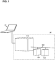
- FIG. 1 is a schematic diagram showing a configuration of a system in which an executable program according to the embodiment of the present invention is executed.
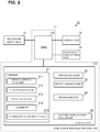
- FIG. 2 is a diagram showing a configuration of an executable program creation device according to the embodiment of the present invention.
- FIG. 1 A system in which the executable program according to the present embodiment is used is described first, with reference to FIG. 1 .
- a system 90 shown in FIG. 1 is an FA (Factory Automation) system.
- the system 90 includes an industrial controller 910, devices 921 and 922, and a network 900.
- the industrial controller 910, the device 921, and the device 922 are connected to each other via the network 900.
- the devices 921 and 922 include motion equipment, such as a motor, and a control unit controlling an operation of the motion equipment.
- the devices 921 and 922 are not limited to this, and may be any device that includes a predetermined operation unit and a control unit controlling an operation of the predetermined operation unit.
- the industrial controller 910 is connectable to a personal computer 10, as shown in FIG. 1 .
- the executable program executed by the industrial controller 910 is created by the personal computer 10.
- the industrial controller 910 downloads and stores the executable program created by the personal computer 10. It should be noted that the industrial controller 910 stores a device variable table described later.
- the industrial controller 910 and the personal computer 10 store the same device variable table.
- the industrial controller 910 controls the devices 921 and 922 connected to the industrial controller 910 via the network 900.
- the device variable table is described in detail later.
- the personal computer 10 includes an executable program creation unit 11, an operation input unit 12, a communication control unit 13, and a display unit 14.
- the operation input unit 12 is, for example, a mouse and a keyboard.
- the display unit 14 is, for example, a liquid crystal display.
- the communication control unit 13 performs control to communicate with the industrial controller 910. Via this communication control unit 13, the industrial controller 910 downloads the executable program.
- the executable program creation unit 11 corresponds to the executable program creation device according to the present invention, and includes a CPU 111 and a storage unit 112.
- the storage unit 112 stores various programs, tables, and so forth. To be more specific, the storage unit 112 stores a compiler 21, a library manager 22, a device variable table 23, a program editor 24, a function replacement rule editor 25.
- the compiler 21 stores a lexical-syntactical analyzer 211, a function replacer 212, a code generator 213, an assembler 214, and a function replacement rule table 215.
- the CPU 111 corresponds to the arithmetic unit according to the present invention, and executes a program stored in the storage unit 112 to create the executable program. In doing so, the CPU 111 creates the executable program by reference to a necessary table.
- the program editor 24 writes and edits source code as the source of the executable program.
- An editing screen of the program editor 24 is displayed on the display unit 14 on which, for example, source code and various commands inputted from the operation input unit 12 are displayed.
- the function replacement rule editor 25 writes and edits a dummy function, a replacement function, and a function replacement rule described later, for example.
- the dummy function, the replacement function, and the function replacement rule are stored in a library (not shown) included in the storage unit 112.
- the library manager 22 manages various kinds of data stored in the library. Storage information on the dummy function, the replacement function, and the function replacement rule are registered in the library manager 22.
- a "function" as used in the present specification is a "language element which, when executed, typically yields one data element result and possibly additional output variables.”
- a function is a structural unit used for program management and includes information on, for example, the name of the function, an argument variable group, a return value variable, and code representing processing including functions and procedures. Through a function call, a function allows the processing to be called to a different location of the program to be executed.
- the device variable table 23 stores variables and attributes for each device, for example.
- the device variable table 23 has a data structure as shown in FIG. 3.
- FIG. 3 is a diagram showing the data structure of the device variable table.
- the device variable table 23 stores the devices included in the system 90 in association with variables and attributes of the respective device.
- the number of devices, the number of variables, and the number of attributes are set in accordance with the device. Examples of the attribute include data type and endianness.
- device A has variables A1 and A2
- variable A1 has the attributes data type A11 and endianness A12, for example.
- the compiler 21 compiles the source code and creates a relocatable object.
- the lexical-syntactical analyzer 211 creates an intermediate representation IR from the source code.
- the function replacer 212 extracts function call processing included in the intermediate representation IR.
- the function replacer 212 determines whether a function replacement condition is satisfied. If the function replacement condition is satisfied, the function replacer 212 replaces the function call processing according to the function replacement rule.
- the function replacement rule table 215 stores the function replacement rules stored in the library via the library manager 22 on the basis of the intermediate representation IR.
- FIG. 4 is a diagram showing the data structure of the function replacement rule table.
- the function replacement rule table 215 stores the function call processing extracted from the intermediate representation IR and the function replacement rules.
- FUNC1 which is subjected to the function call processing, is stored in association with FUNC1 replacement rule 1 (replacement rule 11) and FUNC2 replacement rule (replacement rule 12), for example.
- the code generator 213 creates code using the intermediate representation IR including the replacement function call processing.
- the assembler 214 creates a relocatable object from the generated code.
- the dummy function, the replacement function, and the function replacement rule are previously set on the basis of the details in the device variable table 23, that is, the characteristics of variables of the device.
- the function call included in the intermediate representation IR calls an appropriate replacement function corresponding to the device characteristics.
- the relocatable object is appropriate in view of the device characteristics.
- an appropriate executable program corresponding to the device characteristics is created.
- the industrial controller 910 transmits, to a post-change device (i.e. the changed device), a control command corresponding to the characteristics of this post-change device. In other words, even when the device is changed, the source code does not need to be rewritten.
- FIG. 5 is a flowchart showing a method for creating a library as the source of the function replacement rule table.
- the executable program creation unit 11 receives a description of a dummy function (S101).
- the executable program creation unit 11 receives a description of a replacement function (S102).
- the executable program creation unit 11 receives a description of a function replacement rule (S103).
- the executable program creation unit 11 stores the dummy function, the replacement function, and the function replacement rule into the library, and registers the dummy function, the replacement function, and the function replacement rule in the library manager 22 (S104).
- FIG. 6 is a flowchart showing main processing of the method for creating the executable program according to the present embodiment of the present invention.
- the executable program creation unit 11 receives a description of source code (S11). After receiving the description of source code, the executable program creation unit 11 receives a build instruction (S12).
- the executable program creation unit 11 When receiving the build instruction, the executable program creation unit 11 performs compile processing with a function replacement rule on the source code (S13). As a result, a relocatable object is created.
- the executable program creation unit 11 performs link processing on the relocatable object (S14). As a result, an executable program is created.
- FIG. 7 is a flowchart of compilation processing with a function replacement rule.
- the executable program creation unit 11 performs a lexical-syntactical analysis on the source code (S21).
- the source code is written by the programmer using the dummy function.
- an intermediate representation IR is created.
- the executable program creation unit 11 extracts each function call processing included in the intermediate representation IR.
- the executable program creation unit 11 detects whether a function replacement rule is given for each function included the intermediate representation IR. Then, the executable program creation unit 11 extracts the given function replacement rule and registers this function replacement rule in the function replacement rule table 215. In doing so, the executable program creation unit 11 registers the dummy function and the replacement function in the function replacement rule table 215 together with the function replacement rule.
- the executable program creation unit 11 performs replacement of the function call (S23).
- the processing of function call replacement is described with reference to FIG. 8 later.
- the executable program creation unit 11 creates code using the intermediate representation IR obtained after the processing of function call replacement (that is, the intermediate representation IR using the replacement function) (S24). Then, the executable program creation unit 11 assembles the code (S25). As a result, a relocatable object is created.
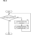
- FIG. 8 is a flowchart showing processing of function call replacement.
- the executable program creation unit 11 changes the function call subjected to the replacement processing (S31: NO ⁇ S32).
- the executable program creation unit 11 performs the individual processing on the function call subjected to the replacement processing (S33). The individual processing is described with reference to FIG. 9 .
- the executable program creation unit 11 ends the processing of function call replacement.
- FIG. 9 is a flowchart showing the individual processing.
- the executable program creation unit 11 detects whether the function of the function call subjected to the processing (i.e., the function subjected to the processing) is registered in the function replacement rule table 215. More specifically, the executable program creation unit 11 detects whether the function corresponds to one of FUNC1, FUNC2 ... shown in FIG. 4 .
- step S42 If the function subjected to the processing is not registered in the function replacement rule table 215 (S41: NO), the executable program creation unit 11 ends the processing without performing the replacement processing on this function call. If the function subjected to the processing is registered in the function replacement rule table 215 (S41: YES), the executable program creation unit 11 proceeds to step S42.
- step S42 the executable program creation unit 11 obtains, from the function replacement rule table 215, a function replacement condition group corresponding to the function subjected to the processing. For instance, in the example shown in FIG. 4 , when detecting that the function subjected to the processing is FUNC1, the executable program creation unit 11 obtains the replacement rule 11 and the replacement rule 12.
- the executable program creation unit 11 evaluates the function replacement condition. To be more specific, the executable program creation unit 11 detects whether the function replacement condition is satisfied.
- FIG. 10 is a diagram showing an example of a data structure of a library in data-type-based replacement processing.
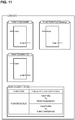
- FIG. 11 is a diagram showing an example of a data structure of a library in endianness-based replacement processing.
- the device is a control device for a motor.
- the program of each function is indicated in ladder notation.
- the library stores "FUNCTION (Motor 32)", “FUNCTION (Motor 64)”, “FUNCTION (Motor) (Dummy)", and the replacement rules.
- the library stores “FUNCTION (Motor 32)” having Parameter 1 of DWORD type and Parameter 2 of REAL type.
- the library stores “FUNCTION (Motor 64)” having Parameter 1 of LWORD type and Parameter 2 of LREAL type.
- "FUNCTION (Motor)" (Dummy) has the same program structure as FUNCTION (Motor 32) and “FUNCTION (Motor 64)", but no data type is designated.
- the replacement rules the name of the function is stored in association with the condition (replacement condition) and processing.
- the library stores "FUNCTION (SWAP)”, “FUNCTION (MOVE)”, “FUNCTION (TLE) (Dummy)", and the replacement rules.
- “FUNCTION (SWAP)” is a so-called SWAP function.
- "FUNCTION (MOVE)” is a so-called MOVE function.
- "FUNCTION (TLE) (Dummy)” is a dummy program for endianness conversion.
- the configuration, the method, and the program according to the present embodiment allows an executable program that is appropriate for the device controlled by the executable program to be automatically created without the need for the programmer to consider the device characteristics, such as data type or endianness, when writing the source code.
Landscapes
- Engineering & Computer Science (AREA)
- Software Systems (AREA)
- Theoretical Computer Science (AREA)
- General Engineering & Computer Science (AREA)
- Physics & Mathematics (AREA)
- General Physics & Mathematics (AREA)
- Computing Systems (AREA)
- Stored Programmes (AREA)
Abstract
Description
- The present invention relates to a technology of creating an executable program to be executed by an industrial controller.
- At present, various systems that include an industrial controller to control a plurality of devices (appliances) are put to practical use. For example, a system disclosed in Non-Patent
Document 1 includes an industrial controller (a machine automation controller) that is connected to various devices via a control network. Moreover, the industrial controller is connectable to an executable program creation device, such as a personal computer. - Software for creating an executable program is installed on the personal computer. Using this software, a programmer creates source code as the source of the executable program. The building of the source code creates the executable program. The executable program created using the personal computer is transferred to the industrial controller.
- The industrial controller stores the executable program transferred from the personal computer. The industrial controller executes this executable program to perform device control, such as setting of control parameters of various devices.
- Non-Patent Document 1: Machine Automation Controller Overview on Control Equipment of Omron, on the Internet: http://www.fa.omron.co.jp/guide/technicalguide/454/270/index.html
- However, the devices connected to the industrial controller may have characteristics affecting the executable program. For this reason, the programmer needs to create a source file corresponding to such characteristics.
- For example, suppose that the device is changed from device A to device B and that device A and device B have different characteristics. In this case, the programmer needs to rewrite the source code corresponding to device A into source code corresponding to device B and rebuild the source code.
- In view of this, it is an object of the present invention to provide a technology for creating an executable program corresponding to characteristics of a device by using source code having less dependence on the characteristics of the device.
- An executable program creation device according to the present invention includes a storage unit and an arithmetic unit. The storage unit stores a compiler program for compiling source code. The arithmetic unit creates an executable program by intermediately generating a relocatable object that is based on the source code, including execution of the compiler program.
- The arithmetic unit performs lexical-syntactical analysis to generate an intermediate representation from the source code, using the compiler program. The arithmetic unit extracts function call processing included in the intermediate representation. The arithmetic unit evaluates a function replacement condition set for the function call processing and corresponding to characteristics of a device controlled by the executable program. The arithmetic unit replaces the function call processing according to a function replacement rule if the function replacement condition is satisfied. The arithmetic unit intermediately generates a relocatable object using the replaced function call processing.
- With this configuration, the executable program including an appropriate function corresponding to the characteristics of the device is automatically created.
- According to the present invention, an executable program corresponding to characteristics of a device can be created while a burden on a programmer is reduced.
-
- Fig. 1
- is a schematic diagram showing a configuration of a system in which an executable program according to an embodiment of the present invention is executed.
- Fig. 2
- is a diagram showing a configuration of an executable program creation device according to an embodiment of the present invention.
- Fig. 3
- is a diagram showing a data structure of a device variable table.
- FIG. 4
- is a diagram showing a data structure of a function replacement rule table.
- FIG. 5
- is a flowchart showing a method for creating a library as the source of a function replacement rule table.
- FIG. 6
- is a flowchart showing main processing of a method for creating an executable program according to an embodiment of the present invention.
- FIG. 7
- is a flowchart showing compilation processing with a function replacement rule.
- FIG. 8
- is a flowchart showing processing of function call replacement.
- FIG. 9
- is a flowchart showing individual processing.
- FIG. 10
- is a diagram showing an example of a data structure of a library in data-type-based replacement processing.
- FIG. 11
- is a diagram showing an example of a data structure of a library in endianness-based replacement processing.
- A technology for creating an executable program according to an embodiment of the present embodiment is described, with reference to the accompanying drawings.
FIG. 1 is a schematic diagram showing a configuration of a system in which an executable program according to the embodiment of the present invention is executed.FIG. 2 is a diagram showing a configuration of an executable program creation device according to the embodiment of the present invention. - A system in which the executable program according to the present embodiment is used is described first, with reference to
FIG. 1 . To be more specific, asystem 90 shown inFIG. 1 is an FA (Factory Automation) system. Thesystem 90 includes anindustrial controller 910,devices network 900. - As shown in
FIG. 1 , theindustrial controller 910, thedevice 921, and thedevice 922 are connected to each other via thenetwork 900. Thedevices devices - Moreover, the
industrial controller 910 is connectable to apersonal computer 10, as shown inFIG. 1 . The executable program executed by theindustrial controller 910 is created by thepersonal computer 10. Theindustrial controller 910 downloads and stores the executable program created by thepersonal computer 10. It should be noted that theindustrial controller 910 stores a device variable table described later. Theindustrial controller 910 and thepersonal computer 10 store the same device variable table. - By executing the executable program with reference to the device variable table, the
industrial controller 910 controls thedevices industrial controller 910 via thenetwork 900. The device variable table is described in detail later. - As shown in
FIG. 2 , thepersonal computer 10 includes an executableprogram creation unit 11, anoperation input unit 12, acommunication control unit 13, and adisplay unit 14. Theoperation input unit 12 is, for example, a mouse and a keyboard. Thedisplay unit 14 is, for example, a liquid crystal display. Thecommunication control unit 13 performs control to communicate with theindustrial controller 910. Via thiscommunication control unit 13, theindustrial controller 910 downloads the executable program. - The executable
program creation unit 11 corresponds to the executable program creation device according to the present invention, and includes aCPU 111 and astorage unit 112. Thestorage unit 112 stores various programs, tables, and so forth. To be more specific, thestorage unit 112 stores acompiler 21, alibrary manager 22, a device variable table 23, aprogram editor 24, a functionreplacement rule editor 25. Thecompiler 21 stores a lexical-syntactical analyzer 211, afunction replacer 212, acode generator 213, anassembler 214, and a function replacement rule table 215. - The
CPU 111 corresponds to the arithmetic unit according to the present invention, and executes a program stored in thestorage unit 112 to create the executable program. In doing so, theCPU 111 creates the executable program by reference to a necessary table. - For example, the
program editor 24 writes and edits source code as the source of the executable program. An editing screen of theprogram editor 24 is displayed on thedisplay unit 14 on which, for example, source code and various commands inputted from theoperation input unit 12 are displayed. - The function
replacement rule editor 25 writes and edits a dummy function, a replacement function, and a function replacement rule described later, for example. The dummy function, the replacement function, and the function replacement rule are stored in a library (not shown) included in thestorage unit 112. Thelibrary manager 22 manages various kinds of data stored in the library. Storage information on the dummy function, the replacement function, and the function replacement rule are registered in thelibrary manager 22. - It should be noted that, as described in JIS 3503: 2016 (IEC 61131-3), which is the programming language standard for programmable controllers, a "function" as used in the present specification is a "language element which, when executed, typically yields one data element result and possibly additional output variables." A function is a structural unit used for program management and includes information on, for example, the name of the function, an argument variable group, a return value variable, and code representing processing including functions and procedures. Through a function call, a function allows the processing to be called to a different location of the program to be executed.
- The device variable table 23 stores variables and attributes for each device, for example. To be more specific, the device variable table 23 has a data structure as shown in
FIG. 3. FIG. 3 is a diagram showing the data structure of the device variable table. The device variable table 23 stores the devices included in thesystem 90 in association with variables and attributes of the respective device. The number of devices, the number of variables, and the number of attributes are set in accordance with the device. Examples of the attribute include data type and endianness. In example shown inFIG. 3 , device A has variables A1 and A2, and variable A1 has the attributes data type A11 and endianness A12, for example. - Generally speaking, the
compiler 21 compiles the source code and creates a relocatable object. The lexical-syntactical analyzer 211 creates an intermediate representation IR from the source code. Thefunction replacer 212 extracts function call processing included in the intermediate representation IR. By reference to the function replacement rule table 215, thefunction replacer 212 determines whether a function replacement condition is satisfied. If the function replacement condition is satisfied, thefunction replacer 212 replaces the function call processing according to the function replacement rule. - Here, the function replacement rule table 215 stores the function replacement rules stored in the library via the
library manager 22 on the basis of the intermediate representation IR.FIG. 4 is a diagram showing the data structure of the function replacement rule table. The function replacement rule table 215 stores the function call processing extracted from the intermediate representation IR and the function replacement rules. In the example shown inFIG. 4 , FUNC1, which is subjected to the function call processing, is stored in association with FUNC1 replacement rule 1 (replacement rule 11) and FUNC2 replacement rule (replacement rule 12), for example. - The
code generator 213 creates code using the intermediate representation IR including the replacement function call processing. Theassembler 214 creates a relocatable object from the generated code. - Here, the dummy function, the replacement function, and the function replacement rule are previously set on the basis of the details in the device variable table 23, that is, the characteristics of variables of the device.
- Thus, by the execution of the above processing by the
compiler 21, the function call included in the intermediate representation IR calls an appropriate replacement function corresponding to the device characteristics. With this, even when the programmer creates the source code without consideration of the device characteristics, the relocatable object is appropriate in view of the device characteristics. Then, using this relocatable object, an appropriate executable program corresponding to the device characteristics is created. Moreover, when the device is changed and thus the device characteristics are also changed, theindustrial controller 910 transmits, to a post-change device (i.e. the changed device), a control command corresponding to the characteristics of this post-change device. In other words, even when the device is changed, the source code does not need to be rewritten. - Next, further specific processing of creating the executable program is described.
- First, processing of creating a library as the source of the function replacement rule table used during compilation is described.
FIG. 5 is a flowchart showing a method for creating a library as the source of the function replacement rule table. - As shown in
FIG. 5 , the executableprogram creation unit 11 receives a description of a dummy function (S101). The executableprogram creation unit 11 receives a description of a replacement function (S102). The executableprogram creation unit 11 receives a description of a function replacement rule (S103). The executableprogram creation unit 11 stores the dummy function, the replacement function, and the function replacement rule into the library, and registers the dummy function, the replacement function, and the function replacement rule in the library manager 22 (S104). -
FIG. 6 is a flowchart showing main processing of the method for creating the executable program according to the present embodiment of the present invention. - As shown in
FIG. 6 , the executableprogram creation unit 11 receives a description of source code (S11). After receiving the description of source code, the executableprogram creation unit 11 receives a build instruction (S12). - When receiving the build instruction, the executable
program creation unit 11 performs compile processing with a function replacement rule on the source code (S13). As a result, a relocatable object is created. - The executable
program creation unit 11 performs link processing on the relocatable object (S14). As a result, an executable program is created. - Next, specific processing of compilation processing with a function replacement rule is described.
FIG. 7 is a flowchart of compilation processing with a function replacement rule. - The executable
program creation unit 11 performs a lexical-syntactical analysis on the source code (S21). The source code is written by the programmer using the dummy function. By the execution of the lexical-syntactical analysis, an intermediate representation IR is created. - The executable
program creation unit 11 extracts each function call processing included in the intermediate representation IR. The executableprogram creation unit 11 detects whether a function replacement rule is given for each function included the intermediate representation IR. Then, the executableprogram creation unit 11 extracts the given function replacement rule and registers this function replacement rule in the function replacement rule table 215. In doing so, the executableprogram creation unit 11 registers the dummy function and the replacement function in the function replacement rule table 215 together with the function replacement rule. - The executable
program creation unit 11 performs replacement of the function call (S23). The processing of function call replacement is described with reference toFIG. 8 later. - The executable
program creation unit 11 creates code using the intermediate representation IR obtained after the processing of function call replacement (that is, the intermediate representation IR using the replacement function) (S24). Then, the executableprogram creation unit 11 assembles the code (S25). As a result, a relocatable object is created. - Next, specific processing of function call replacement is described.
FIG. 8 is a flowchart showing processing of function call replacement. - If the processing is not yet completed for all the function calls included in the intermediate representation IR, the executable
program creation unit 11 changes the function call subjected to the replacement processing (S31: NO → S32). - The executable
program creation unit 11 performs the individual processing on the function call subjected to the replacement processing (S33). The individual processing is described with reference toFIG. 9 . - If the processing is completed for all the function calls included in the intermediate representation IR, the executable
program creation unit 11 ends the processing of function call replacement. - Next, specific individual processing is described.
FIG. 9 is a flowchart showing the individual processing. - The executable
program creation unit 11 detects whether the function of the function call subjected to the processing (i.e., the function subjected to the processing) is registered in the function replacement rule table 215. More specifically, the executableprogram creation unit 11 detects whether the function corresponds to one of FUNC1, FUNC2 ... shown inFIG. 4 . - If the function subjected to the processing is not registered in the function replacement rule table 215 (S41: NO), the executable
program creation unit 11 ends the processing without performing the replacement processing on this function call. If the function subjected to the processing is registered in the function replacement rule table 215 (S41: YES), the executableprogram creation unit 11 proceeds to step S42. - In step S42, the executable
program creation unit 11 obtains, from the function replacement rule table 215, a function replacement condition group corresponding to the function subjected to the processing. For instance, in the example shown inFIG. 4 , when detecting that the function subjected to the processing is FUNC1, the executableprogram creation unit 11 obtains thereplacement rule 11 and thereplacement rule 12. - Next, the executable
program creation unit 11 evaluates the function replacement condition. To be more specific, the executableprogram creation unit 11 detects whether the function replacement condition is satisfied. - If the function replacement condition is satisfied (S43: YES), the executable
program creation unit 11 replaces the function call (S44). If the function replacement condition is not satisfied (S43: NO), the executableprogram creation unit 11 does not replace the function call corresponding to this condition. - If evaluation is not completed for all the function replacement conditions (S45: NO), the executable
program creation unit 11 repeats the evaluation. On the other hand, if evaluation is completed for all the function replacement conditions (S45: YES), the executableprogram creation unit 11 ends the individual processing. - The processing described thus far allows an appropriate executable program corresponding to the device characteristics to be automatically created without the need for the programmer to consider the device characteristics when writing the source code, as described above.
- Next, specific examples are described with reference to
FIG. 10 andFIG. 11 .FIG. 10 is a diagram showing an example of a data structure of a library in data-type-based replacement processing.FIG. 11 is a diagram showing an example of a data structure of a library in endianness-based replacement processing. InFIG. 10 andFIG. 11 , the device is a control device for a motor. Moreover, inFIG. 10 andFIG. 11 , the program of each function is indicated in ladder notation. - As shown in
FIG. 10 , for the data-type-based replacement processing, the library stores "FUNCTION (Motor 32)", "FUNCTION (Motor 64)", "FUNCTION (Motor) (Dummy)", and the replacement rules. The library stores "FUNCTION (Motor 32)" havingParameter 1 of DWORD type andParameter 2 of REAL type. Moreover, the library stores "FUNCTION (Motor 64)" havingParameter 1 of LWORD type andParameter 2 of LREAL type. Furthermore, "FUNCTION (Motor)" (Dummy) has the same program structure as FUNCTION (Motor 32) and "FUNCTION (Motor 64)", but no data type is designated. - In the replacement rules, the name of the function is stored in association with the condition (replacement condition) and processing. For example, the replacement rules state that if "
Parameter 1 = DWORD type" and "Parameter 2 = REAL type" is given as the replacement condition, then "FUNCTION (Motor)" is replaced by "FUNCTION (Motor 32)" as the processing. Moreover, the replacement rules state that if "Parameter 1 = LWORD type" and "Parameter 2 = LREAL type" is given as the replacement condition, then "FUNCTION (Motor)" is replaced by "FUNCTION (Motor 64)" as the processing. - In this way, when detecting the call of "FUNCTION (Motor)" in the intermediate representation IR, the executable
program creation unit 11 creates a relocatable object in which the call of "FUNCTION (Motor 32)" is executed if "Parameter 1 = DWORD type" and "Parameter 2 = REAL type" is given and in which the call of "FUNCTION (Motor 64)" is executed when "Parameter 1 = LWORD type" and "Parameter 2 = LREAL type" is given. Then, theindustrial controller 910 executes the executable program including this relocatable object. - As shown in
FIG. 11 , for the endianness-based replacement processing, the library stores "FUNCTION (SWAP)", "FUNCTION (MOVE)", "FUNCTION (TLE) (Dummy)", and the replacement rules. "FUNCTION (SWAP)" is a so-called SWAP function. "FUNCTION (MOVE)" is a so-called MOVE function. "FUNCTION (TLE) (Dummy)" is a dummy program for endianness conversion. - In the replacement rules, the name of the function is stored in association with the condition (replacement condition) and processing. For example, the replacement rules state that if "input = Big" is given as the replacement condition, then "FUNCTION (TLE)" is replaced by "FUNCTION (SWAP)" as the processing. Moreover, the replacement rules state that if "input = Little" is given as the replacement condition, then "FUNCTION (TLE)" is replaced by "FUNCTION (Move)" as the processing.
- In this way, when detecting the call of "FUNCTION (TLE)" in the intermediate representation IR, the executable
program creation unit 11 creates a relocatable object in which the call of "FUNCTION (SWAP)" is executed if "input = Big" is given and in which the call of "FUNCTION (Move)" is executed if "input = Little" is given. Then, theindustrial controller 910 executes the executable program including this relocatable object. - As described thus far, the configuration, the method, and the program according to the present embodiment allows an executable program that is appropriate for the device controlled by the executable program to be automatically created without the need for the programmer to consider the device characteristics, such as data type or endianness, when writing the source code.
- 10 ... personal computer, 11 ... executable program creation unit, 12 ... operation input unit, 13 ... communication control unit, 14 ... display unit, 21 ... compiler, 22 ... library manager, 23 ... device variable table, 24 ... program editor, 25 ... function replacement rule editor, 90 ... system, 111 ... CPU, 112 ... storage unit, 211 ... lexical-syntactical analyzer, 212 ... function replacer, 212 ... replacer, 213 ... code generator, 214 ... assembler, 215 ... function replacement rule table, 900 ... network, 910 ... industrial controller, 921 ... device, 922 ... device
Claims (5)
- An executable program creation device comprising:a storage unit storing a compiler program for compiling source code; andan arithmetic unit configured to create an executable program by intermediately generating a relocatable object that is based on the source code, including execution of the compiler program,wherein the arithmetic unit is configured to, using the compiler program:perform lexical-syntactical analysis to generate an intermediate representation from the source code;extract function call processing included in the intermediate representation;replace the extracted function call processing in accordance with a function replacement rule if a function replacement condition set corresponding to characteristics of a device controlled by the executable program is satisfied; andintermediately generate the relocatable object using the replaced function call processing.
- The executable program creation device according to claim 1,
wherein the compiler program stored in the storage unit has a function replacement rule table including the function replacement condition, and
the arithmetic unit is configured to evaluate the function replacement condition if a function subjected to call processing corresponds to the function replacement condition stored in the function replacement rule table. - The executable program creation device according to one of claim 1 and claim 2,
wherein the storage unit stores a function library, and
the function library includes:a dummy function used for the source code; anda plurality of replacement functions corresponding to the dummy function. - An executable program creation method for creating an executable program by intermediately generating a relocatable object that is based on the source code, including compilation of source code, the executable program creation method comprising:performing lexical-syntactical analysis to generate an intermediate representation from the source code;evaluating a function replacement condition corresponding to function call processing included in the intermediate representation;replacing the extracted function call processing according to a function replacement rule if the function replacement condition is satisfied; andintermediately generating the relocatable object using the replaced function call processing.
- An executable program creation program causing a computer to execute processing of creating an executable program by intermediately generating a relocatable object that includes compilation of source code and that is based on the source code, the executable program creation program causing the computer to execute:performing lexical-syntactical analysis to generate an intermediate representation from the source code;evaluating a function replacement condition corresponding to function call processing included in the intermediate representation;replacing the extracted function call processing according to a function replacement rule if the function replacement condition is satisfied; andintermediately generating the relocatable object using the replaced function call processing.
Applications Claiming Priority (2)
| Application Number | Priority Date | Filing Date | Title |
|---|---|---|---|
| JP2016176464A JP2018041373A (en) | 2016-09-09 | 2016-09-09 | Executable program creation device, executable program creation method, and executable program creation program |
| PCT/JP2017/030047 WO2018047620A1 (en) | 2016-09-09 | 2017-08-23 | Executable program creation device, executable program creation method, and executable program creation program |
Publications (2)
| Publication Number | Publication Date |
|---|---|
| EP3511827A1 true EP3511827A1 (en) | 2019-07-17 |
| EP3511827A4 EP3511827A4 (en) | 2019-12-25 |
Family
ID=61562401
Family Applications (1)
| Application Number | Title | Priority Date | Filing Date |
|---|---|---|---|
| EP17848563.7A Withdrawn EP3511827A4 (en) | 2016-09-09 | 2017-08-23 | Executable program creation device, executable program creation method, and executable program creation program |
Country Status (5)
| Country | Link |
|---|---|
| US (1) | US20190196798A1 (en) |
| EP (1) | EP3511827A4 (en) |
| JP (1) | JP2018041373A (en) |
| CN (1) | CN109564518A (en) |
| WO (1) | WO2018047620A1 (en) |
Families Citing this family (5)
| Publication number | Priority date | Publication date | Assignee | Title |
|---|---|---|---|---|
| CN110389753B (en) * | 2019-06-06 | 2024-01-23 | 五八有限公司 | Chained calling method and device of native application, electronic equipment and storage medium |
| JP6736139B1 (en) * | 2019-08-07 | 2020-08-05 | 株式会社オリンピア | Amusement machine |
| JP6736138B1 (en) * | 2019-08-07 | 2020-08-05 | 株式会社オリンピア | Amusement machine |
| CN113268469B (en) * | 2021-06-11 | 2022-09-06 | 福建天晴数码有限公司 | Method and system for automatically creating actors |
| CN113791979B (en) * | 2021-09-16 | 2023-12-22 | 平安国际智慧城市科技股份有限公司 | Dynamic debugging method and device for software product, computer equipment and storage medium |
Family Cites Families (11)
| Publication number | Priority date | Publication date | Assignee | Title |
|---|---|---|---|---|
| US20030074656A1 (en) * | 2001-09-14 | 2003-04-17 | Yoshiaki Irino | Program execution apparatus and method, computer program for performing the program execution method, image forming system, and address solution method |
| US7065757B2 (en) * | 2001-09-28 | 2006-06-20 | Hewlett-Packard Development Company, L.P. | Efficient compilation of family of related functions |
| GB2420638A (en) * | 2004-11-24 | 2006-05-31 | Hewlett Packard Development Co | Method of substituting code fragments in Internal Representation |
| JP4985461B2 (en) * | 2008-02-25 | 2012-07-25 | 日本電気株式会社 | Compiler, compiling method, and program |
| JP2009258796A (en) * | 2008-04-11 | 2009-11-05 | Toshiba Corp | Program development device and program development method |
| US8370822B2 (en) * | 2008-11-20 | 2013-02-05 | Apple Inc. | Compiling techniques for providing limited accuracy and enhanced performance granularity |
| US8434059B2 (en) * | 2009-05-01 | 2013-04-30 | Apple Inc. | Systems, methods, and computer-readable media for fertilizing machine-executable code |
| JP5655448B2 (en) * | 2010-09-09 | 2015-01-21 | 富士電機株式会社 | PLC system and its development support equipment |
| EP2687981B1 (en) * | 2012-07-18 | 2017-12-27 | MStar Semiconductor, Inc. | Automated compiler specialisation for global optimisation |
| CN104391730B (en) * | 2014-08-03 | 2017-07-11 | 浙江网新恒天软件有限公司 | A kind of software source codes language translation system and method |
| CN104536751B (en) * | 2014-12-26 | 2018-04-06 | 小米科技有限责任公司 | Webpage source code moving method and device |
-
2016
- 2016-09-09 JP JP2016176464A patent/JP2018041373A/en active Pending
-
2017
- 2017-08-23 WO PCT/JP2017/030047 patent/WO2018047620A1/en not_active Ceased
- 2017-08-23 CN CN201780050048.5A patent/CN109564518A/en active Pending
- 2017-08-23 US US16/325,207 patent/US20190196798A1/en not_active Abandoned
- 2017-08-23 EP EP17848563.7A patent/EP3511827A4/en not_active Withdrawn
Also Published As
| Publication number | Publication date |
|---|---|
| CN109564518A (en) | 2019-04-02 |
| EP3511827A4 (en) | 2019-12-25 |
| WO2018047620A1 (en) | 2018-03-15 |
| JP2018041373A (en) | 2018-03-15 |
| US20190196798A1 (en) | 2019-06-27 |
Similar Documents
| Publication | Publication Date | Title |
|---|---|---|
| Hästbacka et al. | Model-driven development of industrial process control applications | |
| US20190196798A1 (en) | Executable program creation device, executable program creation method, and executable program creation program | |
| US11215960B2 (en) | Engineering apparatus, control method of engineering apparatus, and program for generating executable code for controlling target hardware | |
| US8056062B2 (en) | Methods and systems for converting application code in turbine control systems | |
| US20110126179A1 (en) | Method and System for Dynamic Patching Software Using Source Code | |
| JP6954256B2 (en) | Engineering equipment, control methods and programs for engineering equipment | |
| KR20110045853A (en) | Computer Software Test Method and System | |
| CN108345451B (en) | Continuous function diagram programming method | |
| Romero-Garcés et al. | Improving the lifecycle of robotics components using domain-specific languages | |
| US11256481B2 (en) | Software development environment with compilation and read-evaluate-print-loop operations | |
| CN110968051A (en) | Method and engineering system for planning automation systems | |
| Julius et al. | A model-driven approach for transforming GRAFCET specification into PLC code including hierarchical structures | |
| CN101561779A (en) | Debugging method and debugger | |
| JP7238678B2 (en) | Information processing equipment, support programs and support systems | |
| JP4301976B2 (en) | Programming tools | |
| CN114518734B (en) | Control model integration method, device and medium thereof | |
| JP6483507B2 (en) | Control program creating apparatus and control program debugging method | |
| Dorninger et al. | Automated reengineering of industrial HMI screens by static analysis | |
| EP4427128B1 (en) | Developing an app, especially updating a workflow of the app | |
| JP7631921B2 (en) | Development support device, development support method, and development support program | |
| EP4636515A1 (en) | Development assistance device, development assistance method, and development assistance program | |
| JP5091520B2 (en) | Hybrid model simulation device | |
| Kim et al. | On-demand materialization of aspects for application development | |
| JP2013235381A (en) | Data editing apparatus and data editing method | |
| WO2022190418A1 (en) | Development assitance device, development assitance method, and development assitance program |
Legal Events
| Date | Code | Title | Description |
|---|---|---|---|
| STAA | Information on the status of an ep patent application or granted ep patent |
Free format text: STATUS: THE INTERNATIONAL PUBLICATION HAS BEEN MADE |
|
| PUAI | Public reference made under article 153(3) epc to a published international application that has entered the european phase |
Free format text: ORIGINAL CODE: 0009012 |
|
| STAA | Information on the status of an ep patent application or granted ep patent |
Free format text: STATUS: REQUEST FOR EXAMINATION WAS MADE |
|
| 17P | Request for examination filed |
Effective date: 20190212 |
|
| AK | Designated contracting states |
Kind code of ref document: A1 Designated state(s): AL AT BE BG CH CY CZ DE DK EE ES FI FR GB GR HR HU IE IS IT LI LT LU LV MC MK MT NL NO PL PT RO RS SE SI SK SM TR |
|
| AX | Request for extension of the european patent |
Extension state: BA ME |
|
| DAV | Request for validation of the european patent (deleted) | ||
| DAX | Request for extension of the european patent (deleted) | ||
| A4 | Supplementary search report drawn up and despatched |
Effective date: 20191127 |
|
| RIC1 | Information provided on ipc code assigned before grant |
Ipc: G06F 9/44 20180101AFI20191121BHEP Ipc: G06F 8/41 20180101ALI20191121BHEP Ipc: G06F 8/72 20180101ALI20191121BHEP |
|
| STAA | Information on the status of an ep patent application or granted ep patent |
Free format text: STATUS: THE APPLICATION HAS BEEN WITHDRAWN |
|
| 18W | Application withdrawn |
Effective date: 20200407 |