EP3511561A1 - Rotorblatt für eine windenergieanlage, windenergieanlage sowie halterung - Google Patents
Rotorblatt für eine windenergieanlage, windenergieanlage sowie halterung Download PDFInfo
- Publication number
- EP3511561A1 EP3511561A1 EP18151383.9A EP18151383A EP3511561A1 EP 3511561 A1 EP3511561 A1 EP 3511561A1 EP 18151383 A EP18151383 A EP 18151383A EP 3511561 A1 EP3511561 A1 EP 3511561A1
- Authority
- EP
- European Patent Office
- Prior art keywords
- rotor blade
- attachment points
- holder
- bottom plate
- control cabinet
- Prior art date
- Legal status (The legal status is an assumption and is not a legal conclusion. Google has not performed a legal analysis and makes no representation as to the accuracy of the status listed.)
- Granted
Links
Images



Classifications
-
- F—MECHANICAL ENGINEERING; LIGHTING; HEATING; WEAPONS; BLASTING
- F03—MACHINES OR ENGINES FOR LIQUIDS; WIND, SPRING, OR WEIGHT MOTORS; PRODUCING MECHANICAL POWER OR A REACTIVE PROPULSIVE THRUST, NOT OTHERWISE PROVIDED FOR
- F03D—WIND MOTORS
- F03D1/00—Wind motors with rotation axis substantially parallel to the air flow entering the rotor
- F03D1/06—Rotors
- F03D1/065—Rotors characterised by their construction elements
- F03D1/0675—Rotors characterised by their construction elements of the blades
-
- F—MECHANICAL ENGINEERING; LIGHTING; HEATING; WEAPONS; BLASTING
- F05—INDEXING SCHEMES RELATING TO ENGINES OR PUMPS IN VARIOUS SUBCLASSES OF CLASSES F01-F04
- F05B—INDEXING SCHEME RELATING TO WIND, SPRING, WEIGHT, INERTIA OR LIKE MOTORS, TO MACHINES OR ENGINES FOR LIQUIDS COVERED BY SUBCLASSES F03B, F03D AND F03G
- F05B2260/00—Function
- F05B2260/30—Retaining components in desired mutual position
-
- F—MECHANICAL ENGINEERING; LIGHTING; HEATING; WEAPONS; BLASTING
- F05—INDEXING SCHEMES RELATING TO ENGINES OR PUMPS IN VARIOUS SUBCLASSES OF CLASSES F01-F04
- F05B—INDEXING SCHEME RELATING TO WIND, SPRING, WEIGHT, INERTIA OR LIKE MOTORS, TO MACHINES OR ENGINES FOR LIQUIDS COVERED BY SUBCLASSES F03B, F03D AND F03G
- F05B2260/00—Function
- F05B2260/30—Retaining components in desired mutual position
- F05B2260/301—Retaining bolts or nuts
-
- F—MECHANICAL ENGINEERING; LIGHTING; HEATING; WEAPONS; BLASTING
- F05—INDEXING SCHEMES RELATING TO ENGINES OR PUMPS IN VARIOUS SUBCLASSES OF CLASSES F01-F04
- F05B—INDEXING SCHEME RELATING TO WIND, SPRING, WEIGHT, INERTIA OR LIKE MOTORS, TO MACHINES OR ENGINES FOR LIQUIDS COVERED BY SUBCLASSES F03B, F03D AND F03G
- F05B2260/00—Function
- F05B2260/96—Preventing, counteracting or reducing vibration or noise
- F05B2260/964—Preventing, counteracting or reducing vibration or noise by damping means
-
- Y—GENERAL TAGGING OF NEW TECHNOLOGICAL DEVELOPMENTS; GENERAL TAGGING OF CROSS-SECTIONAL TECHNOLOGIES SPANNING OVER SEVERAL SECTIONS OF THE IPC; TECHNICAL SUBJECTS COVERED BY FORMER USPC CROSS-REFERENCE ART COLLECTIONS [XRACs] AND DIGESTS
- Y02—TECHNOLOGIES OR APPLICATIONS FOR MITIGATION OR ADAPTATION AGAINST CLIMATE CHANGE
- Y02E—REDUCTION OF GREENHOUSE GAS [GHG] EMISSIONS, RELATED TO ENERGY GENERATION, TRANSMISSION OR DISTRIBUTION
- Y02E10/00—Energy generation through renewable energy sources
- Y02E10/70—Wind energy
- Y02E10/72—Wind turbines with rotation axis in wind direction
Definitions
- the invention relates to a rotor blade for a wind power plant, which has a rotor blade root area and a base plate arranged within the rotor blade root area.
- the invention also relates to a wind energy plant with at least one such rotor blade.
- Rotor blade wind turbines are well known in the art and are used to convert wind energy into electrical energy.
- a bottom plate which can also be referred to as a bulkhead, bulkhead or partition. This is typically mounted within the rotor blade in the rotor blade root area.
- a floor panel generally has two functions.
- the bottom plate serves as a working platform for workers when maintenance or repair work must be carried out within a rotor blade.
- such a bottom plate is used to protect against flying parts, such as waste that may fall, for example, from the rotor blade into the hub of the wind turbine.
- Such a rotor blade is for example from the international application WO 2012/119934 A1 known.
- An object on which the invention is based is to provide a mounting concept which contributes to a reliable attachment of objects to the floor panel.
- a rotor blade for a wind energy plant has a rotor blade root portion and a bottom plate fixedly connected within the rotor blade root portion to an inner wall of the rotor blade.
- the rotor blade has a control cabinet, which has several first attachment points. Further, a holder is provided which has one or more second attachment points at which the holder is fixed directly to the bottom plate. On the bracket of the cabinet is directly attached by means of the first attachment points. In this case, the or the second attachment points of the holder - projected into a plane spanned by the first attachment points - lie within a first polygon formed by the first attachment points.
- a wind turbine and thus its rotor blades are typically exposed during operation high forces due to acting wind loads. These forces can cause the rotor blades to deform or deform, in particular elastically. Due to the fact that the bottom plate is firmly connected in the rotor blade root area with an inner wall of the rotor blade, the forces continue on the bottom plate, which can then also be deformed, for example, ovalized. As a result, high shear forces can act on joints, such as bolted joints, and on the typically rigid and rigid electrical cabinet when directly and directly connected to the floorboard itself.
- a decoupling of the direct mounting of the cabinet is provided with the bottom plate.
- the holder is mounted as a decoupling element between the control cabinet and base plate.
- the attachment points of the Floor plate attachment structurally decoupled from those of the cabinet mounting. Due to the fact that the second attachment point (s) of the attachment lie within the first polygon, in the case of a second attachment point there is no or, in the case of at least two second attachment points, only slight relative movements between the second attachment points. Relative movements between the first mounting points of the cabinet are almost completely avoided, since the deformations and movements of the bottom plate can no longer act directly on the cabinet. Otherwise, in particular very high shear forces would act on the attachment points.
- the rotor blade allows the integration or the provision of damping measures, for example in the connection of the holder to the bottom plate or in the design of the holder itself. This further contributes to the aforementioned advantages and functions. This contributes to the prevention or reduction of vibrations that occur during the deformation or movement of the bottom plate.
- Another advantage of the rotor blade described is that different cabinet sizes are possible with identical attachment of a bracket to the bottom plate. As a result, a modularity or flexibility is increased or made possible.
- fastening point describes, depending on the context, a point of a single component as well as a point in which two components are connected to one another. Synonyms are the terms connection point or mounting point.
- the rotor blade root area is typically hollow like the entire rotor blade, wherein in the rotor blade root area of the rotor blade, the base plate is rigidly and rigidly connected to the inner wall or fixed or anchored to the inner wall. In cross-section, the rotor blade root area, in contrast to the remaining part of the rotor blade, is typically circular or substantially circular.
- the rotor blade root area is assigned to a rotor hub and, in the installed state, faces the rotor hub.
- the bottom plate is fixedly coupled to the inner wall at several points of an edge of the bottom plate, for example. The coupling can be carried out for example by gluing, screwing or rigid connection adapter.
- the bracket is, for example, a console or a structure with support arms, as described below.
- the holder is formed, for example, as a sheet metal forming part.
- the holder has a comparatively low manufacturing and cost.
- the control cabinet is a structurally rigid or rigid element, wherein typically electrical components and cables are arranged inside.
- the holder has at least two second attachment points, wherein a smallest distance of adjacent corners of the first polygon is greater than a smallest second distance between the two second attachment points.
- This contributes to the above advantage and functions.
- second distance which may be, for example, 20 cm, and for example 50, 60, 70 or 80% lower than that the first distance between adjacent first attachment points
- relative movements between the second attachment points are relatively low, so that no negative effects on the connection of the holder to the bottom plate are to be expected even with a deformation of the bottom plate.
- the mechanical coupling with the bottom plate is generally improved, in particular, momentary forces in the individual attachment points being reduced.
- the holder has three or more second fastening points which define a second polygon, wherein a surface of the first polygon is greater than an area of the second polygon by at least 50%, preferably 60%, particularly preferably 70% or 80% ,
- the holder is designed as a supporting structure and has a base plate with the one or more second attachment points. From the base plate extend one or more support arms to each of which the control cabinet is attached via a first attachment point.
- the holder is designed as a bracket.
- the console has a base plate with the one or more second attachment points.
- control cabinet is welded and / or screwed in the first attachment points with the holder and / or the holder in the second attachment points with the bottom plate.
- support such as the structure or the console, as welded assembly and / or Verschraubungsbaury added.
- the holder is at least partially resilient.
- the wings or the support arms are resilient.
- the support arms or wings extend at a small angle from the base plate, so that a spring effect is achieved.
- Such an effect can be enhanced or achieved, for example, if the holder is manufactured as a sheet-metal forming part, for example made of spring steel. Due to the resilient design is contributed to the compensation of manufacturing tolerances and to achieve damping properties.
- the holder has one or more damping elements.
- the support arms which may also be referred to as a structural boom, have damping properties or have integral Damping elements as components.
- only the support arms or wings are formed damping and / or resilient with respect to the base plate.
- a free space or gap is formed between the control cabinet and the bottom plate at least in the region of the first attachment points.
- no direct connection between the bottom plate and the cabinet is provided. The fact that a free space or gap is formed at least in the areas of the first attachment points, it is helped that the bottom plate can move or deform relative to the cabinet.
- a wind power plant which has a rotor with one or more rotor blades according to one of the above-described embodiments.
- a holder which is designed to fix a cabinet to a bottom plate of the rotor blade.
- the wind turbine and the bracket essentially allow the aforementioned advantages and functions.
- FIG. 1 shows a schematic representation of a wind turbine 100 according to an embodiment.
- the wind energy plant 100 has a tower 101.
- the tower 101 is fixed by means of a foundation on a substrate.
- a nacelle 102 is rotatably mounted.
- the nacelle 102 has, for example, a generator which is coupled to a rotor 103 via a rotor shaft (not shown).
- the rotor 103 has one or more rotor blades 104, which are arranged on a rotor hub 105.
- the rotor 103 is operated by an air flow, such as wind, along a main flow direction 124 flows in, set in rotation. This rotational movement is transmitted via the rotor shaft and optionally a transmission to the generator.
- the generator converts the kinetic energy of the rotor 103 into electrical energy.
- FIG. 2 shows an exemplary rotor blade 104 of the wind turbine 100.
- the rotor blade 104 has the shape of a conventional rotor blade and has a rotor blade root portion 106 which faces and is associated with the rotor hub 105.
- the rotor blade root region 106 typically has a substantially circular cross-section.
- the rotor blade root region 106 is adjoined by a transition region 107 and a profile region 108 of the rotor blade 104.
- the rotor blade 104 has a pressure side 109 and an opposite suction side 110 with respect to the longitudinal extension direction 125.
- the rotor blade 104 is formed substantially hollow in the interior.
- a bottom plate 111 is arranged, which is fixedly connected to an inner wall 112 of the rotor blade 104 in the rotor blade root portion 106.
- a rigid connection is provided between the shell of the rotor blade 104 and the bottom plate 111.
- the bottom plate 111 is circular in the embodiment and may optionally have one or more vents through which people can pass to gain access to the interior of the rotor blade 104.
- the bottom plate 111 acts as a seal against dirt and / or moisture.
- the bottom plate 111 optionally serves as the corresponding one Work platform during maintenance or installation work on the rotor hub 105 or the rotor blade 104 itself.
- the control cabinet 113 is a component or a body which is substantially rigid and rigid.
- the cabinet 113 has a rigid housing. Wiring, wiring, interconnections or other electrical and mechanical components can be arranged inside the housing, which is immaterial to the idea of the invention described above.
- FIG. 3 is a plan view of the cabinet 113 is shown.
- the control cabinet On the outside of a housing 114, the control cabinet has four first attachment points 115 in the corner regions.
- the first attachment points 115 define a first polygon, in this case with four corners, wherein adjacent corners or attachment points 115 have first distances a1 to one another.
- the distances are, for example, 460 mm and 560 mm.
- the control cabinet 113 can be mounted on the base plate 111, for which purpose, for example, mounting adapter (not shown) can be used.
- mounting adapter With the help of this mounting adapter, the relatively rigid control cabinet 113 is bolted directly to the generally softer and deformable bottom plate 111.
- the mounting adapters are based on a double-sided bonding on the bottom plate surface, combined with a bolted connection or clamping through the bottom plate.
- FIGS. 4 to 6 describe an alternative, improved attachment of a cabinet 113 to the bottom plate 111 according to the invention.
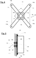
- FIG. 4 shows a holder 116, which is formed in the embodiment as a supporting structure with support arms 117.
- the holder 116 which is embodied for example as a sheet-metal forming part, has a central base plate 118, which has four second attachment points 119, via which the holder 116, as in cross-section in FIG FIG. 5 shown attached to the bottom plate 111.
- mounting adapter 120 may be used, which are glued to both sides of the bottom plate 111 and carry a bolt which protrudes on the cabinet 113 facing side and the base plate 118 can be screwed.
- the control cabinet 113 itself is mounted on the support arms 117 via its first attachment points 115, the latter having corresponding attachment points 115a.
- the support arms 117 are optionally resilient.
- the above-mentioned decoupling of the attachment points in the bottom plate attachment and the cabinet mounting is achieved.
- a free space 121 or gap is formed between the control cabinet 113 and the bottom plate 111.
- the second attachment points 119 are arranged at a significantly smaller distance from each other than the first Attachment points 115.
- the second attachment points 119 define a second polygon, which in the exemplary embodiment is square. Adjacent second attachment points 119 or corners of the second polygon have a second distance a2 from each other.
- the second distance a2, in particular a smallest second distance a2 of all second distances a2, is significantly less than a smallest first distance a1 (of all first distances a1) of the first attachment points 115 (see FIG. FIG. 3 ).
- a smallest second distance a2 is less than a mean first distance of the first distances a1 of adjacent first attachment points 115 to one another, as in FIG FIG. 3 shown.
- the two surfaces A1 and A2 of the two defined polygons are also significantly different in terms of their sizes (s. FIG. 4 ).
- the area of the second polygon is more than 50% less than that of the first polygon.
- the second attachment points 119 projected into a plane spanned by the first attachment points 115, lie within the first polygon formed by the first attachment points 115.
- FIG. 6 shows in a schematic view of the cabinet 113, which is mounted on the bracket 116.
- FIG. 7 shows an alternative embodiment of the holder 116, which in the embodiment according to FIG. 7 a console is.
- This holder 116 is also distinguished by a base plate 118, from which two wings 123 each extend at opposite edges 122.
- the wings have attachment points 115a, which correspond to the first attachment points 115 of the cabinet 113, in which the two elements are mechanically connected to each other.
- the two wings 123 are resilient, esp. With respect to the base plate 118 is formed.
- the wings 123 are at an angle relative to the main plane of extension of the base plate 118 from the latter.
- the holder 116 may have damper 126.
- damper 126 For example, in the assembled state between the holder 116 and the control cabinet 113 in the region of the first attachment points 115 one or more damper elements are mounted. Additionally or alternatively, one or more damper elements are arranged between the base plate 118 and the bottom plate 111.
Landscapes
- Engineering & Computer Science (AREA)
- Life Sciences & Earth Sciences (AREA)
- Sustainable Development (AREA)
- Sustainable Energy (AREA)
- Chemical & Material Sciences (AREA)
- Combustion & Propulsion (AREA)
- Mechanical Engineering (AREA)
- General Engineering & Computer Science (AREA)
- Wind Motors (AREA)
Abstract
Description
- Die Erfindung betrifft ein Rotorblatt für eine Windenergieanlage, welches einen Rotorblattwurzelbereich und eine innerhalb des Rotorblattwurzelbereichs angeordnete Bodenplatte aufweist. Die Erfindung betrifft auch eine Windenergieanlage mit zumindest einem solchen Rotorblatt.
- Windenergieanlagen mit Rotorblättern sind aus dem Stand der Technik vielfach bekannt und werden verwendet, um Windenergie in elektrische Energie umzuwandeln. Im Bereich einer Rotorblattwurzel sind Rotorblätter typischerweise mit einer Bodenplatte, die auch als Schott, Schottwand oder Trennwand bezeichnet werden kann, ausgestattet. Diese ist typischerweise innerhalb des Rotorblattes im Rotorblattwurzelbereich montiert. Eine derartige Bodenplatte hat im Allgemeinen zwei Funktionen. Zum einen dient die Bodenplatte als Arbeitsplattform für Arbeiter, wenn Wartungs- oder Reparaturarbeiten innerhalb eines Rotorblatts vorgenommen werden müssen. Zum anderen dient eine solche Bodenplatte dem Schutz vor herumfliegenden Teilen, etwa Abfällen, die beispielsweise aus dem Rotorblatt in die Nabe der Windenergieanlage fallen können. Ein derartiges Rotorblatt ist beispielsweise aus der internationalen Anmeldung
WO 2012/119934 A1 bekannt. - Eine Aufgabe, die der Erfindung zugrunde liegt, ist es, ein Montagekonzept anzugeben, welches zu einer verlässlichen Befestigung von Objekten an der Bodenplatte beiträgt.
- Es wird ein Rotorblatt für eine Windenergieanlage offenbart. Das Rotorblatt hat einen Rotorblattwurzelbereich und eine Bodenplatte, die fest innerhalb des Rotorblattwurzelbereichs mit einer Innenwand des Rotorblatts verbunden ist. Das Rotorblatt hat einen Schaltschrank, der mehrere erste Befestigungspunkte hat. Weiter ist eine Halterung vorgesehen, die einen oder mehrere zweite Befestigungspunkte aufweist, an denen die Halterung direkt an der Bodenplatte festgelegt ist. An der Halterung ist der Schaltschrank mittels der ersten Befestigungspunkte direkt befestigt. Dabei liegen der oder die zweiten Befestigungspunkte der Halterung - projiziert in eine durch die ersten Befestigungspunkte aufgespannte Ebene - innerhalb eines durch die ersten Befestigungspunkte gebildeten ersten Vielecks.
- Eine Windenergieanlage und damit deren Rotorblätter sind im Betrieb typischerweise hohen Kräften aufgrund von wirkenden Windlasten ausgesetzt. Diese Kräfte können dazu führen, dass sich die Rotorblätter verformen bzw. deformieren, insbesondere elastisch. Aufgrund der Tatsache, dass die Bodenplatte fest in dem Rotorblattwurzelbereich mit einer Innenwand des Rotorblatts verbunden ist, setzen sich die Kräfte auf die Bodenplatte fort, die daraufhin ebenfalls deformiert werden kann, beispielsweise ovalisiert. Infolgedessen können hohe Scherkräfte auf Anbindungen, etwa Bolzenverschraubungen, und auf den typischerweise starren und steifen Schaltschrank wirken, wenn dieser direkt und unmittelbar mit der Bodenplatte selbst verbunden ist.
- Bei dem beschriebenen Rotorblatt ist eine Entkopplung der direkten Befestigung des Schaltschranks mit der Bodenplatte vorgesehen. Mit anderen Worten wird die Halterung als Entkopplungselement zwischen Schaltschrank und Bodenplatte montiert. Dadurch sind die Befestigungspunkte der Bodenplattenbefestigung strukturell von denen der Schaltschrankbefestigung entkoppelt. Dadurch, dass der oder die zweiten Befestigungspunkte der Halterung innerhalb des ersten Vielecks liegen, gibt es im Falle von einem zweiten Befestigungspunkt gar keine oder im Falle von zumindest zwei zweiten Befestigungspunkten nur geringe Relativbewegungen zwischen den zweiten Befestigungspunkten. Relativbewegungen zwischen den ersten Befestigungspunkten des Schaltschranks werden nahezu gänzlich vermieden, da die Verformungen und Bewegungen der Bodenplatte nicht mehr direkt auf den Schaltschrank einwirken können. Andernfalls würden insbesondere sehr hohe Scherkräfte auf die Befestigungspunkte einwirken.
- Weiterhin ermöglicht das Rotorblatt die Integration oder das Vorsehen von Dämpfungsmaßnahmen, beispielsweise bei der Anbindung der Halterung an die Bodenplatte oder beim Ausgestalten der Halterung selbst. Dadurch wird weiter zu den vorgenannten Vorteilen und Funktionen beigetragen. Dadurch wird zur Vermeidung oder Reduktion von Schwingungen, die bei der Verformung oder Bewegung der Bodenplatte auftreten, beigetragen.
- Ein weiterer Vorteil bei dem beschriebenen Rotorblatt besteht darin, dass unterschiedliche Schaltschrankgrößen bei identischer Befestigung einer Halterung an der Bodenplatte möglich sind. Dadurch wird eine Modularität beziehungsweise Flexibilität erhöht beziehungsweise ermöglicht.
- Hier und im Folgenden gilt, dass der Begriff Befestigungspunkt je nach Kontext einen Punkt einer einzelnen Komponente als auch einen Punkt, in welchem zwei Komponenten miteinander verbunden sind, beschreibt. Als Synonyme gelten die Begriffe Anbindungspunkt oder Montagepunkt.
- Der Rotorblattwurzelbereich ist typischerweise wie das gesamte Rotorblatt im Inneren hohl ausgebildet, wobei in dem Rotorblattwurzelbereich des Rotorblatts die Bodenplatte fest und steif mit der Innenwand verbunden beziehungsweise an der Innenwand festgelegt oder verankert ist. Im Querschnitt ist der Rotorblattwurzelbereich im Unterschied zu dem restlichen Teil des Rotorblattes typischerweise kreisrund oder im Wesentlichen kreisförmig ausgebildet. Der Rotorblattwurzelbereich ist einer Rotornabe zugeordnet und im montierten Zustand der Rotornabe zugewandt. Die Bodenplatte ist beispielsweise an mehreren Stellen eines Rands der Bodenplatte mit der Innenwand fest gekoppelt. Die Kopplung kann beispielsweise durch Verklebungen, Verschraubungen oder mittels steifer Verbindungsadapter ausgeführt sein.
- Bei der Halterung handelt es sich beispielsweise um eine Konsole oder ein Tragwerk mit Tragarmen, etwa wie weiter unten beschrieben. Die Halterung ist beispielsweise als Blechumformteil ausgebildet. Die Halterung hat einen vergleichsweise geringen Herstell- und Kostenaufwand.
- Bei dem Schaltschrank handelt es sich um ein strukturell steifes oder starres Element, wobei im Inneren typischerweise elektrische Komponenten und Kabel angeordnet sind.
- Gemäß einer Ausführungsform weist die Halterung zumindest zwei zweite Befestigungspunkte auf, wobei ein geringster Abstand benachbarter Ecken des ersten Vielecks größer ist als ein geringster zweiter Abstand zwischen den beiden zweiten Befestigungspunkten. Dadurch wird zu dem obigen Vorteil und Funktionen beigetragen. Insbesondere aufgrund des deutlich geringeren zweiten Abstands, der beispielsweise 20 cm betragen kann, und beispielsweise 50, 60, 70 oder 80 % geringer als der erste Abstand benachbarter erster Befestigungspunkte ist, sind Relativbewegungen zwischen den zweiten Befestigungspunkten verhältnismäßig gering, sodass auch bei einer Deformation der Bodenplatte keine negativen Auswirkungen auf die Anbindung der Halterung an die Bodenplatte zu erwarten sind. Durch die Ausbildung mehrerer zweiter Befestigungspunkte wird allgemein die mechanische Kopplung mit der Bodenplatte verbessert, wobei insb. Momentkräfte in den einzelnen Befestigungspunkten reduziert werden.
- Gemäß einer Ausführungsform weist die Halterung drei oder mehr zweite Befestigungspunkte auf, die ein zweites Vieleck definieren, wobei eine Fläche des ersten Vielecks um mindestens 50 %, bevorzugt 60 %, besonders bevorzugt 70 % oder 80%, größer ist als eine Fläche des zweiten Vielecks.
- Analog zu oben spiegelt sich in den Flächenverhältnissen ein deutlich geringerer Abstand zwischen den zweiten Befestigungspunkten des zweiten Vielecks im montierten Zustand wieder, wodurch es zu deutlich geringeren Relativbewegungen untereinander kommt.
- Die zuvor beschriebenen Ausführungsformen sind alternativ auch vorstellbar, ohne dass der oder die zweiten Befestigungspunkte innerhalb des ersten Vielecks liegen. Auch derartige Ausgestaltungen ermöglichen im Wesentlichen die eingangs genannten Vorteile und Funktionen, wenn zumindest eine der beschriebenen Abstands- bzw. Flächendefinitionen gemäß der beiden zuvor erwähnten Ausführungsformen erfüllt ist.
- Gemäß einer weiteren Ausführungsform ist die Halterung als Tragwerk ausgebildet und weist eine Grundplatte mit dem einen oder den mehreren zweiten Befestigungspunkten auf. Von der Grundplatte erstrecken sich ein oder mehrere Tragarme, an denen der Schaltschrank jeweils über einen ersten Befestigungspunkt befestigt ist.
- Gemäß einer Ausführungsform ist die Halterung als Konsole ausgebildet. Die Konsole hat beispielsweise eine Grundplatte mit dem einen oder den mehreren zweiten Befestigungspunkten. An sich gegenüberliegenden Rändern der Grundplatte erstreckt sich von der Grundplatte jeweils ein Flügel, an dem der Schaltschrank jeweils über einen oder mehrere erste Befestigungspunkte befestigt ist.
- Gemäß einer Ausführungsform ist der Schaltschrank in den ersten Befestigungspunkten mit der Halterung und/oder die Halterung in den zweiten Befestigungspunkten mit der Bodenplatte verschweißt und/oder verschraubt. Somit wird die Halterung, etwa das Tragwerk oder die Konsole, als Schweißbaugruppe und/oder Verschraubungsbaugruppe gefügt.
- Gemäß einer Ausführungsform ist die Halterung zumindest teilweise federnd ausgebildet. Beispielsweise sind die Flügel oder die Tragarme federnd ausgebildet. Beispielsweise erstrecken sich die Tragarme oder Flügel unter einem kleinen Winkel von der Grundplatte, sodass eine Federwirkung erzielt ist. Ein derartiger Effekt kann beispielsweise verstärkt oder erreicht werden, wenn die Halterung als ein Blechumformteil, beispielsweise aus Federstahl, gefertigt ist. Durch die federnde Ausbildung wird zur Kompensation von Fertigungstoleranzen sowie zum Erreichen von Dämpfungseigenschaften beigetragen.
- Gemäß einer Ausführungsform weist die Halterung ein oder mehrere Dämpfungselemente auf. Beispielsweise weisen die Tragarme, die auch als Tragwerkausleger bezeichnet werden können, dämpfende Eigenschaften auf oder weisen integrale Dämpfungselemente als Bestandteile auf. Beispielsweise sind nur die Tragarme oder Flügel dämpfend ausgebildet und/oder federnd ausgebildet bezüglich der Grundplatte.
- Gemäß einer Ausführungsform ist zwischen dem Schaltschrank und der Bodenplatte zumindest im Bereich der ersten Befestigungspunkte ein Freiraum oder Spalt ausgebildet. Mit anderen Worten ist keine direkte Verbindung zwischen der Bodenplatte und dem Schaltschrank vorgesehen. Dadurch, dass ein Freiraum oder Spalt zumindest in den Bereichen der ersten Befestigungspunkte ausgebildet ist, wird dazu beigetragen, dass sich die Bodenplatte relativ zu dem Schaltschrank bewegen beziehungsweise deformieren kann.
- Des Weiteren wird eine Windenergieanlage offenbart, die einen Rotor mit einem oder mehreren Rotorblättern nach einer der vorbeschriebenen Ausführungsformen aufweist.
- Des Weiteren wird eine Halterung offenbart, die entsprechend ausgebildet ist, einen Schaltschrank an einer Bodenplatte des Rotorblatts zu fixieren.
- Die Windenergieanlage und die Halterung ermöglichen im Wesentlichen die vorgenannten Vorteile und Funktionen.
- Weitere Vorteile, Merkmale und Weiterbildungen ergeben sich aus den nachfolgenden, in Verbindung mit den Figuren erläuterten Ausführungsbeispielen. Gleiche, gleichartige oder gleich wirkende Elemente sind in den Figuren mit den gleichen Bezugszeichen versehen.
- In den Figuren zeigen:
-
Figur 1 eine schematische Darstellung einer Windenergieanlage gemäß einem Ausführungsbeispiel, -
Figur 2 eine schematische Darstellung eines Rotorblatts der Windenergieanlage, -
Figur 3 eine schematische Darstellung eines Schaltschranks für die Windenergieanalage, -
Figur 4 eine schematische Darstellung einer Halterung für den Schaltschrank, -
Figur 5 eine schematische Schnittansicht der Halterung und des Schaltschranks in einem montierten Zustand, -
Figur 6 eine schematische Aufsicht des montierten Zustands und -
Figur 7 eine Halterung gemäß einem zweiten Ausführungsbeispiel. -
Figur 1 zeigt eine schematische Darstellung einer Windenergieanlage 100 gemäß einem Ausführungsbeispiel. Die Windenergieanlage 100 weist einen Turm 101 auf. Der Turm 101 ist mittels eines Fundaments auf einem Untergrund befestigt. An einem dem Untergrund gegenüberliegenden Ende des Turms 101 ist eine Gondel 102 drehbar gelagert. Die Gondel 102 weist beispielsweise einen Generator auf, der über eine Rotorwelle (nicht gezeigt) mit einem Rotor 103 gekoppelt ist. Der Rotor 103 weist ein oder mehrere Rotorblätter 104 auf, die an einer Rotornabe 105 angeordnet sind. - Der Rotor 103 wird im Betrieb durch eine Luftströmung, beispielsweise Wind, der entlang einer Hauptströmungsrichtung 124 einströmt, in Rotation versetzt. Diese Rotationsbewegung wird über die Rotorwelle und gegebenenfalls ein Getriebe zu dem Generator übertragen. Der Generator wandelt die kinetische Energie des Rotors 103 in elektrische Energie um.
-
Figur 2 zeigt ein exemplarisches Rotorblatt 104 der Windenergieanlage 100. Das Rotorblatt 104 hat die Form eines herkömmlichen Rotorblattes und hat einen Rotorblattwurzelbereich 106, der der Rotornabe 105 zugewandt und zugeordnet ist. Der Rotorblattwurzelbereich 106 hat typischerweise einen im Wesentlichen kreisrunden Querschnitt. An den Rotorblattwurzelbereich 106 schließen sich ein Übergangsbereich 107 und ein Profilbereich 108 des Rotorblatts 104 an. Das Rotorblatt 104 hat bezüglich der Längserstreckungsrichtung 125 eine Druckseite 109 und eine gegenüberliegende Saugseite 110. Das Rotorblatt 104 ist im Inneren im Wesentlichen hohl ausgebildet. - Innerhalb des Rotorblattwurzelbereichs 106 ist eine Bodenplatte 111 angeordnet, die fest mit einer Innenwand 112 des Rotorblatts 104 im Rotorblattwurzelbereich 106 verbunden ist. Mit anderen Worten ist zwischen der Schale des Rotorblatts 104 und der Bodenplatte 111 eine steife Verbindung vorgesehen. Die Bodenplatte 111 ist im Ausführungsbeispiel kreisförmig ausgebildet und kann optional über ein oder mehrere Durchsteigeöffnungen verfügen, durch die Personen hindurchtreten können, um Zugang zum Inneren des Rotorblatts 104 zu erhalten. Durch die Bodenplatte 111 wird beispielsweise ein Hineinfallen von Gegenständen oder von Personen aus der Rotornabe 105 in das Rotorblatt 104 und umgekehrt verhindert. Zusätzlich oder alternativ fungiert die Bodenplatte 111 als Abdichtung gegenüber Schmutz und/oder Feuchtigkeit. Zudem dient die Bodenplatte 111 optional als entsprechende Arbeitsplattform bei Wartungs- oder Montagearbeiten an der Rotornabe 105 oder dem Rotorblatt 104 selbst.
- Aufgrund der verhältnismäßig großen, ungenutzten Fläche der Bodenplatte 111 ist angedacht, beispielsweise einen in
Figur 3 gezeigten Schaltschrank 113 an die Bodenplatte zu montieren. Bei dem Schaltschrank 113 handelt es sich um eine Komponente oder einen Körper, welcher im Wesentlichen steif und starr ausgebildet ist. Insbesondere hat der Schaltschrank 113 ein steifes Gehäuse. Im Inneren des Gehäuses können Verdrahtungen, Verkabelungen, Verschaltungen oder andere elektrische und mechanische Bauteile angeordnet sein, was jedoch für die Idee der eingangs beschriebenen Erfindung unwesentlich ist. - In
Figur 3 ist eine Aufsicht auf den Schaltschrank 113 gezeigt. Außen an einem Gehäuse 114 weist der Schaltschrank in den Eckbereichen vier erste Befestigungspunkte 115 auf. Die ersten Befestigungspunkte 115 definieren ein erstes Vieleck, in diesem Fall mit vier Ecken, wobei benachbarte Ecken beziehungsweise Befestigungspunkte 115 erste Abstände a1 zueinander haben. Bei den Abständen handelt es sich beispielsweise um 460 mm bzw. 560 mm. - Mittels der Befestigungspunkte 115 kann der Schaltschrank 113 an die Bodenplatte 111 montiert werden, wobei hierfür beispielsweise Montageadapter (nicht dargestellt) eingesetzt werden können. Mit Hilfe dieser Montageadapter wird der relativ starre Schaltschrank 113 direkt an der in der Regel weicheren und deformierbaren Bodenplatte 111 verschraubt. Die Montageadapter beruhen auf einer beidseitigen Verklebung auf der Bodenplattenoberfläche, kombiniert mit einer Bolzenverschraubung beziehungsweise Klemmung durch die Bodenplatte. Bei einer derartigen direkten Befestigung des Schaltschranks 113 an der Bodenplatte 111 können die eingangs genannten Verformungen und Biegungen der Bodenplatte 111 während eines Betriebes der Windenergieanlage 100 im schlimmsten Fall dazu führen, dass die Anbindung an die Bodenplatte 111 unter den wirkenden Scherkräften bricht und sich der Schaltschrank 113 von der Bodenplatte 111 löst.
-
Figuren 4 bis 6 beschreiben eine alternative, verbesserte Anbringung eines Schaltschranks 113 an die Bodenplatte 111 entsprechend der Erfindung. -
Figur 4 zeigt eine Halterung 116, die im Ausführungsbeispiel als Tragwerk mit Tragarmen 117 ausgebildet ist. Die Halterung 116, die beispielsweise als Blechumformteil ausgeführt ist, hat eine zentrale Grundplatte 118, die vier zweite Befestigungspunkte 119 aufweist, über die die Halterung 116, wie im Querschnitt inFigur 5 dargestellt, mit der Bodenplatte 111 befestigt wird. Auch hier können zur Befestigung der zentralen Grundplatte 118 Montageadapter 120 verwendet werden, die beidseitig an die Bodenplatte 111 geklebt sind und einen Bolzen tragen, der auf der dem Schaltschrank 113 zugewandten Seite absteht und über den die Grundplatte 118 verschraubt werden kann. Der Schaltschrank 113 selbst wird über dessen erste Befestigungspunkte 115 an die Tragarme 117 montiert, wobei letztere korrespondierende Befestigungspunkte 115a haben. Die Tragarme 117 sind optional federnd ausgebildet. - Dadurch ist die eingangs erwähnte Entkopplung der Befestigungspunkte bei der Bodenplattenbefestigung und der Schaltschrankbefestigung erreicht. Insbesondere in den Bereichen der ersten Befestigungspunkte 115 ist zwischen dem Schaltschrank 113 und der Bodenplatte 111 ein Freiraum 121 beziehungsweise Spalt ausgebildet. Die zweiten Befestigungspunkte 119 sind in einem deutlich geringeren Abstand zueinander angeordnet als die ersten Befestigungspunkte 115. Im Ausführungsbeispiel definieren die zweiten Befestigungspunkte 119 ein zweites Vieleck, welches im Ausführungsbeispiel quadratisch ist. Benachbarte zweite Befestigungspunkte 119 beziehungsweise Ecken des zweiten Vielecks haben einen zweiten Abstand a2 zueinander.
- Der zweite Abstand a2, insb. ein geringster zweiter Abstand a2 aller zweiten Abstände a2, ist deutlich geringer als ein geringster erster Abstand a1 (aller ersten Abstände a1) der ersten Befestigungspunkte 115 (s.
Figur 3 ). Insbesondere ist ein geringster zweiter Abstand a2 geringer als ein mittlerer erster Abstand der ersten Abstände a1 benachbarter erster Befestigungspunkte 115 zueinander, wie inFigur 3 gezeigt. Auch die beiden Flächen A1 und A2 der beiden definierten Vielecke sind hinsichtlich ihrer Größen deutlich unterschiedlich (s.Figur 4 ). Insbesondere ist die Fläche des zweiten Vielecks um mehr als 50% geringer als die des ersten Vielecks. - Darüber hinaus liegen die zweiten Befestigungspunkte 119, projiziert in eine durch die ersten Befestigungspunkte 115 aufgespannte Ebene, innerhalb des durch die ersten Befestigungspunkte 115 gebildeten ersten Vielecks. Eine derartige Ausgestaltung ermöglicht die eingangs genannten Vorteile und Funktionen.
-
Figur 6 zeigt in einer schematischen Ansicht den Schaltschrank 113, der an die Halterung 116 montiert ist. -
Figur 7 zeigt eine alternative Ausgestaltung der Halterung 116, die im Ausführungsbeispiel gemäßFigur 7 eine Konsole ist. Auch diese Halterung 116 zeichnet sich durch eine Grundplatte 118 aus, von der sich an gegenüberliegenden Rändern 122 jeweils zwei Flügel 123 erstrecken. Die Flügel haben Befestigungspunkte 115a, die zu den ersten Befestigungspunkten 115 des Schaltschranks 113 korrespondieren, in denen die beiden Elemente miteinander mechanisch verbunden werden. - Optional sind die beiden Flügel 123 federnd, insb. bezüglich der Grundplatte 118, ausgebildet. Beispielsweise stehen die Flügel 123 unter einem Winkel bezogen auf die Haupterstreckungsebene der Grundplatte 118 von letzterer ab.
- Wie in der Schnittdarstellung in
Figur 5 erkennbar, kann die Halterung 116 Dämpfer 126 aufweisen. Beispielsweise sind im montierten Zustand zwischen der Halterung 116 und dem Schaltschrank 113 im Bereich der ersten Befestigungspunkte 115 ein oder mehrere Dämpferelemente montiert. Zusätzlich oder alternativ sind zwischen der Grundplatte 118 und der Bodenplatte 111 ein oder mehrere Dämpferelemente angeordnet. -
- 100
- Windenergieanlage
- 101
- Turm
- 102
- Gondel
- 103
- Rotor
- 104
- Rotorblatt
- 105
- Rotornabe
- 106
- Rotorblattwurzelbereich
- 107
- Übergangsbereich
- 108
- Profilbereich
- 109
- Druckseite
- 110
- Saugseite
- 111
- Bodenplatte
- 112
- Innenwand
- 113
- Schaltschrank
- 114
- Gehäuse
- 115
- erster Befestigungspunkt
- 115a
- korrespondierender Befestigungspunkt
- 116
- Halterung
- 117
- Tragarm
- 118
- Grundplatte
- 119
- zweiter Befestigungspunkt
- 120
- Montageadapter
- 121
- Freiraum
- 122
- Rand
- 123
- Flügel
- 124
- Hauptströmungsrichtung
- 125
- Längserstreckungsrichtung
- 126
- Dämpfer
- a1
- erster Abstand
- a2
- zweiter Abstand
- A1
- Fläche erstes Vieleck
- A2
- Fläche zweites Vieleck
Claims (13)
- Rotorblatt (104) für eine Windenergieanlage (100), aufweisend- einen Rotorblattwurzelbereich (106);- eine Bodenplatte (111), die fest innerhalb des Rotorblattwurzelbereichs (106) mit einer Innenwand (112) des Rotorblatts (104) verbunden ist;- einen Schaltschrank (113), der mehrere erste Befestigungspunkte (115) aufweist; und- eine Halterung (116), die einen oder mehrere zweite Befestigungspunkte (119) aufweist, an denen die Halterung (116) an der Bodenplatte (111) festgelegt ist, und an der mittels der ersten Befestigungspunkte (115) der Schaltschrank (113) befestigt ist, wobei der oder die zweiten Befestigungspunkte (119) der Halterung (116) - projiziert in eine durch die ersten Befestigungspunkte (115) aufgespannte Ebene - innerhalb eines durch die ersten Befestigungspunkte (115) gebildeten ersten Vielecks liegen.
- Rotorblatt (104) nach Anspruch 1, wobei die Halterung (116) zumindest zwei zweite Befestigungspunkte (119) aufweist, wobei ein geringster erster Abstand (a1) zwischen benachbarten Ecken des ersten Vielecks größer ist als ein geringster zweiter Abstand (a2) zwischen den beiden zweiten Befestigungspunkten (119).
- Rotorblatt (104) nach Anspruch 1 oder 2, wobei die Halterung (116) drei oder mehr zweite Befestigungspunkte (119) aufweist, die ein zweites Vieleck definieren, wobei eine Fläche (A1) des ersten Vielecks um mindestens 50% größer ist als eine Fläche (A2) des zweiten Vielecks.
- Rotorblatt (104) nach einem der vorhergehenden Ansprüche, wobei die Halterung (116) als Tragwerk ausgebildet ist.
- Rotorblatt (104) nach Anspruch 4, wobei die Halterung (116) eine Grundplatte (118) mit dem einen oder den mehreren zweiten Befestigungspunkten (119) hat, wobei sich von der Grundplatte (118) ein oder mehrere Tragarme (117) erstrecken, an denen der Schaltschrank (113) jeweils über einen zum ersten Befestigungspunkt (115) korrespondierenden Befestigungspunkt (115a) befestigt ist.
- Rotorblatt (104) nach einem der Ansprüche 1 bis 3, wobei die Halterung (116) als Konsole ausgebildet ist.
- Rotorblatt (104) nach Anspruch 6, wobei die Halterung (116) eine Grundplatte (118) mit dem einen oder den mehreren zweiten Befestigungspunkten (119) hat, wobei sich an gegenüberliegenden Rändern der Grundplatte (122) von der Grundplatte (118) jeweils ein Flügel (123) erstreckt, an dem der Schaltschrank (113) jeweils über einen oder mehrere erste Befestigungspunkte (115) befestigt ist.
- Rotorblatt (104) nach einem der vorhergehenden Ansprüche, wobei der Schaltschrank (113) in den ersten Befestigungspunkten (115) mit der Halterung (116) verschweißt und/oder verschraubt ist.
- Rotorblatt (104) nach einem der vorhergehenden Ansprüche, wobei die Halterung (116) zumindest teilweise federnd ausgebildet ist.
- Rotorblatt (104) nach einem der vorhergehenden Ansprüche, wobei die Halterung (116) ein oder mehrere Dämpfungselemente (126) aufweist.
- Rotorblatt (104) nach einem der vorhergehenden Ansprüche, wobei zwischen dem Schaltschrank (113) und der Bodenplatte (111) zumindest im Bereich der ersten Befestigungspunkte (115) ein Freiraum oder Spalt (121) ausgebildet ist.
- Windenergieanlage (100), aufweisend
einen Rotor (103) mit einem oder mehreren Rotorblättern nach einem der vorhergehenden Ansprüche. - Halterung (116) für ein Rotorblatt (104) oder eine Windenergieanlage (100) nach einem der vorhergehenden Ansprüche, wobei- die Halterung (116) ausgebildet ist, einen Schaltschrank (113) an einer Bodenplatte (111) des Rotorblatts (104) zu fixieren,- die Halterung (116) einen oder mehrere zweite Befestigungspunkte (119) aufweist, an denen die Halterung (116) an der Bodenplatte (111) festlegbar ist, und an der mittels mehrerer erster Befestigungspunkte (115) der Schaltschrank (113) befestigbar ist, und- in einem betriebsgemäß montierten Zustand der oder die zweiten Befestigungspunkte (119) der Halterung (116) - projiziert in eine durch die ersten Befestigungspunkte (115) aufgespannte Ebene - innerhalb eines durch die ersten Befestigungspunkte (115) gebildeten ersten Vielecks liegen.
Priority Applications (3)
| Application Number | Priority Date | Filing Date | Title |
|---|---|---|---|
| ES18151383T ES2827835T3 (es) | 2018-01-12 | 2018-01-12 | Pala de rotor para un aerogenerador, aerogenerador, así como soporte |
| DK18151383.9T DK3511561T3 (da) | 2018-01-12 | 2018-01-12 | Rotorblad til et vindenergianlæg, vindenergianlæg og holder |
| EP18151383.9A EP3511561B1 (de) | 2018-01-12 | 2018-01-12 | Rotorblatt für eine windenergieanlage, windenergieanlage sowie halterung |
Applications Claiming Priority (1)
| Application Number | Priority Date | Filing Date | Title |
|---|---|---|---|
| EP18151383.9A EP3511561B1 (de) | 2018-01-12 | 2018-01-12 | Rotorblatt für eine windenergieanlage, windenergieanlage sowie halterung |
Publications (2)
| Publication Number | Publication Date |
|---|---|
| EP3511561A1 true EP3511561A1 (de) | 2019-07-17 |
| EP3511561B1 EP3511561B1 (de) | 2020-07-29 |
Family
ID=60957202
Family Applications (1)
| Application Number | Title | Priority Date | Filing Date |
|---|---|---|---|
| EP18151383.9A Not-in-force EP3511561B1 (de) | 2018-01-12 | 2018-01-12 | Rotorblatt für eine windenergieanlage, windenergieanlage sowie halterung |
Country Status (3)
| Country | Link |
|---|---|
| EP (1) | EP3511561B1 (de) |
| DK (1) | DK3511561T3 (de) |
| ES (1) | ES2827835T3 (de) |
Citations (5)
| Publication number | Priority date | Publication date | Assignee | Title |
|---|---|---|---|---|
| US20070119185A1 (en) * | 2005-11-23 | 2007-05-31 | Andreas Pfannenberg | Switch cupboard with a cooling device which is subject to a rotation and cooling device for this |
| US20120141284A1 (en) * | 2009-07-16 | 2012-06-07 | Astrium Sas | Device for assembling sections of wind-turbine blades and method for linking sections of wind-turbine blades |
| WO2012119934A1 (en) | 2011-03-08 | 2012-09-13 | Lm Wind Power A/S | Wind turbine blade comprising root end bulkhead |
| WO2017121753A1 (de) * | 2016-01-11 | 2017-07-20 | Ssb Wind Systems Gmbh & Co. Kg | Elektrischer schaltschrank |
| US20170314536A1 (en) * | 2014-10-30 | 2017-11-02 | Zhuzhou Times New Materials Technology Co., Ltd. | Anti-icing wind power blade and blade deicing and heating method |
-
2018
- 2018-01-12 EP EP18151383.9A patent/EP3511561B1/de not_active Not-in-force
- 2018-01-12 ES ES18151383T patent/ES2827835T3/es active Active
- 2018-01-12 DK DK18151383.9T patent/DK3511561T3/da active
Patent Citations (5)
| Publication number | Priority date | Publication date | Assignee | Title |
|---|---|---|---|---|
| US20070119185A1 (en) * | 2005-11-23 | 2007-05-31 | Andreas Pfannenberg | Switch cupboard with a cooling device which is subject to a rotation and cooling device for this |
| US20120141284A1 (en) * | 2009-07-16 | 2012-06-07 | Astrium Sas | Device for assembling sections of wind-turbine blades and method for linking sections of wind-turbine blades |
| WO2012119934A1 (en) | 2011-03-08 | 2012-09-13 | Lm Wind Power A/S | Wind turbine blade comprising root end bulkhead |
| US20170314536A1 (en) * | 2014-10-30 | 2017-11-02 | Zhuzhou Times New Materials Technology Co., Ltd. | Anti-icing wind power blade and blade deicing and heating method |
| WO2017121753A1 (de) * | 2016-01-11 | 2017-07-20 | Ssb Wind Systems Gmbh & Co. Kg | Elektrischer schaltschrank |
Non-Patent Citations (1)
| Title |
|---|
| NISHEETH SRIVASTAVA: "Mounting Bracket", 28 June 2014 (2014-06-28), XP002783094, Retrieved from the Internet <URL:https://www.youtube.com/watch?v=61ePVljEDAg> [retrieved on 20180716] * |
Also Published As
| Publication number | Publication date |
|---|---|
| ES2827835T3 (es) | 2021-05-24 |
| DK3511561T3 (da) | 2020-10-12 |
| EP3511561B1 (de) | 2020-07-29 |
Similar Documents
| Publication | Publication Date | Title |
|---|---|---|
| EP2273101B1 (de) | Verfahren zur montage von rotorblättern einer windenergieanlage | |
| DE102009003405B4 (de) | Windkraftanlagenflügel mit einem Blitzrezeptor | |
| DE10201726B4 (de) | Windenergieanlage | |
| WO2010072190A2 (de) | Arretierungsvorrichtung für den rotor von windenergieanlagen | |
| WO2017194545A1 (de) | Windenergieanlagen-rotorblatt, und windenergieanlage mit selbigem | |
| EP2928774B1 (de) | Einlauf für ein triebwerk eines luftfahrzeugs | |
| WO2014072157A1 (de) | Windenergieanlage | |
| EP2627898A1 (de) | Schott einer windenergieanlage | |
| WO2008003389A1 (de) | Rotornabe einer windenergieanlage | |
| DE20001636U1 (de) | Windkraftanlage für Dächer zur Energiegewinnung | |
| EP2740928A1 (de) | Windenergieanlage | |
| EP2568162B1 (de) | Windenergieanlage mit einer auf einem Turm angeordneten Gondel mit einem Übergang vom Dach der Gondel in den Rotor | |
| EP3775534A1 (de) | Rotornabe einer windenergieanlage, sowie verfahren zur montage einer solchen rotornabe | |
| EP3511561B1 (de) | Rotorblatt für eine windenergieanlage, windenergieanlage sowie halterung | |
| DE102018113760B4 (de) | Rotorlagergehäuse und Windenergieanlage mit Rotorlagergehäuse | |
| DE2951085A1 (de) | Vorrichtung zur ausnutzung von windenergie an bauwerken, insbesondere fassaden und daechern | |
| DE102010037706A1 (de) | Mast für eine Windenergieanlage | |
| EP3974602B1 (de) | Kopplungsvorrichtung zum koppeln von turmsegmenten eines turms einer windenergieanlage und montageverfahren hierfür | |
| DE10118407B4 (de) | Schwebeflügel-Windkraftanlage | |
| EP3242013A1 (de) | Windenergieanlage mit einer vorrichtung zum drehen einer gondel der windenergieanlage und verfahren zur montage einer vorrichtung zum drehen einer gondel | |
| WO2014040672A1 (de) | Lufteinlasssystem für eine stationäre brennkraftmaschine, insbesondere für eine stationäre gasturbine | |
| DE10218423A1 (de) | Windkraftanlage mit Vertikalrotoren | |
| AT525880B1 (de) | Paneel als Windenergiekonverter und dessen Verwendung | |
| EP2728174A1 (de) | Windkraftanlage zur Energiegewinnung | |
| WO2016005219A1 (de) | Energie-wandlung nach bernoulli-prinzip |
Legal Events
| Date | Code | Title | Description |
|---|---|---|---|
| PUAI | Public reference made under article 153(3) epc to a published international application that has entered the european phase |
Free format text: ORIGINAL CODE: 0009012 |
|
| STAA | Information on the status of an ep patent application or granted ep patent |
Free format text: STATUS: THE APPLICATION HAS BEEN PUBLISHED |
|
| AK | Designated contracting states |
Kind code of ref document: A1 Designated state(s): AL AT BE BG CH CY CZ DE DK EE ES FI FR GB GR HR HU IE IS IT LI LT LU LV MC MK MT NL NO PL PT RO RS SE SI SK SM TR |
|
| AX | Request for extension of the european patent |
Extension state: BA ME |
|
| STAA | Information on the status of an ep patent application or granted ep patent |
Free format text: STATUS: REQUEST FOR EXAMINATION WAS MADE |
|
| 17P | Request for examination filed |
Effective date: 20200109 |
|
| RBV | Designated contracting states (corrected) |
Designated state(s): AL AT BE BG CH CY CZ DE DK EE ES FI FR GB GR HR HU IE IS IT LI LT LU LV MC MK MT NL NO PL PT RO RS SE SI SK SM TR |
|
| GRAP | Despatch of communication of intention to grant a patent |
Free format text: ORIGINAL CODE: EPIDOSNIGR1 |
|
| STAA | Information on the status of an ep patent application or granted ep patent |
Free format text: STATUS: GRANT OF PATENT IS INTENDED |
|
| RIC1 | Information provided on ipc code assigned before grant |
Ipc: F03D 1/06 20060101AFI20200228BHEP |
|
| INTG | Intention to grant announced |
Effective date: 20200325 |
|
| GRAS | Grant fee paid |
Free format text: ORIGINAL CODE: EPIDOSNIGR3 |
|
| GRAA | (expected) grant |
Free format text: ORIGINAL CODE: 0009210 |
|
| STAA | Information on the status of an ep patent application or granted ep patent |
Free format text: STATUS: THE PATENT HAS BEEN GRANTED |
|
| AK | Designated contracting states |
Kind code of ref document: B1 Designated state(s): AL AT BE BG CH CY CZ DE DK EE ES FI FR GB GR HR HU IE IS IT LI LT LU LV MC MK MT NL NO PL PT RO RS SE SI SK SM TR |
|
| REG | Reference to a national code |
Ref country code: CH Ref legal event code: EP |
|
| REG | Reference to a national code |
Ref country code: AT Ref legal event code: REF Ref document number: 1296108 Country of ref document: AT Kind code of ref document: T Effective date: 20200815 |
|
| REG | Reference to a national code |
Ref country code: IE Ref legal event code: FG4D Free format text: LANGUAGE OF EP DOCUMENT: GERMAN |
|
| REG | Reference to a national code |
Ref country code: DE Ref legal event code: R096 Ref document number: 502018001965 Country of ref document: DE |
|
| REG | Reference to a national code |
Ref country code: DK Ref legal event code: T3 Effective date: 20201006 |
|
| REG | Reference to a national code |
Ref country code: LT Ref legal event code: MG4D |
|
| REG | Reference to a national code |
Ref country code: NL Ref legal event code: MP Effective date: 20200729 |
|
| PG25 | Lapsed in a contracting state [announced via postgrant information from national office to epo] |
Ref country code: FI Free format text: LAPSE BECAUSE OF FAILURE TO SUBMIT A TRANSLATION OF THE DESCRIPTION OR TO PAY THE FEE WITHIN THE PRESCRIBED TIME-LIMIT Effective date: 20200729 Ref country code: BG Free format text: LAPSE BECAUSE OF FAILURE TO SUBMIT A TRANSLATION OF THE DESCRIPTION OR TO PAY THE FEE WITHIN THE PRESCRIBED TIME-LIMIT Effective date: 20201029 Ref country code: GR Free format text: LAPSE BECAUSE OF FAILURE TO SUBMIT A TRANSLATION OF THE DESCRIPTION OR TO PAY THE FEE WITHIN THE PRESCRIBED TIME-LIMIT Effective date: 20201030 Ref country code: NO Free format text: LAPSE BECAUSE OF FAILURE TO SUBMIT A TRANSLATION OF THE DESCRIPTION OR TO PAY THE FEE WITHIN THE PRESCRIBED TIME-LIMIT Effective date: 20201029 Ref country code: HR Free format text: LAPSE BECAUSE OF FAILURE TO SUBMIT A TRANSLATION OF THE DESCRIPTION OR TO PAY THE FEE WITHIN THE PRESCRIBED TIME-LIMIT Effective date: 20200729 Ref country code: LT Free format text: LAPSE BECAUSE OF FAILURE TO SUBMIT A TRANSLATION OF THE DESCRIPTION OR TO PAY THE FEE WITHIN THE PRESCRIBED TIME-LIMIT Effective date: 20200729 Ref country code: SE Free format text: LAPSE BECAUSE OF FAILURE TO SUBMIT A TRANSLATION OF THE DESCRIPTION OR TO PAY THE FEE WITHIN THE PRESCRIBED TIME-LIMIT Effective date: 20200729 Ref country code: PT Free format text: LAPSE BECAUSE OF FAILURE TO SUBMIT A TRANSLATION OF THE DESCRIPTION OR TO PAY THE FEE WITHIN THE PRESCRIBED TIME-LIMIT Effective date: 20201130 |
|
| REG | Reference to a national code |
Ref country code: DE Ref legal event code: R082 Ref document number: 502018001965 Country of ref document: DE Representative=s name: EPPING HERMANN FISCHER PATENTANWALTSGESELLSCHA, DE Ref country code: DE Ref legal event code: R081 Ref document number: 502018001965 Country of ref document: DE Owner name: NORDEX ENERGY SE & CO. KG, DE Free format text: FORMER OWNER: NORDEX ENERGY GMBH, 22419 HAMBURG, DE |
|
| PG25 | Lapsed in a contracting state [announced via postgrant information from national office to epo] |
Ref country code: IS Free format text: LAPSE BECAUSE OF FAILURE TO SUBMIT A TRANSLATION OF THE DESCRIPTION OR TO PAY THE FEE WITHIN THE PRESCRIBED TIME-LIMIT Effective date: 20201129 Ref country code: PL Free format text: LAPSE BECAUSE OF FAILURE TO SUBMIT A TRANSLATION OF THE DESCRIPTION OR TO PAY THE FEE WITHIN THE PRESCRIBED TIME-LIMIT Effective date: 20200729 Ref country code: LV Free format text: LAPSE BECAUSE OF FAILURE TO SUBMIT A TRANSLATION OF THE DESCRIPTION OR TO PAY THE FEE WITHIN THE PRESCRIBED TIME-LIMIT Effective date: 20200729 Ref country code: RS Free format text: LAPSE BECAUSE OF FAILURE TO SUBMIT A TRANSLATION OF THE DESCRIPTION OR TO PAY THE FEE WITHIN THE PRESCRIBED TIME-LIMIT Effective date: 20200729 |
|
| PG25 | Lapsed in a contracting state [announced via postgrant information from national office to epo] |
Ref country code: NL Free format text: LAPSE BECAUSE OF FAILURE TO SUBMIT A TRANSLATION OF THE DESCRIPTION OR TO PAY THE FEE WITHIN THE PRESCRIBED TIME-LIMIT Effective date: 20200729 |
|
| PG25 | Lapsed in a contracting state [announced via postgrant information from national office to epo] |
Ref country code: SM Free format text: LAPSE BECAUSE OF FAILURE TO SUBMIT A TRANSLATION OF THE DESCRIPTION OR TO PAY THE FEE WITHIN THE PRESCRIBED TIME-LIMIT Effective date: 20200729 Ref country code: IT Free format text: LAPSE BECAUSE OF FAILURE TO SUBMIT A TRANSLATION OF THE DESCRIPTION OR TO PAY THE FEE WITHIN THE PRESCRIBED TIME-LIMIT Effective date: 20200729 Ref country code: RO Free format text: LAPSE BECAUSE OF FAILURE TO SUBMIT A TRANSLATION OF THE DESCRIPTION OR TO PAY THE FEE WITHIN THE PRESCRIBED TIME-LIMIT Effective date: 20200729 Ref country code: CZ Free format text: LAPSE BECAUSE OF FAILURE TO SUBMIT A TRANSLATION OF THE DESCRIPTION OR TO PAY THE FEE WITHIN THE PRESCRIBED TIME-LIMIT Effective date: 20200729 Ref country code: EE Free format text: LAPSE BECAUSE OF FAILURE TO SUBMIT A TRANSLATION OF THE DESCRIPTION OR TO PAY THE FEE WITHIN THE PRESCRIBED TIME-LIMIT Effective date: 20200729 |
|
| REG | Reference to a national code |
Ref country code: DE Ref legal event code: R097 Ref document number: 502018001965 Country of ref document: DE |
|
| REG | Reference to a national code |
Ref country code: ES Ref legal event code: FG2A Ref document number: 2827835 Country of ref document: ES Kind code of ref document: T3 Effective date: 20210524 |
|
| PG25 | Lapsed in a contracting state [announced via postgrant information from national office to epo] |
Ref country code: AL Free format text: LAPSE BECAUSE OF FAILURE TO SUBMIT A TRANSLATION OF THE DESCRIPTION OR TO PAY THE FEE WITHIN THE PRESCRIBED TIME-LIMIT Effective date: 20200729 |
|
| PLBE | No opposition filed within time limit |
Free format text: ORIGINAL CODE: 0009261 |
|
| STAA | Information on the status of an ep patent application or granted ep patent |
Free format text: STATUS: NO OPPOSITION FILED WITHIN TIME LIMIT |
|
| PG25 | Lapsed in a contracting state [announced via postgrant information from national office to epo] |
Ref country code: SK Free format text: LAPSE BECAUSE OF FAILURE TO SUBMIT A TRANSLATION OF THE DESCRIPTION OR TO PAY THE FEE WITHIN THE PRESCRIBED TIME-LIMIT Effective date: 20200729 |
|
| 26N | No opposition filed |
Effective date: 20210430 |
|
| PG25 | Lapsed in a contracting state [announced via postgrant information from national office to epo] |
Ref country code: SI Free format text: LAPSE BECAUSE OF FAILURE TO SUBMIT A TRANSLATION OF THE DESCRIPTION OR TO PAY THE FEE WITHIN THE PRESCRIBED TIME-LIMIT Effective date: 20200729 Ref country code: MC Free format text: LAPSE BECAUSE OF FAILURE TO SUBMIT A TRANSLATION OF THE DESCRIPTION OR TO PAY THE FEE WITHIN THE PRESCRIBED TIME-LIMIT Effective date: 20200729 |
|
| REG | Reference to a national code |
Ref country code: CH Ref legal event code: PL |
|
| PG25 | Lapsed in a contracting state [announced via postgrant information from national office to epo] |
Ref country code: LU Free format text: LAPSE BECAUSE OF NON-PAYMENT OF DUE FEES Effective date: 20210112 |
|
| REG | Reference to a national code |
Ref country code: BE Ref legal event code: MM Effective date: 20210131 |
|
| PG25 | Lapsed in a contracting state [announced via postgrant information from national office to epo] |
Ref country code: FR Free format text: LAPSE BECAUSE OF NON-PAYMENT OF DUE FEES Effective date: 20210131 |
|
| PG25 | Lapsed in a contracting state [announced via postgrant information from national office to epo] |
Ref country code: CH Free format text: LAPSE BECAUSE OF NON-PAYMENT OF DUE FEES Effective date: 20210131 Ref country code: LI Free format text: LAPSE BECAUSE OF NON-PAYMENT OF DUE FEES Effective date: 20210131 |
|
| PG25 | Lapsed in a contracting state [announced via postgrant information from national office to epo] |
Ref country code: IE Free format text: LAPSE BECAUSE OF NON-PAYMENT OF DUE FEES Effective date: 20210112 |
|
| PG25 | Lapsed in a contracting state [announced via postgrant information from national office to epo] |
Ref country code: BE Free format text: LAPSE BECAUSE OF NON-PAYMENT OF DUE FEES Effective date: 20210131 |
|
| GBPC | Gb: european patent ceased through non-payment of renewal fee |
Effective date: 20220112 |
|
| PG25 | Lapsed in a contracting state [announced via postgrant information from national office to epo] |
Ref country code: GB Free format text: LAPSE BECAUSE OF NON-PAYMENT OF DUE FEES Effective date: 20220112 |
|
| PGFP | Annual fee paid to national office [announced via postgrant information from national office to epo] |
Ref country code: ES Payment date: 20230216 Year of fee payment: 6 Ref country code: DK Payment date: 20230123 Year of fee payment: 6 |
|
| PGFP | Annual fee paid to national office [announced via postgrant information from national office to epo] |
Ref country code: DE Payment date: 20230119 Year of fee payment: 6 |
|
| P01 | Opt-out of the competence of the unified patent court (upc) registered |
Effective date: 20230515 |
|
| PG25 | Lapsed in a contracting state [announced via postgrant information from national office to epo] |
Ref country code: CY Free format text: LAPSE BECAUSE OF FAILURE TO SUBMIT A TRANSLATION OF THE DESCRIPTION OR TO PAY THE FEE WITHIN THE PRESCRIBED TIME-LIMIT Effective date: 20200729 |
|
| PG25 | Lapsed in a contracting state [announced via postgrant information from national office to epo] |
Ref country code: HU Free format text: LAPSE BECAUSE OF FAILURE TO SUBMIT A TRANSLATION OF THE DESCRIPTION OR TO PAY THE FEE WITHIN THE PRESCRIBED TIME-LIMIT; INVALID AB INITIO Effective date: 20180112 |
|
| REG | Reference to a national code |
Ref country code: AT Ref legal event code: MM01 Ref document number: 1296108 Country of ref document: AT Kind code of ref document: T Effective date: 20230112 |
|
| PG25 | Lapsed in a contracting state [announced via postgrant information from national office to epo] |
Ref country code: AT Free format text: LAPSE BECAUSE OF NON-PAYMENT OF DUE FEES Effective date: 20230112 |
|
| PG25 | Lapsed in a contracting state [announced via postgrant information from national office to epo] |
Ref country code: MK Free format text: LAPSE BECAUSE OF FAILURE TO SUBMIT A TRANSLATION OF THE DESCRIPTION OR TO PAY THE FEE WITHIN THE PRESCRIBED TIME-LIMIT Effective date: 20200729 Ref country code: AT Free format text: LAPSE BECAUSE OF NON-PAYMENT OF DUE FEES Effective date: 20230112 |
|
| PG25 | Lapsed in a contracting state [announced via postgrant information from national office to epo] |
Ref country code: TR Free format text: LAPSE BECAUSE OF FAILURE TO SUBMIT A TRANSLATION OF THE DESCRIPTION OR TO PAY THE FEE WITHIN THE PRESCRIBED TIME-LIMIT Effective date: 20200729 |
|
| REG | Reference to a national code |
Ref country code: DE Ref legal event code: R119 Ref document number: 502018001965 Country of ref document: DE |
|
| REG | Reference to a national code |
Ref country code: DK Ref legal event code: EBP Effective date: 20240131 |
|
| PG25 | Lapsed in a contracting state [announced via postgrant information from national office to epo] |
Ref country code: MT Free format text: LAPSE BECAUSE OF FAILURE TO SUBMIT A TRANSLATION OF THE DESCRIPTION OR TO PAY THE FEE WITHIN THE PRESCRIBED TIME-LIMIT Effective date: 20200729 |
|
| PG25 | Lapsed in a contracting state [announced via postgrant information from national office to epo] |
Ref country code: DE Free format text: LAPSE BECAUSE OF NON-PAYMENT OF DUE FEES Effective date: 20240801 |
|
| PG25 | Lapsed in a contracting state [announced via postgrant information from national office to epo] |
Ref country code: DE Free format text: LAPSE BECAUSE OF NON-PAYMENT OF DUE FEES Effective date: 20240801 |
|
| PG25 | Lapsed in a contracting state [announced via postgrant information from national office to epo] |
Ref country code: DK Free format text: LAPSE BECAUSE OF NON-PAYMENT OF DUE FEES Effective date: 20240131 |
|
| PG25 | Lapsed in a contracting state [announced via postgrant information from national office to epo] |
Ref country code: DK Free format text: LAPSE BECAUSE OF NON-PAYMENT OF DUE FEES Effective date: 20240131 |
|
| REG | Reference to a national code |
Ref country code: ES Ref legal event code: FD2A Effective date: 20250227 |
|
| PG25 | Lapsed in a contracting state [announced via postgrant information from national office to epo] |
Ref country code: ES Free format text: LAPSE BECAUSE OF NON-PAYMENT OF DUE FEES Effective date: 20240113 |
|
| PGFP | Annual fee paid to national office [announced via postgrant information from national office to epo] |
Ref country code: AT Payment date: 20260410 Year of fee payment: 5 |