EP3511559A1 - Hydraulic turbine suspending device - Google Patents
Hydraulic turbine suspending device Download PDFInfo
- Publication number
- EP3511559A1 EP3511559A1 EP17848864.9A EP17848864A EP3511559A1 EP 3511559 A1 EP3511559 A1 EP 3511559A1 EP 17848864 A EP17848864 A EP 17848864A EP 3511559 A1 EP3511559 A1 EP 3511559A1
- Authority
- EP
- European Patent Office
- Prior art keywords
- waterwheel
- suspension main
- main bodies
- suspending device
- suspension
- Prior art date
- Legal status (The legal status is an assumption and is not a legal conclusion. Google has not performed a legal analysis and makes no representation as to the accuracy of the status listed.)
- Granted
Links
Images


Classifications
-
- F—MECHANICAL ENGINEERING; LIGHTING; HEATING; WEAPONS; BLASTING
- F03—MACHINES OR ENGINES FOR LIQUIDS; WIND, SPRING, OR WEIGHT MOTORS; PRODUCING MECHANICAL POWER OR A REACTIVE PROPULSIVE THRUST, NOT OTHERWISE PROVIDED FOR
- F03B—MACHINES OR ENGINES FOR LIQUIDS
- F03B11/00—Parts or details not provided for in, or of interest apart from, the preceding groups, e.g. wear-protection couplings, between turbine and generator
-
- F—MECHANICAL ENGINEERING; LIGHTING; HEATING; WEAPONS; BLASTING
- F03—MACHINES OR ENGINES FOR LIQUIDS; WIND, SPRING, OR WEIGHT MOTORS; PRODUCING MECHANICAL POWER OR A REACTIVE PROPULSIVE THRUST, NOT OTHERWISE PROVIDED FOR
- F03B—MACHINES OR ENGINES FOR LIQUIDS
- F03B17/00—Other machines or engines
- F03B17/06—Other machines or engines using liquid flow with predominantly kinetic energy conversion, e.g. of swinging-flap type, "run-of-river", "ultra-low head"
- F03B17/061—Other machines or engines using liquid flow with predominantly kinetic energy conversion, e.g. of swinging-flap type, "run-of-river", "ultra-low head" with rotation axis substantially in flow direction
-
- F—MECHANICAL ENGINEERING; LIGHTING; HEATING; WEAPONS; BLASTING
- F03—MACHINES OR ENGINES FOR LIQUIDS; WIND, SPRING, OR WEIGHT MOTORS; PRODUCING MECHANICAL POWER OR A REACTIVE PROPULSIVE THRUST, NOT OTHERWISE PROVIDED FOR
- F03B—MACHINES OR ENGINES FOR LIQUIDS
- F03B13/00—Adaptations of machines or engines for special use; Combinations of machines or engines with driving or driven apparatus; Power stations or aggregates
- F03B13/08—Machine or engine aggregates in dams or the like; Conduits therefor, e.g. diffusors
-
- F—MECHANICAL ENGINEERING; LIGHTING; HEATING; WEAPONS; BLASTING
- F03—MACHINES OR ENGINES FOR LIQUIDS; WIND, SPRING, OR WEIGHT MOTORS; PRODUCING MECHANICAL POWER OR A REACTIVE PROPULSIVE THRUST, NOT OTHERWISE PROVIDED FOR
- F03B—MACHINES OR ENGINES FOR LIQUIDS
- F03B17/00—Other machines or engines
- F03B17/06—Other machines or engines using liquid flow with predominantly kinetic energy conversion, e.g. of swinging-flap type, "run-of-river", "ultra-low head"
-
- F—MECHANICAL ENGINEERING; LIGHTING; HEATING; WEAPONS; BLASTING
- F03—MACHINES OR ENGINES FOR LIQUIDS; WIND, SPRING, OR WEIGHT MOTORS; PRODUCING MECHANICAL POWER OR A REACTIVE PROPULSIVE THRUST, NOT OTHERWISE PROVIDED FOR
- F03B—MACHINES OR ENGINES FOR LIQUIDS
- F03B17/00—Other machines or engines
- F03B17/06—Other machines or engines using liquid flow with predominantly kinetic energy conversion, e.g. of swinging-flap type, "run-of-river", "ultra-low head"
- F03B17/062—Other machines or engines using liquid flow with predominantly kinetic energy conversion, e.g. of swinging-flap type, "run-of-river", "ultra-low head" with rotation axis substantially at right angle to flow direction
- F03B17/063—Other machines or engines using liquid flow with predominantly kinetic energy conversion, e.g. of swinging-flap type, "run-of-river", "ultra-low head" with rotation axis substantially at right angle to flow direction the flow engaging parts having no movement relative to the rotor during its rotation
-
- F—MECHANICAL ENGINEERING; LIGHTING; HEATING; WEAPONS; BLASTING
- F03—MACHINES OR ENGINES FOR LIQUIDS; WIND, SPRING, OR WEIGHT MOTORS; PRODUCING MECHANICAL POWER OR A REACTIVE PROPULSIVE THRUST, NOT OTHERWISE PROVIDED FOR
- F03B—MACHINES OR ENGINES FOR LIQUIDS
- F03B7/00—Water wheels
-
- F—MECHANICAL ENGINEERING; LIGHTING; HEATING; WEAPONS; BLASTING
- F03—MACHINES OR ENGINES FOR LIQUIDS; WIND, SPRING, OR WEIGHT MOTORS; PRODUCING MECHANICAL POWER OR A REACTIVE PROPULSIVE THRUST, NOT OTHERWISE PROVIDED FOR
- F03B—MACHINES OR ENGINES FOR LIQUIDS
- F03B13/00—Adaptations of machines or engines for special use; Combinations of machines or engines with driving or driven apparatus; Power stations or aggregates
- F03B13/12—Adaptations of machines or engines for special use; Combinations of machines or engines with driving or driven apparatus; Power stations or aggregates characterised by using wave or tide energy
- F03B13/26—Adaptations of machines or engines for special use; Combinations of machines or engines with driving or driven apparatus; Power stations or aggregates characterised by using wave or tide energy using tide energy
- F03B13/264—Adaptations of machines or engines for special use; Combinations of machines or engines with driving or driven apparatus; Power stations or aggregates characterised by using wave or tide energy using tide energy using the horizontal flow of water resulting from tide movement
-
- F—MECHANICAL ENGINEERING; LIGHTING; HEATING; WEAPONS; BLASTING
- F05—INDEXING SCHEMES RELATING TO ENGINES OR PUMPS IN VARIOUS SUBCLASSES OF CLASSES F01-F04
- F05B—INDEXING SCHEME RELATING TO WIND, SPRING, WEIGHT, INERTIA OR LIKE MOTORS, TO MACHINES OR ENGINES FOR LIQUIDS COVERED BY SUBCLASSES F03B, F03D AND F03G
- F05B2240/00—Components
- F05B2240/90—Mounting on supporting structures or systems
- F05B2240/91—Mounting on supporting structures or systems on a stationary structure
-
- F—MECHANICAL ENGINEERING; LIGHTING; HEATING; WEAPONS; BLASTING
- F05—INDEXING SCHEMES RELATING TO ENGINES OR PUMPS IN VARIOUS SUBCLASSES OF CLASSES F01-F04
- F05B—INDEXING SCHEME RELATING TO WIND, SPRING, WEIGHT, INERTIA OR LIKE MOTORS, TO MACHINES OR ENGINES FOR LIQUIDS COVERED BY SUBCLASSES F03B, F03D AND F03G
- F05B2240/00—Components
- F05B2240/90—Mounting on supporting structures or systems
- F05B2240/93—Mounting on supporting structures or systems on a structure floating on a liquid surface
-
- F—MECHANICAL ENGINEERING; LIGHTING; HEATING; WEAPONS; BLASTING
- F05—INDEXING SCHEMES RELATING TO ENGINES OR PUMPS IN VARIOUS SUBCLASSES OF CLASSES F01-F04
- F05B—INDEXING SCHEME RELATING TO WIND, SPRING, WEIGHT, INERTIA OR LIKE MOTORS, TO MACHINES OR ENGINES FOR LIQUIDS COVERED BY SUBCLASSES F03B, F03D AND F03G
- F05B2250/00—Geometry
- F05B2250/02—Geometry variable
-
- F—MECHANICAL ENGINEERING; LIGHTING; HEATING; WEAPONS; BLASTING
- F05—INDEXING SCHEMES RELATING TO ENGINES OR PUMPS IN VARIOUS SUBCLASSES OF CLASSES F01-F04
- F05B—INDEXING SCHEME RELATING TO WIND, SPRING, WEIGHT, INERTIA OR LIKE MOTORS, TO MACHINES OR ENGINES FOR LIQUIDS COVERED BY SUBCLASSES F03B, F03D AND F03G
- F05B2260/00—Function
- F05B2260/30—Retaining components in desired mutual position
-
- Y—GENERAL TAGGING OF NEW TECHNOLOGICAL DEVELOPMENTS; GENERAL TAGGING OF CROSS-SECTIONAL TECHNOLOGIES SPANNING OVER SEVERAL SECTIONS OF THE IPC; TECHNICAL SUBJECTS COVERED BY FORMER USPC CROSS-REFERENCE ART COLLECTIONS [XRACs] AND DIGESTS
- Y02—TECHNOLOGIES OR APPLICATIONS FOR MITIGATION OR ADAPTATION AGAINST CLIMATE CHANGE
- Y02E—REDUCTION OF GREENHOUSE GAS [GHG] EMISSIONS, RELATED TO ENERGY GENERATION, TRANSMISSION OR DISTRIBUTION
- Y02E10/00—Energy generation through renewable energy sources
- Y02E10/20—Hydro energy
-
- Y—GENERAL TAGGING OF NEW TECHNOLOGICAL DEVELOPMENTS; GENERAL TAGGING OF CROSS-SECTIONAL TECHNOLOGIES SPANNING OVER SEVERAL SECTIONS OF THE IPC; TECHNICAL SUBJECTS COVERED BY FORMER USPC CROSS-REFERENCE ART COLLECTIONS [XRACs] AND DIGESTS
- Y02—TECHNOLOGIES OR APPLICATIONS FOR MITIGATION OR ADAPTATION AGAINST CLIMATE CHANGE
- Y02E—REDUCTION OF GREENHOUSE GAS [GHG] EMISSIONS, RELATED TO ENERGY GENERATION, TRANSMISSION OR DISTRIBUTION
- Y02E10/00—Energy generation through renewable energy sources
- Y02E10/30—Energy from the sea, e.g. using wave energy or salinity gradient
Definitions
- the present invention relates to a suspension device for disposing a waterwheel in a water channel and relates to a waterwheel suspending device that enables a waterwheel to be easily disposed in a short period of time in any of water channels having different widths.
- PTL 1 describes an example in which for disposition of waterwheels in a flume, horizontal beams are transversely provided so as to bridge the flume via locking members arranged on upper surfaces of side walls of a water channel to cause the waterwheels to be supported by the horizontal beams.
- locking members such as described in PTL 1 above are disposed on upper surfaces of side walls of a water channel, since different flumes have different water channel widths, the locking members may fail to be arranged and a length of the horizontal beam needs to be adjusted for each case.
- An object of the present invention is to provide a waterwheel suspending device that can be installed in a short period of time regardless of a width of the water channel and is excellent in ease of work and safety.
- the present invention provides the following advantages.
- a waterwheel can easily be disposed in a short period of time in a flume in any geographical condition by merely digging foundation holes in the ground besides a water channel, installing the footings, fixing extremity portions of the suspension main bodies to the footings to cause the suspension main bodies to be transversely provided so as to bridge the footings and stretching the floor plate over the suspension main bodies.
- a holding body including a fitting portion that maintains an end portion of the relevant suspension main body horizontally is provided in an upper surface of each of the footings, and thus, the extremity portions of the suspension main bodies can easily and firmly be fixed to the holding bodies by fitting the extremity portions of the suspension main bodies in the holding bodies.
- a mount portion for fixing a relevant holding body is formed on an anchor portion of each of the footings, the suspension main bodies can firmly be fixed by burying the anchor portions in the ground and fixing the holding bodies to exposed upper surfaces of the mount portions.
- each of the footings includes a threaded bolt provided in an upright manner in an upper surface of a relevant mount portion, and thus, the holding bodies can firmly be fixed by the threaded bolts.
- each of the suspension main bodies is configured so that a plurality of suspension main bodies can be joined in series via a joining element, and thus, where the flume has a wide width, suspension main bodies can be joined via a joining element according to the width of the flume and thus can easily be installed.
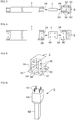
- Fig. 1 is a front view of a waterwheel suspending device 1 of the present invention transversely provided so as to bridge a flume R to suspend waterwheels.
- Fig. 2 is a side view of the waterwheel suspending device 1 with some parts cut.
- the waterwheel suspending device 1 includes a plurality of suspension main bodies 2, holding bodies 3 each fixedly supporting an extremity of the relevant suspension main body 2 at a relevant side of the flume R, footings 5 disposed on opposite banks of the water channel, each of the footings 5 fixedly supporting the relevant holding body 3 at an upper surface thereof, joining elements 4 each joining the relevant suspension main body 2 and the relevant holding body 3, and a floor plate 6 stretched across upper surfaces of the suspension main bodies 2.
- Fig. 3 is a plan view of the suspension main body 2, the holding body 3 and the footing 5 with some parts cut out and Fig. 4 is a front view of the same.
- the suspension main body 2 is, for example, a pipe body having a rectangular sectional shape that is 10 cm wide and 20 cm high and have a length of, for example, 1 m, and a plurality of suspension main bodies 2 can be joined in series via a joining element 4. Also, non-illustrated screw holes for fixing the floor plate 6 are provided in the upper surface of the suspension main body 2. For enhancement in durability, for example, an FRP protection layer is formed on surfaces of the suspension main body 2.
- the joining element 4 is a rectangular block having a size that allows the joining element 4 to be fitted in a pipe hole 2A of the suspension main body 2 and a fitting portion 3A of the holding body 3, and bolt holes 4A corresponding to bolt holes 2B in an end portion of the suspension main body 2 and bolt holes 3D of the holding body 3 are provided in the joining element 4.
- Fig. 5 is a perspective view of the holding body 3.
- a base 3A On an upper surface of a base 3A, horizontal flanges 3C, 3C are provided in a projecting manner in the front and the rear of a lower portion of a cube including a fitting portion 3B formed in a side surface of one side.
- Bolt holes 3D and 3E are provided through front and rear walls of the fitting portion 3A and in the flanges 3C, respectively.
- the footing 5 illustrated in Fig. 6 includes an elongated anchor portion 5B provided in a descending manner on an area on the central side of a lower surface of a cuboidal mount portion 5A including an upper surface having a dimension that is slightly larger than a lower surface of the holding body 3, and is formed of cement concrete and includes non-illustrated reinforcing steel bars buried therein.
- threaded rods 5C, 5C to be fitted in bolt holes 3D in the flanges 3C of the holding body 3 are disposed, and the bolt holes 3D in the flanges 3C of the holding body 3 are fitted to the threaded bolts 5C and fastened to the threaded bolts 5C via nuts.
- the plurality of suspension main bodies 2 can be joined via the joining element 4.
- Fig. 1 two suspension main bodies 2, 2 are joined via the joining element 4.
- the waterwheel suspending device 1 formed as described above can easily be constructed at any of flumes R having different widths under any of different geographical conditions. A method for constructing the waterwheel suspending device 1 will be described below.
- a length of the suspension main bodies 2 is determined so as to be suited to a width of a water channel R, and positions at which holding bodies 3 to which end portions of the suspension main bodies 2 are fixed are determined and a foundation hole 7 that is 20 cm in diameter and 30 cm deep is dug in ground G of the site.
- a bottom of the foundation hole 7 is tamped down and a cement slurry is poured onto the bottoms so as to have a thickness of, for example, around 10 cm to form a concrete bottom slab 8.
- a hard concrete block prepared in advance may be provided.
- the anchor portion 5B of the footing 5 is inserted to, and positioned in, the foundation hole 7, a cement fluid is poured around the anchor portion 5B in the foundation hole 7 with an upper surface of the footing 5 kept horizontally and then is cured into a concrete base 9. Work similar to the above is performed on ground G of the opposite band.
- Fig. 7 is a plan view of the waterwheel suspending device 1 in a state in which the waterwheel suspending device 1 is transversely provided so as to bridge the flume R.
- Two suspension main bodies 2 are arranged in parallel on the upstream side and the downstream side, respectively.
- a space between the suspension main bodies 2 arrange in parallel is set so as to be suited to a size of the waterwheel devices 10 to be installed.
- suspension main bodies 2 can be arranged in parallel to respond to such case.
- the floor plate 6 is screw-fastened to the upper surfaces of the suspension main bodies 2.
- the floor plate 6 may be formed of an arbitrary material such as metal, synthetic resin or wood as long as the floor plate 6 can support the waterwheel devices 10.
- installation holes 6A having a size that enables the waterwheel devices 10 to be inserted into and pulled out therefrom are provided and in the upstream side of the same, holding holes 6B holding suspension pipes 13 for the waterwheel devices 10 are provided.
- a rotor 12 is fixedly provided at a distal end of a non-illustrated rotor shaft supported inside each waterwheel casing 11.
- a suspension pipe 13 is fixed to an upper portion of each waterwheel casing 11 and a power generator 14 is disposed at an upper end of the suspension pipe 13.
- a non-illustrated transmission shaft disposed inside each suspension pipe 13 is joined to the rotor shaft and a rotary shaft of the power generator 14.
- a duct 15 is disposed so as to surround each waterwheel casing 11.
- An inclined portion 12B inclined in the upstream direction is formed at an edge of each lift-type blade 12A of each rotor 12.
- the inclined portion 12B is configured so as to, upon rotation, receive a water flow of water hitting the lift-type blades 12A and thereby scattered in a centrifugal direction to enhance a torque.
- Each duct 15 is fixed to a lower end portion of each suspension pipe 13, and inside the duct 15, the relevant waterwheel casing 11 is safely and firmly fixed and a flow speed inside is enhanced.
- a non-illustrated horizontal sectional shape of each suspension pipe 13 is a fish-like shape in which a front portion is thick and a rear portion is thinner.
- a platelike suspension lock fitting 17 is fixed to a position in an upper position in each suspension pipe 13 at which the suspension pipe 13 is in contact with an upper surface of the floor plate 6.
- Each suspension lock fitting 17 is suspended on, screw-fastened and thereby fixed to a part around the relevant holding hole 6B of the floor plate 6.
- Hooks 17A that hold a towing cable when the relevant waterwheel 10 is lifted up/down 17A are provided at an upper surface of each suspension lock fitting 17.
- a slanted support rod 16 for preventing shaking of the relevant waterwheel casing 11 is fixed between a rear portion of each relevant suspension pipe 13 and a front surface of the relevant suspension main body 2 on the downstream side of the waterwheel suspending device 1.
- Fig. 8 is a perspective view illustrating another embodiment of a holding body 3. Parts that are the same as those of the preceding embodiment are provided with symbols that are the same as those of the preceding embodiment and description thereof will be omitted.
- the holding body 3 in embodiment 2 includes a groove-like fitting portion 3B in which an extremity portion of a suspension main body 2 is to be inserted from above, and thus even if the suspension main body 2 is relatively long, the suspension main body 2 can be fitted and fixed in the fitting portion 3B.
- Fig. 9 is a perspective view illustrating another embodiment of a footing. Parts that are the same as those of the preceding embodiment are provided with symbols that are the same as those of the preceding embodiment and description thereof will be omitted.
- the footing 5 in this embodiment includes a lower portion of an anchor portion 5B, the lower portion being formed so as to be larger than an upper portion, and thus is favorable in stability.
- the footing 5 includes non-illustrated reinforcing steel bars buried inside and thus have high rigidity.
- the holding body 3 or an end portion of the suspension main body 2 can directly be fixed to threaded rods 5C in the upper surface.
- the shape of the suspension main bodies 2 in the present invention is not limited to this shape, and, for example, an H-shaped steel material or a steel material having any of other arbitrary shape can be used, and a joining element of an outer-fitting type, the joining element having a shape conforming to a sectional shape of the steel material, is selected.
- a combination of necessary members is included and a length of a suspension main body can be adjusted, and thus, the waterwheel suspending device can easily be provided so as to bridge a water channel even at any of sites having different water channel widths and thus is excellent in ease of work and can effectively be used in installation of a hydropower generator in, e.g., a flume.
Landscapes
- Engineering & Computer Science (AREA)
- Chemical & Material Sciences (AREA)
- Combustion & Propulsion (AREA)
- Mechanical Engineering (AREA)
- General Engineering & Computer Science (AREA)
- Power Engineering (AREA)
- Hydraulic Turbines (AREA)
- Bridges Or Land Bridges (AREA)
- Supports For Pipes And Cables (AREA)
- Other Liquid Machine Or Engine Such As Wave Power Use (AREA)
Abstract
Description
- The present invention relates to a suspension device for disposing a waterwheel in a water channel and relates to a waterwheel suspending device that enables a waterwheel to be easily disposed in a short period of time in any of water channels having different widths.
- Conventionally,
PTL 1 describes an example in which for disposition of waterwheels in a flume, horizontal beams are transversely provided so as to bridge the flume via locking members arranged on upper surfaces of side walls of a water channel to cause the waterwheels to be supported by the horizontal beams. - [PTL 1]
JP 2015-14219 A - Where locking members such as described in
PTL 1 above are disposed on upper surfaces of side walls of a water channel, since different flumes have different water channel widths, the locking members may fail to be arranged and a length of the horizontal beam needs to be adjusted for each case. - An object of the present invention is to provide a waterwheel suspending device that can be installed in a short period of time regardless of a width of the water channel and is excellent in ease of work and safety.
- Specific contents of the present invention are as follows.
- (1) A waterwheel suspending device that is a suspension support device transversely provided so as to bridge opposite banks of a water channel to suspend a waterwheel, the device comprising a combination of spliceable suspension main bodies arranged in parallel on an upstream side and a downstream side of the water channel, respectively, a plurality of footings for horizontally supporting respective end portions of the suspension main bodies outside the water channel and a floor plate stretched across upper surfaces of the suspension main bodies.
- (2) The waterwheel suspending device according to (1) above, wherein a holding body including a fitting portion that maintains an end portion of the relevant suspension main body horizontally is provided on an upper surface of each of the footings.
- (3) The waterwheel suspending device according to (1) or (2) above, wherein a mount portion for fixing a relevant holding body is formed on an anchor portion of each of the footings.
- (4) The waterwheel suspending device according to any of (1) to (3) above, wherein each of the footings includes a threaded rod provided in an upright manner in an upper surface of a relevant mount portion.
- (5) The waterwheel suspending device according to any of (1) to (4) above, wherein each of the suspension main bodies is configured so that a plurality of suspension main bodies can be joined in series via a joining element.
- The present invention provides the following advantages.
- Since the invention stated in (1) above includes a combination of spliceable suspension main bodies, footings and a floor plate, a waterwheel can easily be disposed in a short period of time in a flume in any geographical condition by merely digging foundation holes in the ground besides a water channel, installing the footings, fixing extremity portions of the suspension main bodies to the footings to cause the suspension main bodies to be transversely provided so as to bridge the footings and stretching the floor plate over the suspension main bodies.
- In the invention according to (2) above, a holding body including a fitting portion that maintains an end portion of the relevant suspension main body horizontally is provided in an upper surface of each of the footings, and thus, the extremity portions of the suspension main bodies can easily and firmly be fixed to the holding bodies by fitting the extremity portions of the suspension main bodies in the holding bodies.
- In the invention according to (3) above, a mount portion for fixing a relevant holding body is formed on an anchor portion of each of the footings, the suspension main bodies can firmly be fixed by burying the anchor portions in the ground and fixing the holding bodies to exposed upper surfaces of the mount portions.
- In the invention according to (4) above, each of the footings includes a threaded bolt provided in an upright manner in an upper surface of a relevant mount portion, and thus, the holding bodies can firmly be fixed by the threaded bolts.
- In the invention according to (5) above, each of the suspension main bodies is configured so that a plurality of suspension main bodies can be joined in series via a joining element, and thus, where the flume has a wide width, suspension main bodies can be joined via a joining element according to the width of the flume and thus can easily be installed.
-
-
Fig. 1 is a vertical front sectional view of an embodiment of the present invention; -
Fig. 2 is a side view ofFig. 1 with some parts cut out; -
Fig. 3 is a plan view of a suspension main body and a holding body inFig. 1 ; -
Fig. 4 is a front view of a suspension main body and a holding body inFig. 3 ; -
Fig. 5 is a perspective view of a holding body inFig. 1 ; -
Fig. 6 is a perspective view of a footing inFig. 1 ; -
Fig. 7 is a plan view of the waterwheel suspending device inFig. 1 transversely provided so as to bridge a water channel; -
Fig. 8 is a perspective view of a holding body according to a second embodiment; and -
Fig. 9 is a perspective view of a footing according to the second embodiment. - Embodiments of the present invention will be described with reference to the drawings.
Fig. 1 is a front view of awaterwheel suspending device 1 of the present invention transversely provided so as to bridge a flume R to suspend waterwheels.Fig. 2 is a side view of thewaterwheel suspending device 1 with some parts cut. - The
waterwheel suspending device 1 includes a plurality of suspensionmain bodies 2,holding bodies 3 each fixedly supporting an extremity of the relevant suspensionmain body 2 at a relevant side of the flume R,footings 5 disposed on opposite banks of the water channel, each of thefootings 5 fixedly supporting therelevant holding body 3 at an upper surface thereof, joiningelements 4 each joining the relevant suspensionmain body 2 and therelevant holding body 3, and afloor plate 6 stretched across upper surfaces of the suspensionmain bodies 2. -
Fig. 3 is a plan view of the suspensionmain body 2, theholding body 3 and thefooting 5 with some parts cut out andFig. 4 is a front view of the same. The suspensionmain body 2 is, for example, a pipe body having a rectangular sectional shape that is 10 cm wide and 20 cm high and have a length of, for example, 1 m, and a plurality of suspensionmain bodies 2 can be joined in series via a joiningelement 4. Also, non-illustrated screw holes for fixing thefloor plate 6 are provided in the upper surface of the suspensionmain body 2. For enhancement in durability, for example, an FRP protection layer is formed on surfaces of the suspensionmain body 2. - The joining
element 4 is a rectangular block having a size that allows the joiningelement 4 to be fitted in apipe hole 2A of the suspensionmain body 2 and afitting portion 3A of theholding body 3, andbolt holes 4A corresponding tobolt holes 2B in an end portion of the suspensionmain body 2 andbolt holes 3D of theholding body 3 are provided in the joiningelement 4. -
Fig. 5 is a perspective view of theholding body 3. On an upper surface of abase 3A,horizontal flanges fitting portion 3B formed in a side surface of one side.Bolt holes fitting portion 3A and in theflanges 3C, respectively. - The
footing 5 illustrated inFig. 6 includes anelongated anchor portion 5B provided in a descending manner on an area on the central side of a lower surface of acuboidal mount portion 5A including an upper surface having a dimension that is slightly larger than a lower surface of theholding body 3, and is formed of cement concrete and includes non-illustrated reinforcing steel bars buried therein. - In the upper surface of the
mount portion 5A, threadedrods bolt holes 3D in theflanges 3C of theholding body 3 are disposed, and thebolt holes 3D in theflanges 3C of theholding body 3 are fitted to the threadedbolts 5C and fastened to the threadedbolts 5C via nuts. - Where the flume R has a wide width, the plurality of suspension
main bodies 2 can be joined via the joiningelement 4. InFig. 1 , two suspensionmain bodies element 4. - The
waterwheel suspending device 1 formed as described above can easily be constructed at any of flumes R having different widths under any of different geographical conditions. A method for constructing thewaterwheel suspending device 1 will be described below. - As illustrated in
Fig. 1 , at a site at whichwaterwheel devices 10 are intended to be installed, a length of the suspensionmain bodies 2 is determined so as to be suited to a width of a water channel R, and positions at which holdingbodies 3 to which end portions of the suspensionmain bodies 2 are fixed are determined and afoundation hole 7 that is 20 cm in diameter and 30 cm deep is dug in ground G of the site. - A bottom of the
foundation hole 7 is tamped down and a cement slurry is poured onto the bottoms so as to have a thickness of, for example, around 10 cm to form aconcrete bottom slab 8. In this case, a hard concrete block prepared in advance may be provided. - Next, the
anchor portion 5B of thefooting 5 is inserted to, and positioned in, thefoundation hole 7, a cement fluid is poured around theanchor portion 5B in thefoundation hole 7 with an upper surface of thefooting 5 kept horizontally and then is cured into aconcrete base 9. Work similar to the above is performed on ground G of the opposite band. - In this case, where the water channel R has a narrow width, as illustrated in
Fig. 1 , a procedure in which the plurality of suspensionmain bodies main bodies holding bodies anchor portions footings respective foundation holes footings holding bodies -
Fig. 7 is a plan view of thewaterwheel suspending device 1 in a state in which thewaterwheel suspending device 1 is transversely provided so as to bridge the flume R. Two suspensionmain bodies 2 are arranged in parallel on the upstream side and the downstream side, respectively. A space between the suspensionmain bodies 2 arrange in parallel is set so as to be suited to a size of thewaterwheel devices 10 to be installed. - Where the
waterwheel devices 10 to be suspended are large in size, three or more suspensionmain bodies 2 can be arranged in parallel to respond to such case. - The
floor plate 6 is screw-fastened to the upper surfaces of the suspensionmain bodies 2. Thefloor plate 6 may be formed of an arbitrary material such as metal, synthetic resin or wood as long as thefloor plate 6 can support thewaterwheel devices 10. In the downstream side of thefloor plate 6,installation holes 6A having a size that enables thewaterwheel devices 10 to be inserted into and pulled out therefrom are provided and in the upstream side of the same, holdingholes 6B holdingsuspension pipes 13 for thewaterwheel devices 10 are provided. - Although the
waterwheel devices 10 illustrated inFigs. 1 and 2 are mere examples, arotor 12 is fixedly provided at a distal end of a non-illustrated rotor shaft supported inside eachwaterwheel casing 11. Asuspension pipe 13 is fixed to an upper portion of eachwaterwheel casing 11 and apower generator 14 is disposed at an upper end of thesuspension pipe 13. - A non-illustrated transmission shaft disposed inside each
suspension pipe 13 is joined to the rotor shaft and a rotary shaft of thepower generator 14. Aduct 15 is disposed so as to surround eachwaterwheel casing 11. - An
inclined portion 12B inclined in the upstream direction is formed at an edge of each lift-type blade 12A of eachrotor 12. - The
inclined portion 12B is configured so as to, upon rotation, receive a water flow of water hitting the lift-type blades 12A and thereby scattered in a centrifugal direction to enhance a torque. - Each
duct 15 is fixed to a lower end portion of eachsuspension pipe 13, and inside theduct 15, therelevant waterwheel casing 11 is safely and firmly fixed and a flow speed inside is enhanced. - A non-illustrated horizontal sectional shape of each
suspension pipe 13 is a fish-like shape in which a front portion is thick and a rear portion is thinner. A platelike suspension lock fitting 17 is fixed to a position in an upper position in eachsuspension pipe 13 at which thesuspension pipe 13 is in contact with an upper surface of thefloor plate 6. Each suspension lock fitting 17 is suspended on, screw-fastened and thereby fixed to a part around therelevant holding hole 6B of thefloor plate 6. -
Hooks 17A that hold a towing cable when therelevant waterwheel 10 is lifted up/down 17A are provided at an upper surface of each suspension lock fitting 17. Also, aslanted support rod 16 for preventing shaking of therelevant waterwheel casing 11 is fixed between a rear portion of eachrelevant suspension pipe 13 and a front surface of the relevant suspensionmain body 2 on the downstream side of thewaterwheel suspending device 1. After thewaterwheel devices 10 are disposed in thewaterwheel suspending device 1, thepower generators 14 are connected to the respective upper ends of thesuspension pipes 13. -
Fig. 8 is a perspective view illustrating another embodiment of a holdingbody 3. Parts that are the same as those of the preceding embodiment are provided with symbols that are the same as those of the preceding embodiment and description thereof will be omitted. The holdingbody 3 inembodiment 2 includes a groove-likefitting portion 3B in which an extremity portion of a suspensionmain body 2 is to be inserted from above, and thus even if the suspensionmain body 2 is relatively long, the suspensionmain body 2 can be fitted and fixed in thefitting portion 3B. -
Fig. 9 is a perspective view illustrating another embodiment of a footing. Parts that are the same as those of the preceding embodiment are provided with symbols that are the same as those of the preceding embodiment and description thereof will be omitted. Thefooting 5 in this embodiment includes a lower portion of ananchor portion 5B, the lower portion being formed so as to be larger than an upper portion, and thus is favorable in stability. Thefooting 5 includes non-illustrated reinforcing steel bars buried inside and thus have high rigidity. - As described above, it is only necessary to form a
concrete bottom slab 8 on the bottom of eachfoundation hole 7, dispose afooting 5 on theconcrete bottom slab 8 and put soil back into thefoundation hole 7 to fill thefoundation hole 7, which is excellent in ease of work. - The holding
body 3 or an end portion of the suspensionmain body 2 can directly be fixed to threadedrods 5C in the upper surface. - Although the suspension
main bodies 2 having a pipe-like shape are shown, the shape of the suspensionmain bodies 2 in the present invention is not limited to this shape, and, for example, an H-shaped steel material or a steel material having any of other arbitrary shape can be used, and a joining element of an outer-fitting type, the joining element having a shape conforming to a sectional shape of the steel material, is selected. - In a waterwheel suspending frame device of the present invention, a combination of necessary members is included and a length of a suspension main body can be adjusted, and thus, the waterwheel suspending device can easily be provided so as to bridge a water channel even at any of sites having different water channel widths and thus is excellent in ease of work and can effectively be used in installation of a hydropower generator in, e.g., a flume.
Claims (5)
- A waterwheel suspending device that is a support device transversely provided so as to bridge a water channel to suspend a waterwheel, the device comprising a combination of spliceable suspension main bodies arranged in parallel on an upstream side and a downstream side of a water channel, respectively, a plurality of footings for horizontally supporting respective end portions of suspension main bodies outside a water channel and a floor plate stretched across upper surfaces of suspension main bodies.
- The waterwheel suspending device according to claim 1, wherein a holding body including a fitting portion that maintains an end portion of a relevant suspension main body horizontally is provided on an upper surface of each of the footings.
- The waterwheel suspending device according to claim 1 or 2, wherein a mount portion for fixing a relevant holding body is formed on an anchor portion of each of the footings.
- The waterwheel suspending device according to any of claims 1 to 3, wherein each of the footings includes a threaded rod provided in an upright manner in an upper surface of a relevant mount portion.
- The waterwheel suspending device according to any of claims 1 to 4, wherein each of the suspension main bodies is configured so that a plurality of suspension main bodies can be joined in series via a joining element.
Applications Claiming Priority (2)
| Application Number | Priority Date | Filing Date | Title |
|---|---|---|---|
| JP2016175166A JP6871698B2 (en) | 2016-09-08 | 2016-09-08 | Water wheel suspension device |
| PCT/JP2017/032382 WO2018047926A1 (en) | 2016-09-08 | 2017-09-07 | Hydraulic turbine suspending device |
Publications (3)
| Publication Number | Publication Date |
|---|---|
| EP3511559A1 true EP3511559A1 (en) | 2019-07-17 |
| EP3511559A4 EP3511559A4 (en) | 2020-02-26 |
| EP3511559B1 EP3511559B1 (en) | 2022-05-04 |
Family
ID=61562852
Family Applications (1)
| Application Number | Title | Priority Date | Filing Date |
|---|---|---|---|
| EP17848864.9A Active EP3511559B1 (en) | 2016-09-08 | 2017-09-07 | Hydraulic turbine suspending device |
Country Status (6)
| Country | Link |
|---|---|
| US (1) | US11053909B2 (en) |
| EP (1) | EP3511559B1 (en) |
| JP (1) | JP6871698B2 (en) |
| KR (1) | KR102335568B1 (en) |
| CN (1) | CN109790815A (en) |
| WO (1) | WO2018047926A1 (en) |
Families Citing this family (3)
| Publication number | Priority date | Publication date | Assignee | Title |
|---|---|---|---|---|
| KR102168769B1 (en) * | 2016-03-22 | 2020-10-22 | 엔티엔 가부시키가이샤 | Water wheel device and hydro power device |
| KR101868973B1 (en) * | 2016-07-28 | 2018-08-09 | 주식회사 서준 | Hydraulic power generating system) |
| WO2018152208A1 (en) * | 2017-02-14 | 2018-08-23 | KNIGHT, Bradford G. | Modular envelope hydrodynamic electrification system |
Family Cites Families (79)
| Publication number | Priority date | Publication date | Assignee | Title |
|---|---|---|---|---|
| US1034603A (en) * | 1911-07-25 | 1912-08-06 | Joseph O Farley | Water-motor. |
| US1399558A (en) * | 1919-01-09 | 1921-12-06 | Olaf L Howe | Water-motor |
| US1555847A (en) * | 1924-03-17 | 1925-10-06 | Hudson Sidney George | Scaffolding clamp |
| US2924311A (en) * | 1957-04-02 | 1960-02-09 | Donn Prod Inc | T-splice |
| US3221466A (en) * | 1964-02-13 | 1965-12-07 | Donn Prod Inc | Dual purpose interlocking beam connectors |
| US3462021A (en) * | 1968-01-29 | 1969-08-19 | Eugene E Hawke | Load-resisting structures made of thin-walled,square tubing and connected with novel square,non-twisting couplings |
| US3584904A (en) * | 1969-03-13 | 1971-06-15 | Flangeklamp Corp | Locking connection for supporting grid systems |
| US3685863A (en) * | 1969-10-30 | 1972-08-22 | Hans Oetiker | Structural elements |
| US3979874A (en) * | 1972-11-24 | 1976-09-14 | Alabama Metal Industries Corporation | Suspended ceiling system and runner joints therefor |
| US3898784A (en) * | 1973-02-20 | 1975-08-12 | Roblin Hope S Ind Inc | Beam splice connection |
| USRE31201E (en) * | 1973-09-14 | 1983-04-12 | Donn Products Incorporated | Locking connection for supporting grid systems |
| US4018020A (en) * | 1973-11-01 | 1977-04-19 | Roblin Industries, Inc. | Modular wall construction |
| US3890760A (en) * | 1974-01-25 | 1975-06-24 | Nat Rolling Mills Co | Main beam joint for suspended ceilings |
| US3928950A (en) * | 1974-05-17 | 1975-12-30 | Preston Metal & Roofing Prod | Structural member with end connector |
| US3921363A (en) * | 1974-05-17 | 1975-11-25 | Preston Metal & Roofing Prod | Cross member with end connector |
| US4161856A (en) * | 1976-11-15 | 1979-07-24 | Donn Products, Inc. | Suspension ceiling system |
| US4241283A (en) * | 1978-09-05 | 1980-12-23 | Storer Richard R Sr | Hydro-electric power plant |
| US4317318A (en) * | 1979-09-04 | 1982-03-02 | Roblin Industries, Inc. | Supporting grid system having interchangeable T sections |
| US4314432A (en) * | 1980-03-17 | 1982-02-09 | Roper Corporation | Splice for beam in suspended ceiling system |
| US4625124A (en) * | 1984-11-13 | 1986-11-25 | Ching An Wu | Sea wave impacted power generating device |
| US4630550A (en) * | 1985-04-02 | 1986-12-23 | Jack J. Weitzman | Prefabricated knock-down metal-frame work table |
| US4738061A (en) * | 1985-04-24 | 1988-04-19 | Herndon Thomas W | Foundation system for manufactured homes |
| US4717831A (en) * | 1985-05-13 | 1988-01-05 | Naomi Kikuchi | Ocean and river power generator |
| US4691818A (en) * | 1986-01-27 | 1987-09-08 | The Laitram Corp. | Concealed drive coupling for use with modular screw conveyor |
| US4843249A (en) * | 1988-08-09 | 1989-06-27 | Bussiere Jean L | Hydroelectric system |
| US5127760A (en) * | 1990-07-26 | 1992-07-07 | Brady Todd A | Vertically slotted header |
| US5226583A (en) * | 1990-08-21 | 1993-07-13 | Ishikawajima-Harima Jukogyo Kabushiki Kaisha | Module frame work for larger structure, method and device for assembling module frame work and coupler for module frame work |
| US5440175A (en) * | 1993-07-06 | 1995-08-08 | Mayo, Jr.; Howard A. | Waterwheel-driven generating unit |
| US5531464A (en) * | 1994-12-09 | 1996-07-02 | Maurer; Raymond N. | Cart with snap-locking members |
| US5596845A (en) * | 1995-05-04 | 1997-01-28 | Strizki; Richard | Adjustable safety breakaway mounting apparatus |
| US5882143A (en) * | 1997-05-19 | 1999-03-16 | Williams, Jr.; Fred Elmore | Low head dam hydroelectric system |
| US6983569B1 (en) * | 1999-08-09 | 2006-01-10 | Zev Rosenberg | Modular metal wall framing system |
| US6408587B2 (en) * | 1999-12-24 | 2002-06-25 | Total Fabrications Limited | Structural members and associated parts |
| US6534881B1 (en) * | 2001-05-25 | 2003-03-18 | Slavcho Slavchev | Waterwheel power generating device |
| US6837016B2 (en) * | 2001-08-30 | 2005-01-04 | Simmons Robert J | Moment-resistant building frame structure componentry and method |
| US6609344B2 (en) * | 2001-11-21 | 2003-08-26 | Eluterio Saldana | Connectors, tracks and system for smooth-faced metal framing |
| US7007431B2 (en) * | 2003-05-09 | 2006-03-07 | Nci Building Systems, Lp | Multi-story building and method for construction thereof |
| US6874971B2 (en) * | 2003-07-08 | 2005-04-05 | Freeman Capital Company | Connector for tube and connected tubular structure |
| US20050034408A1 (en) * | 2003-07-30 | 2005-02-17 | Joseph Palumbo | Metal stud wall packaging system |
| US20060283130A1 (en) * | 2005-06-07 | 2006-12-21 | William Andrews | Structural members with gripping features and joining arrangements therefor |
| US20060277841A1 (en) * | 2005-06-09 | 2006-12-14 | Majusiak Frederick J | Track member for wall and soffit construction |
| JP2007040217A (en) * | 2005-08-04 | 2007-02-15 | Kaiyo Bokujo:Kk | Hydraulic power generation device |
| US7594331B2 (en) * | 2005-11-05 | 2009-09-29 | Wiltin Pty. Ltd. | Method of production of joining profiles for structural members |
| JP2007211651A (en) * | 2006-02-08 | 2007-08-23 | Yoshimoto Pole Co Ltd | Power generating device |
| GB2443823B (en) * | 2007-04-12 | 2008-11-12 | Denmay Steel | Devices and methods for use in construction |
| JP4157590B1 (en) * | 2007-11-20 | 2008-10-01 | 株式会社シグナスミル | Simple installation type hydroelectric generator |
| CN102575637A (en) * | 2009-07-21 | 2012-07-11 | 生态技术株式会社 | Hydroelectric power generating equipment |
| WO2011123966A1 (en) * | 2010-04-05 | 2011-10-13 | Ivan Dib Echeverria | Marine energy capture system |
| US20160017558A1 (en) * | 2010-04-23 | 2016-01-21 | French Development Enterprises, LLC | Aquatic Animal Passage With Counter |
| US10760233B2 (en) * | 2010-04-23 | 2020-09-01 | French Development Enterprises, LLC | Precast dam structure with flowpath |
| US9103084B2 (en) * | 2010-04-23 | 2015-08-11 | French Development Enterprises, LLC | Intelligent hydroelectric dam with power storage |
| US20120007361A1 (en) * | 2010-07-09 | 2012-01-12 | Pete Agtuca | Water Handling Environment Water Electric Generator |
| US20120032444A1 (en) * | 2010-08-06 | 2012-02-09 | John Alan Burton | Wave Catcher |
| WO2012039667A1 (en) * | 2010-09-24 | 2012-03-29 | Mohamed Sahbi Belarbi | Energy generation system including pontoon unit and water wheel |
| US8786122B2 (en) * | 2011-07-27 | 2014-07-22 | Dlz Corporation | Horizontal-axis hydrokinetic water turbine system with water pump |
| JP5804884B2 (en) * | 2011-10-06 | 2015-11-04 | 株式会社渡会電気土木 | Hydroelectric generator |
| US20130088013A1 (en) * | 2011-10-11 | 2013-04-11 | Moshe J. Yan | Water current energy converter system |
| US8863511B2 (en) * | 2012-03-24 | 2014-10-21 | Paul M Swamidass | Wave and water energy converter mounted on bridge supports |
| GB2509353B (en) * | 2012-05-14 | 2015-11-11 | Sustainable Marine Energy Ltd | A flowing-water drivable turbine assembly |
| BE1021091B1 (en) * | 2012-10-11 | 2015-11-27 | VAN ROMPAY BOUDEWIJN GABRIëL | DEVICE FOR GENERATING HYDRO-ELECTRIC ENERGY |
| JP2015014219A (en) | 2013-07-03 | 2015-01-22 | 株式会社東芝 | Axial flow water turbine power generation facility |
| US10053833B2 (en) * | 2014-01-24 | 2018-08-21 | Eco Concrete Solutions, Inc. | Pre-cast decorative retaining wall system |
| JP5918291B2 (en) * | 2014-03-24 | 2016-05-18 | 日本システム企画株式会社 | Turbine blade type generator |
| US20150377414A1 (en) * | 2014-06-26 | 2015-12-31 | Alex Parsa Pirseyedi | Modular frame assembly |
| JP2016061183A (en) * | 2014-09-16 | 2016-04-25 | 株式会社春原設計 | Channel type hydraulic power generation device |
| TWI659155B (en) * | 2014-11-11 | 2019-05-11 | 黃國彰 | Power generation device suitable for ocean current |
| US9732725B2 (en) * | 2014-11-13 | 2017-08-15 | Jerome A. Bauer | Automatic height adjusting paddle wheel |
| US10267011B2 (en) * | 2015-01-23 | 2019-04-23 | Eco Concrete Solutions, Inc. | Pre-cast decorative retaining wall system |
| JP6496155B2 (en) * | 2015-02-03 | 2019-04-03 | Thk株式会社 | Hydroelectric generator |
| CN105351143B (en) * | 2015-11-30 | 2018-01-23 | 张文庆 | A kind of marine tidal-current energy power station |
| US20170233996A1 (en) * | 2016-02-16 | 2017-08-17 | Bull Moose Tube Company | Connectors and methods of fabricating the same |
| KR102168769B1 (en) * | 2016-03-22 | 2020-10-22 | 엔티엔 가부시키가이샤 | Water wheel device and hydro power device |
| CN108884806B (en) * | 2016-03-22 | 2020-12-29 | Ntn株式会社 | Water turbine, connection structure of two male threaded shafts for use in water turbine, and connection structure of two shafts |
| EP3472399A4 (en) * | 2016-06-19 | 2019-07-17 | Marcel Eric Morokutti | APPARATUS AND METHOD FOR CONSTRUCTION |
| US10281097B2 (en) * | 2017-04-26 | 2019-05-07 | Habitex Corporation | Floor lamp and support rod assembly thereof |
| US10344489B2 (en) * | 2017-05-10 | 2019-07-09 | Western Sulfur Remelters Ltd. | Adjustable support column with uplift-resisting assembly |
| WO2019161217A1 (en) * | 2018-02-17 | 2019-08-22 | BuildXGroup, Inc. | Cube coupling joint |
| US10508432B2 (en) * | 2018-04-24 | 2019-12-17 | Ss-20 Building Systems, Inc. | Connection for stacking post system for multistory building construction |
| US10745901B2 (en) * | 2018-11-21 | 2020-08-18 | Steel Worx Solutions LLC | System and method of constructing a multi-story building utilizing modular components |
-
2016
- 2016-09-08 JP JP2016175166A patent/JP6871698B2/en active Active
-
2017
- 2017-09-07 EP EP17848864.9A patent/EP3511559B1/en active Active
- 2017-09-07 CN CN201780055290.1A patent/CN109790815A/en active Pending
- 2017-09-07 US US16/330,780 patent/US11053909B2/en not_active Expired - Fee Related
- 2017-09-07 KR KR1020197009318A patent/KR102335568B1/en active Active
- 2017-09-07 WO PCT/JP2017/032382 patent/WO2018047926A1/en not_active Ceased
Also Published As
| Publication number | Publication date |
|---|---|
| WO2018047926A1 (en) | 2018-03-15 |
| EP3511559B1 (en) | 2022-05-04 |
| JP6871698B2 (en) | 2021-05-12 |
| KR102335568B1 (en) | 2021-12-06 |
| US11053909B2 (en) | 2021-07-06 |
| US20190195187A1 (en) | 2019-06-27 |
| EP3511559A4 (en) | 2020-02-26 |
| CN109790815A (en) | 2019-05-21 |
| JP2018040299A (en) | 2018-03-15 |
| KR20190046928A (en) | 2019-05-07 |
Similar Documents
| Publication | Publication Date | Title |
|---|---|---|
| JP2021510793A (en) | Multi-wind turbines for wind and solar power and floating platforms that self-align against the wind supporting solar, and how to build them | |
| EP3511559B1 (en) | Hydraulic turbine suspending device | |
| KR20110121567A (en) | Foundation interfaces for concrete foundations, wind turbine systems and methods of making concrete foundations | |
| JP2010037798A (en) | Multiple span continuous concrete bridge | |
| JP7118473B1 (en) | Method for constructing bottom-mounted offshore mounting system, bottom-mounted offshore mounting system, and offshore wind power generator | |
| JP2009008567A (en) | River flow measurement system | |
| JP6572469B1 (en) | Concrete foundation structure and its construction method | |
| JP2018178429A (en) | Construction method of steel pipe and sheet pile well foundation and steel pipe and pile pipe foundation | |
| KR200452944Y1 (en) | Butlers Dam | |
| KR20150004038U (en) | Basic prop for the solar-power system | |
| JP2000144677A (en) | Temporary deadline method | |
| CN203977414U (en) | Novel spiral stake | |
| KR200162028Y1 (en) | Formwork for Earthwalls | |
| CN221989137U (en) | A debris flow protection structure | |
| CN206723592U (en) | For protecting the structural member of submerged pipeline | |
| GB2462090A (en) | A mast foundation with a plate and rods around a tube. | |
| JP7672569B1 (en) | Installation structure of driftwood capture body and driftwood capture work | |
| CN110593590B (en) | In-situ protection method for existing high-voltage line pole in deep foundation pit excavation area | |
| RU190430U1 (en) | DEVICE FOR INCREASING STABILITY OF VERTICAL STRUCTURE TO HORIZONTAL LOADS | |
| CN203701116U (en) | Formwork structure for underwater concrete diaphragm wall cofferdam of bridge foundation | |
| CN103322312B (en) | A kind of oil platform pipeline sheath | |
| KR20130033762A (en) | Signage structure with pile foundation | |
| JP3196179U (en) | Jellyfish inflow prevention net expansion device | |
| CN202644570U (en) | H-shaped retaining wall structure | |
| RU125210U1 (en) | FOUNDATION FOR FIXING UZKOBAZOVYH CARRIER DESIGNS |
Legal Events
| Date | Code | Title | Description |
|---|---|---|---|
| STAA | Information on the status of an ep patent application or granted ep patent |
Free format text: STATUS: THE INTERNATIONAL PUBLICATION HAS BEEN MADE |
|
| PUAI | Public reference made under article 153(3) epc to a published international application that has entered the european phase |
Free format text: ORIGINAL CODE: 0009012 |
|
| STAA | Information on the status of an ep patent application or granted ep patent |
Free format text: STATUS: REQUEST FOR EXAMINATION WAS MADE |
|
| 17P | Request for examination filed |
Effective date: 20190405 |
|
| AK | Designated contracting states |
Kind code of ref document: A1 Designated state(s): AL AT BE BG CH CY CZ DE DK EE ES FI FR GB GR HR HU IE IS IT LI LT LU LV MC MK MT NL NO PL PT RO RS SE SI SK SM TR |
|
| AX | Request for extension of the european patent |
Extension state: BA ME |
|
| DAV | Request for validation of the european patent (deleted) | ||
| DAX | Request for extension of the european patent (deleted) | ||
| A4 | Supplementary search report drawn up and despatched |
Effective date: 20200124 |
|
| RIC1 | Information provided on ipc code assigned before grant |
Ipc: F03B 17/06 20060101ALI20200120BHEP Ipc: F03B 11/00 20060101AFI20200120BHEP |
|
| STAA | Information on the status of an ep patent application or granted ep patent |
Free format text: STATUS: EXAMINATION IS IN PROGRESS |
|
| 17Q | First examination report despatched |
Effective date: 20201006 |
|
| GRAP | Despatch of communication of intention to grant a patent |
Free format text: ORIGINAL CODE: EPIDOSNIGR1 |
|
| STAA | Information on the status of an ep patent application or granted ep patent |
Free format text: STATUS: GRANT OF PATENT IS INTENDED |
|
| INTG | Intention to grant announced |
Effective date: 20220111 |
|
| GRAS | Grant fee paid |
Free format text: ORIGINAL CODE: EPIDOSNIGR3 |
|
| GRAA | (expected) grant |
Free format text: ORIGINAL CODE: 0009210 |
|
| STAA | Information on the status of an ep patent application or granted ep patent |
Free format text: STATUS: THE PATENT HAS BEEN GRANTED |
|
| AK | Designated contracting states |
Kind code of ref document: B1 Designated state(s): AL AT BE BG CH CY CZ DE DK EE ES FI FR GB GR HR HU IE IS IT LI LT LU LV MC MK MT NL NO PL PT RO RS SE SI SK SM TR |
|
| REG | Reference to a national code |
Ref country code: GB Ref legal event code: FG4D |
|
| REG | Reference to a national code |
Ref country code: CH Ref legal event code: EP |
|
| REG | Reference to a national code |
Ref country code: AT Ref legal event code: REF Ref document number: 1489290 Country of ref document: AT Kind code of ref document: T Effective date: 20220515 |
|
| REG | Reference to a national code |
Ref country code: IE Ref legal event code: FG4D Ref country code: DE Ref legal event code: R096 Ref document number: 602017057083 Country of ref document: DE |
|
| REG | Reference to a national code |
Ref country code: LT Ref legal event code: MG9D |
|
| REG | Reference to a national code |
Ref country code: NL Ref legal event code: MP Effective date: 20220504 |
|
| REG | Reference to a national code |
Ref country code: AT Ref legal event code: MK05 Ref document number: 1489290 Country of ref document: AT Kind code of ref document: T Effective date: 20220504 |
|
| PG25 | Lapsed in a contracting state [announced via postgrant information from national office to epo] |
Ref country code: SE Free format text: LAPSE BECAUSE OF FAILURE TO SUBMIT A TRANSLATION OF THE DESCRIPTION OR TO PAY THE FEE WITHIN THE PRESCRIBED TIME-LIMIT Effective date: 20220504 Ref country code: PT Free format text: LAPSE BECAUSE OF FAILURE TO SUBMIT A TRANSLATION OF THE DESCRIPTION OR TO PAY THE FEE WITHIN THE PRESCRIBED TIME-LIMIT Effective date: 20220905 Ref country code: NO Free format text: LAPSE BECAUSE OF FAILURE TO SUBMIT A TRANSLATION OF THE DESCRIPTION OR TO PAY THE FEE WITHIN THE PRESCRIBED TIME-LIMIT Effective date: 20220804 Ref country code: NL Free format text: LAPSE BECAUSE OF FAILURE TO SUBMIT A TRANSLATION OF THE DESCRIPTION OR TO PAY THE FEE WITHIN THE PRESCRIBED TIME-LIMIT Effective date: 20220504 Ref country code: LT Free format text: LAPSE BECAUSE OF FAILURE TO SUBMIT A TRANSLATION OF THE DESCRIPTION OR TO PAY THE FEE WITHIN THE PRESCRIBED TIME-LIMIT Effective date: 20220504 Ref country code: HR Free format text: LAPSE BECAUSE OF FAILURE TO SUBMIT A TRANSLATION OF THE DESCRIPTION OR TO PAY THE FEE WITHIN THE PRESCRIBED TIME-LIMIT Effective date: 20220504 Ref country code: GR Free format text: LAPSE BECAUSE OF FAILURE TO SUBMIT A TRANSLATION OF THE DESCRIPTION OR TO PAY THE FEE WITHIN THE PRESCRIBED TIME-LIMIT Effective date: 20220805 Ref country code: FI Free format text: LAPSE BECAUSE OF FAILURE TO SUBMIT A TRANSLATION OF THE DESCRIPTION OR TO PAY THE FEE WITHIN THE PRESCRIBED TIME-LIMIT Effective date: 20220504 Ref country code: ES Free format text: LAPSE BECAUSE OF FAILURE TO SUBMIT A TRANSLATION OF THE DESCRIPTION OR TO PAY THE FEE WITHIN THE PRESCRIBED TIME-LIMIT Effective date: 20220504 Ref country code: BG Free format text: LAPSE BECAUSE OF FAILURE TO SUBMIT A TRANSLATION OF THE DESCRIPTION OR TO PAY THE FEE WITHIN THE PRESCRIBED TIME-LIMIT Effective date: 20220804 Ref country code: AT Free format text: LAPSE BECAUSE OF FAILURE TO SUBMIT A TRANSLATION OF THE DESCRIPTION OR TO PAY THE FEE WITHIN THE PRESCRIBED TIME-LIMIT Effective date: 20220504 |
|
| PG25 | Lapsed in a contracting state [announced via postgrant information from national office to epo] |
Ref country code: RS Free format text: LAPSE BECAUSE OF FAILURE TO SUBMIT A TRANSLATION OF THE DESCRIPTION OR TO PAY THE FEE WITHIN THE PRESCRIBED TIME-LIMIT Effective date: 20220504 Ref country code: PL Free format text: LAPSE BECAUSE OF FAILURE TO SUBMIT A TRANSLATION OF THE DESCRIPTION OR TO PAY THE FEE WITHIN THE PRESCRIBED TIME-LIMIT Effective date: 20220504 Ref country code: LV Free format text: LAPSE BECAUSE OF FAILURE TO SUBMIT A TRANSLATION OF THE DESCRIPTION OR TO PAY THE FEE WITHIN THE PRESCRIBED TIME-LIMIT Effective date: 20220504 Ref country code: IS Free format text: LAPSE BECAUSE OF FAILURE TO SUBMIT A TRANSLATION OF THE DESCRIPTION OR TO PAY THE FEE WITHIN THE PRESCRIBED TIME-LIMIT Effective date: 20220904 |
|
| PG25 | Lapsed in a contracting state [announced via postgrant information from national office to epo] |
Ref country code: SM Free format text: LAPSE BECAUSE OF FAILURE TO SUBMIT A TRANSLATION OF THE DESCRIPTION OR TO PAY THE FEE WITHIN THE PRESCRIBED TIME-LIMIT Effective date: 20220504 Ref country code: SK Free format text: LAPSE BECAUSE OF FAILURE TO SUBMIT A TRANSLATION OF THE DESCRIPTION OR TO PAY THE FEE WITHIN THE PRESCRIBED TIME-LIMIT Effective date: 20220504 Ref country code: RO Free format text: LAPSE BECAUSE OF FAILURE TO SUBMIT A TRANSLATION OF THE DESCRIPTION OR TO PAY THE FEE WITHIN THE PRESCRIBED TIME-LIMIT Effective date: 20220504 Ref country code: EE Free format text: LAPSE BECAUSE OF FAILURE TO SUBMIT A TRANSLATION OF THE DESCRIPTION OR TO PAY THE FEE WITHIN THE PRESCRIBED TIME-LIMIT Effective date: 20220504 Ref country code: DK Free format text: LAPSE BECAUSE OF FAILURE TO SUBMIT A TRANSLATION OF THE DESCRIPTION OR TO PAY THE FEE WITHIN THE PRESCRIBED TIME-LIMIT Effective date: 20220504 Ref country code: CZ Free format text: LAPSE BECAUSE OF FAILURE TO SUBMIT A TRANSLATION OF THE DESCRIPTION OR TO PAY THE FEE WITHIN THE PRESCRIBED TIME-LIMIT Effective date: 20220504 |
|
| REG | Reference to a national code |
Ref country code: DE Ref legal event code: R097 Ref document number: 602017057083 Country of ref document: DE |
|
| PLBE | No opposition filed within time limit |
Free format text: ORIGINAL CODE: 0009261 |
|
| STAA | Information on the status of an ep patent application or granted ep patent |
Free format text: STATUS: NO OPPOSITION FILED WITHIN TIME LIMIT |
|
| PG25 | Lapsed in a contracting state [announced via postgrant information from national office to epo] |
Ref country code: AL Free format text: LAPSE BECAUSE OF FAILURE TO SUBMIT A TRANSLATION OF THE DESCRIPTION OR TO PAY THE FEE WITHIN THE PRESCRIBED TIME-LIMIT Effective date: 20220504 |
|
| REG | Reference to a national code |
Ref country code: DE Ref legal event code: R119 Ref document number: 602017057083 Country of ref document: DE |
|
| 26N | No opposition filed |
Effective date: 20230207 |
|
| PG25 | Lapsed in a contracting state [announced via postgrant information from national office to epo] |
Ref country code: MC Free format text: LAPSE BECAUSE OF FAILURE TO SUBMIT A TRANSLATION OF THE DESCRIPTION OR TO PAY THE FEE WITHIN THE PRESCRIBED TIME-LIMIT Effective date: 20220504 |
|
| REG | Reference to a national code |
Ref country code: CH Ref legal event code: PL |
|
| GBPC | Gb: european patent ceased through non-payment of renewal fee |
Effective date: 20220907 |
|
| REG | Reference to a national code |
Ref country code: BE Ref legal event code: MM Effective date: 20220930 |
|
| PG25 | Lapsed in a contracting state [announced via postgrant information from national office to epo] |
Ref country code: SI Free format text: LAPSE BECAUSE OF FAILURE TO SUBMIT A TRANSLATION OF THE DESCRIPTION OR TO PAY THE FEE WITHIN THE PRESCRIBED TIME-LIMIT Effective date: 20220504 |
|
| PG25 | Lapsed in a contracting state [announced via postgrant information from national office to epo] |
Ref country code: LU Free format text: LAPSE BECAUSE OF NON-PAYMENT OF DUE FEES Effective date: 20220907 |
|
| PG25 | Lapsed in a contracting state [announced via postgrant information from national office to epo] |
Ref country code: LI Free format text: LAPSE BECAUSE OF NON-PAYMENT OF DUE FEES Effective date: 20220930 Ref country code: IE Free format text: LAPSE BECAUSE OF NON-PAYMENT OF DUE FEES Effective date: 20220907 Ref country code: DE Free format text: LAPSE BECAUSE OF NON-PAYMENT OF DUE FEES Effective date: 20230401 Ref country code: CH Free format text: LAPSE BECAUSE OF NON-PAYMENT OF DUE FEES Effective date: 20220930 |
|
| PG25 | Lapsed in a contracting state [announced via postgrant information from national office to epo] |
Ref country code: BE Free format text: LAPSE BECAUSE OF NON-PAYMENT OF DUE FEES Effective date: 20220930 |
|
| PG25 | Lapsed in a contracting state [announced via postgrant information from national office to epo] |
Ref country code: GB Free format text: LAPSE BECAUSE OF NON-PAYMENT OF DUE FEES Effective date: 20220907 |
|
| PG25 | Lapsed in a contracting state [announced via postgrant information from national office to epo] |
Ref country code: IT Free format text: LAPSE BECAUSE OF FAILURE TO SUBMIT A TRANSLATION OF THE DESCRIPTION OR TO PAY THE FEE WITHIN THE PRESCRIBED TIME-LIMIT Effective date: 20220504 |
|
| PG25 | Lapsed in a contracting state [announced via postgrant information from national office to epo] |
Ref country code: HU Free format text: LAPSE BECAUSE OF FAILURE TO SUBMIT A TRANSLATION OF THE DESCRIPTION OR TO PAY THE FEE WITHIN THE PRESCRIBED TIME-LIMIT; INVALID AB INITIO Effective date: 20170907 |
|
| PG25 | Lapsed in a contracting state [announced via postgrant information from national office to epo] |
Ref country code: CY Free format text: LAPSE BECAUSE OF FAILURE TO SUBMIT A TRANSLATION OF THE DESCRIPTION OR TO PAY THE FEE WITHIN THE PRESCRIBED TIME-LIMIT Effective date: 20220504 |
|
| PG25 | Lapsed in a contracting state [announced via postgrant information from national office to epo] |
Ref country code: MK Free format text: LAPSE BECAUSE OF FAILURE TO SUBMIT A TRANSLATION OF THE DESCRIPTION OR TO PAY THE FEE WITHIN THE PRESCRIBED TIME-LIMIT Effective date: 20220504 |
|
| PG25 | Lapsed in a contracting state [announced via postgrant information from national office to epo] |
Ref country code: TR Free format text: LAPSE BECAUSE OF FAILURE TO SUBMIT A TRANSLATION OF THE DESCRIPTION OR TO PAY THE FEE WITHIN THE PRESCRIBED TIME-LIMIT Effective date: 20220504 |
|
| PG25 | Lapsed in a contracting state [announced via postgrant information from national office to epo] |
Ref country code: MT Free format text: LAPSE BECAUSE OF FAILURE TO SUBMIT A TRANSLATION OF THE DESCRIPTION OR TO PAY THE FEE WITHIN THE PRESCRIBED TIME-LIMIT Effective date: 20220504 |
|
| PG25 | Lapsed in a contracting state [announced via postgrant information from national office to epo] |
Ref country code: BG Free format text: LAPSE BECAUSE OF FAILURE TO SUBMIT A TRANSLATION OF THE DESCRIPTION OR TO PAY THE FEE WITHIN THE PRESCRIBED TIME-LIMIT Effective date: 20220504 |
|
| PG25 | Lapsed in a contracting state [announced via postgrant information from national office to epo] |
Ref country code: BG Free format text: LAPSE BECAUSE OF FAILURE TO SUBMIT A TRANSLATION OF THE DESCRIPTION OR TO PAY THE FEE WITHIN THE PRESCRIBED TIME-LIMIT Effective date: 20220504 |
|
| PGFP | Annual fee paid to national office [announced via postgrant information from national office to epo] |
Ref country code: FR Payment date: 20250808 Year of fee payment: 9 |