EP3511523A1 - Impingement cooling arrangement for airfoils - Google Patents
Impingement cooling arrangement for airfoils Download PDFInfo
- Publication number
- EP3511523A1 EP3511523A1 EP19150752.4A EP19150752A EP3511523A1 EP 3511523 A1 EP3511523 A1 EP 3511523A1 EP 19150752 A EP19150752 A EP 19150752A EP 3511523 A1 EP3511523 A1 EP 3511523A1
- Authority
- EP
- European Patent Office
- Prior art keywords
- airfoil
- cavity
- passage
- impingement cavity
- impingement
- Prior art date
- Legal status (The legal status is an assumption and is not a legal conclusion. Google has not performed a legal analysis and makes no representation as to the accuracy of the status listed.)
- Granted
Links
Images





Classifications
-
- F—MECHANICAL ENGINEERING; LIGHTING; HEATING; WEAPONS; BLASTING
- F01—MACHINES OR ENGINES IN GENERAL; ENGINE PLANTS IN GENERAL; STEAM ENGINES
- F01D—NON-POSITIVE DISPLACEMENT MACHINES OR ENGINES, e.g. STEAM TURBINES
- F01D5/00—Blades; Blade-carrying members; Heating, heat-insulating, cooling or antivibration means on the blades or the members
- F01D5/12—Blades
- F01D5/14—Form or construction
- F01D5/18—Hollow blades, i.e. blades with cooling or heating channels or cavities; Heating, heat-insulating or cooling means on blades
- F01D5/186—Film cooling
-
- F—MECHANICAL ENGINEERING; LIGHTING; HEATING; WEAPONS; BLASTING
- F01—MACHINES OR ENGINES IN GENERAL; ENGINE PLANTS IN GENERAL; STEAM ENGINES
- F01D—NON-POSITIVE DISPLACEMENT MACHINES OR ENGINES, e.g. STEAM TURBINES
- F01D5/00—Blades; Blade-carrying members; Heating, heat-insulating, cooling or antivibration means on the blades or the members
- F01D5/12—Blades
- F01D5/14—Form or construction
- F01D5/18—Hollow blades, i.e. blades with cooling or heating channels or cavities; Heating, heat-insulating or cooling means on blades
- F01D5/187—Convection cooling
-
- F—MECHANICAL ENGINEERING; LIGHTING; HEATING; WEAPONS; BLASTING
- F04—POSITIVE - DISPLACEMENT MACHINES FOR LIQUIDS; PUMPS FOR LIQUIDS OR ELASTIC FLUIDS
- F04D—NON-POSITIVE-DISPLACEMENT PUMPS
- F04D29/00—Details, component parts, or accessories
- F04D29/26—Rotors specially for elastic fluids
- F04D29/32—Rotors specially for elastic fluids for axial flow pumps
- F04D29/321—Rotors specially for elastic fluids for axial flow pumps for axial flow compressors
- F04D29/324—Blades
-
- F—MECHANICAL ENGINEERING; LIGHTING; HEATING; WEAPONS; BLASTING
- F04—POSITIVE - DISPLACEMENT MACHINES FOR LIQUIDS; PUMPS FOR LIQUIDS OR ELASTIC FLUIDS
- F04D—NON-POSITIVE-DISPLACEMENT PUMPS
- F04D29/00—Details, component parts, or accessories
- F04D29/58—Cooling; Heating; Diminishing heat transfer
- F04D29/582—Cooling; Heating; Diminishing heat transfer specially adapted for elastic fluid pumps
-
- F—MECHANICAL ENGINEERING; LIGHTING; HEATING; WEAPONS; BLASTING
- F05—INDEXING SCHEMES RELATING TO ENGINES OR PUMPS IN VARIOUS SUBCLASSES OF CLASSES F01-F04
- F05D—INDEXING SCHEME FOR ASPECTS RELATING TO NON-POSITIVE-DISPLACEMENT MACHINES OR ENGINES, GAS-TURBINES OR JET-PROPULSION PLANTS
- F05D2220/00—Application
- F05D2220/30—Application in turbines
- F05D2220/32—Application in turbines in gas turbines
-
- F—MECHANICAL ENGINEERING; LIGHTING; HEATING; WEAPONS; BLASTING
- F05—INDEXING SCHEMES RELATING TO ENGINES OR PUMPS IN VARIOUS SUBCLASSES OF CLASSES F01-F04
- F05D—INDEXING SCHEME FOR ASPECTS RELATING TO NON-POSITIVE-DISPLACEMENT MACHINES OR ENGINES, GAS-TURBINES OR JET-PROPULSION PLANTS
- F05D2240/00—Components
- F05D2240/20—Rotors
- F05D2240/30—Characteristics of rotor blades, i.e. of any element transforming dynamic fluid energy to or from rotational energy and being attached to a rotor
- F05D2240/303—Characteristics of rotor blades, i.e. of any element transforming dynamic fluid energy to or from rotational energy and being attached to a rotor related to the leading edge of a rotor blade
-
- F—MECHANICAL ENGINEERING; LIGHTING; HEATING; WEAPONS; BLASTING
- F05—INDEXING SCHEMES RELATING TO ENGINES OR PUMPS IN VARIOUS SUBCLASSES OF CLASSES F01-F04
- F05D—INDEXING SCHEME FOR ASPECTS RELATING TO NON-POSITIVE-DISPLACEMENT MACHINES OR ENGINES, GAS-TURBINES OR JET-PROPULSION PLANTS
- F05D2260/00—Function
- F05D2260/20—Heat transfer, e.g. cooling
- F05D2260/201—Heat transfer, e.g. cooling by impingement of a fluid
-
- F—MECHANICAL ENGINEERING; LIGHTING; HEATING; WEAPONS; BLASTING
- F05—INDEXING SCHEMES RELATING TO ENGINES OR PUMPS IN VARIOUS SUBCLASSES OF CLASSES F01-F04
- F05D—INDEXING SCHEME FOR ASPECTS RELATING TO NON-POSITIVE-DISPLACEMENT MACHINES OR ENGINES, GAS-TURBINES OR JET-PROPULSION PLANTS
- F05D2260/00—Function
- F05D2260/20—Heat transfer, e.g. cooling
- F05D2260/202—Heat transfer, e.g. cooling by film cooling
-
- Y—GENERAL TAGGING OF NEW TECHNOLOGICAL DEVELOPMENTS; GENERAL TAGGING OF CROSS-SECTIONAL TECHNOLOGIES SPANNING OVER SEVERAL SECTIONS OF THE IPC; TECHNICAL SUBJECTS COVERED BY FORMER USPC CROSS-REFERENCE ART COLLECTIONS [XRACs] AND DIGESTS
- Y02—TECHNOLOGIES OR APPLICATIONS FOR MITIGATION OR ADAPTATION AGAINST CLIMATE CHANGE
- Y02T—CLIMATE CHANGE MITIGATION TECHNOLOGIES RELATED TO TRANSPORTATION
- Y02T50/00—Aeronautics or air transport
- Y02T50/60—Efficient propulsion technologies, e.g. for aircraft
Definitions
- This disclosure relates to cooling for a component of a gas turbine engine, including a component having one or more impingement cooling features.
- Gas turbine engines can include a fan for propulsion air and to cool components.
- the fan also delivers air into an engine core where it is compressed.
- the compressed air is then delivered into a combustion section, where it is mixed with fuel and ignited.
- the combustion gas expands downstream and drives turbine blades.
- Static vanes are positioned adjacent to the turbine blades to control the flow of the products of combustion. The blades and vanes are subject to extreme heat, and thus cooling schemes are utilized for each.
- An airfoil for a gas turbine engine includes an airfoil section that has an internal wall and an external wall.
- the external wall defines pressure and suction sides that extends in a chordwise direction between a leading edge and a trailing edge, a first impingement cavity and a second impingement cavity bounded by the external wall at a leading edge region that defines the leading edge, a first feeding cavity separated from the first impingement cavity and from the second impingement cavity by the internal wall, and a first crossover passage within the internal wall that connects the first impingement cavity and the first feeding cavity.
- the first crossover passage defines a first passage axis that intersects a surface of the first impingement cavity.
- a second crossover passage within the internal wall connects to the second impingement cavity.
- the second crossover passage defines a second passage axis that intersects a surface of the second impingement cavity.
- the second crossover passage connects the second impingement cavity and a second feeding cavity.
- the second feeding cavity separates from the first impingement cavity and from the second impingement cavity by the internal wall.
- the first passage axis intersects the surface of the first impingement cavity adjacent to the pressure side
- the second passage axis intersects the surface of the second impingement cavity adjacent to the suction side
- the first crossover passage extends between a first inlet and a first outlet.
- the second crossover passage extends between a second inlet and a second outlet, and the first inlet is forward of the second outlet with respect to the chordwise direction.
- the second crossover passage connects the second impingement cavity and the first feeding cavity, and the first outlet is forward of the second inlet with respect to the chordwise direction.
- the first impingement cavity defines a first volume and the second impingement cavity defines a second volume that is less than the first volume.
- the airfoil section extends in a spanwise direction from a 0% span position to a 100% span position, and each of an outlet of the first crossover passage and an outlet of the second crossover passage is defined at a span position that is between an 70% span position and the 100% span position.
- the airfoil is a high lift airfoil.
- the airfoil is a turbine blade.
- the airfoil section defines a mean camber line extending between the leading and trailing edges to bisect a thickness of the airfoil section, and a rib separating the first impingement cavity and the second impingement cavity being transverse to the mean camber line.
- the first passage axis intersects the external wall at an intersection point.
- the intersection point is between the trailing edge and a gauge point defined by the airfoil.
- a core for an airfoil includes a first portion that corresponds to a first impingement cavity of a leading edge region of an airfoil, a second portion that corresponds to a second impingement cavity of the leading edge region of the airfoil, a third portion that corresponds to a first feeding cavity of the airfoil, and a fourth portion that corresponds to a second feeding cavity of the airfoil.
- a first set of connectors couple the first portion and the third portion. The first set of connectors correspond to a first set of crossover passages of the airfoil.
- a second set of connectors couple the second portion and the fourth portion. The second set of connectors correspond to a second set of crossover passages of the airfoil.
- the first portion defines a first volume and the second portion defines a second volume that is less than the first volume.
- the airfoil is a turbine airfoil.
- a gas turbine engine includes an array of airfoils circumferentially distributed about an engine axis.
- Each airfoil of the array of airfoils has an airfoil section that has an internal wall and an external wall.
- the external wall defines pressure and suction sides that extends in a chordwise direction between a leading edge and a trailing edge.
- the airfoil section has a first impingement cavity and a second impingement cavity bounded by the external wall at a leading edge region that defines the leading edge.
- a first feeding cavity and a second feeding cavity are separated from the first impingement cavity and from the second impingement cavity by the internal wall.
- a first set of crossover passages within the internal wall connects the first impingement cavity and the first feeding cavity.
- Each passage of the first set of crossover passages defines a first passage axis that intersects a surface of the first impingement cavity.
- a second set of crossover passages within the internal wall connects the second impingement cavity and the second feeding cavity.
- Each passage of the second set of crossover passages defines a second passage axis that intersects a surface of the second impingement cavity.
- a further embodiment of any of the foregoing embodiments includes a compressor section and a turbine section.
- the array of airfoils are located in at least one of the compressor section and the turbine section.
- the array of airfoils are rotatable blades.
- each passage of the first set of crossover passages extends between a first inlet and a first outlet
- each passage of the second set of crossover passages extends between a second inlet and a second outlet
- both the first inlet and the first outlet are forward of the second outlet with respect to the chordwise direction.
- the first impingement cavity defines a first volume and the second impingement cavity defines a second volume that is less than the first volume.
- facing pressure and suction sides of adjacent airfoils define a throat that corresponds to a gauge point, the throat defined as a minimum distance between the facing pressure and suction sides at a respective span position.
- the first passage axis of at least some passages of the first set of crossover passages intersects the external wall at an intersection point. The intersection point is within 10% of a distance from the gauge point with respect to a length between the gauge point and one of the leading edge and the trailing edge.
- FIG. 1 schematically illustrates a gas turbine engine 20.
- the gas turbine engine 20 is disclosed herein as a two-spool turbofan that generally incorporates a fan section 22, a compressor section 24, a combustor section 26 and a turbine section 28.
- Alternative engines might include an augmentor section (not shown) among other systems or features.
- the fan section 22 drives air along a bypass flow path B in a bypass duct defined within a nacelle 15, while the compressor section 24 drives air along a core flow path C for compression and communication into the combustor section 26 then expansion through the turbine section 28.
- the exemplary engine 20 generally includes a low speed spool 30 and a high speed spool 32 mounted for rotation about an engine central longitudinal axis A relative to an engine static structure 36 via several bearing systems 38. It should be understood that various bearing systems 38 at various locations may alternatively or additionally be provided, and the location of bearing systems 38 may be varied as appropriate to the application.
- the low speed spool 30 generally includes an inner shaft 40 that interconnects a fan 42, a first (or low) pressure compressor 44 and a first (or low) pressure turbine 46.
- the inner shaft 40 is connected to the fan 42 through a speed change mechanism, which in exemplary gas turbine engine 20 is illustrated as a geared architecture 48 to drive the fan 42 at a lower speed than the low speed spool 30.
- the high speed spool 32 includes an outer shaft 50 that interconnects a second (or high) pressure compressor 52 and a second (or high) pressure turbine 54.
- a combustor 56 is arranged in exemplary gas turbine 20 between the high pressure compressor 52 and the high pressure turbine 54.
- a mid-turbine frame 57 of the engine static structure 36 is arranged generally between the high pressure turbine 54 and the low pressure turbine 46.
- the mid-turbine frame 57 further supports bearing systems 38 in the turbine section 28.
- the inner shaft 40 and the outer shaft 50 are concentric and rotate via bearing systems 38 about the engine central longitudinal axis A which is collinear with their longitudinal axes.
- the core airflow is compressed by the low pressure compressor 44 then the high pressure compressor 52, mixed and burned with fuel in the combustor 56, then expanded over the high pressure turbine 54 and low pressure turbine 46.
- the mid-turbine frame 57 includes airfoils 59 which are in the core airflow path C.
- the turbines 46, 54 rotationally drive the respective low speed spool 30 and high speed spool 32 in response to the expansion.
- gear system 48 may be located aft of combustor section 26 or even aft of turbine section 28, and fan section 22 may be positioned forward or aft of the location of gear system 48.
- the engine 20 in one example is a high-bypass geared aircraft engine.
- the engine 20 bypass ratio is greater than about six (6), with an example embodiment being greater than about ten (10)
- the geared architecture 48 is an epicyclic gear train, such as a planetary gear system or other gear system, with a gear reduction ratio of greater than about 2.3 and the low pressure turbine 46 has a pressure ratio that is greater than about five.
- the engine 20 bypass ratio is greater than about ten (10:1)
- the fan diameter is significantly larger than that of the low pressure compressor 44
- the low pressure turbine 46 has a pressure ratio that is greater than about five (5:1).
- Low pressure turbine 46 pressure ratio is pressure measured prior to inlet of low pressure turbine 46 as related to the pressure at the outlet of the low pressure turbine 46 prior to an exhaust nozzle.
- the geared architecture 48 may be an epicycle gear train, such as a planetary gear system or other gear system, with a gear reduction ratio of greater than about 2.3:1. It should be understood, however, that the above parameters are only exemplary of one embodiment of a geared architecture engine and that the present invention is applicable to other gas turbine engines including direct drive turbofans.
- the fan section 22 of the engine 20 is designed for a particular flight condition -- typically cruise at about 0.8 Mach and about 35,000 feet (10,668 metres).
- the flight condition of 0.8 Mach and 35,000 ft (10,668 m), with the engine at its best fuel consumption - also known as "bucket cruise Thrust Specific Fuel Consumption ('TSFC')" - is the industry standard parameter of lbm of fuel being burned divided by lbf of thrust the engine produces at that minimum point.
- "Low fan pressure ratio” is the pressure ratio across the fan blade alone, without a Fan Exit Guide Vane (“FEGV”) system.
- the low fan pressure ratio as disclosed herein according to one non-limiting embodiment is less than about 1.45.
- the "Low corrected fan tip speed" as disclosed herein according to one non-limiting embodiment is less than about 1150 ft / second (350.5 m/s).
- FIG 2 shows selected portions of a section 53 of a gas turbine engine, such as a portion of the compressor section 24 or the turbine section 28 of the engine 20 of Figure 1 .
- the section 53 includes a rotor 60 carrying one or more airfoils 61 for rotation about the central axis A.
- like reference numerals designate like elements where appropriate and reference numerals with the addition of one-hundred or multiples thereof designate modified elements that are understood to incorporate the same features and benefits of the corresponding original elements.
- each airfoil 61 includes a platform 62 and an airfoil section 65 extending in a spanwise or radial direction R from the platform 62 to a tip 64.
- the airfoil section 65 generally extends in an axial or chordwise direction C between a leading edge 66 and a trailing edge 68, and in a circumferential or thickness direction T between suction and pressure sides S, P.
- a root section 67 of the airfoil 61 is mounted to the rotor 60, for example. It should be understood that the airfoil 61 can alternatively be integrally formed with the rotor 60, which is sometimes referred to as an integrally bladed rotor (IBR).
- IBR integrally bladed rotor
- the airfoil 61 is rotatable about the central axis A.
- a blade outer air seal (BOAS) 69 is spaced radially outward from the tip 64 of the airfoil section 65.
- a vane 70 is positioned along the engine axis A and adjacent to the airfoil 61.
- the vane 70 includes an airfoil section 71 extending between an inner platform 72 and an outer platform 73 to define a portion of the core flow path C.
- the section 53 includes multiple airfoils 61, vanes 70, and blade outer air seals 69 arranged circumferentially about the engine axis A.
- the teachings herein can also be utilized for another portion of the engine 20 including static airfoils such as vane 70 and other portions defining a gas path such as BOAS 69, for example. Also, although the teachings herein primarily refer to the leading edge or leading edge region, other portions of the airfoil can benefit from the teachings herein, including trailing edge regions.
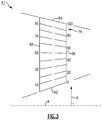
- span positions are schematically illustrated from 0% to 100% in 10% increments to define a plurality of sections 74.
- Each section 74 at a given span position is provided by a conical cut that corresponds to the shape of segments of the core flow path C ( Figure 1 ), as shown by the large dashed lines.
- the 0% span position corresponds to the radially innermost location where the airfoil 61 meets the fillet joining the airfoil section 65 to the platform 62.
- Span position may be relative to the platform 62, such as 0% span at the platform 62 and 100% span at the tip 64, for example.
- the 0% span position corresponds to the radially innermost location where the discrete platform 62 meets the exterior surface of the airfoil section 65 (or the inner platform 72 of vane 70).
- a 100% span position corresponds to a section of the airfoil 61 at the tip 64 (or the outer platform 73 of vane 70).
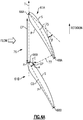
- Figure 4A shows an isolated view of a pair of adjacent airfoils designated as leading airfoil 61A and following airfoil 61B at a first location, such as at a first span position or a location in the turbine section 28.
- the airfoils 61A, 61B of Figure 4A may correspond to high lift airfoils, for example, which are discussed in more detail below.
- each airfoil 61A/61B is sectioned at a radial position between the root section 67 and the tip 64 ( Figures 2 and 3 ).
- the chord dimension (CD) may vary along the span of the airfoil 61A/61B.
- Each airfoil 61A/61B can have an asymmetrical cross-sectional profile characterized by a mean camber line 75.
- the mean camber line 75 extends between leading and trailing edges 66A/66B, 68A/68B to bisect a thickness of the airfoil 61 in the circumferential or thickness direction T.
- Each airfoil 61A/61B defines a camber angle ( ⁇ ) defined by a tangential projection of the mean camber line 75 at the leading and trailing edges 66A/66B, 68A/68B.
- the camber angle ( ⁇ ) can differ at various span positions. For example, the camber angle ( ⁇ ) can decrease as span position increases. In some examples, the camber angle ( ⁇ ) is less than about 45 degrees, or more narrowly less than about 15 degrees, between the 70% span position and the 100% span position, which may be utilized with high lift airfoil geometries, for example.
- the term "about” means ⁇ 3% of the stated value unless otherwise disclosed.
- the leading edges 66A, 66B or trailing edges 68A, 68B of the adjacent airfoils 61A, 61B are separated by a gap or circumferential pitch (CP) in the circumferential or thickness direction T to define an airfoil passage 76.
- Facing pressure and suction sides P, S of adjacent airfoils 61A, 61B define a throat 77.
- the throat 77 is defined as a minimum distance between the facing pressure and suction sides P, S of adjacent airfoils 61A, 61B at a respective span position (see Figure 3 ).
- the throat 77 can include a component in the axial or chordwise direction C in addition to a component in the circumferential or thickness direction T.
- the minimum distance corresponds to a gauge point GP along surfaces of respective facing pressure and suction sides P, S of adjacent airfoils 61A, 61B.
- a location of the gauge point GP can vary depending on a geometry of the corresponding airfoils 61.
- the gauge point GP is defined with respect to the suction side S.
- Figure 4B shows an isolated view of a pair of adjacent airfoils designated as leading airfoil 61A' and following airfoil 61B' at a second location, such as second span position, or at a location in the compressor section 24, for example.
- the airfoil 61 is a "high lift" airfoil.
- the term “high lift airfoil” means an airfoil design that has an airfoil shape that allows for reduced airfoil count due to its ability to extract more work than a conventional airfoil.
- High lift airfoils provide an improvement in efficiency and weight reduction. In using a high lift design, the airfoil stagnation point is shifted from a leading edge nose, where it is located on a conventional airfoil, to the pressure side towards the tip of the airfoil.
- suction side gauge line in which the gas Mach number is at the greatest, on a high lift airfoil can occur much closer to the leading edge nose than a conventional airfoil.
- An exemplary high lift airfoil is disclosed in U.S. Patent Application Serial No. 14/767,768 , entitled “Gas Turbine Engine High Lift Airfoil Cooling in Stagnation Zone,” filed on August 13, 2015 (now published as U.S. Publication No. 2016/0010463 ).
- a cross section of the airfoil 61 at a span position adjacent to the tip 64 is substantially thin and relatively long, and can have a relatively large amount of twist about a radial axis of the airfoil 61.
- a maximum thickness of the airfoil 61 at span positions between 70% span and 100% span can be less than 25% of a maximum thickness of the airfoil 61 at 0% span, or more narrowly less than 10% of the maximum thickness of the airfoil 61 at 0% span.
- the chord dimension (CD) of the airfoil 61 at span positions between 70% span and 100% span is greater than the chord dimension (CD) at 0% span, such as 125% or greater than the chord dimension (CD) at 0% span.
- Sections of example high lift airfoils are illustrated by airfoils 161, 261, 361, 461 ( Figures 5B-C and 6-8 ).
- a localized region of the airfoil 61 between the leading edge 66 and the gauge point GP, including the suction side S of high lift airfoils, can be susceptible to distress due to exposure of relatively high pressures and/or temperatures along the core flow path C ( Figure 1 ), including oxidation, erosion, burnthrough and thermal-mechanical fatigue.
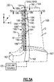
- FIGs 5A and 5B illustrate an exemplary cooling arrangement 180 for an airfoil 161, such as the airfoil 61 of Figure 2 .
- an airfoil 161 such as the airfoil 61 of Figure 2 .
- the exemplary cooling arrangements discussed in the disclosure primarily refer to a compressor or turbine blade, the teachings herein can also be utilized for another portion of the engine 20 such as vane 70 of Figure 2 , for example.
- At least one radial cooling passage 182 (only one shown for illustrative purposes) is provided between pressure and suction sides P, S in the thickness direction T.
- Each radial cooling passage 182 extends from a root section 167 through a platform 162 and toward a tip 164 to communicate coolant to various portions of the airfoil 161.
- Each radial cooling passage 182 is configured to receive coolant from a coolant source CS (shown schematically).
- Exemplary coolant sources CS can include bleed air from an upstream stage of the compressor section 24, bypass air from the bypass flow path B ( Figure 1 ), or a secondary cooling system aboard the aircraft, for example.
- the cooling arrangement 180 includes one or more feeding cavities 184 and impingement cavities 186 extending in the radial direction R (only one feeding cavity 184 and one impingement cavity 186 shown in Figure 5A for illustrative purposes).
- One of the radial passages 182 or another source can communicate coolant to each of the feeding cavities 184 for delivery to the impingement cavities 186.
- the cavities 184, 186 can be formed in various locations of the airfoil 161.
- the impingement cavity 186 is bounded by an external wall 188 of the airfoil 161.
- the external wall 188 defines pressure and suction sides P, S between leading and trailing edges 166, 168 of the airfoil section 165.
- the airfoil section 165 can include multiple feeding cavities 184 and/or impingement cavities 186 to provide cooling to various portions of the airfoil section 165.
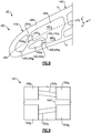
- a pair of impingement cavities 186 can be located at the leading edge 166, as shown in Figure 5B .
- Impingement cavities 186 can be located at the trailing edge 168 or between the leading and trailing edges 166, 168, also shown in Figure 5B .
- the airfoil 161 may include one or more film cooling holes or passages 190 in fluid communication with the feeding cavities 184 and/or impingement cavities 186 to provide film cooling to various surfaces of the airfoil 161.
- the film cooling passages 190 may extend from a surface of the impingement cavity 186, for example.
- the film cooling passages 190 are located within the external wall 188 at the leading edge 166, the trailing edge 168, or another location of the airfoil 161.
- the airfoil 161 can include a thermal barrier coating (TBC) or coating system 192 (shown in dashed lines in Figure 5B ) on an exterior surface of the airfoil section 165 to reduce heat transfer between the gas path and the airfoil section 165.
- TBC thermal barrier coating
- the thermal barrier coating 192 can include, but is not limited to, a ceramic material such as yttria-stabilized zirconia (YSZ).
- YSZ yttria-stabilized zirconia
- the thermal barrier coating 192 can further include a bond layer to facilitate adherence to the substrate.
- One or more crossover passages 194 are located within internal wall 189 of the airfoil section 165, and can be arranged to provide directional or impingement cooling to relatively high heat load regions of the airfoil 161.
- the internal wall 189 includes one or more ribs 193 defined in a thickness of the airfoil that space apart or otherwise separate a respective feeding cavity 184 and impingement cavity 186 or multiples of either.
- Each rib 193 can define a reference plane RF extending in the spanwise or radial direction R along an adjacent surface of the respective impingement cavity 186.
- the reference plane RF can be transverse or perpendicular to mean camber line 175.
- the reference plane RF can be generally planar or can include a curvilinear component, for example.
- the reference plane RF can also include an axial twist between platform 162 and the tip 164.
- each crossover passage 194 extends between an inlet port 195 and an outlet port 196 to connect a respective feeding cavity 184 and impingement cavity 186.
- each outlet port 196 of at least one, or more than one, of the crossover passages 194 is defined at a span position that is between an 70% span position and the 100% span position (see, e.g., crossover passages 194A, 194B of Figure 5A ), and can be arranged utilizing any of the techniques disclosed herein.
- each of the impingement cavities 186A, 186B can be provided with a respective set of crossover passages 194A, 194B each including a plurality of crossover passages 194 at different span positions of the airfoil 161.
- Each of the crossover passages 194 defines a passage axis PA that intersects a surface of the impingement cavity 186 and the feeding cavity 184.
- the passage axis PA can be substantially linear or can include curvilinear portions between the inlet port 195 and outlet port 196, and can intersect the external wall 188 at locations along a leading edge region 179 that defines the leading edge 166 of the airfoil 161.
- leading edge region includes a region of the airfoil section 165 from the leading edge 166 and within 20% of a distance along the external wall 188 between the leading and trailing edges 166, 168, unless otherwise disclosed.
- the crossover passages 194 are arranged such that coolant provided to the feeding cavity 184 is thereafter communicated to the impingement cavity 186.
- the coolant is communicated to the impingement cavity 186 to selectively provide impingement cooling to one or more portions of the external wall 188 of the airfoil 161.
- One or more of the crossover passages 194 can be arranged such that the respective outlet port 196 is spaced apart from the external wall 188 (e.g., crossover passage 194B).
- the crossover passages 194 are shown in Figure 5A as having a uniform distribution in the radial direction R.
- the airfoil 161 includes a non-uniform distribution of at least some of the crossover passages 194 in the radial direction R.
- the airfoil 161 can include fewer or more crossover passages 194.
- Each passage axis PA defines a first or radial angle ( ⁇ ) ( Figure 5A ) relative to the reference plane RF.
- the passage axis PA is substantially perpendicular to the reference plane RF, and the radial angle ( ⁇ ) is approximately equal to 90 degrees such that the crossover passage 194 is substantially parallel with the engine axis A.
- the passage axis PA is transverse to the reference plane RF, and radial angle ( ⁇ ) is not equal to 90 degrees such that the crossover passage 194 is transverse to the engine axis A and slopes towards one of the platform 162 or the tip 164.
- the passage axis PA can define a second or passage angle ( ⁇ ) ( Figure 5C ) with respect to the reference plane RF such that the passage axis PA has a component that extends in the chordwise direction C and such that the crossover passage 194 ejects coolant onto surfaces of the impingement cavity 186 along the passage axis PA to cool a desired portion of the airfoil 161, such as portions of the external wall 188.
- the passage axis PA can include curvilinear portions between the inlet port 195 and outlet port 196, for example, but the passage angle ( ⁇ ) is defined by a linear projection of the passage axis PA from the intersection of the passage axis PA and the reference plane RF at the outlet port 196.
- the crossover passages 194 feeding a common one of the impingement cavities 186 can have the same passage angle ( ⁇ ), or at least some or each of the passage angles ( ⁇ ) can differ to provide different cooling augmentation to different portions of the external wall 188 bounding the respective impingement cavity 186.
- the crossover passage 194 can be defined along various locations of the internal wall 189 or rib 193, and outlet port 196 can be defined along various locations relative to the reference plane RF, including toward the suction side S or the pressure side P.
- the airfoil 161 includes first and second (or a pair of) impingement cavities 186A, 186B that are bounded by external wall 188 at the leading edge region 179, with no other impingement cavities being between the leading edge 166 and the cavities 186A, 186B.
- the cavities 186A, 186B are separate and distinct cavities that provide dedicated impingement cooling to different portions of the airfoil 161 along the leading edge region 179, such as adjacent the respective suction and pressure sides S, P.
- Feeding the impingement cavities 186A, 186B separately with cooling airflow can reduce a likelihood of the impingement cavity 186A adjacent the suction side S being supplied with more cooling airflow than necessary and a likelihood of the impingement cavity 186B adjacent the pressure side P being supplied with insufficient cooling airflow due to starvation, for example.
- the impingement cavities 186A, 186B can provide relatively greater wetted surface area as compared to a single impingement cavity of the same volume, and can improve uniformity of heat transfer between the cooling airflow and portions of the airfoil 161 along the leading edge region 179.
- Each impingement cavity 186 can extend substantially along a span of the airfoil section 165.
- one or more impingement cavities 186' can extend from the tip 164 toward the root section 167
- one or more impingement cavities 186" can extend from the platform 162 or root section 167 toward the tip 164, including any of the impingement cavities disclosed herein (one set of cavities 186' and 186" are shown in dashed line in Figure 5A for illustrative purposes).
- First and second feeding cavities 184A, 184B are separated from the impingement cavities 186A, 186B by the ribs 193A, 193B of the internal wall 189.
- a pair of crossover passages 194A, 194B within ribs 193A, 193B of the internal wall 189 connect the feeding cavities 184A, 184B with the respective impingement cavities 186A, 186B to supply cooling airflow.
- the feeding cavities 184A, 184B are separate and distinct cavities that each receive coolant from the coolant source CS ( Figure 5A ).
- the impingement cavities 186A, 186B are not directly connected to the radial cooling passage 182 ( Figure 5A ) or the coolant source CS and instead receive substantially all cooling airflow from the feeding cavities 184A, 184B.
- the crossover passages 194A, 194B can be sized to provide an adequate backflow margin to reduce a likelihood of ingestion of core air in core flow path C ( Figure 1 ) into impingement cavities 186A, 186B through cooling passages 190 or airflow from the impingement cavities 186A, 186B and into the feeding cavities 184A, 184B.
- the passage angles ( ⁇ A , ⁇ B ) can be the same or can differ to eject cooling airflow on discrete portions of the external wall 188.
- the passage angles ( ⁇ A , ⁇ B ) are transverse to respective reference planes RF A , RF B and are angled toward the suction and pressure sides S, P.
- Passage angle ( ⁇ A ) of crossover passage 194A can be defined such that the passage axis PA A intersects a surface of impingement cavity 186A adjacent to the suction side S.
- Passage angle ( ⁇ B ) of crossover passage 194B can be defined such that the passage axis PA B intersects a surface of impingement cavity 186B adjacent to the pressure side P.
- passage angle ( ⁇ A ) and/or passage angle ( ⁇ B ) is substantially perpendicular to the respective reference planes RF A , RF B or angled inwardly toward the mean camber line 175.
- the passage angle ( ⁇ ) of at least some of the crossover passages 194 can change in the radial direction R. In some examples, the passage angle ( ⁇ ) of at least some or each of the crossover passages 194 changes in the radial direction R such that the passage angles ( ⁇ ) are generally progressively larger or smaller. In other examples, the crossover passages 194 are arranged such that the passage angles ( ⁇ ) increase as span position increases for each, or at least some of, the crossover passages 194. In yet other examples, the crossover passages 194 are arranged such that the passage angles ( ⁇ ) decrease as span position increases for each, or at least some of, the crossover passages 194.
- the passage axis PA of at least some of the crossover passages 194 can intersect the external wall 188 at a respective intersection point PI ( Figure 5C ).
- the intersection point P1 may coincide with the respective gauge point GP, or may be defined aft of gauge point GP' ( Figure 5C ). Said differently, the intersection point P1 can be defined at a position between the trailing edge 168 and the gauge point GP, inclusive of the gauge point GP. In some examples, the intersection point PI is within ⁇ 10% of a distance from the gauge point GP with respect to a length between the gauge point GP and one of the leading and trailing edges 166, 168 along an external wall perimeter of the airfoil 161.
- the passage axis PA of at least one, or each, of the crossover passages 194 is arranged at a corresponding passage angle ( ⁇ ) such that the passage axis PA of the respective crossover passage 194 intersects the external wall 188 at a location between respective gauge point GP and an aftmost location of the impingement cavity 186 with respect to the chordwise direction C.
- the impingement cavity 186 is free of any film cooling passages 190 aft of the gauge point GP.
- the impingement cavity 186 includes at least one film cooling passage 190' (shown in dashed lines in Figure 5C ) aft of the gauge point GP and/or intersection point P1.
- impingement cavities 186 and crossover passages 194 utilizing the teachings herein can provide dedicated cooling augmentation to adjacent portions of the external wall 188 without the need for introducing film cooling passages downstream of the gauge point GP and/or intersection point PI which can result in aerodynamic losses.
- FIG. 6 illustrates a cooling arrangement 280 for an airfoil 261 according to another example.
- Airfoil section 265 includes a pair of impingement cavities 286A, 286B defined in a leading edge region 279 that are supplied with cooling airflow from a pair of feeding cavities 284A, 284B.
- the airfoil 261 along the leading edge region 279 is substantially symmetrical about mean camber line 275 such that the impingement cavities 286A, 286B have substantially the same geometry and volume and such that the feeding cavities 284A, 284B have substantially the same geometry and volume.
- a length of rib 291 that separates cavities 284A, 286A from cavities 284B, 286B follows the mean camber line 275.
- Crossover passages 294A, 294B that connect the impingement cavities 286A, 286B and the respective feeding cavities 284A, 284B are spaced apart from the mean camber line 275.
- FIG. 7 illustrates a cooling arrangement 380 for an airfoil 361 according to yet another example.
- Airfoil section 365 includes a pair of impingement cavities 386A, 386B defined in a leading edge region 379 that are supplied with cooling airflow from a pair of feeding cavities 384A, 384B.
- the impingement cavities 386A, 386B are arranged such that mean camber line 375 intersects impingement cavity 386B and is spaced apart from impingement cavity 386A.
- a rib 393 in the internal wall 389 separates the impingement cavities 386A, 386B.
- a length of the rib 393 extends along a reference plane RR that is substantially transverse to the mean camber line 375, with the reference plane RR intersecting at least one of the pressure and suction sides P, S (e.g., suction side S) along the leading edge region 379.
- the rib 393 can provide reinforcement within a foreign object debris (FOD) region or impact area of the airfoil section 365.
- the FOD region can be susceptible to an increased risk of impact by FOD relative to other portions of the airfoil 361.
- the reference plane RR intersects the mean camber line 375 to define a third or rib angle ( ⁇ ).
- the rib angle ( ⁇ ) is between 30 and 80 degrees, or more narrowly between 45 and 60 degrees.
- the rib 393 can be defined such that inlet 395B and outlet 396B of crossover passage 394B are forward of inlet 395A and outlet 396A of crossover passage 394A with respect to the chordwise direction C.
- Impingement cavity 386B defines a first volume.
- Impingement cavity 386A defines a second, different volume.
- the second volume of impingement cavity 386A is less than about 75%, or more narrowly less than about 50% or half of the first volume of the impingement cavity 386B.
- the different volumes can improve distribution of cooling airflow to the respective impingement cavities 386A, 386B based on cooling demands adjacent the suction and pressure sides S, P of the airfoil 361.
- FIG 8 illustrates a cooling arrangement 480 for an airfoil 461 according to another example.
- Airfoil section 465 includes a pair of impingement cavities 486A, 486B defined in a leading edge region 479 that are supplied with cooling airflow from a common feeding cavity 484.
- the impingement cavities 486A, 486B are arranged such that mean camber line 475 intersects impingement cavity 486B and the common feeding cavity 484 but is spaced apart from impingement cavity 486A.
- the common feeding cavity 484 can be formed from a stepped core to define different regions 485A, 485B that are joined together at a location adjacent the mean camber line 475 and that feed cooling airflow to respective inlets 495A, 495B, for example.
- region 485A extends a different or lesser distance than region 485B with respect to the chordwise direction C.
- the different regions 485A, 485B provide for different positioning of the impingement cavities 486A, 486B, including within leading edge region 479 that can have a relatively narrow thickness or profile in the thickness direction T.
- Both inlet 495B and outlet 496B of crossover passage 494B are forward of inlet 495A and outlet 496A of crossover passage 494A with respect to the chordwise direction C. In other examples, outlet 496B but not inlet 495B is forward of inlet 495A and outlet 496A.
- Figure 9 illustrates a portion of a core 597 according to an example.
- the core 597 can be formed or made via casting, additive, machining, or any method that can produce the geometric shape.
- the core 597 can be utilized in an additive manufacturing process and then used in a casting process, for example, to form the various portions of the cooling arrangements 180/280/380/480.
- the core 597 includes a first portion 598A corresponding to the first impingement cavity 186A/286A/386A/486A, and a second portion 598B corresponding to the second impingement cavity 186B/286B/386B/486B, for example.
- the first portion 598A defines a first volume
- the second portion 598B defines a second, different volume including any of the volumes discussed herein.
- the core 597 includes a third portion 599A corresponding to the first feeding cavity 184A/284A/384A/484A, and a fourth portion 599B corresponding to the second feeding cavity 184B/284B/384B/484B, for example.
- the third and fourth portions 599A, 599B are portions of a common portion 599' (shown in dashed lines) that corresponds to common feeding cavity 484, for example.
- Crossover connectors 500A, 500B which may correspond to one or more of the crossover passages 194/294/394/494, couple or otherwise connect the first and third portions 598A, 599A and the second and fourth portions 598B, 599B, respectively.
- the crossover connectors 500A, 500B can define respective first and second sets of crossover passages 194A/294A/394A/494A, 194B/294B/394B/494B at different span positions of the airfoil 161/261/361/461.
- the crossover connectors 500A, 500B can be arranged to define a passage angle ( ⁇ ) according to any of the corresponding crossover passages 194/294/394/494 disclosed herein.
- the cooling arrangements 180/280/380/480 disclosed herein can improve cooling augmentation to selected portions of the airfoil or vane, including areas susceptible to distress, and can improve airfoil durability and component life. Airfoil designs including high lift airfoils can receive improved impingement cooling in the leading edge region, for example.
- the cooling arrangements 180/280/380/480 can also improve efficiency of the engine 20 due to reducing cooling supply demands, for example.
Landscapes
- Engineering & Computer Science (AREA)
- Mechanical Engineering (AREA)
- General Engineering & Computer Science (AREA)
- Physics & Mathematics (AREA)
- Thermal Sciences (AREA)
- Turbine Rotor Nozzle Sealing (AREA)
Abstract
Description
- This disclosure relates to cooling for a component of a gas turbine engine, including a component having one or more impingement cooling features.
- Gas turbine engines can include a fan for propulsion air and to cool components. The fan also delivers air into an engine core where it is compressed. The compressed air is then delivered into a combustion section, where it is mixed with fuel and ignited. The combustion gas expands downstream and drives turbine blades. Static vanes are positioned adjacent to the turbine blades to control the flow of the products of combustion. The blades and vanes are subject to extreme heat, and thus cooling schemes are utilized for each.
- An airfoil for a gas turbine engine according to an example of the present disclosure includes an airfoil section that has an internal wall and an external wall. The external wall defines pressure and suction sides that extends in a chordwise direction between a leading edge and a trailing edge, a first impingement cavity and a second impingement cavity bounded by the external wall at a leading edge region that defines the leading edge, a first feeding cavity separated from the first impingement cavity and from the second impingement cavity by the internal wall, and a first crossover passage within the internal wall that connects the first impingement cavity and the first feeding cavity. The first crossover passage defines a first passage axis that intersects a surface of the first impingement cavity. A second crossover passage within the internal wall connects to the second impingement cavity. The second crossover passage defines a second passage axis that intersects a surface of the second impingement cavity.
- In a further embodiment of any of the foregoing embodiments, the second crossover passage connects the second impingement cavity and a second feeding cavity. The second feeding cavity separates from the first impingement cavity and from the second impingement cavity by the internal wall.
- In a further embodiment of any of the foregoing embodiments, the first passage axis intersects the surface of the first impingement cavity adjacent to the pressure side, and the second passage axis intersects the surface of the second impingement cavity adjacent to the suction side.
- In a further embodiment of any of the foregoing embodiments, the first crossover passage extends between a first inlet and a first outlet. The second crossover passage extends between a second inlet and a second outlet, and the first inlet is forward of the second outlet with respect to the chordwise direction.
- In a further embodiment of any of the foregoing embodiments, the second crossover passage connects the second impingement cavity and the first feeding cavity, and the first outlet is forward of the second inlet with respect to the chordwise direction.
- In a further embodiment of any of the foregoing embodiments, the first impingement cavity defines a first volume and the second impingement cavity defines a second volume that is less than the first volume.
- In a further embodiment of any of the foregoing embodiments, the airfoil section extends in a spanwise direction from a 0% span position to a 100% span position, and each of an outlet of the first crossover passage and an outlet of the second crossover passage is defined at a span position that is between an 70% span position and the 100% span position.
- In a further embodiment of any of the foregoing embodiments, the airfoil is a high lift airfoil.
- In a further embodiment of any of the foregoing embodiments, the airfoil is a turbine blade.
- In a further embodiment of any of the foregoing embodiments, the airfoil section defines a mean camber line extending between the leading and trailing edges to bisect a thickness of the airfoil section, and a rib separating the first impingement cavity and the second impingement cavity being transverse to the mean camber line.
- In a further embodiment of any of the foregoing embodiments, the first passage axis intersects the external wall at an intersection point. The intersection point is between the trailing edge and a gauge point defined by the airfoil.
- A core for an airfoil according to an example of the present disclosure includes a first portion that corresponds to a first impingement cavity of a leading edge region of an airfoil, a second portion that corresponds to a second impingement cavity of the leading edge region of the airfoil, a third portion that corresponds to a first feeding cavity of the airfoil, and a fourth portion that corresponds to a second feeding cavity of the airfoil. A first set of connectors couple the first portion and the third portion. The first set of connectors correspond to a first set of crossover passages of the airfoil. A second set of connectors couple the second portion and the fourth portion. The second set of connectors correspond to a second set of crossover passages of the airfoil.
- In a further embodiment of any of the foregoing embodiments, the first portion defines a first volume and the second portion defines a second volume that is less than the first volume.
- In a further embodiment of any of the foregoing embodiments, the airfoil is a turbine airfoil.
- A gas turbine engine according to an example of the present disclosure includes an array of airfoils circumferentially distributed about an engine axis. Each airfoil of the array of airfoils has an airfoil section that has an internal wall and an external wall. The external wall defines pressure and suction sides that extends in a chordwise direction between a leading edge and a trailing edge. The airfoil section has a first impingement cavity and a second impingement cavity bounded by the external wall at a leading edge region that defines the leading edge. A first feeding cavity and a second feeding cavity are separated from the first impingement cavity and from the second impingement cavity by the internal wall. A first set of crossover passages within the internal wall connects the first impingement cavity and the first feeding cavity. Each passage of the first set of crossover passages defines a first passage axis that intersects a surface of the first impingement cavity. A second set of crossover passages within the internal wall connects the second impingement cavity and the second feeding cavity. Each passage of the second set of crossover passages defines a second passage axis that intersects a surface of the second impingement cavity.
- A further embodiment of any of the foregoing embodiments includes a compressor section and a turbine section. The array of airfoils are located in at least one of the compressor section and the turbine section.
- In a further embodiment of any of the foregoing embodiments, the array of airfoils are rotatable blades.
- In a further embodiment of any of the foregoing embodiments, each passage of the first set of crossover passages extends between a first inlet and a first outlet, each passage of the second set of crossover passages extends between a second inlet and a second outlet, and both the first inlet and the first outlet are forward of the second outlet with respect to the chordwise direction.
- In a further embodiment of any of the foregoing embodiments, the first impingement cavity defines a first volume and the second impingement cavity defines a second volume that is less than the first volume.
- In a further embodiment of any of the foregoing embodiments, facing pressure and suction sides of adjacent airfoils define a throat that corresponds to a gauge point, the throat defined as a minimum distance between the facing pressure and suction sides at a respective span position. The first passage axis of at least some passages of the first set of crossover passages intersects the external wall at an intersection point. The intersection point is within 10% of a distance from the gauge point with respect to a length between the gauge point and one of the leading edge and the trailing edge.
- Although the different examples have the specific components shown in the illustrations, embodiments of this disclosure are not limited to those particular combinations. It is possible to use some of the components or features from one of the examples in combination with features or components from another one of the examples.
- The various features and advantages of this invention will become apparent to those skilled in the art from the following detailed description of an embodiment. The drawings that accompany the detailed description can be briefly described as follows.
-
-
Figure 1 schematically shows a gas turbine engine. -
Figure 2 schematically shows an airfoil arrangement for a section of a gas turbine engine. -
Figure 3 is a schematic view of airfoil span positions. -
Figure 4A illustrates a cross sectional view of adjacent airfoils according to an example. -
Figure 4B illustrates a cross sectional view of adjacent airfoils according to another example. -
Figure 5A illustrates a side view of a cooling arrangement with an airfoil shown in phantom. -
Figure 5B illustrates a cross sectional view of the cooling arrangement ofFigure 5A alongline 5B-5B. -
Figure 5C illustrates selected portions of the cooling arrangement ofFigure 5B . -
Figure 6 illustrates an exemplary cooling arrangement according to another example. -
Figure 7 illustrates another exemplary cooling arrangement. -
Figure 8 illustrates yet another exemplary cooling arrangement. -
Figure 9 illustrates a core for a cooling arrangement. - Like reference numbers and designations in the various drawings indicate like elements.
-
Figure 1 schematically illustrates agas turbine engine 20. Thegas turbine engine 20 is disclosed herein as a two-spool turbofan that generally incorporates afan section 22, acompressor section 24, a combustor section 26 and aturbine section 28. Alternative engines might include an augmentor section (not shown) among other systems or features. Thefan section 22 drives air along a bypass flow path B in a bypass duct defined within anacelle 15, while thecompressor section 24 drives air along a core flow path C for compression and communication into the combustor section 26 then expansion through theturbine section 28. Although depicted as a two-spool turbofan gas turbine engine in the disclosed non-limiting embodiment, it should be understood that the concepts described herein are not limited to use with two-spool turbofans as the teachings may be applied to other types of turbine engines including three-spool architectures. - The
exemplary engine 20 generally includes alow speed spool 30 and ahigh speed spool 32 mounted for rotation about an engine central longitudinal axis A relative to an enginestatic structure 36 viaseveral bearing systems 38. It should be understood that various bearingsystems 38 at various locations may alternatively or additionally be provided, and the location of bearingsystems 38 may be varied as appropriate to the application. - The
low speed spool 30 generally includes aninner shaft 40 that interconnects afan 42, a first (or low)pressure compressor 44 and a first (or low)pressure turbine 46. Theinner shaft 40 is connected to thefan 42 through a speed change mechanism, which in exemplarygas turbine engine 20 is illustrated as a gearedarchitecture 48 to drive thefan 42 at a lower speed than thelow speed spool 30. Thehigh speed spool 32 includes anouter shaft 50 that interconnects a second (or high)pressure compressor 52 and a second (or high)pressure turbine 54. Acombustor 56 is arranged inexemplary gas turbine 20 between thehigh pressure compressor 52 and thehigh pressure turbine 54. Amid-turbine frame 57 of the enginestatic structure 36 is arranged generally between thehigh pressure turbine 54 and thelow pressure turbine 46. Themid-turbine frame 57 furthersupports bearing systems 38 in theturbine section 28. Theinner shaft 40 and theouter shaft 50 are concentric and rotate via bearingsystems 38 about the engine central longitudinal axis A which is collinear with their longitudinal axes. - The core airflow is compressed by the
low pressure compressor 44 then thehigh pressure compressor 52, mixed and burned with fuel in thecombustor 56, then expanded over thehigh pressure turbine 54 andlow pressure turbine 46. Themid-turbine frame 57 includesairfoils 59 which are in the core airflow path C. Theturbines low speed spool 30 andhigh speed spool 32 in response to the expansion. It will be appreciated that each of the positions of thefan section 22,compressor section 24, combustor section 26,turbine section 28, and fandrive gear system 48 may be varied. For example,gear system 48 may be located aft of combustor section 26 or even aft ofturbine section 28, andfan section 22 may be positioned forward or aft of the location ofgear system 48. - The
engine 20 in one example is a high-bypass geared aircraft engine. In a further example, theengine 20 bypass ratio is greater than about six (6), with an example embodiment being greater than about ten (10), the gearedarchitecture 48 is an epicyclic gear train, such as a planetary gear system or other gear system, with a gear reduction ratio of greater than about 2.3 and thelow pressure turbine 46 has a pressure ratio that is greater than about five. In one disclosed embodiment, theengine 20 bypass ratio is greater than about ten (10:1), the fan diameter is significantly larger than that of thelow pressure compressor 44, and thelow pressure turbine 46 has a pressure ratio that is greater than about five (5:1).Low pressure turbine 46 pressure ratio is pressure measured prior to inlet oflow pressure turbine 46 as related to the pressure at the outlet of thelow pressure turbine 46 prior to an exhaust nozzle. The gearedarchitecture 48 may be an epicycle gear train, such as a planetary gear system or other gear system, with a gear reduction ratio of greater than about 2.3:1. It should be understood, however, that the above parameters are only exemplary of one embodiment of a geared architecture engine and that the present invention is applicable to other gas turbine engines including direct drive turbofans. - A significant amount of thrust is provided by the bypass flow B due to the high bypass ratio. The
fan section 22 of theengine 20 is designed for a particular flight condition -- typically cruise at about 0.8 Mach and about 35,000 feet (10,668 metres). The flight condition of 0.8 Mach and 35,000 ft (10,668 m), with the engine at its best fuel consumption - also known as "bucket cruise Thrust Specific Fuel Consumption ('TSFC')" - is the industry standard parameter of lbm of fuel being burned divided by lbf of thrust the engine produces at that minimum point. "Low fan pressure ratio" is the pressure ratio across the fan blade alone, without a Fan Exit Guide Vane ("FEGV") system. The low fan pressure ratio as disclosed herein according to one non-limiting embodiment is less than about 1.45. "Low corrected fan tip speed" is the actual fan tip speed in ft/sec divided by an industry standard temperature correction of [(Tram °R) / (518.7 °R)]0.5 (where °R = K x 9/5). The "Low corrected fan tip speed" as disclosed herein according to one non-limiting embodiment is less than about 1150 ft / second (350.5 m/s). -
Figure 2 shows selected portions of asection 53 of a gas turbine engine, such as a portion of thecompressor section 24 or theturbine section 28 of theengine 20 ofFigure 1 . Thesection 53 includes arotor 60 carrying one ormore airfoils 61 for rotation about the central axis A. In this disclosure, like reference numerals designate like elements where appropriate and reference numerals with the addition of one-hundred or multiples thereof designate modified elements that are understood to incorporate the same features and benefits of the corresponding original elements. In this example, eachairfoil 61 includes aplatform 62 and anairfoil section 65 extending in a spanwise or radial direction R from theplatform 62 to atip 64. Theairfoil section 65 generally extends in an axial or chordwise direction C between aleading edge 66 and a trailingedge 68, and in a circumferential or thickness direction T between suction and pressure sides S, P. Aroot section 67 of theairfoil 61 is mounted to therotor 60, for example. It should be understood that theairfoil 61 can alternatively be integrally formed with therotor 60, which is sometimes referred to as an integrally bladed rotor (IBR). Theairfoil 61 is rotatable about the central axis A. - A blade outer air seal (BOAS) 69 is spaced radially outward from the
tip 64 of theairfoil section 65. Avane 70 is positioned along the engine axis A and adjacent to theairfoil 61. Thevane 70 includes anairfoil section 71 extending between aninner platform 72 and anouter platform 73 to define a portion of the core flow path C. Thesection 53 includesmultiple airfoils 61,vanes 70, and blade outer air seals 69 arranged circumferentially about the engine axis A. Although the exemplary cooling arrangements discussed in the disclosure primarily refer to arotatable airfoil 61 or turbine blade, the teachings herein can also be utilized for another portion of theengine 20 including static airfoils such asvane 70 and other portions defining a gas path such asBOAS 69, for example. Also, although the teachings herein primarily refer to the leading edge or leading edge region, other portions of the airfoil can benefit from the teachings herein, including trailing edge regions. - Referring to
Figure 3 , span positions are schematically illustrated from 0% to 100% in 10% increments to define a plurality ofsections 74. Eachsection 74 at a given span position is provided by a conical cut that corresponds to the shape of segments of the core flow path C (Figure 1 ), as shown by the large dashed lines. In the case of anairfoil 61 with an integral platform, the 0% span position corresponds to the radially innermost location where theairfoil 61 meets the fillet joining theairfoil section 65 to theplatform 62. Span position may be relative to theplatform 62, such as 0% span at theplatform tip 64, for example. In the case of anairfoil 61 without an integral platform, the 0% span position corresponds to the radially innermost location where thediscrete platform 62 meets the exterior surface of the airfoil section 65 (or theinner platform 72 of vane 70). A 100% span position corresponds to a section of theairfoil 61 at the tip 64 (or theouter platform 73 of vane 70). -
Figure 4A shows an isolated view of a pair of adjacent airfoils designated as leadingairfoil 61A and followingairfoil 61B at a first location, such as at a first span position or a location in theturbine section 28. Theairfoils Figure 4A may correspond to high lift airfoils, for example, which are discussed in more detail below. As shown, eachairfoil 61A/61B is sectioned at a radial position between theroot section 67 and the tip 64 (Figures 2 and3 ). A chord dimension (CD), which is the length between the leading and trailingedges 66A/66B, 68A/68B of theairfoil 61A/61B, forms an angle, or stagger angle α, relative to the chordwise direction C or to a plane parallel to the engine's central longitudinal axis A (Figures 2 and3 ). The chord dimension (CD) may vary along the span of theairfoil 61A/61B. - Each
airfoil 61A/61B can have an asymmetrical cross-sectional profile characterized by amean camber line 75. Themean camber line 75 extends between leading and trailingedges 66A/66B, 68A/68B to bisect a thickness of theairfoil 61 in the circumferential or thickness direction T. - Each
airfoil 61A/61B defines a camber angle (β) defined by a tangential projection of themean camber line 75 at the leading and trailingedges 66A/66B, 68A/68B. The camber angle (β) can differ at various span positions. For example, the camber angle (β) can decrease as span position increases. In some examples, the camber angle (β) is less than about 45 degrees, or more narrowly less than about 15 degrees, between the 70% span position and the 100% span position, which may be utilized with high lift airfoil geometries, for example. For the purposes of this disclosure, the term "about" means ±3% of the stated value unless otherwise disclosed. - The
leading edges edges adjacent airfoils airfoil passage 76. Facing pressure and suction sides P, S ofadjacent airfoils throat 77. Thethroat 77 is defined as a minimum distance between the facing pressure and suction sides P, S ofadjacent airfoils Figure 3 ). Thethroat 77 can include a component in the axial or chordwise direction C in addition to a component in the circumferential or thickness direction T. The minimum distance corresponds to a gauge point GP along surfaces of respective facing pressure and suction sides P, S ofadjacent airfoils airfoils 61. In the illustrated example ofFigure 4A , the gauge point GP is defined with respect to the suction side S.Figure 4B shows an isolated view of a pair of adjacent airfoils designated as leadingairfoil 61A' and followingairfoil 61B' at a second location, such as second span position, or at a location in thecompressor section 24, for example. - In some examples, the
airfoil 61 is a "high lift" airfoil. For the purposes of this disclosure, the term "high lift airfoil" means an airfoil design that has an airfoil shape that allows for reduced airfoil count due to its ability to extract more work than a conventional airfoil. High lift airfoils provide an improvement in efficiency and weight reduction. In using a high lift design, the airfoil stagnation point is shifted from a leading edge nose, where it is located on a conventional airfoil, to the pressure side towards the tip of the airfoil. In addition, the suction side gauge line, in which the gas Mach number is at the greatest, on a high lift airfoil can occur much closer to the leading edge nose than a conventional airfoil. An exemplary high lift airfoil is disclosed inU.S. Patent Application Serial No. 14/767,768 U.S. Publication No. 2016/0010463 ). - In examples, a cross section of the
airfoil 61 at a span position adjacent to thetip 64 is substantially thin and relatively long, and can have a relatively large amount of twist about a radial axis of theairfoil 61. For example, a maximum thickness of theairfoil 61 at span positions between 70% span and 100% span can be less than 25% of a maximum thickness of theairfoil 61 at 0% span, or more narrowly less than 10% of the maximum thickness of theairfoil 61 at 0% span. In other examples, the chord dimension (CD) of theairfoil 61 at span positions between 70% span and 100% span is greater than the chord dimension (CD) at 0% span, such as 125% or greater than the chord dimension (CD) at 0% span. Sections of example high lift airfoils are illustrated byairfoils Figures 5B-C and6-8 ). A localized region of theairfoil 61 between theleading edge 66 and the gauge point GP, including the suction side S of high lift airfoils, can be susceptible to distress due to exposure of relatively high pressures and/or temperatures along the core flow path C (Figure 1 ), including oxidation, erosion, burnthrough and thermal-mechanical fatigue. -
Figures 5A and5B illustrate anexemplary cooling arrangement 180 for anairfoil 161, such as theairfoil 61 ofFigure 2 . Although the exemplary cooling arrangements discussed in the disclosure primarily refer to a compressor or turbine blade, the teachings herein can also be utilized for another portion of theengine 20 such asvane 70 ofFigure 2 , for example. - At least one radial cooling passage 182 (only one shown for illustrative purposes) is provided between pressure and suction sides P, S in the thickness direction T. Each
radial cooling passage 182 extends from aroot section 167 through aplatform 162 and toward atip 164 to communicate coolant to various portions of theairfoil 161. Eachradial cooling passage 182 is configured to receive coolant from a coolant source CS (shown schematically). Exemplary coolant sources CS can include bleed air from an upstream stage of thecompressor section 24, bypass air from the bypass flow path B (Figure 1 ), or a secondary cooling system aboard the aircraft, for example. - The
cooling arrangement 180 includes one ormore feeding cavities 184 andimpingement cavities 186 extending in the radial direction R (only onefeeding cavity 184 and oneimpingement cavity 186 shown inFigure 5A for illustrative purposes). One of theradial passages 182 or another source can communicate coolant to each of the feedingcavities 184 for delivery to theimpingement cavities 186. - The
cavities airfoil 161. In some examples, theimpingement cavity 186 is bounded by anexternal wall 188 of theairfoil 161. Theexternal wall 188 defines pressure and suction sides P, S between leading and trailingedges airfoil section 165. Theairfoil section 165 can include multiple feedingcavities 184 and/orimpingement cavities 186 to provide cooling to various portions of theairfoil section 165. For example, a pair ofimpingement cavities 186 can be located at theleading edge 166, as shown inFigure 5B .Impingement cavities 186 can be located at the trailingedge 168 or between the leading and trailingedges Figure 5B . - The
airfoil 161 may include one or more film cooling holes orpassages 190 in fluid communication with the feedingcavities 184 and/orimpingement cavities 186 to provide film cooling to various surfaces of theairfoil 161. Thefilm cooling passages 190 may extend from a surface of theimpingement cavity 186, for example. In some examples, thefilm cooling passages 190 are located within theexternal wall 188 at theleading edge 166, the trailingedge 168, or another location of theairfoil 161. - The
airfoil 161 can include a thermal barrier coating (TBC) or coating system 192 (shown in dashed lines inFigure 5B ) on an exterior surface of theairfoil section 165 to reduce heat transfer between the gas path and theairfoil section 165. Thethermal barrier coating 192 can include, but is not limited to, a ceramic material such as yttria-stabilized zirconia (YSZ). Thethermal barrier coating 192 can further include a bond layer to facilitate adherence to the substrate. - One or
more crossover passages 194 are located withininternal wall 189 of theairfoil section 165, and can be arranged to provide directional or impingement cooling to relatively high heat load regions of theairfoil 161. Theinternal wall 189 includes one ormore ribs 193 defined in a thickness of the airfoil that space apart or otherwise separate arespective feeding cavity 184 andimpingement cavity 186 or multiples of either. Eachrib 193 can define a reference plane RF extending in the spanwise or radial direction R along an adjacent surface of therespective impingement cavity 186. The reference plane RF can be transverse or perpendicular to meancamber line 175. The reference plane RF can be generally planar or can include a curvilinear component, for example. The reference plane RF can also include an axial twist betweenplatform 162 and thetip 164. - Referring to
Figure 5C , with continued reference toFigures 5A and5B , eachcrossover passage 194 extends between aninlet port 195 and anoutlet port 196 to connect arespective feeding cavity 184 andimpingement cavity 186. In examples, eachoutlet port 196 of at least one, or more than one, of thecrossover passages 194 is defined at a span position that is between an 70% span position and the 100% span position (see, e.g.,crossover passages Figure 5A ), and can be arranged utilizing any of the techniques disclosed herein. Although only one set ofcrossover passages Figure 5 , it should be appreciated that each of the impingement cavities 186A, 186B can be provided with a respective set ofcrossover passages crossover passages 194 at different span positions of theairfoil 161. - Each of the
crossover passages 194 defines a passage axis PA that intersects a surface of theimpingement cavity 186 and thefeeding cavity 184. The passage axis PA can be substantially linear or can include curvilinear portions between theinlet port 195 andoutlet port 196, and can intersect theexternal wall 188 at locations along aleading edge region 179 that defines theleading edge 166 of theairfoil 161. For the purposes of this disclosure, the term "leading edge region" includes a region of theairfoil section 165 from theleading edge 166 and within 20% of a distance along theexternal wall 188 between the leading and trailingedges - The
crossover passages 194 are arranged such that coolant provided to thefeeding cavity 184 is thereafter communicated to theimpingement cavity 186. The coolant is communicated to theimpingement cavity 186 to selectively provide impingement cooling to one or more portions of theexternal wall 188 of theairfoil 161. One or more of thecrossover passages 194 can be arranged such that therespective outlet port 196 is spaced apart from the external wall 188 (e.g.,crossover passage 194B). Thecrossover passages 194 are shown inFigure 5A as having a uniform distribution in the radial direction R. In other examples, theairfoil 161 includes a non-uniform distribution of at least some of thecrossover passages 194 in the radial direction R. Although a particular quantity ofcrossover passages 194 is shown, theairfoil 161 can include fewer ormore crossover passages 194. - Each passage axis PA defines a first or radial angle (γ) (
Figure 5A ) relative to the reference plane RF. In some examples, the passage axis PA is substantially perpendicular to the reference plane RF, and the radial angle (γ) is approximately equal to 90 degrees such that thecrossover passage 194 is substantially parallel with the engine axis A. In other examples, the passage axis PA is transverse to the reference plane RF, and radial angle (γ) is not equal to 90 degrees such that thecrossover passage 194 is transverse to the engine axis A and slopes towards one of theplatform 162 or thetip 164. - The passage axis PA can define a second or passage angle (θ) (
Figure 5C ) with respect to the reference plane RF such that the passage axis PA has a component that extends in the chordwise direction C and such that thecrossover passage 194 ejects coolant onto surfaces of theimpingement cavity 186 along the passage axis PA to cool a desired portion of theairfoil 161, such as portions of theexternal wall 188. The passage axis PA can include curvilinear portions between theinlet port 195 andoutlet port 196, for example, but the passage angle (θ) is defined by a linear projection of the passage axis PA from the intersection of the passage axis PA and the reference plane RF at theoutlet port 196. - The
crossover passages 194 feeding a common one of theimpingement cavities 186 can have the same passage angle (θ), or at least some or each of the passage angles (θ) can differ to provide different cooling augmentation to different portions of theexternal wall 188 bounding therespective impingement cavity 186. Thecrossover passage 194 can be defined along various locations of theinternal wall 189 orrib 193, andoutlet port 196 can be defined along various locations relative to the reference plane RF, including toward the suction side S or the pressure side P. - The
airfoil 161 includes first and second (or a pair of) impingement cavities 186A, 186B that are bounded byexternal wall 188 at theleading edge region 179, with no other impingement cavities being between theleading edge 166 and thecavities 186A, 186B. Thecavities 186A, 186B are separate and distinct cavities that provide dedicated impingement cooling to different portions of theairfoil 161 along theleading edge region 179, such as adjacent the respective suction and pressure sides S, P. Feeding the impingement cavities 186A, 186B separately with cooling airflow can reduce a likelihood of the impingement cavity 186A adjacent the suction side S being supplied with more cooling airflow than necessary and a likelihood of theimpingement cavity 186B adjacent the pressure side P being supplied with insufficient cooling airflow due to starvation, for example. The impingement cavities 186A, 186B can provide relatively greater wetted surface area as compared to a single impingement cavity of the same volume, and can improve uniformity of heat transfer between the cooling airflow and portions of theairfoil 161 along theleading edge region 179. - Each
impingement cavity 186, includingcavities 186A, 186B, can extend substantially along a span of theairfoil section 165. In other examples, one or more impingement cavities 186' can extend from thetip 164 toward theroot section 167, and one ormore impingement cavities 186" can extend from theplatform 162 orroot section 167 toward thetip 164, including any of the impingement cavities disclosed herein (one set ofcavities 186' and 186" are shown in dashed line inFigure 5A for illustrative purposes). - First and
second feeding cavities 184A, 184B are separated from the impingement cavities 186A, 186B by theribs 193A, 193B of theinternal wall 189. A pair ofcrossover passages ribs 193A, 193B of theinternal wall 189 connect thefeeding cavities 184A, 184B with therespective impingement cavities 186A, 186B to supply cooling airflow. In the illustrated example, thefeeding cavities 184A, 184B are separate and distinct cavities that each receive coolant from the coolant source CS (Figure 5A ). The impingement cavities 186A, 186B are not directly connected to the radial cooling passage 182 (Figure 5A ) or the coolant source CS and instead receive substantially all cooling airflow from thefeeding cavities 184A, 184B. Thecrossover passages Figure 1 ) intoimpingement cavities 186A, 186B throughcooling passages 190 or airflow from the impingement cavities 186A, 186B and into thefeeding cavities 184A, 184B. - The passage angles (θA, θB) can be the same or can differ to eject cooling airflow on discrete portions of the
external wall 188. In the illustrated example ofFigure 5C , the passage angles (θA, θB) are transverse to respective reference planes RFA, RFB and are angled toward the suction and pressure sides S, P. Passage angle (θA) ofcrossover passage 194A can be defined such that the passage axis PAA intersects a surface of impingement cavity 186A adjacent to the suction side S. Passage angle (θB) ofcrossover passage 194B can be defined such that the passage axis PAB intersects a surface ofimpingement cavity 186B adjacent to the pressure side P. In other examples, passage angle (θA) and/or passage angle (θB) is substantially perpendicular to the respective reference planes RFA, RFB or angled inwardly toward themean camber line 175. - The passage angle (θ) of at least some of the
crossover passages 194 can change in the radial direction R. In some examples, the passage angle (θ) of at least some or each of thecrossover passages 194 changes in the radial direction R such that the passage angles (θ) are generally progressively larger or smaller. In other examples, thecrossover passages 194 are arranged such that the passage angles (θ) increase as span position increases for each, or at least some of, thecrossover passages 194. In yet other examples, thecrossover passages 194 are arranged such that the passage angles (θ) decrease as span position increases for each, or at least some of, thecrossover passages 194. - The passage axis PA of at least some of the
crossover passages 194 can intersect theexternal wall 188 at a respective intersection point PI (Figure 5C ). The intersection point P1 may coincide with the respective gauge point GP, or may be defined aft of gauge point GP' (Figure 5C ). Said differently, the intersection point P1 can be defined at a position between the trailingedge 168 and the gauge point GP, inclusive of the gauge point GP. In some examples, the intersection point PI is within ±10% of a distance from the gauge point GP with respect to a length between the gauge point GP and one of the leading and trailingedges airfoil 161. - The passage axis PA of at least one, or each, of the
crossover passages 194 is arranged at a corresponding passage angle (θ) such that the passage axis PA of therespective crossover passage 194 intersects theexternal wall 188 at a location between respective gauge point GP and an aftmost location of theimpingement cavity 186 with respect to the chordwise direction C. In the illustrated example ofFigure 5C , theimpingement cavity 186 is free of anyfilm cooling passages 190 aft of the gauge point GP. In alternative examples, theimpingement cavity 186 includes at least one film cooling passage 190' (shown in dashed lines inFigure 5C ) aft of the gauge point GP and/or intersection point P1. - The arrangement of the
impingement cavities 186 andcrossover passages 194 utilizing the teachings herein can provide dedicated cooling augmentation to adjacent portions of theexternal wall 188 without the need for introducing film cooling passages downstream of the gauge point GP and/or intersection point PI which can result in aerodynamic losses. -
Figure 6 illustrates acooling arrangement 280 for anairfoil 261 according to another example.Airfoil section 265 includes a pair of impingement cavities 286A, 286B defined in aleading edge region 279 that are supplied with cooling airflow from a pair of feedingcavities 284A, 284B. As shown, theairfoil 261 along theleading edge region 279 is substantially symmetrical aboutmean camber line 275 such that the impingement cavities 286A, 286B have substantially the same geometry and volume and such that thefeeding cavities 284A, 284B have substantially the same geometry and volume. A length ofrib 291 that separates cavities 284A, 286A fromcavities mean camber line 275.Crossover passages 294A, 294B that connect the impingement cavities 286A, 286B and therespective feeding cavities 284A, 284B are spaced apart from themean camber line 275. -
Figure 7 illustrates acooling arrangement 380 for anairfoil 361 according to yet another example.Airfoil section 365 includes a pair of impingement cavities 386A, 386B defined in a leading edge region 379 that are supplied with cooling airflow from a pair of feedingcavities 384A, 384B. The impingement cavities 386A, 386B are arranged such thatmean camber line 375 intersectsimpingement cavity 386B and is spaced apart from impingement cavity 386A. - A rib 393 in the
internal wall 389 separates the impingement cavities 386A, 386B. A length of the rib 393 extends along a reference plane RR that is substantially transverse to themean camber line 375, with the reference plane RR intersecting at least one of the pressure and suction sides P, S (e.g., suction side S) along the leading edge region 379. The rib 393 can provide reinforcement within a foreign object debris (FOD) region or impact area of theairfoil section 365. The FOD region can be susceptible to an increased risk of impact by FOD relative to other portions of theairfoil 361. The reference plane RR intersects themean camber line 375 to define a third or rib angle (β). In examples, the rib angle (β) is between 30 and 80 degrees, or more narrowly between 45 and 60 degrees. The rib 393 can be defined such thatinlet 395B andoutlet 396B ofcrossover passage 394B are forward of inlet 395A and outlet 396A of crossover passage 394A with respect to the chordwise direction C. -
Impingement cavity 386B defines a first volume. Impingement cavity 386A defines a second, different volume. In some examples, the second volume of impingement cavity 386A is less than about 75%, or more narrowly less than about 50% or half of the first volume of theimpingement cavity 386B. The different volumes can improve distribution of cooling airflow to therespective impingement cavities 386A, 386B based on cooling demands adjacent the suction and pressure sides S, P of theairfoil 361. -
Figure 8 illustrates acooling arrangement 480 for anairfoil 461 according to another example.Airfoil section 465 includes a pair of impingement cavities 486A, 486B defined in aleading edge region 479 that are supplied with cooling airflow from acommon feeding cavity 484. The impingement cavities 486A, 486B are arranged such thatmean camber line 475 intersects impingement cavity 486B and thecommon feeding cavity 484 but is spaced apart fromimpingement cavity 486A. - The
common feeding cavity 484 can be formed from a stepped core to definedifferent regions 485A, 485B that are joined together at a location adjacent themean camber line 475 and that feed cooling airflow torespective inlets 495A, 495B, for example. In the illustrated example, region 485A extends a different or lesser distance thanregion 485B with respect to the chordwise direction C. Thedifferent regions 485A, 485B provide for different positioning of the impingement cavities 486A, 486B, including within leadingedge region 479 that can have a relatively narrow thickness or profile in the thickness direction T. Bothinlet 495B andoutlet 496B ofcrossover passage 494B are forward of inlet 495A and outlet 496A of crossover passage 494A with respect to the chordwise direction C. In other examples,outlet 496B but notinlet 495B is forward of inlet 495A and outlet 496A. -
Figure 9 illustrates a portion of a core 597 according to an example. Thecore 597 can be formed or made via casting, additive, machining, or any method that can produce the geometric shape. Thecore 597 can be utilized in an additive manufacturing process and then used in a casting process, for example, to form the various portions of the coolingarrangements 180/280/380/480. - The
core 597 includes afirst portion 598A corresponding to the first impingement cavity 186A/286A/386A/486A, and asecond portion 598B corresponding to thesecond impingement cavity 186B/286B/ 386B/486B, for example. In examples, thefirst portion 598A defines a first volume, and thesecond portion 598B defines a second, different volume including any of the volumes discussed herein. - The
core 597 includes athird portion 599A corresponding to the first feeding cavity 184A/284A/384A/484A, and afourth portion 599B corresponding to thesecond feeding cavity 184B/284B/ 384B/484B, for example. In embodiments, the third andfourth portions common feeding cavity 484, for example. -
Crossover connectors crossover passages 194/294/394/494, couple or otherwise connect the first andthird portions fourth portions crossover connectors crossover passages 194A/294A/394A/494A, 194B/294B/ 394B/494B at different span positions of theairfoil 161/261/361/461. Thecrossover connectors corresponding crossover passages 194/294/394/494 disclosed herein. - The cooling
arrangements 180/280/380/480 disclosed herein can improve cooling augmentation to selected portions of the airfoil or vane, including areas susceptible to distress, and can improve airfoil durability and component life. Airfoil designs including high lift airfoils can receive improved impingement cooling in the leading edge region, for example. The coolingarrangements 180/280/380/480 can also improve efficiency of theengine 20 due to reducing cooling supply demands, for example. - Although particular step sequences are shown, described, and claimed, it should be understood that steps may be performed in any order, separated or combined unless otherwise indicated and will still benefit from the present disclosure.
- It should be understood that relative positional terms such as "forward," "aft," "upper," "lower," "above," "below," and the like are with reference to the normal operational attitude of the vehicle and should not be considered otherwise limiting.
- The foregoing description is exemplary rather than defined by the limitations within. Various non-limiting embodiments are disclosed herein, however, one of ordinary skill in the art would recognize that various modifications and variations in light of the above teachings will fall within the scope of the appended claims. It is therefore to be understood that within the scope of the appended claims, the disclosure may be practiced other than as specifically described. For that reason the appended claims should be studied to determine true scope and content.
Claims (15)
- An airfoil (161) for a gas turbine engine (20) comprising:an airfoil section (165) having an internal wall (189) and an external wall (188), the external wall (188) defining pressure and suction sides (P, S) extending in a chordwise direction (C) between a leading edge (166) and a trailing edge (168);a first impingement cavity (186A) and a second impingement cavity (186B) bounded by the external wall (188) at a leading edge region that defines the leading edge (166);a first feeding cavity (184A) separated from the first impingement cavity (186A) and from the second impingement cavity (186B) by the internal wall (189);a first crossover passage (194A) within the internal wall (189) that connects the first impingement cavity (186A) and the first feeding cavity (184A), wherein the first crossover passage (194A) defines a first passage axis (PAA) that intersects a surface of the first impingement cavity (186A); anda second crossover passage (194B) within the internal wall (189) connected to the second impingement cavity (186B), wherein the second crossover passage (194B) defines a second passage axis (PAB) that intersects a surface of the second impingement cavity (186B).
- The airfoil (161) as recited in claim 1, wherein the second crossover passage (194B) connects the second impingement cavity (186B) and a second feeding cavity (184B), the second feeding cavity (184B) separated from the first impingement cavity (186A) and from the second impingement cavity (186B) by the internal wall (189).
- The airfoil (161) as recited in claim 1 or 2, wherein the first passage axis (PAA) intersects the surface of the first impingement cavity (186A) adjacent to the pressure side (P), and the second passage axis (PAB) intersects the surface of the second impingement cavity (186B) adjacent to the suction side (S).
- The airfoil (361) as recited in any preceding claim, wherein the first crossover passage (394B) extends between a first inlet (395B) and a first outlet (396B), the second crossover passage (394A) extends between a second inlet (395A) and a second outlet (396A), and the first inlet (395B) is forward of the second outlet (396A) with respect to the chordwise direction (C).
- The airfoil (361) as recited in claim 4, wherein the second crossover passage (394A) connects the second impingement cavity (386A) and the second feeding cavity (384A), and the first outlet (396B) is forward of the second inlet (395A) with respect to the chordwise direction (C).
- The airfoil (161) as recited in any preceding claim, wherein the airfoil section (165) extends in a spanwise direction from a 0% span position to a 100% span position, and each of an outlet (196) of the first crossover passage (194A) and an outlet (196) of the second crossover passage (194B) is defined at a span position that is between an 70% span position and the 100% span position, wherein the airfoil (161) is optionally a high lift airfoil.
- The airfoil (361) as recited in any preceding claim, wherein the airfoil section (365) defines a mean camber line (375) extending between the leading and trailing edges (366, 68) to bisect a thickness of the airfoil section (365), and a rib (393) separating the first impingement cavity (386A) and the second impingement cavity (386B) being transverse to the mean camber line (375).
- The airfoil (161) as recited in any preceding claim, wherein the first passage axis (PAA) intersects the external wall (188) at an intersection point (P1), the intersection point (P1) being between the trailing edge (168) and a gauge point (GP) defined by the airfoil (161).
- A core (597) for an airfoil (161), comprising:a first portion (598A) corresponding to a first impingement cavity (186A) of a leading edge region of an airfoil (161);a second portion (598B) corresponding to a second impingement cavity (186B) of the leading edge region of the airfoil (161);a third portion (599A) corresponding to a first feeding cavity (184A) of the airfoil (161);a fourth portion (599B) corresponding to a second feeding cavity (184B) of the airfoil (161);a first set of connectors (500A) coupling the first portion (598A) and the third portion (599A), the first set of connectors (500A) corresponding to a first set of crossover passages (194A) of the airfoil (161); anda second set of connectors (500B) coupling the second portion (598B) and the fourth portion (599B), the second set of connectors (500B) corresponding to a second set of crossover passages (194B) of the airfoil (161).
- The airfoil (161) or core (592) for an airfoil (161) as recited in any preceding claim, wherein the airfoil (161) is a turbine airfoil or a turbine blade.
- A gas turbine engine (20), comprising:an array of airfoils (161) circumferentially distributed about an engine axis (A), each airfoil of the array of airfoils (161) including an airfoil section (165) having an internal wall (189) and an external wall (188), the external wall (188) defining pressure and suction sides (P, S) extending in a chordwise direction (C) between a leading edge (166) and a trailing edge (168); andwherein the airfoil section (165) comprises:a first impingement cavity (186A) and a second impingement cavity (186B) bounded by the external wall (188) at a leading edge region that defines the leading edge (166);a first feeding cavity (184A) and a second feeding cavity (184B) separated from the first impingement cavity (186A) and from the second impingement cavity (186B) by the internal wall (189);a first set of crossover passages (194A) within the internal wall (189) that connect the first impingement cavity (186A) and the first feeding cavity (184A), wherein each passage (194A) of the first set of crossover passages (194A) defines a first passage axis (PAA) that intersects a surface of the first impingement cavity (186A); anda second set of crossover passages (194B) within the internal wall (189) that connect the second impingement cavity (186B) and the second feeding cavity (184B), wherein each passage (194B) of the second set of crossover passages (194B) defines a second passage axis (PAB) that intersects a surface of the second impingement cavity (186B).
- The gas turbine engine (20) as recited in claim 11, comprising a compressor section (24) and a turbine section (28), wherein the array of airfoils (161) are located in at least one of the compressor section (24) and the turbine section (28), wherein the array of airfoils (161) are optionally rotatable blades.
- The gas turbine engine (20) as recited in claim 11 or 12, wherein each passage (394B) of the first set of crossover passages (394B) extends between a first inlet (395B) and a first outlet (396B), each passage (394A) of the second set of crossover passages (394A) extends between a second inlet (395A) and a second outlet (396A), and both the first inlet (395B) and the first outlet (396B) are forward of the second outlet (396A) with respect to the chordwise direction (C).
- The gas turbine engine (20) as recited in any of claims 11 to 13, wherein:facing pressure and suction sides (P, S) of adjacent airfoils (61A; 61B) define a throat (77) that corresponds to a gauge point (GP), the throat (77) defined as a minimum distance between the facing pressure and suction sides (P, S) at a respective span position; andwherein the first passage axis (PAA) of at least some passages (194A) of the first set of crossover passages (194A) intersects the external wall (188) at an intersection point (P1), the intersection point (P1) being within 10% of a distance from the gauge point (GP) with respect to a length between the gauge point (GP) and one of the leading edge (166) and the trailing edge (168).
- The airfoil (161), core (597) for an airfoil (161) or gas turbine engine (20) as recited in any preceding claim, wherein the first portion (598A) or the first impingement cavity (186A) defines a first volume and the second portion (598B) or the second impingement cavity (186B) defines a second volume that is less than the first volume.
Applications Claiming Priority (1)
| Application Number | Priority Date | Filing Date | Title |
|---|---|---|---|
| US15/866,557 US10570748B2 (en) | 2018-01-10 | 2018-01-10 | Impingement cooling arrangement for airfoils |
Publications (2)
| Publication Number | Publication Date |
|---|---|
| EP3511523A1 true EP3511523A1 (en) | 2019-07-17 |
| EP3511523B1 EP3511523B1 (en) | 2021-06-30 |
Family
ID=65010608
Family Applications (1)
| Application Number | Title | Priority Date | Filing Date |
|---|---|---|---|
| EP19150752.4A Active EP3511523B1 (en) | 2018-01-10 | 2019-01-08 | Impingement cooling arrangement for airfoils |
Country Status (2)
| Country | Link |
|---|---|
| US (2) | US10570748B2 (en) |
| EP (1) | EP3511523B1 (en) |
Cited By (2)
| Publication number | Priority date | Publication date | Assignee | Title |
|---|---|---|---|---|
| EP3822454A1 (en) * | 2019-11-14 | 2021-05-19 | Raytheon Technologies Corporation | Airfoil with connective rib |
| US11634994B2 (en) | 2021-05-19 | 2023-04-25 | Rolls-Royce Plc | Nozzle guide vane |
Citations (7)
| Publication number | Priority date | Publication date | Assignee | Title |
|---|---|---|---|---|
| US5624231A (en) * | 1993-12-28 | 1997-04-29 | Kabushiki Kaisha Toshiba | Cooled turbine blade for a gas turbine |
| US20050265838A1 (en) * | 2003-03-12 | 2005-12-01 | George Liang | Leading edge diffusion cooling of a turbine airfoil for a gas turbine engine |
| US20060002795A1 (en) * | 2004-07-02 | 2006-01-05 | Siemens Westinghouse Power Corporation | Impingement cooling system for a turbine blade |
| US20080080979A1 (en) * | 2005-02-21 | 2008-04-03 | General Electric Company | Airfoil cooling circuits and method |
| US7520725B1 (en) * | 2006-08-11 | 2009-04-21 | Florida Turbine Technologies, Inc. | Turbine airfoil with near-wall leading edge multi-holes cooling |
| US20130081408A1 (en) * | 2011-09-30 | 2013-04-04 | Steve Mark Molter | Method and apparatus for cooling gas turbine rotor blades |
| US20160010463A1 (en) | 2013-03-04 | 2016-01-14 | United Technologies Corporation | Gas turbine engine high lift airfoil cooling in stagnation zone |
Family Cites Families (20)
| Publication number | Priority date | Publication date | Assignee | Title |
|---|---|---|---|---|
| GB2260166B (en) | 1985-10-18 | 1993-06-30 | Rolls Royce | Cooled aerofoil blade or vane for a gas turbine engine |
| US5246340A (en) | 1991-11-19 | 1993-09-21 | Allied-Signal Inc. | Internally cooled airfoil |
| US5271715A (en) | 1992-12-21 | 1993-12-21 | United Technologies Corporation | Cooled turbine blade |
| US5498133A (en) | 1995-06-06 | 1996-03-12 | General Electric Company | Pressure regulated film cooling |
| US6168381B1 (en) * | 1999-06-29 | 2001-01-02 | General Electric Company | Airfoil isolated leading edge cooling |
| US7581930B2 (en) | 2006-08-16 | 2009-09-01 | United Technologies Corporation | High lift transonic turbine blade |
| US7530789B1 (en) * | 2006-11-16 | 2009-05-12 | Florida Turbine Technologies, Inc. | Turbine blade with a serpentine flow and impingement cooling circuit |
| US7722326B2 (en) | 2007-03-13 | 2010-05-25 | Siemens Energy, Inc. | Intensively cooled trailing edge of thin airfoils for turbine engines |
| US7862299B1 (en) | 2007-03-21 | 2011-01-04 | Florida Turbine Technologies, Inc. | Two piece hollow turbine blade with serpentine cooling circuits |
| GB0800361D0 (en) | 2008-01-10 | 2008-02-20 | Rolls Royce Plc | Blade cooling |
| ES2442873T3 (en) | 2008-03-31 | 2014-02-14 | Alstom Technology Ltd | Aerodynamic gas turbine profile |
| US8210814B2 (en) | 2008-06-18 | 2012-07-03 | General Electric Company | Crossflow turbine airfoil |
| GB0811391D0 (en) | 2008-06-23 | 2008-07-30 | Rolls Royce Plc | A rotor blade |
| US8366395B1 (en) * | 2010-10-21 | 2013-02-05 | Florida Turbine Technologies, Inc. | Turbine blade with cooling |
| US20130156602A1 (en) | 2011-12-16 | 2013-06-20 | United Technologies Corporation | Film cooled turbine component |
| EP2752554A1 (en) | 2013-01-03 | 2014-07-09 | Siemens Aktiengesellschaft | Blade for a turbomachine |
| US9376922B2 (en) | 2013-01-09 | 2016-06-28 | General Electric Company | Interior configuration for turbine rotor blade |
| US8864469B1 (en) | 2014-01-20 | 2014-10-21 | Florida Turbine Technologies, Inc. | Turbine rotor blade with super cooling |
| US10012090B2 (en) | 2014-07-25 | 2018-07-03 | United Technologies Corporation | Airfoil cooling apparatus |
| US10406596B2 (en) * | 2015-05-01 | 2019-09-10 | United Technologies Corporation | Core arrangement for turbine engine component |
-
2018
- 2018-01-10 US US15/866,557 patent/US10570748B2/en active Active
-
2019
- 2019-01-08 EP EP19150752.4A patent/EP3511523B1/en active Active
-
2020
- 2020-01-06 US US16/734,464 patent/US11255197B2/en active Active
Patent Citations (7)
| Publication number | Priority date | Publication date | Assignee | Title |
|---|---|---|---|---|
| US5624231A (en) * | 1993-12-28 | 1997-04-29 | Kabushiki Kaisha Toshiba | Cooled turbine blade for a gas turbine |
| US20050265838A1 (en) * | 2003-03-12 | 2005-12-01 | George Liang | Leading edge diffusion cooling of a turbine airfoil for a gas turbine engine |
| US20060002795A1 (en) * | 2004-07-02 | 2006-01-05 | Siemens Westinghouse Power Corporation | Impingement cooling system for a turbine blade |
| US20080080979A1 (en) * | 2005-02-21 | 2008-04-03 | General Electric Company | Airfoil cooling circuits and method |
| US7520725B1 (en) * | 2006-08-11 | 2009-04-21 | Florida Turbine Technologies, Inc. | Turbine airfoil with near-wall leading edge multi-holes cooling |
| US20130081408A1 (en) * | 2011-09-30 | 2013-04-04 | Steve Mark Molter | Method and apparatus for cooling gas turbine rotor blades |
| US20160010463A1 (en) | 2013-03-04 | 2016-01-14 | United Technologies Corporation | Gas turbine engine high lift airfoil cooling in stagnation zone |
Cited By (3)
| Publication number | Priority date | Publication date | Assignee | Title |
|---|---|---|---|---|
| EP3822454A1 (en) * | 2019-11-14 | 2021-05-19 | Raytheon Technologies Corporation | Airfoil with connective rib |
| US11952911B2 (en) | 2019-11-14 | 2024-04-09 | Rtx Corporation | Airfoil with connecting rib |
| US11634994B2 (en) | 2021-05-19 | 2023-04-25 | Rolls-Royce Plc | Nozzle guide vane |
Also Published As
| Publication number | Publication date |
|---|---|
| US10570748B2 (en) | 2020-02-25 |
| EP3511523B1 (en) | 2021-06-30 |
| US20200149409A1 (en) | 2020-05-14 |
| US11255197B2 (en) | 2022-02-22 |
| US20190211689A1 (en) | 2019-07-11 |
Similar Documents
| Publication | Publication Date | Title |
|---|---|---|
| US11148191B2 (en) | Core arrangement for turbine engine component | |
| EP3444436B1 (en) | Directional cooling arrangement for turbine airfoils | |
| EP2993302B1 (en) | Airfoil with staggered crossover passages and corresponding casting core | |
| US10253635B2 (en) | Blade tip cooling arrangement | |
| US11781439B2 (en) | Seal arrangement for turbine engine component | |
| US10677069B2 (en) | Component core with shaped edges | |
| EP3032035A2 (en) | Staggered crossovers for airfoils | |
| EP3342982B1 (en) | Inclined crossover passages for internal airfoil cavities | |
| EP3078807B2 (en) | Cooling passages for a gas turbine engine component | |
| EP3511523B1 (en) | Impingement cooling arrangement for airfoils | |
| EP3587734A1 (en) | Cooling arrangement with crenellation features for gas turbine engine component | |
| EP3954867B1 (en) | Cooling arrangement including overlapping diffusers |
Legal Events
| Date | Code | Title | Description |
|---|---|---|---|
| PUAI | Public reference made under article 153(3) epc to a published international application that has entered the european phase |
Free format text: ORIGINAL CODE: 0009012 |
|
| STAA | Information on the status of an ep patent application or granted ep patent |
Free format text: STATUS: THE APPLICATION HAS BEEN PUBLISHED |
|
| AK | Designated contracting states |
Kind code of ref document: A1 Designated state(s): AL AT BE BG CH CY CZ DE DK EE ES FI FR GB GR HR HU IE IS IT LI LT LU LV MC MK MT NL NO PL PT RO RS SE SI SK SM TR |
|
| AX | Request for extension of the european patent |
Extension state: BA ME |
|
| STAA | Information on the status of an ep patent application or granted ep patent |
Free format text: STATUS: REQUEST FOR EXAMINATION WAS MADE |
|
| 17P | Request for examination filed |
Effective date: 20200117 |
|
| RBV | Designated contracting states (corrected) |
Designated state(s): AL AT BE BG CH CY CZ DE DK EE ES FI FR GB GR HR HU IE IS IT LI LT LU LV MC MK MT NL NO PL PT RO RS SE SI SK SM TR |
|
| STAA | Information on the status of an ep patent application or granted ep patent |
Free format text: STATUS: EXAMINATION IS IN PROGRESS |
|
| 17Q | First examination report despatched |
Effective date: 20200821 |
|
| GRAP | Despatch of communication of intention to grant a patent |
Free format text: ORIGINAL CODE: EPIDOSNIGR1 |
|
| STAA | Information on the status of an ep patent application or granted ep patent |
Free format text: STATUS: GRANT OF PATENT IS INTENDED |
|
| RAP1 | Party data changed (applicant data changed or rights of an application transferred) |
Owner name: RAYTHEON TECHNOLOGIES CORPORATION |
|
| INTG | Intention to grant announced |
Effective date: 20210310 |
|
| GRAS | Grant fee paid |
Free format text: ORIGINAL CODE: EPIDOSNIGR3 |
|
| GRAA | (expected) grant |
Free format text: ORIGINAL CODE: 0009210 |
|
| STAA | Information on the status of an ep patent application or granted ep patent |
Free format text: STATUS: THE PATENT HAS BEEN GRANTED |
|
| AK | Designated contracting states |
Kind code of ref document: B1 Designated state(s): AL AT BE BG CH CY CZ DE DK EE ES FI FR GB GR HR HU IE IS IT LI LT LU LV MC MK MT NL NO PL PT RO RS SE SI SK SM TR |
|
| REG | Reference to a national code |
Ref country code: CH Ref legal event code: EP |
|
| REG | Reference to a national code |
Ref country code: AT Ref legal event code: REF Ref document number: 1406516 Country of ref document: AT Kind code of ref document: T Effective date: 20210715 |
|
| REG | Reference to a national code |
Ref country code: DE Ref legal event code: R096 Ref document number: 602019005614 Country of ref document: DE |
|
| REG | Reference to a national code |
Ref country code: IE Ref legal event code: FG4D |
|
| REG | Reference to a national code |
Ref country code: LT Ref legal event code: MG9D |
|
| PG25 | Lapsed in a contracting state [announced via postgrant information from national office to epo] |
Ref country code: BG Free format text: LAPSE BECAUSE OF FAILURE TO SUBMIT A TRANSLATION OF THE DESCRIPTION OR TO PAY THE FEE WITHIN THE PRESCRIBED TIME-LIMIT Effective date: 20210930 Ref country code: FI Free format text: LAPSE BECAUSE OF FAILURE TO SUBMIT A TRANSLATION OF THE DESCRIPTION OR TO PAY THE FEE WITHIN THE PRESCRIBED TIME-LIMIT Effective date: 20210630 Ref country code: HR Free format text: LAPSE BECAUSE OF FAILURE TO SUBMIT A TRANSLATION OF THE DESCRIPTION OR TO PAY THE FEE WITHIN THE PRESCRIBED TIME-LIMIT Effective date: 20210630 |
|
| REG | Reference to a national code |
Ref country code: NL Ref legal event code: MP Effective date: 20210630 |
|
| REG | Reference to a national code |
Ref country code: AT Ref legal event code: MK05 Ref document number: 1406516 Country of ref document: AT Kind code of ref document: T Effective date: 20210630 |
|
| PG25 | Lapsed in a contracting state [announced via postgrant information from national office to epo] |
Ref country code: GR Free format text: LAPSE BECAUSE OF FAILURE TO SUBMIT A TRANSLATION OF THE DESCRIPTION OR TO PAY THE FEE WITHIN THE PRESCRIBED TIME-LIMIT Effective date: 20211001 Ref country code: NO Free format text: LAPSE BECAUSE OF FAILURE TO SUBMIT A TRANSLATION OF THE DESCRIPTION OR TO PAY THE FEE WITHIN THE PRESCRIBED TIME-LIMIT Effective date: 20210930 Ref country code: LV Free format text: LAPSE BECAUSE OF FAILURE TO SUBMIT A TRANSLATION OF THE DESCRIPTION OR TO PAY THE FEE WITHIN THE PRESCRIBED TIME-LIMIT Effective date: 20210630 Ref country code: RS Free format text: LAPSE BECAUSE OF FAILURE TO SUBMIT A TRANSLATION OF THE DESCRIPTION OR TO PAY THE FEE WITHIN THE PRESCRIBED TIME-LIMIT Effective date: 20210630 Ref country code: SE Free format text: LAPSE BECAUSE OF FAILURE TO SUBMIT A TRANSLATION OF THE DESCRIPTION OR TO PAY THE FEE WITHIN THE PRESCRIBED TIME-LIMIT Effective date: 20210630 |
|
| PG25 | Lapsed in a contracting state [announced via postgrant information from national office to epo] |
Ref country code: SK Free format text: LAPSE BECAUSE OF FAILURE TO SUBMIT A TRANSLATION OF THE DESCRIPTION OR TO PAY THE FEE WITHIN THE PRESCRIBED TIME-LIMIT Effective date: 20210630 Ref country code: EE Free format text: LAPSE BECAUSE OF FAILURE TO SUBMIT A TRANSLATION OF THE DESCRIPTION OR TO PAY THE FEE WITHIN THE PRESCRIBED TIME-LIMIT Effective date: 20210630 Ref country code: ES Free format text: LAPSE BECAUSE OF FAILURE TO SUBMIT A TRANSLATION OF THE DESCRIPTION OR TO PAY THE FEE WITHIN THE PRESCRIBED TIME-LIMIT Effective date: 20210630 Ref country code: NL Free format text: LAPSE BECAUSE OF FAILURE TO SUBMIT A TRANSLATION OF THE DESCRIPTION OR TO PAY THE FEE WITHIN THE PRESCRIBED TIME-LIMIT Effective date: 20210630 Ref country code: PT Free format text: LAPSE BECAUSE OF FAILURE TO SUBMIT A TRANSLATION OF THE DESCRIPTION OR TO PAY THE FEE WITHIN THE PRESCRIBED TIME-LIMIT Effective date: 20211102 Ref country code: RO Free format text: LAPSE BECAUSE OF FAILURE TO SUBMIT A TRANSLATION OF THE DESCRIPTION OR TO PAY THE FEE WITHIN THE PRESCRIBED TIME-LIMIT Effective date: 20210630 Ref country code: SM Free format text: LAPSE BECAUSE OF FAILURE TO SUBMIT A TRANSLATION OF THE DESCRIPTION OR TO PAY THE FEE WITHIN THE PRESCRIBED TIME-LIMIT Effective date: 20210630 Ref country code: AT Free format text: LAPSE BECAUSE OF FAILURE TO SUBMIT A TRANSLATION OF THE DESCRIPTION OR TO PAY THE FEE WITHIN THE PRESCRIBED TIME-LIMIT Effective date: 20210630 Ref country code: CZ Free format text: LAPSE BECAUSE OF FAILURE TO SUBMIT A TRANSLATION OF THE DESCRIPTION OR TO PAY THE FEE WITHIN THE PRESCRIBED TIME-LIMIT Effective date: 20210630 |
|
| PG25 | Lapsed in a contracting state [announced via postgrant information from national office to epo] |
Ref country code: PL Free format text: LAPSE BECAUSE OF FAILURE TO SUBMIT A TRANSLATION OF THE DESCRIPTION OR TO PAY THE FEE WITHIN THE PRESCRIBED TIME-LIMIT Effective date: 20210630 |
|
| REG | Reference to a national code |
Ref country code: DE Ref legal event code: R097 Ref document number: 602019005614 Country of ref document: DE |
|
| PG25 | Lapsed in a contracting state [announced via postgrant information from national office to epo] |
Ref country code: DK Free format text: LAPSE BECAUSE OF FAILURE TO SUBMIT A TRANSLATION OF THE DESCRIPTION OR TO PAY THE FEE WITHIN THE PRESCRIBED TIME-LIMIT Effective date: 20210630 |
|
| PLBE | No opposition filed within time limit |
Free format text: ORIGINAL CODE: 0009261 |
|
| STAA | Information on the status of an ep patent application or granted ep patent |
Free format text: STATUS: NO OPPOSITION FILED WITHIN TIME LIMIT |
|
| PG25 | Lapsed in a contracting state [announced via postgrant information from national office to epo] |
Ref country code: AL Free format text: LAPSE BECAUSE OF FAILURE TO SUBMIT A TRANSLATION OF THE DESCRIPTION OR TO PAY THE FEE WITHIN THE PRESCRIBED TIME-LIMIT Effective date: 20210630 |
|
| 26N | No opposition filed |
Effective date: 20220331 |
|
| PG25 | Lapsed in a contracting state [announced via postgrant information from national office to epo] |
Ref country code: IT Free format text: LAPSE BECAUSE OF FAILURE TO SUBMIT A TRANSLATION OF THE DESCRIPTION OR TO PAY THE FEE WITHIN THE PRESCRIBED TIME-LIMIT Effective date: 20210630 |
|
| PG25 | Lapsed in a contracting state [announced via postgrant information from national office to epo] |
Ref country code: MC Free format text: LAPSE BECAUSE OF FAILURE TO SUBMIT A TRANSLATION OF THE DESCRIPTION OR TO PAY THE FEE WITHIN THE PRESCRIBED TIME-LIMIT Effective date: 20210630 |
|
| REG | Reference to a national code |
Ref country code: CH Ref legal event code: PL |
|
| REG | Reference to a national code |
Ref country code: BE Ref legal event code: MM Effective date: 20220131 |
|
| PG25 | Lapsed in a contracting state [announced via postgrant information from national office to epo] |
Ref country code: LU Free format text: LAPSE BECAUSE OF NON-PAYMENT OF DUE FEES Effective date: 20220108 |
|
| PG25 | Lapsed in a contracting state [announced via postgrant information from national office to epo] |
Ref country code: BE Free format text: LAPSE BECAUSE OF NON-PAYMENT OF DUE FEES Effective date: 20220131 |
|
| PG25 | Lapsed in a contracting state [announced via postgrant information from national office to epo] |
Ref country code: LI Free format text: LAPSE BECAUSE OF NON-PAYMENT OF DUE FEES Effective date: 20220131 Ref country code: CH Free format text: LAPSE BECAUSE OF NON-PAYMENT OF DUE FEES Effective date: 20220131 |
|
| PG25 | Lapsed in a contracting state [announced via postgrant information from national office to epo] |
Ref country code: IE Free format text: LAPSE BECAUSE OF NON-PAYMENT OF DUE FEES Effective date: 20220108 |
|
| PG25 | Lapsed in a contracting state [announced via postgrant information from national office to epo] |
Ref country code: LT Free format text: LAPSE BECAUSE OF FAILURE TO SUBMIT A TRANSLATION OF THE DESCRIPTION OR TO PAY THE FEE WITHIN THE PRESCRIBED TIME-LIMIT Effective date: 20210630 |
|
| P01 | Opt-out of the competence of the unified patent court (upc) registered |
Effective date: 20230521 |
|
| PG25 | Lapsed in a contracting state [announced via postgrant information from national office to epo] |
Ref country code: MK Free format text: LAPSE BECAUSE OF FAILURE TO SUBMIT A TRANSLATION OF THE DESCRIPTION OR TO PAY THE FEE WITHIN THE PRESCRIBED TIME-LIMIT Effective date: 20210630 Ref country code: CY Free format text: LAPSE BECAUSE OF FAILURE TO SUBMIT A TRANSLATION OF THE DESCRIPTION OR TO PAY THE FEE WITHIN THE PRESCRIBED TIME-LIMIT Effective date: 20210630 |
|
| PG25 | Lapsed in a contracting state [announced via postgrant information from national office to epo] |
Ref country code: HU Free format text: LAPSE BECAUSE OF FAILURE TO SUBMIT A TRANSLATION OF THE DESCRIPTION OR TO PAY THE FEE WITHIN THE PRESCRIBED TIME-LIMIT; INVALID AB INITIO Effective date: 20190108 |
|
| PG25 | Lapsed in a contracting state [announced via postgrant information from national office to epo] |
Ref country code: MT Free format text: LAPSE BECAUSE OF FAILURE TO SUBMIT A TRANSLATION OF THE DESCRIPTION OR TO PAY THE FEE WITHIN THE PRESCRIBED TIME-LIMIT Effective date: 20210630 |
|
| REG | Reference to a national code |
Ref country code: DE Ref legal event code: R081 Ref document number: 602019005614 Country of ref document: DE Owner name: RTX CORPORATION (N.D.GES.D. STAATES DELAWARE),, US Free format text: FORMER OWNER: RAYTHEON TECHNOLOGIES CORPORATION, FARMINGTON, CT, US |
|
| PG25 | Lapsed in a contracting state [announced via postgrant information from national office to epo] |
Ref country code: TR Free format text: LAPSE BECAUSE OF FAILURE TO SUBMIT A TRANSLATION OF THE DESCRIPTION OR TO PAY THE FEE WITHIN THE PRESCRIBED TIME-LIMIT Effective date: 20210630 |
|
| PGFP | Annual fee paid to national office [announced via postgrant information from national office to epo] |
Ref country code: GB Payment date: 20251220 Year of fee payment: 8 |
|
| PGFP | Annual fee paid to national office [announced via postgrant information from national office to epo] |
Ref country code: FR Payment date: 20251217 Year of fee payment: 8 |
|
| PGFP | Annual fee paid to national office [announced via postgrant information from national office to epo] |
Ref country code: DE Payment date: 20251217 Year of fee payment: 8 |