EP3511384A1 - Improved adhesive lay-up and method for attaching pneumatic de-icers - Google Patents
Improved adhesive lay-up and method for attaching pneumatic de-icers Download PDFInfo
- Publication number
- EP3511384A1 EP3511384A1 EP19152119.4A EP19152119A EP3511384A1 EP 3511384 A1 EP3511384 A1 EP 3511384A1 EP 19152119 A EP19152119 A EP 19152119A EP 3511384 A1 EP3511384 A1 EP 3511384A1
- Authority
- EP
- European Patent Office
- Prior art keywords
- sensitive adhesive
- pressure sensitive
- adhesive layer
- pneumatic
- icer
- Prior art date
- Legal status (The legal status is an assumption and is not a legal conclusion. Google has not performed a legal analysis and makes no representation as to the accuracy of the status listed.)
- Granted
Links
Images

Classifications
-
- B—PERFORMING OPERATIONS; TRANSPORTING
- B64—AIRCRAFT; AVIATION; COSMONAUTICS
- B64D—EQUIPMENT FOR FITTING IN OR TO AIRCRAFT; FLIGHT SUITS; PARACHUTES; ARRANGEMENT OR MOUNTING OF POWER PLANTS OR PROPULSION TRANSMISSIONS IN AIRCRAFT
- B64D15/00—De-icing or preventing icing on exterior surfaces of aircraft
- B64D15/16—De-icing or preventing icing on exterior surfaces of aircraft by mechanical means, e.g. pulsating mats or shoes attached to, or built into, surface
- B64D15/166—De-icing or preventing icing on exterior surfaces of aircraft by mechanical means, e.g. pulsating mats or shoes attached to, or built into, surface using pneumatic boots
-
- C—CHEMISTRY; METALLURGY
- C09—DYES; PAINTS; POLISHES; NATURAL RESINS; ADHESIVES; COMPOSITIONS NOT OTHERWISE PROVIDED FOR; APPLICATIONS OF MATERIALS NOT OTHERWISE PROVIDED FOR
- C09J—ADHESIVES; NON-MECHANICAL ASPECTS OF ADHESIVE PROCESSES IN GENERAL; ADHESIVE PROCESSES NOT PROVIDED FOR ELSEWHERE; USE OF MATERIALS AS ADHESIVES
- C09J5/00—Adhesive processes in general; Adhesive processes not provided for elsewhere, e.g. relating to primers
- C09J5/02—Adhesive processes in general; Adhesive processes not provided for elsewhere, e.g. relating to primers involving pretreatment of the surfaces to be joined
-
- C—CHEMISTRY; METALLURGY
- C09—DYES; PAINTS; POLISHES; NATURAL RESINS; ADHESIVES; COMPOSITIONS NOT OTHERWISE PROVIDED FOR; APPLICATIONS OF MATERIALS NOT OTHERWISE PROVIDED FOR
- C09J—ADHESIVES; NON-MECHANICAL ASPECTS OF ADHESIVE PROCESSES IN GENERAL; ADHESIVE PROCESSES NOT PROVIDED FOR ELSEWHERE; USE OF MATERIALS AS ADHESIVES
- C09J7/00—Adhesives in the form of films or foils
- C09J7/30—Adhesives in the form of films or foils characterised by the adhesive composition
- C09J7/38—Pressure-sensitive adhesives [PSA]
-
- B—PERFORMING OPERATIONS; TRANSPORTING
- B32—LAYERED PRODUCTS
- B32B—LAYERED PRODUCTS, i.e. PRODUCTS BUILT-UP OF STRATA OF FLAT OR NON-FLAT, e.g. CELLULAR OR HONEYCOMB, FORM
- B32B7/00—Layered products characterised by the relation between layers; Layered products characterised by the relative orientation of features between layers, or by the relative values of a measurable parameter between layers, i.e. products comprising layers having different physical, chemical or physicochemical properties; Layered products characterised by the interconnection of layers
- B32B7/04—Interconnection of layers
- B32B7/12—Interconnection of layers using interposed adhesives or interposed materials with bonding properties
-
- C—CHEMISTRY; METALLURGY
- C09—DYES; PAINTS; POLISHES; NATURAL RESINS; ADHESIVES; COMPOSITIONS NOT OTHERWISE PROVIDED FOR; APPLICATIONS OF MATERIALS NOT OTHERWISE PROVIDED FOR
- C09J—ADHESIVES; NON-MECHANICAL ASPECTS OF ADHESIVE PROCESSES IN GENERAL; ADHESIVE PROCESSES NOT PROVIDED FOR ELSEWHERE; USE OF MATERIALS AS ADHESIVES
- C09J2421/00—Presence of unspecified rubber
-
- C—CHEMISTRY; METALLURGY
- C09—DYES; PAINTS; POLISHES; NATURAL RESINS; ADHESIVES; COMPOSITIONS NOT OTHERWISE PROVIDED FOR; APPLICATIONS OF MATERIALS NOT OTHERWISE PROVIDED FOR
- C09J—ADHESIVES; NON-MECHANICAL ASPECTS OF ADHESIVE PROCESSES IN GENERAL; ADHESIVE PROCESSES NOT PROVIDED FOR ELSEWHERE; USE OF MATERIALS AS ADHESIVES
- C09J2433/00—Presence of (meth)acrylic polymer
Definitions
- This application relates generally to ice protection technology, and specifically to pneumatic de-icer assemblies.
- PSAs Pressure sensitive adhesives
- These types of PSAs are laminated to pneumatic de-icers during pneumatic de-icer manufacturing and shipped with release liners to prevent dust and contamination. The release liner on the PSA is removed when the pneumatic de-icer is applied to a wing surface.
- a hand roller When the pneumatic de-icer is applied to the wing surface, a hand roller can be used to "wet out” the PSA adhesive for increased adhesion.
- some features of the pneumatic de-icer make it difficult to achieve uniform pressure and obtain a good "wetted out” surface with excellent adhesion. Because of this, some areas tend to lift or peel back from the wing after time passes.
- a method of attaching a pneumatic de-icer to an aircraft wing includes applying a pressure sensitive adhesive primer to a wing surface, attaching a first pressure sensitive adhesive layer to the wing surface through the pressure sensitive adhesive primer, attaching a second pressure sensitive adhesive layer to a pneumatic de-icer, and bonding the second pressure sensitive adhesive layer to the first pressure sensitive adhesive layer so that the pneumatic de-icer is attached to the wing surface by a pressure sensitive adhesive to pressure sensitive adhesive bond.
- PSA pressure sensitive adhesive
- PDI pneumatic de-icer
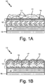
- FIGS. 1A-1B are schematic drawings of PDI 12 with attached pressure sensitive adhesive (PSA) layer 14.
- FIG. 1A shows pneumatic de-icer assembly 10 in a resting configuration
- FIG. 1B shows pneumatic de-icer assembly 10 in an activated configuration.
- FIGS. 1A-1B will be discussed together.
- the pneumatic de-icer assembly 10 includes pneumatic de-icer (PDI) 12, PSA layer 14 attached to PDI 12 on the bond side, and release liner 16 covering PSA layer 14.
- PDI pneumatic de-icer
- PDI 12 contains chambers 17, stiches 18, and spaces 19. Chambers 17 in PDI 12 inflates when PDI 12 is activated to mechanically remove ice 11. Stiches 18 define chambers 17 within PDI 12, and hold together all layers that make up PDI 12. Spaces 19 form in chambers 17 when PDI 12 is activated, resulting in mechanical upheaval and dislodging of ice 11 on PDI 12.
- PSA layer 14 is attached to PDI 12 opposite chambers 17 so that it is secured to the bond side (not the breeze side) of PDI 12.
- PSA layer 14 is an adhesive that forms a bond when pressure is applied to marry the adhesive with the surface to which it is being attached.
- suitable PSA materials include acrylic PSA or rubber based PSA, for instance, pn VHB 9473 by 3M ®.
- PSA layer 14 is attached to PDI 12 during manufacturing of PDI 12 by wetting out of the PSA layer 14 onto the surface of PDI 12.
- Release liner 16 cover PSA layer 14 opposite PDI 12. Release line 16 protects PSA layer 14 so that dust or other contaminants do not stick to PSA layer 12 prior to installation of assembly 10A onto an aircraft wing.
- Assembly 10 (in its non-activated state) is attached to an aircraft component, such as a wing, as shown in FIGS. 2A-2D .
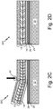
- FIGS. 2A-2D are schematic drawings showing a method of attaching a pneumatic de-icer onto an aircraft component in steps 20A - 20D.
- the aircraft component can be, for example, to the leading edge of a wing that will experience ice formation during flight, and will require pneumatic de-icers.
- the final assembly on wing skin 22 includes PSA primer 24, base PSA layer 26, and pneumatic de-icing assembly 10 as described in reference to FIGS. 1A-1B .
- Pneumatic de-icing assembly 10 includes both PDI 12 and PSA layer 14.
- wing skin 22 is prepared for adhesion of pneumatic de-icer assembly 10 with PSA primer 24.
- PSA primer 24 promotes adhesion between wing skin 22 and base PSA layer 26.
- PSA primer 24 can be, for example, pn 94 available from 3M ®.PSA primer 24 is applied evenly throughout wing skin 22, and can be applied by spraying, painting, wiping, or other appropriate methods.
- base PSA layer 26 is applied to wing skin 22 on top of primer 24.
- base PSA layer 26 is an adhesive that forms a bond when pressure is applied to marry the adhesive with the surface to which it is being attached.
- Base PSA layer 26 has a thickness of about 5 mils.
- PSA layer 26 is typically a rolled PSA layer 26 with release liner 28.
- Base PSA layer 26 is rolled out onto wing skin 22 such that release liner 28 is positioned opposite wing skin 22 as base PSA layer 26 is rolled out onto wing skin 22.
- Base PSA layer 26 can be, for example, laminated to wing skin 22.
- Hand roller 30 is used to "wet out” base PSA layer 26 to create a secure bond between wing skin 22 and base PSA layer 26. Applying pressure to PSA layer 26 creates a strong bond between wing skin 22 (including PSA primer 24).
- Base PSA layer 26 is very thin, and can be efficiently and evenly wetted out with hand roller 30.
- a heat gun can be used to warm base PSA layer 26 and promote wetting out during use of hand roller 30.
- pneumatic de-icer assembly 10 (including PSA layer 14 and PDI 12) is attached to base PSA layer 26 on wing skin 22 as shown by step 20C in FIG. 2C .
- PDI 12 is a pneumatic de-icing device that mechanically breaks up ice forming on an aircraft wing during flight, typically by inflating sections in PDI 12 as described in reference to FIGS. 1A-1B .
- PSA layer 14 is attached to PDI 12 on the non-activating side of PDI 12.
- PSA layer 14 can be, for example, laminated or rolled onto PDI 12 to secure PSA layer 14 during manufacturing.
- PSA layer 14, which has a thickness of about 5 mils, is wetted out to PDI 12 during the manufacturing process.
- Release liner 16 is secured on PSA layer 14 to prevent dust and contamination prior to application of PDI 12 and PSA layer 14 on wing skin 22.
- PDI 12 can be shipped with second PSA layer 24 attached.
- FIG. 2C PDI 12 with attached PSA layer 14 is bonded to base PSA layer 26.
- the release liner of PSA layer 14 is removed as pneumatic de-icer assembly 10 is attached to base PSA layer 26, and hand roller 30 is used to "wet out" PSA layer 14 as described in reference to FIG. 2B .
- Rolling first and second PSA layers 16, 22, into each other allows for better wetting out of both layers, and a secure, high energy PSA to PSA bond. This high energy bond prevents peeling or lifting of PDI 12 from wing skin 22.
- Finished assembly 20D shown in FIG. 2D includes wing skin 22, PSA primer 24, base PSA liner 26, PSA liner 14, and pneumatic de-icer 12.
- PSA layers 14, 26, can have differing thicknesses.
- the resulting PSA to PSA bond achieves maximum adhesion on contact. Both PSA surfaces are very high energy surfaces that bond well to each other. The use of hand roller 30 to wet out both PSA layers helps secure this bond.
- a method of attaching a pneumatic de-icer to an aircraft wing includes applying a pressure sensitive adhesive primer to a wing surface, attaching a first pressure sensitive adhesive layer to the wing surface through the pressure sensitive adhesive primer, attaching a second pressure sensitive adhesive layer to a pneumatic de-icer, and bonding the second pressure sensitive adhesive layer to the first pressure sensitive adhesive layer so that the pneumatic de-icer is attached to the wing surface by a pressure sensitive adhesive to pressure sensitive adhesive bond.
- the method of the preceding paragraph can optionally include, additionally and/or alternatively, any one or more of the following features, configurations and/or additional components: Applying a pressure sensitive adhesive primer to a wing surface is done by spraying, wiping, or painting.
- Attaching a first pressure sensitive adhesive layer to the wing surface is done with a hand roller.
- Attaching a first pressure sensitive adhesive layer to the wing surface is done by releasing a liner from the first pressure sensitive adhesive layer.
- Attaching a second pressure sensitive adhesive layer to a pneumatic de-icer is performed with a hand roller.
- Attaching a second pressure sensitive adhesive layer to a pneumatic de-icer is performed on a bond side of the pneumatic de-icer.
- Bonding the second pressure sensitive adhesive layer to the first pressure sensitive adhesive layer is performed with a hand roller.
- Bonding the second pressure sensitive adhesive layer to the first pressure sensitive adhesive layer comprises heating the first and second pressure adhesives.
- Bonding the second pressure sensitive adhesive layer to the first pressure sensitive adhesive layer is performed by releasing a liner on the second pressure sensitive adhesive layer.
- the first pressure sensitive adhesive layer and the second pressure sensitive adhesive layer each have a thickness of 5 mils.
- the first pressure sensitive adhesive layer and the second pressure sensitive adhesive layer are selected from the group consisting of acrylic pressure sensitive adhesive and rubber based pressure sensitive adhesive.
- the wing skin is a leading edge of an aircraft wing.
- the method includes cleaning the wing surface prior to applying the pressure sensitive adhesive primer.
- a pneumatic de-icing assembly includes a first pressure sensitive adhesive layer attached to a wing skin, a second pressure sensitive adhesive layer bonded to the first pressure sensitive adhesive layer opposite the wing skin, and a pneumatic de-icer attached to the second pressure sensitive adhesive layer opposite the first pressure sensitive adhesive layer wherein the pneumatic de-icer is s attached to the wing skin by a pressure sensitive adhesive to pressure sensitive adhesive bond.
- the assembly of the preceding paragraph can optionally include, additionally and/or alternatively, any one or more of the following features, configurations and/or additional components:
- the assembly includes a pressure sensitive adhesive primer between the first pressure sensitive adhesive layer and the wing skin.
- the pressure sensitive adhesive to pressure sensitive adhesive bond is a high energy bond.
- the first pressure sensitive adhesive layer and the second pressure sensitive adhesive layer each have a thickness of less than 10 mils.
- the first pressure sensitive adhesive layer and the second pressure sensitive adhesive layer each have a thickness of 5 mils.
- the first pressure sensitive adhesive layer and the second pressure sensitive adhesive layer have the same thickness.
Landscapes
- Engineering & Computer Science (AREA)
- Chemical & Material Sciences (AREA)
- Organic Chemistry (AREA)
- Mechanical Engineering (AREA)
- Aviation & Aerospace Engineering (AREA)
- Adhesives Or Adhesive Processes (AREA)
- Laminated Bodies (AREA)
Abstract
Description
- This application relates generally to ice protection technology, and specifically to pneumatic de-icer assemblies.
- Pneumatic de-icers for aircraft are bonded directly to an airframe, usually a wing, with varying types of adhesives. Pressure sensitive adhesives (PSAs) are frequently used, typically with a thickness in the range of about 10 mils. These types of PSAs are laminated to pneumatic de-icers during pneumatic de-icer manufacturing and shipped with release liners to prevent dust and contamination. The release liner on the PSA is removed when the pneumatic de-icer is applied to a wing surface.
- When the pneumatic de-icer is applied to the wing surface, a hand roller can be used to "wet out" the PSA adhesive for increased adhesion. However, during this application, it is difficult to develop enough pressure throughout the pneumatic de-icer construction. This is due in part to varying construction throughout the pneumatic de-icer, and due to the thickness of the pneumatic de-icer. Thus, some features of the pneumatic de-icer make it difficult to achieve uniform pressure and obtain a good "wetted out" surface with excellent adhesion. Because of this, some areas tend to lift or peel back from the wing after time passes.
- A method of attaching a pneumatic de-icer to an aircraft wing includes applying a pressure sensitive adhesive primer to a wing surface, attaching a first pressure sensitive adhesive layer to the wing surface through the pressure sensitive adhesive primer, attaching a second pressure sensitive adhesive layer to a pneumatic de-icer, and bonding the second pressure sensitive adhesive layer to the first pressure sensitive adhesive layer so that the pneumatic de-icer is attached to the wing surface by a pressure sensitive adhesive to pressure sensitive adhesive bond.
-
-
FIGS. 1A-1B are schematic drawings of a pneumatic de-icer with an attached pressure sensitive adhesive layer. -
FIGS. 2A-2D are schematic drawings showing a method of attaching a pneumatic de-icer onto an aircraft wing. - Using two layers of pressure sensitive adhesive (PSA) to attach a pneumatic de-icer (PDI) to an aircraft component allows for the creation of a high energy PSA to PSA bond. The PSA to PSA bond allows for full "wetting out" of the PSA adhesive layers and a strong bond that prevents peeling or lifting of the PDI off the aircraft component.
-
FIGS. 1A-1B are schematic drawings ofPDI 12 with attached pressure sensitive adhesive (PSA)layer 14.FIG. 1A showspneumatic de-icer assembly 10 in a resting configuration, whileFIG. 1B showspneumatic de-icer assembly 10 in an activated configuration.FIGS. 1A-1B will be discussed together. Thepneumatic de-icer assembly 10 includes pneumatic de-icer (PDI) 12,PSA layer 14 attached toPDI 12 on the bond side, andrelease liner 16 coveringPSA layer 14. - PDI 12 contains
chambers 17,stiches 18, andspaces 19.Chambers 17 inPDI 12 inflates when PDI 12 is activated to mechanically removeice 11.Stiches 18 definechambers 17 withinPDI 12, and hold together all layers that make upPDI 12.Spaces 19 form inchambers 17 whenPDI 12 is activated, resulting in mechanical upheaval and dislodging ofice 11 onPDI 12. -
PSA layer 14 is attached toPDI 12opposite chambers 17 so that it is secured to the bond side (not the breeze side) ofPDI 12.PSA layer 14 is an adhesive that forms a bond when pressure is applied to marry the adhesive with the surface to which it is being attached. Examples of suitable PSA materials include acrylic PSA or rubber based PSA, for instance, pn VHB 9473 by 3M ®.PSA layer 14 is attached toPDI 12 during manufacturing ofPDI 12 by wetting out of thePSA layer 14 onto the surface ofPDI 12.Release liner 16cover PSA layer 14 oppositePDI 12.Release line 16 protectsPSA layer 14 so that dust or other contaminants do not stick toPSA layer 12 prior to installation of assembly 10A onto an aircraft wing. Assembly 10 (in its non-activated state) is attached to an aircraft component, such as a wing, as shown inFIGS. 2A-2D . -
FIGS. 2A-2D are schematic drawings showing a method of attaching a pneumatic de-icer onto an aircraft component insteps 20A - 20D. The aircraft component can be, for example, to the leading edge of a wing that will experience ice formation during flight, and will require pneumatic de-icers. The final assembly onwing skin 22 includesPSA primer 24,base PSA layer 26, andpneumatic de-icing assembly 10 as described in reference toFIGS. 1A-1B .Pneumatic de-icing assembly 10 includes bothPDI 12 andPSA layer 14. - In
step 20A shown inFIG. 2A ,wing skin 22 is prepared for adhesion ofpneumatic de-icer assembly 10 withPSA primer 24.PSA primer 24 promotes adhesion betweenwing skin 22 andbase PSA layer 26.PSA primer 24 can be, for example, pn 94 available from 3M ®.PSA primer 24 is applied evenly throughoutwing skin 22, and can be applied by spraying, painting, wiping, or other appropriate methods. - Next, in
step 20B shown inFIG. 2B ,base PSA layer 26 is applied towing skin 22 on top ofprimer 24. LikePSA layer 14,base PSA layer 26 is an adhesive that forms a bond when pressure is applied to marry the adhesive with the surface to which it is being attached.Base PSA layer 26 has a thickness of about 5 mils.PSA layer 26 is typically a rolledPSA layer 26 withrelease liner 28.Base PSA layer 26 is rolled out ontowing skin 22 such thatrelease liner 28 is positionedopposite wing skin 22 asbase PSA layer 26 is rolled out ontowing skin 22.Base PSA layer 26 can be, for example, laminated towing skin 22. - As
base PSA layer 26 is rolled ontowing skin 22,Hand roller 30 is used to "wet out"base PSA layer 26 to create a secure bond betweenwing skin 22 andbase PSA layer 26. Applying pressure toPSA layer 26 creates a strong bond between wing skin 22 (including PSA primer 24).Base PSA layer 26 is very thin, and can be efficiently and evenly wetted out withhand roller 30. Optionally, a heat gun can be used to warmbase PSA layer 26 and promote wetting out during use ofhand roller 30. - After
base PSA layer 26 is applied towing skin 22, pneumatic de-icer assembly 10 (includingPSA layer 14 and PDI 12) is attached tobase PSA layer 26 onwing skin 22 as shown bystep 20C inFIG. 2C . PDI 12 is a pneumatic de-icing device that mechanically breaks up ice forming on an aircraft wing during flight, typically by inflating sections inPDI 12 as described in reference toFIGS. 1A-1B . - As detailed with reference to
FIGS. 1A-1B , whenPDI 12 is being manufactured,PSA layer 14 is attached toPDI 12 on the non-activating side ofPDI 12.PSA layer 14 can be, for example, laminated or rolled ontoPDI 12 to securePSA layer 14 during manufacturing.PSA layer 14, which has a thickness of about 5 mils, is wetted out toPDI 12 during the manufacturing process.Release liner 16 is secured onPSA layer 14 to prevent dust and contamination prior to application ofPDI 12 andPSA layer 14 onwing skin 22.PDI 12 can be shipped withsecond PSA layer 24 attached. - In
FIG. 2C ,PDI 12 with attachedPSA layer 14 is bonded to basePSA layer 26. The release liner ofPSA layer 14 is removed as pneumaticde-icer assembly 10 is attached to basePSA layer 26, andhand roller 30 is used to "wet out"PSA layer 14 as described in reference toFIG. 2B . Rolling first and second PSA layers 16, 22, into each other allows for better wetting out of both layers, and a secure, high energy PSA to PSA bond. This high energy bond prevents peeling or lifting ofPDI 12 fromwing skin 22. -
Finished assembly 20D shown inFIG. 2D includeswing skin 22,PSA primer 24,base PSA liner 26,PSA liner 14, andpneumatic de-icer 12. PSA layers 14, 26, each with a thickness of about 5 mils, replace a traditional single 10 millimeter PSA layer. Alternatively, PSA layers 14, 26, can have differing thicknesses. The resulting PSA to PSA bond achieves maximum adhesion on contact. Both PSA surfaces are very high energy surfaces that bond well to each other. The use ofhand roller 30 to wet out both PSA layers helps secure this bond. - The following are non-exclusive descriptions of possible embodiments of the present invention.
- A method of attaching a pneumatic de-icer to an aircraft wing includes applying a pressure sensitive adhesive primer to a wing surface, attaching a first pressure sensitive adhesive layer to the wing surface through the pressure sensitive adhesive primer, attaching a second pressure sensitive adhesive layer to a pneumatic de-icer, and bonding the second pressure sensitive adhesive layer to the first pressure sensitive adhesive layer so that the pneumatic de-icer is attached to the wing surface by a pressure sensitive adhesive to pressure sensitive adhesive bond.
- The method of the preceding paragraph can optionally include, additionally and/or alternatively, any one or more of the following features, configurations and/or additional components:
Applying a pressure sensitive adhesive primer to a wing surface is done by spraying, wiping, or painting. - Attaching a first pressure sensitive adhesive layer to the wing surface is done with a hand roller.
- Attaching a first pressure sensitive adhesive layer to the wing surface is done by releasing a liner from the first pressure sensitive adhesive layer.
- Attaching a second pressure sensitive adhesive layer to a pneumatic de-icer is performed with a hand roller.
- Attaching a second pressure sensitive adhesive layer to a pneumatic de-icer is performed on a bond side of the pneumatic de-icer.
- Bonding the second pressure sensitive adhesive layer to the first pressure sensitive adhesive layer is performed with a hand roller.
- Bonding the second pressure sensitive adhesive layer to the first pressure sensitive adhesive layer comprises heating the first and second pressure adhesives.
- Bonding the second pressure sensitive adhesive layer to the first pressure sensitive adhesive layer is performed by releasing a liner on the second pressure sensitive adhesive layer.
- The first pressure sensitive adhesive layer and the second pressure sensitive adhesive layer each have a thickness of 5 mils.
- The first pressure sensitive adhesive layer and the second pressure sensitive adhesive layer are selected from the group consisting of acrylic pressure sensitive adhesive and rubber based pressure sensitive adhesive.
- The wing skin is a leading edge of an aircraft wing.
- The method includes cleaning the wing surface prior to applying the pressure sensitive adhesive primer.
- A pneumatic de-icing assembly includes a first pressure sensitive adhesive layer attached to a wing skin, a second pressure sensitive adhesive layer bonded to the first pressure sensitive adhesive layer opposite the wing skin, and a pneumatic de-icer attached to the second pressure sensitive adhesive layer opposite the first pressure sensitive adhesive layer wherein the pneumatic de-icer is s attached to the wing skin by a pressure sensitive adhesive to pressure sensitive adhesive bond.
- The assembly of the preceding paragraph can optionally include, additionally and/or alternatively, any one or more of the following features, configurations and/or additional components:
The assembly includes a pressure sensitive adhesive primer between the first pressure sensitive adhesive layer and the wing skin. - The pressure sensitive adhesive to pressure sensitive adhesive bond is a high energy bond.
- The first pressure sensitive adhesive layer and the second pressure sensitive adhesive layer each have a thickness of less than 10 mils.
- The first pressure sensitive adhesive layer and the second pressure sensitive adhesive layer each have a thickness of 5 mils.
- The first pressure sensitive adhesive layer and the second pressure sensitive adhesive layer have the same thickness.
- While the invention has been described with reference to an exemplary embodiment(s), it will be understood by those skilled in the art that various changes may be made and equivalents may be substituted for elements thereof without departing from the scope of the invention. In addition, many modifications may be made to adapt a particular situation or material to the teachings of the invention without departing from the essential scope thereof. Therefore, it is intended that the invention not be limited to the particular embodiment(s) disclosed, but that the invention will include all embodiments falling within the scope of the appended claims.
Claims (15)
- A method of attaching a pneumatic de-icer to an aircraft wing comprises:applying a pressure sensitive adhesive primer (24) to a wing surface;attaching a first pressure sensitive adhesive layer (26) to the wing surface through the pressure sensitive adhesive primer;attaching a second pressure sensitive adhesive layer (14) to a pneumatic de-icer;bonding the second pressure sensitive adhesive layer to the first pressure sensitive adhesive layer so that the pneumatic de-icer is attached to the wing surface by a pressure sensitive adhesive to pressure sensitive adhesive bond.
- The method of claim 1, wherein applying a pressure sensitive adhesive primer to a wing surface is done by spraying, wiping, or painting, or wherein attaching a first pressure sensitive adhesive layer to the wing surface is done with a hand roller (30) or wherein attaching a first pressure sensitive adhesive layer to the wing surface is done by releasing a liner from the first pressure sensitive adhesive layer.
- The method of any preceding claim, wherein attaching a second pressure sensitive adhesive layer to a pneumatic de-icer is performed with a hand roller (30).
- The method of any preceding claim, wherein attaching a second pressure sensitive adhesive layer to a pneumatic de-icer is performed on a bond side of the pneumatic de-icer.
- The method of any preceding claim, wherein bonding the second pressure sensitive adhesive layer to the first pressure sensitive adhesive layer is performed with a hand roller.
- The method of any preceding claim, wherein bonding the second pressure sensitive adhesive layer to the first pressure sensitive adhesive layer comprises heating the first and second pressure adhesives.
- The method of any preceding claim, wherein bonding the second pressure sensitive adhesive layer to the first pressure sensitive adhesive layer is performed by releasing a liner on the second pressure sensitive adhesive layer.
- The method of any preceding claim, wherein the first pressure sensitive adhesive layer and the second pressure sensitive adhesive layer each have a thickness of 5 mils.
- The method of any preceding claim, wherein the first pressure sensitive adhesive layer and the second pressure sensitive adhesive layer are selected from the group consisting of acrylic pressure sensitive adhesive and rubber based pressure sensitive adhesive.
- The method of any preceding claim, wherein the wing surface is a wing skin (22) which is a leading edge of an aircraft wing.
- The method of any preceding claim, further comprising cleaning the wing surface prior to applying the pressure sensitive adhesive primer.
- A pneumatic de-icing assembly comprising:a first pressure sensitive adhesive layer (26) attached to a wing skin (22);a second pressure sensitive adhesive layer (14) bonded to the first pressure sensitive adhesive layer opposite the wing skin; anda pneumatic de-icer (12) attached to the second pressure sensitive adhesive layer opposite the first pressure sensitive adhesive layer wherein the pneumatic de-icer is s attached to the wing skin by a pressure sensitive adhesive to pressure sensitive adhesive bond.
- The assembly of claim 12, further comprising a pressure sensitive adhesive primer (24) between the first pressure sensitive adhesive layer and the wing skin.
- The assembly of claim 12, wherein the pressure sensitive adhesive to pressure sensitive adhesive bond is a high energy bond.
- The assembly of claim 12, wherein the first pressure sensitive adhesive layer and the second pressure sensitive adhesive layer each have a thickness of less than 10 mils, and preferably wherein the first pressure sensitive adhesive layer and the second pressure sensitive adhesive layer each have a thickness of 5 mils, and preferably wherein the first pressure sensitive adhesive layer and the second pressure sensitive adhesive layer have the same thickness.
Applications Claiming Priority (1)
| Application Number | Priority Date | Filing Date | Title |
|---|---|---|---|
| US15/872,129 US10703492B2 (en) | 2018-01-16 | 2018-01-16 | Adhesive lay-up and method for attaching pneumatic de-icers |
Publications (2)
| Publication Number | Publication Date |
|---|---|
| EP3511384A1 true EP3511384A1 (en) | 2019-07-17 |
| EP3511384B1 EP3511384B1 (en) | 2024-04-03 |
Family
ID=65033523
Family Applications (1)
| Application Number | Title | Priority Date | Filing Date |
|---|---|---|---|
| EP19152119.4A Active EP3511384B1 (en) | 2018-01-16 | 2019-01-16 | Method for attaching pneumatic de-icers |
Country Status (2)
| Country | Link |
|---|---|
| US (1) | US10703492B2 (en) |
| EP (1) | EP3511384B1 (en) |
Cited By (1)
| Publication number | Priority date | Publication date | Assignee | Title |
|---|---|---|---|---|
| US20190185168A1 (en) * | 2017-12-18 | 2019-06-20 | Goodrich Corporation | Sewn alternate inflate pneumatic de-icer |
Citations (2)
| Publication number | Priority date | Publication date | Assignee | Title |
|---|---|---|---|---|
| EP0980827A1 (en) * | 1998-08-19 | 2000-02-23 | The B.F. Goodrich Company | Pressure sensitive adhesive for mounting a deicer and method for mounting thereof |
| WO2012080830A2 (en) * | 2010-12-17 | 2012-06-21 | Aerazur S.A. | Aircraft de-icer systems and methods |
Family Cites Families (5)
| Publication number | Priority date | Publication date | Assignee | Title |
|---|---|---|---|---|
| US6352601B1 (en) | 1994-12-27 | 2002-03-05 | The B. F. Goodrich Company | Self-adhering ice protector |
| GB9918291D0 (en) * | 1999-08-03 | 1999-10-06 | Croda Int Plc | Cold sealable adhesive |
| US20030122037A1 (en) * | 2001-12-06 | 2003-07-03 | Hyde Robert William | Aircraft deicing system |
| US8398306B2 (en) * | 2005-11-07 | 2013-03-19 | Kraft Foods Global Brands Llc | Flexible package with internal, resealable closure feature |
| NZ591354A (en) * | 2010-02-26 | 2012-09-28 | Kraft Foods Global Brands Llc | A low-tack, UV-cured pressure sensitive acrylic ester based adhesive for reclosable packaging |
-
2018
- 2018-01-16 US US15/872,129 patent/US10703492B2/en active Active
-
2019
- 2019-01-16 EP EP19152119.4A patent/EP3511384B1/en active Active
Patent Citations (2)
| Publication number | Priority date | Publication date | Assignee | Title |
|---|---|---|---|---|
| EP0980827A1 (en) * | 1998-08-19 | 2000-02-23 | The B.F. Goodrich Company | Pressure sensitive adhesive for mounting a deicer and method for mounting thereof |
| WO2012080830A2 (en) * | 2010-12-17 | 2012-06-21 | Aerazur S.A. | Aircraft de-icer systems and methods |
Cited By (2)
| Publication number | Priority date | Publication date | Assignee | Title |
|---|---|---|---|---|
| US20190185168A1 (en) * | 2017-12-18 | 2019-06-20 | Goodrich Corporation | Sewn alternate inflate pneumatic de-icer |
| US10780983B2 (en) * | 2017-12-18 | 2020-09-22 | Goodrich Corporation | Sewn alternate inflate pneumatic de-icer |
Also Published As
| Publication number | Publication date |
|---|---|
| US20190217961A1 (en) | 2019-07-18 |
| EP3511384B1 (en) | 2024-04-03 |
| US10703492B2 (en) | 2020-07-07 |
Similar Documents
| Publication | Publication Date | Title |
|---|---|---|
| EP3513060B1 (en) | Wind turbine blade including protective cover | |
| MX2011003714A (en) | Method for treating an optical lens for the edging thereof. | |
| JP2015168428A (en) | Repair device and method for composite panel with conductive layer | |
| US20220072831A1 (en) | Car glass protection film having self-restoration performance | |
| EP3511384B1 (en) | Method for attaching pneumatic de-icers | |
| JP2026034779A (en) | Light-controlling film with adhesive layer and method for attaching light-controlling film with adhesive layer to glass surface | |
| EP3543138B1 (en) | Installation of pneumatic de-icers with vertically aligned carbon nanotubes | |
| US20130316121A1 (en) | Method for manufacturing an inner covering assembly on a member of a forming tool | |
| JP2001011403A (en) | Pressure-sensitive adhesive tape for coating and coating method using pressure-sensitive adhesive tape for coating | |
| US9944032B2 (en) | Method for manufacturing endless belt and endless belt | |
| JP6968759B2 (en) | Aircraft interior parts, their manufacturing methods, and their replacement methods | |
| KR20220067017A (en) | Manufacturing method of flame resisting exterior sheet and a flame resisting exterior sheet thereby | |
| US20180163096A1 (en) | Dry functional coating tape | |
| KR20130001375A (en) | Partial Adhesive Tape Manufacturing Method | |
| WO2016142966A1 (en) | Adhesive sheet | |
| JP2000265123A (en) | Marking film and composite marking film | |
| US20160298001A1 (en) | Adhesive tape | |
| CA3174028C (en) | Method for removing coatings from surfaces | |
| US20220195261A1 (en) | Permanent, self-adhering, self-lubricating, anti-wear composite system | |
| US8592258B2 (en) | Semiconductor package and method of attaching semiconductor dies to substrates | |
| JP2000318086A (en) | Interior finishing material sheet, interior finishing material using the same, its manufacture, and method for recyling the interior finish | |
| CN211815182U (en) | Anti-cracking release paper | |
| JP2000202976A (en) | Method of manufacturing decorative member and decorative panel for elevator | |
| KR200351725Y1 (en) | A car door's inner vinylsheet for preventive of dust and moisture | |
| KR20140143924A (en) | olefin decoration sheet and its manufacturing method |
Legal Events
| Date | Code | Title | Description |
|---|---|---|---|
| PUAI | Public reference made under article 153(3) epc to a published international application that has entered the european phase |
Free format text: ORIGINAL CODE: 0009012 |
|
| STAA | Information on the status of an ep patent application or granted ep patent |
Free format text: STATUS: THE APPLICATION HAS BEEN PUBLISHED |
|
| AK | Designated contracting states |
Kind code of ref document: A1 Designated state(s): AL AT BE BG CH CY CZ DE DK EE ES FI FR GB GR HR HU IE IS IT LI LT LU LV MC MK MT NL NO PL PT RO RS SE SI SK SM TR |
|
| AX | Request for extension of the european patent |
Extension state: BA ME |
|
| STAA | Information on the status of an ep patent application or granted ep patent |
Free format text: STATUS: REQUEST FOR EXAMINATION WAS MADE |
|
| 17P | Request for examination filed |
Effective date: 20191119 |
|
| RBV | Designated contracting states (corrected) |
Designated state(s): AL AT BE BG CH CY CZ DE DK EE ES FI FR GB GR HR HU IE IS IT LI LT LU LV MC MK MT NL NO PL PT RO RS SE SI SK SM TR |
|
| STAA | Information on the status of an ep patent application or granted ep patent |
Free format text: STATUS: EXAMINATION IS IN PROGRESS |
|
| 17Q | First examination report despatched |
Effective date: 20210818 |
|
| GRAP | Despatch of communication of intention to grant a patent |
Free format text: ORIGINAL CODE: EPIDOSNIGR1 |
|
| STAA | Information on the status of an ep patent application or granted ep patent |
Free format text: STATUS: GRANT OF PATENT IS INTENDED |
|
| P01 | Opt-out of the competence of the unified patent court (upc) registered |
Effective date: 20230922 |
|
| INTG | Intention to grant announced |
Effective date: 20231023 |
|
| GRAS | Grant fee paid |
Free format text: ORIGINAL CODE: EPIDOSNIGR3 |
|
| GRAA | (expected) grant |
Free format text: ORIGINAL CODE: 0009210 |
|
| STAA | Information on the status of an ep patent application or granted ep patent |
Free format text: STATUS: THE PATENT HAS BEEN GRANTED |
|
| AK | Designated contracting states |
Kind code of ref document: B1 Designated state(s): AL AT BE BG CH CY CZ DE DK EE ES FI FR GB GR HR HU IE IS IT LI LT LU LV MC MK MT NL NO PL PT RO RS SE SI SK SM TR |
|
| REG | Reference to a national code |
Ref country code: GB Ref legal event code: FG4D |
|
| REG | Reference to a national code |
Ref country code: CH Ref legal event code: EP |
|
| REG | Reference to a national code |
Ref country code: IE Ref legal event code: FG4D |
|
| REG | Reference to a national code |
Ref country code: DE Ref legal event code: R096 Ref document number: 602019049278 Country of ref document: DE |
|
| REG | Reference to a national code |
Ref country code: LT Ref legal event code: MG9D |
|
| REG | Reference to a national code |
Ref country code: NL Ref legal event code: MP Effective date: 20240403 |
|
| REG | Reference to a national code |
Ref country code: AT Ref legal event code: MK05 Ref document number: 1672319 Country of ref document: AT Kind code of ref document: T Effective date: 20240403 |
|
| PG25 | Lapsed in a contracting state [announced via postgrant information from national office to epo] |
Ref country code: NL Free format text: LAPSE BECAUSE OF FAILURE TO SUBMIT A TRANSLATION OF THE DESCRIPTION OR TO PAY THE FEE WITHIN THE PRESCRIBED TIME-LIMIT Effective date: 20240403 |
|
| PG25 | Lapsed in a contracting state [announced via postgrant information from national office to epo] |
Ref country code: NL Free format text: LAPSE BECAUSE OF FAILURE TO SUBMIT A TRANSLATION OF THE DESCRIPTION OR TO PAY THE FEE WITHIN THE PRESCRIBED TIME-LIMIT Effective date: 20240403 |
|
| PG25 | Lapsed in a contracting state [announced via postgrant information from national office to epo] |
Ref country code: IS Free format text: LAPSE BECAUSE OF FAILURE TO SUBMIT A TRANSLATION OF THE DESCRIPTION OR TO PAY THE FEE WITHIN THE PRESCRIBED TIME-LIMIT Effective date: 20240803 |
|
| PG25 | Lapsed in a contracting state [announced via postgrant information from national office to epo] |
Ref country code: BG Free format text: LAPSE BECAUSE OF FAILURE TO SUBMIT A TRANSLATION OF THE DESCRIPTION OR TO PAY THE FEE WITHIN THE PRESCRIBED TIME-LIMIT Effective date: 20240403 |
|
| PG25 | Lapsed in a contracting state [announced via postgrant information from national office to epo] |
Ref country code: HR Free format text: LAPSE BECAUSE OF FAILURE TO SUBMIT A TRANSLATION OF THE DESCRIPTION OR TO PAY THE FEE WITHIN THE PRESCRIBED TIME-LIMIT Effective date: 20240403 Ref country code: FI Free format text: LAPSE BECAUSE OF FAILURE TO SUBMIT A TRANSLATION OF THE DESCRIPTION OR TO PAY THE FEE WITHIN THE PRESCRIBED TIME-LIMIT Effective date: 20240403 |
|
| PG25 | Lapsed in a contracting state [announced via postgrant information from national office to epo] |
Ref country code: GR Free format text: LAPSE BECAUSE OF FAILURE TO SUBMIT A TRANSLATION OF THE DESCRIPTION OR TO PAY THE FEE WITHIN THE PRESCRIBED TIME-LIMIT Effective date: 20240704 |
|
| PG25 | Lapsed in a contracting state [announced via postgrant information from national office to epo] |
Ref country code: PT Free format text: LAPSE BECAUSE OF FAILURE TO SUBMIT A TRANSLATION OF THE DESCRIPTION OR TO PAY THE FEE WITHIN THE PRESCRIBED TIME-LIMIT Effective date: 20240805 |
|
| PG25 | Lapsed in a contracting state [announced via postgrant information from national office to epo] |
Ref country code: ES Free format text: LAPSE BECAUSE OF FAILURE TO SUBMIT A TRANSLATION OF THE DESCRIPTION OR TO PAY THE FEE WITHIN THE PRESCRIBED TIME-LIMIT Effective date: 20240403 |
|
| PG25 | Lapsed in a contracting state [announced via postgrant information from national office to epo] |
Ref country code: CZ Free format text: LAPSE BECAUSE OF FAILURE TO SUBMIT A TRANSLATION OF THE DESCRIPTION OR TO PAY THE FEE WITHIN THE PRESCRIBED TIME-LIMIT Effective date: 20240403 |
|
| PG25 | Lapsed in a contracting state [announced via postgrant information from national office to epo] |
Ref country code: AT Free format text: LAPSE BECAUSE OF FAILURE TO SUBMIT A TRANSLATION OF THE DESCRIPTION OR TO PAY THE FEE WITHIN THE PRESCRIBED TIME-LIMIT Effective date: 20240403 |
|
| PG25 | Lapsed in a contracting state [announced via postgrant information from national office to epo] |
Ref country code: PL Free format text: LAPSE BECAUSE OF FAILURE TO SUBMIT A TRANSLATION OF THE DESCRIPTION OR TO PAY THE FEE WITHIN THE PRESCRIBED TIME-LIMIT Effective date: 20240403 |
|
| PG25 | Lapsed in a contracting state [announced via postgrant information from national office to epo] |
Ref country code: LV Free format text: LAPSE BECAUSE OF FAILURE TO SUBMIT A TRANSLATION OF THE DESCRIPTION OR TO PAY THE FEE WITHIN THE PRESCRIBED TIME-LIMIT Effective date: 20240403 |
|
| PG25 | Lapsed in a contracting state [announced via postgrant information from national office to epo] |
Ref country code: PT Free format text: LAPSE BECAUSE OF FAILURE TO SUBMIT A TRANSLATION OF THE DESCRIPTION OR TO PAY THE FEE WITHIN THE PRESCRIBED TIME-LIMIT Effective date: 20240805 Ref country code: PL Free format text: LAPSE BECAUSE OF FAILURE TO SUBMIT A TRANSLATION OF THE DESCRIPTION OR TO PAY THE FEE WITHIN THE PRESCRIBED TIME-LIMIT Effective date: 20240403 Ref country code: NO Free format text: LAPSE BECAUSE OF FAILURE TO SUBMIT A TRANSLATION OF THE DESCRIPTION OR TO PAY THE FEE WITHIN THE PRESCRIBED TIME-LIMIT Effective date: 20240703 Ref country code: LV Free format text: LAPSE BECAUSE OF FAILURE TO SUBMIT A TRANSLATION OF THE DESCRIPTION OR TO PAY THE FEE WITHIN THE PRESCRIBED TIME-LIMIT Effective date: 20240403 Ref country code: IS Free format text: LAPSE BECAUSE OF FAILURE TO SUBMIT A TRANSLATION OF THE DESCRIPTION OR TO PAY THE FEE WITHIN THE PRESCRIBED TIME-LIMIT Effective date: 20240803 Ref country code: HR Free format text: LAPSE BECAUSE OF FAILURE TO SUBMIT A TRANSLATION OF THE DESCRIPTION OR TO PAY THE FEE WITHIN THE PRESCRIBED TIME-LIMIT Effective date: 20240403 Ref country code: GR Free format text: LAPSE BECAUSE OF FAILURE TO SUBMIT A TRANSLATION OF THE DESCRIPTION OR TO PAY THE FEE WITHIN THE PRESCRIBED TIME-LIMIT Effective date: 20240704 Ref country code: FI Free format text: LAPSE BECAUSE OF FAILURE TO SUBMIT A TRANSLATION OF THE DESCRIPTION OR TO PAY THE FEE WITHIN THE PRESCRIBED TIME-LIMIT Effective date: 20240403 Ref country code: ES Free format text: LAPSE BECAUSE OF FAILURE TO SUBMIT A TRANSLATION OF THE DESCRIPTION OR TO PAY THE FEE WITHIN THE PRESCRIBED TIME-LIMIT Effective date: 20240403 Ref country code: CZ Free format text: LAPSE BECAUSE OF FAILURE TO SUBMIT A TRANSLATION OF THE DESCRIPTION OR TO PAY THE FEE WITHIN THE PRESCRIBED TIME-LIMIT Effective date: 20240403 Ref country code: BG Free format text: LAPSE BECAUSE OF FAILURE TO SUBMIT A TRANSLATION OF THE DESCRIPTION OR TO PAY THE FEE WITHIN THE PRESCRIBED TIME-LIMIT Effective date: 20240403 Ref country code: AT Free format text: LAPSE BECAUSE OF FAILURE TO SUBMIT A TRANSLATION OF THE DESCRIPTION OR TO PAY THE FEE WITHIN THE PRESCRIBED TIME-LIMIT Effective date: 20240403 Ref country code: RS Free format text: LAPSE BECAUSE OF FAILURE TO SUBMIT A TRANSLATION OF THE DESCRIPTION OR TO PAY THE FEE WITHIN THE PRESCRIBED TIME-LIMIT Effective date: 20240703 |
|
| REG | Reference to a national code |
Ref country code: DE Ref legal event code: R097 Ref document number: 602019049278 Country of ref document: DE |
|
| PG25 | Lapsed in a contracting state [announced via postgrant information from national office to epo] |
Ref country code: DK Free format text: LAPSE BECAUSE OF FAILURE TO SUBMIT A TRANSLATION OF THE DESCRIPTION OR TO PAY THE FEE WITHIN THE PRESCRIBED TIME-LIMIT Effective date: 20240403 |
|
| PG25 | Lapsed in a contracting state [announced via postgrant information from national office to epo] |
Ref country code: EE Free format text: LAPSE BECAUSE OF FAILURE TO SUBMIT A TRANSLATION OF THE DESCRIPTION OR TO PAY THE FEE WITHIN THE PRESCRIBED TIME-LIMIT Effective date: 20240403 |
|
| PG25 | Lapsed in a contracting state [announced via postgrant information from national office to epo] |
Ref country code: SK Free format text: LAPSE BECAUSE OF FAILURE TO SUBMIT A TRANSLATION OF THE DESCRIPTION OR TO PAY THE FEE WITHIN THE PRESCRIBED TIME-LIMIT Effective date: 20240403 Ref country code: RO Free format text: LAPSE BECAUSE OF FAILURE TO SUBMIT A TRANSLATION OF THE DESCRIPTION OR TO PAY THE FEE WITHIN THE PRESCRIBED TIME-LIMIT Effective date: 20240403 |
|
| PG25 | Lapsed in a contracting state [announced via postgrant information from national office to epo] |
Ref country code: SM Free format text: LAPSE BECAUSE OF FAILURE TO SUBMIT A TRANSLATION OF THE DESCRIPTION OR TO PAY THE FEE WITHIN THE PRESCRIBED TIME-LIMIT Effective date: 20240403 |
|
| PG25 | Lapsed in a contracting state [announced via postgrant information from national office to epo] |
Ref country code: SM Free format text: LAPSE BECAUSE OF FAILURE TO SUBMIT A TRANSLATION OF THE DESCRIPTION OR TO PAY THE FEE WITHIN THE PRESCRIBED TIME-LIMIT Effective date: 20240403 Ref country code: SK Free format text: LAPSE BECAUSE OF FAILURE TO SUBMIT A TRANSLATION OF THE DESCRIPTION OR TO PAY THE FEE WITHIN THE PRESCRIBED TIME-LIMIT Effective date: 20240403 Ref country code: RO Free format text: LAPSE BECAUSE OF FAILURE TO SUBMIT A TRANSLATION OF THE DESCRIPTION OR TO PAY THE FEE WITHIN THE PRESCRIBED TIME-LIMIT Effective date: 20240403 Ref country code: EE Free format text: LAPSE BECAUSE OF FAILURE TO SUBMIT A TRANSLATION OF THE DESCRIPTION OR TO PAY THE FEE WITHIN THE PRESCRIBED TIME-LIMIT Effective date: 20240403 Ref country code: DK Free format text: LAPSE BECAUSE OF FAILURE TO SUBMIT A TRANSLATION OF THE DESCRIPTION OR TO PAY THE FEE WITHIN THE PRESCRIBED TIME-LIMIT Effective date: 20240403 |
|
| PLBE | No opposition filed within time limit |
Free format text: ORIGINAL CODE: 0009261 |
|
| STAA | Information on the status of an ep patent application or granted ep patent |
Free format text: STATUS: NO OPPOSITION FILED WITHIN TIME LIMIT |
|
| 26N | No opposition filed |
Effective date: 20250106 |
|
| PG25 | Lapsed in a contracting state [announced via postgrant information from national office to epo] |
Ref country code: SI Free format text: LAPSE BECAUSE OF FAILURE TO SUBMIT A TRANSLATION OF THE DESCRIPTION OR TO PAY THE FEE WITHIN THE PRESCRIBED TIME-LIMIT Effective date: 20240403 |
|
| REG | Reference to a national code |
Ref country code: CH Ref legal event code: PL |
|
| PG25 | Lapsed in a contracting state [announced via postgrant information from national office to epo] |
Ref country code: SE Free format text: LAPSE BECAUSE OF FAILURE TO SUBMIT A TRANSLATION OF THE DESCRIPTION OR TO PAY THE FEE WITHIN THE PRESCRIBED TIME-LIMIT Effective date: 20240403 |
|
| PG25 | Lapsed in a contracting state [announced via postgrant information from national office to epo] |
Ref country code: MC Free format text: LAPSE BECAUSE OF FAILURE TO SUBMIT A TRANSLATION OF THE DESCRIPTION OR TO PAY THE FEE WITHIN THE PRESCRIBED TIME-LIMIT Effective date: 20240403 Ref country code: LU Free format text: LAPSE BECAUSE OF NON-PAYMENT OF DUE FEES Effective date: 20250116 |
|
| PG25 | Lapsed in a contracting state [announced via postgrant information from national office to epo] |
Ref country code: BE Free format text: LAPSE BECAUSE OF NON-PAYMENT OF DUE FEES Effective date: 20250131 |
|
| PG25 | Lapsed in a contracting state [announced via postgrant information from national office to epo] |
Ref country code: CH Free format text: LAPSE BECAUSE OF NON-PAYMENT OF DUE FEES Effective date: 20250131 |
|
| REG | Reference to a national code |
Ref country code: BE Ref legal event code: MM Effective date: 20250131 |
|
| PGFP | Annual fee paid to national office [announced via postgrant information from national office to epo] |
Ref country code: GB Payment date: 20251220 Year of fee payment: 8 |
|
| PGFP | Annual fee paid to national office [announced via postgrant information from national office to epo] |
Ref country code: FR Payment date: 20251218 Year of fee payment: 8 |
|
| PG25 | Lapsed in a contracting state [announced via postgrant information from national office to epo] |
Ref country code: IE Free format text: LAPSE BECAUSE OF NON-PAYMENT OF DUE FEES Effective date: 20250116 |
|
| PG25 | Lapsed in a contracting state [announced via postgrant information from national office to epo] |
Ref country code: IT Free format text: LAPSE BECAUSE OF FAILURE TO SUBMIT A TRANSLATION OF THE DESCRIPTION OR TO PAY THE FEE WITHIN THE PRESCRIBED TIME-LIMIT Effective date: 20240403 |
|
| PGFP | Annual fee paid to national office [announced via postgrant information from national office to epo] |
Ref country code: DE Payment date: 20251217 Year of fee payment: 8 |