EP3511030A1 - Aspiration and discharge unit and aspiration and discharge device - Google Patents
Aspiration and discharge unit and aspiration and discharge device Download PDFInfo
- Publication number
- EP3511030A1 EP3511030A1 EP17876512.9A EP17876512A EP3511030A1 EP 3511030 A1 EP3511030 A1 EP 3511030A1 EP 17876512 A EP17876512 A EP 17876512A EP 3511030 A1 EP3511030 A1 EP 3511030A1
- Authority
- EP
- European Patent Office
- Prior art keywords
- chamber
- liquid
- pressure
- unit
- negative pressure
- Prior art date
- Legal status (The legal status is an assumption and is not a legal conclusion. Google has not performed a legal analysis and makes no representation as to the accuracy of the status listed.)
- Granted
Links
Images





Classifications
-
- A—HUMAN NECESSITIES
- A61—MEDICAL OR VETERINARY SCIENCE; HYGIENE
- A61M—DEVICES FOR INTRODUCING MEDIA INTO, OR ONTO, THE BODY; DEVICES FOR TRANSDUCING BODY MEDIA OR FOR TAKING MEDIA FROM THE BODY; DEVICES FOR PRODUCING OR ENDING SLEEP OR STUPOR
- A61M1/00—Suction or pumping devices for medical purposes; Devices for carrying-off, for treatment of, or for carrying-over, body-liquids; Drainage systems
- A61M1/60—Containers for suction drainage, adapted to be used with an external suction source
- A61M1/61—Two- or three-bottle systems for underwater drainage, e.g. for chest cavity drainage
-
- A—HUMAN NECESSITIES
- A61—MEDICAL OR VETERINARY SCIENCE; HYGIENE
- A61M—DEVICES FOR INTRODUCING MEDIA INTO, OR ONTO, THE BODY; DEVICES FOR TRANSDUCING BODY MEDIA OR FOR TAKING MEDIA FROM THE BODY; DEVICES FOR PRODUCING OR ENDING SLEEP OR STUPOR
- A61M1/00—Suction or pumping devices for medical purposes; Devices for carrying-off, for treatment of, or for carrying-over, body-liquids; Drainage systems
-
- A—HUMAN NECESSITIES
- A61—MEDICAL OR VETERINARY SCIENCE; HYGIENE
- A61M—DEVICES FOR INTRODUCING MEDIA INTO, OR ONTO, THE BODY; DEVICES FOR TRANSDUCING BODY MEDIA OR FOR TAKING MEDIA FROM THE BODY; DEVICES FOR PRODUCING OR ENDING SLEEP OR STUPOR
- A61M1/00—Suction or pumping devices for medical purposes; Devices for carrying-off, for treatment of, or for carrying-over, body-liquids; Drainage systems
- A61M1/60—Containers for suction drainage, adapted to be used with an external suction source
-
- A—HUMAN NECESSITIES
- A61—MEDICAL OR VETERINARY SCIENCE; HYGIENE
- A61M—DEVICES FOR INTRODUCING MEDIA INTO, OR ONTO, THE BODY; DEVICES FOR TRANSDUCING BODY MEDIA OR FOR TAKING MEDIA FROM THE BODY; DEVICES FOR PRODUCING OR ENDING SLEEP OR STUPOR
- A61M1/00—Suction or pumping devices for medical purposes; Devices for carrying-off, for treatment of, or for carrying-over, body-liquids; Drainage systems
- A61M1/71—Suction drainage systems
- A61M1/74—Suction control
-
- A—HUMAN NECESSITIES
- A61—MEDICAL OR VETERINARY SCIENCE; HYGIENE
- A61B—DIAGNOSIS; SURGERY; IDENTIFICATION
- A61B2217/00—General characteristics of surgical instruments
- A61B2217/002—Auxiliary appliance
- A61B2217/005—Auxiliary appliance with suction drainage system
-
- A—HUMAN NECESSITIES
- A61—MEDICAL OR VETERINARY SCIENCE; HYGIENE
- A61M—DEVICES FOR INTRODUCING MEDIA INTO, OR ONTO, THE BODY; DEVICES FOR TRANSDUCING BODY MEDIA OR FOR TAKING MEDIA FROM THE BODY; DEVICES FOR PRODUCING OR ENDING SLEEP OR STUPOR
- A61M2205/00—General characteristics of the apparatus
- A61M2205/33—Controlling, regulating or measuring
- A61M2205/3331—Pressure; Flow
- A61M2205/3341—Pressure; Flow stabilising pressure or flow to avoid excessive variation
-
- A—HUMAN NECESSITIES
- A61—MEDICAL OR VETERINARY SCIENCE; HYGIENE
- A61M—DEVICES FOR INTRODUCING MEDIA INTO, OR ONTO, THE BODY; DEVICES FOR TRANSDUCING BODY MEDIA OR FOR TAKING MEDIA FROM THE BODY; DEVICES FOR PRODUCING OR ENDING SLEEP OR STUPOR
- A61M2205/00—General characteristics of the apparatus
- A61M2205/33—Controlling, regulating or measuring
- A61M2205/3331—Pressure; Flow
- A61M2205/3348—Pressure measurement using a water column
-
- A—HUMAN NECESSITIES
- A61—MEDICAL OR VETERINARY SCIENCE; HYGIENE
- A61M—DEVICES FOR INTRODUCING MEDIA INTO, OR ONTO, THE BODY; DEVICES FOR TRANSDUCING BODY MEDIA OR FOR TAKING MEDIA FROM THE BODY; DEVICES FOR PRODUCING OR ENDING SLEEP OR STUPOR
- A61M2210/00—Anatomical parts of the body
- A61M2210/10—Trunk
Definitions
- the present invention relates to a suction discharge unit and a suction discharge device.
- suction discharge devices that suck a bodily fluid or gas from a body cavity such as the chest of a subject after surgery by using the suction pressure of a continuously operating suction source are known(for example, refer to Patent Document 1).
- a liquid such as a sucked bodily fluid (hereafter, bodily fluid and the like) is stored in a transparent resin container (waste liquid container) called a suction bottle or a suction bag, and is then detached from the suction source at a suitable time and discarded.
- This type of waste liquid container is used such that a downstream space that is connected to the suction source and is subjected to negative pressure suction and an upstream space into which a bodily fluid and the like flows are isolated from each other, and such that the two spaces are water sealed from each other using sterile water.
- Patent Document 1 Japanese Unexamined Patent Application Publication No. 7-213599
- the negative pressure inside the chest cavity or inside a container (storage chamber) of the suction discharge device connected to the inside of the chest cavity may become excessive.
- Such a negative pressure will damage the cellular tissues inside the body of the subject. Therefore, it is necessary for the nurse who is on duty to perform an operation to release the negative pressure of the container.
- the present invention has been made in order to solve the above-described problem, and it is an object thereof to provide a suction discharge unit and a suction discharge device that are able to automatically prevent a negative pressure inside a storage chamber and a first chamber from becoming excessively large.
- a suction discharge unit that solves the above-described problem is disposed between a subject and a suction source.
- the suction discharge unit includes: a first connection hole that communicates with the subject; a second connection hole that communicates with the suction source; a storage chamber that stores a first liquid that flows thereinto from the first connection hole; a water sealing chamber including a first chamber that communicates with the storage chamber and into which passage of the first liquid is prevented by a first partition wall and a second chamber that is isolated from the first chamber by a water sealing part and a second partition wall and that is connected to the suction source via the second connection hole; and a negative pressure control unit that controls a pressure of the first chamber by causing gas to flow from the second chamber to the first chamber on the basis of a pressure of the second chamber and the pressure of the first chamber.
- the negative pressure control unit includes a liquid retaining part that is able to retain a second liquid and is disposed such that the pressure of the second chamber acts on the second liquid, and a control member having a control hole for controlling inflow of the gas on the basis of surface tension of the second liquid.
- the second liquid flows to the first chamber side of the control member via the control hole of the control member due to the pressure difference between the first chamber, which communicates with the storage chamber, and the second chamber.
- the pressure of the second chamber also acts on the inflowing second liquid via the control hole. Therefore, gas in the second chamber flows to the first chamber side of the control member via the control hole, turns into bubbles and passes through the second liquid due to the pressure difference between the first chamber and the second chamber. That is, gas in the second chamber flows into the first chamber via the negative pressure control unit.
- the negative pressure of the first chamber that is, the negative pressure of the storage chamber is reduced by this inflow of gas.
- the negative pressure control unit includes a support tube that has a first end portion, the entire edge of the control member being attached to an inner periphery of the first end portion, and a second end portion that is open to the first chamber, the first end portion being disposed in the liquid retaining part.
- the negative pressure control unit stops the gas from flowing from the second chamber to the first chamber when the value of a sum of the pressure of the first chamber, a liquid pressure generated by the weight of the second liquid contained inside the support tube, and a surface tension of the second liquid is equal to the pressure of the second chamber.
- the pressure of the storage chamber which communicates with the first chamber, can be controlled to a pressure corresponding to the liquid pressure generated by the weight of the second liquid and the pressure of the second chamber.
- the pressure of the storage chamber which communicates with the first chamber, can be controlled to a pressure in accordance with the diameter of the control hole, the density, height, and surface tension coefficient of the second liquid.
- the negative pressure control unit is accommodated in the second chamber. According to this configuration, as a result of the negative pressure control unit being accommodated in the second chamber, there is no need to connect a pipeline or the like to the outside in order to allow gas in the second chamber to flow from the second chamber to the first chamber via the negative pressure control unit, an increase in the size of the suction discharge unit can be suppressed.
- the above-described suction discharge unit includes a control unit that communicates with the first chamber and the second chamber and that accommodates the negative pressure control unit. According to this configuration, a control unit in which the negative pressure control unit is accommodated is connected to the unit that includes the storage chamber and the water sealing chamber, and consequently, it is possible to reduce the negative pressure in the storage chamber and to easily confirm the generation of an excessive negative pressure.
- the above-described suction discharge unit includes a filter between the storage chamber and the suction source. According to this configuration, bacteria can be prevented from entering a connection tube from the outside air by using a filter that does not allow bacteria or the like to pass therethrough as the filter.
- the above-described suction discharge unit includes a pressure adjusting chamber that has a second connection hole that communicates with the suction source, and the pressure adjusting chamber communicates with the second chamber via a connection pipe and adjusts the pressure of the second chamber.
- the pressure of the second chamber can be adjusted by the pressure adjusting chamber and the pressure of the first chamber and the storage chamber when suction is performed and the pressure of the first chamber and the storage chamber after an excessive pressure has been reduced can be set on the basis of the pressure of the second chamber.
- the above-described suction discharge unit further includes: a liquid passage hole that is provided in the negative pressure control unit, that allows liquid retained on the first chamber side of the control member to flow into the liquid retaining part, and that has a larger opening area than the control hole; a valve body that can switch the liquid passage hole between a sealed state and an open state; and an urging member that is connected to the valve body and urges the valve body in a direction so as to seal the liquid passage hole.
- the liquid passage hole of a fixed member is put into an open state by the valve body, and as a result liquid retained in the support tube flows into the liquid retaining part via the liquid passage hole and the negative pressure control unit is reset to the initial state.
- liquid is retained in the support tube, and therefore it is possible to confirm from this retained liquid that an excessive negative pressure has been generated again in the storage chamber.
- the liquid passage hole is positioned at an identical height as the control hole or at a lower height than the control hole in a height direction.
- liquid retained above the control member flows into the liquid retaining part from the liquid passage hole and does not remain above the control member.
- the above-described suction discharge unit further includes a seal releasing member that is connected to or contacts the valve body and can be operated so as to release a sealed state of the liquid passage hole realized by the valve body.
- a sealed state of the liquid passage hole can be easily released by operating the valve body using the seal releasing member.
- the urging member has elasticity, and the seal releasing member releases the sealed state of the control hole realized by the valve body by causing the urging member to elastically deform.
- the valve body when operation of the seal releasing member is stopped, the valve body is urged in a direction so as to seal the liquid passage hole of the fixed member by the elastic force of the urging member and the liquid passage hole is thus easily put into a sealed state.
- the seal releasing member is a pressing member that presses the valve body and thereby releases the sealed state of the control hole realized by the valve body.
- the sealed state of the liquid passage hole of the fixed member can be easily released by operating the valve body using the seal releasing member, which is a pressing member.
- the seal releasing member is a separating member that separates the valve body from the control hole and thereby releases the sealed state of the control hole realized by the valve body.
- the sealed state of the liquid passage hole of the fixed member can be easily released by operating the valve body using the seal releasing member, which is a separating member.
- a suction discharge device that solves the above-described problem includes: any one of the above-described suction discharge units; and a suction source that is connected to the suction discharge unit.
- a suction discharge device 10 includes a suction discharge unit 11 and a suction pump 12 functioning as a suction source.
- the suction discharge unit 11 is connected to a subject via a connection tube 13.
- the leading end of the connection tube 13 is inserted into the inside of the chest cavity of a patient who is the subject.
- the suction discharge unit 11 is connected to the suction pump 12 via the connection pipe 25.
- the suction pump 12 generates a negative pressure inside the suction discharge unit 11.
- the suction discharge unit 11 includes a first unit 21 and a second unit 22.
- the first unit 21 and the second unit 22 are connected to each other by a connection pipe 25.
- the suction pump 12 is connected to the connection pipe 25 via a connection pipe 14.
- the suction pump 12 is connected to the first unit 21 and the second unit 22.
- the first unit 21 is, for example, formed in a box-like shape and includes a bottom plate part 31a, a side wall part 31b, and a top part 31c.
- the side wall part 31b is formed in a cylindrical shape
- the bottom plate part 31a closes the lower end of the cylindrical side wall part 31b
- the top part 31c closes the upper end of the cylindrical side wall part 31b.
- a transparent material such as a transparent plastic is used as the material of the first unit 21 such that the inside of the first unit 21 can be observed from the outside.
- the internal space of the first unit 21 is divided into a storage chamber 41 and a water sealing chamber 42 by a first partition wall 32.
- the first partition wall 32 is connected to the bottom plate part 31a and the side wall part 31b and an upper end 32a of the first partition wall 32 is spaced apart from the top part 31c. Therefore, the storage chamber 41 and the water sealing chamber 42 communicate with each other in the upper part of the first unit 21 and a gas is able to move between the storage chamber 41 and the water sealing chamber 42.
- a first connection hole 34 that allows communication between the storage chamber 41 and the space outside the unit is formed in the top part 31c.
- the connection tube 13 is connected to the first connection hole 34.
- the connection tube 13 is connected to a connection pipe (not illustrated) formed in the upper surface of the first unit 21.
- the first connection hole 34 allows communication between the inside of the storage chamber 41 and the inside of the connection tube 13, in other words, the chest cavity of the subject.
- the water sealing chamber 42 is divided into a first chamber 42a and a second chamber 42b by a second partition wall 33.
- the second partition wall 33 is connected to the top part 31c and the side wall part 31b and a lower end 33a of the second partition wall 33 is spaced apart from the bottom plate part 31a. Therefore, the first chamber 42a and the second chamber 42b communicate with each other in a lower part of the first unit 21.
- the internal space of the first unit 21 is divided into the storage chamber 41 and the water sealing chamber 42 by the first partition wall 32.
- the water sealing chamber 42 is divided into the first chamber 42a and the second chamber 42b by the second partition wall 33.
- connection pipe 25 is connected to the second connection hole 35.
- connection pipe 25 is connected to a connection pipe (not illustrated) formed in the upper surface of the first unit 21.
- the second connection hole 35 allows communication between the inside of the second chamber 42b and the inside of the connection pipe 25.
- a filter 45a is disposed in the connection pipe 14.
- the filter 45a is a hydrophobic filter.
- the filter 45a allows a gas to pass therethrough and does not allow a liquid to pass therethrough. Therefore, the filter 45a prevents a liquid from entering the suction pump 12, which functions as a suction source.
- a filter 45b is disposed in the connection pipe 25.
- the filter 45b is a bacteria filter that does not allow bacteria and the like to pass therethrough.
- the filter 45b is provided in order to prevent entry of bacteria into the connection tube 13 from the outside air. Therefore, it is sufficient that the filter 45b be provided closer to the outside air than the connection tube 13, and in this embodiment, the filter 45b is disposed in the connection pipe 25.
- Sealing water 36 serving as a water sealing part, is accommodated in the water sealing chamber 42.
- the sealing water 36 is sterile water.
- the sealing water 36 may be colored.
- the sealing water 36 is stored in the water sealing chamber 42 such that the water surface in the first chamber 42a and the water surface in the second chamber 42b are higher than the lower end 33a of the second partition wall 33 in a state where the suction pump 12 is not operating.
- the first unit 21 has a negative pressure control unit 50.
- the negative pressure control unit 50 is accommodated in the second chamber 42b of the water sealing chamber 42.
- the negative pressure control unit 50 includes a liquid retaining part 51, a control member 52, and a support tube 53.
- the liquid retaining part 51 is disposed at a prescribed position using a support member, which is not illustrated.
- the liquid retaining part 51 is fixed to the support tube 53, which will be described later, via the support member, which is not illustrated.
- the liquid retaining part 51 may be fixed in place using an inner wall of the second chamber 42b via a support member.
- the liquid retaining part 51 is formed so as to be able to retain a liquid 54.
- the liquid 54 is sterile water similarly to the sealing water 36 described above.
- the liquid 54 may be colored.
- the pressure inside the second chamber 42b acts on the liquid 54.
- the liquid 54 retained in the liquid retaining part 51 is supplied at the same time as the sealing water 36 in the water sealing chamber 42, for example.
- the liquid 54 is supplied to the liquid retaining part 51.
- the liquid 54 that overflows from the liquid retaining part 51 is retained in the water sealing chamber 42 as the sealing water 36.
- the control member 52 is formed to have a plate-like shape.
- the control member 52 includes control holes 52X that penetrate through the control member 52 in the thickness direction (up-down direction in figure).
- the control holes 52X are formed so as to have a prescribed shape.
- the control holes 52X are formed in a polygonal shape such as a triangular shape or one with a greater number of sides, or a circular shape or an elliptical shape, for example.
- the control member 52 is suitably formed in order to control the surface tension of the liquid 54 described above.
- the thickness of the control member 52 may be 20 ⁇ m, for example.
- the size of the control holes 52X can be 10-100 ⁇ m.
- the control member 52 is fixed in place inside the support tube 53.
- the control member 52 is supported so as to contact the liquid 54 retained in the liquid retaining part 51.
- the control member 52 is fixed to a leading end 53a of the support tube 53 and the leading end 53a of the support tube 53 is disposed inside the liquid retaining part 51. More specifically, the leading end 53a of the support tube 53 is disposed inside the liquid 54 retained in the liquid retaining part 51.
- a base end 53b of the support tube 53 is connected to the second partition wall 33.
- An opening 33b is formed in the second partition wall 33 and the inside of the first chamber 42a and the inside of the support tube 53 communicate with each other via the opening 33b.
- the control member 52 is disposed between the first chamber 42a and the second chamber 42b and the liquid 54 retained in the liquid retaining part 51 is disposed in the second chamber 42b.
- the inner space of the second unit 22 functions as a pressure adjusting chamber 43 that adjusts the pressure (negative pressure) inside the first unit 21.
- the second unit 22 is, for example, formed in a box-like shape and includes a bottom plate part 61a, a side wall part 61b, and a top part 61c.
- the side wall part 61b is formed in a cylindrical shape
- the bottom plate part 61a closes the lower end of the cylindrical side wall part 61b
- the top part 61c closes the upper end of the cylindrical side wall part 61b.
- a transparent material such as a transparent plastic is used as the material of the second unit 22 such that the inside of the second unit 22 can be observed from the outside.
- a third connection hole 63 that allows communication between the inside of the second unit 22 and the outside is formed in the top part 61c of the second unit 22.
- the connection pipe 25 is connected to the third connection hole 63.
- the connection pipe 25 is connected to a connection pipe (not illustrated) formed in the upper surface of the second unit 22.
- the third connection hole 63 allows communication between the inside of the second unit 22 and the inside of the connection pipe 25.
- This connection pipe allows communication between the inside of the second unit 22 and the water sealing chamber 42 (second chamber 42b) of the first unit 21.
- the second unit 22 includes a thin pipe 65.
- the upper end of the thin pipe 65 protrudes upward from the top part 61c and the inside of the thin pipe 65 is open to the atmosphere via an opening 65a in the upper end of the thin pipe 65.
- the lower end of the thin pipe 65 is positioned in the vicinity of the bottom plate part 61a.
- the second unit 22 controls the pressure acting in the second chamber 42b of the water sealing chamber 42 via the depth of sterile water 67.
- the inside of the second unit 22 When the inside of the second unit 22 is made to have a negative pressure by the suction pump 12, the inside of the second unit 22 is maintained at a negative pressure corresponding to the height of the water surface of the sterile water 67.
- the inner space of the second unit 22 communicates with the inside of the first unit 21 and the second chamber 42b of the water sealing chamber 42 via the connection pipe 25. Therefore, the second unit 22 (pressure adjusting chamber 43) adjusts the pressure inside the first unit 21.
- the second unit 22 (pressure adjusting chamber 43) adjusts the pressure of the second chamber 42b to a prescribed pressure (for example, -10 hPa from the atmospheric pressure).
- the storage chamber 41 comes to have a prescribed negative pressure (for example, -8 hPa from the atmospheric pressure).
- the negative pressure of the storage chamber 41 is maintained by the suction pump 12 and the pressure adjusting chamber 43, and a suction force is applied to the chest cavity of the subject via the connection tube 13.
- Discharge liquid and gas such as air is guided from the chest cavity of the subject to the storage chamber 41 via the connection tube 13 and the discharge liquid is stored in the storage chamber 41.
- the gas passes under the lower end 33a of the second partition wall 33 from the first chamber 42a of the water sealing chamber 42, which communicates with the storage chamber 41, becomes air bubbles inside the sealing water 36, and reaches the second chamber 42b.
- the negative pressure inside the storage chamber 41 may become excessive (for example, -40 hPa from the atmospheric pressure) as a result of the subject coughing or the like.
- the water level of the sealing water 36 in the first chamber 42a rises and the water level in the second chamber 42b falls due to the negative pressure inside the storage chamber 41.
- the liquid 54 in the liquid retaining part 51 of the negative pressure control unit 50 flows into the support tube 53 via the control member 52 due to the pressure difference between the pressure of the storage chamber 41 (first chamber 42a) and the pressure of the second chamber 42b.
- gas inside the second chamber 42b flows into the inside of the support tube 53 via the control holes 52X of the control member 52, turns into the bubbles 71, and passes through the liquid 54.
- the negative pressure control unit 50 causes the gas inside the second chamber 42b to flow into the first chamber 42a (storage chamber 41) due to the pressure of the first chamber 42a (storage chamber 41) and the pressure of the second chamber 42b.
- the pressure inside the storage chamber 41 rises and the excessive negative pressure is relieved by the gas being supplied to the storage chamber 41 from the second chamber 42b via the first chamber 42a.
- the liquid 54 is retained in the liquid retaining part 51 in an initial state (state where the negative pressure of storage chamber 41 is appropriate as illustrated in Fig. 1 ).
- the control holes 52X have a circular shape in this embodiment.
- R represents the diameter of the control holes 52X.
- ⁇ represents the density of the liquid 54
- ⁇ represents the surface tension coefficient of the liquid 54
- h represents the height of the liquid 54 retained in the support tube 53
- g represents the acceleration due to gravity.
- P1 represents the pressure of the first chamber 42a
- P2 represents the pressure of the second chamber 42b
- P 1 + ⁇ ⁇ gh + ⁇ / R P 2 in the state illustrated in part (f) of Fig. 4 . Therefore, the pressure of the storage chamber 41, which communicates with the first chamber 42a, can be controlled to a pressure according to the diameter R of the control holes 52X and the density ⁇ , height h, and surface tension coefficient ⁇ of the liquid 54.
- the suction discharge device 10 includes the suction discharge unit 11 and the suction pump 12.
- the suction discharge unit 11 includes the first unit 21 and the second unit 22.
- the second unit 22 controls the pressure inside the first unit 21.
- the first unit 21 includes the storage chamber 41 and the water sealing chamber 42.
- the water sealing chamber 42 includes the first chamber 42a, which communicates with the storage chamber 41, and the second chamber 42b, which is sealed from the first chamber 42a by the sealing water 36.
- the negative pressure control unit 50 is disposed in the second chamber 42b.
- the negative pressure control unit 50 includes the liquid retaining part that retains the liquid 54, the control member 52 that includes the control holes 52X, and the support tube 53 that supports the control member 52.
- the liquid 54 flows into the inside of the support tube 53 via the control holes 52X of the control member 52 due to the pressure difference between the first chamber 42a, which communicates with the storage chamber 41, and the second chamber 42b.
- the pressure of the second chamber 42b also acts on the liquid 54 inside support tube 53 via the control holes 52X. Therefore, gas in the second chamber 42b flows into the inside of the support tube 53 via the control holes 52X, turns into the bubbles 71, and passes through the liquid 54 due to the pressure difference between the first chamber 42a and the second chamber 42b.
- gas in the second chamber 42b flows into the first chamber 42a via the negative pressure control unit 50.
- the negative pressure of the first chamber 42a that is, the negative pressure of the storage chamber 41 can be reduced by this inflow of gas.
- it is possible to automatically prevent the negative pressure of the storage chamber 41 and the first chamber 42a from becoming excessively large.
- the first embodiment may be implemented in the following ways.
- a suction discharge unit 11a of a suction discharge device 10a includes the first unit 21, the second unit 22, and a third unit 23.
- the first unit 21 includes the storage chamber 41 and the water sealing chamber 42 and the water sealing chamber 42 includes the first chamber 42a and the second chamber 42b.
- the second unit 22 communicates with the first unit 21, and the second unit 22 is connected to the suction pump 12 and adjusts the pressure of the first unit 21.
- the third unit 23 is, for example, formed in a box-like shape and includes a bottom plate part 81a, a side wall part 81b, and a top part 81c.
- a transparent material such as a transparent plastic is used as the material of the third unit 23 such that the inside of the third unit 23 can be observed from the outside.
- the liquid 54 is retained in the third unit 23.
- a cap which is not illustrated, is provided in a top part of the third unit 23 and the liquid 54 is made to be retained inside the third unit 23 by opening and closing the cap.
- the support tube 53 is inserted into the inside of the third unit 23 from the top part 81c of the third unit 23, and the control member 52 is attached to the inside of the support tube 53.
- third unit 23 constitutes a negative pressure control unit.
- the support tube 53 communicates with the first chamber 42a via a connection pipe 26 between the third unit 23 and the first unit 21.
- the inside of the third unit 23 communicates with the second chamber 42b via a connection pipe 27 and the connection pipe 25.
- the pressure of the second chamber 42b acts on the liquid 54 retained in the liquid retaining part 51 via the connection pipe 27 and the connection pipe 25.
- the filter 45b is disposed in the connection pipe 26 in the suction discharge unit 11a.
- the suction discharge device 10a can suppress an excessive negative pressure in the storage chamber 41 and the first chamber 42a. Furthermore, it can be confirmed from the state of the liquid 54 in the third unit 23 that an excessive negative pressure was generated.
- an increase in the size of the suction discharge device 10a can be suppressed by the third unit 23.
- the third unit 23 described above, the thickness of the control member 52, which functions as a valve for controlling gas flow, is for example 20 ⁇ m as described above. Therefore, the third unit 23 is smaller in size than a unit that uses a thin pipe. Therefore, an increase in size can be suppressed in the suction discharge device 10a in which the third unit 23 is connected to the outside of the first unit 21.
- the liquid 54 is retained in the liquid retaining part 51 of the negative pressure control unit 50 in a suction discharge unit 11b of a suction discharge device 10b.
- the control member 52 is attached to an end portion of the support tube 53 and is supported so as to contact the liquid 54 retained in the liquid retaining part 51.
- the same operations and effects as in the above-described embodiment can also be obtained in the case where the control member 52 is supported in this way.
- a suction discharge device 100 includes a suction discharge unit 101 and the suction pump 12 functioning as a suction source.
- the suction discharge unit 101 is connected to a subject via the connection tube 13.
- the leading end of the connection tube 13 is inserted into the inside of the chest cavity of a patient who is the subject.
- the suction discharge unit 101 is connected to the suction pump 12 via the connection pipe 25.
- the suction pump 12 generates a negative pressure inside the suction discharge unit 101.
- the suction discharge unit 101 includes the first unit 21 and the second unit 22.
- the first unit 21 has a negative pressure control unit 110.
- the negative pressure control unit 110 is accommodated in the second chamber 42b of the water sealing chamber 42.
- the negative pressure control unit 110 includes the liquid retaining part 51, the control member 52, the support tube 53, a fixed member 111, a valve body 112, an urging member 113, and a seal releasing member 114.
- the fixed member 111 is formed to have a plate-like shape.
- the fixed member 111 has a liquid passage hole 111X that penetrates through the fixed member 111 in the thickness direction (up-down direction in figure).
- the liquid passage hole 111X is formed in a prescribed shape.
- the fixed member 111 is disposed at a leading end 53a of the support tube 53. In addition, the fixed member 111 is disposed parallel to the control member 52. The fixed member 111 is disposed such that the liquid passage hole 111X of the fixed member 111 is at a prescribed position with respect to the control member 52. For example, the fixed member 111 is disposed such that the liquid passage hole 111X of the fixed member 111 is positioned at the same height as the control holes 52X of the control member 52 (upper edge of liquid passage hole 111X and upper edges of control holes 52X are at the same height). In other words, the fixed member 111 is disposed such that the upper surface of the fixed member 111 and the upper surface of the control member 52 are positioned at the same height.
- the fixed member 111 may be disposed such that the liquid passage hole 111X of the fixed member 111 is positioned at a lower height than the control holes 52X of the control member 52. In other words, the fixed member 111 may be disposed such that the upper surface of the fixed member 111 is positioned at a lower height than the upper surface of the control member 52.
- the valve body 112 is disposed on the lower surface side of the fixed member 111.
- the valve body 112 is formed so as to be larger than the liquid passage hole 111X of the fixed member 111 and is formed so as to have a size so as to contact the lower surface of the fixed member 111 along the entire periphery of the liquid passage hole 111X in a plan view.
- the valve body 112 seals the liquid passage hole 111X of the fixed member 111 in a state where the valve body 112 contacts the lower surface of the fixed member 111.
- the valve body 112 When the valve body 112 is separated from the fixed member 111, the liquid passage hole 111X of the fixed member 111 enters an open state. In other words, the valve body 112 is able to switch the liquid passage hole 111X of the fixed member 111 between a sealed state and an open state.
- the urging member 113 is disposed between the lower surface of the valve body 112 and the liquid retaining part 51.
- the urging member 113 has elasticity and urges the valve body 112 in a direction so as to close the liquid passage hole 111X of the fixed member 111.
- a compression spring can be used as the urging member 113.
- the seal releasing member 114 is disposed above the valve body 112.
- the seal releasing member 114 is formed in a rod-like shape that extends in an up-down direction.
- a lower end of the seal releasing member 114 is disposed on the upper surface of the valve body 112 and an upper end of the seal releasing member 114 protrudes to outside the first unit 21 from an insertion hole 31d formed in a top part 31c of the first unit 21.
- the seal releasing member 114 is formed so as to be integrated with the valve body 112.
- the internal pressure of the second chamber 42b of the first unit 21 is adjusted to a prescribed pressure (for example, -10 hPa from atmospheric pressure) using the suction pump 12.
- the storage chamber 41 of the first unit 21 is made to be at a desired negative pressure (for example, -8 hPa from atmospheric pressure).
- the negative pressure inside the storage chamber 41 may become excessive (for example, -40 hPa from the atmospheric pressure) as a result of the subject coughing or the like.
- the liquid 54 in the liquid retaining part 51 flows into the support tube 53 via the control member 52 due to the pressure difference between the pressure of the storage chamber 41 (first chamber 42a) and the pressure of the second chamber 42b.
- gas inside the second chamber 42b flows into the inside of the support tube 53 via the control holes 52X of the control member 52, turns into the bubbles 71, and passes through the liquid 54.
- the negative pressure control unit 110 causes the gas inside the second chamber 42b to flow into the first chamber 42a (storage chamber 41) due to the pressure of the first chamber 42a (storage chamber 41) and the pressure of the second chamber 42b.
- the pressure inside the storage chamber 41 rises and the excessive negative pressure is relieved by the gas being supplied to the storage chamber 41 from the second chamber 42b via the first chamber 42a.
- Part (a) of Fig. 8 illustrates a state in which the pressure inside the storage chamber 41 (refer to Fig. 7 ) has fallen from the excessive negative pressure due to the negative pressure control unit 110.
- the liquid 54 is retained on the upper side of the control member 52, that is, on the first chamber 42a side (storage chamber 41 side) of the control member 52.
- part (b) of Fig. 8 when a medical professional manually pushes the seal releasing member 114 down, the valve body 112 is pushed downward by the seal releasing member 114 and the liquid passage hole 111X of the fixed member 111 enters an open state.
- the retained liquid 54 flows into the liquid retaining part 51 via the liquid passage hole 111X.
- the liquid passage hole 111X of the fixed member 111 is positioned at the same height as the control holes 52X of the control member 52, the liquid 54 disappears from the upper surface side of the control member 52, as illustrated in part (c) of Fig. 8 . Then, as illustrated in part (d) of Fig. 8 , when the medical professional releases his/her hand from the seal releasing member 114, the valve body 112 is made to closely contact the lower surface of the fixed member 111 by the urging member 113. Thus, the liquid passage hole 111X of the fixed member 111 is put into a sealed state by the valve body 112.
- the negative pressure control unit 110 is reset, i.e., returned to its initial state by the valve body 112, the fixed member 111, the urging member 113, and the seal releasing member 114.
- the second embodiment may be implemented in the following ways.
- the seal releasing member 114 and the valve body 112 may be provided as separate members.
- a valve body 121 is disposed on the upper surface side of the fixed member 111.
- An urging member 122 is disposed above the fixed member 111 and between a support member 123, which is fixed to the support tube 53, and the valve body 121, and the urging member 122 urges the valve body 121 in a direction so as to seal the liquid passage hole 111X of the fixed member 111, i.e., toward the fixed member 111.
- a compression spring can be used as the urging member 122.
- a seal releasing member 124 is fixed to the upper surface of the valve body 121. In Fig. 10 , the valve body 121 and the seal releasing member 124 are illustrated as being integrated with each other.
- the seal releasing member 124 When the seal releasing member 124 is pulled upward and the valve body 121 is separated from the fixed member 111, the liquid 54 retained on the first chamber 42a side of the control member 52 (refer to Fig. 7 ) flows into the liquid retaining part 51 from the liquid passage hole 111X of the fixed member 111.
- the seal releasing member 124 functions as a separating member that separates the valve body 121 from the fixed member 111.
- seal releasing member 124 and the valve body 121 may be provided as separate members.
- the seal releasing member 124 and the valve body 121 may be provided so as to be integrated with each other by integrating the lower end of the seal releasing member 124 with an insertion hole formed in the valve body 121 using press fitting, an adhesive, or the like.
- the seal releasing member 124 and the valve body 121 may be integrated with each other by forming a male screw thread on the lower end of the seal releasing member and forming a female screw thread in an insertion hole in the valve body 121 and then screwing these threads together.
- the valve body 121 is disposed on the upper surface side of the fixed member 111.
- An urging member 131 is disposed between the lower surface of the valve body 121 and the liquid retaining part 51 and urges the valve body 121 in a direction so as to seal the liquid passage hole 111X of the fixed member 111, that is, toward the upper surface of the fixed member 111.
- a pull spring can be used the urging member 131.
- a seal releasing member 124 is fixed to the upper surface of the valve body 121.
- the valve body 121 and the seal releasing member 124 are illustrated as being integrated with each other.
- the seal releasing member 124 When the seal releasing member 124 is pulled upward and the valve body 121 is separated from the fixed member 111, the liquid 54 retained on the first chamber 42a side of the control member 52 (refer to Fig. 7 ) flows into the liquid retaining part 51 from the liquid passage hole 111X of the fixed member 111.
- the seal releasing member 124 functions as a separating member that separates the valve body 121 from the fixed member 111.
- the valve body 112 is disposed on the lower surface side of the fixed member 111.
- An urging member 141 is disposed between the lower surface of the valve body 112 and the liquid retaining part 51 and the urging member 141 urges the valve body 112 in a direction so as to seal the liquid passage hole 111X of the fixed member 111, that is, toward the upper surface of the fixed member 111.
- a material having elasticity such as rubber can be used for the urging member 141 and the urging member 141 is fixed to the lower surface of the valve body 112.
- a hollow member such as a balloon can also be used as the urging member.
- the valve body 112 and the seal releasing member 114 are illustrated as being separate members in Fig. 12 , but the valve body 112 and the seal releasing member 114 may instead be integrated with each other.
Landscapes
- Health & Medical Sciences (AREA)
- Heart & Thoracic Surgery (AREA)
- Biomedical Technology (AREA)
- Vascular Medicine (AREA)
- Engineering & Computer Science (AREA)
- Anesthesiology (AREA)
- Hematology (AREA)
- Life Sciences & Earth Sciences (AREA)
- Animal Behavior & Ethology (AREA)
- General Health & Medical Sciences (AREA)
- Public Health (AREA)
- Veterinary Medicine (AREA)
- Pulmonology (AREA)
- External Artificial Organs (AREA)
Abstract
Description
- The present invention relates to a suction discharge unit and a suction discharge device.
- In the related art, suction discharge devices that suck a bodily fluid or gas from a body cavity such as the chest of a subject after surgery by using the suction pressure of a continuously operating suction source are known(for example, refer to Patent Document 1). A liquid such as a sucked bodily fluid (hereafter, bodily fluid and the like) is stored in a transparent resin container (waste liquid container) called a suction bottle or a suction bag, and is then detached from the suction source at a suitable time and discarded. This type of waste liquid container is used such that a downstream space that is connected to the suction source and is subjected to negative pressure suction and an upstream space into which a bodily fluid and the like flows are isolated from each other, and such that the two spaces are water sealed from each other using sterile water. Citation List
- Patent Document 1: Japanese Unexamined Patent Application Publication No.
7-213599 - When the subject coughs or sneezes, the negative pressure inside the chest cavity or inside a container (storage chamber) of the suction discharge device connected to the inside of the chest cavity may become excessive. Such a negative pressure will damage the cellular tissues inside the body of the subject. Therefore, it is necessary for the nurse who is on duty to perform an operation to release the negative pressure of the container.
- The present invention has been made in order to solve the above-described problem, and it is an object thereof to provide a suction discharge unit and a suction discharge device that are able to automatically prevent a negative pressure inside a storage chamber and a first chamber from becoming excessively large.
- A suction discharge unit that solves the above-described problem is disposed between a subject and a suction source. The suction discharge unit includes: a first connection hole that communicates with the subject; a second connection hole that communicates with the suction source; a storage chamber that stores a first liquid that flows thereinto from the first connection hole; a water sealing chamber including a first chamber that communicates with the storage chamber and into which passage of the first liquid is prevented by a first partition wall and a second chamber that is isolated from the first chamber by a water sealing part and a second partition wall and that is connected to the suction source via the second connection hole; and a negative pressure control unit that controls a pressure of the first chamber by causing gas to flow from the second chamber to the first chamber on the basis of a pressure of the second chamber and the pressure of the first chamber. The negative pressure control unit includes a liquid retaining part that is able to retain a second liquid and is disposed such that the pressure of the second chamber acts on the second liquid, and a control member having a control hole for controlling inflow of the gas on the basis of surface tension of the second liquid.
- According to this configuration, when the negative pressure of the storage chamber becomes excessive, the second liquid flows to the first chamber side of the control member via the control hole of the control member due to the pressure difference between the first chamber, which communicates with the storage chamber, and the second chamber. In addition to the pressure of the first chamber acting on the inflowing second liquid, the pressure of the second chamber also acts on the inflowing second liquid via the control hole. Therefore, gas in the second chamber flows to the first chamber side of the control member via the control hole, turns into bubbles and passes through the second liquid due to the pressure difference between the first chamber and the second chamber. That is, gas in the second chamber flows into the first chamber via the negative pressure control unit. The negative pressure of the first chamber, that is, the negative pressure of the storage chamber is reduced by this inflow of gas. Thus, it is possible to automatically prevent the negative pressure of the storage chamber and the first chamber from becoming excessively large. When the pressure difference between the first chamber and the second chamber reaches a prescribed value as a result of balance between the surface tension of the second liquid in the control hole, the pressure of the first chamber, and the pressure of the second chamber, a state is reached in which the inflow of gas to the first chamber stops and in which the second liquid is retained on the first chamber side of the control member. It is confirmed from the thus-retained second liquid that an excessive negative pressure was generated in the storage chamber.
- In the above-described suction discharge unit, the negative pressure control unit includes a support tube that has a first end portion, the entire edge of the control member being attached to an inner periphery of the first end portion, and a second end portion that is open to the first chamber, the first end portion being disposed in the liquid retaining part. The negative pressure control unit stops the gas from flowing from the second chamber to the first chamber when the value of a sum of the pressure of the first chamber, a liquid pressure generated by the weight of the second liquid contained inside the support tube, and a surface tension of the second liquid is equal to the pressure of the second chamber.
- According to this configuration, once the excessive negative pressure has been released, the pressure of the storage chamber, which communicates with the first chamber, can be controlled to a pressure corresponding to the liquid pressure generated by the weight of the second liquid and the pressure of the second chamber.
- In the above-described suction discharge unit, the control hole has a circular shape, and the flow of the gas from the second chamber to the first chamber stops when P1 + pgh + σ/R = P2, where P1 is the pressure of the first chamber, P2 is the pressure of the second chamber, ρ is the density of the second liquid, g is the acceleration due to gravity, h is the height of the second liquid retained in the support tube, σ is a surface tension coefficient of the second liquid, and R is the diameter of the control hole.
- According to this configuration, once the excessive negative pressure has been released, the pressure of the storage chamber, which communicates with the first chamber, can be controlled to a pressure in accordance with the diameter of the control hole, the density, height, and surface tension coefficient of the second liquid.
- In the above-described suction discharge unit, the negative pressure control unit is accommodated in the second chamber. According to this configuration, as a result of the negative pressure control unit being accommodated in the second chamber, there is no need to connect a pipeline or the like to the outside in order to allow gas in the second chamber to flow from the second chamber to the first chamber via the negative pressure control unit, an increase in the size of the suction discharge unit can be suppressed.
- The above-described suction discharge unit includes a control unit that communicates with the first chamber and the second chamber and that accommodates the negative pressure control unit. According to this configuration, a control unit in which the negative pressure control unit is accommodated is connected to the unit that includes the storage chamber and the water sealing chamber, and consequently, it is possible to reduce the negative pressure in the storage chamber and to easily confirm the generation of an excessive negative pressure.
- The above-described suction discharge unit includes a filter between the storage chamber and the suction source. According to this configuration, bacteria can be prevented from entering a connection tube from the outside air by using a filter that does not allow bacteria or the like to pass therethrough as the filter.
- The above-described suction discharge unit includes a pressure adjusting chamber that has a second connection hole that communicates with the suction source, and the pressure adjusting chamber communicates with the second chamber via a connection pipe and adjusts the pressure of the second chamber.
- According to this configuration, the pressure of the second chamber can be adjusted by the pressure adjusting chamber and the pressure of the first chamber and the storage chamber when suction is performed and the pressure of the first chamber and the storage chamber after an excessive pressure has been reduced can be set on the basis of the pressure of the second chamber.
- The above-described suction discharge unit further includes: a liquid passage hole that is provided in the negative pressure control unit, that allows liquid retained on the first chamber side of the control member to flow into the liquid retaining part, and that has a larger opening area than the control hole; a valve body that can switch the liquid passage hole between a sealed state and an open state; and an urging member that is connected to the valve body and urges the valve body in a direction so as to seal the liquid passage hole.
- According to this configuration, the liquid passage hole of a fixed member is put into an open state by the valve body, and as a result liquid retained in the support tube flows into the liquid retaining part via the liquid passage hole and the negative pressure control unit is reset to the initial state. In the case where an excessive negative pressure has been generated in the storage chamber again, liquid is retained in the support tube, and therefore it is possible to confirm from this retained liquid that an excessive negative pressure has been generated again in the storage chamber.
- In the above-described suction discharge unit, the liquid passage hole is positioned at an identical height as the control hole or at a lower height than the control hole in a height direction.
- According to this configuration, liquid retained above the control member flows into the liquid retaining part from the liquid passage hole and does not remain above the control member.
- The above-described suction discharge unit further includes a seal releasing member that is connected to or contacts the valve body and can be operated so as to release a sealed state of the liquid passage hole realized by the valve body.
- According to this configuration, a sealed state of the liquid passage hole can be easily released by operating the valve body using the seal releasing member.
- In the above-described suction discharge unit, the urging member has elasticity, and the seal releasing member releases the sealed state of the control hole realized by the valve body by causing the urging member to elastically deform.
- According to this configuration, when operation of the seal releasing member is stopped, the valve body is urged in a direction so as to seal the liquid passage hole of the fixed member by the elastic force of the urging member and the liquid passage hole is thus easily put into a sealed state.
- In the above-described suction discharge unit, the seal releasing member is a pressing member that presses the valve body and thereby releases the sealed state of the control hole realized by the valve body.
- According to this configuration, the sealed state of the liquid passage hole of the fixed member can be easily released by operating the valve body using the seal releasing member, which is a pressing member.
- In the above-described suction discharge unit, the seal releasing member is a separating member that separates the valve body from the control hole and thereby releases the sealed state of the control hole realized by the valve body.
- According to this configuration, the sealed state of the liquid passage hole of the fixed member can be easily released by operating the valve body using the seal releasing member, which is a separating member.
- A suction discharge device that solves the above-described problem includes: any one of the above-described suction discharge units; and a suction source that is connected to the suction discharge unit.
- According to this configuration, it is possible to automatically prevent a negative pressure of the storage chamber and the first chamber from becoming excessively large by using the negative pressure control unit. In addition, it is confirmed from the state of the negative pressure control unit (state of second liquid) that an excessive negative pressure was generated in the storage chamber.
- According to a suction discharge unit and a suction discharge device of the present invention, it is possible to automatically prevent a negative pressure of a storage chamber and a first chamber from becoming excessively large. Brief Description of Drawings
-
-
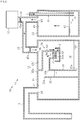
Fig. 1 is a schematic sectional view illustrating a suction discharge device of a first embodiment. -
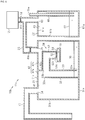
Fig. 2 is a schematic sectional view illustrating operation of the suction discharge device of the first embodiment. -
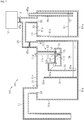
Fig. 3 is a schematic sectional view illustrating operation of the suction discharge device of the first embodiment. - [
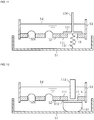
Fig. 4 ] Parts (a) to (f) ofFig. 4 are schematic sectional views illustrating operation of a negative pressure control unit of the first embodiment. -
Fig. 5 is a schematic sectional view illustrating a modification of the suction discharge device of the first embodiment. -
Fig. 6 is a schematic sectional view illustrating a modification of the suction discharge device of the first embodiment. -
Fig. 7 is a schematic sectional view illustrating a suction discharge device of a second embodiment. - [
Fig. 8 ] Parts (a) to (d) ofFig. 8 are schematic sectional views illustrating operation of a negative pressure control unit of the second embodiment. -
Fig. 9 is a schematic sectional view illustrating a modification of the negative pressure control unit of the second embodiment. -
Fig. 10 is a schematic sectional view illustrating a modification of the negative pressure control unit of the second embodiment. -
Fig. 11 is a schematic sectional view illustrating a modification of the negative pressure control unit of the second embodiment. -
Fig. 12 is a schematic sectional view illustrating a modification of the negative pressure control unit of the second embodiment. - Hereafter, embodiments will be described. In the accompanying drawings, constitute elements may be illustrated in an enlarged manner to facilitate ease of understanding. Dimensional ratios of the constituent elements may differ from the actual ratios or may differ from the ratios in other drawings. Furthermore, in the sectional views, the hatching of some constituent elements may be omitted to facilitate ease of understanding.
- Hereafter, a first embodiment will be described. As illustrated in
Fig. 1 , asuction discharge device 10 includes asuction discharge unit 11 and asuction pump 12 functioning as a suction source. - The
suction discharge unit 11 is connected to a subject via aconnection tube 13. For example, the leading end of theconnection tube 13 is inserted into the inside of the chest cavity of a patient who is the subject. Furthermore, thesuction discharge unit 11 is connected to thesuction pump 12 via theconnection pipe 25. Thesuction pump 12 generates a negative pressure inside thesuction discharge unit 11. - The
suction discharge unit 11 includes afirst unit 21 and asecond unit 22. Thefirst unit 21 and thesecond unit 22 are connected to each other by aconnection pipe 25. In this embodiment, thesuction pump 12 is connected to theconnection pipe 25 via aconnection pipe 14. Thus, thesuction pump 12 is connected to thefirst unit 21 and thesecond unit 22. - The
first unit 21 is, for example, formed in a box-like shape and includes a bottom plate part 31a, aside wall part 31b, and atop part 31c. In this embodiment, theside wall part 31b is formed in a cylindrical shape, and the bottom plate part 31a closes the lower end of the cylindricalside wall part 31b and thetop part 31c closes the upper end of the cylindricalside wall part 31b. A transparent material such as a transparent plastic is used as the material of thefirst unit 21 such that the inside of thefirst unit 21 can be observed from the outside. - The internal space of the
first unit 21 is divided into astorage chamber 41 and awater sealing chamber 42 by afirst partition wall 32. Thefirst partition wall 32 is connected to the bottom plate part 31a and theside wall part 31b and anupper end 32a of thefirst partition wall 32 is spaced apart from thetop part 31c. Therefore, thestorage chamber 41 and thewater sealing chamber 42 communicate with each other in the upper part of thefirst unit 21 and a gas is able to move between thestorage chamber 41 and thewater sealing chamber 42. - In the
storage chamber 41, afirst connection hole 34 that allows communication between thestorage chamber 41 and the space outside the unit is formed in thetop part 31c. Theconnection tube 13 is connected to thefirst connection hole 34. For example, theconnection tube 13 is connected to a connection pipe (not illustrated) formed in the upper surface of thefirst unit 21. Thefirst connection hole 34 allows communication between the inside of thestorage chamber 41 and the inside of theconnection tube 13, in other words, the chest cavity of the subject. - The
water sealing chamber 42 is divided into afirst chamber 42a and asecond chamber 42b by asecond partition wall 33. Thesecond partition wall 33 is connected to thetop part 31c and theside wall part 31b and alower end 33a of thesecond partition wall 33 is spaced apart from the bottom plate part 31a. Therefore, thefirst chamber 42a and thesecond chamber 42b communicate with each other in a lower part of thefirst unit 21. - In other words, the internal space of the
first unit 21 is divided into thestorage chamber 41 and thewater sealing chamber 42 by thefirst partition wall 32. Thewater sealing chamber 42 is divided into thefirst chamber 42a and thesecond chamber 42b by thesecond partition wall 33. - In the
second chamber 42b, asecond connection hole 35 that allows communication between thesecond chamber 42b and the space outside the unit is formed in thetop part 31c. Theconnection pipe 25 is connected to thesecond connection hole 35. For example, theconnection pipe 25 is connected to a connection pipe (not illustrated) formed in the upper surface of thefirst unit 21. Thesecond connection hole 35 allows communication between the inside of thesecond chamber 42b and the inside of theconnection pipe 25. - A
filter 45a is disposed in theconnection pipe 14. Thefilter 45a is a hydrophobic filter. Thefilter 45a allows a gas to pass therethrough and does not allow a liquid to pass therethrough. Therefore, thefilter 45a prevents a liquid from entering thesuction pump 12, which functions as a suction source. - A
filter 45b is disposed in theconnection pipe 25. Thefilter 45b is a bacteria filter that does not allow bacteria and the like to pass therethrough. Thefilter 45b is provided in order to prevent entry of bacteria into theconnection tube 13 from the outside air. Therefore, it is sufficient that thefilter 45b be provided closer to the outside air than theconnection tube 13, and in this embodiment, thefilter 45b is disposed in theconnection pipe 25. - Sealing
water 36, serving as a water sealing part, is accommodated in thewater sealing chamber 42. The sealingwater 36 is sterile water. In addition, the sealingwater 36 may be colored. The sealingwater 36 is stored in thewater sealing chamber 42 such that the water surface in thefirst chamber 42a and the water surface in thesecond chamber 42b are higher than thelower end 33a of thesecond partition wall 33 in a state where thesuction pump 12 is not operating. - The
first unit 21 has a negativepressure control unit 50. In this embodiment, the negativepressure control unit 50 is accommodated in thesecond chamber 42b of thewater sealing chamber 42. - The negative
pressure control unit 50 includes aliquid retaining part 51, acontrol member 52, and asupport tube 53. - The
liquid retaining part 51 is disposed at a prescribed position using a support member, which is not illustrated. For example, theliquid retaining part 51 is fixed to thesupport tube 53, which will be described later, via the support member, which is not illustrated. In addition to being fixed to thesupport tube 53, theliquid retaining part 51 may be fixed in place using an inner wall of thesecond chamber 42b via a support member. Theliquid retaining part 51 is formed so as to be able to retain a liquid 54. The liquid 54 is sterile water similarly to the sealingwater 36 described above. The liquid 54 may be colored. The pressure inside thesecond chamber 42b acts on the liquid 54. The liquid 54 retained in theliquid retaining part 51 is supplied at the same time as the sealingwater 36 in thewater sealing chamber 42, for example. For example, the liquid 54 is supplied to theliquid retaining part 51. The liquid 54 that overflows from theliquid retaining part 51 is retained in thewater sealing chamber 42 as the sealingwater 36. - The
control member 52 is formed to have a plate-like shape. Thecontrol member 52 includescontrol holes 52X that penetrate through thecontrol member 52 in the thickness direction (up-down direction in figure). The control holes 52X are formed so as to have a prescribed shape. The control holes 52X are formed in a polygonal shape such as a triangular shape or one with a greater number of sides, or a circular shape or an elliptical shape, for example. - The
control member 52 is suitably formed in order to control the surface tension of the liquid 54 described above. The thickness of thecontrol member 52 may be 20 µm, for example. For example, in the case of a circular shape, the size of thecontrol holes 52X can be 10-100 µm. - The
control member 52 is fixed in place inside thesupport tube 53. Thecontrol member 52 is supported so as to contact the liquid 54 retained in theliquid retaining part 51. For example, thecontrol member 52 is fixed to aleading end 53a of thesupport tube 53 and theleading end 53a of thesupport tube 53 is disposed inside theliquid retaining part 51. More specifically, theleading end 53a of thesupport tube 53 is disposed inside the liquid 54 retained in theliquid retaining part 51. - A
base end 53b of thesupport tube 53 is connected to thesecond partition wall 33. Anopening 33b is formed in thesecond partition wall 33 and the inside of thefirst chamber 42a and the inside of thesupport tube 53 communicate with each other via theopening 33b. In other words, by using thesupport tube 53, thecontrol member 52 is disposed between thefirst chamber 42a and thesecond chamber 42b and the liquid 54 retained in theliquid retaining part 51 is disposed in thesecond chamber 42b. - The inner space of the
second unit 22 functions as apressure adjusting chamber 43 that adjusts the pressure (negative pressure) inside thefirst unit 21. - The
second unit 22 is, for example, formed in a box-like shape and includes abottom plate part 61a, aside wall part 61b, and atop part 61c. In this embodiment, theside wall part 61b is formed in a cylindrical shape, and thebottom plate part 61a closes the lower end of the cylindricalside wall part 61b and thetop part 61c closes the upper end of the cylindricalside wall part 61b. A transparent material such as a transparent plastic is used as the material of thesecond unit 22 such that the inside of thesecond unit 22 can be observed from the outside. - A
third connection hole 63 that allows communication between the inside of thesecond unit 22 and the outside is formed in thetop part 61c of thesecond unit 22. Theconnection pipe 25 is connected to thethird connection hole 63. For example, theconnection pipe 25 is connected to a connection pipe (not illustrated) formed in the upper surface of thesecond unit 22. Thethird connection hole 63 allows communication between the inside of thesecond unit 22 and the inside of theconnection pipe 25. This connection pipe allows communication between the inside of thesecond unit 22 and the water sealing chamber 42 (second chamber 42b) of thefirst unit 21. - The
second unit 22 includes athin pipe 65. In this embodiment, the upper end of thethin pipe 65 protrudes upward from thetop part 61c and the inside of thethin pipe 65 is open to the atmosphere via anopening 65a in the upper end of thethin pipe 65. The lower end of thethin pipe 65 is positioned in the vicinity of thebottom plate part 61a. Thesecond unit 22 controls the pressure acting in thesecond chamber 42b of thewater sealing chamber 42 via the depth ofsterile water 67. - Next, operation of the above-described
suction discharge device 10 will be described. - When the inside of the
second unit 22 is made to have a negative pressure by thesuction pump 12, the inside of thesecond unit 22 is maintained at a negative pressure corresponding to the height of the water surface of thesterile water 67. The inner space of thesecond unit 22 communicates with the inside of thefirst unit 21 and thesecond chamber 42b of thewater sealing chamber 42 via theconnection pipe 25. Therefore, the second unit 22 (pressure adjusting chamber 43) adjusts the pressure inside thefirst unit 21. For example, the second unit 22 (pressure adjusting chamber 43) adjusts the pressure of thesecond chamber 42b to a prescribed pressure (for example, -10 hPa from the atmospheric pressure). - In the
first unit 21, the water level of the sealingwater 36 in thesecond chamber 42b rises due to the negative pressure of thesecond chamber 42b and the water level of the sealingwater 36 in thefirst chamber 42a falls. Thus, thestorage chamber 41 comes to have a prescribed negative pressure (for example, -8 hPa from the atmospheric pressure). The negative pressure of thestorage chamber 41 is maintained by thesuction pump 12 and thepressure adjusting chamber 43, and a suction force is applied to the chest cavity of the subject via theconnection tube 13. Discharge liquid and gas such as air is guided from the chest cavity of the subject to thestorage chamber 41 via theconnection tube 13 and the discharge liquid is stored in thestorage chamber 41. The gas passes under thelower end 33a of thesecond partition wall 33 from thefirst chamber 42a of thewater sealing chamber 42, which communicates with thestorage chamber 41, becomes air bubbles inside the sealingwater 36, and reaches thesecond chamber 42b. - The negative pressure inside the
storage chamber 41 may become excessive (for example, -40 hPa from the atmospheric pressure) as a result of the subject coughing or the like. - As illustrated in
Fig. 2 , the water level of the sealingwater 36 in thefirst chamber 42a rises and the water level in thesecond chamber 42b falls due to the negative pressure inside thestorage chamber 41. At this time, the liquid 54 in theliquid retaining part 51 of the negativepressure control unit 50 flows into thesupport tube 53 via thecontrol member 52 due to the pressure difference between the pressure of the storage chamber 41 (first chamber 42a) and the pressure of thesecond chamber 42b. In addition, gas inside thesecond chamber 42b flows into the inside of thesupport tube 53 via the control holes 52X of thecontrol member 52, turns into thebubbles 71, and passes through the liquid 54. In other words, the negativepressure control unit 50 causes the gas inside thesecond chamber 42b to flow into thefirst chamber 42a (storage chamber 41) due to the pressure of thefirst chamber 42a (storage chamber 41) and the pressure of thesecond chamber 42b. Thus, the pressure inside thestorage chamber 41 rises and the excessive negative pressure is relieved by the gas being supplied to thestorage chamber 41 from thesecond chamber 42b via thefirst chamber 42a. - As illustrated in
Fig. 3 , when the pressure inside thestorage chamber 41 falls from the excessive negative pressure, the water level of the sealingwater 36 in thefirst chamber 42a, which communicates with thestorage chamber 41, falls in accordance with this pressure. At this time, in addition to the pressure of thefirst chamber 42a acting on the liquid 54 inside thesupport tube 53 via thesupport tube 53, the pressure of thesecond chamber 42b also acts on the liquid 54 insidesupport tube 53 via the control holes 52X. When the pressure difference between thefirst chamber 42a and thesecond chamber 42b reaches a prescribed value as a result of balance being established between the surface tension of the liquid 54 at the control holes 52X, the pressure of thefirst chamber 42a, and the pressure of thesecond chamber 42b, a state is reached in which the gas stops flowing into the first chamber and in which the liquid 54 is retained inside thesupport tube 53. It is confirmed from the thus-retained liquid 54 that an excessive negative pressure was generated in thestorage chamber 41. - Operation of the negative
pressure control unit 50 will be described in detail. - As illustrated in part (a) of
Fig. 4 , the liquid 54 is retained in theliquid retaining part 51 in an initial state (state where the negative pressure ofstorage chamber 41 is appropriate as illustrated inFig. 1 ). - When the negative pressure of the
storage chamber 41 becomes excessive as illustrated inFig. 2 , the liquid 54 in theliquid retaining part 51 flows into the inside of thesupport tube 53 via the control holes 52X of thecontrol member 52 due to the negative pressure of thefirst chamber 42a, which communicates with thestorage chamber 41, as illustrated in part (b) ofFig. 4 . In addition, gas inside thesecond chamber 42b advances into the inside of thesupport tube 53 from the control holes 52X as illustrated in parts (c) and (d) ofFig. 4 . Then, the gas turns into thebubbles 71 and passes through the liquid 54, as illustrated in part (e) ofFig. 4 . - As illustrated in
Fig. 3 , when the value of the sum of the pressure of thefirst chamber 42a, the liquid pressure generated by the weight of the liquid 54 retained inside thesupport tube 53, and the surface tension at the surface of the liquid 54 generated by thecontrol holes 52X is equal to the pressure of thesecond chamber 42b, the flow of gas from thesecond chamber 42b into thefirst chamber 42a stops. At this time, a state arises in which the liquid 54 is retained inside thesupport tube 53 due to the balance between the pressure of thestorage chamber 41 and thefirst chamber 42a, the surface tension generated in the liquid 54 by the control holes 52X, and the pressure of thesecond chamber 42b. - The control holes 52X have a circular shape in this embodiment. R represents the diameter of the control holes 52X. ρ represents the density of the liquid 54, σ represents the surface tension coefficient of the liquid 54, h represents the height of the liquid 54 retained in the
support tube 53, and g represents the acceleration due to gravity. When P1 represents the pressure of thefirst chamber 42a and P2 represents the pressure of thesecond chamber 42b,
Fig. 4 . Therefore, the pressure of thestorage chamber 41, which communicates with thefirst chamber 42a, can be controlled to a pressure according to the diameter R of thecontrol holes 52X and the density ρ, height h, and surface tension coefficient σ of the liquid 54. - As described above, according to this embodiment, the following effects are realized.
- (1-1) The
suction discharge device 10 includes thesuction discharge unit 11 and thesuction pump 12. Thesuction discharge unit 11 includes thefirst unit 21 and thesecond unit 22. Thesecond unit 22 controls the pressure inside thefirst unit 21. Thefirst unit 21 includes thestorage chamber 41 and thewater sealing chamber 42. Thewater sealing chamber 42 includes thefirst chamber 42a, which communicates with thestorage chamber 41, and thesecond chamber 42b, which is sealed from thefirst chamber 42a by the sealingwater 36. - The negative
pressure control unit 50 is disposed in thesecond chamber 42b. The negativepressure control unit 50 includes the liquid retaining part that retains the liquid 54, thecontrol member 52 that includes the control holes 52X, and thesupport tube 53 that supports thecontrol member 52. - When the negative pressure of the
storage chamber 41 becomes excessive, the liquid 54 flows into the inside of thesupport tube 53 via the control holes 52X of thecontrol member 52 due to the pressure difference between thefirst chamber 42a, which communicates with thestorage chamber 41, and thesecond chamber 42b. In addition to the pressure of thefirst chamber 42a acting on the liquid 54 inside thesupport tube 53 via thesupport tube 53, the pressure of thesecond chamber 42b also acts on the liquid 54 insidesupport tube 53 via the control holes 52X. Therefore, gas in thesecond chamber 42b flows into the inside of thesupport tube 53 via the control holes 52X, turns into thebubbles 71, and passes through the liquid 54 due to the pressure difference between thefirst chamber 42a and thesecond chamber 42b. That is, gas in thesecond chamber 42b flows into thefirst chamber 42a via the negativepressure control unit 50. The negative pressure of thefirst chamber 42a, that is, the negative pressure of thestorage chamber 41 can be reduced by this inflow of gas. Thus, it is possible to automatically prevent the negative pressure of thestorage chamber 41 and thefirst chamber 42a from becoming excessively large. - When the pressure difference between the
first chamber 42a and thesecond chamber 42b reaches a prescribed value as a result of balance being established between the surface tension of the liquid 54 at the control holes 52X, the pressure of thefirst chamber 42a, and the pressure of thesecond chamber 42b, a state is reached in which the gas stops flowing into thefirst chamber 42a and in which the liquid 54 is retained inside thesupport tube 53. It can be confirmed from the thus-retained liquid 54 that an excessive negative pressure was generated in thestorage chamber 41. - (1-2) The negative
pressure control unit 50 stops the flow of gas from thesecond chamber 42b to thefirst chamber 42a when the value of the sum of the pressure of thefirst chamber 42a, the liquid pressure generated by the weight of the liquid 54 contained inside thesupport tube 53, and the surface tension of the liquid 54 becomes equal to the pressure of thesecond chamber 42b. Therefore, once the excessive negative pressure has been released, the pressure of thestorage chamber 41, which communicates with thefirst chamber 42a, can be controlled to a pressure corresponding to the liquid pressure generated by the weight of the liquid 54 and the pressure of thesecond chamber 42b. - (1-3) In this embodiment, the negative
pressure control unit 50 is disposed in thesecond chamber 42b. Therefore, since there is no need to connect a pipeline or the like to the outside in order to allow gas in thesecond chamber 42b to flow from thesecond chamber 42b to thefirst chamber 42a via the negativepressure control unit 50, an increase in the size of thesuction discharge unit 11 can be suppressed. - The first embodiment may be implemented in the following ways.
- In the above-described embodiment, the negative
pressure control unit 50 is disposed inside the water sealing chamber 42 (second chamber 42b) of thefirst unit 21, but the negativepressure control unit 50 may instead be disposed outside thefirst unit 21. - As illustrated in
Fig. 5 , asuction discharge unit 11a of asuction discharge device 10a includes thefirst unit 21, thesecond unit 22, and athird unit 23. Thefirst unit 21 includes thestorage chamber 41 and thewater sealing chamber 42 and thewater sealing chamber 42 includes thefirst chamber 42a and thesecond chamber 42b. Thesecond unit 22 communicates with thefirst unit 21, and thesecond unit 22 is connected to thesuction pump 12 and adjusts the pressure of thefirst unit 21. - The
third unit 23 is, for example, formed in a box-like shape and includes abottom plate part 81a, aside wall part 81b, and a top part 81c. A transparent material such as a transparent plastic is used as the material of thethird unit 23 such that the inside of thethird unit 23 can be observed from the outside. - The liquid 54 is retained in the
third unit 23. A cap, which is not illustrated, is provided in a top part of thethird unit 23 and the liquid 54 is made to be retained inside thethird unit 23 by opening and closing the cap. Thesupport tube 53 is inserted into the inside of thethird unit 23 from the top part 81c of thethird unit 23, and thecontrol member 52 is attached to the inside of thesupport tube 53. In other words,third unit 23 constitutes a negative pressure control unit. - The
support tube 53 communicates with thefirst chamber 42a via aconnection pipe 26 between thethird unit 23 and thefirst unit 21. The inside of thethird unit 23 communicates with thesecond chamber 42b via aconnection pipe 27 and theconnection pipe 25. The pressure of thesecond chamber 42b acts on the liquid 54 retained in theliquid retaining part 51 via theconnection pipe 27 and theconnection pipe 25. Thefilter 45b is disposed in theconnection pipe 26 in thesuction discharge unit 11a. - Similarly to the
suction discharge device 10 of the above-described embodiment, thesuction discharge device 10a can suppress an excessive negative pressure in thestorage chamber 41 and thefirst chamber 42a. Furthermore, it can be confirmed from the state of the liquid 54 in thethird unit 23 that an excessive negative pressure was generated. - In addition, an increase in the size of the
suction discharge device 10a can be suppressed by thethird unit 23. For example, it is thought that an excessive negative pressure in thestorage chamber 41 and thefirst chamber 42a is suppressed by a unit having a thin pipe such as thesecond unit 22. However, with a unit having a thin pipe, there is an increase in unit size in order to set the pressure and an increase in the size of the suction discharge unit is incurred. In contrast, in thethird unit 23 described above, the thickness of thecontrol member 52, which functions as a valve for controlling gas flow, is for example 20 µm as described above. Therefore, thethird unit 23 is smaller in size than a unit that uses a thin pipe. Therefore, an increase in size can be suppressed in thesuction discharge device 10a in which thethird unit 23 is connected to the outside of thefirst unit 21. - The shape of the negative
pressure control unit 50 of the above-described embodiment may be changed as appropriate. - As illustrated in
Fig. 6 , the liquid 54 is retained in theliquid retaining part 51 of the negativepressure control unit 50 in asuction discharge unit 11b of asuction discharge device 10b. Thecontrol member 52 is attached to an end portion of thesupport tube 53 and is supported so as to contact the liquid 54 retained in theliquid retaining part 51. The same operations and effects as in the above-described embodiment can also be obtained in the case where thecontrol member 52 is supported in this way. - Hereafter, a second embodiment will be described.
- In this embodiment, constituent members that are identical to those in the above-described embodiment will be denoted by identical symbols and the description of such members will be partially or entirely omitted.
- As illustrated in
Fig. 7 , asuction discharge device 100 includes asuction discharge unit 101 and thesuction pump 12 functioning as a suction source. - The
suction discharge unit 101 is connected to a subject via theconnection tube 13. For example, the leading end of theconnection tube 13 is inserted into the inside of the chest cavity of a patient who is the subject. Furthermore, thesuction discharge unit 101 is connected to thesuction pump 12 via theconnection pipe 25. Thesuction pump 12 generates a negative pressure inside thesuction discharge unit 101. - The
suction discharge unit 101 includes thefirst unit 21 and thesecond unit 22. - The
first unit 21 has a negativepressure control unit 110. In this embodiment, the negativepressure control unit 110 is accommodated in thesecond chamber 42b of thewater sealing chamber 42. - The negative
pressure control unit 110 includes theliquid retaining part 51, thecontrol member 52, thesupport tube 53, a fixedmember 111, avalve body 112, an urgingmember 113, and aseal releasing member 114. - The fixed
member 111 is formed to have a plate-like shape. The fixedmember 111 has aliquid passage hole 111X that penetrates through the fixedmember 111 in the thickness direction (up-down direction in figure). Theliquid passage hole 111X is formed in a prescribed shape. - In this embodiment, the fixed
member 111 is disposed at aleading end 53a of thesupport tube 53. In addition, the fixedmember 111 is disposed parallel to thecontrol member 52. The fixedmember 111 is disposed such that theliquid passage hole 111X of the fixedmember 111 is at a prescribed position with respect to thecontrol member 52. For example, the fixedmember 111 is disposed such that theliquid passage hole 111X of the fixedmember 111 is positioned at the same height as the control holes 52X of the control member 52 (upper edge ofliquid passage hole 111X and upper edges ofcontrol holes 52X are at the same height). In other words, the fixedmember 111 is disposed such that the upper surface of the fixedmember 111 and the upper surface of thecontrol member 52 are positioned at the same height. - In addition, the fixed
member 111 may be disposed such that theliquid passage hole 111X of the fixedmember 111 is positioned at a lower height than the control holes 52X of thecontrol member 52. In other words, the fixedmember 111 may be disposed such that the upper surface of the fixedmember 111 is positioned at a lower height than the upper surface of thecontrol member 52. - The
valve body 112 is disposed on the lower surface side of the fixedmember 111. Thevalve body 112 is formed so as to be larger than theliquid passage hole 111X of the fixedmember 111 and is formed so as to have a size so as to contact the lower surface of the fixedmember 111 along the entire periphery of theliquid passage hole 111X in a plan view. Thevalve body 112 seals theliquid passage hole 111X of the fixedmember 111 in a state where thevalve body 112 contacts the lower surface of the fixedmember 111. When thevalve body 112 is separated from the fixedmember 111, theliquid passage hole 111X of the fixedmember 111 enters an open state. In other words, thevalve body 112 is able to switch theliquid passage hole 111X of the fixedmember 111 between a sealed state and an open state. - The urging
member 113 is disposed between the lower surface of thevalve body 112 and theliquid retaining part 51. The urgingmember 113 has elasticity and urges thevalve body 112 in a direction so as to close theliquid passage hole 111X of the fixedmember 111. For example, a compression spring can be used as the urgingmember 113. - The
seal releasing member 114 is disposed above thevalve body 112. Theseal releasing member 114 is formed in a rod-like shape that extends in an up-down direction. In this embodiment, a lower end of theseal releasing member 114 is disposed on the upper surface of thevalve body 112 and an upper end of theseal releasing member 114 protrudes to outside thefirst unit 21 from aninsertion hole 31d formed in atop part 31c of thefirst unit 21. In this embodiment, theseal releasing member 114 is formed so as to be integrated with thevalve body 112. When theseal releasing member 114 is pushed down against the urging force of the urgingmember 113, thevalve body 112 is separated from the fixedmember 111 and theliquid passage hole 111X of the fixedmember 111 enters an open state. - Next, operation of the above-described
suction discharge device 100 will be described. - Similarly to the
suction discharge device 10 of the first embodiment, the internal pressure of thesecond chamber 42b of thefirst unit 21 is adjusted to a prescribed pressure (for example, -10 hPa from atmospheric pressure) using thesuction pump 12. Thus, thestorage chamber 41 of thefirst unit 21 is made to be at a desired negative pressure (for example, -8 hPa from atmospheric pressure). - The negative pressure inside the
storage chamber 41 may become excessive (for example, -40 hPa from the atmospheric pressure) as a result of the subject coughing or the like. In this case, the liquid 54 in theliquid retaining part 51 flows into thesupport tube 53 via thecontrol member 52 due to the pressure difference between the pressure of the storage chamber 41 (first chamber 42a) and the pressure of thesecond chamber 42b. In addition, gas inside thesecond chamber 42b flows into the inside of thesupport tube 53 via the control holes 52X of thecontrol member 52, turns into thebubbles 71, and passes through the liquid 54. In other words, the negativepressure control unit 110 causes the gas inside thesecond chamber 42b to flow into thefirst chamber 42a (storage chamber 41) due to the pressure of thefirst chamber 42a (storage chamber 41) and the pressure of thesecond chamber 42b. Thus, the pressure inside thestorage chamber 41 rises and the excessive negative pressure is relieved by the gas being supplied to thestorage chamber 41 from thesecond chamber 42b via thefirst chamber 42a. - When the pressure inside the
storage chamber 41 falls from the excessive negative pressure, the water level of the sealingwater 36 in thefirst chamber 42a, which communicates with thestorage chamber 41, falls in accordance with this pressure. When the pressure difference between thefirst chamber 42a and thesecond chamber 42b reaches a prescribed value as a result of balance being established between the surface tension of the liquid 54 at the control holes 52X, the pressure of thefirst chamber 42a, and the pressure of thesecond chamber 42b, a state is reached in which the gas stops flowing into the first chamber and in which the liquid 54 is retained inside thesupport tube 53. It is confirmed from the thus-retained liquid 54 that an excessive negative pressure was generated in thestorage chamber 41. - Part (a) of
Fig. 8 illustrates a state in which the pressure inside the storage chamber 41 (refer toFig. 7 ) has fallen from the excessive negative pressure due to the negativepressure control unit 110. The liquid 54 is retained on the upper side of thecontrol member 52, that is, on thefirst chamber 42a side (storage chamber 41 side) of thecontrol member 52. As illustrated in part (b) ofFig. 8 , when a medical professional manually pushes theseal releasing member 114 down, thevalve body 112 is pushed downward by theseal releasing member 114 and theliquid passage hole 111X of the fixedmember 111 enters an open state. Thus, the retained liquid 54 flows into theliquid retaining part 51 via theliquid passage hole 111X. - Since the
liquid passage hole 111X of the fixedmember 111 is positioned at the same height as the control holes 52X of thecontrol member 52, the liquid 54 disappears from the upper surface side of thecontrol member 52, as illustrated in part (c) ofFig. 8 . Then, as illustrated in part (d) ofFig. 8 , when the medical professional releases his/her hand from theseal releasing member 114, thevalve body 112 is made to closely contact the lower surface of the fixedmember 111 by the urgingmember 113. Thus, theliquid passage hole 111X of the fixedmember 111 is put into a sealed state by thevalve body 112. - In other words, the negative
pressure control unit 110 is reset, i.e., returned to its initial state by thevalve body 112, the fixedmember 111, the urgingmember 113, and theseal releasing member 114. - Then, when an excessive negative pressure is once again generated in the
storage chamber 41, the liquid 54 in theliquid retaining part 51 moves into the inside of thesupport tube 53 via the control holes 52X of thecontrol member 52 and is retained inside thesupport tube 53. It can be confirmed from the thus-retained liquid 54 that an excessive negative pressure was generated. Then, once the confirmation has been made, thevalve body 112 is pushed down by operating theseal releasing member 114 so as to put theliquid passage hole 111X of the fixedmember 111 into an open state, the retained liquid 54 is allowed to flow out into theliquid retaining part 51, and the negativepressure control unit 110 is reset. Thus, by resetting the negativepressure control unit 110 after confirming the generation of an excessive negative pressure, it is possible to confirm the generation of an excessive negative pressure after this confirmation. - As described above, according to this embodiment, the following effects are realized in addition to the effects of the first embodiment.
- (2-1) The negative
pressure control unit 110 includes the liquid retaining part that retains the liquid 54, thecontrol member 52 that includes the control holes 52X, and thesupport tube 53 that supports thecontrol member 52. In addition, the negativepressure control unit 110 further includes the fixedmember 111 including theliquid passage hole 111X, thevalve body 112 that is able to switch theliquid passage hole 111X of the fixedmember 111 between a sealed state and an open state, and an urgingmember 113 that urges thevalve body 112 in a direction so as to seal theliquid passage hole 111X.
Theliquid passage hole 111X of the fixedmember 111 is put into an open state by thevalve body 112 and as a result the liquid 54 retained in thesupport tube 53 flows into theliquid retaining part 51 via theliquid passage hole 111X and the negativepressure control unit 110 is reset to the initial state. In the case where an excessive negative pressure is generated in thestorage chamber 41 once again, the liquid 54 is retained in thesupport tube 53, and therefore it is possible to confirm that an excessive negative pressure has been generated once again in thestorage chamber 41 from this retained liquid 54. - (2-2) The negative
pressure control unit 110 includes theseal releasing member 114 that releases the sealing state of theliquid passage hole 111X of the fixedmember 111 using thevalve body 112, that is, puts theliquid passage hole 111X into an open state. When theliquid passage hole 111X is put into an open state, the liquid 54 retained inside thesupport tube 53, that is, retained on thefirst chamber 42a (storage chamber 41) side of thecontrol member 52 is allowed to flow into theliquid retaining part 51, and thus, the negativepressure control unit 110 can be easily reset to the initial state. - The second embodiment may be implemented in the following ways.
- The various members included in the negative
pressure control unit 110 of this embodiment may be changed as appropriate. - As illustrated in
Fig. 9 , theseal releasing member 114 and thevalve body 112 may be provided as separate members. - As illustrated in
Fig. 10 , avalve body 121 is disposed on the upper surface side of the fixedmember 111. An urgingmember 122 is disposed above the fixedmember 111 and between asupport member 123, which is fixed to thesupport tube 53, and thevalve body 121, and the urgingmember 122 urges thevalve body 121 in a direction so as to seal theliquid passage hole 111X of the fixedmember 111, i.e., toward the fixedmember 111. For example, a compression spring can be used as the urgingmember 122. Aseal releasing member 124 is fixed to the upper surface of thevalve body 121. InFig. 10 , thevalve body 121 and theseal releasing member 124 are illustrated as being integrated with each other. When theseal releasing member 124 is pulled upward and thevalve body 121 is separated from the fixedmember 111, the liquid 54 retained on thefirst chamber 42a side of the control member 52 (refer toFig. 7 ) flows into theliquid retaining part 51 from theliquid passage hole 111X of the fixedmember 111. In this case, theseal releasing member 124 functions as a separating member that separates thevalve body 121 from the fixedmember 111. - In addition, the
seal releasing member 124 and thevalve body 121 may be provided as separate members. Theseal releasing member 124 and thevalve body 121 may be provided so as to be integrated with each other by integrating the lower end of theseal releasing member 124 with an insertion hole formed in thevalve body 121 using press fitting, an adhesive, or the like. Furthermore, theseal releasing member 124 and thevalve body 121 may be integrated with each other by forming a male screw thread on the lower end of the seal releasing member and forming a female screw thread in an insertion hole in thevalve body 121 and then screwing these threads together. - As illustrated in
Fig. 11 , thevalve body 121 is disposed on the upper surface side of the fixedmember 111. An urgingmember 131 is disposed between the lower surface of thevalve body 121 and theliquid retaining part 51 and urges thevalve body 121 in a direction so as to seal theliquid passage hole 111X of the fixedmember 111, that is, toward the upper surface of the fixedmember 111. For example, a pull spring can be used the urgingmember 131. Aseal releasing member 124 is fixed to the upper surface of thevalve body 121. InFig. 11 , thevalve body 121 and theseal releasing member 124 are illustrated as being integrated with each other. When theseal releasing member 124 is pulled upward and thevalve body 121 is separated from the fixedmember 111, the liquid 54 retained on thefirst chamber 42a side of the control member 52 (refer toFig. 7 ) flows into theliquid retaining part 51 from theliquid passage hole 111X of the fixedmember 111. In this case, theseal releasing member 124 functions as a separating member that separates thevalve body 121 from the fixedmember 111. - As illustrated in
Fig. 12 , thevalve body 112 is disposed on the lower surface side of the fixedmember 111. An urgingmember 141 is disposed between the lower surface of thevalve body 112 and theliquid retaining part 51 and the urgingmember 141 urges thevalve body 112 in a direction so as to seal theliquid passage hole 111X of the fixedmember 111, that is, toward the upper surface of the fixedmember 111. A material having elasticity such as rubber can be used for the urgingmember 141 and the urgingmember 141 is fixed to the lower surface of thevalve body 112. A hollow member such as a balloon can also be used as the urging member. Thevalve body 112 and theseal releasing member 114 are illustrated as being separate members inFig. 12 , but thevalve body 112 and theseal releasing member 114 may instead be integrated with each other. - The above embodiments may be implemented in the following ways.
- In the above-described embodiments, the
suction discharge unit 11 that includes thefirst unit 21 and thesecond unit 22 is described, but a suction discharge unit in which thefirst unit 21 and thesecond unit 22 are integrated with each other may instead be adopted. - In the above-described embodiments, a pump that allows pressure setting may be used as the
suction pump 12 and thesecond unit 22 may be omitted. - In the above-described embodiments, the
storage chamber 41 and thewater sealing chamber 42 may be formed as separate containers (units) and may be connected to each other such that thefirst chamber 42a of thewater sealing chamber 42 and thestorage chamber 41 communicate with each other. Furthermore, thefirst chamber 42a and thesecond chamber 42b of thewater sealing chamber 42 may be formed as separate containers and may be connected to each other so as to be isolated from each other by the sealingwater 36 functioning as a water sealing part. -
- 10
- suction discharge device,
- 11
- suction discharge unit,
- 12
- suction pump (suction source),
- 34
- first connection hole,
- 35
- second connection hole,
- 32
- first partition wall,
- 33
- second partition wall,
- 41
- storage chamber,
- 42
- water sealing chamber,
- 42a
- first chamber,
- 42b
- second chamber,
- 43
- sealing water (water sealing part),
- 50
- negative pressure control unit,
- 51
- liquid retaining part,
- 52
- control member,
- 52X
- control hole,
- 53
- support tube,
- 54
- liquid,
- 100
- suction discharge device,
- 101
- suction discharge unit,
- 110
- negative pressure control unit,
- 111
- fixed member,
- 111X
- liquid passage hole,
- 112
- valve body,
- 113
- urging member,
- 114
- seal releasing member.
Claims (14)
- A suction discharge unit disposed between a subject and a suction source, comprising:a first connection hole that communicates with the subject;a second connection hole that communicates with the suction source;a storage chamber that stores a first liquid that flows thereinto from the first connection hole;a water sealing chamber including a first chamber that communicates with the storage chamber and into which passage of the first liquid is prevented by a first partition wall and a second chamber that is isolated from the first chamber by a water sealing part and a second partition wall and that is connected to the suction source via the second connection hole; anda negative pressure control unit that controls a pressure of the first chamber by causing gas to flow from the second chamber to the first chamber on the basis of a pressure of the second chamber and the pressure of the first chamber;wherein the negative pressure control unit includes a liquid retaining part that is able to retain a second liquid and that is disposed such that the pressure of the second chamber acts on the second liquid, anda control member that has a control hole for controlling inflow of the gas on the basis of surface tension of the second liquid.
- The suction discharge unit according to Claim 1,
wherein the negative pressure control unit includes a support tube that has a first end portion, the entire edge of the control member being attached to an inner periphery of the first end portion, and a second end portion that is open to the first chamber, the first end portion being disposed in the liquid retaining part, and
the negative pressure control unit stops the gas from flowing from the second chamber to the first chamber when the value of a sum of the pressure of the first chamber, a liquid pressure generated by the weight of the second liquid contained inside the support tube, and a surface tension of the second liquid is equal to the pressure of the second chamber. - The suction discharge unit according to Claim 2,
wherein the control hole has a circular shape, and
the flow of the gas from the second chamber to the first chamber stops when
where P1 is the pressure of the first chamber, P2 is the pressure of the second chamber, ρ is the density of the second liquid, g is the acceleration due to gravity, h is the height of the second liquid retained in the support tube, σ is a surface tension coefficient of the second liquid, and R is the diameter of the control hole. - The suction discharge unit according to any one of Claims 1 to 3,
wherein the negative pressure control unit is accommodated in the second chamber. - The suction discharge unit according to any one of Claims 1 to 3, further comprising:
a control unit that communicates with the first chamber and the second chamber and that accommodates the negative pressure control unit. - The suction discharge unit according to any one of Claims 1 to 5, further comprising:
a filter between the storage chamber and the suction source. - The suction discharge unit according to any one of Claims 1 to 6, further comprising:
the pressure adjusting chamber communicates with the second chamber via a connection pipe and adjusts the pressure of the second chamber. - The suction discharge unit according to any one of Claims 1 to 7, further comprising:a liquid passage hole that is provided in the negative pressure control unit, that allows liquid retained on the first chamber side of the control member to flow into the liquid retaining part, and that has a larger opening area than the control hole;a valve body that can switch the liquid passage hole between a sealed state and an open state; andan urging member that is connected to the valve body and urges the valve body in a direction so as to seal the liquid passage hole.
- The suction discharge unit according to Claim 8,
wherein the liquid passage hole is positioned at an identical height as the control hole or at a lower height than the control hole in a height direction. - The suction discharge unit according to Claim 8 or 9, further comprising:
a seal releasing member that is connected to or contacts the valve body and can be operated so to release a sealed state of the liquid passage hole realized by the valve body. - The suction discharge unit according to Claim 10, wherein the urging member has elasticity, and
the seal releasing member releases the sealed state of the control hole realized by the valve body by causing the urging member to elastically deform. - The suction discharge unit according to Claim 10 or 11,
wherein the seal releasing member is a pressing member that presses the valve body and thereby releases the sealed state of the control hole realized by the valve body. - The suction discharge unit according to Claim 10 or 11,
wherein the seal releasing member is a separating member that separates the valve body from the control hole and thereby releases the sealed state of the control hole realized by the valve body. - A suction discharge device comprising:the suction discharge unit according to any one of Claims 1 to 13; anda suction source that is connected to the suction discharge unit.
Applications Claiming Priority (3)
| Application Number | Priority Date | Filing Date | Title |
|---|---|---|---|
| JP2016231599 | 2016-11-29 | ||
| JP2017054809 | 2017-03-21 | ||
| PCT/JP2017/041993 WO2018101143A1 (en) | 2016-11-29 | 2017-11-22 | Aspiration and discharge unit and aspiration and discharge device |
Publications (3)
| Publication Number | Publication Date |
|---|---|
| EP3511030A1 true EP3511030A1 (en) | 2019-07-17 |
| EP3511030A4 EP3511030A4 (en) | 2020-05-06 |
| EP3511030B1 EP3511030B1 (en) | 2023-03-01 |
Family
ID=62242352
Family Applications (1)
| Application Number | Title | Priority Date | Filing Date |
|---|---|---|---|
| EP17876512.9A Active EP3511030B1 (en) | 2016-11-29 | 2017-11-22 | Aspiration and discharge unit and aspiration and discharge device |
Country Status (4)
| Country | Link |
|---|---|
| US (1) | US11167072B2 (en) |
| EP (1) | EP3511030B1 (en) |
| JP (1) | JP6708263B2 (en) |
| WO (1) | WO2018101143A1 (en) |
Families Citing this family (1)
| Publication number | Priority date | Publication date | Assignee | Title |
|---|---|---|---|---|
| EP3878486A1 (en) | 2020-03-13 | 2021-09-15 | Medela Holding AG | Device for vacuum treatment and instillation of wounds |
Family Cites Families (11)
| Publication number | Priority date | Publication date | Assignee | Title |
|---|---|---|---|---|
| US4767417A (en) * | 1986-02-18 | 1988-08-30 | Boehringer Laboratories | Drainage device for collecting liquids from a body cavity |
| US4963135A (en) * | 1989-06-09 | 1990-10-16 | Sherwood Medical Company | Floatation chamber for use in a chest drainage device |
| US4994050A (en) * | 1989-10-31 | 1991-02-19 | Sherwood Medical Company | Float chamber and sleeve for use in a chest drainage device |
| JP3498322B2 (en) * | 1993-04-05 | 2004-02-16 | 山本 登 | Low pressure suction and discharge device for medical use |
| JP3204583B2 (en) | 1994-02-03 | 2001-09-04 | 住友ベークライト株式会社 | Low pressure suction and discharge device for medical use |
| US5743894A (en) * | 1995-06-07 | 1998-04-28 | Sherwood Medical Company | Spike port with integrated two way valve access |
| JP2002065843A (en) * | 2000-08-31 | 2002-03-05 | Hama Ika Kogyo Kk | Evacuator for medical use having vacuum breaker |
| ITMI20071649A1 (en) * | 2007-08-08 | 2009-02-09 | Eurosets Srl | THORACIC DRAINAGE DEVICE. |
| US10143781B1 (en) * | 2013-09-24 | 2018-12-04 | Ashia M. Pollen | Tip-tolerant chest drainage container |
| JP5722421B1 (en) * | 2013-12-27 | 2015-05-20 | 大研医器株式会社 | Storage container |
| WO2016190289A1 (en) * | 2015-05-28 | 2016-12-01 | 株式会社村田製作所 | Fluid control device |
-
2017
- 2017-11-22 JP JP2018553807A patent/JP6708263B2/en active Active
- 2017-11-22 WO PCT/JP2017/041993 patent/WO2018101143A1/en not_active Ceased
- 2017-11-22 EP EP17876512.9A patent/EP3511030B1/en active Active
-
2019
- 2019-05-23 US US16/420,309 patent/US11167072B2/en active Active
Also Published As
| Publication number | Publication date |
|---|---|
| EP3511030B1 (en) | 2023-03-01 |
| EP3511030A4 (en) | 2020-05-06 |
| US11167072B2 (en) | 2021-11-09 |
| JP6708263B2 (en) | 2020-06-10 |
| US20190275218A1 (en) | 2019-09-12 |
| WO2018101143A1 (en) | 2018-06-07 |
| JPWO2018101143A1 (en) | 2019-07-25 |
Similar Documents
| Publication | Publication Date | Title |
|---|---|---|
| US8974425B2 (en) | Male member | |
| CN104936630B (en) | Breast shield unit having media separation | |
| KR20220042387A (en) | Priming device for drip chambers in fluid injection systems | |
| US12296342B2 (en) | In-vitro diagnostic analyzer and reagent card | |
| US20140358096A1 (en) | Medical aspirator | |
| US3976402A (en) | Intravenous delivery pump | |
| EP3372219A1 (en) | Partitioning component for a feeding bottle device and feeding bottle device | |
| EP2961446A1 (en) | Drainage system for wounds | |
| CN105307707A (en) | Vacuum pressure regulators for use during blood collection | |
| US20160015960A1 (en) | Closure Device For a Fluid System For Medical Purposes | |
| JP2017221440A (en) | Air suction cap | |
| EP3511030B1 (en) | Aspiration and discharge unit and aspiration and discharge device | |
| EP3033118B1 (en) | Safety valve | |
| US20210093754A1 (en) | Mediastinal drainage system | |
| CN215900484U (en) | Medical suction apparatus | |
| US11065370B2 (en) | Device for drainage, in particular for the drainage of a chronic subdural hematoma | |
| US11446415B2 (en) | Fluid control device | |
| CN210020525U (en) | Negative pressure drainage bottle capable of being repeatedly pumped | |
| CN210020856U (en) | Diaphragm assembly for positive pressure release | |
| JP7237322B1 (en) | Medical wall-mounted aspirator and canister used therefor | |
| CN110075390B (en) | Automatic liquid stopping drop bucket | |
| EP1374926A1 (en) | Self-sealing valve for medical use | |
| CN208551857U (en) | Needleless sample connection | |
| WO2021149549A1 (en) | Suction device | |
| US20190099558A1 (en) | Intravenous dripping system |
Legal Events
| Date | Code | Title | Description |
|---|---|---|---|
| STAA | Information on the status of an ep patent application or granted ep patent |
Free format text: STATUS: THE INTERNATIONAL PUBLICATION HAS BEEN MADE |
|
| PUAI | Public reference made under article 153(3) epc to a published international application that has entered the european phase |
Free format text: ORIGINAL CODE: 0009012 |
|
| STAA | Information on the status of an ep patent application or granted ep patent |
Free format text: STATUS: REQUEST FOR EXAMINATION WAS MADE |
|
| 17P | Request for examination filed |
Effective date: 20190411 |
|
| AK | Designated contracting states |
Kind code of ref document: A1 Designated state(s): AL AT BE BG CH CY CZ DE DK EE ES FI FR GB GR HR HU IE IS IT LI LT LU LV MC MK MT NL NO PL PT RO RS SE SI SK SM TR |
|
| AX | Request for extension of the european patent |
Extension state: BA ME |
|
| DAV | Request for validation of the european patent (deleted) | ||
| DAX | Request for extension of the european patent (deleted) | ||
| A4 | Supplementary search report drawn up and despatched |
Effective date: 20200402 |
|
| RIC1 | Information provided on ipc code assigned before grant |
Ipc: A61M 1/00 20060101AFI20200328BHEP |
|
| STAA | Information on the status of an ep patent application or granted ep patent |
Free format text: STATUS: EXAMINATION IS IN PROGRESS |
|
| 17Q | First examination report despatched |
Effective date: 20210419 |
|
| GRAP | Despatch of communication of intention to grant a patent |
Free format text: ORIGINAL CODE: EPIDOSNIGR1 |
|
| STAA | Information on the status of an ep patent application or granted ep patent |
Free format text: STATUS: GRANT OF PATENT IS INTENDED |
|
| INTG | Intention to grant announced |
Effective date: 20220930 |
|
| GRAS | Grant fee paid |
Free format text: ORIGINAL CODE: EPIDOSNIGR3 |
|
| GRAA | (expected) grant |
Free format text: ORIGINAL CODE: 0009210 |
|
| STAA | Information on the status of an ep patent application or granted ep patent |
Free format text: STATUS: THE PATENT HAS BEEN GRANTED |
|
| AK | Designated contracting states |
Kind code of ref document: B1 Designated state(s): AL AT BE BG CH CY CZ DE DK EE ES FI FR GB GR HR HU IE IS IT LI LT LU LV MC MK MT NL NO PL PT RO RS SE SI SK SM TR |
|
| REG | Reference to a national code |
Ref country code: GB Ref legal event code: FG4D |
|
| REG | Reference to a national code |
Ref country code: CH Ref legal event code: EP Ref country code: AT Ref legal event code: REF Ref document number: 1550549 Country of ref document: AT Kind code of ref document: T Effective date: 20230315 |
|
| REG | Reference to a national code |
Ref country code: DE Ref legal event code: R096 Ref document number: 602017066497 Country of ref document: DE |
|
| REG | Reference to a national code |
Ref country code: IE Ref legal event code: FG4D |
|
| REG | Reference to a national code |
Ref country code: LT Ref legal event code: MG9D |
|
| REG | Reference to a national code |
Ref country code: NL Ref legal event code: MP Effective date: 20230301 |
|
| PG25 | Lapsed in a contracting state [announced via postgrant information from national office to epo] |
Ref country code: RS Free format text: LAPSE BECAUSE OF FAILURE TO SUBMIT A TRANSLATION OF THE DESCRIPTION OR TO PAY THE FEE WITHIN THE PRESCRIBED TIME-LIMIT Effective date: 20230301 Ref country code: NO Free format text: LAPSE BECAUSE OF FAILURE TO SUBMIT A TRANSLATION OF THE DESCRIPTION OR TO PAY THE FEE WITHIN THE PRESCRIBED TIME-LIMIT Effective date: 20230601 Ref country code: LV Free format text: LAPSE BECAUSE OF FAILURE TO SUBMIT A TRANSLATION OF THE DESCRIPTION OR TO PAY THE FEE WITHIN THE PRESCRIBED TIME-LIMIT Effective date: 20230301 Ref country code: LT Free format text: LAPSE BECAUSE OF FAILURE TO SUBMIT A TRANSLATION OF THE DESCRIPTION OR TO PAY THE FEE WITHIN THE PRESCRIBED TIME-LIMIT Effective date: 20230301 Ref country code: HR Free format text: LAPSE BECAUSE OF FAILURE TO SUBMIT A TRANSLATION OF THE DESCRIPTION OR TO PAY THE FEE WITHIN THE PRESCRIBED TIME-LIMIT Effective date: 20230301 Ref country code: ES Free format text: LAPSE BECAUSE OF FAILURE TO SUBMIT A TRANSLATION OF THE DESCRIPTION OR TO PAY THE FEE WITHIN THE PRESCRIBED TIME-LIMIT Effective date: 20230301 |
|
| REG | Reference to a national code |
Ref country code: AT Ref legal event code: MK05 Ref document number: 1550549 Country of ref document: AT Kind code of ref document: T Effective date: 20230301 |
|
| PG25 | Lapsed in a contracting state [announced via postgrant information from national office to epo] |
Ref country code: SE Free format text: LAPSE BECAUSE OF FAILURE TO SUBMIT A TRANSLATION OF THE DESCRIPTION OR TO PAY THE FEE WITHIN THE PRESCRIBED TIME-LIMIT Effective date: 20230301 Ref country code: PL Free format text: LAPSE BECAUSE OF FAILURE TO SUBMIT A TRANSLATION OF THE DESCRIPTION OR TO PAY THE FEE WITHIN THE PRESCRIBED TIME-LIMIT Effective date: 20230301 Ref country code: NL Free format text: LAPSE BECAUSE OF FAILURE TO SUBMIT A TRANSLATION OF THE DESCRIPTION OR TO PAY THE FEE WITHIN THE PRESCRIBED TIME-LIMIT Effective date: 20230301 Ref country code: GR Free format text: LAPSE BECAUSE OF FAILURE TO SUBMIT A TRANSLATION OF THE DESCRIPTION OR TO PAY THE FEE WITHIN THE PRESCRIBED TIME-LIMIT Effective date: 20230602 Ref country code: FI Free format text: LAPSE BECAUSE OF FAILURE TO SUBMIT A TRANSLATION OF THE DESCRIPTION OR TO PAY THE FEE WITHIN THE PRESCRIBED TIME-LIMIT Effective date: 20230301 |
|
| PG25 | Lapsed in a contracting state [announced via postgrant information from national office to epo] |
Ref country code: SM Free format text: LAPSE BECAUSE OF FAILURE TO SUBMIT A TRANSLATION OF THE DESCRIPTION OR TO PAY THE FEE WITHIN THE PRESCRIBED TIME-LIMIT Effective date: 20230301 Ref country code: RO Free format text: LAPSE BECAUSE OF FAILURE TO SUBMIT A TRANSLATION OF THE DESCRIPTION OR TO PAY THE FEE WITHIN THE PRESCRIBED TIME-LIMIT Effective date: 20230301 Ref country code: PT Free format text: LAPSE BECAUSE OF FAILURE TO SUBMIT A TRANSLATION OF THE DESCRIPTION OR TO PAY THE FEE WITHIN THE PRESCRIBED TIME-LIMIT Effective date: 20230703 Ref country code: EE Free format text: LAPSE BECAUSE OF FAILURE TO SUBMIT A TRANSLATION OF THE DESCRIPTION OR TO PAY THE FEE WITHIN THE PRESCRIBED TIME-LIMIT Effective date: 20230301 Ref country code: CZ Free format text: LAPSE BECAUSE OF FAILURE TO SUBMIT A TRANSLATION OF THE DESCRIPTION OR TO PAY THE FEE WITHIN THE PRESCRIBED TIME-LIMIT Effective date: 20230301 Ref country code: AT Free format text: LAPSE BECAUSE OF FAILURE TO SUBMIT A TRANSLATION OF THE DESCRIPTION OR TO PAY THE FEE WITHIN THE PRESCRIBED TIME-LIMIT Effective date: 20230301 |
|
| PG25 | Lapsed in a contracting state [announced via postgrant information from national office to epo] |
Ref country code: SK Free format text: LAPSE BECAUSE OF FAILURE TO SUBMIT A TRANSLATION OF THE DESCRIPTION OR TO PAY THE FEE WITHIN THE PRESCRIBED TIME-LIMIT Effective date: 20230301 Ref country code: IS Free format text: LAPSE BECAUSE OF FAILURE TO SUBMIT A TRANSLATION OF THE DESCRIPTION OR TO PAY THE FEE WITHIN THE PRESCRIBED TIME-LIMIT Effective date: 20230701 |
|
| REG | Reference to a national code |
Ref country code: DE Ref legal event code: R097 Ref document number: 602017066497 Country of ref document: DE |
|
| PLBE | No opposition filed within time limit |
Free format text: ORIGINAL CODE: 0009261 |
|
| STAA | Information on the status of an ep patent application or granted ep patent |
Free format text: STATUS: NO OPPOSITION FILED WITHIN TIME LIMIT |
|
| PG25 | Lapsed in a contracting state [announced via postgrant information from national office to epo] |
Ref country code: SI Free format text: LAPSE BECAUSE OF FAILURE TO SUBMIT A TRANSLATION OF THE DESCRIPTION OR TO PAY THE FEE WITHIN THE PRESCRIBED TIME-LIMIT Effective date: 20230301 Ref country code: DK Free format text: LAPSE BECAUSE OF FAILURE TO SUBMIT A TRANSLATION OF THE DESCRIPTION OR TO PAY THE FEE WITHIN THE PRESCRIBED TIME-LIMIT Effective date: 20230301 |
|
| 26N | No opposition filed |
Effective date: 20231204 |
|
| PG25 | Lapsed in a contracting state [announced via postgrant information from national office to epo] |
Ref country code: IT Free format text: LAPSE BECAUSE OF FAILURE TO SUBMIT A TRANSLATION OF THE DESCRIPTION OR TO PAY THE FEE WITHIN THE PRESCRIBED TIME-LIMIT Effective date: 20230301 |
|
| REG | Reference to a national code |
Ref country code: CH Ref legal event code: PL |
|
| PG25 | Lapsed in a contracting state [announced via postgrant information from national office to epo] |
Ref country code: MC Free format text: LAPSE BECAUSE OF FAILURE TO SUBMIT A TRANSLATION OF THE DESCRIPTION OR TO PAY THE FEE WITHIN THE PRESCRIBED TIME-LIMIT Effective date: 20230301 |
|
| PG25 | Lapsed in a contracting state [announced via postgrant information from national office to epo] |
Ref country code: LU Free format text: LAPSE BECAUSE OF NON-PAYMENT OF DUE FEES Effective date: 20231122 |
|
| PG25 | Lapsed in a contracting state [announced via postgrant information from national office to epo] |
Ref country code: CH Free format text: LAPSE BECAUSE OF NON-PAYMENT OF DUE FEES Effective date: 20231130 |
|
| GBPC | Gb: european patent ceased through non-payment of renewal fee |
Effective date: 20231122 |
|
| PG25 | Lapsed in a contracting state [announced via postgrant information from national office to epo] |
Ref country code: MC Free format text: LAPSE BECAUSE OF FAILURE TO SUBMIT A TRANSLATION OF THE DESCRIPTION OR TO PAY THE FEE WITHIN THE PRESCRIBED TIME-LIMIT Effective date: 20230301 Ref country code: LU Free format text: LAPSE BECAUSE OF NON-PAYMENT OF DUE FEES Effective date: 20231122 Ref country code: CH Free format text: LAPSE BECAUSE OF NON-PAYMENT OF DUE FEES Effective date: 20231130 |
|
| REG | Reference to a national code |
Ref country code: BE Ref legal event code: MM Effective date: 20231130 |
|
| REG | Reference to a national code |
Ref country code: IE Ref legal event code: MM4A |
|
| PG25 | Lapsed in a contracting state [announced via postgrant information from national office to epo] |
Ref country code: IE Free format text: LAPSE BECAUSE OF NON-PAYMENT OF DUE FEES Effective date: 20231122 |
|
| PG25 | Lapsed in a contracting state [announced via postgrant information from national office to epo] |
Ref country code: GB Free format text: LAPSE BECAUSE OF NON-PAYMENT OF DUE FEES Effective date: 20231122 |
|
| PG25 | Lapsed in a contracting state [announced via postgrant information from national office to epo] |
Ref country code: BE Free format text: LAPSE BECAUSE OF NON-PAYMENT OF DUE FEES Effective date: 20231130 |
|
| PG25 | Lapsed in a contracting state [announced via postgrant information from national office to epo] |
Ref country code: FR Free format text: LAPSE BECAUSE OF NON-PAYMENT OF DUE FEES Effective date: 20231130 |
|
| PG25 | Lapsed in a contracting state [announced via postgrant information from national office to epo] |
Ref country code: IE Free format text: LAPSE BECAUSE OF NON-PAYMENT OF DUE FEES Effective date: 20231122 Ref country code: GB Free format text: LAPSE BECAUSE OF NON-PAYMENT OF DUE FEES Effective date: 20231122 Ref country code: FR Free format text: LAPSE BECAUSE OF NON-PAYMENT OF DUE FEES Effective date: 20231130 Ref country code: BE Free format text: LAPSE BECAUSE OF NON-PAYMENT OF DUE FEES Effective date: 20231130 |
|
| PG25 | Lapsed in a contracting state [announced via postgrant information from national office to epo] |
Ref country code: BG Free format text: LAPSE BECAUSE OF FAILURE TO SUBMIT A TRANSLATION OF THE DESCRIPTION OR TO PAY THE FEE WITHIN THE PRESCRIBED TIME-LIMIT Effective date: 20230301 |
|
| PG25 | Lapsed in a contracting state [announced via postgrant information from national office to epo] |
Ref country code: BG Free format text: LAPSE BECAUSE OF FAILURE TO SUBMIT A TRANSLATION OF THE DESCRIPTION OR TO PAY THE FEE WITHIN THE PRESCRIBED TIME-LIMIT Effective date: 20230301 |
|
| PG25 | Lapsed in a contracting state [announced via postgrant information from national office to epo] |
Ref country code: CY Free format text: LAPSE BECAUSE OF FAILURE TO SUBMIT A TRANSLATION OF THE DESCRIPTION OR TO PAY THE FEE WITHIN THE PRESCRIBED TIME-LIMIT; INVALID AB INITIO Effective date: 20171122 |
|
| PG25 | Lapsed in a contracting state [announced via postgrant information from national office to epo] |
Ref country code: HU Free format text: LAPSE BECAUSE OF FAILURE TO SUBMIT A TRANSLATION OF THE DESCRIPTION OR TO PAY THE FEE WITHIN THE PRESCRIBED TIME-LIMIT; INVALID AB INITIO Effective date: 20171122 |
|
| PG25 | Lapsed in a contracting state [announced via postgrant information from national office to epo] |
Ref country code: TR Free format text: LAPSE BECAUSE OF FAILURE TO SUBMIT A TRANSLATION OF THE DESCRIPTION OR TO PAY THE FEE WITHIN THE PRESCRIBED TIME-LIMIT Effective date: 20230301 |
|
| PGFP | Annual fee paid to national office [announced via postgrant information from national office to epo] |
Ref country code: DE Payment date: 20251119 Year of fee payment: 9 |