EP3510976A1 - Barbed wire stent - Google Patents
Barbed wire stent Download PDFInfo
- Publication number
- EP3510976A1 EP3510976A1 EP19151493.4A EP19151493A EP3510976A1 EP 3510976 A1 EP3510976 A1 EP 3510976A1 EP 19151493 A EP19151493 A EP 19151493A EP 3510976 A1 EP3510976 A1 EP 3510976A1
- Authority
- EP
- European Patent Office
- Prior art keywords
- wire
- stent
- connector
- bend
- barb
- Prior art date
- Legal status (The legal status is an assumption and is not a legal conclusion. Google has not performed a legal analysis and makes no representation as to the accuracy of the status listed.)
- Granted
Links
Images



Classifications
-
- A—HUMAN NECESSITIES
- A61—MEDICAL OR VETERINARY SCIENCE; HYGIENE
- A61F—FILTERS IMPLANTABLE INTO BLOOD VESSELS; PROSTHESES; DEVICES PROVIDING PATENCY TO, OR PREVENTING COLLAPSING OF, TUBULAR STRUCTURES OF THE BODY, e.g. STENTS; ORTHOPAEDIC, NURSING OR CONTRACEPTIVE DEVICES; FOMENTATION; TREATMENT OR PROTECTION OF EYES OR EARS; BANDAGES, DRESSINGS OR ABSORBENT PADS; FIRST-AID KITS
- A61F2/00—Filters implantable into blood vessels; Prostheses, i.e. artificial substitutes or replacements for parts of the body; Appliances for connecting them with the body; Devices providing patency to, or preventing collapsing of, tubular structures of the body, e.g. stents
- A61F2/82—Devices providing patency to, or preventing collapsing of, tubular structures of the body, e.g. stents
- A61F2/848—Devices providing patency to, or preventing collapsing of, tubular structures of the body, e.g. stents having means for fixation to the vessel wall, e.g. barbs
-
- A—HUMAN NECESSITIES
- A61—MEDICAL OR VETERINARY SCIENCE; HYGIENE
- A61F—FILTERS IMPLANTABLE INTO BLOOD VESSELS; PROSTHESES; DEVICES PROVIDING PATENCY TO, OR PREVENTING COLLAPSING OF, TUBULAR STRUCTURES OF THE BODY, e.g. STENTS; ORTHOPAEDIC, NURSING OR CONTRACEPTIVE DEVICES; FOMENTATION; TREATMENT OR PROTECTION OF EYES OR EARS; BANDAGES, DRESSINGS OR ABSORBENT PADS; FIRST-AID KITS
- A61F2/00—Filters implantable into blood vessels; Prostheses, i.e. artificial substitutes or replacements for parts of the body; Appliances for connecting them with the body; Devices providing patency to, or preventing collapsing of, tubular structures of the body, e.g. stents
- A61F2/02—Prostheses implantable into the body
- A61F2/04—Hollow or tubular parts of organs, e.g. bladders, tracheae, bronchi or bile ducts
- A61F2/06—Blood vessels
- A61F2/07—Stent-grafts
-
- A—HUMAN NECESSITIES
- A61—MEDICAL OR VETERINARY SCIENCE; HYGIENE
- A61F—FILTERS IMPLANTABLE INTO BLOOD VESSELS; PROSTHESES; DEVICES PROVIDING PATENCY TO, OR PREVENTING COLLAPSING OF, TUBULAR STRUCTURES OF THE BODY, e.g. STENTS; ORTHOPAEDIC, NURSING OR CONTRACEPTIVE DEVICES; FOMENTATION; TREATMENT OR PROTECTION OF EYES OR EARS; BANDAGES, DRESSINGS OR ABSORBENT PADS; FIRST-AID KITS
- A61F2/00—Filters implantable into blood vessels; Prostheses, i.e. artificial substitutes or replacements for parts of the body; Appliances for connecting them with the body; Devices providing patency to, or preventing collapsing of, tubular structures of the body, e.g. stents
- A61F2/82—Devices providing patency to, or preventing collapsing of, tubular structures of the body, e.g. stents
- A61F2/86—Stents in a form characterised by the wire-like elements; Stents in the form characterised by a net-like or mesh-like structure
-
- A—HUMAN NECESSITIES
- A61—MEDICAL OR VETERINARY SCIENCE; HYGIENE
- A61F—FILTERS IMPLANTABLE INTO BLOOD VESSELS; PROSTHESES; DEVICES PROVIDING PATENCY TO, OR PREVENTING COLLAPSING OF, TUBULAR STRUCTURES OF THE BODY, e.g. STENTS; ORTHOPAEDIC, NURSING OR CONTRACEPTIVE DEVICES; FOMENTATION; TREATMENT OR PROTECTION OF EYES OR EARS; BANDAGES, DRESSINGS OR ABSORBENT PADS; FIRST-AID KITS
- A61F2/00—Filters implantable into blood vessels; Prostheses, i.e. artificial substitutes or replacements for parts of the body; Appliances for connecting them with the body; Devices providing patency to, or preventing collapsing of, tubular structures of the body, e.g. stents
- A61F2/82—Devices providing patency to, or preventing collapsing of, tubular structures of the body, e.g. stents
- A61F2/86—Stents in a form characterised by the wire-like elements; Stents in the form characterised by a net-like or mesh-like structure
- A61F2/89—Stents in a form characterised by the wire-like elements; Stents in the form characterised by a net-like or mesh-like structure the wire-like elements comprising two or more adjacent rings flexibly connected by separate members
-
- A—HUMAN NECESSITIES
- A61—MEDICAL OR VETERINARY SCIENCE; HYGIENE
- A61F—FILTERS IMPLANTABLE INTO BLOOD VESSELS; PROSTHESES; DEVICES PROVIDING PATENCY TO, OR PREVENTING COLLAPSING OF, TUBULAR STRUCTURES OF THE BODY, e.g. STENTS; ORTHOPAEDIC, NURSING OR CONTRACEPTIVE DEVICES; FOMENTATION; TREATMENT OR PROTECTION OF EYES OR EARS; BANDAGES, DRESSINGS OR ABSORBENT PADS; FIRST-AID KITS
- A61F2/00—Filters implantable into blood vessels; Prostheses, i.e. artificial substitutes or replacements for parts of the body; Appliances for connecting them with the body; Devices providing patency to, or preventing collapsing of, tubular structures of the body, e.g. stents
- A61F2/02—Prostheses implantable into the body
- A61F2/04—Hollow or tubular parts of organs, e.g. bladders, tracheae, bronchi or bile ducts
- A61F2/06—Blood vessels
- A61F2/07—Stent-grafts
- A61F2002/075—Stent-grafts the stent being loosely attached to the graft material, e.g. by stitching
-
- A—HUMAN NECESSITIES
- A61—MEDICAL OR VETERINARY SCIENCE; HYGIENE
- A61F—FILTERS IMPLANTABLE INTO BLOOD VESSELS; PROSTHESES; DEVICES PROVIDING PATENCY TO, OR PREVENTING COLLAPSING OF, TUBULAR STRUCTURES OF THE BODY, e.g. STENTS; ORTHOPAEDIC, NURSING OR CONTRACEPTIVE DEVICES; FOMENTATION; TREATMENT OR PROTECTION OF EYES OR EARS; BANDAGES, DRESSINGS OR ABSORBENT PADS; FIRST-AID KITS
- A61F2/00—Filters implantable into blood vessels; Prostheses, i.e. artificial substitutes or replacements for parts of the body; Appliances for connecting them with the body; Devices providing patency to, or preventing collapsing of, tubular structures of the body, e.g. stents
- A61F2/82—Devices providing patency to, or preventing collapsing of, tubular structures of the body, e.g. stents
- A61F2002/825—Devices providing patency to, or preventing collapsing of, tubular structures of the body, e.g. stents having longitudinal struts
-
- A—HUMAN NECESSITIES
- A61—MEDICAL OR VETERINARY SCIENCE; HYGIENE
- A61F—FILTERS IMPLANTABLE INTO BLOOD VESSELS; PROSTHESES; DEVICES PROVIDING PATENCY TO, OR PREVENTING COLLAPSING OF, TUBULAR STRUCTURES OF THE BODY, e.g. STENTS; ORTHOPAEDIC, NURSING OR CONTRACEPTIVE DEVICES; FOMENTATION; TREATMENT OR PROTECTION OF EYES OR EARS; BANDAGES, DRESSINGS OR ABSORBENT PADS; FIRST-AID KITS
- A61F2/00—Filters implantable into blood vessels; Prostheses, i.e. artificial substitutes or replacements for parts of the body; Appliances for connecting them with the body; Devices providing patency to, or preventing collapsing of, tubular structures of the body, e.g. stents
- A61F2/82—Devices providing patency to, or preventing collapsing of, tubular structures of the body, e.g. stents
- A61F2/848—Devices providing patency to, or preventing collapsing of, tubular structures of the body, e.g. stents having means for fixation to the vessel wall, e.g. barbs
- A61F2002/8483—Barbs
-
- A—HUMAN NECESSITIES
- A61—MEDICAL OR VETERINARY SCIENCE; HYGIENE
- A61F—FILTERS IMPLANTABLE INTO BLOOD VESSELS; PROSTHESES; DEVICES PROVIDING PATENCY TO, OR PREVENTING COLLAPSING OF, TUBULAR STRUCTURES OF THE BODY, e.g. STENTS; ORTHOPAEDIC, NURSING OR CONTRACEPTIVE DEVICES; FOMENTATION; TREATMENT OR PROTECTION OF EYES OR EARS; BANDAGES, DRESSINGS OR ABSORBENT PADS; FIRST-AID KITS
- A61F2/00—Filters implantable into blood vessels; Prostheses, i.e. artificial substitutes or replacements for parts of the body; Appliances for connecting them with the body; Devices providing patency to, or preventing collapsing of, tubular structures of the body, e.g. stents
- A61F2/82—Devices providing patency to, or preventing collapsing of, tubular structures of the body, e.g. stents
- A61F2/848—Devices providing patency to, or preventing collapsing of, tubular structures of the body, e.g. stents having means for fixation to the vessel wall, e.g. barbs
- A61F2002/8486—Devices providing patency to, or preventing collapsing of, tubular structures of the body, e.g. stents having means for fixation to the vessel wall, e.g. barbs provided on at least one of the ends
-
- A—HUMAN NECESSITIES
- A61—MEDICAL OR VETERINARY SCIENCE; HYGIENE
- A61F—FILTERS IMPLANTABLE INTO BLOOD VESSELS; PROSTHESES; DEVICES PROVIDING PATENCY TO, OR PREVENTING COLLAPSING OF, TUBULAR STRUCTURES OF THE BODY, e.g. STENTS; ORTHOPAEDIC, NURSING OR CONTRACEPTIVE DEVICES; FOMENTATION; TREATMENT OR PROTECTION OF EYES OR EARS; BANDAGES, DRESSINGS OR ABSORBENT PADS; FIRST-AID KITS
- A61F2220/00—Fixations or connections for prostheses classified in groups A61F2/00 - A61F2/26 or A61F2/82 or A61F9/00 or A61F11/00 or subgroups thereof
- A61F2220/0008—Fixation appliances for connecting prostheses to the body
- A61F2220/0016—Fixation appliances for connecting prostheses to the body with sharp anchoring protrusions, e.g. barbs, pins, spikes
-
- A—HUMAN NECESSITIES
- A61—MEDICAL OR VETERINARY SCIENCE; HYGIENE
- A61F—FILTERS IMPLANTABLE INTO BLOOD VESSELS; PROSTHESES; DEVICES PROVIDING PATENCY TO, OR PREVENTING COLLAPSING OF, TUBULAR STRUCTURES OF THE BODY, e.g. STENTS; ORTHOPAEDIC, NURSING OR CONTRACEPTIVE DEVICES; FOMENTATION; TREATMENT OR PROTECTION OF EYES OR EARS; BANDAGES, DRESSINGS OR ABSORBENT PADS; FIRST-AID KITS
- A61F2220/00—Fixations or connections for prostheses classified in groups A61F2/00 - A61F2/26 or A61F2/82 or A61F9/00 or A61F11/00 or subgroups thereof
- A61F2220/0025—Connections or couplings between prosthetic parts, e.g. between modular parts; Connecting elements
-
- A—HUMAN NECESSITIES
- A61—MEDICAL OR VETERINARY SCIENCE; HYGIENE
- A61F—FILTERS IMPLANTABLE INTO BLOOD VESSELS; PROSTHESES; DEVICES PROVIDING PATENCY TO, OR PREVENTING COLLAPSING OF, TUBULAR STRUCTURES OF THE BODY, e.g. STENTS; ORTHOPAEDIC, NURSING OR CONTRACEPTIVE DEVICES; FOMENTATION; TREATMENT OR PROTECTION OF EYES OR EARS; BANDAGES, DRESSINGS OR ABSORBENT PADS; FIRST-AID KITS
- A61F2220/00—Fixations or connections for prostheses classified in groups A61F2/00 - A61F2/26 or A61F2/82 or A61F9/00 or A61F11/00 or subgroups thereof
- A61F2220/0025—Connections or couplings between prosthetic parts, e.g. between modular parts; Connecting elements
- A61F2220/0075—Connections or couplings between prosthetic parts, e.g. between modular parts; Connecting elements sutured, ligatured or stitched, retained or tied with a rope, string, thread, wire or cable
Definitions
- the present application generally relates to medical devices. More particularly, the present application relates to a stents and methods of making stents in which a barb may be provided on an end of a wire making up a strut of said stent.
- a standard practice in aortic stent grafting is to incorporate barbed stents to prevent migration of the device into the aneurysm sac.
- Applications of these barbed stents include the suprarenal stents of bifurcated abdominal aortic aneurysm (AAA) grafts, the top stents of fenestrated grafts, and proximal and distal components of thoracic stent grafts, among others.
- AAA abdominal aortic aneurysm
- Barbed stents can be manufactured by soldering barbs to wire stents, by laser cutting into a cannula-cut stent, or by attaching the barb mechanically (such as by crimping or by winding) to the strut or to apices of the strut.
- cannula cut barbed stents or other barb attachment methods can be comparably harder to manufacture, or can be more expensive, or can contribute to an increase in the thickness of the strut.
- the present disclosure provides a stent for implantation into a body vessel.
- the stent may include a first wire extending from a first terminal end to a second terminal end, a body extending from the first terminal end to the second terminal end, and at least one bend in the body.
- the stent may also include a tubular connector having a first end, a second end, a connector body between the first end and the second end, a lumen, a longitudinal axis, and a side aperture in a wall of the connector body between the first end and the second end. At least one of the first end and the second end may be an open end in fluid communication with the lumen.
- a portion of the first wire may be disposed in the lumen of the connector and an end of the first wire may be disposed through the aperture and may extend outwardly from the wall of connector.
- the at least one bend may define a peak of a stent ring.
- the present disclosure provides a stent for implantation into a body vessel.
- the stent may include a first wire extending from a first terminal end to a second terminal end, a body extending from the first terminal end to the second terminal end, with at least one bend in the body.
- the second terminal end of the wire may define a barb.
- the stent may include a tubular connector having a first end and a second end, a connector body between the first end and the second end, a lumen, and a longitudinal axis. There may be a side aperture in a wall of the connector body between the first end and the second end. At least one of the first end and the second end may be an open end in fluid communication with the lumen.
- a portion of the first wire may be disposed in the lumen of the connector, and the barb may be disposed through the aperture of the connector, and may extend outwardly from the connector.
- the at least one bend may define a peak of a stent ring.
- the present disclosure provides a method of making a stent.
- the method may include forming a stent ring with a wire and a tubular connector.
- the wire may extend from a first terminal end to a second terminal end defining a wire body therebetween.
- the second terminal end may include a barb.
- the wire body may define at least one bend therein.
- the tubular connector may have a first end, a second end, a connector body between the first end and the second end, a lumen, and a longitudinal axis.
- the tubular connector may have a side aperture in a wall of the connector body between the first end and the second end. At least one of the first end and the second end may be an open end in fluid communication with the lumen.
- the stent ring may be formed such that a portion of the wire is disposed in the lumen of the tubular connector and the barb is disposed through the side aperture of the connector and extends outwardly from the wall of the connector.
- the at least one bend may define a peak of the stent ring.
- substantially or “about” used herein with reference to a quantity includes variations in the recited quantity that are equivalent to the quantity recited, such as an amount that is equivalent to the quantity recited for an intended purpose or function. "Substantially” or derivatives thereof will be understood to mean significantly or in large part. When used in the context of a numerical value or range set forth, “about” or “substantially” means a variation of ⁇ 15%, or less, of the numerical value. For example, a value differing by ⁇ 15%, ⁇ 14%, ⁇ 10%, or ⁇ 5%, among others, would satisfy the definition of "about” or “substantially.”
- FIG. 1 illustrates a wire 10 that may be used in the construction of a stent ring in accordance with one embodiment of the present disclosure.
- the illustrated wire 10 extends from a first end 12 to a second end 14 and defines a wire body 16 therebetween.
- the wire 10 may terminate in a barb 18; in this case, the second end 14 is sharpened to a point to define the barb 18.
- the barb 18 may also be bent away from the remainder of the wire body 16 at bend 36.
- the barb 18 could be manufactured by grinding the wire to a point.
- the angle of projection of the barb 18 from the wire body 16 may be formed by heat setting the wire body 16 while bent over a mandrel or a ledge.
- the wire body 16 as illustrated in FIG. 1 includes a first bend 17 and a second bend 19.
- the first bend 17 may define a peak of the stent ring
- the second bend 19 may define another peak of the stent ring (for example, on the opposite end, longitudinally, of the stent ring.)
- the first bend 17 has a smaller radius of curvature than does second bend 19.
- all bends may have substantially the same radius of curvature.
- a wire for use in a constructing a stent ring may have only a single bend.
- a wire may have more than two bends, and each bend may have a different radius of curvature, or any combination of radii of curvature.
- a wire 10 for use in constructing a stent ring in accordance with the principles of the present disclosure may be made of a variety of different materials. Because the stent ring is intended to be an intraluminal implant for a body vessel, the wire 10 may be made of a biocompatible material, or may have a coating to improve its biocompatibility. In one embodiment, the wire 10 may comprise steel, such as 304 stainless steel. In another embodiment, the wire 10 may comprise a shape memory material, including a shape memory alloy selected from among a nickel-titanium alloy, a cobalt-chromium alloy, and other suitable alloys as are known in the art.
- the wire 10 for use in the stent rings described herein may be manufactured in a number of ways.
- the wire comprises a shape memory alloy
- the wire 10 may be manufactured by heat setting a nitinol wire around a cylindrical mandrel, or in a flat pattern.
- a precursor length of wire may be formed into a shape which substantially resembles the finished shape of the intact stent ring, optionally formed and heat set to shape about a mandrel, and then cut into separate segments. The ends of these segments may then be formed into barbs as appropriate.
- FIG. 2 illustrates a tubular connector 20 constructed in accordance with an embodiment of the present disclosure.
- the connector 20 extends from a first connector end 22 to a second connector end 24.
- the body of the connector 20 defines a wall 27 and surrounds a lumen 26 that runs through the body of the connector 20.
- the connector 20, being a tubular member also defines a longitudinal axis running therethrough, which passes through the lumen 26 and extends through first connector end 22 and second connector end 22.
- a tubular connector 20 may be made of any suitable material, including stainless steel, a shape memory material, a polymer, or any other biocompatible material as is known in the art.
- the tubular connector 20 may be made from a precursor cannula in some embodiments.
- the tubular connector 20 also defines at least one side aperture 28 through the wall 27, which is located on the body of the connector 20 between first connector end 22 and second connector end 24.
- the side aperture 28 can be formed through the wall 27 in a number of ways, including machining, laser cutting, and grinding.
- the tubular connector 20 may function to join wires 10 in the assembly of the stent ring.
- the tubular connector 20 may have at least one open end at first connector end 22 or second connector end 24, or two open ends at both connector ends 22 and 24, in order to facilitate the entry of portions of wires 10.
- the side aperture 28 of the tubular connector 20 allows for the egress of a portion of the wire 10, such as second end 14 of the wire 10, through the tubular connector 20, in order to form a barb or other protruding portion of the wire 10.
- a portion 34a of the first wire 10a extends through first end 22 of the tubular connector 20 into lumen 26, and a portion 32a extends into the including the second end 14a of the wire 10a passes through the side aperture 28 to form barb 18a.
- a second wire 10b extends through second connector end 24 and into lumen 26, such that tubular connector 20 bridges the two wires 10a/10b.
- FIG. 3B is another view of the barb 18a and connector 20 of FIG. 3A .
- the wire 10a includes the portion 34a within the connector and the portion 32a which protrudes out from the connector 20 at a defined angle from the path of the strut due to bend 36a.
- the end 14a terminates at a point to form barb 18a.
- the properties of the tubular connector 20 may be adjusted in order to meet the needs of the application for which the implant is to be used.
- the length of the slotted portion relative to the unslotted portion can be modified according to the location of the barb on the strut, and can be tailored in view of the quantity of barbs to be employed.
- the overall length of the tubular connector 20 may be adjusted based on the amount of support it will need to provide to the stent structure, and with consideration to the density of material that will be present when the device containing the stent ring is deployed, and so forth.
- FIG. 3C Another embodiment of a wire-and-connector assembly 30 is illustrated in FIG. 3C .
- the first wire 10c does not terminate in barb; rather, end 18c is simply the unmodified end of the wire 10c.
- Such a construct may be useful when the wire 10c is of small enough diameter that the end 18c functions to anchor the stent ring even without sharpening, thereby substantially functioning as a barb.
- FIG. 4 illustrates a stent ring 40 made up of five wires 10a-e according to an embodiment of the present disclosure.
- the wires 10a-e are interconnected with one another in the same manner as is illustrated in FIGs. 3A-C .
- Five wires 10a-e are connected via five tubular connectors 20a-e.
- the first bends 17a-e represent a series of first peaks 42 of the stent ring 40
- second bends 19a-e represent a series of second peaks 44 of the stent ring 40 on the opposite longitudinal end of the stent ring 40.
- the first peaks 42 may be proximal peaks
- the second peaks may be distal peaks, or vice versa.
- the stent ring 40 may be made by fixing the wires into the lumen of the tubular connectors.
- the wire may be laser welded to the tubular connector.
- a biocompatible adhesive may be used to secure the wire to the tubular connector.
- a stent ring 40 as shown in FIG. 4 may be used in a variety of medical implants.
- the implant may be a stent.
- the implant may be a stent graft.
- a stent ring 40 as in FIG. 4 may be placed such that it is the end ring of a stent graft. The orientation of the barbs 18a-e, away from the direction in which the end ring of a stent graft would extend, provides anchoring for the stent graft when deployed.
- the stent ring 40 as shown in FIG. 4 has five wires 10a-e, five connectors 20a-e, and five barbs 18a-e. Such a stent ring as depicted has five upper peaks 17a-e and five lower peaks 19a-e. It will be appreciated that a stent ring in accordance with the principles of the present disclosure need not have an equal number of wires, peaks, and barbs; that is, in certain cases it may be preferred to have no barb extend from a connector, for instance.
- a stent ring 40 made of wires 10 that have a barb 18 formed at the end may yield increased barb fatigue performance compared to other barb attachment methods that involve joining a separate barb to a device, such as soldering. Because the wire and the barb are unitary, the barb, wire, and stent ring may be easier to manufacture, compared to welding or soldering a separate component to the strut or ring.
- a stent ring made from wire terminating at an end in a barb may have improved packing density.
- the combination of a tubular connector with a wire terminating in a barb that extends through a side aperture of the tubular connector may have a lower overall diameter (such as about 0.6 mm) compared to an exemplary laser-cut barb (which may have a diameter of about 1.05 mm).
- barbs from the end of a precursor piece of wire also allows for adjustable barb lengths and diameters, unlike cannula cut barbs, the dimensions of which are constrained by the length and width of the strut from which they are cut, the barb of a construction according to the principles of the present disclosure can be terminated at various lengths and can be ground down to a variety of diameters.
- FIG. 5A illustrates another embodiment of a wire 110 in accordance with the principles of the present disclosure.
- the wire of FIG. 5A resembles that of FIG. 1 , except the bend 136 is a U-shaped looping of the wire body 116.
- the wire 110a may extend through the tubular connector 120, and the barb 118a emerge through the side aperture 128, forming an acute angle relative to the portion of the wire body 116a from which it extends, in contrast to the obtuse angle formed in the wire 10 illustrated in FIG. 1 .
- a stent ring 140 made of wires 110a-e is illustrated in FIG. 5C .
- FIG. 6 illustrates a connection in accordance with another embodiment of the present invention.
- two wires 210 and 210b are crimped together side-by-side in a single tubular connector 220.
- the wires themselves may be fused by welding or another attachment mechanism, and the tubular connector 220 may be sized such that the cannula itself is not secured to the wires 210a/210b.
- the wires 210a/210b may also be attached to one another or to the connector 220 by an adhesive or any other connection mechanism known in the art.
- FIG. 7A illustrates two wires 310 and 320 according to another embodiment of the present disclosure.
- the number of barbs is not required to match the number of peaks of the stent ring.
- the wire 310 has two upper peaks 317 and three lower peaks 319
- the wire 320 has three upper peaks 327 and two lower peaks 329, such that when connected by two tubular connectors 340a and 340b, the resultant stent ring 350 has two barbs 318/328, but five upper and lower peaks as in the embodiment of FIG. 4 .
- FIG. 8 illustrates another embodiment of a stent ring.
- the position of tubular connectors 420a-e are varied in the longitudinal dimension.
- barb 418a extends such that it terminates at a point which is a distance Y from the lower peak 419b toward which it points. This distance Y is less than a distance X, which is the distance between peak 419a and barb 418e.
- Distance Z, between barb 418c and peak 419d, is greater even than distance X. Distributing the connectors in the longitudinal dimension may assist with packing density of the implant when compressed as the connectors increase the diameter of the stent struts.
- FIG. 9 illustrates another embodiment of a wire 510 that may be employed in the construction of a stent ring.
- the wire 510 of FIG. 9 has a thinned zone 560 in which the wire tapers prior to the bend 536.
- the width w 1 of the main portion of the wire 510 is greater than w 2 of the thinned zone 560.
- Such thinning may assist in making a more labile barb for uses in which more flexibility of the barb is desirable.
- An aspect of the disclosure provides stent for implantation into a body vessel, the stent comprising: a first wire extending from a first terminal end to a second terminal end, a body extending from the first terminal end to the second terminal end, and at least one bend in the body; and a tubular connector having a first end, a second end, a connector body between the first end and the second end, a lumen, a longitudinal axis, and a side aperture in a wall of the connector body between the first end and the second end, wherein at least one of the first end and the second end is an open end in fluid communication with the lumen; wherein a portion of the first wire is disposed in the lumen of the connector and an end of the first wire is disposed through the aperture and extends outwardly from the wall of connector, and wherein the at least one bend defines a peak of a stent ring.
- the end of the wire disposed through the aperture may comprise a barb.
- the stent ring may comprise the first wire and a second wire.
- the stent ring may comprise a plurality of tubular connectors.
- the body may comprise a first bend and a second bend, each of the first bend and the second bend defining a peak of the stent ring.
- the first bend may have a first radius of curvature and the second bend has a second radius of curvature, the first radius of curvature being different from the second radius of curvature.
- the first end and the second end of the tubular connector may be open ends. A portion of the first wire may be disposed through the first end of the tubular connector, and a portion of a second wire may be disposed through the second end of the tubular connector.
- the portion may extend at an acute angle relative to the longitudinal axis of the tubular connector.
- the portion may be bent to define an obtuse angle relative to the longitudinal axis of the tubular connector.
- the first wire may comprises a shape-memory material, for example the shape-memory material may be selected from a nickel-titanium alloy and a cobalt-chromium alloy.
- the stent may comprise a portion of a stent graft.
- An aspect of the disclosure also provides a stent for implantation into a body vessel, the stent comprising: a first wire extending from a first terminal end to a second terminal end, a body extending from the first terminal end to the second terminal end, at least one bend in the body, and the second terminal end of the wire defining a barb; and a tubular connector having a first end and a second end, a connector body between the first end and the second end, a lumen, a longitudinal axis, a side aperture in a wall of the connector body between the first end and the second end, wherein at least one of the first end and the second end is an open end in fluid communication with the lumen; wherein a portion of the first wire is disposed in the lumen of the connector and the barb is disposed through the aperture of the connector and extends outwardly from the connector, and wherein the at least one bend defines a peak of a stent ring.
- the stent ring may comprise a second wire.
- the stent ring may also comprise a plurality of tubular connectors.
- the first wire may comprise a first bend and a second bend, each of the first bend and the second bend defining a peak of the stent ring.
- the first end and the second end of the tubular connector may be open ends. A portion of the first wire may be disposed through the first end of the tubular connector, and a portion of a second wire is disposed through the second end of the tubular connector.
- An aspect provides a method of making a stent, the method comprising: forming a stent ring with a wire and a tubular connector, the wire extending from a first terminal end to a second terminal end defining a wire body therebetween, the second terminal end comprising a barb, the wire body defining at least one bend therein; the tubular connector having a first end, a second end, a connector body between the first end and the second end, a lumen, a longitudinal axis, a side aperture in a wall of the connector body between the first end and the second end, wherein at least one of the first end and the second end is an open end in fluid communication with the lumen; the stent ring being formed such that a portion of the wire is disposed in the lumen of the tubular connector and the barb is disposed through the side aperture of the connector and extends outwardly from the wall of the connector, the at least one bend defining a peak of the stent ring.
- a stent which includes stent ring structures made up of at least one wire and at least one tubular connector through which a portion of the wire is disposed.
- the tubular connector includes a side wall with an aperture formed therethrough. A portion of the wire extends therethrough and acts as a barb. A method of making such a stent is also disclosed.
Landscapes
- Health & Medical Sciences (AREA)
- Engineering & Computer Science (AREA)
- Biomedical Technology (AREA)
- Cardiology (AREA)
- Oral & Maxillofacial Surgery (AREA)
- Transplantation (AREA)
- Heart & Thoracic Surgery (AREA)
- Vascular Medicine (AREA)
- Life Sciences & Earth Sciences (AREA)
- Animal Behavior & Ethology (AREA)
- General Health & Medical Sciences (AREA)
- Public Health (AREA)
- Veterinary Medicine (AREA)
- Gastroenterology & Hepatology (AREA)
- Pulmonology (AREA)
- Media Introduction/Drainage Providing Device (AREA)
- Prostheses (AREA)
Abstract
Description
- The present application generally relates to medical devices. More particularly, the present application relates to a stents and methods of making stents in which a barb may be provided on an end of a wire making up a strut of said stent.
- A standard practice in aortic stent grafting is to incorporate barbed stents to prevent migration of the device into the aneurysm sac. Applications of these barbed stents include the suprarenal stents of bifurcated abdominal aortic aneurysm (AAA) grafts, the top stents of fenestrated grafts, and proximal and distal components of thoracic stent grafts, among others.
- Barbed stents can be manufactured by soldering barbs to wire stents, by laser cutting into a cannula-cut stent, or by attaching the barb mechanically (such as by crimping or by winding) to the strut or to apices of the strut. In addition, cannula cut barbed stents or other barb attachment methods can be comparably harder to manufacture, or can be more expensive, or can contribute to an increase in the thickness of the strut.
- It has been a challenge to develop a barbed stent that is less expensive and simple to manufacture, having superior barb-joining methods, and doing so without significantly increasing the diameter of the strut.
- In one aspect, the present disclosure provides a stent for implantation into a body vessel. The stent may include a first wire extending from a first terminal end to a second terminal end, a body extending from the first terminal end to the second terminal end, and at least one bend in the body. The stent may also include a tubular connector having a first end, a second end, a connector body between the first end and the second end, a lumen, a longitudinal axis, and a side aperture in a wall of the connector body between the first end and the second end. At least one of the first end and the second end may be an open end in fluid communication with the lumen. A portion of the first wire may be disposed in the lumen of the connector and an end of the first wire may be disposed through the aperture and may extend outwardly from the wall of connector. The at least one bend may define a peak of a stent ring.
- In another aspect, the present disclosure provides a stent for implantation into a body vessel. The stent may include a first wire extending from a first terminal end to a second terminal end, a body extending from the first terminal end to the second terminal end, with at least one bend in the body. The second terminal end of the wire may define a barb. The stent may include a tubular connector having a first end and a second end, a connector body between the first end and the second end, a lumen, and a longitudinal axis. There may be a side aperture in a wall of the connector body between the first end and the second end. At least one of the first end and the second end may be an open end in fluid communication with the lumen. A portion of the first wire may be disposed in the lumen of the connector, and the barb may be disposed through the aperture of the connector, and may extend outwardly from the connector. The at least one bend may define a peak of a stent ring.
- In a further aspect, the present disclosure provides a method of making a stent. The method may include forming a stent ring with a wire and a tubular connector. The wire may extend from a first terminal end to a second terminal end defining a wire body therebetween. The second terminal end may include a barb. The wire body may define at least one bend therein. The tubular connector may have a first end, a second end, a connector body between the first end and the second end, a lumen, and a longitudinal axis. The tubular connector may have a side aperture in a wall of the connector body between the first end and the second end. At least one of the first end and the second end may be an open end in fluid communication with the lumen. The stent ring may be formed such that a portion of the wire is disposed in the lumen of the tubular connector and the barb is disposed through the side aperture of the connector and extends outwardly from the wall of the connector. The at least one bend may define a peak of the stent ring.
- Further objects, features and advantages of this system will become readily apparent to persons skilled in the art after a review of the following description, with reference to the drawings and claims that are appended to and form a part of this specification.
-
-
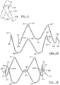
FIG. 1 is a side view of a wire for use in constructing a stent ring in accordance with one embodiment of the present disclosure; -
FIG. 2 is a perspective view of a tubular connector in accordance with an embodiment of the present disclosure; -
FIG. 3A is a perspective view of an end of a wire extending through a tubular connector in accordance with an embodiment of the present disclosure; -
FIG. 3B is a side view of an end of a wire defining a barb extending through a tubular connector in accordance with another embodiment of the present disclosure; -
FIG. 3C is a perspective view of the barb depicted inFIG. 3B ; -
FIG. 4 is a view of a stent ring formed of wires and tubular connectors in accordance with the principles of the present disclosure; -
FIG. 5A is a side view of another embodiment of a wire for use in a stent; -
FIG. 5B is a close up view of the barb of the wire ofFIG. 5A ; -
FIG. 5C is a stent ring constructed of wire segments represented inFIG. 5A ; -
FIG. 6 is a perspective view of a strut arrangement of a stent constructed in a further embodiment of the present disclosure; -
FIG. 7A is a side view of a pair of wire segments for making a stent ring in accordance with the principles of another embodiment of the present disclosure; -
FIG. 7B is a stent ring constructed of the wire segments ofFIG. 7A ; -
FIG. 8 is a stent ring constructed in accordance with another embodiment of the present disclosure; and -
FIG. 9 is a side view of another wire for use in constructing a device in accordance with another embodiment of the present disclosure. - The drawings are purely schematic illustrations of various aspects of the device and method being described, and are not necessarily to scale, unless expressly stated.
- The terms "substantially" or "about" used herein with reference to a quantity includes variations in the recited quantity that are equivalent to the quantity recited, such as an amount that is equivalent to the quantity recited for an intended purpose or function. "Substantially" or derivatives thereof will be understood to mean significantly or in large part. When used in the context of a numerical value or range set forth, "about" or "substantially" means a variation of ±15%, or less, of the numerical value. For example, a value differing by ±15%, ±14%, ±10%, or ±5%, among others, would satisfy the definition of "about" or "substantially."
-
FIG. 1 illustrates a wire 10 that may be used in the construction of a stent ring in accordance with one embodiment of the present disclosure. The illustrated wire 10 extends from afirst end 12 to asecond end 14 and defines awire body 16 therebetween. As illustrated inFIG. 1 , the wire 10 may terminate in abarb 18; in this case, thesecond end 14 is sharpened to a point to define thebarb 18. Thebarb 18 may also be bent away from the remainder of thewire body 16 atbend 36. - In some embodiments, the
barb 18 could be manufactured by grinding the wire to a point. In some embodiments, the angle of projection of thebarb 18 from thewire body 16 may be formed by heat setting thewire body 16 while bent over a mandrel or a ledge. - The
wire body 16 as illustrated inFIG. 1 includes afirst bend 17 and asecond bend 19. When the wire 10 is used in constructing a stent ring, thefirst bend 17 may define a peak of the stent ring, and thesecond bend 19 may define another peak of the stent ring (for example, on the opposite end, longitudinally, of the stent ring.) - In the illustrated embodiment, the
first bend 17 has a smaller radius of curvature than does second bend 19. In another embodiment in which a wire has multiple bends, all bends may have substantially the same radius of curvature. In other embodiments, a wire for use in a constructing a stent ring may have only a single bend. In other embodiments, a wire may have more than two bends, and each bend may have a different radius of curvature, or any combination of radii of curvature. - A wire 10 for use in constructing a stent ring in accordance with the principles of the present disclosure may be made of a variety of different materials. Because the stent ring is intended to be an intraluminal implant for a body vessel, the wire 10 may be made of a biocompatible material, or may have a coating to improve its biocompatibility. In one embodiment, the wire 10 may comprise steel, such as 304 stainless steel. In another embodiment, the wire 10 may comprise a shape memory material, including a shape memory alloy selected from among a nickel-titanium alloy, a cobalt-chromium alloy, and other suitable alloys as are known in the art.
- The wire 10 for use in the stent rings described herein may be manufactured in a number of ways. In an embodiment wherein the wire comprises a shape memory alloy, the wire 10 may be manufactured by heat setting a nitinol wire around a cylindrical mandrel, or in a flat pattern. In another embodiment, a precursor length of wire may be formed into a shape which substantially resembles the finished shape of the intact stent ring, optionally formed and heat set to shape about a mandrel, and then cut into separate segments. The ends of these segments may then be formed into barbs as appropriate.
-
FIG. 2 illustrates atubular connector 20 constructed in accordance with an embodiment of the present disclosure. Theconnector 20 extends from afirst connector end 22 to asecond connector end 24. The body of theconnector 20 defines awall 27 and surrounds alumen 26 that runs through the body of theconnector 20. Theconnector 20, being a tubular member, also defines a longitudinal axis running therethrough, which passes through thelumen 26 and extends throughfirst connector end 22 andsecond connector end 22. As with the wire, atubular connector 20 may be made of any suitable material, including stainless steel, a shape memory material, a polymer, or any other biocompatible material as is known in the art. Thetubular connector 20 may be made from a precursor cannula in some embodiments. - The
tubular connector 20 also defines at least oneside aperture 28 through thewall 27, which is located on the body of theconnector 20 betweenfirst connector end 22 andsecond connector end 24. Theside aperture 28 can be formed through thewall 27 in a number of ways, including machining, laser cutting, and grinding. - The
tubular connector 20 may function to join wires 10 in the assembly of the stent ring. Thetubular connector 20 may have at least one open end atfirst connector end 22 orsecond connector end 24, or two open ends at both connector ends 22 and 24, in order to facilitate the entry of portions of wires 10. Theside aperture 28 of thetubular connector 20 allows for the egress of a portion of the wire 10, such assecond end 14 of the wire 10, through thetubular connector 20, in order to form a barb or other protruding portion of the wire 10. - In the embodiment of
FIG. 3A , aportion 34a of thefirst wire 10a extends throughfirst end 22 of thetubular connector 20 intolumen 26, and aportion 32a extends into the including thesecond end 14a of thewire 10a passes through theside aperture 28 to formbarb 18a. Asecond wire 10b extends throughsecond connector end 24 and intolumen 26, such thattubular connector 20 bridges the twowires 10a/10b. -
FIG. 3B is another view of thebarb 18a andconnector 20 ofFIG. 3A . As can be seen inFIG. 3B , thewire 10a includes theportion 34a within the connector and theportion 32a which protrudes out from theconnector 20 at a defined angle from the path of the strut due tobend 36a. Theend 14a terminates at a point to formbarb 18a. - The properties of the
tubular connector 20 may be adjusted in order to meet the needs of the application for which the implant is to be used. For example, the length of the slotted portion relative to the unslotted portion can be modified according to the location of the barb on the strut, and can be tailored in view of the quantity of barbs to be employed. The overall length of thetubular connector 20 may be adjusted based on the amount of support it will need to provide to the stent structure, and with consideration to the density of material that will be present when the device containing the stent ring is deployed, and so forth. - Another embodiment of a wire-and-
connector assembly 30 is illustrated inFIG. 3C . In this embodiment, the first wire 10c does not terminate in barb; rather, end 18c is simply the unmodified end of the wire 10c. Such a construct may be useful when the wire 10c is of small enough diameter that the end 18c functions to anchor the stent ring even without sharpening, thereby substantially functioning as a barb. - Although the illustrated embodiments portray wires 10 and tubular connectors of a round cross section, it will be noted that other cross sectional profiles for these components (for example, square-shaped and triangular) may be appropriate for various applications.
-
FIG. 4 illustrates a stent ring 40 made up of fivewires 10a-e according to an embodiment of the present disclosure. Thewires 10a-e are interconnected with one another in the same manner as is illustrated inFIGs. 3A-C . Fivewires 10a-e are connected via fivetubular connectors 20a-e. The first bends 17a-e represent a series offirst peaks 42 of the stent ring 40, andsecond bends 19a-e represent a series ofsecond peaks 44 of the stent ring 40 on the opposite longitudinal end of the stent ring 40. In some instances, thefirst peaks 42 may be proximal peaks, and the second peaks may be distal peaks, or vice versa. - The stent ring 40 may be made by fixing the wires into the lumen of the tubular connectors. In one embodiment, the wire may be laser welded to the tubular connector. In another embodiment, a biocompatible adhesive may be used to secure the wire to the tubular connector.
- A stent ring 40 as shown in
FIG. 4 may be used in a variety of medical implants. In one embodiment, the implant may be a stent. In another embodiment, the implant may be a stent graft. In a particular embodiment, a stent ring 40 as inFIG. 4 may be placed such that it is the end ring of a stent graft. The orientation of thebarbs 18a-e, away from the direction in which the end ring of a stent graft would extend, provides anchoring for the stent graft when deployed. - The stent ring 40 as shown in
FIG. 4 has fivewires 10a-e, fiveconnectors 20a-e, and fivebarbs 18a-e. Such a stent ring as depicted has fiveupper peaks 17a-e and fivelower peaks 19a-e. It will be appreciated that a stent ring in accordance with the principles of the present disclosure need not have an equal number of wires, peaks, and barbs; that is, in certain cases it may be preferred to have no barb extend from a connector, for instance. - A stent ring 40 made of wires 10 that have a
barb 18 formed at the end may yield increased barb fatigue performance compared to other barb attachment methods that involve joining a separate barb to a device, such as soldering. Because the wire and the barb are unitary, the barb, wire, and stent ring may be easier to manufacture, compared to welding or soldering a separate component to the strut or ring. - A stent ring made from wire terminating at an end in a barb may have improved packing density. The combination of a tubular connector with a wire terminating in a barb that extends through a side aperture of the tubular connector may have a lower overall diameter (such as about 0.6 mm) compared to an exemplary laser-cut barb (which may have a diameter of about 1.05 mm).
- Making a barb from the end of a precursor piece of wire also allows for adjustable barb lengths and diameters, unlike cannula cut barbs, the dimensions of which are constrained by the length and width of the strut from which they are cut, the barb of a construction according to the principles of the present disclosure can be terminated at various lengths and can be ground down to a variety of diameters.
-
FIG. 5A illustrates another embodiment of awire 110 in accordance with the principles of the present disclosure. The wire ofFIG. 5A resembles that ofFIG. 1 , except thebend 136 is a U-shaped looping of thewire body 116. In this embodiment, and as shown inFIG. 5B , thewire 110a may extend through thetubular connector 120, and thebarb 118a emerge through the side aperture 128, forming an acute angle relative to the portion of the wire body 116a from which it extends, in contrast to the obtuse angle formed in the wire 10 illustrated inFIG. 1 . Astent ring 140 made ofwires 110a-e is illustrated inFIG. 5C . -
FIG. 6 illustrates a connection in accordance with another embodiment of the present invention. In this embodiment, twowires 210 and 210b are crimped together side-by-side in a singletubular connector 220. The wires themselves may be fused by welding or another attachment mechanism, and thetubular connector 220 may be sized such that the cannula itself is not secured to thewires 210a/210b. Thewires 210a/210b may also be attached to one another or to theconnector 220 by an adhesive or any other connection mechanism known in the art. -
FIG. 7A illustrates twowires wire 310 has twoupper peaks 317 and threelower peaks 319, and thewire 320 has threeupper peaks 327 and twolower peaks 329, such that when connected by twotubular connectors barbs 318/328, but five upper and lower peaks as in the embodiment ofFIG. 4 . -
FIG. 8 illustrates another embodiment of a stent ring. In thisstent ring 440, the position oftubular connectors 420a-e are varied in the longitudinal dimension. As shown,barb 418a extends such that it terminates at a point which is a distance Y from thelower peak 419b toward which it points. This distance Y is less than a distance X, which is the distance betweenpeak 419a andbarb 418e. Distance Z, between barb 418c andpeak 419d, is greater even than distance X. Distributing the connectors in the longitudinal dimension may assist with packing density of the implant when compressed as the connectors increase the diameter of the stent struts. -
FIG. 9 illustrates another embodiment of awire 510 that may be employed in the construction of a stent ring. Unlike the wire ofFIG. 1 , which is substantially constant in diameter along its length except for the barb itself, thewire 510 ofFIG. 9 has a thinnedzone 560 in which the wire tapers prior to thebend 536. The width w1 of the main portion of thewire 510 is greater than w2 of the thinnedzone 560. Such thinning may assist in making a more labile barb for uses in which more flexibility of the barb is desirable. - As a person skilled in the art will readily appreciate, the above description is only meant as an illustration of implementation of the principles this application. This description is not intended to limit the scope of this application in that the system is susceptible to modification, variation and change, without departing from the spirit of this application, as defined in the following claims.
- An aspect of the disclosure provides stent for implantation into a body vessel, the stent comprising: a first wire extending from a first terminal end to a second terminal end, a body extending from the first terminal end to the second terminal end, and at least one bend in the body; and a tubular connector having a first end, a second end, a connector body between the first end and the second end, a lumen, a longitudinal axis, and a side aperture in a wall of the connector body between the first end and the second end, wherein at least one of the first end and the second end is an open end in fluid communication with the lumen; wherein a portion of the first wire is disposed in the lumen of the connector and an end of the first wire is disposed through the aperture and extends outwardly from the wall of connector, and wherein the at least one bend defines a peak of a stent ring. The end of the wire disposed through the aperture may comprise a barb. The stent ring may comprise the first wire and a second wire. The stent ring may comprise a plurality of tubular connectors. The body may comprise a first bend and a second bend, each of the first bend and the second bend defining a peak of the stent ring. The first bend may have a first radius of curvature and the second bend has a second radius of curvature, the first radius of curvature being different from the second radius of curvature. The first end and the second end of the tubular connector may be open ends. A portion of the first wire may be disposed through the first end of the tubular connector, and a portion of a second wire may be disposed through the second end of the tubular connector. The portion may extend at an acute angle relative to the longitudinal axis of the tubular connector. The portion may be bent to define an obtuse angle relative to the longitudinal axis of the tubular connector. The first wire may comprises a shape-memory material, for example the shape-memory material may be selected from a nickel-titanium alloy and a cobalt-chromium alloy. The stent may comprise a portion of a stent graft.
- An aspect of the disclosure also provides a stent for implantation into a body vessel, the stent comprising: a first wire extending from a first terminal end to a second terminal end, a body extending from the first terminal end to the second terminal end, at least one bend in the body, and the second terminal end of the wire defining a barb; and a tubular connector having a first end and a second end, a connector body between the first end and the second end, a lumen, a longitudinal axis, a side aperture in a wall of the connector body between the first end and the second end, wherein at least one of the first end and the second end is an open end in fluid communication with the lumen; wherein a portion of the first wire is disposed in the lumen of the connector and the barb is disposed through the aperture of the connector and extends outwardly from the connector, and wherein the at least one bend defines a peak of a stent ring. The stent ring may comprise a second wire. The stent ring may also comprise a plurality of tubular connectors. The first wire may comprise a first bend and a second bend, each of the first bend and the second bend defining a peak of the stent ring. The first end and the second end of the tubular connector may be open ends. A portion of the first wire may be disposed through the first end of the tubular connector, and a portion of a second wire is disposed through the second end of the tubular connector.
- An aspect provides a method of making a stent, the method comprising: forming a stent ring with a wire and a tubular connector, the wire extending from a first terminal end to a second terminal end defining a wire body therebetween, the second terminal end comprising a barb, the wire body defining at least one bend therein; the tubular connector having a first end, a second end, a connector body between the first end and the second end, a lumen, a longitudinal axis, a side aperture in a wall of the connector body between the first end and the second end, wherein at least one of the first end and the second end is an open end in fluid communication with the lumen; the stent ring being formed such that a portion of the wire is disposed in the lumen of the tubular connector and the barb is disposed through the side aperture of the connector and extends outwardly from the wall of the connector, the at least one bend defining a peak of the stent ring.
- Disclosed herein is a stent which includes stent ring structures made up of at least one wire and at least one tubular connector through which a portion of the wire is disposed. The tubular connector includes a side wall with an aperture formed therethrough. A portion of the wire extends therethrough and acts as a barb. A method of making such a stent is also disclosed.
Claims (15)
- A stent for implantation into a body vessel, the stent comprising:a first wire extending from a first terminal end to a second terminal end, a body extending from the first terminal end to the second terminal end, and at least one bend in the body; anda tubular connector having a first end, a second end, a connector body between the first end and the second end, a lumen, a longitudinal axis, and a side aperture in a wall of the connector body between the first end and the second end, wherein at least one of the first end and the second end is an open end in fluid communication with the lumen;wherein a portion of the first wire is disposed in the lumen of the connector and an end of the first wire is disposed through the aperture and extends outwardly from the wall of connector, and wherein the at least one bend defines a peak of a stent ring.
- The stent of claim 1, wherein the end of the wire disposed through the aperture comprises a barb.
- The stent of claim 1 or 2, wherein the stent ring comprises at least one of: (i) the first wire and a second wire, and (ii) a plurality of tubular connectors.
- The stent of any preceding claim, wherein the body comprises a first bend and a second bend, each of the first bend and the second bend defining a peak of the stent ring, for example wherein the first bend has a first radius of curvature and the second bend has a second radius of curvature, the first radius of curvature being different from the second radius of curvature.
- The stent of any preceding claim, wherein the first end and the second end of the tubular connector are open ends, for example wherein a portion of the first wire is disposed through the first end of the tubular connector, and a portion of a second wire is disposed through the second end of the tubular connector.
- The stent of any preceding claim wherein the portion extends at an acute angle relative to the longitudinal axis of the tubular connector.
- The stent of any preceding claim wherein the portion is bent to define an obtuse angle relative to the longitudinal axis of the tubular connector.
- The stent of any preceding claim wherein the first wire comprises a shape-memory material, for example wherein the shape-memory material is selected from a nickel-titanium alloy and a cobalt-chromium alloy.
- The stent of any preceding claim wherein the stent comprises a portion of a stent graft.
- The stent of any preceding claim wherein the second terminal end of the wire defines a barb and the barb is disposed through the aperture of the connector and extends outwardly from the connector.
- The stent of claim 10, wherein the stent ring comprises a second wire, for example wherein the stent ring comprises a plurality of tubular connectors.
- The stent of claim 10 or 11, wherein the first wire comprises a first bend and a second bend, each of the first bend and the second bend defining a peak of the stent ring.
- The stent of any of claims 10 to 12, wherein the first end and the second end of the tubular connector are open ends.
- The stent of any of claims 10 to 13 wherein a portion of the first wire is disposed through the first end of the tubular connector, and a portion of a second wire is disposed through the second end of the tubular connector.
- A method of making a stent, the method comprising:
forming a stent ring with a wire and a tubular connector,the wire extending from a first terminal end to a second terminal end defining a wire body therebetween, the second terminal end comprising a barb, the wire body defining at least one bend therein;the tubular connector having a first end, a second end, a connector body between the first end and the second end, a lumen, a longitudinal axis, a side aperture in a wall of the connector body between the first end and the second end, wherein at least one of the first end and the second end is an open end in fluid communication with the lumen;the stent ring being formed such that a portion of the wire is disposed in the lumen of the tubular connector and the barb is disposed through the side aperture of the connector and extends outwardly from the wall of the connector, the at least one bend defining a peak of the stent ring.
Applications Claiming Priority (1)
| Application Number | Priority Date | Filing Date | Title |
|---|---|---|---|
| US201862616129P | 2018-01-11 | 2018-01-11 |
Publications (2)
| Publication Number | Publication Date |
|---|---|
| EP3510976A1 true EP3510976A1 (en) | 2019-07-17 |
| EP3510976B1 EP3510976B1 (en) | 2020-09-09 |
Family
ID=65019438
Family Applications (1)
| Application Number | Title | Priority Date | Filing Date |
|---|---|---|---|
| EP19151493.4A Active EP3510976B1 (en) | 2018-01-11 | 2019-01-11 | Barbed wire stent |
Country Status (2)
| Country | Link |
|---|---|
| US (1) | US10959864B2 (en) |
| EP (1) | EP3510976B1 (en) |
Families Citing this family (4)
| Publication number | Priority date | Publication date | Assignee | Title |
|---|---|---|---|---|
| US11219459B2 (en) * | 2018-04-17 | 2022-01-11 | David Ruebeck | Device and method for connecting tubular structures |
| USD952854S1 (en) * | 2019-02-28 | 2022-05-24 | Olympus Corporation | Stent |
| USD987826S1 (en) * | 2021-03-15 | 2023-05-30 | The Corporation Of Mercer University | Patmas weave stent |
| USD987080S1 (en) * | 2021-09-16 | 2023-05-23 | The Corporation Of Mercer University | Patmas lantern stent |
Citations (4)
| Publication number | Priority date | Publication date | Assignee | Title |
|---|---|---|---|---|
| WO1999043379A1 (en) * | 1998-02-26 | 1999-09-02 | Board Of Regents, The University Of Texas System | Delivery system and method for deployment and endovascular assembly of multi-stage stent graft |
| WO2004016201A2 (en) * | 2002-08-15 | 2004-02-26 | Cook Incorporated | Stent and method of forming a stent with integral barbs |
| US20090171442A1 (en) * | 2007-12-27 | 2009-07-02 | Cook Incorporated | Z-stent with incorporated barbs |
| WO2017036207A1 (en) * | 2015-09-02 | 2017-03-09 | 先健科技(深圳)有限公司 | Implantable medical instrument |
Family Cites Families (13)
| Publication number | Priority date | Publication date | Assignee | Title |
|---|---|---|---|---|
| EP0657147B1 (en) | 1993-11-04 | 1999-08-04 | C.R. Bard, Inc. | Non-migrating vascular prosthesis |
| FR2737404B1 (en) | 1995-08-03 | 1997-09-19 | Braun Celsa Sa | PROSTHESIS IMPLANTABLE IN A HUMAN OR ANIMAL CONDUCT, SUCH AS A WALL Expander, OR ANEURISM PROSTHESIS |
| DK174814B1 (en) | 1998-02-25 | 2003-12-01 | Cook William Europ | stent device |
| WO1999062431A1 (en) | 1998-06-02 | 1999-12-09 | Cook Incorporated | Multiple-sided intraluminal medical device |
| US7452371B2 (en) | 1999-06-02 | 2008-11-18 | Cook Incorporated | Implantable vascular device |
| US7828839B2 (en) * | 2002-05-16 | 2010-11-09 | Cook Incorporated | Flexible barb for anchoring a prosthesis |
| US20040117004A1 (en) | 2002-05-16 | 2004-06-17 | Osborne Thomas A. | Stent and method of forming a stent with integral barbs |
| DE10337739B4 (en) | 2003-08-12 | 2009-11-26 | Jotec Gmbh | Stent for implantation in a blood vessel, especially in the area of the aortic arch |
| US7476256B2 (en) | 2003-12-09 | 2009-01-13 | Gi Dynamics, Inc. | Intestinal sleeve |
| US8292946B2 (en) | 2005-10-25 | 2012-10-23 | Boston Scientific Scimed, Inc. | Medical implants with limited resistance to migration |
| US8409271B2 (en) | 2006-07-25 | 2013-04-02 | Mani, Inc. | Stent having a locking part which prevents the strut from sliding out of the junction pipe |
| US8870947B2 (en) * | 2011-09-16 | 2014-10-28 | W.L. Gore & Associates, Inc. | Medical device fixation anchors |
| EP3167845A1 (en) | 2015-11-12 | 2017-05-17 | The Provost, Fellows, Foundation Scholars, & the other members of Board, of the College of Holy and Undiv. Trinity of Queen Elizabeth near Dublin | An implantable biocompatible expander suitable for treatment of constrictions of body lumen |
-
2019
- 2019-01-11 EP EP19151493.4A patent/EP3510976B1/en active Active
- 2019-01-11 US US16/245,351 patent/US10959864B2/en active Active
Patent Citations (4)
| Publication number | Priority date | Publication date | Assignee | Title |
|---|---|---|---|---|
| WO1999043379A1 (en) * | 1998-02-26 | 1999-09-02 | Board Of Regents, The University Of Texas System | Delivery system and method for deployment and endovascular assembly of multi-stage stent graft |
| WO2004016201A2 (en) * | 2002-08-15 | 2004-02-26 | Cook Incorporated | Stent and method of forming a stent with integral barbs |
| US20090171442A1 (en) * | 2007-12-27 | 2009-07-02 | Cook Incorporated | Z-stent with incorporated barbs |
| WO2017036207A1 (en) * | 2015-09-02 | 2017-03-09 | 先健科技(深圳)有限公司 | Implantable medical instrument |
Also Published As
| Publication number | Publication date |
|---|---|
| US10959864B2 (en) | 2021-03-30 |
| US20190209352A1 (en) | 2019-07-11 |
| EP3510976B1 (en) | 2020-09-09 |
Similar Documents
| Publication | Publication Date | Title |
|---|---|---|
| EP3510976B1 (en) | Barbed wire stent | |
| US12290458B2 (en) | Stents having a hybrid pattern and methods of manufacture | |
| US10363154B2 (en) | Stent designs for use with one or more trigger wires | |
| US7736387B2 (en) | Mechanism for securing to a corporeal lumen and method of manufacturing | |
| EP3445283B1 (en) | Stent-graft prosthesis and method of manufacture | |
| US9237959B2 (en) | Stent and barb | |
| US10588765B2 (en) | Uniformly expandable stent | |
| US6214025B1 (en) | Self-centering, self-expanding and retrievable vena cava filter | |
| EP3115021B1 (en) | Helical stent having improved flexibility and expandability | |
| JP3894332B2 (en) | Expandable medical device | |
| US8840659B2 (en) | Stent and stent-graft designs | |
| US7993388B2 (en) | Stent with offset cell geometry | |
| US6565597B1 (en) | Stent adapted for tangle-free deployment | |
| US20090149946A1 (en) | Stent having at least one barb and methods of manufacture | |
| CA2494970A1 (en) | Stent and method of forming a stent with integral barbs | |
| US9770350B2 (en) | Stent-graft with fixation elements that are radially confined for delivery | |
| US20170258610A9 (en) | Self expanding stent | |
| CN102548506A (en) | Bifurcated highly conformable medical device branch access | |
| US20170035589A1 (en) | Monolithic medical devices and methods of use | |
| AU2018264124A1 (en) | Monolithic medical device, methods of making and using the same | |
| EP3603583A1 (en) | Spring barb for medical device | |
| US9173754B2 (en) | Stent |
Legal Events
| Date | Code | Title | Description |
|---|---|---|---|
| PUAI | Public reference made under article 153(3) epc to a published international application that has entered the european phase |
Free format text: ORIGINAL CODE: 0009012 |
|
| STAA | Information on the status of an ep patent application or granted ep patent |
Free format text: STATUS: THE APPLICATION HAS BEEN PUBLISHED |
|
| AK | Designated contracting states |
Kind code of ref document: A1 Designated state(s): AL AT BE BG CH CY CZ DE DK EE ES FI FR GB GR HR HU IE IS IT LI LT LU LV MC MK MT NL NO PL PT RO RS SE SI SK SM TR |
|
| AX | Request for extension of the european patent |
Extension state: BA ME |
|
| STAA | Information on the status of an ep patent application or granted ep patent |
Free format text: STATUS: REQUEST FOR EXAMINATION WAS MADE |
|
| 17P | Request for examination filed |
Effective date: 20200117 |
|
| RBV | Designated contracting states (corrected) |
Designated state(s): AL AT BE BG CH CY CZ DE DK EE ES FI FR GB GR HR HU IE IS IT LI LT LU LV MC MK MT NL NO PL PT RO RS SE SI SK SM TR |
|
| GRAP | Despatch of communication of intention to grant a patent |
Free format text: ORIGINAL CODE: EPIDOSNIGR1 |
|
| STAA | Information on the status of an ep patent application or granted ep patent |
Free format text: STATUS: GRANT OF PATENT IS INTENDED |
|
| INTG | Intention to grant announced |
Effective date: 20200325 |
|
| GRAS | Grant fee paid |
Free format text: ORIGINAL CODE: EPIDOSNIGR3 |
|
| GRAA | (expected) grant |
Free format text: ORIGINAL CODE: 0009210 |
|
| STAA | Information on the status of an ep patent application or granted ep patent |
Free format text: STATUS: THE PATENT HAS BEEN GRANTED |
|
| AK | Designated contracting states |
Kind code of ref document: B1 Designated state(s): AL AT BE BG CH CY CZ DE DK EE ES FI FR GB GR HR HU IE IS IT LI LT LU LV MC MK MT NL NO PL PT RO RS SE SI SK SM TR |
|
| REG | Reference to a national code |
Ref country code: GB Ref legal event code: FG4D |
|
| REG | Reference to a national code |
Ref country code: AT Ref legal event code: REF Ref document number: 1310630 Country of ref document: AT Kind code of ref document: T Effective date: 20200915 Ref country code: CH Ref legal event code: EP |
|
| REG | Reference to a national code |
Ref country code: IE Ref legal event code: FG4D |
|
| REG | Reference to a national code |
Ref country code: DE Ref legal event code: R096 Ref document number: 602019000562 Country of ref document: DE |
|
| REG | Reference to a national code |
Ref country code: LT Ref legal event code: MG4D |
|
| PG25 | Lapsed in a contracting state [announced via postgrant information from national office to epo] |
Ref country code: NO Free format text: LAPSE BECAUSE OF FAILURE TO SUBMIT A TRANSLATION OF THE DESCRIPTION OR TO PAY THE FEE WITHIN THE PRESCRIBED TIME-LIMIT Effective date: 20201209 Ref country code: LT Free format text: LAPSE BECAUSE OF FAILURE TO SUBMIT A TRANSLATION OF THE DESCRIPTION OR TO PAY THE FEE WITHIN THE PRESCRIBED TIME-LIMIT Effective date: 20200909 Ref country code: BG Free format text: LAPSE BECAUSE OF FAILURE TO SUBMIT A TRANSLATION OF THE DESCRIPTION OR TO PAY THE FEE WITHIN THE PRESCRIBED TIME-LIMIT Effective date: 20201209 Ref country code: FI Free format text: LAPSE BECAUSE OF FAILURE TO SUBMIT A TRANSLATION OF THE DESCRIPTION OR TO PAY THE FEE WITHIN THE PRESCRIBED TIME-LIMIT Effective date: 20200909 Ref country code: GR Free format text: LAPSE BECAUSE OF FAILURE TO SUBMIT A TRANSLATION OF THE DESCRIPTION OR TO PAY THE FEE WITHIN THE PRESCRIBED TIME-LIMIT Effective date: 20201210 Ref country code: HR Free format text: LAPSE BECAUSE OF FAILURE TO SUBMIT A TRANSLATION OF THE DESCRIPTION OR TO PAY THE FEE WITHIN THE PRESCRIBED TIME-LIMIT Effective date: 20200909 Ref country code: SE Free format text: LAPSE BECAUSE OF FAILURE TO SUBMIT A TRANSLATION OF THE DESCRIPTION OR TO PAY THE FEE WITHIN THE PRESCRIBED TIME-LIMIT Effective date: 20200909 |
|
| REG | Reference to a national code |
Ref country code: AT Ref legal event code: MK05 Ref document number: 1310630 Country of ref document: AT Kind code of ref document: T Effective date: 20200909 |
|
| REG | Reference to a national code |
Ref country code: NL Ref legal event code: MP Effective date: 20200909 |
|
| PG25 | Lapsed in a contracting state [announced via postgrant information from national office to epo] |
Ref country code: LV Free format text: LAPSE BECAUSE OF FAILURE TO SUBMIT A TRANSLATION OF THE DESCRIPTION OR TO PAY THE FEE WITHIN THE PRESCRIBED TIME-LIMIT Effective date: 20200909 Ref country code: RS Free format text: LAPSE BECAUSE OF FAILURE TO SUBMIT A TRANSLATION OF THE DESCRIPTION OR TO PAY THE FEE WITHIN THE PRESCRIBED TIME-LIMIT Effective date: 20200909 Ref country code: PL Free format text: LAPSE BECAUSE OF FAILURE TO SUBMIT A TRANSLATION OF THE DESCRIPTION OR TO PAY THE FEE WITHIN THE PRESCRIBED TIME-LIMIT Effective date: 20200909 |
|
| PG25 | Lapsed in a contracting state [announced via postgrant information from national office to epo] |
Ref country code: EE Free format text: LAPSE BECAUSE OF FAILURE TO SUBMIT A TRANSLATION OF THE DESCRIPTION OR TO PAY THE FEE WITHIN THE PRESCRIBED TIME-LIMIT Effective date: 20200909 Ref country code: PT Free format text: LAPSE BECAUSE OF FAILURE TO SUBMIT A TRANSLATION OF THE DESCRIPTION OR TO PAY THE FEE WITHIN THE PRESCRIBED TIME-LIMIT Effective date: 20210111 Ref country code: RO Free format text: LAPSE BECAUSE OF FAILURE TO SUBMIT A TRANSLATION OF THE DESCRIPTION OR TO PAY THE FEE WITHIN THE PRESCRIBED TIME-LIMIT Effective date: 20200909 Ref country code: CZ Free format text: LAPSE BECAUSE OF FAILURE TO SUBMIT A TRANSLATION OF THE DESCRIPTION OR TO PAY THE FEE WITHIN THE PRESCRIBED TIME-LIMIT Effective date: 20200909 Ref country code: SM Free format text: LAPSE BECAUSE OF FAILURE TO SUBMIT A TRANSLATION OF THE DESCRIPTION OR TO PAY THE FEE WITHIN THE PRESCRIBED TIME-LIMIT Effective date: 20200909 |
|
| PG25 | Lapsed in a contracting state [announced via postgrant information from national office to epo] |
Ref country code: IS Free format text: LAPSE BECAUSE OF FAILURE TO SUBMIT A TRANSLATION OF THE DESCRIPTION OR TO PAY THE FEE WITHIN THE PRESCRIBED TIME-LIMIT Effective date: 20210109 Ref country code: AT Free format text: LAPSE BECAUSE OF FAILURE TO SUBMIT A TRANSLATION OF THE DESCRIPTION OR TO PAY THE FEE WITHIN THE PRESCRIBED TIME-LIMIT Effective date: 20200909 Ref country code: AL Free format text: LAPSE BECAUSE OF FAILURE TO SUBMIT A TRANSLATION OF THE DESCRIPTION OR TO PAY THE FEE WITHIN THE PRESCRIBED TIME-LIMIT Effective date: 20200909 Ref country code: ES Free format text: LAPSE BECAUSE OF FAILURE TO SUBMIT A TRANSLATION OF THE DESCRIPTION OR TO PAY THE FEE WITHIN THE PRESCRIBED TIME-LIMIT Effective date: 20200909 |
|
| REG | Reference to a national code |
Ref country code: DE Ref legal event code: R097 Ref document number: 602019000562 Country of ref document: DE |
|
| PG25 | Lapsed in a contracting state [announced via postgrant information from national office to epo] |
Ref country code: SK Free format text: LAPSE BECAUSE OF FAILURE TO SUBMIT A TRANSLATION OF THE DESCRIPTION OR TO PAY THE FEE WITHIN THE PRESCRIBED TIME-LIMIT Effective date: 20200909 |
|
| PLBE | No opposition filed within time limit |
Free format text: ORIGINAL CODE: 0009261 |
|
| STAA | Information on the status of an ep patent application or granted ep patent |
Free format text: STATUS: NO OPPOSITION FILED WITHIN TIME LIMIT |
|
| 26N | No opposition filed |
Effective date: 20210610 |
|
| PG25 | Lapsed in a contracting state [announced via postgrant information from national office to epo] |
Ref country code: DK Free format text: LAPSE BECAUSE OF FAILURE TO SUBMIT A TRANSLATION OF THE DESCRIPTION OR TO PAY THE FEE WITHIN THE PRESCRIBED TIME-LIMIT Effective date: 20200909 Ref country code: SI Free format text: LAPSE BECAUSE OF FAILURE TO SUBMIT A TRANSLATION OF THE DESCRIPTION OR TO PAY THE FEE WITHIN THE PRESCRIBED TIME-LIMIT Effective date: 20200909 Ref country code: MC Free format text: LAPSE BECAUSE OF FAILURE TO SUBMIT A TRANSLATION OF THE DESCRIPTION OR TO PAY THE FEE WITHIN THE PRESCRIBED TIME-LIMIT Effective date: 20200909 |
|
| PG25 | Lapsed in a contracting state [announced via postgrant information from national office to epo] |
Ref country code: LU Free format text: LAPSE BECAUSE OF NON-PAYMENT OF DUE FEES Effective date: 20210111 |
|
| REG | Reference to a national code |
Ref country code: BE Ref legal event code: MM Effective date: 20210131 |
|
| PG25 | Lapsed in a contracting state [announced via postgrant information from national office to epo] |
Ref country code: FR Free format text: LAPSE BECAUSE OF NON-PAYMENT OF DUE FEES Effective date: 20210131 Ref country code: IT Free format text: LAPSE BECAUSE OF FAILURE TO SUBMIT A TRANSLATION OF THE DESCRIPTION OR TO PAY THE FEE WITHIN THE PRESCRIBED TIME-LIMIT Effective date: 20200909 |
|
| PG25 | Lapsed in a contracting state [announced via postgrant information from national office to epo] |
Ref country code: BE Free format text: LAPSE BECAUSE OF NON-PAYMENT OF DUE FEES Effective date: 20210131 |
|
| REG | Reference to a national code |
Ref country code: CH Ref legal event code: PL |
|
| PG25 | Lapsed in a contracting state [announced via postgrant information from national office to epo] |
Ref country code: LI Free format text: LAPSE BECAUSE OF NON-PAYMENT OF DUE FEES Effective date: 20220131 Ref country code: CH Free format text: LAPSE BECAUSE OF NON-PAYMENT OF DUE FEES Effective date: 20220131 |
|
| PG25 | Lapsed in a contracting state [announced via postgrant information from national office to epo] |
Ref country code: NL Free format text: LAPSE BECAUSE OF NON-PAYMENT OF DUE FEES Effective date: 20200923 Ref country code: CY Free format text: LAPSE BECAUSE OF FAILURE TO SUBMIT A TRANSLATION OF THE DESCRIPTION OR TO PAY THE FEE WITHIN THE PRESCRIBED TIME-LIMIT Effective date: 20200909 |
|
| P01 | Opt-out of the competence of the unified patent court (upc) registered |
Effective date: 20230602 |
|
| PG25 | Lapsed in a contracting state [announced via postgrant information from national office to epo] |
Ref country code: HU Free format text: LAPSE BECAUSE OF FAILURE TO SUBMIT A TRANSLATION OF THE DESCRIPTION OR TO PAY THE FEE WITHIN THE PRESCRIBED TIME-LIMIT; INVALID AB INITIO Effective date: 20190111 |
|
| PG25 | Lapsed in a contracting state [announced via postgrant information from national office to epo] |
Ref country code: MK Free format text: LAPSE BECAUSE OF FAILURE TO SUBMIT A TRANSLATION OF THE DESCRIPTION OR TO PAY THE FEE WITHIN THE PRESCRIBED TIME-LIMIT Effective date: 20200909 |
|
| PG25 | Lapsed in a contracting state [announced via postgrant information from national office to epo] |
Ref country code: MT Free format text: LAPSE BECAUSE OF FAILURE TO SUBMIT A TRANSLATION OF THE DESCRIPTION OR TO PAY THE FEE WITHIN THE PRESCRIBED TIME-LIMIT Effective date: 20200909 |
|
| PG25 | Lapsed in a contracting state [announced via postgrant information from national office to epo] |
Ref country code: TR Free format text: LAPSE BECAUSE OF FAILURE TO SUBMIT A TRANSLATION OF THE DESCRIPTION OR TO PAY THE FEE WITHIN THE PRESCRIBED TIME-LIMIT Effective date: 20200909 |
|
| PGFP | Annual fee paid to national office [announced via postgrant information from national office to epo] |
Ref country code: GB Payment date: 20260126 Year of fee payment: 8 |
|
| PGFP | Annual fee paid to national office [announced via postgrant information from national office to epo] |
Ref country code: DE Payment date: 20260127 Year of fee payment: 8 Ref country code: IE Payment date: 20260120 Year of fee payment: 8 |