EP3510654B1 - Porous silicon materials and conductive polymer binder electrodes - Google Patents
Porous silicon materials and conductive polymer binder electrodes Download PDFInfo
- Publication number
- EP3510654B1 EP3510654B1 EP17758876.1A EP17758876A EP3510654B1 EP 3510654 B1 EP3510654 B1 EP 3510654B1 EP 17758876 A EP17758876 A EP 17758876A EP 3510654 B1 EP3510654 B1 EP 3510654B1
- Authority
- EP
- European Patent Office
- Prior art keywords
- electrode
- porous silicon
- conductive polymer
- polymer binder
- porous
- Prior art date
- Legal status (The legal status is an assumption and is not a legal conclusion. Google has not performed a legal analysis and makes no representation as to the accuracy of the status listed.)
- Active
Links
Images



Classifications
-
- H—ELECTRICITY
- H01—ELECTRIC ELEMENTS
- H01M—PROCESSES OR MEANS, e.g. BATTERIES, FOR THE DIRECT CONVERSION OF CHEMICAL ENERGY INTO ELECTRICAL ENERGY
- H01M4/00—Electrodes
- H01M4/02—Electrodes composed of, or comprising, active material
- H01M4/13—Electrodes for accumulators with non-aqueous electrolyte, e.g. for lithium-accumulators; Processes of manufacture thereof
- H01M4/134—Electrodes based on metals, Si or alloys
-
- H—ELECTRICITY
- H01—ELECTRIC ELEMENTS
- H01M—PROCESSES OR MEANS, e.g. BATTERIES, FOR THE DIRECT CONVERSION OF CHEMICAL ENERGY INTO ELECTRICAL ENERGY
- H01M10/00—Secondary cells; Manufacture thereof
- H01M10/05—Accumulators with non-aqueous electrolyte
- H01M10/052—Li-accumulators
-
- H—ELECTRICITY
- H01—ELECTRIC ELEMENTS
- H01M—PROCESSES OR MEANS, e.g. BATTERIES, FOR THE DIRECT CONVERSION OF CHEMICAL ENERGY INTO ELECTRICAL ENERGY
- H01M10/00—Secondary cells; Manufacture thereof
- H01M10/05—Accumulators with non-aqueous electrolyte
- H01M10/052—Li-accumulators
- H01M10/0525—Rocking-chair batteries, i.e. batteries with lithium insertion or intercalation in both electrodes; Lithium-ion batteries
-
- H—ELECTRICITY
- H01—ELECTRIC ELEMENTS
- H01M—PROCESSES OR MEANS, e.g. BATTERIES, FOR THE DIRECT CONVERSION OF CHEMICAL ENERGY INTO ELECTRICAL ENERGY
- H01M4/00—Electrodes
- H01M4/02—Electrodes composed of, or comprising, active material
- H01M4/04—Processes of manufacture in general
- H01M4/0402—Methods of deposition of the material
- H01M4/0409—Methods of deposition of the material by a doctor blade method, slip-casting or roller coating
-
- H—ELECTRICITY
- H01—ELECTRIC ELEMENTS
- H01M—PROCESSES OR MEANS, e.g. BATTERIES, FOR THE DIRECT CONVERSION OF CHEMICAL ENERGY INTO ELECTRICAL ENERGY
- H01M4/00—Electrodes
- H01M4/02—Electrodes composed of, or comprising, active material
- H01M4/13—Electrodes for accumulators with non-aqueous electrolyte, e.g. for lithium-accumulators; Processes of manufacture thereof
- H01M4/133—Electrodes based on carbonaceous material, e.g. graphite-intercalation compounds or CFx
-
- H—ELECTRICITY
- H01—ELECTRIC ELEMENTS
- H01M—PROCESSES OR MEANS, e.g. BATTERIES, FOR THE DIRECT CONVERSION OF CHEMICAL ENERGY INTO ELECTRICAL ENERGY
- H01M4/00—Electrodes
- H01M4/02—Electrodes composed of, or comprising, active material
- H01M4/13—Electrodes for accumulators with non-aqueous electrolyte, e.g. for lithium-accumulators; Processes of manufacture thereof
- H01M4/139—Processes of manufacture
- H01M4/1395—Processes of manufacture of electrodes based on metals, Si or alloys
-
- H—ELECTRICITY
- H01—ELECTRIC ELEMENTS
- H01M—PROCESSES OR MEANS, e.g. BATTERIES, FOR THE DIRECT CONVERSION OF CHEMICAL ENERGY INTO ELECTRICAL ENERGY
- H01M4/00—Electrodes
- H01M4/02—Electrodes composed of, or comprising, active material
- H01M4/36—Selection of substances as active materials, active masses, active liquids
- H01M4/362—Composites
- H01M4/364—Composites as mixtures
-
- H—ELECTRICITY
- H01—ELECTRIC ELEMENTS
- H01M—PROCESSES OR MEANS, e.g. BATTERIES, FOR THE DIRECT CONVERSION OF CHEMICAL ENERGY INTO ELECTRICAL ENERGY
- H01M4/00—Electrodes
- H01M4/02—Electrodes composed of, or comprising, active material
- H01M4/36—Selection of substances as active materials, active masses, active liquids
- H01M4/38—Selection of substances as active materials, active masses, active liquids of elements or alloys
- H01M4/386—Silicon or alloys based on silicon
-
- H—ELECTRICITY
- H01—ELECTRIC ELEMENTS
- H01M—PROCESSES OR MEANS, e.g. BATTERIES, FOR THE DIRECT CONVERSION OF CHEMICAL ENERGY INTO ELECTRICAL ENERGY
- H01M4/00—Electrodes
- H01M4/02—Electrodes composed of, or comprising, active material
- H01M4/62—Selection of inactive substances as ingredients for active masses, e.g. binders, fillers
- H01M4/621—Binders
- H01M4/622—Binders being polymers
-
- H—ELECTRICITY
- H01—ELECTRIC ELEMENTS
- H01M—PROCESSES OR MEANS, e.g. BATTERIES, FOR THE DIRECT CONVERSION OF CHEMICAL ENERGY INTO ELECTRICAL ENERGY
- H01M4/00—Electrodes
- H01M4/02—Electrodes composed of, or comprising, active material
- H01M4/62—Selection of inactive substances as ingredients for active masses, e.g. binders, fillers
- H01M4/624—Electric conductive fillers
- H01M4/625—Carbon or graphite
-
- H—ELECTRICITY
- H01—ELECTRIC ELEMENTS
- H01M—PROCESSES OR MEANS, e.g. BATTERIES, FOR THE DIRECT CONVERSION OF CHEMICAL ENERGY INTO ELECTRICAL ENERGY
- H01M4/00—Electrodes
- H01M4/02—Electrodes composed of, or comprising, active material
- H01M4/64—Carriers or collectors
- H01M4/66—Selection of materials
- H01M4/661—Metal or alloys, e.g. alloy coatings
-
- H—ELECTRICITY
- H01—ELECTRIC ELEMENTS
- H01M—PROCESSES OR MEANS, e.g. BATTERIES, FOR THE DIRECT CONVERSION OF CHEMICAL ENERGY INTO ELECTRICAL ENERGY
- H01M2220/00—Batteries for particular applications
- H01M2220/20—Batteries in motive systems, e.g. vehicle, ship, plane
-
- Y—GENERAL TAGGING OF NEW TECHNOLOGICAL DEVELOPMENTS; GENERAL TAGGING OF CROSS-SECTIONAL TECHNOLOGIES SPANNING OVER SEVERAL SECTIONS OF THE IPC; TECHNICAL SUBJECTS COVERED BY FORMER USPC CROSS-REFERENCE ART COLLECTIONS [XRACs] AND DIGESTS
- Y02—TECHNOLOGIES OR APPLICATIONS FOR MITIGATION OR ADAPTATION AGAINST CLIMATE CHANGE
- Y02E—REDUCTION OF GREENHOUSE GAS [GHG] EMISSIONS, RELATED TO ENERGY GENERATION, TRANSMISSION OR DISTRIBUTION
- Y02E60/00—Enabling technologies; Technologies with a potential or indirect contribution to GHG emissions mitigation
- Y02E60/10—Energy storage using batteries
-
- Y—GENERAL TAGGING OF NEW TECHNOLOGICAL DEVELOPMENTS; GENERAL TAGGING OF CROSS-SECTIONAL TECHNOLOGIES SPANNING OVER SEVERAL SECTIONS OF THE IPC; TECHNICAL SUBJECTS COVERED BY FORMER USPC CROSS-REFERENCE ART COLLECTIONS [XRACs] AND DIGESTS
- Y02—TECHNOLOGIES OR APPLICATIONS FOR MITIGATION OR ADAPTATION AGAINST CLIMATE CHANGE
- Y02T—CLIMATE CHANGE MITIGATION TECHNOLOGIES RELATED TO TRANSPORTATION
- Y02T10/00—Road transport of goods or passengers
- Y02T10/60—Other road transportation technologies with climate change mitigation effect
- Y02T10/70—Energy storage systems for electromobility, e.g. batteries
Definitions
- the present disclosure relates generally to lithium-ion batteries, and more specifically a lithium-ion battery using porous silicon and conductive polymer binder composite electrodes with no or a greatly reduced amount of conductive additive.
- Lithium ion rechargeable batteries are a prime candidate for a variety of devices, including electric vehicle (EV) and hybrid electric vehicle (HEV) applications, due to their high energy capacity and light weight. All cells are built from a positive electrode (cathode) and a negative electrode (anode), electrically isolated by a thin separator and combined with a liquid transporting medium, the electrolyte.
- EV electric vehicle
- HEV hybrid electric vehicle
- the anode of a conventional Li-ion cell is a composite electrode including at least one active material, i.e., carbonaceous materials, a conductive additive, and a polymeric binder
- the cathode is typically a composite electrode too, with a metal oxide as the active material, a conductive additive, and a polymeric binder, and the electrolyte.
- Both the anode and the cathode contain active materials into which lithium ions insert and extract. The lithium ions move through an electrolyte from the negative electrode (anode) to the positive electrode (cathode) during discharge, and in reverse, from the positive electrode (cathode) to the negative electrode (anode), during recharge.
- Electrode design has been a key aspect in achieving the energy and power density, and life performance required for electric vehicle (EV) batteries.
- State-of-art lithium-ion electrodes have used a polymer binder to ensure the integrity of the composite electrode for a dimensionally stable laminate.
- the polymer binder plays a critical function in maintaining mechanical electrode stability and electrical conduction during the lithium insertion and removal process.
- Typical binders which can be used are starch, carboxymethyl cellulose (CMC), diacetyl cellulose, hydroxypropyl cellulose, ethylene glycol, polyacrylates, poly(acrylic acid), polytetrafluoroethylene, polyimide, polyethylene-oxide, poly(vinylidene fluoride) and rubbers, e.g., ethylene-propylene-diene monomer (EPDM) rubber or styrene butadiene rubber (SBR), copolymers thereof, or mixtures thereof.
- EPDM ethylene-propylene-diene monomer
- SBR styrene butadiene rubber
- copolymers thereof e.g., the anode and the cathode require different binders.
- SBR styrene-butadiene rubber
- SBR is a binder which is mainly used to prepare the anode electrode.
- PVDF Polyvinylidene difluoride
- Classic electrode materials such as lithium cobalt oxide (LiCoO 2 ) and graphite powder are dimensional-stable materials during the electrochemical processes.
- the polymer binder materials such as polyvinylidene difluoride (PVDF) are suitable to adhere these particles together and keep the physical contacts for electrical connection within the laminate.
- Si-active material articles In order to use Si material, a new method to assemble Si-active material articles must be put in place, along with Si surface stabilization. With the in-depth knowledge of the Si surface properties and increased commercial supply of Si for battery applications, there is an opportunity/demand to investigate better Si assembly and stabilization for electrode application.
- the present invention combines porous silicon structures and conductive polymer binders to formulate a composite electrode for use in lithium-ion batteries.
- a composite electrode for use in a lithium-ion battery is provided.
- the electrode comprises a porous silicon with a specific capacity between 500 and 2200 mAh/g and a conductive polymer binder, wherein the conductive polymer binder is selected from the group consisting of poly (1-pyrenemethyl methacrylate) (PPy), poly (1-pyrenemethyl methacrylate-co-methacrylic acid) (PPy-MAA) and poly (1-pyrenemethyl methacrylate-co-triethylene glycol methyl ether) (PPyE).
- PPy poly (1-pyrenemethyl methacrylate
- PPy-MAA poly (1-pyrenemethyl methacrylate-co-methacrylic acid
- PyE poly (1-pyrenemethyl methacrylate-co-triethylene glycol methyl ether
- the conductive polymer binder is present in an amount from about 1 wt% up to 20 wt%. In a preferred embodiment, the conductive polymer binder is present in an amount from about 5 to about 12 wt%. In a most preferred embodiment, the conductive polymer binder is present in an amount from about 5 wt%.
- a method for making a composite electrode for use in a lithium ion battery comprises the steps of: forming a solution of a solvent and a conductive polymer binder; adding a porous silicon active material to the solution to form a slurry; mixing the slurry to form a homogeneous mixture; depositing a thin film of said thus obtained mixture over top of a substrate; and drying the resulting composite to form said electrode.
- the conductive polymer binder is selected from the group consisting of poly (1-pyrenemethyl methacrylate) (PPy), poly (1-pyrenemethyl methacrylate-co-methacrylic acid) (PPy-MAA) and poly (1-pyrenemethyl methacrylate-co-triethylene glycol methyl ether) (PPyE).
- the conductive polymer binder is present in an amount from about 1 wt% up to 20 wt%. In a preferred embodiment, the conductive polymer binder is present in an amount from about 5 to 12 wt%. In a most preferred embodiment, the conductive polymer binder is present in an amount from about 5 wt%.
- porous silicon refers to a material comprised of a predominantly silicon core and has a volume ratio of silicon to void space of at least 1:1.
- the porous silicon can be covered with a layer of carbonaceous materials to stabilize the outer surface towards the electrolyte.
- the porous silicon can be deposited onto a conductive carrier material, i.e ., carbon and/or copper.
- the porous silicon deposited onto a conductive carrier material is covered with an outer protective layer.
- the porous silicon particles can range from micron to nano size. Typically, the porous silicon contains about 10 to 99 wt% of Si and about 1 to 90 wt% of C.
- the electrode is comprised of about 80 to 99 wt% porous silicon. In one embodiment, about 0.5 to 5 wt% of conductive carbon is added to the electrode.
- active material means that portion of the electrode that stores lithium ions.
- the active material can be a lithium-containing compound such as a lithium metal oxide complex.
- the active material can be silicon or lithiated silicon.
- CCC mode refers to constant-current charging which simply means that the charger supplies a relatively uniform current, regardless of the battery state of charge or temperature.
- Porous silicon structures in general can intrinsically accommodate large volume expansions in composite electrodes, e.g., as used in lithium-ion batteries, better than spherical particles and/or other nanostructures. Porous silicon can have improved cycling behavior due to its high surface area and/or void volume, which can facilitate accommodation of volume changes, associated with lithiation and delithiation of the material. However, porous silicon also suffers from degradation effects, e . g ., surface degradation and cracking, and in particular, over time the electrical contact between the active material particles may be lost.
- degradation effects e . g ., surface degradation and cracking, and in particular, over time the electrical contact between the active material particles may be lost.
- researchers have found that introducing conductive carbon additives or coating layers onto porous silicon increases the electric contact at the beginning of the lifetime of the electrochemical cell.
- conductive polymer binders were developed and synthesized to be used in the fabrication of silicon containing electrodes. These conductive polymer binders provide molecular-level electronic connections between the active material and the conductive polymer matrix. The cycling stability of the silicon electrode is significantly enhanced by this approach. Moreover, being conductive itself, the use of conductive polymer binder eliminates the necessity of additional conductive carbon additives; this considerably increases the loading of the active material. In addition, by avoiding the use of carbon additives, one eliminates the source for more side reactions.
- the composite electrode prepared from porous Si and the conductive polymer binder was introduced as anode materials in lithium ion batteries.
- the conductive polymer binder provides - besides a mechanical backbone - also a flexible network which additionally provides conductivity.
- the combination of the polymer binder's flexibility and conductivity and the ability of the pSi to absorb a significant portion of the volume expansion greatly extend the lifetime and also the columbic efficiency of the cell.
- a lithium ion battery having a composite electrode comprising porous silicon with a specific capacity between 500 and 2200 mAh/g and a conductive polymer binder.
- the porous silicon incorporates about 1 wt% up to 20 wt% of conductive polymer binder.
- the conductive polymer binder is present in an amount from about 5 wt% and up to 12 wt% of conductive polymer binder. Most preferably, it includes 5 wt% of conductive polymer binder.
- These conductive polymer binders can be prepared according to the processes described in U.S. Patent No. 9,153,353 . These conductive polymer binders enable the use of porous silicon as an electrode material as they significantly improve the cycle-ability of porous silicon by preventing electrode degradation over time. In particular, these polymers, which become conductive on first charge, improve binding to the silicon particles of the electrode, are flexible so as to better accommodate the volume expansion and contraction of the electrode during charge/discharge, and help promote the flow of battery current.
- the porous silicon particles can range from micron to nano size.
- the porous silicon contains about 10 to 99 wt% of Si and about 1 to 90 wt% of C.
- the porous silicon particles are preferably milled into a powdered form using any techniques known in the art, such as hand-milling, rotor-milling, ball-milling and jet-milling.
- the porous silicon is present in the electrode in the amount of about 80 to 99 wt%. In another embodiment, about 0.5 to 5 wt% of conductive carbon is added to the electrode.
- the porous Si has a calculated pore volume of 0.14 cm 3 /g and pore size of ⁇ 10 nm.
- the porous silicon is comprised of a predominantly silicon core and has a volume ratio of silicon to void space of at least 1:1.
- the porous silicon can be covered with a layer of carbonaceous materials to stabilize the outer surface towards the electrolyte.
- the porous silicon can be deposited onto a conductive carrier material, i.e., carbon and/or copper.
- the porous silicon deposited on a conductive carrier material is covered with an outer protective layer.
- the m/n ratio is 7/3.
- Any aprotic solvents can be used in the method of making the composite electrode.
- the solvent is used to dissolve a polymer, makes a slurry and fabricate the lithium ion electrode.
- Typical aprotic solvents used are N-methyl-2-pyrrolidone (NMP), N-ethyl-2-pyrrolidone (NEP), toluene and chlorobenzene.
- NMP N-methyl-2-pyrrolidone
- NEP N-ethyl-2-pyrrolidone
- toluene and chlorobenzene.
- the temperature and the time selected for drying are set based on the active material and the composition of the electrode, the slurry solvent and the target electrode thickness.
- Table 1 Volume Change (%) Ideal internal pore volume (cm 3 /g) Lithiation Degree (%) Specific Capacity (mAh/g) 0 0 0 0 32 0.14 10.0 420 52 0.23 16.2 680 76 0.33 23.8 1000 320 1.4 100 4200
- FIG. 1(a) shows electrode capacity as a function of cycle number for a porous Si/5 wt% PPy composite electrode according to one embodiment of the present invention with variable lithiation degrees.
- the composite electrode of the present invention provides a stable cycling performance in a CCC mode of 420 mAh/g (10.0% lithiation) and 680 mAh/g (16.2% lithiation). There is no capacity fading after 200 cycles upon 10.0% lithiation or 16.2% lithiation.
- FIG. 1(a) shows electrode capacity as a function of cycle number for a porous Si/5 wt% PPy composite electrode according to one embodiment of the present invention with variable lithiation degrees.
- 1(b) is a plot of coulombic efficiency (%) vs. cycle number for the same porous Si/5 wt% PPy composite electrode.
- the first cycle coulombic efficiency is low due to solid electrolyte interface (SEI) layer formation and side reactions.
- SEI solid electrolyte interface
- the coulombic efficiency quickly grows to 99.7% upon a 10% lithiation and to 99.4% upon a 16.2% lithiation.
- the consistent coulombic efficiency indicates that the porous silicon structure did not suffer from the SEI layer (re)formation. It is believed this may be either due to the mechanical strength of the active material itself or due to the flexible and conductive PPy polymer binder.
- the battery in a CCC mode of 1000 mAh/g eventually fails after 25 cycles with a loss in capacity. This might be caused by reaching a lithiation degree of the porous Si which no longer able to accommodate its volume expansion, leading to Si particle fracturing.
- the lithiation end-voltage of each cycle is collected and plotted as function of cycle numbers. It can be seen that there is a clear impact to the electrode performance when applying different lithiation degrees. Particularly for the electrode in a CCC mode of 1000 mAh/g (23.8% lithiation), the porous Si anode can be charged to the expected capacity within the first 25 cycles before reaching the cut-off voltage of 10 mV.
- FIG. 1(d) the cycling performance of a porous Si/5 wt% PPy composite electrode according to an embodiment of the invention was compared to two other electrodes: non-conductive binder/porous Si electrode and conductive binder/non-porous Si electrode in a CCC mode of 420 mAh/g.
- non-conductive binder/porous Si electrode and conductive binder/non-porous Si electrode in a CCC mode of 420 mAh/g.
- the composite electrode made with a micro-size Si particle having a diameter of 1-5 ⁇ m
- 5 wt% PPy conductive binder in a CCC mode of 420 mAh/g it was observed that after only a few cycles, the capacity of this electrode cannot even reach 250 mAh/g and declines to almost zero.
- porous Si plays a significant role in intrinsically accommodating the volume expansion derived from the alloying of lithium with silicon without irreversible structural damage.
- CMC carboxymethylcellulose
- Super P carbon conducting additive we investigated using a composite electrode made with a porous Si in combination with a commonly used non-conductive polymer binder carboxymethylcellulose (CMC) along with Super P carbon conducting additive.
- CMC carboxymethylcellulose
- the fabricated Si half-cell exhibited reversible cycling but with a lower coulombic efficiency of about 99.3% after 200 cycles. Since a non-conductive binder always requires a certain amount of conductive carbon particles to provide electrical contact between active materials, this inevitably results in generating more side reactions and additional SEI layer formation and volumetric interference as the volume of the additive is not increasing at the same rate as the silicon.
- FIG. 2 shows voltage-capacity curves for a porous Si/5 wt% PPy composite electrode according to one embodiment of the invention at three fixed capacities tested in a CCC mode of (a) 420 mAh/g (10.0% lithiation), (b) 680 mAh/g (16.2% lithiation), and (c) 1000 mAh/g (23.8% lithiation) at 1 st , 2 nd , 3 rd , 4 th , 5 th , 10 th , 50 th , 100 th , 150 th , and 200 th cycle.
- FIG. 2 shows voltage-capacity curves for a porous Si/5 wt% PPy composite electrode according to one embodiment of the invention at three fixed capacities tested in a CCC mode of (a) 420 mAh/g (10.0% lithiation), (b) 680 mAh/g (16.2% lithiation), and (c) 1000 mAh/g (23.8% lithiation) at 1
- the first five cycles complete with SEI formation as well as other side reactions, resulting in a coulombic efficiency below 95%.
- the cell exhibits a reversible cycling behavior and voltage-capacity curves overlap perfectly with each other.
- the voltage-capacity curve shows a similar behavior as 420 mAh/g and 680 mAh/g. But since a capacity decline was observed in the 25th cycle ( See FIG. 1(a) ), the capacity from the 50 th cycle to the 200 th cycle continues to decline.
- FIG. 3 provides the impedance measurements of porous Si/ PPy binder composite electrode according to one embodiment of the invention at different cycles up to 200 cycles.
- FIG. 4 provides the EIS of Li/Li symmetrical coin cell of every ten cycles up to 150 cycles. Comparing FIG. 3 with FIG. 4 , we found that the impedance actually comes from contribution both of Si electrode and Li electrode. For a given 420 mAh/g (10.0%) and 680 mAh/g (16.2%) lithiation, it seems that there are no obvious changes on impedance response, which demonstrates a limited SEI layer growth. However, with a constant 1000 mAh/g (23.8%) lithiation, a visible and continuous resistance increase could be observed, indicating a SEI layer growth.
- the composite electrodes of the invention manufactured with this composition outperformed laminates using "standard” non-porous silicon and laminates using porous Si, a "non-conductive” commercially available convention binder, and conductive additives.
- the composite electrode of the invention enabled to accommodate a volume change up to 52 % corresponding to a constant capacity cycling of 420 or 680 mAh/g, with no capacity fading after 200 cycles at a cycling rate 1C.
- Electrode Compositions All electrode laminates are made of conductive polymer binder and silicon active material. Porous Si is commercially available and can be obtained from VestaSi and other sources. Micro-size non-porous Si is commercially available and can be obtained from Alfa Aesar. Pyrene-based conductive binders were synthesized as described in U.S. Patent No. 9,153,353 .
- Electrolytes were purchased from Novolyte Technologies (now part of BASF), including battery-grade lithium hexafluorophosphate (LiPF 6 ) in ethylene carbonate (EC), diethyl carbonate (DEC) and fluoroethylene carbonate (FEC).
- LiPF 6 battery-grade lithium hexafluorophosphate
- EC ethylene carbonate
- DEC diethyl carbonate
- FEC fluoroethylene carbonate
- a Celgard 3501 separator membrane was purchased from Celgard.
- Other chemicals were purchased from Sigma Aldrich and used without any further purification.
- All electrode laminates were cast onto a 20 ⁇ m thick battery-grade Cu sheet using a Mitutoyo doctor blade and a Yoshimitsu Seiki vacuum drawdown coater to roughly the same loading per unit area of active material.
- the films and laminates were first dried under infrared lamps for 1 h until most of the solvent was evaporated and they appeared dried.
- the films and laminates were further dried at 130° C under 10 -2 torr dynamic vacuum for 24 h.
- the film and laminate thicknesses were measured with a Mitutoyo micrometer with an accuracy of ⁇ 1 ⁇ m.
- Several loadings and thicknesses up to 4.8 mAh/com 2 were done and the electrodes were also pressed and un-pressed using a calender machine from International Rolling Mill equipped with a continuously adjustable gap.
- Coin cell assembly was performed using standard 2325 coin cell hardware.
- a 1.47 cm diameter disk was punched out from the laminate for use in the coin cell assembly as a working electrode.
- Lithium foil obtained from FMC Corporation was used in making the counter electrode.
- the counter electrodes were cut to 1.5 cm diameter disks.
- a 2 cm diameter of Celgard 2400 porous polyethylene separator was placed on top of the working electrode. Three more drops of the electrolyte were added to the separator.
- the counter electrode was placed on the top of the separator.
- the coin cell performance was evaluated in a thermal chamber at 30° C with a Maccor Series 4000 Battery Test System.
- the coin cells were first lithiated to a certain degree corresponding to a calculated specific capacity, then delithiated back to IV.
- a lower cut-off voltage was set to 10 mV.
- the electrochemical impedance spectrum (EIS) tests were performed at 50% depth of lithiation at frequencies between 3 x 10 4 Hz and 0.01 Hz using a Solartron 1260 impedance/gain-phase analyzer coupled with Maccor battery test system.
- the capacity of the material was calculated on the bases of the theoretical capacity and the amount of the materials used within the electrode.
Landscapes
- Chemical & Material Sciences (AREA)
- Chemical Kinetics & Catalysis (AREA)
- Electrochemistry (AREA)
- General Chemical & Material Sciences (AREA)
- Engineering & Computer Science (AREA)
- Materials Engineering (AREA)
- Manufacturing & Machinery (AREA)
- Composite Materials (AREA)
- Battery Electrode And Active Subsutance (AREA)
- Inorganic Chemistry (AREA)
Description
- The present disclosure relates generally to lithium-ion batteries, and more specifically a lithium-ion battery using porous silicon and conductive polymer binder composite electrodes with no or a greatly reduced amount of conductive additive.
- Lithium ion rechargeable batteries are a prime candidate for a variety of devices, including electric vehicle (EV) and hybrid electric vehicle (HEV) applications, due to their high energy capacity and light weight. All cells are built from a positive electrode (cathode) and a negative electrode (anode), electrically isolated by a thin separator and combined with a liquid transporting medium, the electrolyte. Typically, the anode of a conventional Li-ion cell is a composite electrode including at least one active material, i.e., carbonaceous materials, a conductive additive, and a polymeric binder, the cathode is typically a composite electrode too, with a metal oxide as the active material, a conductive additive, and a polymeric binder, and the electrolyte. Both the anode and the cathode contain active materials into which lithium ions insert and extract. The lithium ions move through an electrolyte from the negative electrode (anode) to the positive electrode (cathode) during discharge, and in reverse, from the positive electrode (cathode) to the negative electrode (anode), during recharge.
- Electrode design has been a key aspect in achieving the energy and power density, and life performance required for electric vehicle (EV) batteries. State-of-art lithium-ion electrodes have used a polymer binder to ensure the integrity of the composite electrode for a dimensionally stable laminate. The polymer binder plays a critical function in maintaining mechanical electrode stability and electrical conduction during the lithium insertion and removal process. Typical binders which can be used are starch, carboxymethyl cellulose (CMC), diacetyl cellulose, hydroxypropyl cellulose, ethylene glycol, polyacrylates, poly(acrylic acid), polytetrafluoroethylene, polyimide, polyethylene-oxide, poly(vinylidene fluoride) and rubbers, e.g., ethylene-propylene-diene monomer (EPDM) rubber or styrene butadiene rubber (SBR), copolymers thereof, or mixtures thereof. Typically, the anode and the cathode require different binders. For example, styrene-butadiene rubber (SBR) is a binder which is mainly used to prepare the anode electrode. Polyvinylidene difluoride (PVDF) is mainly used to prepare the cathode electrode. Classic electrode materials such as lithium cobalt oxide (LiCoO2) and graphite powder are dimensional-stable materials during the electrochemical processes. The polymer binder materials such as polyvinylidene difluoride (PVDF) are suitable to adhere these particles together and keep the physical contacts for electrical connection within the laminate.
- This state-of-the-art approach works fairly well until the introduction of highercapacity electrode materials such as silicon (Si) in the composite electrode. Silicon (Si) materials have been extensively explored as one of the most promising anode candidates for lithium-ion batteries because of its ability to provide over ten times greater theoretical specific capacities than conventional graphite based anodes. Additionally, because silicon is abundant, it is less costly to use when compared to other alternatives for lithium-ion battery application. However, Si volume change during cycling has created excessive stress and movement in the composite electrode and increased surface reactions. Specifically, electrochemical alloying of Li with Si gave Li4.4Si as the final lithiation state and a capacity of 4,200 mAh/g. However, almost 320% volume expansion occurs as the material transitions from Si to the Li4.4Si phase during charging. Because of this high volume change, the electronic integrity of the composite electrode is disrupted, and a high and continuous surface side reaction is induced, both leading to a fast capacity fading of the battery, and overall decreased battery life.
- In order to use Si material, a new method to assemble Si-active material articles must be put in place, along with Si surface stabilization. With the in-depth knowledge of the Si surface properties and increased commercial supply of Si for battery applications, there is an opportunity/demand to investigate better Si assembly and stabilization for electrode application.
- Accordingly, it is an object of the present invention to overcome, or at least alleviate, one or more difficulties and deficiencies related to the prior art. These and other objects and features of the present invention will be clear from the following disclosure.
-
US2013288126 and the articles " Side-chain conducting and phaseseparated polymeric binders for high performance silicon anodes in lithium batteries " , Sang-Jae Park et al. , Journal of the American Chemical Society , vol. 137, nr. 7 , 3 February 2015 , pp. 2565-2571 and "Conductive polymer binder for high-tap-density nanosilicon material for lithium ion battery negative electrode application", Hui Zhao et al. , Nanoletters , vol. 15, nr. 12 , 24 November 2015, pp. 7927-7932 disclose composite electrodes for lithium batteries comprising silicon. - The present invention combines porous silicon structures and conductive polymer binders to formulate a composite electrode for use in lithium-ion batteries. In one embodiment, a composite electrode for use in a lithium-ion battery is provided. The electrode comprises a porous silicon with a specific capacity between 500 and 2200 mAh/g and a conductive polymer binder, wherein the conductive polymer binder is selected from the group consisting of poly (1-pyrenemethyl methacrylate) (PPy), poly (1-pyrenemethyl methacrylate-co-methacrylic acid) (PPy-MAA) and poly (1-pyrenemethyl methacrylate-co-triethylene glycol methyl ether) (PPyE). In one embodiment, the conductive polymer binder is present in an amount from about 1 wt% up to 20 wt%. In a preferred embodiment, the conductive polymer binder is present in an amount from about 5 to about 12 wt%. In a most preferred embodiment, the conductive polymer binder is present in an amount from about 5 wt%.
- In another embodiment, a method for making a composite electrode for use in a lithium ion battery is provided. The method comprises the steps of: forming a solution of a solvent and a conductive polymer binder; adding a porous silicon active material to the solution to form a slurry; mixing the slurry to form a homogeneous mixture; depositing a thin film of said thus obtained mixture over top of a substrate; and drying the resulting composite to form said electrode. The conductive polymer binder is selected from the group consisting of poly (1-pyrenemethyl methacrylate) (PPy), poly (1-pyrenemethyl methacrylate-co-methacrylic acid) (PPy-MAA) and poly (1-pyrenemethyl methacrylate-co-triethylene glycol methyl ether) (PPyE). In one embodiment, the conductive polymer binder is present in an amount from about 1 wt% up to 20 wt%. In a preferred embodiment, the conductive polymer binder is present in an amount from about 5 to 12 wt%. In a most preferred embodiment, the conductive polymer binder is present in an amount from about 5 wt%.
- In one embodiment, porous silicon refers to a material comprised of a predominantly silicon core and has a volume ratio of silicon to void space of at least 1:1. In one embodiment, the porous silicon can be covered with a layer of carbonaceous materials to stabilize the outer surface towards the electrolyte. In another embodiment, the porous silicon can be deposited onto a conductive carrier material, i.e., carbon and/or copper. In another embodiment, the porous silicon deposited onto a conductive carrier material is covered with an outer protective layer. The porous silicon particles can range from micron to nano size. Typically, the porous silicon contains about 10 to 99 wt% of Si and about 1 to 90 wt% of C.
- In one embodiment, the electrode is comprised of about 80 to 99 wt% porous silicon. In one embodiment, about 0.5 to 5 wt% of conductive carbon is added to the electrode.
- Other objects, advantages and novel features of the present invention will become apparent from the following detailed description of one or more preferred embodiments when considered in conjunction with the accompanying drawings. The disclosure is written for those skilled in the art. Although the disclosure uses terminology and acronyms that may not be familiar to the layperson, those skilled in the art will be familiar with the terminology and acronyms used herein.
- The patent or application file contains at least one drawing executed in color. Copies of this patent or patent application publication with color drawing(s) will be provided by the Office upon request and payment of the necessary fee.
-
FIG. 1(a) shows the cycling performance data of a porous Si/5 wt% PPy composite electrode according to an embodiment of the invention in a CCC mode of 420 mAh/g (10.0% lithiation), 680 mAh/g (16.2% lithiation) and 1000 mAh/g (23.8% lithiation). -
FIG. 1(b) shows the coulombic efficiency data of the same composite electrode in a CCC mode of 420 mAh/g (10.0% lithiation), 680 mAh/g (16.2% lithiation) and 1000 mAh/g (23.8% lithiation). -
FIG. 1(c) plots the voltage data at the end of each lithiation half-cycle vs. cycle number for the same composite electrode in a CCC mode of 420 mAh/g (10.0% lithiation), 680 mAh/g (16.2% lithiation) and 1000 mAh/g (23.8% lithiation). -
FIG. 1(d) illustrates the cycling performance of a porous Si/5 wt% PPy composite electrode according to an embodiment of the invention along with two other electrodes (as controls): non-conductive binder/porous Si electrode and conductive binder/non-porous Si electrode in a CCC mode of 420 mAh/g. -
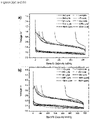
FIG. 2(a) shows the voltage-capacity curves of a porous Si/5 wt% PPy composite electrode according to an embodiment of the invention tested in a CCC mode of 420 mAh/g (10.0% lithiation) observed at 1st, 2nd, 3rd, 4th, 5th, 10th, 50th, 100th, 150th, 200th cycle. -
FIG. 2(b) shows the voltage-capacity curves of the same composite electrode tested in a CCC mode of 680 mAh/g (16.2% lithiation) observed at 1st, 2nd, 3rd, 4th, 5th, 10th, 50th, 100th, 150th, 200th cycle. -
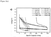
FIG. 2(c) shows the voltage-capacity curves of the same composite electrode tested in a CCC mode of 1000 mAh/g (23.8% lithiation) observed at 1st, 2nd, 3rd, 4th, 5th, 10th, 50th, 100th, 150th, 200th cycle. -
FIG. 3 shows the electrochemical impedance spectroscopy (EIS) of a porous Si/PPy composite electrode according to an embodiment of the invention tested in CCC mode of (a) 420 mAh/g (10.0% lithiation), (b) 680 mAh/g (16.2% lithiation) and (c) 1000 mAh/g (23.8% lithiation) at half lithiation of 10th, 20th, 30th, 40th, 50th, 100th, 150th, 200th cycle. -
FIG. 4 shows the electrochemical impedance spectroscopy (EIS) of Li/Li symmetrical coin cell of every ten cycles up to 150 cycles. - Unless defined otherwise, all technical and scientific terms used herein have the same meaning as commonly understood by one of ordinary skill in the art to which this invention belongs. Although any methods and materials similar or equivalent to those described herein can be used in the practice or testing of the present invention, the preferred methods and materials are now described.
- As used herein, "active material" means that portion of the electrode that stores lithium ions. In the case of the cathode, the active material can be a lithium-containing compound such as a lithium metal oxide complex. In the case of the counter, anode electrode the active material can be silicon or lithiated silicon.
- As used herein, "CCC mode" refers to constant-current charging which simply means that the charger supplies a relatively uniform current, regardless of the battery state of charge or temperature.
- Porous silicon structures (pSi) in general can intrinsically accommodate large volume expansions in composite electrodes, e.g., as used in lithium-ion batteries, better than spherical particles and/or other nanostructures. Porous silicon can have improved cycling behavior due to its high surface area and/or void volume, which can facilitate accommodation of volume changes, associated with lithiation and delithiation of the material. However, porous silicon also suffers from degradation effects, e.g., surface degradation and cracking, and in particular, over time the electrical contact between the active material particles may be lost. Researchers have found that introducing conductive carbon additives or coating layers onto porous silicon increases the electric contact at the beginning of the lifetime of the electrochemical cell. However, a large amount of the carbon additives will result in losing contact between the active materials and the non-sticky conductive carbon particles after a few cycles due to passivation layer formation on these particles. In addition, having a large amount of the carbon additives will decrease the amount of the active material in the cell and hence reduce the energy in the cell. The large carbonaceous surface area of the carbon additives also introduces more side reactions to the cell, ultimately lowering their reversibility, resulting in decreased columbic efficiency. In short, adding only the carbon additives to the electrode will not ultimately solve the life time issue of the porous silicon.
- Recently, as described in
U.S. Patent No. 9,153,353 - We provide a composite electrode comprising Si porous particles as an active material and a small amount of conductive polymer binder without the addition of carbon additives. The composite electrode prepared from porous Si and the conductive polymer binder was introduced as anode materials in lithium ion batteries. Here, the conductive polymer binder provides - besides a mechanical backbone - also a flexible network which additionally provides conductivity. The combination of the polymer binder's flexibility and conductivity and the ability of the pSi to absorb a significant portion of the volume expansion greatly extend the lifetime and also the columbic efficiency of the cell. We have found that by constantly charging the pSi anode incorporated with the conductive polymer binder at a limited capacity, a stable cycled cell with a greatly extended cycle life and high coulombic efficiency beyond 99.5%. We also found that both the morphology study and electrochemical characterization suggest that these electrodes are enabled to accommodate over 50% volume change without any capacity fading during cell operation.
- In one embodiment, a lithium ion battery is provided having a composite electrode comprising porous silicon with a specific capacity between 500 and 2200 mAh/g and a conductive polymer binder. In one embodiment, the porous silicon incorporates about 1 wt% up to 20 wt% of conductive polymer binder. In a preferred embodiment, the conductive polymer binder is present in an amount from about 5 wt% and up to 12 wt% of conductive polymer binder. Most preferably, it includes 5 wt% of conductive polymer binder. The conductive polymer binder is selected from the group consisting of a polymeric composition having repeating units of the formula:


U.S. Patent No. 9,153,353 - The porous silicon particles can range from micron to nano size. Typically, the porous silicon contains about 10 to 99 wt% of Si and about 1 to 90 wt% of C. In one embodiment, the porous silicon particles are preferably milled into a powdered form using any techniques known in the art, such as hand-milling, rotor-milling, ball-milling and jet-milling. In one embodiment, the porous silicon is present in the electrode in the amount of about 80 to 99 wt%. In another embodiment, about 0.5 to 5 wt% of conductive carbon is added to the electrode. In one embodiment, the porous Si has a calculated pore volume of 0.14 cm3/g and pore size of ~10 nm. In another embodiment, the porous silicon is comprised of a predominantly silicon core and has a volume ratio of silicon to void space of at least 1:1. In one embodiment, the porous silicon can be covered with a layer of carbonaceous materials to stabilize the outer surface towards the electrolyte. In another embodiment, the porous silicon can be deposited onto a conductive carrier material, i.e., carbon and/or copper. In another embodiment, the porous silicon deposited on a conductive carrier material is covered with an outer protective layer.
- In another embodiment, a method for making a composite electrode for use in a lithium ion battery is provided. The method comprises the steps of: forming a solution of a solvent and a conductive polymer binder; adding a porous silicon active material to the solution to form a slurry; mixing the slurry to form a homogeneous mixture; depositing a thin film of said thus obtained mixture over top of a substrate; and drying the resulting composite to form said electrode, wherein the conductive polymer binder is selected from the group consisting of a polymeric composition having repeating units of the formula:


- To examine the porous silicon's ability to accommodate volume change without any Si external swelling in the composite electrode of the invention, we partially lithiate the porous Si electrode to 10.0% , 16.2%, and 23.8% lithiation degree, corresponding to a specific capacity of 420, 680, and 1000 mAh/g, respectively. After controlling the lithiation to a desired level, we then delithiate Si up to the same cut-off voltage of 1 V. A lower lithiation cut-off voltage is set to 10 mV. Both discharge and charge are set to a constant current of 420 mA/g. With this constant charge capacity (CCC), we can evaluate how the porous Si accommodates different volume expansion from intercalating different amounts of lithium into Si. We have summarized the relationship among volume change, expected Si pore volume, lithiation degree and its corresponding specific capacity in Table 1 (shown below).
Table 1 Volume Change (%) Ideal internal pore volume (cm3/g) Lithiation Degree (%) Specific Capacity (mAh/g) 0 0 0 0 32 0.14 10.0 420 52 0.23 16.2 680 76 0.33 23.8 1000 320 1.4 100 4200 - Results of the various tests for the performance of porous Si/PPy composite electrode of various embodiments that were conducted are reported in the following plots of
FIGS. 1-4 . -
FIG. 1(a) shows electrode capacity as a function of cycle number for a porous Si/5 wt% PPy composite electrode according to one embodiment of the present invention with variable lithiation degrees. We partially lithiate the porous Si electrode to 10.0%, 16.2%, and 23.8% lithiation degree, which corresponds to a specific capacity of 420, 680 and 1000 mAh/g, respectively. It is clearly seen fromFIG. 1(a) that the composite electrode of the present invention provides a stable cycling performance in a CCC mode of 420 mAh/g (10.0% lithiation) and 680 mAh/g (16.2% lithiation). There is no capacity fading after 200 cycles upon 10.0% lithiation or 16.2% lithiation.FIG. 1(b) is a plot of coulombic efficiency (%) vs. cycle number for the same porous Si/5 wt% PPy composite electrode. As seen fromFIG. 1(b) , the first cycle coulombic efficiency is low due to solid electrolyte interface (SEI) layer formation and side reactions. After a few cycles, the coulombic efficiency quickly grows to 99.7% upon a 10% lithiation and to 99.4% upon a 16.2% lithiation. We found that even with an extra 6.2% lithiation at 16.2% as compared to 10% lithiation to the porous Si, the capacity still holds at 680 mAh/g without any fading. The consistent coulombic efficiency indicates that the porous silicon structure did not suffer from the SEI layer (re)formation. It is believed this may be either due to the mechanical strength of the active material itself or due to the flexible and conductive PPy polymer binder. However, the battery in a CCC mode of 1000 mAh/g eventually fails after 25 cycles with a loss in capacity. This might be caused by reaching a lithiation degree of the porous Si which no longer able to accommodate its volume expansion, leading to Si particle fracturing. - In
FIG. 1(c) , the lithiation end-voltage of each cycle is collected and plotted as function of cycle numbers. It can be seen that there is a clear impact to the electrode performance when applying different lithiation degrees. Particularly for the electrode in a CCC mode of 1000 mAh/g (23.8% lithiation), the porous Si anode can be charged to the expected capacity within the first 25 cycles before reaching the cut-off voltage of 10 mV. - In
FIG. 1(d) , the cycling performance of a porous Si/5 wt% PPy composite electrode according to an embodiment of the invention was compared to two other electrodes: non-conductive binder/porous Si electrode and conductive binder/non-porous Si electrode in a CCC mode of 420 mAh/g. For the composite electrode made with a micro-size Si particle (having a diameter of 1-5 µm) without any porous structure and 5 wt% PPy conductive binder in a CCC mode of 420 mAh/g, it was observed that after only a few cycles, the capacity of this electrode cannot even reach 250 mAh/g and declines to almost zero. This demonstrates indeed, that the porous Si plays a significant role in intrinsically accommodating the volume expansion derived from the alloying of lithium with silicon without irreversible structural damage. Under the same conditions, we investigated using a composite electrode made with a porous Si in combination with a commonly used non-conductive polymer binder carboxymethylcellulose (CMC) along with Super P carbon conducting additive. The fabricated Si half-cell exhibited reversible cycling but with a lower coulombic efficiency of about 99.3% after 200 cycles. Since a non-conductive binder always requires a certain amount of conductive carbon particles to provide electrical contact between active materials, this inevitably results in generating more side reactions and additional SEI layer formation and volumetric interference as the volume of the additive is not increasing at the same rate as the silicon. -
FIG. 2 shows voltage-capacity curves for a porous Si/5 wt% PPy composite electrode according to one embodiment of the invention at three fixed capacities tested in a CCC mode of (a) 420 mAh/g (10.0% lithiation), (b) 680 mAh/g (16.2% lithiation), and (c) 1000 mAh/g (23.8% lithiation) at 1st, 2nd, 3rd, 4th, 5th, 10th, 50th, 100th, 150th, and 200th cycle. When fixing the specific capacity to 420 mAh/g or 680 mAh/g (FIG. 2(a) and 2(b) ), the first five cycles complete with SEI formation as well as other side reactions, resulting in a coulombic efficiency below 95%. Starting from the 10th cycle, the cell exhibits a reversible cycling behavior and voltage-capacity curves overlap perfectly with each other. Seen inFIG. 2(c) , when fixing the specific capacity to 1000 mAh/g, the voltage-capacity curve shows a similar behavior as 420 mAh/g and 680 mAh/g. But since a capacity decline was observed in the 25th cycle (SeeFIG. 1(a) ), the capacity from the 50th cycle to the 200th cycle continues to decline. -
FIG. 3 provides the impedance measurements of porous Si/ PPy binder composite electrode according to one embodiment of the invention at different cycles up to 200 cycles.FIG. 4 provides the EIS of Li/Li symmetrical coin cell of every ten cycles up to 150 cycles. ComparingFIG. 3 withFIG. 4 , we found that the impedance actually comes from contribution both of Si electrode and Li electrode. For a given 420 mAh/g (10.0%) and 680 mAh/g (16.2%) lithiation, it seems that there are no obvious changes on impedance response, which demonstrates a limited SEI layer growth. However, with a constant 1000 mAh/g (23.8%) lithiation, a visible and continuous resistance increase could be observed, indicating a SEI layer growth. - Based on the various tests we conducted, it has been shown that the combination of the porous silicon structure with a small amount of conductive polymer binder allows us to overcome the intrinsic problem of silicon particle degradation during prolonged cycling. The composite electrodes of the invention manufactured with this composition outperformed laminates using "standard" non-porous silicon and laminates using porous Si, a "non-conductive" commercially available convention binder, and conductive additives. We found that the composite electrode of the invention enabled to accommodate a volume change up to 52 % corresponding to a constant capacity cycling of 420 or 680 mAh/g, with no capacity fading after 200 cycles at a cycling rate 1C.
- It should be recognized that the one or more examples in the disclosure are nonlimiting examples and that the present invention is intended to encompass variations and equivalents of these examples.
- Electrode Compositions: All electrode laminates are made of conductive polymer binder and silicon active material. Porous Si is commercially available and can be obtained from VestaSi and other sources. Micro-size non-porous Si is commercially available and can be obtained from Alfa Aesar. Pyrene-based conductive binders were synthesized as described in
U.S. Patent No. 9,153,353 - Chemicals: All the starting chemical materials for the synthesis of the conductive polymer were purchased from Sigma-Aldrich. Electrolytes were purchased from Novolyte Technologies (now part of BASF), including battery-grade lithium hexafluorophosphate (LiPF6) in ethylene carbonate (EC), diethyl carbonate (DEC) and fluoroethylene carbonate (FEC). A Celgard 3501 separator membrane was purchased from Celgard. Other chemicals were purchased from Sigma Aldrich and used without any further purification.
- All electrode laminates were cast onto a 20 µm thick battery-grade Cu sheet using a Mitutoyo doctor blade and a Yoshimitsu Seiki vacuum drawdown coater to roughly the same loading per unit area of active material. The films and laminates were first dried under infrared lamps for 1 h until most of the solvent was evaporated and they appeared dried. The films and laminates were further dried at 130° C under 10-2 torr dynamic vacuum for 24 h. The film and laminate thicknesses were measured with a Mitutoyo micrometer with an accuracy of ±1 µm. Several loadings and thicknesses up to 4.8 mAh/com2 were done and the electrodes were also pressed and un-pressed using a calender machine from International Rolling Mill equipped with a continuously adjustable gap.
- Coin cell assembly was performed using standard 2325 coin cell hardware. A 1.47 cm diameter disk was punched out from the laminate for use in the coin cell assembly as a working electrode. Lithium foil (obtained from FMC Corporation) was used in making the counter electrode. The counter electrodes were cut to 1.5 cm diameter disks. The working electrode was placed in the center of the outer shell of the coin cell assembly and two drops of 30% FEC, 1.2 M LiPF6 in EC/DEC =3/7 electrolyte purchased from BASF were added to wet the electrode. A 2 cm diameter of Celgard 2400 porous polyethylene separator was placed on top of the working electrode. Three more drops of the electrolyte were added to the separator. The counter electrode was placed on the top of the separator. Special care was taken to align the counter electrode symmetrically above the working electrode. A stainless steel spacer and a Belleville spring were placed on top of the counter electrode. A plastic grommet was placed on top of the outer edge of the electrode assembly and crimp closed with a custom-built crimping machine manufactured by National Research Council of Canada. The entire cell fabrication procedure was done in an Ar-atmosphere glove box.
- The coin cell performance was evaluated in a thermal chamber at 30° C with a Maccor Series 4000 Battery Test System. In a constant charge capacity cycling, the coin cells were first lithiated to a certain degree corresponding to a calculated specific capacity, then delithiated back to IV. A lower cut-off voltage was set to 10 mV. The electrochemical impedance spectrum (EIS) tests were performed at 50% depth of lithiation at frequencies between 3 x 10⁴ Hz and 0.01 Hz using a Solartron 1260 impedance/gain-phase analyzer coupled with Maccor battery test system. The capacity of the material was calculated on the bases of the theoretical capacity and the amount of the materials used within the electrode.
Claims (2)
- A composite electrode for use in a lithium-ion battery comprising a porous silicon with a specific capacity between 500 and 2200 mAh/g and a conductive polymer binder, wherein the conductive polymer binder is selected from the group consisting of a polymeric composition having repeating units of the formula:wherein n=1-10 million,
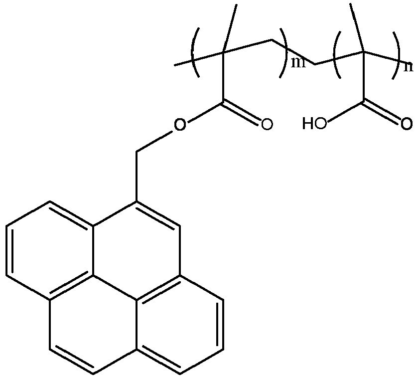
 wherein the porous silicon is deposited onto a conductive carrier material and coated with a protective layer, and wherein the porous silicon has a volume ratio of silicon to void space of 1:1.
 - A method for making a composite electrode of claim 1 for use in a lithium ion battery comprising the steps of:forming a solution of a solvent and a conductive polymer binder;adding a porous silicon active material to the solution to form a slurry; mixing the slurry to form a homogeneous mixture;depositing a thin film of said thus obtained mixture over top of a substrate; and drying the resulting composite to form said electrode,wherein the porous silicon is deposited onto a conductive carrier material and coated with a protective layer, and wherein the porous silicon has a volume ratio of silicon to void space of 1:1.
Applications Claiming Priority (2)
| Application Number | Priority Date | Filing Date | Title |
|---|---|---|---|
| US15/260,421 US20180076458A1 (en) | 2016-09-09 | 2016-09-09 | Porous Silicon Materials and Conductive Polymer Binder Electrodes |
| PCT/EP2017/071864 WO2018046385A1 (en) | 2016-09-09 | 2017-08-31 | Porous silicon materials and conductive polymer binder electrodes |
Publications (2)
| Publication Number | Publication Date |
|---|---|
| EP3510654A1 EP3510654A1 (en) | 2019-07-17 |
| EP3510654B1 true EP3510654B1 (en) | 2022-08-17 |
Family
ID=59745295
Family Applications (1)
| Application Number | Title | Priority Date | Filing Date |
|---|---|---|---|
| EP17758876.1A Active EP3510654B1 (en) | 2016-09-09 | 2017-08-31 | Porous silicon materials and conductive polymer binder electrodes |
Country Status (6)
| Country | Link |
|---|---|
| US (1) | US20180076458A1 (en) |
| EP (1) | EP3510654B1 (en) |
| JP (1) | JP7193449B2 (en) |
| KR (2) | KR102732230B1 (en) |
| CN (1) | CN109819685A (en) |
| WO (1) | WO2018046385A1 (en) |
Families Citing this family (9)
| Publication number | Priority date | Publication date | Assignee | Title |
|---|---|---|---|---|
| US10930933B2 (en) | 2016-09-09 | 2021-02-23 | Bayerische Motoren Werke Aktiengesellschaft | Conductive polymer binder for a novel silicon/graphene anode in lithium ion batteries |
| US10403897B2 (en) | 2017-05-19 | 2019-09-03 | Bayerische Motoren Werke Aktiengesellschaft | Conductive polymer binder for a novel silicon/graphene anode in lithium ion batteries |
| CN109148886B (en) * | 2018-08-28 | 2021-06-11 | 合肥国轩高科动力能源有限公司 | Binder, preparation method thereof and lithium ion battery negative plate |
| US11205778B2 (en) | 2019-06-12 | 2021-12-21 | The Regents Of The University Of California | Conductive polymer emulsion |
| US20210313617A1 (en) * | 2020-04-03 | 2021-10-07 | Sila Nanotechnologies Inc. | Lithium-ion battery with anode comprising blend of intercalation-type anode material and conversion-type anode material |
| CN111769285B (en) * | 2020-07-01 | 2022-04-01 | 苏州凌威新能源科技有限公司 | Lithium battery negative electrode adhesive and negative electrode plate |
| CN118043994A (en) * | 2021-07-20 | 2024-05-14 | 松下控股株式会社 | Negative electrode active material and battery |
| JP7789784B2 (en) * | 2021-07-20 | 2025-12-22 | パナソニックホールディングス株式会社 | Negative electrode active material and battery |
| CN115588742A (en) * | 2022-11-04 | 2023-01-10 | 合肥国轩高科动力能源有限公司 | Composite binder applied to lithium ion battery silicon-carbon cathode system and cathode material containing same |
Family Cites Families (15)
| Publication number | Priority date | Publication date | Assignee | Title |
|---|---|---|---|---|
| US8435676B2 (en) * | 2008-01-09 | 2013-05-07 | Nanotek Instruments, Inc. | Mixed nano-filament electrode materials for lithium ion batteries |
| US8187752B2 (en) * | 2008-04-16 | 2012-05-29 | Envia Systems, Inc. | High energy lithium ion secondary batteries |
| US9153353B2 (en) * | 2009-05-18 | 2015-10-06 | The Regents Of The University Of California | Electronically conductive polymer binder for lithium-ion battery electrode |
| US20150028022A1 (en) * | 2009-07-21 | 2015-01-29 | Nuwave LLC | Induction cooktop |
| US20120231326A1 (en) * | 2009-10-30 | 2012-09-13 | Lockheed Martin Corporation | Structured silicon battery anodes |
| EP2360772A1 (en) * | 2010-02-12 | 2011-08-24 | Fortu Intellectual Property AG | Rechargeable and electrochemical cell |
| CN102214817A (en) * | 2010-04-09 | 2011-10-12 | 清华大学 | Carbon/silicon/carbon nano composite structure cathode material and preparation method thereof |
| US9214668B2 (en) * | 2010-06-02 | 2015-12-15 | The Regents Of The University Of California | Si composite electrode with Li metal doping for advanced lithium-ion battery |
| US10079389B2 (en) * | 2012-05-18 | 2018-09-18 | Xg Sciences, Inc. | Silicon-graphene nanocomposites for electrochemical applications |
| CN102800851A (en) * | 2012-08-17 | 2012-11-28 | 奇瑞汽车股份有限公司 | Silicon carbon composite material and preparation method thereof, lithium ion battery containing same |
| US9985286B2 (en) * | 2012-11-13 | 2018-05-29 | Nec Corporation | Negative electrode active material, method for manufacturing same, and lithium secondary battery |
| JP6407727B2 (en) * | 2013-01-29 | 2018-10-17 | 三洋電機株式会社 | Negative electrode active material for nonaqueous electrolyte secondary battery, negative electrode for nonaqueous electrolyte secondary battery using the negative electrode active material, and nonaqueous electrolyte secondary battery using the negative electrode |
| EP2873646B1 (en) * | 2013-09-02 | 2019-04-03 | LG Chem, Ltd. | Porous silicon based particles, method for preparing same and anode active material comprising same |
| KR101724196B1 (en) * | 2014-05-09 | 2017-04-06 | 주식회사 엘지화학 | Graphene-wrapped porous silicon-carbon composite and preparation method thereof |
| JP2016072286A (en) * | 2014-09-26 | 2016-05-09 | 京セラ株式会社 | Nanocomposite material and nanocomposite material dispersion solution, and photoelectric conversion device |
-
2016
- 2016-09-09 US US15/260,421 patent/US20180076458A1/en not_active Abandoned
-
2017
- 2017-08-31 JP JP2019513353A patent/JP7193449B2/en active Active
- 2017-08-31 WO PCT/EP2017/071864 patent/WO2018046385A1/en not_active Ceased
- 2017-08-31 EP EP17758876.1A patent/EP3510654B1/en active Active
- 2017-08-31 CN CN201780055173.5A patent/CN109819685A/en active Pending
- 2017-09-22 KR KR1020237019581A patent/KR102732230B1/en active Active
- 2017-09-22 KR KR1020197008659A patent/KR20190077319A/en not_active Ceased
Also Published As
| Publication number | Publication date |
|---|---|
| KR102732230B1 (en) | 2024-11-19 |
| EP3510654A1 (en) | 2019-07-17 |
| WO2018046385A1 (en) | 2018-03-15 |
| US20180076458A1 (en) | 2018-03-15 |
| KR20230090374A (en) | 2023-06-21 |
| JP2019526915A (en) | 2019-09-19 |
| KR20190077319A (en) | 2019-07-03 |
| JP7193449B2 (en) | 2022-12-20 |
| CN109819685A (en) | 2019-05-28 |
Similar Documents
| Publication | Publication Date | Title |
|---|---|---|
| EP3510654B1 (en) | Porous silicon materials and conductive polymer binder electrodes | |
| Lin et al. | Chemical doping of a core–shell silicon nanoparticles@ polyaniline nanocomposite for the performance enhancement of a lithium ion battery anode | |
| US9444090B2 (en) | Lithium metal doped electrodes for lithium-ion rechargeable chemistry | |
| EP2605325B1 (en) | Cathode current collector coated with a primer and magnesium secondary battery including same | |
| US20230127888A1 (en) | Secondary battery with improved high-temperature and low-temperature properties | |
| CN113809283A (en) | Negative electrode for lithium secondary battery and lithium secondary battery comprising same | |
| Kim et al. | High rate lithium ion battery with niobium tungsten oxide anode | |
| EP3846257B1 (en) | Negative electrode active material for lithium secondary battery, and negative electrode and lithium secondary battery including the same | |
| CN109449447A (en) | Secondary battery | |
| CN109449373A (en) | Negative pole piece and battery | |
| KR102405902B1 (en) | Negavive electrode for lithium secondary battery, and lithium secondary battery comprising the same | |
| KR102419750B1 (en) | Conductive polymer binder for novel silicon/graphene anodes in lithium-ion batteries | |
| EP3534436B1 (en) | Negative electrode, secondary battery including same negative electrode, and method for manufacturing same negative electrode | |
| CN102593455A (en) | Negative active material composition, method of preparing negative electrode plate and lithium secondary battery by using the same | |
| US20240332542A1 (en) | Carbon fiber-carbon nanotube-polymer based composite current collector | |
| KR102640199B1 (en) | Lithium secondary battery | |
| KR20170034212A (en) | Composite anode active material, lithium battery including the same, and method of preparing the composite anode active material | |
| US10403897B2 (en) | Conductive polymer binder for a novel silicon/graphene anode in lithium ion batteries | |
| Zhang et al. | Revisiting Polytetrafluorethylene Binder for Solvent-Free Lithium-Ion Battery Anode Fabrication. Batteries 2022, 8, 57 | |
| TW202348559A (en) | Core-shell nanoparticles and methods of fabrication thereof | |
| O'Meara | Development of Ni (CH3-Salen) Conductive Polymer for use in Li-ion Cathodes |
Legal Events
| Date | Code | Title | Description |
|---|---|---|---|
| STAA | Information on the status of an ep patent application or granted ep patent |
Free format text: STATUS: UNKNOWN |
|
| STAA | Information on the status of an ep patent application or granted ep patent |
Free format text: STATUS: THE INTERNATIONAL PUBLICATION HAS BEEN MADE |
|
| PUAI | Public reference made under article 153(3) epc to a published international application that has entered the european phase |
Free format text: ORIGINAL CODE: 0009012 |
|
| STAA | Information on the status of an ep patent application or granted ep patent |
Free format text: STATUS: REQUEST FOR EXAMINATION WAS MADE |
|
| 17P | Request for examination filed |
Effective date: 20190404 |
|
| AK | Designated contracting states |
Kind code of ref document: A1 Designated state(s): AL AT BE BG CH CY CZ DE DK EE ES FI FR GB GR HR HU IE IS IT LI LT LU LV MC MK MT NL NO PL PT RO RS SE SI SK SM TR |
|
| AX | Request for extension of the european patent |
Extension state: BA ME |
|
| DAV | Request for validation of the european patent (deleted) | ||
| DAX | Request for extension of the european patent (deleted) | ||
| RIN1 | Information on inventor provided before grant (corrected) |
Inventor name: LANGER, THORSTEN Inventor name: GAO, LIU Inventor name: WEN, YUAN Inventor name: LUX, SIMON Inventor name: GENTSCHEV, ANN-CHRISTIN |
|
| STAA | Information on the status of an ep patent application or granted ep patent |
Free format text: STATUS: EXAMINATION IS IN PROGRESS |
|
| 17Q | First examination report despatched |
Effective date: 20210622 |
|
| GRAP | Despatch of communication of intention to grant a patent |
Free format text: ORIGINAL CODE: EPIDOSNIGR1 |
|
| STAA | Information on the status of an ep patent application or granted ep patent |
Free format text: STATUS: GRANT OF PATENT IS INTENDED |
|
| INTG | Intention to grant announced |
Effective date: 20220407 |
|
| GRAS | Grant fee paid |
Free format text: ORIGINAL CODE: EPIDOSNIGR3 |
|
| GRAA | (expected) grant |
Free format text: ORIGINAL CODE: 0009210 |
|
| STAA | Information on the status of an ep patent application or granted ep patent |
Free format text: STATUS: THE PATENT HAS BEEN GRANTED |
|
| AK | Designated contracting states |
Kind code of ref document: B1 Designated state(s): AL AT BE BG CH CY CZ DE DK EE ES FI FR GB GR HR HU IE IS IT LI LT LU LV MC MK MT NL NO PL PT RO RS SE SI SK SM TR |
|
| REG | Reference to a national code |
Ref country code: CH Ref legal event code: EP |
|
| REG | Reference to a national code |
Ref country code: DE Ref legal event code: R096 Ref document number: 602017060762 Country of ref document: DE |
|
| REG | Reference to a national code |
Ref country code: IE Ref legal event code: FG4D |
|
| REG | Reference to a national code |
Ref country code: AT Ref legal event code: REF Ref document number: 1512753 Country of ref document: AT Kind code of ref document: T Effective date: 20220915 |
|
| REG | Reference to a national code |
Ref country code: SE Ref legal event code: TRGR |
|
| REG | Reference to a national code |
Ref country code: NL Ref legal event code: MP Effective date: 20220817 |
|
| REG | Reference to a national code |
Ref country code: LT Ref legal event code: MG9D |
|
| PG25 | Lapsed in a contracting state [announced via postgrant information from national office to epo] |
Ref country code: RS Free format text: LAPSE BECAUSE OF FAILURE TO SUBMIT A TRANSLATION OF THE DESCRIPTION OR TO PAY THE FEE WITHIN THE PRESCRIBED TIME-LIMIT Effective date: 20220817 Ref country code: PT Free format text: LAPSE BECAUSE OF FAILURE TO SUBMIT A TRANSLATION OF THE DESCRIPTION OR TO PAY THE FEE WITHIN THE PRESCRIBED TIME-LIMIT Effective date: 20221219 Ref country code: NO Free format text: LAPSE BECAUSE OF FAILURE TO SUBMIT A TRANSLATION OF THE DESCRIPTION OR TO PAY THE FEE WITHIN THE PRESCRIBED TIME-LIMIT Effective date: 20221117 Ref country code: NL Free format text: LAPSE BECAUSE OF FAILURE TO SUBMIT A TRANSLATION OF THE DESCRIPTION OR TO PAY THE FEE WITHIN THE PRESCRIBED TIME-LIMIT Effective date: 20220817 Ref country code: LV Free format text: LAPSE BECAUSE OF FAILURE TO SUBMIT A TRANSLATION OF THE DESCRIPTION OR TO PAY THE FEE WITHIN THE PRESCRIBED TIME-LIMIT Effective date: 20220817 Ref country code: LT Free format text: LAPSE BECAUSE OF FAILURE TO SUBMIT A TRANSLATION OF THE DESCRIPTION OR TO PAY THE FEE WITHIN THE PRESCRIBED TIME-LIMIT Effective date: 20220817 Ref country code: FI Free format text: LAPSE BECAUSE OF FAILURE TO SUBMIT A TRANSLATION OF THE DESCRIPTION OR TO PAY THE FEE WITHIN THE PRESCRIBED TIME-LIMIT Effective date: 20220817 |
|
| REG | Reference to a national code |
Ref country code: AT Ref legal event code: MK05 Ref document number: 1512753 Country of ref document: AT Kind code of ref document: T Effective date: 20220817 |
|
| PG25 | Lapsed in a contracting state [announced via postgrant information from national office to epo] |
Ref country code: PL Free format text: LAPSE BECAUSE OF FAILURE TO SUBMIT A TRANSLATION OF THE DESCRIPTION OR TO PAY THE FEE WITHIN THE PRESCRIBED TIME-LIMIT Effective date: 20220817 Ref country code: IS Free format text: LAPSE BECAUSE OF FAILURE TO SUBMIT A TRANSLATION OF THE DESCRIPTION OR TO PAY THE FEE WITHIN THE PRESCRIBED TIME-LIMIT Effective date: 20221217 Ref country code: HR Free format text: LAPSE BECAUSE OF FAILURE TO SUBMIT A TRANSLATION OF THE DESCRIPTION OR TO PAY THE FEE WITHIN THE PRESCRIBED TIME-LIMIT Effective date: 20220817 Ref country code: GR Free format text: LAPSE BECAUSE OF FAILURE TO SUBMIT A TRANSLATION OF THE DESCRIPTION OR TO PAY THE FEE WITHIN THE PRESCRIBED TIME-LIMIT Effective date: 20221118 |
|
| REG | Reference to a national code |
Ref country code: CH Ref legal event code: PL |
|
| PG25 | Lapsed in a contracting state [announced via postgrant information from national office to epo] |
Ref country code: SM Free format text: LAPSE BECAUSE OF FAILURE TO SUBMIT A TRANSLATION OF THE DESCRIPTION OR TO PAY THE FEE WITHIN THE PRESCRIBED TIME-LIMIT Effective date: 20220817 Ref country code: RO Free format text: LAPSE BECAUSE OF FAILURE TO SUBMIT A TRANSLATION OF THE DESCRIPTION OR TO PAY THE FEE WITHIN THE PRESCRIBED TIME-LIMIT Effective date: 20220817 Ref country code: LU Free format text: LAPSE BECAUSE OF NON-PAYMENT OF DUE FEES Effective date: 20220831 Ref country code: LI Free format text: LAPSE BECAUSE OF NON-PAYMENT OF DUE FEES Effective date: 20220831 Ref country code: ES Free format text: LAPSE BECAUSE OF FAILURE TO SUBMIT A TRANSLATION OF THE DESCRIPTION OR TO PAY THE FEE WITHIN THE PRESCRIBED TIME-LIMIT Effective date: 20220817 Ref country code: DK Free format text: LAPSE BECAUSE OF FAILURE TO SUBMIT A TRANSLATION OF THE DESCRIPTION OR TO PAY THE FEE WITHIN THE PRESCRIBED TIME-LIMIT Effective date: 20220817 Ref country code: CZ Free format text: LAPSE BECAUSE OF FAILURE TO SUBMIT A TRANSLATION OF THE DESCRIPTION OR TO PAY THE FEE WITHIN THE PRESCRIBED TIME-LIMIT Effective date: 20220817 Ref country code: CH Free format text: LAPSE BECAUSE OF NON-PAYMENT OF DUE FEES Effective date: 20220831 Ref country code: AT Free format text: LAPSE BECAUSE OF FAILURE TO SUBMIT A TRANSLATION OF THE DESCRIPTION OR TO PAY THE FEE WITHIN THE PRESCRIBED TIME-LIMIT Effective date: 20220817 |
|
| REG | Reference to a national code |
Ref country code: BE Ref legal event code: MM Effective date: 20220831 |
|
| REG | Reference to a national code |
Ref country code: DE Ref legal event code: R097 Ref document number: 602017060762 Country of ref document: DE |
|
| PG25 | Lapsed in a contracting state [announced via postgrant information from national office to epo] |
Ref country code: SK Free format text: LAPSE BECAUSE OF FAILURE TO SUBMIT A TRANSLATION OF THE DESCRIPTION OR TO PAY THE FEE WITHIN THE PRESCRIBED TIME-LIMIT Effective date: 20220817 Ref country code: MC Free format text: LAPSE BECAUSE OF FAILURE TO SUBMIT A TRANSLATION OF THE DESCRIPTION OR TO PAY THE FEE WITHIN THE PRESCRIBED TIME-LIMIT Effective date: 20220817 Ref country code: EE Free format text: LAPSE BECAUSE OF FAILURE TO SUBMIT A TRANSLATION OF THE DESCRIPTION OR TO PAY THE FEE WITHIN THE PRESCRIBED TIME-LIMIT Effective date: 20220817 |
|
| P01 | Opt-out of the competence of the unified patent court (upc) registered |
Effective date: 20230427 |
|
| PLBE | No opposition filed within time limit |
Free format text: ORIGINAL CODE: 0009261 |
|
| STAA | Information on the status of an ep patent application or granted ep patent |
Free format text: STATUS: NO OPPOSITION FILED WITHIN TIME LIMIT |
|
| PG25 | Lapsed in a contracting state [announced via postgrant information from national office to epo] |
Ref country code: AL Free format text: LAPSE BECAUSE OF FAILURE TO SUBMIT A TRANSLATION OF THE DESCRIPTION OR TO PAY THE FEE WITHIN THE PRESCRIBED TIME-LIMIT Effective date: 20220817 |
|
| 26N | No opposition filed |
Effective date: 20230519 |
|
| PG25 | Lapsed in a contracting state [announced via postgrant information from national office to epo] |
Ref country code: IE Free format text: LAPSE BECAUSE OF NON-PAYMENT OF DUE FEES Effective date: 20220831 |
|
| PG25 | Lapsed in a contracting state [announced via postgrant information from national office to epo] |
Ref country code: SI Free format text: LAPSE BECAUSE OF FAILURE TO SUBMIT A TRANSLATION OF THE DESCRIPTION OR TO PAY THE FEE WITHIN THE PRESCRIBED TIME-LIMIT Effective date: 20220817 |
|
| PG25 | Lapsed in a contracting state [announced via postgrant information from national office to epo] |
Ref country code: BE Free format text: LAPSE BECAUSE OF NON-PAYMENT OF DUE FEES Effective date: 20220831 |
|
| PG25 | Lapsed in a contracting state [announced via postgrant information from national office to epo] |
Ref country code: HU Free format text: LAPSE BECAUSE OF FAILURE TO SUBMIT A TRANSLATION OF THE DESCRIPTION OR TO PAY THE FEE WITHIN THE PRESCRIBED TIME-LIMIT; INVALID AB INITIO Effective date: 20170831 |
|
| PG25 | Lapsed in a contracting state [announced via postgrant information from national office to epo] |
Ref country code: CY Free format text: LAPSE BECAUSE OF FAILURE TO SUBMIT A TRANSLATION OF THE DESCRIPTION OR TO PAY THE FEE WITHIN THE PRESCRIBED TIME-LIMIT Effective date: 20220817 |
|
| PG25 | Lapsed in a contracting state [announced via postgrant information from national office to epo] |
Ref country code: MK Free format text: LAPSE BECAUSE OF FAILURE TO SUBMIT A TRANSLATION OF THE DESCRIPTION OR TO PAY THE FEE WITHIN THE PRESCRIBED TIME-LIMIT Effective date: 20220817 |
|
| PG25 | Lapsed in a contracting state [announced via postgrant information from national office to epo] |
Ref country code: BG Free format text: LAPSE BECAUSE OF FAILURE TO SUBMIT A TRANSLATION OF THE DESCRIPTION OR TO PAY THE FEE WITHIN THE PRESCRIBED TIME-LIMIT Effective date: 20220817 |
|
| PG25 | Lapsed in a contracting state [announced via postgrant information from national office to epo] |
Ref country code: MT Free format text: LAPSE BECAUSE OF FAILURE TO SUBMIT A TRANSLATION OF THE DESCRIPTION OR TO PAY THE FEE WITHIN THE PRESCRIBED TIME-LIMIT Effective date: 20220817 |
|
| PGFP | Annual fee paid to national office [announced via postgrant information from national office to epo] |
Ref country code: DE Payment date: 20250731 Year of fee payment: 9 |
|
| PGFP | Annual fee paid to national office [announced via postgrant information from national office to epo] |
Ref country code: IT Payment date: 20250829 Year of fee payment: 9 |
|
| PGFP | Annual fee paid to national office [announced via postgrant information from national office to epo] |
Ref country code: GB Payment date: 20250822 Year of fee payment: 9 |
|
| PGFP | Annual fee paid to national office [announced via postgrant information from national office to epo] |
Ref country code: FR Payment date: 20250821 Year of fee payment: 9 |
|
| PGFP | Annual fee paid to national office [announced via postgrant information from national office to epo] |
Ref country code: SE Payment date: 20250821 Year of fee payment: 9 |
|
| PG25 | Lapsed in a contracting state [announced via postgrant information from national office to epo] |
Ref country code: TR Free format text: LAPSE BECAUSE OF FAILURE TO SUBMIT A TRANSLATION OF THE DESCRIPTION OR TO PAY THE FEE WITHIN THE PRESCRIBED TIME-LIMIT Effective date: 20220817 |