EP3510613B1 - A cover for a distribution transformer filled with a dielectric liquid - Google Patents
A cover for a distribution transformer filled with a dielectric liquid Download PDFInfo
- Publication number
- EP3510613B1 EP3510613B1 EP17755061.3A EP17755061A EP3510613B1 EP 3510613 B1 EP3510613 B1 EP 3510613B1 EP 17755061 A EP17755061 A EP 17755061A EP 3510613 B1 EP3510613 B1 EP 3510613B1
- Authority
- EP
- European Patent Office
- Prior art keywords
- cooling compartment
- cover
- bottom wall
- distribution transformer
- oil
- Prior art date
- Legal status (The legal status is an assumption and is not a legal conclusion. Google has not performed a legal analysis and makes no representation as to the accuracy of the status listed.)
- Active
Links
Images


Classifications
-
- H—ELECTRICITY
- H01—ELECTRIC ELEMENTS
- H01F—MAGNETS; INDUCTANCES; TRANSFORMERS; SELECTION OF MATERIALS FOR THEIR MAGNETIC PROPERTIES
- H01F27/00—Details of transformers or inductances, in general
- H01F27/08—Cooling; Ventilating
- H01F27/10—Liquid cooling
- H01F27/12—Oil cooling
-
- H—ELECTRICITY
- H01—ELECTRIC ELEMENTS
- H01F—MAGNETS; INDUCTANCES; TRANSFORMERS; SELECTION OF MATERIALS FOR THEIR MAGNETIC PROPERTIES
- H01F27/00—Details of transformers or inductances, in general
- H01F27/02—Casings
- H01F27/025—Constructional details relating to cooling
-
- H—ELECTRICITY
- H01—ELECTRIC ELEMENTS
- H01F—MAGNETS; INDUCTANCES; TRANSFORMERS; SELECTION OF MATERIALS FOR THEIR MAGNETIC PROPERTIES
- H01F27/00—Details of transformers or inductances, in general
- H01F27/02—Casings
- H01F27/04—Leading of conductors or axles through casings, e.g. for tap-changing arrangements
-
- H—ELECTRICITY
- H01—ELECTRIC ELEMENTS
- H01F—MAGNETS; INDUCTANCES; TRANSFORMERS; SELECTION OF MATERIALS FOR THEIR MAGNETIC PROPERTIES
- H01F27/00—Details of transformers or inductances, in general
- H01F27/40—Structural association with built-in electric component, e.g. fuse
- H01F27/402—Association of measuring or protective means
-
- H—ELECTRICITY
- H01—ELECTRIC ELEMENTS
- H01F—MAGNETS; INDUCTANCES; TRANSFORMERS; SELECTION OF MATERIALS FOR THEIR MAGNETIC PROPERTIES
- H01F27/00—Details of transformers or inductances, in general
- H01F27/40—Structural association with built-in electric component, e.g. fuse
- H01F27/402—Association of measuring or protective means
- H01F2027/404—Protective devices specially adapted for fluid filled transformers
-
- H—ELECTRICITY
- H01—ELECTRIC ELEMENTS
- H01F—MAGNETS; INDUCTANCES; TRANSFORMERS; SELECTION OF MATERIALS FOR THEIR MAGNETIC PROPERTIES
- H01F27/00—Details of transformers or inductances, in general
- H01F27/08—Cooling; Ventilating
- H01F27/10—Liquid cooling
- H01F27/12—Oil cooling
- H01F27/14—Expansion chambers; Oil conservators; Gas cushions; Arrangements for purifying, drying, or filling
Definitions
- the subject of the invention is a cover for a distribution transformer filled with a dielectric liquid, equipped with electronic means integrated with the cover which is applied for transmission and distribution of electric energy.
- An electrical lead through connector for connecting MV or HV conductor with a load placed in a tank containing a dielectric liquid or dielectric gas.
- An electrical lead through connector comprises a plug-in bushing member made of insulating material, where a series filtering choke is embedded.
- the filtering choke has a first terminal which is electrically connected with an external HV or MV line and has a second terminal which is connected to a load placed inside the tank.
- the lead through connector is further provided with an additional bushing member which is mechanically connected with the plug-in bushing member through a common insulating base.
- the additional bushing member is equipped with a conductor located inside the bushing member, where the conductor is directly connected with the second terminal of the filtering choke and with an external protective component against electrical surges.
- the regulating transformer is a local mains transformer or a consumer-proximal distribution transformer.
- the regulating transformer comprises an oil-filed vessel in which at least one yoke and windings of the regulating transformer are disposed.
- the tap-changer comprises a mechanical contact system for selection of a tap of regulating winding of the regulating transformer as well as a load changeover switch for actual on-load switching.
- the mechanical contact system of the tap changer is in the vessel below the transformer cover and above the yoke.
- the load changeover switch is outside the vessel above the transformer cover and comprises thyristors or IGBTs.
- the load changeover switch and mechanical contact system of the tap changer are separated from one another by a horizontal insulation lead -trough plate. So the electronic components can be operated in air and the mechanical contact system can be operated in oil.
- This solution presents the electronic equipment situated external to the tank and having electrical connections with the load placed inside the tank but the solution said nothing about the electronic devices which are immersed in the oil together with the mechanical systems.
- This solution said nothing about the cooling of the electronic devices in the oil having lower critical level of working temperature than temperature the oil inside the tank of the transformer.
- An essence of the invention is a cover for covering a distribution transformer with a main tank filled with a dielectric liquid in which an active part of the distribution transformer is placed, the cover has a cooling compartment to be filled with dielectric liquid located at an upper part of the cover and at least one electronic device for electrical connection with the active part of the distribution transformer, wherein the cooling compartment has bottom wall, side walls and a top wall, said electronic device is placed inside the cooling compartment, said bottom wall is adapted to form a thermal barrier between the interior of a main tank of the distribution transformer and adapted so that the interior of the cooling compartment and the both interiors of the cooling compartment and of the main tank are hermetically closed together when filled with the dielectric liquid characterized in that the cover is equipped with a window in which a bottom wall of the cooling compartment is inserted and matched by a chamfer disposed on the entirely circumference of the bottom wall.
- the thermal barrier is made from a high thermal resistive material having a coefficient of the thermal conductivity not higher than 0,24 W/(m ⁇ K).
- the bottom wall of the cooling compartment is provided with at least one through hole for insertion in it a conductor for electrical connection of the electronic device with the active part of the distribution transformer.
- the cover comprises an oil filling pipe and a protection device for measuring of a level of the dielectric liquid inside the cooling compartment wherein the protection device is connected with an oil filling pipe and with the cooling compartment via a flexible pipe.
- At least one side wall of the cooling compartment is equipped with external ribs.
- the top wall of the cooling compartment is equipped with external ribs.
- the electronic device is a tap-changer placed in the cooling compartment.
- the electronic device is connected with at least one conductor for electrical connection of the electronic device with the active part of the distribution transformer, the at least one conductor being inserted in at least one of the through holes provided in the bottom wall of the cooling compartment.
- the cover according to the invention enables to integrate thermal sensitive devices like electronic or power electronic device with oil immersed power products like distribution transformer without need of hermetically insulation of separate compartments with dielectric liquids.
- Such arrangement of separate oil volume compartments is less costly and less difficult to applicate on the electric power device than expensive connection of two totally separated and sealed fluid volumes connected by the expensive MV bushings and MV power cables.
- the invention removes the problems with sealing compartments and the problems with the insulation of leads of the conductors provided from electronic device to the active part of the power product such as transformer. In proposed solution the time consuming processes of carried out the special insulation of the leads and bushing joints can be omitted.
- Using the thermal barrier as a common part of the cover and the cooling compartment allows for differentiation the temperature of the dielectric liquids filled the main transformer tank and the cooling compartment. Additional the external ribs provided on the cooling compartment lead to an improvement of the cooling conditions.
- An electric power device in the form of a distribution transformer 1 has a cover 2 connected to the main tank 3 filled with the oil 4.
- the oil 4 could be a mineral oil, synthetic oil, ester oil and other dielectric liquid.
- the oil is not indicated on the drawing in a special style. Only the index "4" indicates where the oil is placed.
- the cover 2 is equipped with a window 2a ( fig.3 ) in which an external cooling compartment 5 is inserted through a bottom wall 6 of the compartment 5.
- the bottom wall 6 is equipped with a chamfer 6a ( fig.3 ) disposed on the entirely circumference of the bottom wall 6.
- the cooling compartment 5 is equipped with four side walls 7 and a top wall 8, forming a rectangular vessel fixed on the cover 2. Inside the main tank 3 an active part 9 of the transformer is placed having windings electrically connected with MV bushings and with the electric connection of LV terminals. The active part 9 is also connected by elastic conductors 10 with electronic devices 11 placed inside the cooling compartment 5. The electronic devices are presented schematically in the drawing as an oval. In order to connect the conductors 10 with the active part 9 of the transformer some through holes 12 are made in the bottom wall 6 of the compartment 5.
- the cooling compartment 5 is filled with oil 4 or other dielectric liquid useful for transformers, the same as filled the main tank 3 so the main transformer tank 3 is hermetically connected with the cooling compartment 5.
- the device 11 immersed in fluid in cooling compartment can be power electronic tap changer or any other electronic devices connected to active part of the distribution transformer.
- the bottom wall 6 of the cooling compartment 5 is fixed to the cover 2 in such a way that the oil 4 can flow through holes 12 to the cooling compartment from the main tank 3 and vice versa.
- the through holes 12 are designed in such a way that each of the hole has such a dimension that allows for insertion in it the flexible conductor 10 without using any sealing in each of the through holes 12. Such arrangement leaves the interior of the cooling compartment 5 open to the oil 4 from the tank 3 and there is no need for hermetically insulation.
- the level of the oil 4 in the cooling compartment 5 is indicated by standard protection device 13 for measuring a level and the pressure of the dielectric liquid 4 inside the cooling compartment 5, for example Integrated Safety Detector (R.I.S.), connected with the oil 4 located in the oil filing pipe 14 and through a flexible pipe 15, fixed to the top wall 8 of the cooling compartment 5.
- R.I.S. Integrated Safety Detector
- the bottom wall 6 of the cooling compartment 5 forms a thermal barrier between an interior of the main tank 3 and the interior of the cooling compartment 5, where the power electronic devices 11 together with the mechanical systems, not presented in the drawing are placed.
- the bottom wall 6 is made from a high thermal resistive material having a coefficient of the thermal conductivity not higher than 0,24 W/(m ⁇ K).
- the bottom wall 6 is made from semicrystalline thermoplastic polyester having the thermal and electrical properties presented in the table 1.
- the cooling compartment 5 with the bottom wall 6 as the thermal barrier between the interior of the main thank 3 and the interior of the cooling compartment 5 is also equipped with additional ribs 16 adapted for the oil heat dissipation and presented in the first and second embodiment of the invention.
- At least one of the side walls 7 of the enclosure 5 is equipped with external ribs 16.
- the ribs have longitudinal shape 16A what is presented in the drawing for the two side walls 7 of the cooling compartment 5.
- the other shapes of the ribs 16 are possible and there many of its are known in the prior art.
- the side walls 7 of the cooling compartment 5 are made from material having a high ability to give up the heat, for example from aluminum or the black anodized aluminum.
- the ribs 16A can be made as integral part of the walls 7 or can be fixed to the walls as separate parts.
- the ribs are made from the same material as the walls of the compartment or from other material having the higher ability to give up the heat than the walls.
- the side walls 7 can also be carried out as the corrugated walls what is not presented in the drawing.
- the top wall 8 of the cooling compartment 5 is also equipped with external ribs 16.
- the ribs on the top wall 8 have cylindrical shape 16B and they are displaced on the wall in any arbitrary arrangements. The other shapes of the ribs are possible and there many of its are known in the prior art.
- the top wall 8 of the cooling compartment 5 is made from material having a high ability to give up the heat, for example from aluminum or the black anodized aluminum.
- the ribs 16B can be made as integral part of the wall 8 or can be fixed to the wall as separate parts.
- the ribs 16B are made from the same material as the top wall 8 of the compartment 5 or from other material having the higher ability to give up the heat than the top wall.
- the cover 2 with the thermal barrier in the form of the bottom wall 6 of the cooling compartment 5 works as the following.
- the electronic devises 11 are placed inside cooling compartment 5 .
- the electronic devices could be for example the electronic boards containing thyristors, IGBT's or any other power electronic solid state valves. Such electronic devices should have no more than +75°C maximum operation temperature in order to ensure sufficient reliability for 20 years operation.
- the hot oil 4 in the main tank 3 can reach temperatures up to 100°C under full load conditions.
- the ambient air outside the transformer could reach up to +40°C.
- the temperature inside the cooling compartment 5 may be established in a level between those two values.
- the electronic boards generate additional load losses mainly because of the work of thyristors.
- the heat fluxes strongly depend on the dimensioning of the cooling ribs 16A, 16B and the dimension of the bottom wall 6 forming the thermal barrier.
- the barrier allows to isolate oil from hot top oil in the main tank 3 into separate compartment where oil has the lower temperature.
- a high temperature gradient is provided along the cross-section of the thermal barrier.
- the area of the through holes 12 made in the bottom wall 6 of the compartment 5 should be as low as possible for limiting the oil mixing of the hot top oil from the main tank 3 with the cool oil from the cooling compartment 5, whereas the area between cool compartment 5 and ambient air should be vice versa. It is possible to limit the oil temperature inside the cool compartment 5 to around 72°C in such presented conditions.
- Heat dissipation by walls 7 and 8 of the cooling compartment 5 with ribs 16 is much more significant that heat transfer from the hot top oil via thermal barrier. As a result the temperature of the oil inside the cooling compartment 5 is much lower than the top temperature of the oil in the main tank 3.
Landscapes
- Engineering & Computer Science (AREA)
- Power Engineering (AREA)
- Transformer Cooling (AREA)
- Cooling Or The Like Of Electrical Apparatus (AREA)
- Casings For Electric Apparatus (AREA)
- Insulating Of Coils (AREA)
- Housings And Mounting Of Transformers (AREA)
Description
- The subject of the invention is a cover for a distribution transformer filled with a dielectric liquid, equipped with electronic means integrated with the cover which is applied for transmission and distribution of electric energy.
- Within equipment for transmission and distribution of electric energy very often liquids are used for electrical insulation as well as for cooling purpose. In power, distribution and instrument transformers usually mineral oil becomes applied, but also biodegradable and low-flammable synthetic or natural ester oils. Due to the electrical losses in magnetic materials, induced eddy currents in steel parts and ohmic losses in the conductors, those liquids may reach temperatures in full load operation of 100°C or even more, for example in the upper region of the transformer (so called top-oil temperature). When temperature sensitive components become integrated into the apparatus, for example electronics, sensors or communication devices, those temperatures may decrease their lifetime massively. Therefore, it is desirable to integrate such elements in a way, that considerable lower temperatures are present in the region of such components. The solution of this problem is solved by the cover according to the invention.
- From patent application
WO 2015/010753 there is known a cover with an electrical lead through connector for connecting MV or HV conductor with a load placed in a tank containing a dielectric liquid or dielectric gas. An electrical lead through connector comprises a plug-in bushing member made of insulating material, where a series filtering choke is embedded. The filtering choke has a first terminal which is electrically connected with an external HV or MV line and has a second terminal which is connected to a load placed inside the tank. The lead through connector is further provided with an additional bushing member which is mechanically connected with the plug-in bushing member through a common insulating base. The additional bushing member is equipped with a conductor located inside the bushing member, where the conductor is directly connected with the second terminal of the filtering choke and with an external protective component against electrical surges. This solution said nothing concerning the electronic equipment situated external to the tank and having electrical connections with the load placed inside the tank. There is a need to provide a technical solution to the oil immersed distribution transformer or some other oil immersed power product connected with the electronic device where the electronic devices are immersed in the oil having lower critical level of working temperature than temperature the oil inside the tank of the transformer. - From
US patent 3235823 there is known a HV three phase transformer having a cover to which a mechanical tap changer device is connected under the external surface of the cover. The tap changer is immersed in the oil filled the tank of the transformer and has an electrical connection with an active part of the transformer. The tap changer is placed in the upper part of the transformer under the cover. The cover is divided into three integrally-united covers and each cover is generally box like in shape and has an openings at the lower end. The interior space under the cover can be regarded as an upper cooling compartment. In the mentionedUS patent 3235823 there is no information about thermal barrier between upper and lower compartment of the transformer. Patent is saying about separation of HV transformer tank for smaller compartments which can be sealed for transportation purposes. There is no information about having compartment with thermal barrier to achieve the lower temperature of the fluid inside the upper compartment. InUS patent 3235823 the upper compartment is fulfilled with oil however there is no information about temperature gradient of the oils in separate compartments (upper and lower) what is the main feature of cooling compartment described in subjected invention. - From
US patent 8648587 there is known a combination of a tap changer at a regulating transformer. The regulating transformer is a local mains transformer or a consumer-proximal distribution transformer. The regulating transformer comprises an oil-filed vessel in which at least one yoke and windings of the regulating transformer are disposed. The tap-changer comprises a mechanical contact system for selection of a tap of regulating winding of the regulating transformer as well as a load changeover switch for actual on-load switching. The mechanical contact system of the tap changer is in the vessel below the transformer cover and above the yoke. The load changeover switch is outside the vessel above the transformer cover and comprises thyristors or IGBTs. The load changeover switch and mechanical contact system of the tap changer are separated from one another by a horizontal insulation lead -trough plate. So the electronic components can be operated in air and the mechanical contact system can be operated in oil. This solution presents the electronic equipment situated external to the tank and having electrical connections with the load placed inside the tank but the solution said nothing about the electronic devices which are immersed in the oil together with the mechanical systems. This solution said nothing about the cooling of the electronic devices in the oil having lower critical level of working temperature than temperature the oil inside the tank of the transformer. So there is a need to provide a technical solution to the oil immersed distribution transformer or some other oil immersed power product connected with the electronic device, especially the electronic devices belongs to a tap-changer where the electronic devices are immersed in the oil having lower critical level of working temperature than temperature the oil inside the tank of the transformer. - An essence of the invention is a cover for covering a distribution transformer with a main tank filled with a dielectric liquid in which an active part of the distribution transformer is placed, the cover has a cooling compartment to be filled with dielectric liquid located at an upper part of the cover and at least one electronic device for electrical connection with the active part of the distribution transformer, wherein the cooling compartment has bottom wall, side walls and a top wall, said electronic device is placed inside the cooling compartment, said bottom wall is adapted to form a thermal barrier between the interior of a main tank of the distribution transformer and adapted so that the interior of the cooling compartment and the both interiors of the cooling compartment and of the main tank are hermetically closed together when filled with the dielectric liquid characterized in that the cover is equipped with a window in which a bottom wall of the cooling compartment is inserted and matched by a chamfer disposed on the entirely circumference of the bottom wall.
- Preferably the thermal barrier is made from a high thermal resistive material having a coefficient of the thermal conductivity not higher than 0,24 W/(m∗K).
- Preferably the bottom wall of the cooling compartment is provided with at least one through hole for insertion in it a conductor for electrical connection of the electronic device with the active part of the distribution transformer.
- Preferably the cover comprises an oil filling pipe and a protection device for measuring of a level of the dielectric liquid inside the cooling compartment wherein the protection device is connected with an oil filling pipe and with the cooling compartment via a flexible pipe.
- Preferably at least one side wall of the cooling compartment is equipped with external ribs.
- Preferably the top wall of the cooling compartment is equipped with external ribs.
- Preferably the electronic device is a tap-changer placed in the cooling compartment.
- Preferably the electronic device is connected with at least one conductor for electrical connection of the electronic device with the active part of the distribution transformer, the at least one conductor being inserted in at least one of the through holes provided in the bottom wall of the cooling compartment.
- The cover according to the invention enables to integrate thermal sensitive devices like electronic or power electronic device with oil immersed power products like distribution transformer without need of hermetically insulation of separate compartments with dielectric liquids. Such arrangement of separate oil volume compartments is less costly and less difficult to applicate on the electric power device than expensive connection of two totally separated and sealed fluid volumes connected by the expensive MV bushings and MV power cables. The invention removes the problems with sealing compartments and the problems with the insulation of leads of the conductors provided from electronic device to the active part of the power product such as transformer. In proposed solution the time consuming processes of carried out the special insulation of the leads and bushing joints can be omitted. Using the thermal barrier as a common part of the cover and the cooling compartment allows for differentiation the temperature of the dielectric liquids filled the main transformer tank and the cooling compartment. Additional the external ribs provided on the cooling compartment lead to an improvement of the cooling conditions.
- The present invention is present in the exemplary embodiment in the drawing where:
-
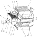
Fig 1 shows a distribution transformer in the first of the embodiment of the invention, having a cover equipped with electronic devices enclosed in the cooling compartment, in an axonometric view with open cross-section over the transformer, -
Fig.2 shows a distribution transformer in the second of the embodiment of the invention, having a cover equipped with electronic devices enclosed in the cooling compartment, in cross-section of the plain view, -
Fig.3 shows a part of the transformer fromfig. 1 , concerning the thermal barrier of a cooling compartment, which is fixed to the transformer cover, in cross-section of the plain view. - An electric power device in the form of a
distribution transformer 1 has acover 2 connected to themain tank 3 filled with theoil 4. Theoil 4 could be a mineral oil, synthetic oil, ester oil and other dielectric liquid. The oil is not indicated on the drawing in a special style. Only the index "4" indicates where the oil is placed. Thecover 2 is equipped with awindow 2a (fig.3 ) in which anexternal cooling compartment 5 is inserted through abottom wall 6 of thecompartment 5. In order to match thebottom wall 6 into thewindow 2a of thecover 2, thebottom wall 6 is equipped with achamfer 6a (fig.3 ) disposed on the entirely circumference of thebottom wall 6. Thecooling compartment 5 is equipped with fourside walls 7 and atop wall 8, forming a rectangular vessel fixed on thecover 2. Inside themain tank 3 anactive part 9 of the transformer is placed having windings electrically connected with MV bushings and with the electric connection of LV terminals. Theactive part 9 is also connected byelastic conductors 10 withelectronic devices 11 placed inside thecooling compartment 5. The electronic devices are presented schematically in the drawing as an oval. In order to connect theconductors 10 with theactive part 9 of the transformer some throughholes 12 are made in thebottom wall 6 of thecompartment 5. Thecooling compartment 5 is filled withoil 4 or other dielectric liquid useful for transformers, the same as filled themain tank 3 so themain transformer tank 3 is hermetically connected with thecooling compartment 5. Thedevice 11 immersed in fluid in cooling compartment can be power electronic tap changer or any other electronic devices connected to active part of the distribution transformer. Thebottom wall 6 of thecooling compartment 5 is fixed to thecover 2 in such a way that theoil 4 can flow throughholes 12 to the cooling compartment from themain tank 3 and vice versa. The through holes 12 are designed in such a way that each of the hole has such a dimension that allows for insertion in it theflexible conductor 10 without using any sealing in each of the through holes 12. Such arrangement leaves the interior of thecooling compartment 5 open to theoil 4 from thetank 3 and there is no need for hermetically insulation. The level of theoil 4 in thecooling compartment 5 is indicated bystandard protection device 13 for measuring a level and the pressure of thedielectric liquid 4 inside thecooling compartment 5, for example Integrated Safety Detector (R.I.S.), connected with theoil 4 located in theoil filing pipe 14 and through aflexible pipe 15, fixed to thetop wall 8 of thecooling compartment 5. When the level of the oil in thecooling compartment 5 is dropped below a threshold level then theprotection device 13 is triggered and theelectric power device 1 is disconnected from the grid to avoid transformer damage. Thebottom wall 6 of thecooling compartment 5 forms a thermal barrier between an interior of themain tank 3 and the interior of thecooling compartment 5, where the powerelectronic devices 11 together with the mechanical systems, not presented in the drawing are placed. In order to form a thermal barrier between themain tank 3 and theexternal cooling compartment 5, thebottom wall 6 is made from a high thermal resistive material having a coefficient of the thermal conductivity not higher than 0,24 W/(m∗K). In the exemplary embodiments of the invention, thebottom wall 6 is made from semicrystalline thermoplastic polyester having the thermal and electrical properties presented in the table 1.Table 1 Parameter Value Unit Density 1,37 g/cm3 Max. service temp. (short term) 170 °C Max. service temp. (long term) 110 °C Coefficient of thermal conductivity 0,24 W/(m*K) Specific heat 1,1 J/(g*K) Surface resistance 1015 Ω Dielectric strength 1 mm60 kV/mm - The
cooling compartment 5 with thebottom wall 6 as the thermal barrier between the interior of themain thank 3 and the interior of thecooling compartment 5 is also equipped withadditional ribs 16 adapted for the oil heat dissipation and presented in the first and second embodiment of the invention. - In the first embodiment of the invention at least one of the
side walls 7 of theenclosure 5 is equipped withexternal ribs 16. The ribs havelongitudinal shape 16A what is presented in the drawing for the twoside walls 7 of thecooling compartment 5. The other shapes of theribs 16 are possible and there many of its are known in the prior art. Theside walls 7 of thecooling compartment 5 are made from material having a high ability to give up the heat, for example from aluminum or the black anodized aluminum. Theribs 16A can be made as integral part of thewalls 7 or can be fixed to the walls as separate parts. The ribs are made from the same material as the walls of the compartment or from other material having the higher ability to give up the heat than the walls. Theside walls 7 can also be carried out as the corrugated walls what is not presented in the drawing. - In the second embodiment of the invention the
top wall 8 of thecooling compartment 5 is also equipped withexternal ribs 16. The ribs on thetop wall 8 havecylindrical shape 16B and they are displaced on the wall in any arbitrary arrangements. The other shapes of the ribs are possible and there many of its are known in the prior art. Thetop wall 8 of thecooling compartment 5 is made from material having a high ability to give up the heat, for example from aluminum or the black anodized aluminum. Theribs 16B can be made as integral part of thewall 8 or can be fixed to the wall as separate parts. Theribs 16B are made from the same material as thetop wall 8 of thecompartment 5 or from other material having the higher ability to give up the heat than the top wall. - In both embodiment of the invention the
cover 2 has others openings for inserting there bushings with conductors, placed outside thebottom wall 6 of thecooling compartment 5, what is not presented in the drawing. In order to avoid a movement of the thermal barrier inside thewindow 2a, additional tie rods and nuts made from fiber glass are fixed to thecover 2, what is not explained in the description. Betweentransformer cover 2 and cooling compartment 5 a rubberflat seal 17 is inserted in order to seal the cooling compartment from the external side of thecover 2. - In the exploitation condition of the invention, the
cover 2 with the thermal barrier in the form of thebottom wall 6 of thecooling compartment 5, works as the following. Inside coolingcompartment 5 theelectronic devises 11 are placed. The electronic devices could be for example the electronic boards containing thyristors, IGBT's or any other power electronic solid state valves. Such electronic devices should have no more than +75°C maximum operation temperature in order to ensure sufficient reliability for 20 years operation. Thehot oil 4 in themain tank 3 can reach temperatures up to 100°C under full load conditions. The ambient air outside the transformer could reach up to +40°C. In the consequence the temperature inside thecooling compartment 5 may be established in a level between those two values. However, the electronic boards generate additional load losses mainly because of the work of thyristors. The heat fluxes strongly depend on the dimensioning of thecooling ribs bottom wall 6 forming the thermal barrier. The barrier allows to isolate oil from hot top oil in themain tank 3 into separate compartment where oil has the lower temperature. A high temperature gradient is provided along the cross-section of the thermal barrier. Generally, the area of the throughholes 12 made in thebottom wall 6 of thecompartment 5 should be as low as possible for limiting the oil mixing of the hot top oil from themain tank 3 with the cool oil from thecooling compartment 5, whereas the area betweencool compartment 5 and ambient air should be vice versa. It is possible to limit the oil temperature inside thecool compartment 5 to around 72°C in such presented conditions. Heat dissipation bywalls cooling compartment 5 withribs 16 is much more significant that heat transfer from the hot top oil via thermal barrier. As a result the temperature of the oil inside thecooling compartment 5 is much lower than the top temperature of the oil in themain tank 3.
Claims (8)
- A cover (2) for covering a distribution transformer (1) with a main tank (3) filled with a dielectric liquid (4) in which an active part (9) of the distribution transformer (1) is placed; the cover (2) has a cooling compartment (5) to be filled with dielectric liquid (4) located at an upper part of the cover (2) and at least one electronic device (11) for electrical connection with the active part (9) of the distribution transformer (1), wherein the cooling compartment (5) has bottom wall (6), side walls (7) and a top wall (8), said electronic device (11) is placed inside the cooling compartment (5), said bottom wall (6) is adapted to form a thermal barrier between the interior of the main tank (3) of the distribution transformer (1) and adapted so that the interior of the cooling compartment (5) and the both interiors of the cooling compartment (5) and of the main tank (3) are hermetically closed together when filled with the dielectric liquid (4), characterized in that the cover (2) is equipped with a window (2a) in which the bottom wall (6) of the cooling compartment (5) is inserted and matched by a chamfer (6a) disposed on the entirely circumference of the bottom wall (6).
- A cover according to claim 1, characterized in that the thermal barrier is made from a high thermal resistive material having a coefficient of the thermal conductivity not higher than 0,24 W/(m∗K).
- A cover according to claims 1 or 2, characterized in that the bottom wall (6) of the cooling device (5) is provided with at least one through hole (12) for insertion of a conductor (10) for electrical connection of the electronic device (11) with the active part (9) of the distribution transformer (1).
- A cover according to claims 1-3, characterized in that said cover (2) comprises an oil filling pipe (14) and a protection device (13) for measuring of a level of the dielectric liquid (4) inside the cooling compartment (5) wherein the protection device (13) is connected with the oil filling pipe and_with the cooling compartment (5) via a flexible pipe (15).
- A cover according to claim 1, characterized in that the at least one side wall (7) of the cooling compartment (5) is equipped with external ribs (16A).
- A cover according to claim 1, characterized in that the top wall (8) of the cooling compartment (5) is equipped with external ribs (16B).
- A cover according to any previous claims, characterized in that the electronic device (11) is a tap-changer device placed in the cooling compartment (5).
- A cover according to claim 7, characterized in that the electronic device (11) is connected with at least one conductor (10) for electrical connection of the electronic device (11) with the active part (9) of the distribution transformer (1), the at least one conductor being inserted in at least one through hole (12) provided in the bottom wall (6) of the cooling compartment (5).
Applications Claiming Priority (2)
| Application Number | Priority Date | Filing Date | Title |
|---|---|---|---|
| EP16460066.0A EP3293743A1 (en) | 2016-09-12 | 2016-09-12 | A cover for electric power devices filled with a dielectric liquid |
| PCT/EP2017/000944 WO2018046113A1 (en) | 2016-09-12 | 2017-08-01 | A cover for a distribution transformer filled with a dielectric liquid |
Publications (2)
| Publication Number | Publication Date |
|---|---|
| EP3510613A1 EP3510613A1 (en) | 2019-07-17 |
| EP3510613B1 true EP3510613B1 (en) | 2020-09-30 |
Family
ID=57083229
Family Applications (2)
| Application Number | Title | Priority Date | Filing Date |
|---|---|---|---|
| EP16460066.0A Withdrawn EP3293743A1 (en) | 2016-09-12 | 2016-09-12 | A cover for electric power devices filled with a dielectric liquid |
| EP17755061.3A Active EP3510613B1 (en) | 2016-09-12 | 2017-08-01 | A cover for a distribution transformer filled with a dielectric liquid |
Family Applications Before (1)
| Application Number | Title | Priority Date | Filing Date |
|---|---|---|---|
| EP16460066.0A Withdrawn EP3293743A1 (en) | 2016-09-12 | 2016-09-12 | A cover for electric power devices filled with a dielectric liquid |
Country Status (4)
| Country | Link |
|---|---|
| US (1) | US11211190B2 (en) |
| EP (2) | EP3293743A1 (en) |
| CN (1) | CN109964289B (en) |
| WO (1) | WO2018046113A1 (en) |
Families Citing this family (4)
| Publication number | Priority date | Publication date | Assignee | Title |
|---|---|---|---|---|
| CN108364754B (en) * | 2018-04-09 | 2019-07-16 | 安徽金环电气设备有限责任公司 | A kind of transformer radiating shell |
| CN108597744B (en) * | 2018-05-29 | 2019-01-25 | 广州市一变电气设备有限公司 | A kind of compact exceeds loading capability low-temperature-rise power transformer |
| EP3761328A1 (en) * | 2019-07-01 | 2021-01-06 | ABB Power Grids Switzerland AG | Electromagnetic induction device with on-load tap changer |
| US20230254996A1 (en) * | 2022-02-07 | 2023-08-10 | Scot Arthur Johnson | Immersion tank assembly |
Family Cites Families (15)
| Publication number | Priority date | Publication date | Assignee | Title |
|---|---|---|---|---|
| US2990528A (en) * | 1960-02-25 | 1961-06-27 | Mc Graw Edison Co | Lightweight distribution transformer |
| US3235823A (en) * | 1961-04-03 | 1966-02-15 | Mc Graw Edison Co | High voltage three phase transformer |
| CN2354276Y (en) * | 1998-10-08 | 1999-12-15 | 上海明昱科技发展有限公司 | Transformer switch integrated desk-kit |
| DE102009035699A1 (en) | 2009-07-30 | 2011-02-10 | Maschinenfabrik Reinhausen Gmbh | Arrangement of a tap changer on a control transformer |
| KR101163422B1 (en) * | 2011-03-07 | 2012-07-13 | 박기주 | Oil immersed transformer |
| US8319590B2 (en) * | 2011-03-21 | 2012-11-27 | Philippe Magnier Llc | Device for explosion prevention of an on load tap changer including a rupture element |
| CN104969409B (en) * | 2013-03-14 | 2018-01-19 | 艾里逊变速箱公司 | The energy storage system of fluid slot refrigeration |
| EP2830072A1 (en) | 2013-07-24 | 2015-01-28 | ABB Technology AG | An electrical lead through connector |
| EP2899728B2 (en) * | 2014-01-22 | 2019-11-13 | ABB Schweiz AG | A device comprising a high voltage apparatus including a fluid and equipment for detecting one or more physical properties of the fluid |
| US20150243428A1 (en) | 2014-02-21 | 2015-08-27 | Varentec, Inc. | Methods and systems of field upgradeable transformers |
| CN204117770U (en) * | 2014-10-31 | 2015-01-21 | 富阳思博工业设计有限公司 | The external oil-filled transformer of a kind of cooling |
| EP3048623B1 (en) * | 2015-01-20 | 2017-11-22 | Balikesir Elektromekanik Sanayi Tesisleri Anonim Sirketi | Transformer with reduced height, volume and weight |
| CN204441030U (en) * | 2015-04-03 | 2015-07-01 | 银河电气科技有限公司 | A kind of low-temperature protection structure of high overload distribution transformer |
| CN204948615U (en) * | 2015-09-29 | 2016-01-06 | 河南新航微波技术有限公司 | A kind of electric elements oil cooling device |
| CN105206381B (en) * | 2015-10-21 | 2017-08-29 | 国家电网公司 | Intelligent power saving increase-volume distribution transformer and monitoring method |
-
2016
- 2016-09-12 EP EP16460066.0A patent/EP3293743A1/en not_active Withdrawn
-
2017
- 2017-08-01 EP EP17755061.3A patent/EP3510613B1/en active Active
- 2017-08-01 WO PCT/EP2017/000944 patent/WO2018046113A1/en not_active Ceased
- 2017-08-01 CN CN201780069769.0A patent/CN109964289B/en active Active
-
2019
- 2019-03-12 US US16/299,777 patent/US11211190B2/en active Active
Non-Patent Citations (1)
| Title |
|---|
| None * |
Also Published As
| Publication number | Publication date |
|---|---|
| EP3510613A1 (en) | 2019-07-17 |
| CN109964289B (en) | 2021-10-15 |
| US11211190B2 (en) | 2021-12-28 |
| EP3293743A1 (en) | 2018-03-14 |
| BR112019004789A2 (en) | 2019-06-04 |
| US20190206605A1 (en) | 2019-07-04 |
| BR112019004789A8 (en) | 2022-12-27 |
| CN109964289A (en) | 2019-07-02 |
| WO2018046113A1 (en) | 2018-03-15 |
Similar Documents
| Publication | Publication Date | Title |
|---|---|---|
| US11211190B2 (en) | Cover for a distribution transformer filled with a dielectric liquid | |
| US5661280A (en) | Combination of a gas-filled interrupter and oil-filled transformer | |
| AU2010214736B2 (en) | High voltage fault current limiter having immersed phase coils | |
| KR20110118682A (en) | Electrical apparatus with electrostatic shield | |
| US12230429B2 (en) | Transportable power transformer unit | |
| US9058926B2 (en) | Fluid insulated high voltage coil | |
| US20140118907A1 (en) | Dielectric Insulated Capacitor Bank | |
| US3369166A (en) | Combination transformer-rectifier apparatus | |
| WO2007078226A1 (en) | Cooling of high voltage devices | |
| EP0208241A1 (en) | A heating unit | |
| US8669469B2 (en) | Cooling of high voltage devices | |
| KR101906134B1 (en) | Power cable termination device for gas-insulated switchgear | |
| BR112019004789B1 (en) | COVERING TO COVER A DISTRIBUTION TRANSFORMER | |
| KR20000016097A (en) | Direct current transformer and reactor | |
| EP4459646A1 (en) | Converter and method of operating a converter | |
| CN116171482B (en) | Tap changer and transformer device | |
| WO2007078238A1 (en) | Cooling of high voltage devices | |
| US516850A (en) | Electrical transformer | |
| NO20201057A1 (en) | Power supply module | |
| CN113016050A (en) | Subsea fuse assembly | |
| Transformers | IEEE PC57. 12.36™/D11 | |
| MXPA98009865A (en) | Transformer / reac |
Legal Events
| Date | Code | Title | Description |
|---|---|---|---|
| STAA | Information on the status of an ep patent application or granted ep patent |
Free format text: STATUS: UNKNOWN |
|
| STAA | Information on the status of an ep patent application or granted ep patent |
Free format text: STATUS: THE INTERNATIONAL PUBLICATION HAS BEEN MADE |
|
| PUAI | Public reference made under article 153(3) epc to a published international application that has entered the european phase |
Free format text: ORIGINAL CODE: 0009012 |
|
| STAA | Information on the status of an ep patent application or granted ep patent |
Free format text: STATUS: REQUEST FOR EXAMINATION WAS MADE |
|
| 17P | Request for examination filed |
Effective date: 20190411 |
|
| AK | Designated contracting states |
Kind code of ref document: A1 Designated state(s): AL AT BE BG CH CY CZ DE DK EE ES FI FR GB GR HR HU IE IS IT LI LT LU LV MC MK MT NL NO PL PT RO RS SE SI SK SM TR |
|
| AX | Request for extension of the european patent |
Extension state: BA ME |
|
| DAV | Request for validation of the european patent (deleted) | ||
| DAX | Request for extension of the european patent (deleted) | ||
| GRAP | Despatch of communication of intention to grant a patent |
Free format text: ORIGINAL CODE: EPIDOSNIGR1 |
|
| STAA | Information on the status of an ep patent application or granted ep patent |
Free format text: STATUS: GRANT OF PATENT IS INTENDED |
|
| INTG | Intention to grant announced |
Effective date: 20200225 |
|
| GRAS | Grant fee paid |
Free format text: ORIGINAL CODE: EPIDOSNIGR3 |
|
| GRAA | (expected) grant |
Free format text: ORIGINAL CODE: 0009210 |
|
| STAA | Information on the status of an ep patent application or granted ep patent |
Free format text: STATUS: THE PATENT HAS BEEN GRANTED |
|
| AK | Designated contracting states |
Kind code of ref document: B1 Designated state(s): AL AT BE BG CH CY CZ DE DK EE ES FI FR GB GR HR HU IE IS IT LI LT LU LV MC MK MT NL NO PL PT RO RS SE SI SK SM TR |
|
| REG | Reference to a national code |
Ref country code: CH Ref legal event code: EP Ref country code: GB Ref legal event code: FG4D |
|
| REG | Reference to a national code |
Ref country code: AT Ref legal event code: REF Ref document number: 1319642 Country of ref document: AT Kind code of ref document: T Effective date: 20201015 |
|
| REG | Reference to a national code |
Ref country code: DE Ref legal event code: R096 Ref document number: 602017024666 Country of ref document: DE |
|
| REG | Reference to a national code |
Ref country code: IE Ref legal event code: FG4D |
|
| PG25 | Lapsed in a contracting state [announced via postgrant information from national office to epo] |
Ref country code: FI Free format text: LAPSE BECAUSE OF FAILURE TO SUBMIT A TRANSLATION OF THE DESCRIPTION OR TO PAY THE FEE WITHIN THE PRESCRIBED TIME-LIMIT Effective date: 20200930 Ref country code: HR Free format text: LAPSE BECAUSE OF FAILURE TO SUBMIT A TRANSLATION OF THE DESCRIPTION OR TO PAY THE FEE WITHIN THE PRESCRIBED TIME-LIMIT Effective date: 20200930 Ref country code: BG Free format text: LAPSE BECAUSE OF FAILURE TO SUBMIT A TRANSLATION OF THE DESCRIPTION OR TO PAY THE FEE WITHIN THE PRESCRIBED TIME-LIMIT Effective date: 20201230 Ref country code: GR Free format text: LAPSE BECAUSE OF FAILURE TO SUBMIT A TRANSLATION OF THE DESCRIPTION OR TO PAY THE FEE WITHIN THE PRESCRIBED TIME-LIMIT Effective date: 20201231 Ref country code: NO Free format text: LAPSE BECAUSE OF FAILURE TO SUBMIT A TRANSLATION OF THE DESCRIPTION OR TO PAY THE FEE WITHIN THE PRESCRIBED TIME-LIMIT Effective date: 20201230 Ref country code: SE Free format text: LAPSE BECAUSE OF FAILURE TO SUBMIT A TRANSLATION OF THE DESCRIPTION OR TO PAY THE FEE WITHIN THE PRESCRIBED TIME-LIMIT Effective date: 20200930 |
|
| REG | Reference to a national code |
Ref country code: AT Ref legal event code: MK05 Ref document number: 1319642 Country of ref document: AT Kind code of ref document: T Effective date: 20200930 |
|
| PG25 | Lapsed in a contracting state [announced via postgrant information from national office to epo] |
Ref country code: LV Free format text: LAPSE BECAUSE OF FAILURE TO SUBMIT A TRANSLATION OF THE DESCRIPTION OR TO PAY THE FEE WITHIN THE PRESCRIBED TIME-LIMIT Effective date: 20200930 Ref country code: RS Free format text: LAPSE BECAUSE OF FAILURE TO SUBMIT A TRANSLATION OF THE DESCRIPTION OR TO PAY THE FEE WITHIN THE PRESCRIBED TIME-LIMIT Effective date: 20200930 |
|
| REG | Reference to a national code |
Ref country code: NL Ref legal event code: MP Effective date: 20200930 |
|
| RAP2 | Party data changed (patent owner data changed or rights of a patent transferred) |
Owner name: ABB POWER GRIDS SWITZERLAND AG |
|
| REG | Reference to a national code |
Ref country code: LT Ref legal event code: MG4D |
|
| PG25 | Lapsed in a contracting state [announced via postgrant information from national office to epo] |
Ref country code: EE Free format text: LAPSE BECAUSE OF FAILURE TO SUBMIT A TRANSLATION OF THE DESCRIPTION OR TO PAY THE FEE WITHIN THE PRESCRIBED TIME-LIMIT Effective date: 20200930 Ref country code: SM Free format text: LAPSE BECAUSE OF FAILURE TO SUBMIT A TRANSLATION OF THE DESCRIPTION OR TO PAY THE FEE WITHIN THE PRESCRIBED TIME-LIMIT Effective date: 20200930 Ref country code: LT Free format text: LAPSE BECAUSE OF FAILURE TO SUBMIT A TRANSLATION OF THE DESCRIPTION OR TO PAY THE FEE WITHIN THE PRESCRIBED TIME-LIMIT Effective date: 20200930 Ref country code: PT Free format text: LAPSE BECAUSE OF FAILURE TO SUBMIT A TRANSLATION OF THE DESCRIPTION OR TO PAY THE FEE WITHIN THE PRESCRIBED TIME-LIMIT Effective date: 20210201 Ref country code: RO Free format text: LAPSE BECAUSE OF FAILURE TO SUBMIT A TRANSLATION OF THE DESCRIPTION OR TO PAY THE FEE WITHIN THE PRESCRIBED TIME-LIMIT Effective date: 20200930 Ref country code: CZ Free format text: LAPSE BECAUSE OF FAILURE TO SUBMIT A TRANSLATION OF THE DESCRIPTION OR TO PAY THE FEE WITHIN THE PRESCRIBED TIME-LIMIT Effective date: 20200930 |
|
| REG | Reference to a national code |
Ref country code: DE Ref legal event code: R081 Ref document number: 602017024666 Country of ref document: DE Owner name: HITACHI ENERGY SWITZERLAND AG, CH Free format text: FORMER OWNER: ABB SCHWEIZ AG, BADEN, CH Ref country code: DE Ref legal event code: R081 Ref document number: 602017024666 Country of ref document: DE Owner name: HITACHI ENERGY LTD, CH Free format text: FORMER OWNER: ABB SCHWEIZ AG, BADEN, CH Ref country code: DE Ref legal event code: R081 Ref document number: 602017024666 Country of ref document: DE Owner name: ABB POWER GRIDS SWITZERLAND AG, CH Free format text: FORMER OWNER: ABB SCHWEIZ AG, BADEN, CH |
|
| PG25 | Lapsed in a contracting state [announced via postgrant information from national office to epo] |
Ref country code: IS Free format text: LAPSE BECAUSE OF FAILURE TO SUBMIT A TRANSLATION OF THE DESCRIPTION OR TO PAY THE FEE WITHIN THE PRESCRIBED TIME-LIMIT Effective date: 20210130 Ref country code: PL Free format text: LAPSE BECAUSE OF FAILURE TO SUBMIT A TRANSLATION OF THE DESCRIPTION OR TO PAY THE FEE WITHIN THE PRESCRIBED TIME-LIMIT Effective date: 20200930 Ref country code: ES Free format text: LAPSE BECAUSE OF FAILURE TO SUBMIT A TRANSLATION OF THE DESCRIPTION OR TO PAY THE FEE WITHIN THE PRESCRIBED TIME-LIMIT Effective date: 20200930 Ref country code: AT Free format text: LAPSE BECAUSE OF FAILURE TO SUBMIT A TRANSLATION OF THE DESCRIPTION OR TO PAY THE FEE WITHIN THE PRESCRIBED TIME-LIMIT Effective date: 20200930 Ref country code: AL Free format text: LAPSE BECAUSE OF FAILURE TO SUBMIT A TRANSLATION OF THE DESCRIPTION OR TO PAY THE FEE WITHIN THE PRESCRIBED TIME-LIMIT Effective date: 20200930 |
|
| PG25 | Lapsed in a contracting state [announced via postgrant information from national office to epo] |
Ref country code: SK Free format text: LAPSE BECAUSE OF FAILURE TO SUBMIT A TRANSLATION OF THE DESCRIPTION OR TO PAY THE FEE WITHIN THE PRESCRIBED TIME-LIMIT Effective date: 20200930 Ref country code: NL Free format text: LAPSE BECAUSE OF FAILURE TO SUBMIT A TRANSLATION OF THE DESCRIPTION OR TO PAY THE FEE WITHIN THE PRESCRIBED TIME-LIMIT Effective date: 20200930 |
|
| REG | Reference to a national code |
Ref country code: DE Ref legal event code: R097 Ref document number: 602017024666 Country of ref document: DE |
|
| PLBE | No opposition filed within time limit |
Free format text: ORIGINAL CODE: 0009261 |
|
| STAA | Information on the status of an ep patent application or granted ep patent |
Free format text: STATUS: NO OPPOSITION FILED WITHIN TIME LIMIT |
|
| PG25 | Lapsed in a contracting state [announced via postgrant information from national office to epo] |
Ref country code: DK Free format text: LAPSE BECAUSE OF FAILURE TO SUBMIT A TRANSLATION OF THE DESCRIPTION OR TO PAY THE FEE WITHIN THE PRESCRIBED TIME-LIMIT Effective date: 20200930 |
|
| 26N | No opposition filed |
Effective date: 20210701 |
|
| PG25 | Lapsed in a contracting state [announced via postgrant information from national office to epo] |
Ref country code: IT Free format text: LAPSE BECAUSE OF FAILURE TO SUBMIT A TRANSLATION OF THE DESCRIPTION OR TO PAY THE FEE WITHIN THE PRESCRIBED TIME-LIMIT Effective date: 20200930 |
|
| PG25 | Lapsed in a contracting state [announced via postgrant information from national office to epo] |
Ref country code: SI Free format text: LAPSE BECAUSE OF FAILURE TO SUBMIT A TRANSLATION OF THE DESCRIPTION OR TO PAY THE FEE WITHIN THE PRESCRIBED TIME-LIMIT Effective date: 20200930 |
|
| REG | Reference to a national code |
Ref country code: GB Ref legal event code: 732E Free format text: REGISTERED BETWEEN 20211104 AND 20211110 |
|
| REG | Reference to a national code |
Ref country code: CH Ref legal event code: PL |
|
| PG25 | Lapsed in a contracting state [announced via postgrant information from national office to epo] |
Ref country code: MC Free format text: LAPSE BECAUSE OF FAILURE TO SUBMIT A TRANSLATION OF THE DESCRIPTION OR TO PAY THE FEE WITHIN THE PRESCRIBED TIME-LIMIT Effective date: 20200930 |
|
| REG | Reference to a national code |
Ref country code: BE Ref legal event code: MM Effective date: 20210831 |
|
| PG25 | Lapsed in a contracting state [announced via postgrant information from national office to epo] |
Ref country code: LI Free format text: LAPSE BECAUSE OF NON-PAYMENT OF DUE FEES Effective date: 20210831 Ref country code: CH Free format text: LAPSE BECAUSE OF NON-PAYMENT OF DUE FEES Effective date: 20210831 |
|
| PG25 | Lapsed in a contracting state [announced via postgrant information from national office to epo] |
Ref country code: IS Free format text: LAPSE BECAUSE OF FAILURE TO SUBMIT A TRANSLATION OF THE DESCRIPTION OR TO PAY THE FEE WITHIN THE PRESCRIBED TIME-LIMIT Effective date: 20210130 Ref country code: LU Free format text: LAPSE BECAUSE OF NON-PAYMENT OF DUE FEES Effective date: 20210801 |
|
| REG | Reference to a national code |
Ref country code: DE Ref legal event code: R081 Ref document number: 602017024666 Country of ref document: DE Owner name: HITACHI ENERGY SWITZERLAND AG, CH Free format text: FORMER OWNER: ABB POWER GRIDS SWITZERLAND AG, BADEN, CH Ref country code: DE Ref legal event code: R081 Ref document number: 602017024666 Country of ref document: DE Owner name: HITACHI ENERGY LTD, CH Free format text: FORMER OWNER: ABB POWER GRIDS SWITZERLAND AG, BADEN, CH |
|
| PG25 | Lapsed in a contracting state [announced via postgrant information from national office to epo] |
Ref country code: IE Free format text: LAPSE BECAUSE OF NON-PAYMENT OF DUE FEES Effective date: 20210801 Ref country code: BE Free format text: LAPSE BECAUSE OF NON-PAYMENT OF DUE FEES Effective date: 20210831 |
|
| PG25 | Lapsed in a contracting state [announced via postgrant information from national office to epo] |
Ref country code: CY Free format text: LAPSE BECAUSE OF FAILURE TO SUBMIT A TRANSLATION OF THE DESCRIPTION OR TO PAY THE FEE WITHIN THE PRESCRIBED TIME-LIMIT Effective date: 20200930 |
|
| P01 | Opt-out of the competence of the unified patent court (upc) registered |
Effective date: 20230527 |
|
| PG25 | Lapsed in a contracting state [announced via postgrant information from national office to epo] |
Ref country code: HU Free format text: LAPSE BECAUSE OF FAILURE TO SUBMIT A TRANSLATION OF THE DESCRIPTION OR TO PAY THE FEE WITHIN THE PRESCRIBED TIME-LIMIT; INVALID AB INITIO Effective date: 20170801 |
|
| REG | Reference to a national code |
Ref country code: DE Ref legal event code: R082 Ref document number: 602017024666 Country of ref document: DE Representative=s name: DENNEMEYER & ASSOCIATES RECHTSANWALTSGESELLSCH, DE Ref country code: DE Ref legal event code: R082 Ref document number: 602017024666 Country of ref document: DE Representative=s name: DENNEMEYER & ASSOCIATES S.A., DE Ref country code: DE Ref legal event code: R081 Ref document number: 602017024666 Country of ref document: DE Owner name: HITACHI ENERGY LTD, CH Free format text: FORMER OWNER: HITACHI ENERGY SWITZERLAND AG, BADEN, CH |
|
| PG25 | Lapsed in a contracting state [announced via postgrant information from national office to epo] |
Ref country code: MK Free format text: LAPSE BECAUSE OF FAILURE TO SUBMIT A TRANSLATION OF THE DESCRIPTION OR TO PAY THE FEE WITHIN THE PRESCRIBED TIME-LIMIT Effective date: 20200930 |
|
| PG25 | Lapsed in a contracting state [announced via postgrant information from national office to epo] |
Ref country code: TR Free format text: LAPSE BECAUSE OF FAILURE TO SUBMIT A TRANSLATION OF THE DESCRIPTION OR TO PAY THE FEE WITHIN THE PRESCRIBED TIME-LIMIT Effective date: 20200930 |
|
| REG | Reference to a national code |
Ref country code: GB Ref legal event code: 732E Free format text: REGISTERED BETWEEN 20240718 AND 20240724 |
|
| PG25 | Lapsed in a contracting state [announced via postgrant information from national office to epo] |
Ref country code: MT Free format text: LAPSE BECAUSE OF FAILURE TO SUBMIT A TRANSLATION OF THE DESCRIPTION OR TO PAY THE FEE WITHIN THE PRESCRIBED TIME-LIMIT Effective date: 20200930 |
|
| REG | Reference to a national code |
Ref country code: DE Ref legal event code: R082 Ref document number: 602017024666 Country of ref document: DE Representative=s name: DENNEMEYER & ASSOCIATES RECHTSANWALTSGESELLSCH, DE |
|
| PGFP | Annual fee paid to national office [announced via postgrant information from national office to epo] |
Ref country code: DE Payment date: 20250820 Year of fee payment: 9 |
|
| PGFP | Annual fee paid to national office [announced via postgrant information from national office to epo] |
Ref country code: GB Payment date: 20250821 Year of fee payment: 9 |
|
| PGFP | Annual fee paid to national office [announced via postgrant information from national office to epo] |
Ref country code: FR Payment date: 20250828 Year of fee payment: 9 |