EP3510284B1 - Micropumps - Google Patents
Micropumps Download PDFInfo
- Publication number
- EP3510284B1 EP3510284B1 EP16763753.7A EP16763753A EP3510284B1 EP 3510284 B1 EP3510284 B1 EP 3510284B1 EP 16763753 A EP16763753 A EP 16763753A EP 3510284 B1 EP3510284 B1 EP 3510284B1
- Authority
- EP
- European Patent Office
- Prior art keywords
- membrane
- micropump
- ipmc
- substrate
- various embodiments
- Prior art date
- Legal status (The legal status is an assumption and is not a legal conclusion. Google has not performed a legal analysis and makes no representation as to the accuracy of the status listed.)
- Active
Links
Images




Classifications
-
- F—MECHANICAL ENGINEERING; LIGHTING; HEATING; WEAPONS; BLASTING
- F04—POSITIVE - DISPLACEMENT MACHINES FOR LIQUIDS; PUMPS FOR LIQUIDS OR ELASTIC FLUIDS
- F04B—POSITIVE-DISPLACEMENT MACHINES FOR LIQUIDS; PUMPS
- F04B19/00—Machines or pumps having pertinent characteristics not provided for in, or of interest apart from, groups F04B1/00 - F04B17/00
- F04B19/006—Micropumps
-
- F—MECHANICAL ENGINEERING; LIGHTING; HEATING; WEAPONS; BLASTING
- F04—POSITIVE - DISPLACEMENT MACHINES FOR LIQUIDS; PUMPS FOR LIQUIDS OR ELASTIC FLUIDS
- F04B—POSITIVE-DISPLACEMENT MACHINES FOR LIQUIDS; PUMPS
- F04B43/00—Machines, pumps, or pumping installations having flexible working members
- F04B43/02—Machines, pumps, or pumping installations having flexible working members having plate-like flexible members, e.g. diaphragms
- F04B43/04—Pumps having electric drive
- F04B43/043—Micropumps
- F04B43/046—Micropumps with piezoelectric drive
-
- F—MECHANICAL ENGINEERING; LIGHTING; HEATING; WEAPONS; BLASTING
- F04—POSITIVE - DISPLACEMENT MACHINES FOR LIQUIDS; PUMPS FOR LIQUIDS OR ELASTIC FLUIDS
- F04B—POSITIVE-DISPLACEMENT MACHINES FOR LIQUIDS; PUMPS
- F04B43/00—Machines, pumps, or pumping installations having flexible working members
- F04B43/12—Machines, pumps, or pumping installations having flexible working members having peristaltic action
- F04B43/14—Machines, pumps, or pumping installations having flexible working members having peristaltic action having plate-like flexible members
Definitions
- Embodiments generally relate to micropumps.
- a micropump is typically the main component of a delivery system that provides the actuation mechanism to deliver specific volumes of target pumping medium (liquids or therapeutic agents/drugs or gases) from a reservoir.
- target pumping medium liquids or therapeutic agents/drugs or gases
- Most mechanical micropumps include a diaphragm membrane, a chamber, an actuator, microchannels, microvalves, an inlet, an outlet, etc..
- non-mechanical micropumps e.g. electrohydrodynamic or electrowetting typically have constraints preventing their utilization in broad use-cases (e.g. restrictions on media conductivity).
- piezoelectrically actuated diaphragms such as piezoelectrically actuated diaphragms, thermopneumatically activated diaphragms, or electrostatically actuated diaphragms.
- Piezoelectrically actuated diaphragms E. Minazara, D. Vasic, F. Costa, G. Poulin, Piezoelectric diaphragm for vibration energy harvesting, Ultrasonics, in: Proceedings of Ultrasonics International (UI'05) and World Congress on Ultrasonics (WCU), vol. 44, Suppl. 1, (2006), pp.699-703 ; J. Kan, K. Tang, G. Liu, G.
- thermopeumatic micropump based on micro-engineering techniques, Sens. Actuators A 21-23, (1990), 198-202 ; D.H. Jun, W.Y. Sim, S.S. Yang, A novel constant delivery thermopneumatic micropump using surface tensions, Sens.
- Actuators A 139 (1-2) (2007) 210-215 ) require low input voltages and may be very compact, but show long thermal time constants. Electrostatically actuated diaphragms ( R. Zengerle, J. Ulrich, S. Kluge, M. Richter, A. Richter, Bidirectional silicon micropump, Sens. Actuators A 50 (1995) 81-86 ; N.-C. Tsai, C.-Y. Sue, Review of MEMS-based drug delivery and dosing systems, Sens. Actuators A: Phys. 134 (2) (2007) 555-564 ) have fast response times and low power consumption, but again require high input voltages. These micropumps are generally for pumping liquid medium. Further, micropumps do not appear to have been investigated for creating forced air flow in consumer electronics such as smart phones or portable particle sensors.
- example embodiments seek to provide a micropump that addresses at least some of the issues identified above.
- US 6390791 B1 discloses a micropump, comprising a substrate and a membrane attached to the substrate, wherein the membrane is deformable away from the substrate to increase a volume enclosed by the substrate and the membrane, and wherein a portion of the membrane is configured to be an inlet for entry into the volume.
- US 5 759 014 also covers a micropump, comprising a substrate and a membrane attached to the substrate, wherein the membrane is deformable away from the substrate to increase a volume enclosed by the substrate and the membrane, and wherein a portion of the membrane is configured to be an inlet for entry into the volume.
- WO 2006 036888 A2 refers to solid polymer electrolyte composite membranes and shows a membrane comprising an ionic polymer-metal composite.
- CN 204951206 U and CN 103424283 discloses the combination of a portable electronic device comprising a micropump.
- micropump as claimed in claim 1 is provided.
- IPMC Ionic polymer-metal composites
- Ionic polymer-metal composites may require very low currents and voltages. Further, IPMC materials may operate in both air and liquid media ( J.W.L. Zhou, H.-Y. Chan, T.K.H. To, K.W.C. Lai, W.J. Li, Polymer MEMS actuators for underwater micromanipulation, IEEE/ASME Trans. Mechatron 9 (2004) 334-340 ) and may be very flexible. According to various embodiments, IPMC which generates high bending displacement at low applied current and voltage may be a promising actuator technology and may be used to create diaphragm based micropump for creating forced air flow (pumping medium is gas/air) in consumer electronics.
- IPMC based micropump for consumer electronics application (especially creating forced air flow for particle sensing).
- sensors e.g. particle counter sensors, Gas sensors
- low voltage operated micropump technologies may be highly appreciated.
- various embodiments seek to provide an IPMC based micropump for use in consumer electronics application (e.g. smart phones).
- IPMC IPMC technology
- Various embodiments seek to use IPMC technology to provide micropump which operates at low voltages ( ⁇ 3V) to create forced air flow for particle sensing or gas sensing around the sensors, such as particle sensors or gas sensors, which may be built in smart phones or portable sensors.
- Ionic polymers ionic polymer-metal composites or IPMC
- EAP electro active polymers
- the IPMC may be composed of an ionic polymer electrolyte whose both surfaces are plated with electrodes. Under an applied voltage (range of 1-5V), ion migration and redistribution due to the imposed voltage across an IPMC may result in a bending deformation which may allow the IPMC to perform as actuator. Alternatively, if such deformations are physically applied to an IPMC, an output voltage signal (of millivolts range) may be generated similar to a sensor.
- ionic polymer actuator may exhibit a large bending displacement under very low applied voltage and such mechanical deformation may be applied in micropump application ( Fang, T., Tan, X., A novel diaphragm micropump actuated by conjugated polymer petals: Fabrication, modeling, and experimental results, Sens. Actuators A (2010), 158, 121-131 ; Jeon, JH, Oh, IK, Snap-through Dynamics of Curved IPMC Diaphragm for Bio-medical Micro-Pump, Jeonbuk National University, MFMS 2010 The 3rd International Conference on MultiFunctional Materials and Structures, v., no., pp.-, Sep-2010 ).
- IPMC which requires very low currents and voltages makes it a promising candidate for actuating diaphragms in micropump devices for consumer electronics.
- the key elements in the development of ionic polymers based micropump for consumer electronics are miniaturization, simple and flexible configuration based on active thin films, low voltage driving mechanisms and large discharge volumes with high back pressures.
- Various embodiments may provide a micropump which may provide great pumping force, large volume and a large displacement, to obtain a greater pumping power.
- Various embodiments may include a stacked actuator approach (stacking the individual IPMC actuator while maintaining electrical connection in the stack), flexible boundary conditions (such as using less stiff materials compared to IPMC), petal shaped diaphragms for larger out-of-plane deformation, active layers/boundary regions at center via adopting the in-plane deformation using conducting polymer and DEAP actuators, novel diaphragm with buckled IPMC strips, and/or with micro/macro holes used to improve the pumping force, displacement and volume.
- the micropump may be a simple device that is easy to manufacture and/or operate because the membrane itself is also the actuator, thus the setup of the micropump includes only very few layers (e.g. IPMC layer & metallization layer).
- the micropump may be lightweight as only a single membrane is used for both pumping and actuation. Further, the material may be lightweight and metallization may be thin.
- the micropump may be flexible as the membrane may be easily formed (for example cut or stencilled) to adapt the use-case requirements.
- the micropump may be strong as the ionic diffusion may lead to a high force of the actuator compared to other actuation mechanisms. The strength may be adapted by stacking the actuator / membrane layers. Pre-stacked membranes barely impede the aforementioned advantages although there is slight increase in weight.
- the micropump may have enhanced performance as special shapes and arrangements may further improve the already large inherent deformation / displacement of the IPMC material for higher pump volumes.
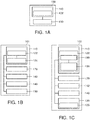
- FIG. 1A shows a schematic diagram of a micropump 100 according to various embodiments.
- the micropump 100 may include a substrate 130.
- the micropump 100 may further include a membrane 110 attached to the substrate 130.
- the membrane 110 may be deformable away from the substrate 130 to increase a volume enclosed by the substrate 130 and the membrane 110. Further, a portion of the membrane 110 may be configured to be an inlet 122 for entry into the volume.
- a micropump may include a layer of flexible material forming a diaphragm joined to a support structure.
- the diaphragm may be bendable such that the diaphragm may bend away from the support structure so as to increase a volume of a space enveloped by the diaphragm and the support structure.
- a part or a section of the diaphragm may be adapted to be an entry point for access into the space between the diaphragm and the support structure.
- FIG. 1B shows a schematic diagram of a micropump 101 according to various embodiments.
- the micropump 101 may, similar to the micropump 100 in FIG. 1A , include a substrate 130.
- the micropump 101 may, similar to the micropump 100 in FIG. 1A , further include a membrane 110 attached to the substrate 130.
- the membrane 110 is deformable away from the substrate 130 to increase a volume enclosed by the substrate 130 and the membrane 110 and a portion of the membrane 110 is configured to be an inlet 122 for entry into the volume.
- the inlet 122 includes a folded-in portion of a suitably shaped section of a perimeter of the membrane 110.
- the perimeter of the membrane 110 may be a boundary, an edge, a periphery, a circumferential edge, a fringe of the membrane 110.
- the suitably shaped section of the perimeter of the membrane 110 forming the inlet 122 may not be attached or secured to the substrate 130.
- the membrane 110 may also include another suitably shaped section of the perimeter of the membrane 110 forming an outlet 124, which may also not be attached or secured to the substrate 130. Accordingly, the membrane 110 may only be attached to the substrate 130 along sections of the perimeter of the membrane 110 which do not form the inlet 122 or the outlet 124.
- FIG. 1C shows a schematic diagram of a micropump 102 according to various embodiments.
- the micropump 101 may, similar to the micropumps 100, 101 in FIGs. 1A and 1B , include a substrate 130.
- the micropump 101 may, similar to the micropumps 100, 101 in FIGs. 1A and 1B , further include a membrane 110 attached to the substrate 130.
- the membrane 110 may be deformable away from the substrate 130 to increase a volume enclosed by the substrate 130 and the membrane 110 and a portion of the membrane 110 may be configured to be an inlet 122 for entry into the volume.
- the inlet 122 may include a hole in the membrane 110.
- the hole 180 may be located on a surface of the membrane 110 and may form an opening through the membrane 110.
- the inlet 122 may include a check valve 190 at the hole 180.
- the check valve 190 may be a passive check valve in the form of a flap valve.
- the check valve 190 may also be an active check valve in the form of a conducting polymer actuator controllable to expand in order to close the valve and controllable to contract in order to open the valve.
- the membrane 110 may include a plurality of holes 180. The plurality of holes 180 may be scattered across the surface of the membrane 110.
- an outlet 125 may be formed in the substrate 130.
- the membrane 110 may include an ionic polymer-metal composite membrane.
- the membrane 110 may include any one of a circular shape, an eccentric shape, an ellipse shape, a petals shape, or a donut shape with an opened sector.
- the membrane 110 may be attached to the substrate 130 along, at least, a section of a perimeter of the membrane 110.
- the micropump 100, 101, 102 may include a boundary suspension component 140 along a perimeter of the membrane 110.
- the boundary suspension component 140 may be a passive component in the form of a flexible, elastic, stretchable material connecting the membrane 110 to the substrate 130.
- the boundary suspension component 140 may also be an active component in the form of conducting polymer or dielectric electro active polymer.
- the boundary suspension component 140 may allow larger in-plane deformation of the membrane 110.
- the membrane 110 may include a thickness profile with a thickness of a centre of the membrane 110 thinner than a thickness of the membrane 110 at an edge along a perimeter of the membrane 110.
- the micropump 100, 101, 102 may further include an active layer 170 deposited on the membrane 110.
- the active layer 170 may include conducting polymer or dielectric electroactive polymer.
- the micropump 100, 101, 102 may further include an elastic layer 142 laid over the membrane 110.
- the elastic layer 142 may be a very thin elastic membrane.
- the membrane 110 may include a buckled strip with curved cross-section.
- the membrane 110 may include multiple buckled strips with curved cross-section joined together to form a petals shape membrane.
- Various embodiments may also provide a micropump including an enclosed chamber.
- the micropump may include a membrane partitioning the enclosed chamber into a first chamber and a second chamber.
- the micropump may further include a first inlet and a first outlet connected to the first chamber, and a second inlet and a second outlet connected to the second chamber.
- Various embodiments may also provide a portable electronic device including a micropump as described above.
- the portable electronic device may include mobile phones, smart phones, personal digital assistant (PDA), tablets, mobile computers, notebook, laptop, or other suitable devices.
- PDA personal digital assistant
- Various embodiments may also provide a portable electronic device including a micropump having an ionic polymer-metal composite membrane.
- Various embodiments may also provide a portable electronic device including a micropump configured to create forced air flow for particle sensing or gas sensing around sensors, such as particle sensors or gas sensors, which may be built inside the portable electronic device.
- FIGs. 2A to 2C illustrate various embodiments of an IPMC membrane/diaphragm with conducting metal electrodes.
- FIG. 2A illustrates an IPMC membrane 210 in the form of a cantilever structure and the layer setup of the IPMC membrane.
- the IPMC membrane 210 may include an ionic polymer electrolyte layer 211 sandwiched between two metal electrodes 213.
- FIG. 2B shows a circular IPMC membrane 212.
- FIG. 2C shows a rectangular IPMC membrane 214.
- the IPMC membrane may allow different mechanical deformation and may determine the total chamber volume which may in turn be related to the flow rate.
- the metal electrodes may include platinum (Pt), silver (Ag), gold (Au) etc.
- FIG. 3 shows a bending deformation of an IPMC membrane 310 under applied voltage.
- a voltage applied across the IPMC membrane 310 which include an ionic polymer electrolyte layer 311 sandwiched between two electrodes 313, may result in a bending deformation of the IPMC membrane 310.
- FIGs. 4A to 4C show a micropump 400 using an IPMC membrane 410 in pulse pumping mode according to various embodiments.
- the micropump 400 may include a pumping chamber or chamber 420 constructed using e.g. an acrylic casing with inlet 422 and outlets 424 on the sides or through a base plate.
- Arrow 421 in FIG. 4A shows air in-flow and arrow 423 in FIG. 4C shows air out-flow.
- the microvalve 426 may be a passive microvalve made from suitable, flexible material (polymer).
- the microvalve 426 may be an active microvalve made of the same IPMC material to control the pumping sequence and to prevent back flowing of the target medium.
- the microvalve 426 may be check valves having the same ionic electroactive polymer (iEAP) material as the membrane 410.
- Pumping volume may be defined by the IPMC membrane 410 displacement and area covered in the actuation mode as well as by the shape of the rest of the housing.
- IPMC membrane 410 may be attached to the acrylic chamber walls which may define the boundary condition of the membrane suspension. Flexible boundary condition may be achieved by attaching less stiff materials (e.g. a flexible membrane such as PDMS, elastic elastomer, etc..) first to the chamber walls and then to the IPMC membrane 410.
- a voltage across the inlet check valve may also be on to open up the inlet check valve.
- FIG. 4C illustrates how the pumping medium may be pushed out of the chamber 420 of the micropump 400.
- IPMC membrane 410 may move upwards displacing the volume to outlet 424 for flowing to the measurement chamber (not shown).
- FIGs. 5A to 5C show a micropump 500 using an IPMC membrane 510 in continuous pumping mode according to various embodiments.
- the micropump 500 may include the IPMC membrane 510 and a dual port configuration to achieve continuous pumping.
- Arrow 525 in FIG. 5A shows air in-flow and arrows 527 in FIG. 5B and 5C show air out-flow for flowing to a measurement chamber.
- the microvalves 526 may be check valves having the same iEAP material as the membrane 510, at inlets 522 and outlets 524 to control the pumping sequence and to prevent back flowing of the target medium at every half cycle (suction / ejection) for the respective cavity above or below the membrane 510.
- the micropump 500 may include a pumping chamber or chamber 520 constructed using e.g. an acrylic casing. As shown in FIG. 5A , the IPMC membrane 510 may divide the chamber 520 into a top chamber 521 and a bottom chamber 523. Each of the top chamber 521 and the bottom chamber 523 may include an inlet 522 and an outlet 524. Accordingly, the micropump 500 may include two inlets 522 and two outlets 524.
- a voltage across the inlet valve in the top half 521 of the chamber 520 and the outlet valve in the bottom half 523 of the chamber 520 may be on.
- FIG. 5C illustrates the opposite of FIG. 5B.
- FIG. 5C shows the micropump 500 with the IPMC membrane 510 actuated under positive bias, for example a positive voltage is provided (e.g.
- V +2V
- FIG. 6A shows a top view and a cross-sectional view of a minimalistic micropump 600 in an open setup according to various embodiments.
- "open" means no tubing connection to the micropump 600 and pumping is from one side of a membrane 610, e.g. an IPMC membrane, to another side of the membrane 610.
- a membrane 610 e.g. an IPMC membrane
- ambient air may be suck into the micropump 600 at a section of a perimeter of the membrane 610 and may be expel from the micropump 600 at another section of the perimeter of the membrane 610.
- the minimalistic approach may include attaching the actuator membrane 610 on a suitable base plate 630, e.g. a glass or polymer substrate, to form a pump chamber 618.
- the sides 616 of the membrane 610, or sections of the perimeter of the membrane 610 may be fixed (e.g. welded or glued) either directly to the base plate 630 or via an elastic suspension to reduce stress on the membrane 610 upon actuation.
- the outlet valve 624 may include a non-fixed section on the membrane side, or a unfasten section of the perimeter of the membrane 610, suitably shaped to allow for passive actuation (as will be described below with reference to FIGs. 6B and 6C ) and optionally disconnected from the electrical actuation mechanism.
- the inlet valve 622 may be either a suitably shaped section from the membrane 610 folded in and favourably likewise disconnected from the electrical connections, or according to an arrangement not under the scope of the invention a separate membrane with optimized shape and properties, sealed to the actuator membrane 610. Similarly, the inlet valve 622 may be a non-fixed section of the membrane side or a unfasten section of the perimeter of the membrane 610. The inlet valve 622 may include a passive polymer glued or welded to an edge of the membrane 610.
- FIGs. 6B and 6C show the operation of the micropump 600 of FIG. 6A according to various embodiments.
- the membrane 610 Upon actuation, the membrane 610 lifts, thereby increasing the volume between the membrane 610 and the base plate 620, and decreasing the pressure in the pump cavity 618.
- the outlet section 624 of the actuation membrane 610 may be sucked in, increasing the tightness, while the inlet section 622 of the actuation membrane may be pulled open, allowing fluid to flow into the pump cavity 618.
- the membrane 610 may be pushed down, closing the inlet valve section 622 and increasing the pressure in the pump cavity 618.
- the non-fixed outlet section 624 may be pushed open and the fluid may be ejected.
- the open character of the embodiment may be modified and may be connected to flexible or solid tubings.
- various embodiments may allow very flat micropumps 600 with very low dead volume of the pump, high compression ratios (pump volume/dead volume) and thus excellent back or front pressure performance of the pump may be expected.
- Adequate tubing and setup of the pump and pump membrane/actuator 610 may help leverage this advantage.
- Further embodiments may have passive valve placements not only at the border and at opposite sides, but at different angles and/or in the membrane 610 and/or the base plate 630.
- Other embodiments may use several membranes 610 in serial connection or an elongated membrane with suitable electrodes for an undular, peristaltic movement to realize a peristaltic pump.
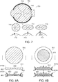
- FIG. 7 shows a top view 701 of a micropump 700 according to various embodiments along with various configurations of the membrane for the micropump 700.
- the micropump 700 may be based on the minimalistic and open setup concept for realizing ionic electroactive polymer (iEAP) or IPMC based micropump with glue/welded edges.
- iEAP ionic electroactive polymer
- IPMC IPMC based micropump with glue/welded edges.
- flexible, elastic and stretchable boundary suspension components 740 may be provided as supporting walls and spacers.
- the boundary suspension components 740 may be glued/welded with a glass or polymer substrate to make sufficient room for air-forced micropump 700.
- very low elastic protective layer e.g. ultra-thin elastomer, (not shown) may be applied to petals shape circular membrane/diaphragm 710.
- FIGs. 6B and 6C other configurations of the membrane 710 such as ellipse shape membrane 714 or eccentric shape membrane 712 or eccentric and ellipse shape membrane 716 along with consideration of their respective centroid may be considered for realization of larger undular and peristaltic movement for natural pumping sequence as presented in FIGs. 6B and 6C .
- Cross-sectional views 713, 715, 717 of the eccentric shape membrane 712 or ellipse shape membrane 714 or eccentric and ellipse shape membrane 716 respectively shows larger stroke volume, ⁇ V, with undular and peristaltic motion.
- reverse connection to two-segment actuator strip with two through-holes may be adopted for natural pumping sequence including undular and peristaltic movements in its tail part.
- FIGs. 8A to 8D show various embodiments of an IPMC membrane/diaphragm 810, 811, 812, 813.
- the IPMC membranes 810, 811, 812, 813 may generate larger out-of-plane deformation such that a larger pumping volume and a greater pumping power may be achieved.
- FIG. 8A shows an IPMC membrane 810 with a gradient thickness 860 in centripetal direction, i.e. the thinner thickness at the center point, according to various embodiments.
- Cross-sectional views 801a, 801b of IPMC membrane 810 show that the gradient thickness 860 along the centripetal direction may include thicker roots 862 and gradually thinner toward a center part 866 for higher stiffness and larger generating force at root, and lower bending stiffness and higher out-of-plane deformation at center, respectively. Accordingly, the gradient thickness 860 may have a thickness profile with a thickness at the centre 866 of the membrane 810 thinner than a thickness of the membrane 810 at the edge 862 along the perimeter of the membrane 810.
- FIG. 8B shows an IPMC membrane 811 with active layers 870 deposited on its surfaces according to various embodiments.
- Cross-sectional side views 803a, 803b show that the active layers 870 may include conducting polymer (CP) actuators, which may be capable of generating in-plane deformation, resulting in triggering of the buckling mode and snap-through behaviour for a larger out-of-plane deformation of the IPMC membrane 811.
- the membrane 811 may include the gradient thickness 860 similar to that of the membrane 810.
- FIG. 8C shows an IPMC membrane 812 with passive/active boundary region/configurations 840 or boundary suspension component according to various embodiments.
- Cross-sectional side view 805a, 805b shows that the passive/active boundary region may be at the edge of the perimeter of the IPMC membrane 812.
- the passive boundary configuration 840 may include elastomers to form a stretchable boundary region.
- the active boundary configurations 840 may include conducting polymer/dielectric electroactive polymer (CP/DEAP) actuators to allow larger in-plane deformation resulting from the expansion and contraction under electrical excitation.
- the boundary configuration may allow membrane 812 to have larger bending locomotion due to the triggering effect via CP/DEAP actuators, i.e.
- FIG. 8D shows a donut shaped iEAP/IPMC membrane/diaphragm 813 with open ends.
- Cross-sectional side views 807a, 807b shows that the donut shaped with open ends may make it possible for a larger out-of-plane deformation.
- the passive boundary region 840 e.g. elastomers with very low elastic modulus
- active boundary region 840 e.g. conducting polymer, DEAP
- packaging and encapsulation as well as in-plane deformation may be possible.
- a thin elastic layer or very thin elastic membrane 842 may be applied to the membrane 813.
- FIGs. 9A and 9B show various embodiments of petals shape membrane/diaphragm 910, 911 with buckled and initially curved IPMC strips/actuators forming the membrane/diaphragm.
- a thin elastic layer 942 may be a passive boundary and may be in the form of elastomer with low elastic modulus applied to the membranes 910, 911.
- the iEAP/IPMC membranes 910, 911 may be in a petals shape.
- FIG. 9A shows a membrane 910 formed by double clamp-type buckled IPMC strips 914 with concave shape with a narrow width at the center point, and a concave longitudinal profile 916, which may generate much larger, stable and repeatable movement.
- the IPMC strips 914 may include curved cross section 917 which may trigger their elastic instabilities for generating larger deformation and pumping performance due to providing variable stiffness based on structural changes related to polymer deflection.
- FIG. 9B shows a membrane 911 formed by cantilever-type buckled IPMC strips 915.
- the IPMC strips 915 may have a concave shape with a narrow width at a tip point, a curved longitudinal profile 916 and a curved cross section 917. The effect of initial curvature and total shape of donut-shaped membrane encapsulated with very thin elastic film 942 may generate efficient snap-through motion for large stroke and efficient pumping power.
- FIG. 10A shows a simple membrane/diaphragm 1010 configuration with small/macro-size/micro-size holes 1080 including passive/active check valves 1092, 1094 according to various embodiments.
- a thin elastic layer or very thin elastic membrane 1042 may be applied to the membrane 1010.
- the membrane 1010 may be formed by IPMC strips 1015 and arranged in a petals shape. This configuration may have the following advantages. Larger out-of-plane deformation of petals shape IPMC membrane 1010 may be achieved due to lower aerodynamic resistance and mechanical bending stiffness during up-stroke, resulting from micro/macro-size holes 1080 on membrane 1010. Enhancement of pumping performance and its efficiency may be achieved. Adoption of efficient passive valve 1092 (eg.
- a micropump 1000 ( FIG. 10B ) having the membrane 1010 may be of a simple configuration without inlets built into the substrate of the micropump 1000. Rather, the membrane 1010 of the micropump 1000 itself may provide the inlet.
- FIG. 10B shows a working mechanism of the micropump 1000 having the membrane 1010 configuration with small holes 1080 including passive check valves 1092, which may function as inlet for the micropump 1000.
- the membrane 1010 may be attached to a substrate 1030 having an inner cavity 1031. Accordingly, a stroke volume, ⁇ V, 1099 of the membrane 1010 may be as shown in FIG. 10B .
- the outlet 1025 may be in the substrate 1030.
- Methods according to various embodiments may be applied in the fabrication of embedded high aspect ratio channels and cavities for downhole tools in the oil and gas industry.
- the methods may also be extended for applications in marine, automotive and aerospace industries where similar requirements arise.
Landscapes
- Engineering & Computer Science (AREA)
- Mechanical Engineering (AREA)
- General Engineering & Computer Science (AREA)
- Reciprocating Pumps (AREA)
Description
- Embodiments generally relate to micropumps.
- A micropump is typically the main component of a delivery system that provides the actuation mechanism to deliver specific volumes of target pumping medium (liquids or therapeutic agents/drugs or gases) from a reservoir. Most mechanical micropumps include a diaphragm membrane, a chamber, an actuator, microchannels, microvalves, an inlet, an outlet, etc.. On the other hand, non-mechanical micropumps (e.g. electrohydrodynamic or electrowetting) typically have constraints preventing their utilization in broad use-cases (e.g. restrictions on media conductivity).
- Conventionally, for the operation of the compact mechanical micropump, there is a number of different actuation mechanisms, such as piezoelectrically actuated diaphragms, thermopneumatically activated diaphragms, or electrostatically actuated diaphragms. Piezoelectrically actuated diaphragms (E. Minazara, D. Vasic, F. Costa, G. Poulin, Piezoelectric diaphragm for vibration energy harvesting, Ultrasonics, in: Proceedings of Ultrasonics International (UI'05) and World Congress on Ultrasonics (WCU), vol. 44, Suppl. 1, (2006), pp.699-703; J. Kan, K. Tang, G. Liu, G. Zhu, C. Shao, Development of serial-connection piezoelectric pumps, Sens. Actuators A 144 (2) (2008), 321-327) produce high actuation forces and fast mechanical responses, but also require high input voltages. Thermopneumatically activated diaphragms (F.C.M. van de Pol, H.T.G. van Lintel, M. Elwenspoek, J.H.J. Fluitam, A thermopeumatic micropump based on micro-engineering techniques, Sens. Actuators A 21-23, (1990), 198-202; D.H. Jun, W.Y. Sim, S.S. Yang, A novel constant delivery thermopneumatic micropump using surface tensions, Sens. Actuators A 139 (1-2) (2007) 210-215) require low input voltages and may be very compact, but show long thermal time constants. Electrostatically actuated diaphragms (R. Zengerle, J. Ulrich, S. Kluge, M. Richter, A. Richter, Bidirectional silicon micropump, Sens. Actuators A 50 (1995) 81-86; N.-C. Tsai, C.-Y. Sue, Review of MEMS-based drug delivery and dosing systems, Sens. Actuators A: Phys. 134 (2) (2007) 555-564) have fast response times and low power consumption, but again require high input voltages. These micropumps are generally for pumping liquid medium. Further, micropumps do not appear to have been investigated for creating forced air flow in consumer electronics such as smart phones or portable particle sensors.
- Accordingly, example embodiments seek to provide a micropump that addresses at least some of the issues identified above.
In this regard,US 6390791 B1 discloses a micropump, comprising a substrate and a membrane attached to the substrate, wherein the membrane is deformable away from the substrate to increase a volume enclosed by the substrate and the membrane, and wherein a portion of the membrane is configured to be an inlet for entry into the volume. Further,US 5 759 014 also covers a micropump, comprising a substrate and a membrane attached to the substrate, wherein the membrane is deformable away from the substrate to increase a volume enclosed by the substrate and the membrane, and wherein a portion of the membrane is configured to be an inlet for entry into the volume. Further,WO 2006 036888 A2 refers to solid polymer electrolyte composite membranes and shows a membrane comprising an ionic polymer-metal composite.CN 204951206 U andCN 103424283 discloses the combination of a portable electronic device comprising a micropump. - According to the present invention, a micropump as claimed in claim 1 is provided.
- In the drawings, like reference characters generally refer to the same parts throughout the different views. The drawings are not necessarily to scale, emphasis instead generally being placed upon illustrating the principles of the invention. In the following description, various embodiments are described with reference to the following drawings, in which:
-
FIGs. 1A to 1C show schematic diagrams of various embodiments of a micropump; -
FIGs. 2A to 2C show various embodiments of a membrane with conducting metal electrodes; -
FIG. 3 shows a bending deformation of an IPMC membrane under applied voltage; -
FIGs. 4A to 4C show a micropump using an IPMC membrane in pulse pumping mode according to various embodiments; -
FIGs. 5A to 5C show a micropump using an IPMC membrane in continuous pumping mode according to various embodiments; -
FIG. 6A shows a top view and a cross-sectional view of a micropump in an open setup according to various embodiments; -
FIGs. 6B and 6C show the operation of the micropump ofFIG. 6A according to various embodiments; -
FIG. 7 shows a top view of a micropump according to various embodiments along with various configurations of the membrane for the micropump; -
FIGs. 8A to 8D show various embodiments of an IPMC membrane; -
FIGs. 9A and 9B shows various embodiments of petals shape membrane with buckled and initially curved IPMC strips forming the membrane; -
FIG. 10A shows a membrane with small holes and check valves according to various embodiments; and -
FIG. 10B shows a working mechanism of the membrane with small holes including passive check valves. - Ionic polymer-metal composites (IPMC) materials may require very low currents and voltages. Further, IPMC materials may operate in both air and liquid media (J.W.L. Zhou, H.-Y. Chan, T.K.H. To, K.W.C. Lai, W.J. Li, Polymer MEMS actuators for underwater micromanipulation, IEEE/ASME Trans. Mechatron 9 (2004) 334-340) and may be very flexible. According to various embodiments, IPMC which generates high bending displacement at low applied current and voltage may be a promising actuator technology and may be used to create diaphragm based micropump for creating forced air flow (pumping medium is gas/air) in consumer electronics. To date, there is no reported work on IPMC based micropump for consumer electronics application (especially creating forced air flow for particle sensing). With the inclusion of variety of sensors to new smart phones (e.g. particle counter sensors, Gas sensors) low voltage operated micropump technologies may be highly appreciated.
- Accordingly, various embodiments seek to provide an IPMC based micropump for use in consumer electronics application (e.g. smart phones). Various embodiments seek to use IPMC technology to provide micropump which operates at low voltages (<3V) to create forced air flow for particle sensing or gas sensing around the sensors, such as particle sensors or gas sensors, which may be built in smart phones or portable sensors.
- Ionic polymers (ionic polymer-metal composites or IPMC), another sub-group of electro active polymers (EAP), may be a promising candidate for a micropump (Nguyen, T.T.; Goo, N.S.; Nguyen, V.K.; Yoo, Y.; Park, S. Design, fabrication, and experimental characterization of a flap valve IPMC micropump with a flexibly supported diaphragm, Sens. Actuators A 2008, 141, 640-648; Il-Kwon Oh et al, Snap-through Phenomena on Nonlinear Thermopiezoelastic Behavior of piezolaminated Plates, Journal of Astronomy and Space Sciences vol. 30, no. 1, 01 February 2002). The IPMC may be composed of an ionic polymer electrolyte whose both surfaces are plated with electrodes. Under an applied voltage (range of 1-5V), ion migration and redistribution due to the imposed voltage across an IPMC may result in a bending deformation which may allow the IPMC to perform as actuator. Alternatively, if such deformations are physically applied to an IPMC, an output voltage signal (of millivolts range) may be generated similar to a sensor. Compared to other EAP actuator materials, ionic polymer actuator may exhibit a large bending displacement under very low applied voltage and such mechanical deformation may be applied in micropump application (Fang, T., Tan, X., A novel diaphragm micropump actuated by conjugated polymer petals: Fabrication, modeling, and experimental results, Sens. Actuators A (2010), 158, 121-131; Jeon, JH, Oh, IK, Snap-through Dynamics of Curved IPMC Diaphragm for Bio-medical Micro-Pump, Jeonbuk National University, MFMS 2010 The 3rd International Conference on MultiFunctional Materials and Structures, v., no., pp.-, Sep-2010). Typically, high operating voltages are difficult to manage in consumer electronics with common battery packs such as smart phones. Thus, IPMC which requires very low currents and voltages makes it a promising candidate for actuating diaphragms in micropump devices for consumer electronics.
- In various embodiments, the key elements in the development of ionic polymers based micropump for consumer electronics are miniaturization, simple and flexible configuration based on active thin films, low voltage driving mechanisms and large discharge volumes with high back pressures.
- Various embodiments may provide a micropump which may provide great pumping force, large volume and a large displacement, to obtain a greater pumping power. Various embodiments may include a stacked actuator approach (stacking the individual IPMC actuator while maintaining electrical connection in the stack), flexible boundary conditions (such as using less stiff materials compared to IPMC), petal shaped diaphragms for larger out-of-plane deformation, active layers/boundary regions at center via adopting the in-plane deformation using conducting polymer and DEAP actuators, novel diaphragm with buckled IPMC strips, and/or with micro/macro holes used to improve the pumping force, displacement and volume.
- According to various embodiments, the micropump may be a simple device that is easy to manufacture and/or operate because the membrane itself is also the actuator, thus the setup of the micropump includes only very few layers (e.g. IPMC layer & metallization layer). The micropump may be lightweight as only a single membrane is used for both pumping and actuation. Further, the material may be lightweight and metallization may be thin. The micropump may be flexible as the membrane may be easily formed (for example cut or stencilled) to adapt the use-case requirements. The micropump may be strong as the ionic diffusion may lead to a high force of the actuator compared to other actuation mechanisms. The strength may be adapted by stacking the actuator / membrane layers. Pre-stacked membranes barely impede the aforementioned advantages although there is slight increase in weight. The micropump may have enhanced performance as special shapes and arrangements may further improve the already large inherent deformation / displacement of the IPMC material for higher pump volumes.
-
FIG. 1A shows a schematic diagram of amicropump 100 according to various embodiments. Themicropump 100 may include asubstrate 130. Themicropump 100 may further include amembrane 110 attached to thesubstrate 130. Themembrane 110 may be deformable away from thesubstrate 130 to increase a volume enclosed by thesubstrate 130 and themembrane 110. Further, a portion of themembrane 110 may be configured to be aninlet 122 for entry into the volume. - In other words, a micropump may include a layer of flexible material forming a diaphragm joined to a support structure. The diaphragm may be bendable such that the diaphragm may bend away from the support structure so as to increase a volume of a space enveloped by the diaphragm and the support structure. A part or a section of the diaphragm may be adapted to be an entry point for access into the space between the diaphragm and the support structure.
-
FIG. 1B shows a schematic diagram of amicropump 101 according to various embodiments. Themicropump 101 may, similar to themicropump 100 inFIG. 1A , include asubstrate 130. Themicropump 101 may, similar to themicropump 100 inFIG. 1A , further include amembrane 110 attached to thesubstrate 130. Similarly, themembrane 110 is deformable away from thesubstrate 130 to increase a volume enclosed by thesubstrate 130 and themembrane 110 and a portion of themembrane 110 is configured to be aninlet 122 for entry into the volume. According to the invention, theinlet 122 includes a folded-in portion of a suitably shaped section of a perimeter of themembrane 110. The perimeter of themembrane 110 may be a boundary, an edge, a periphery, a circumferential edge, a fringe of themembrane 110. The suitably shaped section of the perimeter of themembrane 110 forming theinlet 122 may not be attached or secured to thesubstrate 130. Themembrane 110 may also include another suitably shaped section of the perimeter of themembrane 110 forming anoutlet 124, which may also not be attached or secured to thesubstrate 130. Accordingly, themembrane 110 may only be attached to thesubstrate 130 along sections of the perimeter of themembrane 110 which do not form theinlet 122 or theoutlet 124. -
FIG. 1C shows a schematic diagram of amicropump 102 according to various embodiments. Themicropump 101 may, similar to themicropumps FIGs. 1A and 1B , include asubstrate 130. Themicropump 101 may, similar to themicropumps FIGs. 1A and 1B , further include amembrane 110 attached to thesubstrate 130. Similarly, themembrane 110 may be deformable away from thesubstrate 130 to increase a volume enclosed by thesubstrate 130 and themembrane 110 and a portion of themembrane 110 may be configured to be aninlet 122 for entry into the volume. According to various embodiments, theinlet 122 may include a hole in themembrane 110. Thehole 180 may be located on a surface of themembrane 110 and may form an opening through themembrane 110. Further, theinlet 122 may include acheck valve 190 at thehole 180. Thecheck valve 190 may be a passive check valve in the form of a flap valve. Thecheck valve 190 may also be an active check valve in the form of a conducting polymer actuator controllable to expand in order to close the valve and controllable to contract in order to open the valve. According to various embodiments, themembrane 110 may include a plurality ofholes 180. The plurality ofholes 180 may be scattered across the surface of themembrane 110. In this embodiment, anoutlet 125 may be formed in thesubstrate 130. - According to various embodiments, the
membrane 110 may include an ionic polymer-metal composite membrane. - According to various embodiments, the
membrane 110 may include any one of a circular shape, an eccentric shape, an ellipse shape, a petals shape, or a donut shape with an opened sector. - According to various embodiments, the
membrane 110 may be attached to thesubstrate 130 along, at least, a section of a perimeter of themembrane 110. - According to various embodiments, the
micropump boundary suspension component 140 along a perimeter of themembrane 110. Theboundary suspension component 140 may be a passive component in the form of a flexible, elastic, stretchable material connecting themembrane 110 to thesubstrate 130. Theboundary suspension component 140 may also be an active component in the form of conducting polymer or dielectric electro active polymer. Theboundary suspension component 140 may allow larger in-plane deformation of themembrane 110. - According to various embodiments, the
membrane 110 may include a thickness profile with a thickness of a centre of themembrane 110 thinner than a thickness of themembrane 110 at an edge along a perimeter of themembrane 110. - According to various embodiments, the
micropump active layer 170 deposited on themembrane 110. Theactive layer 170 may include conducting polymer or dielectric electroactive polymer. - According to various embodiments, the
micropump elastic layer 142 laid over themembrane 110. Theelastic layer 142 may be a very thin elastic membrane. - According to various embodiments, the
membrane 110 may include a buckled strip with curved cross-section. Themembrane 110 may include multiple buckled strips with curved cross-section joined together to form a petals shape membrane. - Various embodiments may also provide a micropump including an enclosed chamber. The micropump may include a membrane partitioning the enclosed chamber into a first chamber and a second chamber. The micropump may further include a first inlet and a first outlet connected to the first chamber, and a second inlet and a second outlet connected to the second chamber.
- Various embodiments may also provide a portable electronic device including a micropump as described above. The portable electronic device may include mobile phones, smart phones, personal digital assistant (PDA), tablets, mobile computers, notebook, laptop, or other suitable devices. Various embodiments may also provide a portable electronic device including a micropump having an ionic polymer-metal composite membrane. Various embodiments may also provide a portable electronic device including a micropump configured to create forced air flow for particle sensing or gas sensing around sensors, such as particle sensors or gas sensors, which may be built inside the portable electronic device.
-
FIGs. 2A to 2C illustrate various embodiments of an IPMC membrane/diaphragm with conducting metal electrodes.FIG. 2A illustrates anIPMC membrane 210 in the form of a cantilever structure and the layer setup of the IPMC membrane. As shown, theIPMC membrane 210 may include an ionicpolymer electrolyte layer 211 sandwiched between twometal electrodes 213.FIG. 2B shows acircular IPMC membrane 212.FIG. 2C shows arectangular IPMC membrane 214. According to various embodiments, the IPMC membrane may allow different mechanical deformation and may determine the total chamber volume which may in turn be related to the flow rate. According to various embodiments, the metal electrodes may include platinum (Pt), silver (Ag), gold (Au) etc. -
FIG. 3 shows a bending deformation of anIPMC membrane 310 under applied voltage. As shown, a voltage applied across theIPMC membrane 310, which include an ionicpolymer electrolyte layer 311 sandwiched between twoelectrodes 313, may result in a bending deformation of theIPMC membrane 310. -
FIGs. 4A to 4C show amicropump 400 using anIPMC membrane 410 in pulse pumping mode according to various embodiments. As shown inFIG. 4A , themicropump 400 may include a pumping chamber orchamber 420 constructed using e.g. an acrylic casing withinlet 422 andoutlets 424 on the sides or through a base plate.Arrow 421 inFIG. 4A shows air in-flow andarrow 423 inFIG. 4C shows air out-flow. There may bemicrovalves 426 to direct the fluid flow at each inlet and outlet. Themicrovalve 426 may be a passive microvalve made from suitable, flexible material (polymer). Themicrovalve 426 may be an active microvalve made of the same IPMC material to control the pumping sequence and to prevent back flowing of the target medium. For example, themicrovalve 426 may be check valves having the same ionic electroactive polymer (iEAP) material as themembrane 410. Pumping volume may be defined by theIPMC membrane 410 displacement and area covered in the actuation mode as well as by the shape of the rest of the housing.IPMC membrane 410 may be attached to the acrylic chamber walls which may define the boundary condition of the membrane suspension. Flexible boundary condition may be achieved by attaching less stiff materials (e.g. a flexible membrane such as PDMS, elastic elastomer, etc..) first to the chamber walls and then to theIPMC membrane 410. InFIG. 4A , a voltage across theIPMC membrane 410 may be off, e.g. V = 0V. Accordingly, theIPMC membrane 410 may be in its undeformed state. -
FIG. 4B illustrates micropump 400 in a suction mode where microvalve at the outlet may be closed andIPMC membrane 410 may be actuated under negative bias, i.e. a negative voltage is provided (e.g. V = -2V). At the same time, a voltage across the inlet check valve may also be on to open up the inlet check valve. Accordingly, when theIPMC membrane 410 moves downward, suction may be created which may drag the pumping medium (gas/air) inside thechamber 420.FIG. 4C illustrates how the pumping medium may be pushed out of thechamber 420 of themicropump 400. When positive bias is applied, i.e. a positive voltage is provided (e.g. V = +2V),IPMC membrane 410 may move upwards displacing the volume tooutlet 424 for flowing to the measurement chamber (not shown). -
FIGs. 5A to 5C show amicropump 500 using anIPMC membrane 510 in continuous pumping mode according to various embodiments. Themicropump 500 may include theIPMC membrane 510 and a dual port configuration to achieve continuous pumping.Arrow 525 inFIG. 5A shows air in-flow andarrows 527 inFIG. 5B and 5C show air out-flow for flowing to a measurement chamber. There may bemicrovalves 526 made of the same IPMC material respectively, i.e. themicrovalves 526 may be check valves having the same iEAP material as themembrane 510, atinlets 522 andoutlets 524 to control the pumping sequence and to prevent back flowing of the target medium at every half cycle (suction / ejection) for the respective cavity above or below themembrane 510. Themicropump 500 may include a pumping chamber orchamber 520 constructed using e.g. an acrylic casing. As shown inFIG. 5A , theIPMC membrane 510 may divide thechamber 520 into atop chamber 521 and abottom chamber 523. Each of thetop chamber 521 and thebottom chamber 523 may include aninlet 522 and anoutlet 524. Accordingly, themicropump 500 may include twoinlets 522 and twooutlets 524. InFIG. 5A , a voltage across theIPMC membrane 510 may be off, e.g. V = 0V. Accordingly, theIPMC membrane 510 may be in its undeformed state. -
FIG. 5B shows themicropump 500 with theIPMC membrane 510 actuated under negative bias, for example a negative voltage is provided (e.g. V = -2V), such that thetop half 521 of themicropump chamber 520 in a suction mode and thebottom half 523 of themicropump chamber 520 in a discharging mode. At the same time, a voltage across the inlet valve in thetop half 521 of thechamber 520 and the outlet valve in thebottom half 523 of thechamber 520 may be on.FIG. 5C illustrates the opposite ofFIG. 5B. FIG. 5C shows themicropump 500 with theIPMC membrane 510 actuated under positive bias, for example a positive voltage is provided (e.g. V = +2V), such thattop half 521 of themicropump chamber 520 in the discharging mode and thebottom half 523 of themicropump chamber 520 in the suction mode. At the same time, a voltage across the outlet valve in thetop half 521 of thechamber 520 and the inlet valve in thebottom half 523 of thechamber 520 may be on. Accordingly, at any point in time, half of the chamber 520 (eithertop half 521 or bottom half 523) ofmicropump 500 may be filled with the pumping medium making the pumping speeds faster and thereby doubling the pumping volume. -
FIG. 6A shows a top view and a cross-sectional view of aminimalistic micropump 600 in an open setup according to various embodiments. According to various embodiments, "open" means no tubing connection to themicropump 600 and pumping is from one side of amembrane 610, e.g. an IPMC membrane, to another side of themembrane 610. For example, ambient air may be suck into themicropump 600 at a section of a perimeter of themembrane 610 and may be expel from themicropump 600 at another section of the perimeter of themembrane 610. The minimalistic approach may include attaching theactuator membrane 610 on asuitable base plate 630, e.g. a glass or polymer substrate, to form apump chamber 618. Thesides 616 of themembrane 610, or sections of the perimeter of themembrane 610, may be fixed (e.g. welded or glued) either directly to thebase plate 630 or via an elastic suspension to reduce stress on themembrane 610 upon actuation. Theoutlet valve 624 may include a non-fixed section on the membrane side, or a unfasten section of the perimeter of themembrane 610, suitably shaped to allow for passive actuation (as will be described below with reference toFIGs. 6B and 6C ) and optionally disconnected from the electrical actuation mechanism. Theinlet valve 622 may be either a suitably shaped section from themembrane 610 folded in and favourably likewise disconnected from the electrical connections, or according to an arrangement not under the scope of the invention a separate membrane with optimized shape and properties, sealed to theactuator membrane 610. Similarly, theinlet valve 622 may be a non-fixed section of the membrane side or a unfasten section of the perimeter of themembrane 610. Theinlet valve 622 may include a passive polymer glued or welded to an edge of themembrane 610. -
FIGs. 6B and 6C show the operation of themicropump 600 ofFIG. 6A according to various embodiments. Upon actuation, themembrane 610 lifts, thereby increasing the volume between themembrane 610 and the base plate 620, and decreasing the pressure in thepump cavity 618. As shown, theoutlet section 624 of theactuation membrane 610 may be sucked in, increasing the tightness, while theinlet section 622 of the actuation membrane may be pulled open, allowing fluid to flow into thepump cavity 618. Upon negative actuation, themembrane 610 may be pushed down, closing theinlet valve section 622 and increasing the pressure in thepump cavity 618. Thenon-fixed outlet section 624 may be pushed open and the fluid may be ejected. By extending theinlet 622 and/oroutlet section 624 shapes, the open character of the embodiment may be modified and may be connected to flexible or solid tubings. As various embodiments may allow veryflat micropumps 600 with very low dead volume of the pump, high compression ratios (pump volume/dead volume) and thus excellent back or front pressure performance of the pump may be expected. Adequate tubing and setup of the pump and pump membrane/actuator 610 may help leverage this advantage. Further embodiments may have passive valve placements not only at the border and at opposite sides, but at different angles and/or in themembrane 610 and/or thebase plate 630. Other embodiments may useseveral membranes 610 in serial connection or an elongated membrane with suitable electrodes for an undular, peristaltic movement to realize a peristaltic pump. -
FIG. 7 shows atop view 701 of amicropump 700 according to various embodiments along with various configurations of the membrane for themicropump 700. As shown, themicropump 700 may be based on the minimalistic and open setup concept for realizing ionic electroactive polymer (iEAP) or IPMC based micropump with glue/welded edges. As shown, flexible, elastic and stretchableboundary suspension components 740 may be provided as supporting walls and spacers. Theboundary suspension components 740 may be glued/welded with a glass or polymer substrate to make sufficient room for air-forcedmicropump 700. Additionally, very low elastic protective layer, e.g. ultra-thin elastomer, (not shown) may be applied to petals shape circular membrane/diaphragm 710. Additionally, other configurations of themembrane 710 such asellipse shape membrane 714 oreccentric shape membrane 712 or eccentric andellipse shape membrane 716 along with consideration of their respective centroid may be considered for realization of larger undular and peristaltic movement for natural pumping sequence as presented inFIGs. 6B and 6C .Cross-sectional views eccentric shape membrane 712 orellipse shape membrane 714 or eccentric andellipse shape membrane 716 respectively shows larger stroke volume, ΔV, with undular and peristaltic motion. Furthermore, reverse connection to two-segment actuator strip with two through-holes may be adopted for natural pumping sequence including undular and peristaltic movements in its tail part. -
FIGs. 8A to 8D show various embodiments of an IPMC membrane/diaphragm FIG. 8A shows anIPMC membrane 810 with agradient thickness 860 in centripetal direction, i.e. the thinner thickness at the center point, according to various embodiments. Cross-sectional views 801a, 801b ofIPMC membrane 810 show that thegradient thickness 860 along the centripetal direction may includethicker roots 862 and gradually thinner toward acenter part 866 for higher stiffness and larger generating force at root, and lower bending stiffness and higher out-of-plane deformation at center, respectively. Accordingly, thegradient thickness 860 may have a thickness profile with a thickness at thecentre 866 of themembrane 810 thinner than a thickness of themembrane 810 at theedge 862 along the perimeter of themembrane 810.FIG. 8B shows anIPMC membrane 811 withactive layers 870 deposited on its surfaces according to various embodiments.Cross-sectional side views active layers 870 may include conducting polymer (CP) actuators, which may be capable of generating in-plane deformation, resulting in triggering of the buckling mode and snap-through behaviour for a larger out-of-plane deformation of theIPMC membrane 811. Incross-sectional side view 803b, themembrane 811 may include thegradient thickness 860 similar to that of themembrane 810. -
FIG. 8C shows anIPMC membrane 812 with passive/active boundary region/configurations 840 or boundary suspension component according to various embodiments.Cross-sectional side view IPMC membrane 812. Thepassive boundary configuration 840 may include elastomers to form a stretchable boundary region. Theactive boundary configurations 840 may include conducting polymer/dielectric electroactive polymer (CP/DEAP) actuators to allow larger in-plane deformation resulting from the expansion and contraction under electrical excitation. The boundary configuration may allowmembrane 812 to have larger bending locomotion due to the triggering effect via CP/DEAP actuators, i.e. making buckling and snap-through behaviors for a larger out-of-plane deformation of theIPMC membrane 812.Cross-sectional side view 805b shows that theIPMC membrane 812 may also include a conductingpolymer actuator 870.FIG. 8D shows a donut shaped iEAP/IPMC membrane/diaphragm 813 with open ends.Cross-sectional side views FIG. 8D , a thin elastic layer or very thinelastic membrane 842 may be applied to themembrane 813. -
FIGs. 9A and 9B show various embodiments of petals shape membrane/diaphragm elastic layer 942 may be a passive boundary and may be in the form of elastomer with low elastic modulus applied to themembranes IPMC membranes FIG. 9A shows amembrane 910 formed by double clamp-type buckledIPMC strips 914 with concave shape with a narrow width at the center point, and a concavelongitudinal profile 916, which may generate much larger, stable and repeatable movement. Furthermore, the IPMC strips 914 may includecurved cross section 917 which may trigger their elastic instabilities for generating larger deformation and pumping performance due to providing variable stiffness based on structural changes related to polymer deflection.FIG. 9B shows amembrane 911 formed by cantilever-type buckled IPMC strips 915. Similarly, the IPMC strips 915 may have a concave shape with a narrow width at a tip point, a curvedlongitudinal profile 916 and acurved cross section 917. The effect of initial curvature and total shape of donut-shaped membrane encapsulated with very thinelastic film 942 may generate efficient snap-through motion for large stroke and efficient pumping power. -
FIG. 10A shows a simple membrane/diaphragm 1010 configuration with small/macro-size/micro-size holes 1080 including passive/active check valves 1092, 1094 according to various embodiments. As shown, a thin elastic layer or very thinelastic membrane 1042 may be applied to themembrane 1010. Themembrane 1010 may be formed byIPMC strips 1015 and arranged in a petals shape. This configuration may have the following advantages. Larger out-of-plane deformation of petals shapeIPMC membrane 1010 may be achieved due to lower aerodynamic resistance and mechanical bending stiffness during up-stroke, resulting from micro/macro-size holes 1080 onmembrane 1010. Enhancement of pumping performance and its efficiency may be achieved. Adoption of efficient passive valve 1092 (eg. PDMS check valves, flap valve) oractive valve 1094 via expansion (close mode 1096 in pumping mode) and contraction (open mode 1098 in suction mode) of conducting polymer actuators may be possible. A micropump 1000 (FIG. 10B ) having themembrane 1010 may be of a simple configuration without inlets built into the substrate of the micropump 1000. Rather, themembrane 1010 of the micropump 1000 itself may provide the inlet.FIG. 10B shows a working mechanism of the micropump 1000 having themembrane 1010 configuration withsmall holes 1080 including passive check valves 1092, which may function as inlet for the micropump 1000. As shown, themembrane 1010 may be attached to asubstrate 1030 having aninner cavity 1031. Accordingly, a stroke volume, ΔV, 1099 of themembrane 1010 may be as shown inFIG. 10B . In this embodiment, theoutlet 1025 may be in thesubstrate 1030. - Methods according to various embodiments may be applied in the fabrication of embedded high aspect ratio channels and cavities for downhole tools in the oil and gas industry. The methods may also be extended for applications in marine, automotive and aerospace industries where similar requirements arise.
- While the invention has been particularly shown and described with reference to specific embodiments, it should be understood by those skilled in the art that various changes, modification, variation in form and detail may be made therein without departing from the scope of the invention as defined by the appended claims.
Claims (10)
- A micropump, comprising:a substrate (130); anda membrane (110) attached to the substrate (130),wherein the membrane (110) is deformable away from the substrate (130) to increase a volume enclosed by the substrate (130) and the membrane (110),wherein a portion of the membrane (110) is configured to be an inlet (122) for entry into the volume,characterized in that the inlet (122) comprises a folded-in portion of a suitably shaped section of a perimeter of the membrane (110).
- The micropump as claimed in claim 1, wherein the membrane (110) comprises an ionic polymer-metal composite membrane.
- The micropump as claimed in claim 1 or 2, wherein the inlet (122) comprises a hole (180) in the membrane (110), and wherein the inlet (122) further comprises a check valve (190) at the hole (180).
- The micropump as claimed in any one of claims 1 to 3, wherein the membrane (110) comprises any one of a circular shape, an eccentric shape, an ellipse shape, a petals shape, or a donut shape with an opened sector.
- The micropump as claimed in any one of claims 1 to 4, wherein the membrane (110) is attached to the substrate (130) at least along a portion of a perimeter of the membrane (110).
- The micropump as claimed in any one of claims 1 to 5, further comprising a boundary suspension component along a perimeter of the membrane (110).
- The micropump as claimed in any one of claims 1 to 6, wherein the membrane (110) comprises a thickness profile with a thickness of a centre of the membrane (110) thinner than a thickness of the membrane (110) at an edge along a perimeter of the membrane (110).
- The micropump as claimed in any one of claims 1 to 7, further comprising an active layer (170) deposited on the membrane (110), wherein the active layer (170) comprises conducting polymer or dielectric electroactive polymer.
- The micropump as claimed in any one of claims 1 to 8, wherein the membrane (110) comprises a buckled strip with curved cross-section.
- A portable electronic device comprising a micropump according to any one of claims 1 to 9.
Applications Claiming Priority (1)
| Application Number | Priority Date | Filing Date | Title |
|---|---|---|---|
| PCT/EP2016/071022 WO2018046078A1 (en) | 2016-09-07 | 2016-09-07 | Micropumps |
Publications (2)
| Publication Number | Publication Date |
|---|---|
| EP3510284A1 EP3510284A1 (en) | 2019-07-17 |
| EP3510284B1 true EP3510284B1 (en) | 2021-04-28 |
Family
ID=56920692
Family Applications (1)
| Application Number | Title | Priority Date | Filing Date |
|---|---|---|---|
| EP16763753.7A Active EP3510284B1 (en) | 2016-09-07 | 2016-09-07 | Micropumps |
Country Status (2)
| Country | Link |
|---|---|
| EP (1) | EP3510284B1 (en) |
| WO (1) | WO2018046078A1 (en) |
Families Citing this family (2)
| Publication number | Priority date | Publication date | Assignee | Title |
|---|---|---|---|---|
| US11433394B2 (en) | 2016-12-13 | 2022-09-06 | Koninklijke Philips N.V. | Flow control device |
| US11786401B2 (en) | 2019-03-18 | 2023-10-17 | Verily Life Sciences Llc | Peristaltic micropump assemblies and associated devices, systems, and methods |
Family Cites Families (6)
| Publication number | Priority date | Publication date | Assignee | Title |
|---|---|---|---|---|
| CH689836A5 (en) * | 1994-01-14 | 1999-12-15 | Westonbridge Int Ltd | Micropump. |
| CA2267086A1 (en) * | 1996-10-03 | 1998-04-09 | Didier Maillefer | Micro-machined device for fluids and method of manufacture |
| US6390791B1 (en) * | 1997-08-20 | 2002-05-21 | Westonbridge International Limited | Micro pump comprising an inlet control member for its self-priming |
| US7867669B2 (en) * | 2004-09-28 | 2011-01-11 | Giner Electrochemical Systems, Llc | Solid polymer electrolyte composite membrane comprising laser micromachined porous support |
| CN103424283A (en) * | 2013-09-10 | 2013-12-04 | 中国环境科学研究院 | Portable underground water sampler |
| CN204951206U (en) * | 2015-09-07 | 2016-01-13 | 上海文昱工贸科技有限公司 | Intelligence water toothpick |
-
2016
- 2016-09-07 WO PCT/EP2016/071022 patent/WO2018046078A1/en not_active Ceased
- 2016-09-07 EP EP16763753.7A patent/EP3510284B1/en active Active
Non-Patent Citations (1)
| Title |
|---|
| None * |
Also Published As
| Publication number | Publication date |
|---|---|
| WO2018046078A1 (en) | 2018-03-15 |
| EP3510284A1 (en) | 2019-07-17 |
Similar Documents
| Publication | Publication Date | Title |
|---|---|---|
| KR0119362B1 (en) | Micro-miniaturized, electrostatically driven diaphragm micropump | |
| KR101142430B1 (en) | Micro pump and driving method thereof | |
| Wang et al. | A compact and high flow-rate piezoelectric micropump with a folded vibrator | |
| Woias | Micropumps: summarizing the first two decades | |
| Singhal et al. | Microscale pumping technologies for microchannel cooling systems | |
| Feng et al. | Piezoelectrically actuated dome-shaped diaphragm micropump | |
| JP3035854B2 (en) | Fluid pump without check valve | |
| Cui et al. | Simulation and optimization of a piezoelectric micropump for medical applications | |
| Murray et al. | Electro-adaptive microfluidics for active tuning of channel geometry using polymer actuators | |
| Mao et al. | Bidirectional electrohydrodynamic pump with high symmetrical performance and its application to a tube actuator | |
| Wu et al. | A solid hydraulically amplified piezoelectric microvalve | |
| Patrascu et al. | Flexible, electrostatic microfluidic actuators based on thin film fabrication | |
| Chang et al. | Theoretical analysis and optimization of electromagnetic actuation in a valveless microimpedance pump | |
| Barua et al. | Advances in MEMS micropumps and their emerging drug delivery and biomedical applications | |
| WO2018046078A1 (en) | Micropumps | |
| Prithvi et al. | Critical review and exploration on micro-pumps for microfluidic delivery | |
| Kalyonov et al. | Valveless microfluidic pump based on IPMC actuator for drug delivery | |
| Sravani et al. | Design of Micropump with two stacked ring type piezoelectric actuators for drug delivery | |
| Chang et al. | Design, analysis and optimization of an electromagnetic actuator for a micro impedance pump | |
| Zhu et al. | Optimization design of multi-material micropump using finite element method | |
| Huang et al. | Influence of disc parameters on output performance of elastic valve piezoelectric pump | |
| Tracey et al. | Dual independent displacement-amplified micropumps with a single actuator | |
| Wei et al. | A novel PDMS diaphragm micropump based on ICPF actuator | |
| Wang et al. | Optimization of valveless micropump for drug delivery | |
| Varghese et al. | Design and development of an electrostatic-based micropump |
Legal Events
| Date | Code | Title | Description |
|---|---|---|---|
| STAA | Information on the status of an ep patent application or granted ep patent |
Free format text: STATUS: UNKNOWN |
|
| STAA | Information on the status of an ep patent application or granted ep patent |
Free format text: STATUS: THE INTERNATIONAL PUBLICATION HAS BEEN MADE |
|
| PUAI | Public reference made under article 153(3) epc to a published international application that has entered the european phase |
Free format text: ORIGINAL CODE: 0009012 |
|
| STAA | Information on the status of an ep patent application or granted ep patent |
Free format text: STATUS: REQUEST FOR EXAMINATION WAS MADE |
|
| 17P | Request for examination filed |
Effective date: 20190408 |
|
| AK | Designated contracting states |
Kind code of ref document: A1 Designated state(s): AL AT BE BG CH CY CZ DE DK EE ES FI FR GB GR HR HU IE IS IT LI LT LU LV MC MK MT NL NO PL PT RO RS SE SI SK SM TR |
|
| AX | Request for extension of the european patent |
Extension state: BA ME |
|
| DAV | Request for validation of the european patent (deleted) | ||
| DAX | Request for extension of the european patent (deleted) | ||
| STAA | Information on the status of an ep patent application or granted ep patent |
Free format text: STATUS: EXAMINATION IS IN PROGRESS |
|
| RAP1 | Party data changed (applicant data changed or rights of an application transferred) |
Owner name: ROBERT BOSCH GMBH |
|
| 17Q | First examination report despatched |
Effective date: 20200403 |
|
| GRAP | Despatch of communication of intention to grant a patent |
Free format text: ORIGINAL CODE: EPIDOSNIGR1 |
|
| STAA | Information on the status of an ep patent application or granted ep patent |
Free format text: STATUS: GRANT OF PATENT IS INTENDED |
|
| INTG | Intention to grant announced |
Effective date: 20201202 |
|
| GRAS | Grant fee paid |
Free format text: ORIGINAL CODE: EPIDOSNIGR3 |
|
| GRAA | (expected) grant |
Free format text: ORIGINAL CODE: 0009210 |
|
| STAA | Information on the status of an ep patent application or granted ep patent |
Free format text: STATUS: THE PATENT HAS BEEN GRANTED |
|
| AK | Designated contracting states |
Kind code of ref document: B1 Designated state(s): AL AT BE BG CH CY CZ DE DK EE ES FI FR GB GR HR HU IE IS IT LI LT LU LV MC MK MT NL NO PL PT RO RS SE SI SK SM TR |
|
| REG | Reference to a national code |
Ref country code: GB Ref legal event code: FG4D |
|
| REG | Reference to a national code |
Ref country code: CH Ref legal event code: EP |
|
| REG | Reference to a national code |
Ref country code: AT Ref legal event code: REF Ref document number: 1387352 Country of ref document: AT Kind code of ref document: T Effective date: 20210515 |
|
| REG | Reference to a national code |
Ref country code: DE Ref legal event code: R096 Ref document number: 602016056942 Country of ref document: DE |
|
| REG | Reference to a national code |
Ref country code: IE Ref legal event code: FG4D |
|
| REG | Reference to a national code |
Ref country code: LT Ref legal event code: MG9D |
|
| REG | Reference to a national code |
Ref country code: AT Ref legal event code: MK05 Ref document number: 1387352 Country of ref document: AT Kind code of ref document: T Effective date: 20210428 |
|
| PG25 | Lapsed in a contracting state [announced via postgrant information from national office to epo] |
Ref country code: FI Free format text: LAPSE BECAUSE OF FAILURE TO SUBMIT A TRANSLATION OF THE DESCRIPTION OR TO PAY THE FEE WITHIN THE PRESCRIBED TIME-LIMIT Effective date: 20210428 Ref country code: LT Free format text: LAPSE BECAUSE OF FAILURE TO SUBMIT A TRANSLATION OF THE DESCRIPTION OR TO PAY THE FEE WITHIN THE PRESCRIBED TIME-LIMIT Effective date: 20210428 Ref country code: NL Free format text: LAPSE BECAUSE OF FAILURE TO SUBMIT A TRANSLATION OF THE DESCRIPTION OR TO PAY THE FEE WITHIN THE PRESCRIBED TIME-LIMIT Effective date: 20210428 Ref country code: HR Free format text: LAPSE BECAUSE OF FAILURE TO SUBMIT A TRANSLATION OF THE DESCRIPTION OR TO PAY THE FEE WITHIN THE PRESCRIBED TIME-LIMIT Effective date: 20210428 Ref country code: BG Free format text: LAPSE BECAUSE OF FAILURE TO SUBMIT A TRANSLATION OF THE DESCRIPTION OR TO PAY THE FEE WITHIN THE PRESCRIBED TIME-LIMIT Effective date: 20210728 Ref country code: AT Free format text: LAPSE BECAUSE OF FAILURE TO SUBMIT A TRANSLATION OF THE DESCRIPTION OR TO PAY THE FEE WITHIN THE PRESCRIBED TIME-LIMIT Effective date: 20210428 |
|
| PG25 | Lapsed in a contracting state [announced via postgrant information from national office to epo] |
Ref country code: IS Free format text: LAPSE BECAUSE OF FAILURE TO SUBMIT A TRANSLATION OF THE DESCRIPTION OR TO PAY THE FEE WITHIN THE PRESCRIBED TIME-LIMIT Effective date: 20210828 Ref country code: LV Free format text: LAPSE BECAUSE OF FAILURE TO SUBMIT A TRANSLATION OF THE DESCRIPTION OR TO PAY THE FEE WITHIN THE PRESCRIBED TIME-LIMIT Effective date: 20210428 Ref country code: GR Free format text: LAPSE BECAUSE OF FAILURE TO SUBMIT A TRANSLATION OF THE DESCRIPTION OR TO PAY THE FEE WITHIN THE PRESCRIBED TIME-LIMIT Effective date: 20210729 Ref country code: PT Free format text: LAPSE BECAUSE OF FAILURE TO SUBMIT A TRANSLATION OF THE DESCRIPTION OR TO PAY THE FEE WITHIN THE PRESCRIBED TIME-LIMIT Effective date: 20210830 Ref country code: NO Free format text: LAPSE BECAUSE OF FAILURE TO SUBMIT A TRANSLATION OF THE DESCRIPTION OR TO PAY THE FEE WITHIN THE PRESCRIBED TIME-LIMIT Effective date: 20210728 Ref country code: PL Free format text: LAPSE BECAUSE OF FAILURE TO SUBMIT A TRANSLATION OF THE DESCRIPTION OR TO PAY THE FEE WITHIN THE PRESCRIBED TIME-LIMIT Effective date: 20210428 Ref country code: RS Free format text: LAPSE BECAUSE OF FAILURE TO SUBMIT A TRANSLATION OF THE DESCRIPTION OR TO PAY THE FEE WITHIN THE PRESCRIBED TIME-LIMIT Effective date: 20210428 Ref country code: SE Free format text: LAPSE BECAUSE OF FAILURE TO SUBMIT A TRANSLATION OF THE DESCRIPTION OR TO PAY THE FEE WITHIN THE PRESCRIBED TIME-LIMIT Effective date: 20210428 |
|
| REG | Reference to a national code |
Ref country code: NL Ref legal event code: MP Effective date: 20210428 |
|
| PG25 | Lapsed in a contracting state [announced via postgrant information from national office to epo] |
Ref country code: SM Free format text: LAPSE BECAUSE OF FAILURE TO SUBMIT A TRANSLATION OF THE DESCRIPTION OR TO PAY THE FEE WITHIN THE PRESCRIBED TIME-LIMIT Effective date: 20210428 Ref country code: SK Free format text: LAPSE BECAUSE OF FAILURE TO SUBMIT A TRANSLATION OF THE DESCRIPTION OR TO PAY THE FEE WITHIN THE PRESCRIBED TIME-LIMIT Effective date: 20210428 Ref country code: DK Free format text: LAPSE BECAUSE OF FAILURE TO SUBMIT A TRANSLATION OF THE DESCRIPTION OR TO PAY THE FEE WITHIN THE PRESCRIBED TIME-LIMIT Effective date: 20210428 Ref country code: EE Free format text: LAPSE BECAUSE OF FAILURE TO SUBMIT A TRANSLATION OF THE DESCRIPTION OR TO PAY THE FEE WITHIN THE PRESCRIBED TIME-LIMIT Effective date: 20210428 Ref country code: CZ Free format text: LAPSE BECAUSE OF FAILURE TO SUBMIT A TRANSLATION OF THE DESCRIPTION OR TO PAY THE FEE WITHIN THE PRESCRIBED TIME-LIMIT Effective date: 20210428 Ref country code: RO Free format text: LAPSE BECAUSE OF FAILURE TO SUBMIT A TRANSLATION OF THE DESCRIPTION OR TO PAY THE FEE WITHIN THE PRESCRIBED TIME-LIMIT Effective date: 20210428 Ref country code: ES Free format text: LAPSE BECAUSE OF FAILURE TO SUBMIT A TRANSLATION OF THE DESCRIPTION OR TO PAY THE FEE WITHIN THE PRESCRIBED TIME-LIMIT Effective date: 20210428 |
|
| REG | Reference to a national code |
Ref country code: DE Ref legal event code: R097 Ref document number: 602016056942 Country of ref document: DE |
|
| PLBE | No opposition filed within time limit |
Free format text: ORIGINAL CODE: 0009261 |
|
| STAA | Information on the status of an ep patent application or granted ep patent |
Free format text: STATUS: NO OPPOSITION FILED WITHIN TIME LIMIT |
|
| 26N | No opposition filed |
Effective date: 20220131 |
|
| REG | Reference to a national code |
Ref country code: CH Ref legal event code: PL |
|
| REG | Reference to a national code |
Ref country code: BE Ref legal event code: MM Effective date: 20210930 |
|
| GBPC | Gb: european patent ceased through non-payment of renewal fee |
Effective date: 20210907 |
|
| PG25 | Lapsed in a contracting state [announced via postgrant information from national office to epo] |
Ref country code: IS Free format text: LAPSE BECAUSE OF FAILURE TO SUBMIT A TRANSLATION OF THE DESCRIPTION OR TO PAY THE FEE WITHIN THE PRESCRIBED TIME-LIMIT Effective date: 20210828 Ref country code: MC Free format text: LAPSE BECAUSE OF FAILURE TO SUBMIT A TRANSLATION OF THE DESCRIPTION OR TO PAY THE FEE WITHIN THE PRESCRIBED TIME-LIMIT Effective date: 20210428 Ref country code: AL Free format text: LAPSE BECAUSE OF FAILURE TO SUBMIT A TRANSLATION OF THE DESCRIPTION OR TO PAY THE FEE WITHIN THE PRESCRIBED TIME-LIMIT Effective date: 20210428 |
|
| PG25 | Lapsed in a contracting state [announced via postgrant information from national office to epo] |
Ref country code: LU Free format text: LAPSE BECAUSE OF NON-PAYMENT OF DUE FEES Effective date: 20210907 Ref country code: IT Free format text: LAPSE BECAUSE OF FAILURE TO SUBMIT A TRANSLATION OF THE DESCRIPTION OR TO PAY THE FEE WITHIN THE PRESCRIBED TIME-LIMIT Effective date: 20210428 Ref country code: IE Free format text: LAPSE BECAUSE OF NON-PAYMENT OF DUE FEES Effective date: 20210907 Ref country code: GB Free format text: LAPSE BECAUSE OF NON-PAYMENT OF DUE FEES Effective date: 20210907 Ref country code: FR Free format text: LAPSE BECAUSE OF NON-PAYMENT OF DUE FEES Effective date: 20210930 Ref country code: BE Free format text: LAPSE BECAUSE OF NON-PAYMENT OF DUE FEES Effective date: 20210930 |
|
| PG25 | Lapsed in a contracting state [announced via postgrant information from national office to epo] |
Ref country code: CH Free format text: LAPSE BECAUSE OF NON-PAYMENT OF DUE FEES Effective date: 20210930 Ref country code: LI Free format text: LAPSE BECAUSE OF NON-PAYMENT OF DUE FEES Effective date: 20210930 |
|
| PG25 | Lapsed in a contracting state [announced via postgrant information from national office to epo] |
Ref country code: CY Free format text: LAPSE BECAUSE OF FAILURE TO SUBMIT A TRANSLATION OF THE DESCRIPTION OR TO PAY THE FEE WITHIN THE PRESCRIBED TIME-LIMIT Effective date: 20210428 |
|
| PG25 | Lapsed in a contracting state [announced via postgrant information from national office to epo] |
Ref country code: HU Free format text: LAPSE BECAUSE OF FAILURE TO SUBMIT A TRANSLATION OF THE DESCRIPTION OR TO PAY THE FEE WITHIN THE PRESCRIBED TIME-LIMIT; INVALID AB INITIO Effective date: 20160907 |
|
| PGFP | Annual fee paid to national office [announced via postgrant information from national office to epo] |
Ref country code: DE Payment date: 20231124 Year of fee payment: 8 |
|
| PG25 | Lapsed in a contracting state [announced via postgrant information from national office to epo] |
Ref country code: MK Free format text: LAPSE BECAUSE OF FAILURE TO SUBMIT A TRANSLATION OF THE DESCRIPTION OR TO PAY THE FEE WITHIN THE PRESCRIBED TIME-LIMIT Effective date: 20210428 |
|
| PG25 | Lapsed in a contracting state [announced via postgrant information from national office to epo] |
Ref country code: TR Free format text: LAPSE BECAUSE OF FAILURE TO SUBMIT A TRANSLATION OF THE DESCRIPTION OR TO PAY THE FEE WITHIN THE PRESCRIBED TIME-LIMIT Effective date: 20210428 |
|
| PG25 | Lapsed in a contracting state [announced via postgrant information from national office to epo] |
Ref country code: MT Free format text: LAPSE BECAUSE OF FAILURE TO SUBMIT A TRANSLATION OF THE DESCRIPTION OR TO PAY THE FEE WITHIN THE PRESCRIBED TIME-LIMIT Effective date: 20210428 |
|
| REG | Reference to a national code |
Ref country code: DE Ref legal event code: R119 Ref document number: 602016056942 Country of ref document: DE |
|
| PG25 | Lapsed in a contracting state [announced via postgrant information from national office to epo] |
Ref country code: DE Free format text: LAPSE BECAUSE OF NON-PAYMENT OF DUE FEES Effective date: 20250401 |