EP3509389A1 - Wireless communication device - Google Patents
Wireless communication device Download PDFInfo
- Publication number
- EP3509389A1 EP3509389A1 EP18213197.9A EP18213197A EP3509389A1 EP 3509389 A1 EP3509389 A1 EP 3509389A1 EP 18213197 A EP18213197 A EP 18213197A EP 3509389 A1 EP3509389 A1 EP 3509389A1
- Authority
- EP
- European Patent Office
- Prior art keywords
- wireless device
- wireless
- signal
- response
- object present
- Prior art date
- Legal status (The legal status is an assumption and is not a legal conclusion. Google has not performed a legal analysis and makes no representation as to the accuracy of the status listed.)
- Granted
Links
Images




Classifications
-
- H—ELECTRICITY
- H04—ELECTRIC COMMUNICATION TECHNIQUE
- H04W—WIRELESS COMMUNICATION NETWORKS
- H04W88/00—Devices specially adapted for wireless communication networks, e.g. terminals, base stations or access point devices
- H04W88/02—Terminal devices
- H04W88/06—Terminal devices adapted for operation in multiple networks or having at least two operational modes, e.g. multi-mode terminals
-
- H—ELECTRICITY
- H04—ELECTRIC COMMUNICATION TECHNIQUE
- H04L—TRANSMISSION OF DIGITAL INFORMATION, e.g. TELEGRAPHIC COMMUNICATION
- H04L5/00—Arrangements affording multiple use of the transmission path
- H04L5/003—Arrangements for allocating sub-channels of the transmission path
- H04L5/0032—Distributed allocation, i.e. involving a plurality of allocating devices, each making partial allocation
- H04L5/0035—Resource allocation in a cooperative multipoint environment
-
- H—ELECTRICITY
- H04—ELECTRIC COMMUNICATION TECHNIQUE
- H04L—TRANSMISSION OF DIGITAL INFORMATION, e.g. TELEGRAPHIC COMMUNICATION
- H04L5/00—Arrangements affording multiple use of the transmission path
- H04L5/003—Arrangements for allocating sub-channels of the transmission path
- H04L5/0048—Allocation of pilot signals, i.e. of signals known to the receiver
-
- H—ELECTRICITY
- H04—ELECTRIC COMMUNICATION TECHNIQUE
- H04W—WIRELESS COMMUNICATION NETWORKS
- H04W4/00—Services specially adapted for wireless communication networks; Facilities therefor
- H04W4/80—Services using short range communication, e.g. near-field communication [NFC], radio-frequency identification [RFID] or low energy communication
-
- H—ELECTRICITY
- H04—ELECTRIC COMMUNICATION TECHNIQUE
- H04W—WIRELESS COMMUNICATION NETWORKS
- H04W48/00—Access restriction; Network selection; Access point selection
- H04W48/08—Access restriction or access information delivery, e.g. discovery data delivery
- H04W48/10—Access restriction or access information delivery, e.g. discovery data delivery using broadcasted information
-
- H—ELECTRICITY
- H04—ELECTRIC COMMUNICATION TECHNIQUE
- H04W—WIRELESS COMMUNICATION NETWORKS
- H04W48/00—Access restriction; Network selection; Access point selection
- H04W48/08—Access restriction or access information delivery, e.g. discovery data delivery
- H04W48/14—Access restriction or access information delivery, e.g. discovery data delivery using user query or user detection
-
- H—ELECTRICITY
- H04—ELECTRIC COMMUNICATION TECHNIQUE
- H04W—WIRELESS COMMUNICATION NETWORKS
- H04W48/00—Access restriction; Network selection; Access point selection
- H04W48/16—Discovering, processing access restriction or access information
-
- H—ELECTRICITY
- H04—ELECTRIC COMMUNICATION TECHNIQUE
- H04W—WIRELESS COMMUNICATION NETWORKS
- H04W8/00—Network data management
- H04W8/005—Discovery of network devices, e.g. terminals
-
- H—ELECTRICITY
- H04—ELECTRIC COMMUNICATION TECHNIQUE
- H04W—WIRELESS COMMUNICATION NETWORKS
- H04W16/00—Network planning, e.g. coverage or traffic planning tools; Network deployment, e.g. resource partitioning or cells structures
- H04W16/14—Spectrum sharing arrangements between different networks
Definitions
- the present specification relates to systems, methods, apparatuses, devices, articles of manufacture and instructions for wireless communication.
- a first wireless device comprising: a wireless device presence detection module configured to, generate a second wireless device presence signal if a second wireless device is within a preselected range; and generate a third wireless device presence signal if a third wireless device is within the preselected range; and a communications control module, configured to, enable communication between the first and second wireless devices in response to the second device presence signal; and disable communication between the first and third wireless devices in response to the third device presence signal.
- the first device is configured to communicate using an antenna pattern having an amplified portion and an attenuated portion; and the amplified portion is aligned toward the second wireless device and the attenuated portion is aligned toward the third wireless device.
- the first wireless device includes an antenna having a solenoid shape.
- the shielding structure is configured to attenuate communication signals between the first and third wireless devices.
- the first wireless device is configured to communicate with the second wireless devices at a first frequency; and the third wireless device is configured to communicate with a fourth wireless device at a second frequency.
- the first and second wireless devices are configured to be coupled to a first user station; and the third wireless device and a fourth wireless device are configured to be coupled to a second user station.
- the user stations are embedded within at least one of: an airplane cabin, a theater, a classroom, a hotel lobby, an auditorium, a library, a call-center or a set of office cubicles.
- an object presence detection module configured to, generate an object present signal in response to an object coupled to either the first or second wireless device.
- the object is at least one of: a user, a person, a seat, a desk, a building, or a vehicle.
- the communications control module configured to, enable communication between the first and second wireless devices in response to both the second device presence signal and the object present signal; and disable communication between the first and second wireless devices if the object present signal is absent.
- the communications control module configured to, command the media processing module to play in response to both the second device presence signal and the object present signal; and command the media processing module to pause if the object present signal is absent.
- the communications control module configured to, command the media processing module to receive audio in response to both the second device presence signal and the object present signal; and command the media processing module to mute if the object present signal is absent.
- the communications control module configured to, command the first wireless device to unlock in response to both the second device presence signal and the object present signal; and command the first wireless device to lock if the object present signal is absent.
- the communications control module configured to, command the first wireless device to pair with the second wireless device in response to both the second device presence signal and the object present signal; and command the first wireless device to not pair with the second wireless device if the object present signal is absent.
- a presence sensor coupled to the object presence detection module; wherein the object presence detection module is configured to generate the object present signal in response to the presence sensor receiving from the object at least one of: an optical image, an infra-red image, a radar reflection, a pressure signal, a contact signals, a proximity signal, or a gesture signal.
- the object presence detection module is configured to generate the object present signal in response to the transceiver receiving from the second wireless device at least one of: a predetermined signal strength, a RFID signal, or an NFC signal.
- an article of manufacture including at least one non-transitory, tangible machine readable storage medium containing executable machine instructions for wireless communication, comprising: wherein the article includes a first wireless device, a wireless device presence detection module, and a communications control module; wherein the instructions include, generate a second wireless device presence signal if a second wireless device is within a preselected range; generate a third wireless device presence signal if a third wireless device is within the preselected range; enable communication between the first and second wireless devices in response to the second device presence signal; and disable communication between the first and third wireless devices in response to the third device presence signal.
- a method for enabling a first wireless device to be operated comprising: distributing a set of instructions, stored on a non-transitory, tangible computer readable storage medium, for configuring the first wireless device; wherein the first wireless device includes a wireless device presence detection module and a communications control module; and wherein the instructions include, generate a second wireless device presence signal if a second wireless device is within a preselected range; generate a third wireless device presence signal if a third wireless device is within the preselected range; enable communication between the first and second wireless devices in response to the second device presence signal; and disable communication between the first and third wireless devices in response to the third device presence signal.
- the communications control module configured to, command the media processing module to play in response to the second device presence signal; and command the media processing module to pause if the second device presence signal is absent.
- the communications control module configured to, command the media processing module to receive audio in response to the second device presence signal; and command the media processing module to mute if the second device presence signal is absent.
- the communications control module configured to, command the first wireless device to unlock in response to the second device presence signal; and command the first wireless device to lock if the second device presence signal is absent.
- the communications control module configured to, command the first wireless device to pair with the second wireless device in response to the second device presence signal; and command the first wireless device to not pair with the second wireless device if the second device presence signal is absent.
- Switching such headphones to wireless to increase an airline passenger's comfort level using far-field technologies such as Bluetooth, wireless and/or cellular signals may result in an unacceptable interference either with other passengers and/or other electronic devices and thus be prohibited.
- SAR Specific absorption rate
- RF interference generated by multiple close-proximity far-field signals would be high (e.g. wireless signals in an airplane cabin interfering with the airplane's avionics, communications or other systems).
- Bluetooth Classic has only 80 channels, but has a range of 10-15 meters.
- Bluetooth devices could conflict with more than 80 users in various crowded spaces such as an airplane, theater, classroom, hotel lobby, auditorium, call-center, office cubicles, etc.
- media e.g. audio, video, etc.
- connection interference and/or lost connections will result in a bad user experience.
- Figure 1 is a first example 100 of an array of wireless communications devices.
- the array of wireless communications devices e.g. in an airplane cabin, theater, classroom, etc.
- the array of wireless communications devices are arranged into rows 104 and columns 106.
- Figure 2 is a second example 200 of an array of wireless communications devices.
- the array of wireless communications devices are also arranged in rows 204 and columns 206.
- a first wireless device 208 e.g. integrated into a seatback
- a second wireless device 210 e.g. embedded in a user headset
- a wireless device signal range 212 of the devices 208, 210 is substantially smaller.
- the wireless devices 208, 210 use near-field communications (e.g. NFMI - Near-Field Magnetic Induction). Using near-field signals a transmit/receive signal range for the wireless devices 208, 210 can be precisely tuned and shaped to cover just a specific area (e.g. an area between the airplane seatback and user headset).
- near-field communications e.g. NFMI - Near-Field Magnetic Induction.
- a transmit/receive signal range for the wireless devices 208, 210 can be precisely tuned and shaped to cover just a specific area (e.g. an area between the airplane seatback and user headset).
- Antenna size and pattern at either or both the transmitter and receiver side as well as the transmit power and/or receive sensitivity can be adjusted. Tight control over the signal range reduces an overall number of potentially interfering wireless devices and increases a robustness of the overall communications system with the array of devices. Thus, an amount of interference between neighboring pairs of wireless devices is substantially reduced.
- Figure 3 is a third example 300 of an array of wireless communications devices.
- the array of wireless communications devices arranged into rows 304 and columns 306 includes a set of near-field wireless devices having a set of near-field wireless device signal ranges, as shown, however each pair of wireless devices (e.g. in a seatback and user headset) uses a different communications frequency/channel.
- Interference between neighboring wireless devices is further reduced using the different carrier frequencies between a set of nearest neighboring (e.g. adjacent) pairs of wireless devices in the array.
- carrier frequencies f1, f2, f3 and f4 are used as shown in Figure 3 .
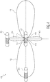
- Figure 4 is a fourth example 400 of an array of wireless communications devices.
- the fourth example 400 shows a first wireless device 402, a second wireless device 404, and a third wireless device 406.
- the first wireless device 402 has a representative antenna pattern 408 with at least four lobes (e.g. two stronger and two weaker).
- the antenna pattern 408 also has a set of nulls 410 at 45, 135, 225 and 315 degrees.
- the wireless devices 402, 404, 406 communicate using near-field solenoid coil antennas.
- the antenna pattern 408 for the solenoid antenna is not circular and instead contains multiple lobes of varying strength as well as null over various angles.
- this lobe and null directionality is further used to reduce interference between neighboring first and third wireless devices 402, 406.
- antenna pattern strength is minimized at the 45, 135, 225 and 315 degree nulls 410. Applied to the airplane use case, interference between diagonally neighboring seats is minimized by these nulls 410. Additional techniques for further shaping the wireless device's antenna patterns can also be used.
- FIG. 5 is a fifth example 500 of an array of wireless communications devices.
- the fifth example 500 includes a first wireless device 502 (e.g. transmitter), a second wireless device 504 (e.g. a first intended receiver) and a third wireless device 506 (e.g. a second unintended receiver).
- a first wireless device 502 e.g. transmitter
- a second wireless device 504 e.g. a first intended receiver
- a third wireless device 506 e.g. a second unintended receiver
- the first wireless device 502 (e.g. transmitter) includes an antenna coil 508 and a signal attenuation device 510 (e.g. passive shield or active electronic attenuator).
- the antenna coil 508 generates a desired antenna pattern 512 and an undesired antenna pattern 514.
- the signal attenuation device 510 helps block the undesired antenna pattern 514 from enabling communication with the third wireless device 506 (e.g. a second unintended receiver).
- the signal attenuation device 510 in one example embodiment is a magnetic shielding sheet placed between the antenna coil 508 and the third wireless device 506 to disable communication with and reduce interference from the third wireless device 506 in a different row of seats, using the airplane cabin use case example again.
- FIG. 6 is an example 600 wireless communication device 602.
- the wireless communication device 602 includes a media processing module 604, a communications control module 606, a transceiver 608, and a presence sensor 610.
- the communications control module 606 includes an enable/disable module 612, a wireless device presence detection module 614, and an object presence detection module 616.
- the wireless device presence detection module 614 is configured to, generate a second wireless device presence signal if a second wireless device (e.g. Figure 4 , 404) is within a preselected range, and generate a third wireless device presence signal if a third wireless device (e.g. Figure 4 , 406) is within the preselected range.
- a second wireless device e.g. Figure 4 , 404
- a third wireless device e.g. Figure 4 , 406
- the communications control module 606 is configured to, enable communication between the wireless device 602 and the second wireless device in response to the second device presence signal, and disable communication between the wireless device 602 and the third wireless device in response to the third device presence signal.
- the wireless devices are configured to be coupled to various user stations, which can be embedded within: an airplane cabin, a theater, a classroom, a hotel lobby, an auditorium, a library, a call-center or a set of office cubicles.
- the wireless devices can also be embedded within a wireless headset, an earbud, a wearable device, or a smartphone.
- the object presence detection module 616 is configured to, generate an object present signal in response to an object coupled to either the first or second wireless device.
- the object in various example embodiments can be: a user, a person, a seat, a desk, a building, or a vehicle.
- the communications control module 606 is configured to, enable communication between the first and second wireless devices in response to both the second device presence signal and the object present signal, and disable communication between the first and second wireless devices if the object present signal is absent.
- the communications control module 606 can be configured to, command the media processing module to play in response to both the second device presence signal and the object present signal, and command the media processing module to pause if the object present signal is absent.
- the communications control module 606 can be configured to, command the media processing module to receive audio in response to both the second device presence signal and the object present signal, and command the media processing module to mute if the object present signal is absent.
- the communications control module 606 can be configured to, command the first wireless device to unlock in response to both the second device presence signal and the object present signal, and command the first wireless device to lock if the object present signal is absent.
- the communications control module 606 can be configured to, command the first wireless device to pair with the second wireless device in response to both the second device presence signal and the object present signal, and command the first wireless device to not pair with the second wireless device if the object present signal is absent.
- the object presence detection module is configured to generate the object present signal in response to the presence sensor receiving from the object at least one of: an optical image, an infra-red image, a radar reflection, a pressure signal, a contact signals, a proximity signal, or a gesture signal.
- the object presence detection module 616 can be configured to generate the object present signal in response to the transceiver 608 receiving from the second wireless device at least one of: a predetermined signal strength, a RFID signal, or an NFC signal.
- wireless device presence detection module 614 the object presence detection module 616, and/or the presence sensor 610
- proximity based communications, pairing, lock/unlock, play/pause and other automatic functions can be enabled between two or more wireless devices.
- Presence/proximity can functionality can be based on: received signal strength indication (RSSI), close-range operation of NFMI, instructing a headset user to bring the headset close to the seatback initially, including a RFID or NFC tag/reader in the wireless devices, radar reflections, face recognition or other camera images, or a user's posture or eye movements (e.g. awake or asleep).
- RSSI received signal strength indication
- close-range operation of NFMI instructing a headset user to bring the headset close to the seatback initially, including a RFID or NFC tag/reader in the wireless devices, radar reflections, face recognition or other camera images, or a user's posture or eye movements (e.g. awake or asleep).
- Auto-play/pause, lock/unlock, etc. enables communications between wireless devices to be paused/stopped when either a headset and/or a user wearing the headset is out of range, even if the wireless device in the headset remains close to the wireless device in the seatback. Audio/video playback can then auto-resume when user either returns and/or places the headset back on their head.
- the set of instructions described above are implemented as functional and software instructions.
- the instructions can be implemented either using logic gates, application specific chips, firmware, as well as other hardware forms.
- Figure 7 is an example system for hosting instructions for enabling the wireless communication device.
- the system 700 shows an input/output data 702 interface with an electronic apparatus 704.
- the electronic apparatus 704 includes a processor 706, a storage device 708, and a non-transient machine-readable storage medium 710.
- the machine-readable storage medium 710 includes instructions 712 which control how the processor 706 receives input data 702 and transforms the input data into output data 702, using data within the storage device 708.
- Example instructions 712 stored in the machine-readable storage medium 710 are discussed elsewhere in this specification.
- the machine-readable storage medium in an alternate example embodiment is a non-transient computer-readable storage medium.
- the processor (such as a central processing unit, CPU, microprocessor, application-specific integrated circuit (ASIC), etc.) controls the overall operation of the storage device (such as random access memory (RAM) for temporary data storage, read only memory (ROM) for permanent data storage, firmware, flash memory, external and internal hard-disk drives, and the like).
- the processor device communicates with the storage device and non-transient machine-readable storage medium using a bus and performs operations and tasks that implement one or more instructions stored in the machine-readable storage medium.
- the machine-readable storage medium in an alternate example embodiment is a computer-readable storage medium.
- Additional Advantages of using near-field (e.g. NFMI, NFEMI, NFC, etc.) signals in various example embodiments include:
- a first wireless device including: a wireless device presence detection module configured to, generate a second wireless device presence signal if a second wireless device is within a preselected range; and generate a third wireless device presence signal if a third wireless device is within the preselected range; and a communications control module, configured to, enable communication between the first and second wireless devices in response to the second device presence signal; and disable communication between the first and third wireless devices in response to the third device presence signal.
Landscapes
- Engineering & Computer Science (AREA)
- Signal Processing (AREA)
- Computer Networks & Wireless Communication (AREA)
- Computer Security & Cryptography (AREA)
- Databases & Information Systems (AREA)
- Mobile Radio Communication Systems (AREA)
- Telephone Function (AREA)
Abstract
Description
- The present specification relates to systems, methods, apparatuses, devices, articles of manufacture and instructions for wireless communication.
- According to an example embodiment, a first wireless device, comprising: a wireless device presence detection module configured to, generate a second wireless device presence signal if a second wireless device is within a preselected range; and generate a third wireless device presence signal if a third wireless device is within the preselected range; and a communications control module, configured to, enable communication between the first and second wireless devices in response to the second device presence signal; and disable communication between the first and third wireless devices in response to the third device presence signal.
- In another example embodiment, further comprising a near-field transceiver configured to limit the preselected range.
- In another example embodiment, the first device is configured to communicate using an antenna pattern having an amplified portion and an attenuated portion; and the amplified portion is aligned toward the second wireless device and the attenuated portion is aligned toward the third wireless device.
- In another example embodiment, the first wireless device includes an antenna having a solenoid shape.
- In another example embodiment, further comprising a shielding structure configured to limit the preselected range.
- In another example embodiment, the shielding structure is configured to attenuate communication signals between the first and third wireless devices.
- In another example embodiment, the first wireless device is configured to communicate with the second wireless devices at a first frequency; and the third wireless device is configured to communicate with a fourth wireless device at a second frequency.
- In another example embodiment, the first and second wireless devices are configured to be coupled to a first user station; and the third wireless device and a fourth wireless device are configured to be coupled to a second user station.
- In another example embodiment, the user stations are embedded within at least one of: an airplane cabin, a theater, a classroom, a hotel lobby, an auditorium, a library, a call-center or a set of office cubicles.
- In another example embodiment, further comprising an object presence detection module configured to, generate an object present signal in response to an object coupled to either the first or second wireless device.
- In another example embodiment, the object is at least one of: a user, a person, a seat, a desk, a building, or a vehicle.
- In another example embodiment, the communications control module, configured to, enable communication between the first and second wireless devices in response to both the second device presence signal and the object present signal; and disable communication between the first and second wireless devices if the object present signal is absent.
- In another example embodiment, further comprising a media processing module; wherein the communications control module, configured to, command the media processing module to play in response to both the second device presence signal and the object present signal; and command the media processing module to pause if the object present signal is absent.
- In another example embodiment, further comprising a media processing module; wherein the communications control module, configured to, command the media processing module to receive audio in response to both the second device presence signal and the object present signal; and command the media processing module to mute if the object present signal is absent.
- In another example embodiment, further comprising a media processing module; wherein the communications control module, configured to, command the first wireless device to unlock in response to both the second device presence signal and the object present signal; and command the first wireless device to lock if the object present signal is absent.
- In another example embodiment, further comprising a media processing module; wherein the communications control module, configured to, command the first wireless device to pair with the second wireless device in response to both the second device presence signal and the object present signal; and command the first wireless device to not pair with the second wireless device if the object present signal is absent.
- In another example embodiment, further comprising a presence sensor coupled to the object presence detection module; wherein the object presence detection module is configured to generate the object present signal in response to the presence sensor receiving from the object at least one of: an optical image, an infra-red image, a radar reflection, a pressure signal, a contact signals, a proximity signal, or a gesture signal.
- In another example embodiment, the object presence detection module is configured to generate the object present signal in response to the transceiver receiving from the second wireless device at least one of: a predetermined signal strength, a RFID signal, or an NFC signal.
- According to an example embodiment, an article of manufacture including at least one non-transitory, tangible machine readable storage medium containing executable machine instructions for wireless communication, comprising: wherein the article includes a first wireless device, a wireless device presence detection module, and a communications control module; wherein the instructions include, generate a second wireless device presence signal if a second wireless device is within a preselected range; generate a third wireless device presence signal if a third wireless device is within the preselected range; enable communication between the first and second wireless devices in response to the second device presence signal; and disable communication between the first and third wireless devices in response to the third device presence signal.
- According to an example embodiment, a method for enabling a first wireless device to be operated, comprising: distributing a set of instructions, stored on a non-transitory, tangible computer readable storage medium, for configuring the first wireless device; wherein the first wireless device includes a wireless device presence detection module and a communications control module; and wherein the instructions include, generate a second wireless device presence signal if a second wireless device is within a preselected range; generate a third wireless device presence signal if a third wireless device is within the preselected range; enable communication between the first and second wireless devices in response to the second device presence signal; and disable communication between the first and third wireless devices in response to the third device presence signal.
- In another example embodiment, further comprising a media processing module; wherein the communications control module, configured to, command the media processing module to play in response to the second device presence signal; and command the media processing module to pause if the second device presence signal is absent.
- In another example embodiment, further comprising a media processing module; wherein the communications control module, configured to, command the media processing module to receive audio in response to the second device presence signal; and command the media processing module to mute if the second device presence signal is absent.
- In another example embodiment, further comprising a media processing module; wherein the communications control module, configured to, command the first wireless device to unlock in response to the second device presence signal; and command the first wireless device to lock if the second device presence signal is absent.
- In another example embodiment, further comprising a media processing module; wherein the communications control module, configured to, command the first wireless device to pair with the second wireless device in response to the second device presence signal; and command the first wireless device to not pair with the second wireless device if the second device presence signal is absent.
- The above discussion is not intended to represent every example embodiment or every implementation within the scope of the current or future Claim sets. The Figures and Detailed Description that follow also exemplify various example embodiments.
- Various example embodiments may be more completely understood in consideration of the following Detailed Description in connection with the accompanying Drawings, in which:
-
-
Figure 1 is a first example of an array of wireless communications devices. -
Figure 2 is a second example of an array of wireless communications devices. -
Figure 3 is a third example of an array of wireless communications devices. -
Figure 4 is a fourth example of an array of wireless communications devices. -
Figure 5 is a fifth example of an array of wireless communications devices. -
Figure 6 is an example wireless communication device. -
Figure 7 is an example system for hosting instructions for enabling the wireless communication device. - While the disclosure is amenable to various modifications and alternative forms, specifics thereof have been shown by way of example in the drawings and will be described in detail. It should be understood, however, that other embodiments, beyond the particular embodiments described, are possible as well. All modifications, equivalents, and alternative embodiments falling within the spirit and scope of the appended claims are covered as well.
- Communication with and/or between a pair of specific devices in a confined geometric space can be challenging. For example, multiple separate media transmissions between pairs of devices in an airplane cabin use a physical wire connection between the pair of devices (e.g. an entertainment media player in a back of an airline seat and a passenger's wired headset) to ensure exclusivity of communications.
- Switching such headphones to wireless to increase an airline passenger's comfort level using far-field technologies such as Bluetooth, wireless and/or cellular signals, however, may result in an unacceptable interference either with other passengers and/or other electronic devices and thus be prohibited.
- Also, RF signals in an enclosed space such as an airplane must be absorbed by something, like human tissue as characterized by its Specific absorption rate (SAR). SAR is a measure of the rate at which energy is absorbed by the human body when exposed to a radio frequency (RF) electromagnetic field. Thus too many far-field RF devices in such a space means a greater exposure to radiation.
- For example, in some applications RF interference generated by multiple close-proximity far-field signals would be high (e.g. wireless signals in an airplane cabin interfering with the airplane's avionics, communications or other systems).
- In addition, due to a proximity of many other passengers, RF systems such as Bluetooth could break down due to an elevated level of mutual interference (e.g. Bluetooth Classic has only 80 channels, but has a range of 10-15 meters). Bluetooth devices could conflict with more than 80 users in various crowded spaces such as an airplane, theater, classroom, hotel lobby, auditorium, call-center, office cubicles, etc.
- Even with less than 80 users, degradation may occur as the channels are not guaranteed to be used in mutually exclusive timeslots as the various Bluetooth systems (= transmitter + receiver) are not time synchronized and will randomly overlap in time on the same channel and will disturb each other.
- As a result, media (e.g. audio, video, etc.) connection interference and/or lost connections will result in a bad user experience.
-
Figure 1 is a first example 100 of an array of wireless communications devices. In the first example 100 the array of wireless communications devices (e.g. in an airplane cabin, theater, classroom, etc.) are arranged intorows 104 andcolumns 106. - Shown is a first wireless device 108 (e.g. integrated into an airplane seatback) and a second wireless device 110 (e.g. embedded in a user headset). Due to their relatively close proximity, these
devices - Thus in for example an airplane cabin, the far-field signals between wireless devices in seatbacks and wireless devices in passenger headsets, all sitting closely together, substantially overlap, thereby interfering with not only other passenger communications but perhaps also the airplane communications and other systems mentioned.
-
Figure 2 is a second example 200 of an array of wireless communications devices. In the second example 200 the array of wireless communications devices are also arranged inrows 204 andcolumns 206. - Similarly shown, a first wireless device 208 (e.g. integrated into a seatback) and a second wireless device 210 (e.g. embedded in a user headset). In this example however a wireless device signal range 212 of the
devices - This is because in the second example 200, the
wireless devices wireless devices - Antenna size and pattern at either or both the transmitter and receiver side as well as the transmit power and/or receive sensitivity can be adjusted. Tight control over the signal range reduces an overall number of potentially interfering wireless devices and increases a robustness of the overall communications system with the array of devices. Thus, an amount of interference between neighboring pairs of wireless devices is substantially reduced.
-
Figure 3 is a third example 300 of an array of wireless communications devices. In the third example 300 the array of wireless communications devices arranged intorows 304 andcolumns 306 includes a set of near-field wireless devices having a set of near-field wireless device signal ranges, as shown, however each pair of wireless devices (e.g. in a seatback and user headset) uses a different communications frequency/channel. - Interference between neighboring wireless devices is further reduced using the different carrier frequencies between a set of nearest neighboring (e.g. adjacent) pairs of wireless devices in the array. In this frequency reuse example, carrier frequencies f1, f2, f3 and f4 are used as shown in
Figure 3 . -
Figure 4 is a fourth example 400 of an array of wireless communications devices. The fourth example 400 shows afirst wireless device 402, asecond wireless device 404, and athird wireless device 406. Thefirst wireless device 402 has arepresentative antenna pattern 408 with at least four lobes (e.g. two stronger and two weaker). Theantenna pattern 408 also has a set ofnulls 410 at 45, 135, 225 and 315 degrees. - In example 400, the
wireless devices antenna pattern 408 for the solenoid antenna is not circular and instead contains multiple lobes of varying strength as well as null over various angles. - In some example embodiments, this lobe and null directionality is further used to reduce interference between neighboring first and
third wireless devices nulls 410. Additional techniques for further shaping the wireless device's antenna patterns can also be used. -
Figure 5 is a fifth example 500 of an array of wireless communications devices. The fifth example 500 includes a first wireless device 502 (e.g. transmitter), a second wireless device 504 (e.g. a first intended receiver) and a third wireless device 506 (e.g. a second unintended receiver). - The first wireless device 502 (e.g. transmitter) includes an
antenna coil 508 and a signal attenuation device 510 (e.g. passive shield or active electronic attenuator). Theantenna coil 508 generates a desiredantenna pattern 512 and anundesired antenna pattern 514. Thesignal attenuation device 510 helps block theundesired antenna pattern 514 from enabling communication with the third wireless device 506 (e.g. a second unintended receiver). - The
signal attenuation device 510 in one example embodiment is a magnetic shielding sheet placed between theantenna coil 508 and thethird wireless device 506 to disable communication with and reduce interference from thethird wireless device 506 in a different row of seats, using the airplane cabin use case example again. -
Figure 6 is an example 600wireless communication device 602. Thewireless communication device 602 includes amedia processing module 604, acommunications control module 606, atransceiver 608, and apresence sensor 610. Thecommunications control module 606 includes an enable/disablemodule 612, a wireless devicepresence detection module 614, and an objectpresence detection module 616. - The wireless device
presence detection module 614 is configured to, generate a second wireless device presence signal if a second wireless device (e.g.Figure 4 , 404) is within a preselected range, and generate a third wireless device presence signal if a third wireless device (e.g.Figure 4 , 406) is within the preselected range. - The
communications control module 606 is configured to, enable communication between thewireless device 602 and the second wireless device in response to the second device presence signal, and disable communication between thewireless device 602 and the third wireless device in response to the third device presence signal. - In some example embodiments, the wireless devices are configured to be coupled to various user stations, which can be embedded within: an airplane cabin, a theater, a classroom, a hotel lobby, an auditorium, a library, a call-center or a set of office cubicles. The wireless devices can also be embedded within a wireless headset, an earbud, a wearable device, or a smartphone.
- The object
presence detection module 616 is configured to, generate an object present signal in response to an object coupled to either the first or second wireless device. The object in various example embodiments can be: a user, a person, a seat, a desk, a building, or a vehicle. - In one example, the
communications control module 606 is configured to, enable communication between the first and second wireless devices in response to both the second device presence signal and the object present signal, and disable communication between the first and second wireless devices if the object present signal is absent. - In example embodiments which further include the
media processing module 604, thecommunications control module 606 can be configured to, command the media processing module to play in response to both the second device presence signal and the object present signal, and command the media processing module to pause if the object present signal is absent. - In other example embodiments, the
communications control module 606 can be configured to, command the media processing module to receive audio in response to both the second device presence signal and the object present signal, and command the media processing module to mute if the object present signal is absent. - In still other example embodiments, the
communications control module 606 can be configured to, command the first wireless device to unlock in response to both the second device presence signal and the object present signal, and command the first wireless device to lock if the object present signal is absent. - Also in other example embodiments, the
communications control module 606 can be configured to, command the first wireless device to pair with the second wireless device in response to both the second device presence signal and the object present signal, and command the first wireless device to not pair with the second wireless device if the object present signal is absent. - In example embodiments where the
wireless communication device 602 includes apresence sensor 610 coupled to the objectpresence detection module 616, the object presence detection module is configured to generate the object present signal in response to the presence sensor receiving from the object at least one of: an optical image, an infra-red image, a radar reflection, a pressure signal, a contact signals, a proximity signal, or a gesture signal. - Alternatively, the object
presence detection module 616 can be configured to generate the object present signal in response to thetransceiver 608 receiving from the second wireless device at least one of: a predetermined signal strength, a RFID signal, or an NFC signal. - Thus, using the wireless device
presence detection module 614, the objectpresence detection module 616, and/or thepresence sensor 610, proximity based communications, pairing, lock/unlock, play/pause and other automatic functions can be enabled between two or more wireless devices. - Presence/proximity can functionality can be based on: received signal strength indication (RSSI), close-range operation of NFMI, instructing a headset user to bring the headset close to the seatback initially, including a RFID or NFC tag/reader in the wireless devices, radar reflections, face recognition or other camera images, or a user's posture or eye movements (e.g. awake or asleep).
- Auto-play/pause, lock/unlock, etc. enables communications between wireless devices to be paused/stopped when either a headset and/or a user wearing the headset is out of range, even if the wireless device in the headset remains close to the wireless device in the seatback. Audio/video playback can then auto-resume when user either returns and/or places the headset back on their head.
- The instructions discussed above can be executed in any order, unless a specific order is explicitly stated. Also, those skilled in the art will recognize that while one example set of instructions/method has been discussed, the material in this specification can be combined in a variety of ways to yield other examples as well, and are to be understood within a context provided by this detailed description.
- In some example embodiments, the set of instructions described above are implemented as functional and software instructions. In other embodiments, the instructions can be implemented either using logic gates, application specific chips, firmware, as well as other hardware forms.
-
Figure 7 is an example system for hosting instructions for enabling the wireless communication device. Thesystem 700 shows an input/output data 702 interface with anelectronic apparatus 704. Theelectronic apparatus 704 includes aprocessor 706, astorage device 708, and a non-transient machine-readable storage medium 710. The machine-readable storage medium 710 includesinstructions 712 which control how theprocessor 706 receivesinput data 702 and transforms the input data intooutput data 702, using data within thestorage device 708.Example instructions 712 stored in the machine-readable storage medium 710 are discussed elsewhere in this specification. The machine-readable storage medium in an alternate example embodiment is a non-transient computer-readable storage medium. - The processor (such as a central processing unit, CPU, microprocessor, application-specific integrated circuit (ASIC), etc.) controls the overall operation of the storage device (such as random access memory (RAM) for temporary data storage, read only memory (ROM) for permanent data storage, firmware, flash memory, external and internal hard-disk drives, and the like). The processor device communicates with the storage device and non-transient machine-readable storage medium using a bus and performs operations and tasks that implement one or more instructions stored in the machine-readable storage medium. The machine-readable storage medium in an alternate example embodiment is a computer-readable storage medium.
- Additional Advantages of using near-field (e.g. NFMI, NFEMI, NFC, etc.) signals in various example embodiments include:
- a. Ultra-low power: NFMI audio transmission and reception only requires ∼3mW of power consumption which is substantially lower than Bluetooth Classic solutions which today typically require 50-60 mW of power.
- b. Using NFMI a high-quality stereo stream can be received, requiring only ∼5mW of power consumption which is a factor 10 lower than a typical Bluetooth headphone. This implies that the battery lifetime of a wireless headphone will be drastically improved.
- c. This means that a headset does not need to be recharged during the duration of a long flight (e.g. airplane use case example), which significantly reduces the burden on both crew and maintenance personnel to ensure that all headphones are operational throughout the flight.
- d. Additionally, it does not require the passenger to recharge the headphones himself during the flight, potentially removing the need to add a charging station to each seat.
- e. Potentially the headphones can be recharged using wireless charging, in which case it is possible to reuse the NFMI coil for wireless charging. Adding wireless charging again simplifies the maintenance problem for crew and/or maintenance personnel.
- f. Additionally, NFMI can be used for close-range communications in situations where the number of devices is limited. This includes:
- i. Gaming headsets: gamers typically sit close to their screen so NFMI provides a good technology for audio transport.
- ii. PC headsets: similarly, when working on a PC or laptop, users are in close proximity to their screen and NFMI can be used for audio transport.
- iii. Direct conversation between persons in noisy situations (e.g. firefighters, construction workers, airport ground handlers, motorcyclists): by wearing headsets and coming close, they can have a natural conversation using NFMI, whereby the noise is removed by capturing and processing the microphone signals at the first person's headset and playing them back in the other person's headset.
- Additionally:
- g. In some example embodiments, the wireless devices can be mobile, such as those carried by various people who first come in close proximity to pair their wireless devices and then disperse but continue their conversation.
- h. Robust communication is supported despite close co-location of multiple users due to the close range and antenna pattern shaping capabilities of NFMI.
- i. Localized, intuitive communication is enabled since a wireless communication channel is automatically established once the user comes in range without the need for any formal pairing or manual set up.
- j. Automatic pairing is possible since the cumbersome process of Bluetooth pairing can be completely avoided by using NFMI and proximity pairing. By coming close to the other device, communication will automatically be established without user intervention.
- One example discloses a first wireless device, including: a wireless device presence detection module configured to, generate a second wireless device presence signal if a second wireless device is within a preselected range; and generate a third wireless device presence signal if a third wireless device is within the preselected range; and a communications control module, configured to, enable communication between the first and second wireless devices in response to the second device presence signal; and disable communication between the first and third wireless devices in response to the third device presence signal.
- It will be readily understood that the components of the embodiments as generally described herein and illustrated in the appended figures could be arranged and designed in a wide variety of different configurations. Thus, the detailed description of various embodiments, as represented in the figures, is not intended to limit the scope of the present disclosure, but is merely representative of various embodiments. While the various aspects of the embodiments are presented in drawings, the drawings are not necessarily drawn to scale unless specifically indicated.
- The present invention may be embodied in other specific forms without departing from its spirit or essential characteristics. The described embodiments are to be considered in all respects only as illustrative and not restrictive. The scope of the invention is, therefore, indicated by the appended claims rather than by this detailed description. All changes which come within the meaning and range of equivalency of the claims are to be embraced within their scope.
- Reference throughout this specification to features, advantages, or similar language does not imply that all of the features and advantages that may be realized with the present invention should be or are in any single embodiment of the invention. Rather, language referring to the features and advantages is understood to mean that a specific feature, advantage, or characteristic described in connection with an embodiment is included in at least one embodiment of the present invention. Thus, discussions of the features and advantages, and similar language, throughout this specification may, but do not necessarily, refer to the same embodiment.
- Furthermore, the described features, advantages, and characteristics of the invention may be combined in any suitable manner in one or more embodiments. One skilled in the relevant art will recognize, in light of the description herein, that the invention can be practiced without one or more of the specific features or advantages of a particular embodiment. In other instances, additional features and advantages may be recognized in certain embodiments that may not be present in all embodiments of the invention.
- Reference throughout this specification to "one embodiment," "an embodiment," or similar language means that a particular feature, structure, or characteristic described in connection with the indicated embodiment is included in at least one embodiment of the present invention. Thus, the phrases "in one embodiment," "in an embodiment," and similar language throughout this specification may, but do not necessarily, all refer to the same embodiment.
Claims (15)
- A first wireless device, comprising:a wireless device presence detection module configured to,generate a second wireless device presence signal if a second wireless device is within a preselected range; andgenerate a third wireless device presence signal if a third wireless device is within the preselected range; anda communications control module, configured to,enable communication between the first and second wireless devices in response to the second device presence signal; anddisable communication between the first and third wireless devices in response to the third device presence signal.
- The device of claim 1:further comprising a near-field transceiver configured to limit the preselected range.
- The device of claim 1 or 2:wherein the first device is configured to communicate using an antenna pattern having an amplified portion and an attenuated portion; andwherein the amplified portion is aligned toward the second wireless device and the attenuated portion is aligned toward the third wireless device.
- The device of any preceding claim:wherein the first wireless device includes an antenna having a solenoid shape.
- The device of any preceding claim:further comprising a shielding structure configured to limit the preselected range.
- The device of claim 5:wherein the shielding structure is configured to attenuate communication signals between the first and third wireless devices.
- The device of any preceding claim:wherein the first wireless device is configured to communicate with the second wireless devices at a first frequency; andwherein the third wireless device is configured to communicate with a fourth wireless device at a second frequency.
- The device of any preceding claim:wherein the first and second wireless devices are configured to be coupled to a first user station; andwherein the third wireless device and a fourth wireless device are configured to be coupled to a second user station.
- The device of claim 8:wherein the user stations are embedded within at least one of: an airplane cabin, a theater, a classroom, a hotel lobby, an auditorium, a library, a call-center or a set of office cubicles.
- The device of any preceding claim, further comprising:an object presence detection module configured to, generate an object present signal in response to an object coupled to either the first or second wireless device.
- The device of claim 10:wherein the object is at least one of: a user, a person, a seat, a desk, a building, or a vehicle.
- The device of claim 10 or 11:wherein the communications control module, configured to,enable communication between the first and second wireless devices in response to both the second device presence signal and the object present signal; anddisable communication between the first and second wireless devices if the object present signal is absent.
- The device of any of claims 10 to 12:further comprising a media processing module;wherein the communications control module, configured to,command the media processing module to play in response to both the second device presence signal and the object present signal; andcommand the media processing module to pause if the object present signal is absent.
- The device of any of claims claim 10 to 13:further comprising a media processing module;wherein the communications control module, configured to,command the media processing module to receive audio in response to both the second device presence signal and the object present signal; andcommand the media processing module to mute if the object present signal is absent.
- The device of any of claims 10 to 14:further comprising a media processing module;wherein the communications control module, configured to,command the first wireless device to unlock in response to both the second device presence signal and the object present signal; andcommand the first wireless device to lock if the object present signal is absent.
Applications Claiming Priority (1)
| Application Number | Priority Date | Filing Date | Title |
|---|---|---|---|
| US15/862,231 US10616750B2 (en) | 2018-01-04 | 2018-01-04 | Wireless communication device |
Publications (2)
| Publication Number | Publication Date |
|---|---|
| EP3509389A1 true EP3509389A1 (en) | 2019-07-10 |
| EP3509389B1 EP3509389B1 (en) | 2022-10-19 |
Family
ID=65003095
Family Applications (1)
| Application Number | Title | Priority Date | Filing Date |
|---|---|---|---|
| EP18213197.9A Active EP3509389B1 (en) | 2018-01-04 | 2018-12-17 | Wireless communication device |
Country Status (3)
| Country | Link |
|---|---|
| US (1) | US10616750B2 (en) |
| EP (1) | EP3509389B1 (en) |
| CN (1) | CN110012452B (en) |
Families Citing this family (4)
| Publication number | Priority date | Publication date | Assignee | Title |
|---|---|---|---|---|
| GB2593455B (en) * | 2020-03-18 | 2024-05-15 | Sonos Scotland Ltd | Improvements in or relating to wireless media systems |
| US20210376881A1 (en) * | 2020-05-29 | 2021-12-02 | Shure Acquisition Holdings, Inc. | Wearable Device With Conductive Coil for Wireless Charging and Communicating |
| JP7830221B2 (en) * | 2022-04-28 | 2026-03-16 | 株式会社東芝 | Inspection system |
| US12167050B2 (en) * | 2022-05-13 | 2024-12-10 | Citrix Systems, Inc. | Proximity and context based stream playback control |
Citations (4)
| Publication number | Priority date | Publication date | Assignee | Title |
|---|---|---|---|---|
| US20030100274A1 (en) * | 2001-11-28 | 2003-05-29 | Sendo International Limited | Wireless Headset-Based Communication |
| WO2008113053A1 (en) * | 2007-03-14 | 2008-09-18 | Qualcomm Incorporated | Headset having wirelessly linked earpieces |
| WO2012021879A2 (en) * | 2010-08-13 | 2012-02-16 | Interdigital Patent Holdings, Inc. | Methods and systems for in-device interference mitigation |
| WO2017100821A1 (en) * | 2015-12-17 | 2017-06-22 | Lyrebird Interactive Holdings Pty Ltd | Apparatus and method for an interactive entertainment media device |
Family Cites Families (11)
| Publication number | Priority date | Publication date | Assignee | Title |
|---|---|---|---|---|
| US6701158B2 (en) * | 2001-12-19 | 2004-03-02 | R. Edward Moreth | Use controller for a wireless communication device |
| US8946939B2 (en) * | 2011-03-31 | 2015-02-03 | Qualcomm Incorporated | Systems and methods for detecting and protecting a wireless power communication device in a wireless power system |
| US9559790B2 (en) * | 2012-01-30 | 2017-01-31 | Keyssa, Inc. | Link emission control |
| CN203180922U (en) | 2012-12-19 | 2013-09-04 | 厦门莱亚特医疗器械有限公司 | Wireless earphone system based on near field electromagnetic induction |
| US9265090B2 (en) * | 2013-06-14 | 2016-02-16 | Netgear, Inc. | Alignment of packets for implementing coexistence of multiple homogeneous radios |
| US9820095B2 (en) * | 2014-04-02 | 2017-11-14 | Sony Corporation | Power efficient proximity detection |
| US9843360B2 (en) * | 2014-08-14 | 2017-12-12 | Sony Corporation | Method and system for use in configuring multiple near field antenna systems |
| US9560050B2 (en) * | 2014-09-08 | 2017-01-31 | At&T Intellectual Property I, L.P | System and method to share a resource or a capability of a device |
| US9866966B2 (en) | 2015-05-20 | 2018-01-09 | Fender Musical Instruments Corporation | Wireless audio system |
| US9859728B2 (en) * | 2015-09-01 | 2018-01-02 | Dell Products, Lp | System for securing a wireless power pad |
| CN105792049B (en) | 2016-04-11 | 2019-09-10 | 富士高实业有限公司 | Pure wireless earphone adopting optimal monopole antenna |
-
2018
- 2018-01-04 US US15/862,231 patent/US10616750B2/en active Active
- 2018-12-17 EP EP18213197.9A patent/EP3509389B1/en active Active
-
2019
- 2019-01-02 CN CN201910003116.3A patent/CN110012452B/en active Active
Patent Citations (4)
| Publication number | Priority date | Publication date | Assignee | Title |
|---|---|---|---|---|
| US20030100274A1 (en) * | 2001-11-28 | 2003-05-29 | Sendo International Limited | Wireless Headset-Based Communication |
| WO2008113053A1 (en) * | 2007-03-14 | 2008-09-18 | Qualcomm Incorporated | Headset having wirelessly linked earpieces |
| WO2012021879A2 (en) * | 2010-08-13 | 2012-02-16 | Interdigital Patent Holdings, Inc. | Methods and systems for in-device interference mitigation |
| WO2017100821A1 (en) * | 2015-12-17 | 2017-06-22 | Lyrebird Interactive Holdings Pty Ltd | Apparatus and method for an interactive entertainment media device |
Also Published As
| Publication number | Publication date |
|---|---|
| US10616750B2 (en) | 2020-04-07 |
| US20190208396A1 (en) | 2019-07-04 |
| CN110012452B (en) | 2024-10-18 |
| EP3509389B1 (en) | 2022-10-19 |
| CN110012452A (en) | 2019-07-12 |
Similar Documents
| Publication | Publication Date | Title |
|---|---|---|
| EP3509389B1 (en) | Wireless communication device | |
| EP3469809B1 (en) | Wireless headset | |
| US11894604B2 (en) | Communication apparatus | |
| Venugopal et al. | Millimeter wave networked wearables in dense indoor environments | |
| EP2498514A1 (en) | A hearing device and methods of operating a hearing device | |
| US6735438B1 (en) | Antenna for air-to-ground communication | |
| US20210385893A1 (en) | Communication method between multi devices in bluetooth communication environment and electronic device therefor | |
| US20190297585A1 (en) | Density optimized bluetooth antenna | |
| Chen et al. | Downlink performance analysis of intelligent reflecting surface-enabled networks | |
| CN114616765A (en) | Network side device, terminal side device, communication method, communication apparatus, and medium | |
| US20230112073A1 (en) | Electronic device for controlling ambient sound based on audio scene and operating method thereof | |
| US12363519B2 (en) | Apparatus and method for establishing a connection | |
| US11974107B2 (en) | Electronic device and method for audio sharing using the same | |
| US10916830B2 (en) | Earbud system | |
| CN108985267A (en) | Auditorium identity scene identification system | |
| US10965334B2 (en) | SAR radiation-free mobile terminal body, SAR radiation-free external communication body and SAR radiation-free mobile terminal | |
| KR101778528B1 (en) | Method and apparatus for transmitting of communication terminal having antenna | |
| KR20210100198A (en) | Electronic equipment having an antenna | |
| EP3130082A1 (en) | Improvement in, or relating to, passenger entertainment systems | |
| JP2012044375A (en) | Radio communication system and radio communication method | |
| US10277316B1 (en) | Free space optical headset | |
| CN111095968A (en) | Information processing method and device and communication equipment | |
| CN117579114A (en) | Brain-computer wireless communication transmission system | |
| CN113994610B (en) | Method and apparatus for a low power communication link between wireless devices | |
| Joumessi-Demeffo et al. | A link reliability study of optical wireless headset inside aircraft cockpit |
Legal Events
| Date | Code | Title | Description |
|---|---|---|---|
| PUAI | Public reference made under article 153(3) epc to a published international application that has entered the european phase |
Free format text: ORIGINAL CODE: 0009012 |
|
| STAA | Information on the status of an ep patent application or granted ep patent |
Free format text: STATUS: THE APPLICATION HAS BEEN PUBLISHED |
|
| AK | Designated contracting states |
Kind code of ref document: A1 Designated state(s): AL AT BE BG CH CY CZ DE DK EE ES FI FR GB GR HR HU IE IS IT LI LT LU LV MC MK MT NL NO PL PT RO RS SE SI SK SM TR |
|
| AX | Request for extension of the european patent |
Extension state: BA ME |
|
| STAA | Information on the status of an ep patent application or granted ep patent |
Free format text: STATUS: REQUEST FOR EXAMINATION WAS MADE |
|
| 17P | Request for examination filed |
Effective date: 20200110 |
|
| RBV | Designated contracting states (corrected) |
Designated state(s): AL AT BE BG CH CY CZ DE DK EE ES FI FR GB GR HR HU IE IS IT LI LT LU LV MC MK MT NL NO PL PT RO RS SE SI SK SM TR |
|
| STAA | Information on the status of an ep patent application or granted ep patent |
Free format text: STATUS: EXAMINATION IS IN PROGRESS |
|
| 17Q | First examination report despatched |
Effective date: 20210204 |
|
| GRAP | Despatch of communication of intention to grant a patent |
Free format text: ORIGINAL CODE: EPIDOSNIGR1 |
|
| STAA | Information on the status of an ep patent application or granted ep patent |
Free format text: STATUS: GRANT OF PATENT IS INTENDED |
|
| INTG | Intention to grant announced |
Effective date: 20220323 |
|
| GRAJ | Information related to disapproval of communication of intention to grant by the applicant or resumption of examination proceedings by the epo deleted |
Free format text: ORIGINAL CODE: EPIDOSDIGR1 |
|
| STAA | Information on the status of an ep patent application or granted ep patent |
Free format text: STATUS: EXAMINATION IS IN PROGRESS |
|
| INTC | Intention to grant announced (deleted) | ||
| GRAP | Despatch of communication of intention to grant a patent |
Free format text: ORIGINAL CODE: EPIDOSNIGR1 |
|
| STAA | Information on the status of an ep patent application or granted ep patent |
Free format text: STATUS: GRANT OF PATENT IS INTENDED |
|
| GRAS | Grant fee paid |
Free format text: ORIGINAL CODE: EPIDOSNIGR3 |
|
| GRAA | (expected) grant |
Free format text: ORIGINAL CODE: 0009210 |
|
| STAA | Information on the status of an ep patent application or granted ep patent |
Free format text: STATUS: THE PATENT HAS BEEN GRANTED |
|
| INTG | Intention to grant announced |
Effective date: 20220906 |
|
| AK | Designated contracting states |
Kind code of ref document: B1 Designated state(s): AL AT BE BG CH CY CZ DE DK EE ES FI FR GB GR HR HU IE IS IT LI LT LU LV MC MK MT NL NO PL PT RO RS SE SI SK SM TR |
|
| REG | Reference to a national code |
Ref country code: GB Ref legal event code: FG4D |
|
| REG | Reference to a national code |
Ref country code: CH Ref legal event code: EP |
|
| REG | Reference to a national code |
Ref country code: IE Ref legal event code: FG4D |
|
| REG | Reference to a national code |
Ref country code: DE Ref legal event code: R096 Ref document number: 602018041922 Country of ref document: DE |
|
| REG | Reference to a national code |
Ref country code: AT Ref legal event code: REF Ref document number: 1526361 Country of ref document: AT Kind code of ref document: T Effective date: 20221115 |
|
| REG | Reference to a national code |
Ref country code: LT Ref legal event code: MG9D |
|
| REG | Reference to a national code |
Ref country code: NL Ref legal event code: MP Effective date: 20221019 |
|
| REG | Reference to a national code |
Ref country code: AT Ref legal event code: MK05 Ref document number: 1526361 Country of ref document: AT Kind code of ref document: T Effective date: 20221019 |
|
| PG25 | Lapsed in a contracting state [announced via postgrant information from national office to epo] |
Ref country code: NL Free format text: LAPSE BECAUSE OF FAILURE TO SUBMIT A TRANSLATION OF THE DESCRIPTION OR TO PAY THE FEE WITHIN THE PRESCRIBED TIME-LIMIT Effective date: 20221019 |
|
| PG25 | Lapsed in a contracting state [announced via postgrant information from national office to epo] |
Ref country code: SE Free format text: LAPSE BECAUSE OF FAILURE TO SUBMIT A TRANSLATION OF THE DESCRIPTION OR TO PAY THE FEE WITHIN THE PRESCRIBED TIME-LIMIT Effective date: 20221019 Ref country code: PT Free format text: LAPSE BECAUSE OF FAILURE TO SUBMIT A TRANSLATION OF THE DESCRIPTION OR TO PAY THE FEE WITHIN THE PRESCRIBED TIME-LIMIT Effective date: 20230220 Ref country code: NO Free format text: LAPSE BECAUSE OF FAILURE TO SUBMIT A TRANSLATION OF THE DESCRIPTION OR TO PAY THE FEE WITHIN THE PRESCRIBED TIME-LIMIT Effective date: 20230119 Ref country code: LT Free format text: LAPSE BECAUSE OF FAILURE TO SUBMIT A TRANSLATION OF THE DESCRIPTION OR TO PAY THE FEE WITHIN THE PRESCRIBED TIME-LIMIT Effective date: 20221019 Ref country code: FI Free format text: LAPSE BECAUSE OF FAILURE TO SUBMIT A TRANSLATION OF THE DESCRIPTION OR TO PAY THE FEE WITHIN THE PRESCRIBED TIME-LIMIT Effective date: 20221019 Ref country code: ES Free format text: LAPSE BECAUSE OF FAILURE TO SUBMIT A TRANSLATION OF THE DESCRIPTION OR TO PAY THE FEE WITHIN THE PRESCRIBED TIME-LIMIT Effective date: 20221019 Ref country code: AT Free format text: LAPSE BECAUSE OF FAILURE TO SUBMIT A TRANSLATION OF THE DESCRIPTION OR TO PAY THE FEE WITHIN THE PRESCRIBED TIME-LIMIT Effective date: 20221019 |
|
| PG25 | Lapsed in a contracting state [announced via postgrant information from national office to epo] |
Ref country code: RS Free format text: LAPSE BECAUSE OF FAILURE TO SUBMIT A TRANSLATION OF THE DESCRIPTION OR TO PAY THE FEE WITHIN THE PRESCRIBED TIME-LIMIT Effective date: 20221019 Ref country code: PL Free format text: LAPSE BECAUSE OF FAILURE TO SUBMIT A TRANSLATION OF THE DESCRIPTION OR TO PAY THE FEE WITHIN THE PRESCRIBED TIME-LIMIT Effective date: 20221019 Ref country code: LV Free format text: LAPSE BECAUSE OF FAILURE TO SUBMIT A TRANSLATION OF THE DESCRIPTION OR TO PAY THE FEE WITHIN THE PRESCRIBED TIME-LIMIT Effective date: 20221019 Ref country code: IS Free format text: LAPSE BECAUSE OF FAILURE TO SUBMIT A TRANSLATION OF THE DESCRIPTION OR TO PAY THE FEE WITHIN THE PRESCRIBED TIME-LIMIT Effective date: 20230219 Ref country code: HR Free format text: LAPSE BECAUSE OF FAILURE TO SUBMIT A TRANSLATION OF THE DESCRIPTION OR TO PAY THE FEE WITHIN THE PRESCRIBED TIME-LIMIT Effective date: 20221019 Ref country code: GR Free format text: LAPSE BECAUSE OF FAILURE TO SUBMIT A TRANSLATION OF THE DESCRIPTION OR TO PAY THE FEE WITHIN THE PRESCRIBED TIME-LIMIT Effective date: 20230120 |
|
| REG | Reference to a national code |
Ref country code: DE Ref legal event code: R097 Ref document number: 602018041922 Country of ref document: DE |
|
| PG25 | Lapsed in a contracting state [announced via postgrant information from national office to epo] |
Ref country code: SM Free format text: LAPSE BECAUSE OF FAILURE TO SUBMIT A TRANSLATION OF THE DESCRIPTION OR TO PAY THE FEE WITHIN THE PRESCRIBED TIME-LIMIT Effective date: 20221019 Ref country code: RO Free format text: LAPSE BECAUSE OF FAILURE TO SUBMIT A TRANSLATION OF THE DESCRIPTION OR TO PAY THE FEE WITHIN THE PRESCRIBED TIME-LIMIT Effective date: 20221019 Ref country code: EE Free format text: LAPSE BECAUSE OF FAILURE TO SUBMIT A TRANSLATION OF THE DESCRIPTION OR TO PAY THE FEE WITHIN THE PRESCRIBED TIME-LIMIT Effective date: 20221019 Ref country code: DK Free format text: LAPSE BECAUSE OF FAILURE TO SUBMIT A TRANSLATION OF THE DESCRIPTION OR TO PAY THE FEE WITHIN THE PRESCRIBED TIME-LIMIT Effective date: 20221019 Ref country code: CZ Free format text: LAPSE BECAUSE OF FAILURE TO SUBMIT A TRANSLATION OF THE DESCRIPTION OR TO PAY THE FEE WITHIN THE PRESCRIBED TIME-LIMIT Effective date: 20221019 |
|
| REG | Reference to a national code |
Ref country code: CH Ref legal event code: PL |
|
| REG | Reference to a national code |
Ref country code: BE Ref legal event code: MM Effective date: 20221231 |
|
| PLBE | No opposition filed within time limit |
Free format text: ORIGINAL CODE: 0009261 |
|
| STAA | Information on the status of an ep patent application or granted ep patent |
Free format text: STATUS: NO OPPOSITION FILED WITHIN TIME LIMIT |
|
| P01 | Opt-out of the competence of the unified patent court (upc) registered |
Effective date: 20230725 |
|
| PG25 | Lapsed in a contracting state [announced via postgrant information from national office to epo] |
Ref country code: SK Free format text: LAPSE BECAUSE OF FAILURE TO SUBMIT A TRANSLATION OF THE DESCRIPTION OR TO PAY THE FEE WITHIN THE PRESCRIBED TIME-LIMIT Effective date: 20221019 Ref country code: LU Free format text: LAPSE BECAUSE OF NON-PAYMENT OF DUE FEES Effective date: 20221217 Ref country code: AL Free format text: LAPSE BECAUSE OF FAILURE TO SUBMIT A TRANSLATION OF THE DESCRIPTION OR TO PAY THE FEE WITHIN THE PRESCRIBED TIME-LIMIT Effective date: 20221019 |
|
| 26N | No opposition filed |
Effective date: 20230720 |
|
| GBPC | Gb: european patent ceased through non-payment of renewal fee |
Effective date: 20230119 |
|
| PG25 | Lapsed in a contracting state [announced via postgrant information from national office to epo] |
Ref country code: LI Free format text: LAPSE BECAUSE OF NON-PAYMENT OF DUE FEES Effective date: 20221231 Ref country code: IE Free format text: LAPSE BECAUSE OF NON-PAYMENT OF DUE FEES Effective date: 20221217 Ref country code: GB Free format text: LAPSE BECAUSE OF NON-PAYMENT OF DUE FEES Effective date: 20230119 Ref country code: CH Free format text: LAPSE BECAUSE OF NON-PAYMENT OF DUE FEES Effective date: 20221231 |
|
| PG25 | Lapsed in a contracting state [announced via postgrant information from national office to epo] |
Ref country code: SI Free format text: LAPSE BECAUSE OF FAILURE TO SUBMIT A TRANSLATION OF THE DESCRIPTION OR TO PAY THE FEE WITHIN THE PRESCRIBED TIME-LIMIT Effective date: 20221019 Ref country code: FR Free format text: LAPSE BECAUSE OF NON-PAYMENT OF DUE FEES Effective date: 20221219 Ref country code: BE Free format text: LAPSE BECAUSE OF NON-PAYMENT OF DUE FEES Effective date: 20221231 |
|
| PG25 | Lapsed in a contracting state [announced via postgrant information from national office to epo] |
Ref country code: HU Free format text: LAPSE BECAUSE OF FAILURE TO SUBMIT A TRANSLATION OF THE DESCRIPTION OR TO PAY THE FEE WITHIN THE PRESCRIBED TIME-LIMIT; INVALID AB INITIO Effective date: 20181217 |
|
| PG25 | Lapsed in a contracting state [announced via postgrant information from national office to epo] |
Ref country code: CY Free format text: LAPSE BECAUSE OF FAILURE TO SUBMIT A TRANSLATION OF THE DESCRIPTION OR TO PAY THE FEE WITHIN THE PRESCRIBED TIME-LIMIT Effective date: 20221019 |
|
| PG25 | Lapsed in a contracting state [announced via postgrant information from national office to epo] |
Ref country code: MK Free format text: LAPSE BECAUSE OF FAILURE TO SUBMIT A TRANSLATION OF THE DESCRIPTION OR TO PAY THE FEE WITHIN THE PRESCRIBED TIME-LIMIT Effective date: 20221019 Ref country code: IT Free format text: LAPSE BECAUSE OF FAILURE TO SUBMIT A TRANSLATION OF THE DESCRIPTION OR TO PAY THE FEE WITHIN THE PRESCRIBED TIME-LIMIT Effective date: 20221019 |
|
| PG25 | Lapsed in a contracting state [announced via postgrant information from national office to epo] |
Ref country code: MC Free format text: LAPSE BECAUSE OF FAILURE TO SUBMIT A TRANSLATION OF THE DESCRIPTION OR TO PAY THE FEE WITHIN THE PRESCRIBED TIME-LIMIT Effective date: 20221019 |
|
| PG25 | Lapsed in a contracting state [announced via postgrant information from national office to epo] |
Ref country code: TR Free format text: LAPSE BECAUSE OF FAILURE TO SUBMIT A TRANSLATION OF THE DESCRIPTION OR TO PAY THE FEE WITHIN THE PRESCRIBED TIME-LIMIT Effective date: 20221019 Ref country code: MC Free format text: LAPSE BECAUSE OF FAILURE TO SUBMIT A TRANSLATION OF THE DESCRIPTION OR TO PAY THE FEE WITHIN THE PRESCRIBED TIME-LIMIT Effective date: 20221019 |
|
| PG25 | Lapsed in a contracting state [announced via postgrant information from national office to epo] |
Ref country code: BG Free format text: LAPSE BECAUSE OF FAILURE TO SUBMIT A TRANSLATION OF THE DESCRIPTION OR TO PAY THE FEE WITHIN THE PRESCRIBED TIME-LIMIT Effective date: 20221019 |
|
| PG25 | Lapsed in a contracting state [announced via postgrant information from national office to epo] |
Ref country code: MT Free format text: LAPSE BECAUSE OF FAILURE TO SUBMIT A TRANSLATION OF THE DESCRIPTION OR TO PAY THE FEE WITHIN THE PRESCRIBED TIME-LIMIT Effective date: 20221019 |
|
| PGFP | Annual fee paid to national office [announced via postgrant information from national office to epo] |
Ref country code: DE Payment date: 20251126 Year of fee payment: 8 |