EP3509388B1 - Device, method, and system for portable configuration of vehicle controls - Google Patents
Device, method, and system for portable configuration of vehicle controls Download PDFInfo
- Publication number
- EP3509388B1 EP3509388B1 EP19159218.7A EP19159218A EP3509388B1 EP 3509388 B1 EP3509388 B1 EP 3509388B1 EP 19159218 A EP19159218 A EP 19159218A EP 3509388 B1 EP3509388 B1 EP 3509388B1
- Authority
- EP
- European Patent Office
- Prior art keywords
- vehicle
- configuration settings
- user
- vehicle configuration
- computing system
- Prior art date
- Legal status (The legal status is an assumption and is not a legal conclusion. Google has not performed a legal analysis and makes no representation as to the accuracy of the status listed.)
- Active
Links
Images




Classifications
-
- H—ELECTRICITY
- H04—ELECTRIC COMMUNICATION TECHNIQUE
- H04M—TELEPHONIC COMMUNICATION
- H04M1/00—Substation equipment, e.g. for use by subscribers
- H04M1/72—Mobile telephones; Cordless telephones, i.e. devices for establishing wireless links to base stations without route selection
- H04M1/724—User interfaces specially adapted for cordless or mobile telephones
- H04M1/72403—User interfaces specially adapted for cordless or mobile telephones with means for local support of applications that increase the functionality
- H04M1/72409—User interfaces specially adapted for cordless or mobile telephones with means for local support of applications that increase the functionality by interfacing with external accessories
- H04M1/72415—User interfaces specially adapted for cordless or mobile telephones with means for local support of applications that increase the functionality by interfacing with external accessories for remote control of appliances
-
- B—PERFORMING OPERATIONS; TRANSPORTING
- B60—VEHICLES IN GENERAL
- B60R—VEHICLES, VEHICLE FITTINGS, OR VEHICLE PARTS, NOT OTHERWISE PROVIDED FOR
- B60R16/00—Electric or fluid circuits specially adapted for vehicles and not otherwise provided for; Arrangement of elements of electric or fluid circuits specially adapted for vehicles and not otherwise provided for
- B60R16/02—Electric or fluid circuits specially adapted for vehicles and not otherwise provided for; Arrangement of elements of electric or fluid circuits specially adapted for vehicles and not otherwise provided for electric constitutive elements
- B60R16/037—Electric or fluid circuits specially adapted for vehicles and not otherwise provided for; Arrangement of elements of electric or fluid circuits specially adapted for vehicles and not otherwise provided for electric constitutive elements for occupant comfort, e.g. for automatic adjustment of appliances according to personal settings, e.g. seats, mirrors, steering wheel
-
- G—PHYSICS
- G08—SIGNALLING
- G08C—TRANSMISSION SYSTEMS FOR MEASURED VALUES, CONTROL OR SIMILAR SIGNALS
- G08C17/00—Arrangements for transmitting signals characterised by the use of a wireless electrical link
- G08C17/02—Arrangements for transmitting signals characterised by the use of a wireless electrical link using a radio link
-
- G—PHYSICS
- G08—SIGNALLING
- G08C—TRANSMISSION SYSTEMS FOR MEASURED VALUES, CONTROL OR SIMILAR SIGNALS
- G08C2201/00—Transmission systems of control signals via wireless link
- G08C2201/90—Additional features
- G08C2201/93—Remote control using other portable devices, e.g. mobile phone, PDA, laptop
Definitions
- Mobile communication devices are becoming ubiquitous tools for personal, business, and social uses. While the main use for mobile communication devices likely remains communication, the processing power and storage of modern mobile communication devices continues to increase thereby allowing advance processing and data storage to occur on such devices. For example, many users of modern "smart phones" utilize those phones both for communication and as computer platforms for storing personal, business, and social data, and executing various software applications. The mobility of such communication devices provides the benefit of allowing a user's data to travel with the individual.
- Contemporary motor vehicles often include extra controls to allow personal configuration of various features of the vehicle.
- Such controls may include ergonomic controls that allow a vehicle occupant to, for example, adjust the viewing angle of the side mirrors, modify the tilt of the steering wheel, position the seat in numerous directions, modify the height of the pedals, and/or control other ergonomic features of the motor vehicle that may improve the human-interfacing of the motor vehicle.
- the extra controls may include comfort controls that allow the vehicle occupant to, for example, preset a number of radio stations, set climate control targets, adjust window positioning, set defaults or enter data to various electronic sub-systems (e.g., a navigation system) of the vehicle, and/or control other control features of the motor vehicle that may improve the comfort of the vehicle occupant.
- the extra controls may also include mechanical controls that allow the vehicle occupant to, for example, modify the power mapping of an engine of the vehicle, adjust the shift schedule of a transmission of the vehicle, select a performance mode of the vehicle, and/or other mechanical features of the motor vehicle that may adjust or modify the performance or operational state of the vehicle.
- a vehicle occupant must interface with the various controls via a switch, button, knob, touch screen, or other physical input device of the vehicle. As such, the vehicle occupant must first enter the vehicle and subsequently spend the time to adjust all of the various controls. Such manual adjustment can become cumbersome in those situations in which multiple drivers operate the vehicle at different times, which requires each driver (or passenger) to readjust the controls to their personal settings after every use of the vehicle by another driver (or passenger).
- US2012/0179325 A1 relates to an information system located within a vehicle which includes a data storage device configured to store programmed instructions to implement a web browser, a data communication module and a controller.
- EP2151355 A1 relates to a method, system and device for customizing vehicles for drivers using a vehicle operator profile.
- US2012/0115446 A1 relates to remote application of vehicle control settings.
- US2006/0258377 A1 relates to a method of customizing vehicle services.
- US2010/0075655 A1 relates to a system and method for controlling systems of a vehicle with a cell phone.
- references in the specification to "one embodiment,” “an embodiment,” “an example embodiment,” etc., indicate that the embodiment described may include a particular feature, structure, or characteristic, but every embodiment may not necessarily include the particular feature, structure, or characteristic. Moreover, such phrases are not necessarily referring to the same embodiment. Further, when a particular feature, structure, or characteristic is described in connection with an embodiment, it is submitted that it is within the knowledge of one skilled in the art to effect such feature, structure, or characteristic in connection with other embodiments whether or not explicitly described.
- Embodiments of the invention may be implemented in hardware, firmware, software, or any combination thereof.
- Embodiments of the invention implemented in a computer system may include one or more bus-based interconnects between components and/or one or more point-to-point interconnects between components.
- Embodiments of the invention may also be implemented as instructions carried by or stored on a transitory or non-transitory machine-readable (e.g., computer-readable) medium, which may be read and executed by one or more processors.
- a machine-readable medium may be embodied as any device, mechanism, or physical structure for storing or transmitting information in a form readable by a machine (e.g., a computing device).
- a machine-readable medium may be embodied as read only memory (ROM); random access memory (RAM); magnetic disk storage media; optical storage media; flash memory devices; mini- or micro-SD cards, memory sticks, electrical signals, and others.
- schematic elements used to represent instruction blocks may be implemented using any suitable form of machine-readable instruction, such as software or firmware applications, programs, functions, modules, routines, processes, procedures, plug-ins, applets, widgets, code fragments and/or others, and that each such instruction may be implemented using any suitable programming language, library, application programming interface (API), and/or other software development tools.
- API application programming interface
- some embodiments may be implemented using Java, C++, and/or other programming languages.
- schematic elements used to represent data or information may be implemented using any suitable electronic arrangement or structure, such as a register, data store, table, record, array, index, hash, map, tree, list, graph, file (of any file type), folder, directory, database, and/or others.
- connecting elements such as solid or dashed lines or arrows
- the absence of any such connecting elements is not meant to imply that no connection, relationship or association can exist.
- some connections, relationships or associations between elements may not be shown in the drawings so as not to obscure the disclosure.
- a single connecting element may be used to represent multiple connections, relationships or associations between elements.
- a connecting element represents a communication of signals, data or instructions
- such element may represent one or multiple signal paths (e.g., a bus), as may be needed, to effect the communication.
- a system 100 for the portable configuration of vehicle occupant controls of a vehicle 110 includes a mobile communication device 102 and an in-vehicle computing system 104, which is located in the vehicle 110.
- the mobile communication device 102 maintains user vehicle configuration settings for vehicle occupant controls (e.g., ergonomic, comfort, and/or mechanical controls) of the vehicle 110 and communicates such user vehicle configuration settings to the in-vehicle computing system 104.
- the in-vehicle computing system 104 implements the user vehicle configuration settings to adjust the vehicle occupant controls.
- a user of the mobile communication device 102 may quickly and automatically adjust the vehicle occupant controls to his/her liking without the need of manually adjusting each control. Additionally, because the mobile communication device 102 stores the user configuration settings, the user need not remember the amount or level of adjustment the user has determined, through experience or knowledge, to be optimal for him/her. Further, as the mobile communication device 102 can store multiple user vehicle configuration settings, the mobile communication device 102 may be used to interface with in-vehicle computing systems of different vehicles to adjust vehicle occupant controls based user settings from the same or different users of the mobile communication device 102.
- the mobile communication device 102 may be embodied as any type of mobile communication device capable of communicating with the in-vehicle computing system 104 and performing the functions described herein.
- the mobile communication device 102 may be embodied as, but not limited to, a smart phone, a tablet computer, a notebook computer, a mobile internet device, a mobile computing device, a personal digital assistant, a cellular phone, a messaging device, a laptop computer, a portable data storage device having communication capabilities, and/or other portable computing devices capable of communicating with the in-vehicle computing system 104.
- the system 100 may include additional mobile communication devices 102 in some embodiments.
- each occupant of the vehicle 110 may have a mobile communication device having similar features as those described below with regard to the mobile communication device 102 and configured to perform similar functions.
- the mobile communication device 102 includes a processor 120, an I/O subsystem 124, a memory 126, a data storage 128, a communication circuitry 130, and one or more peripheral devices 132.
- a processor 120 an I/O subsystem 124, a memory 126, a data storage 128, a communication circuitry 130, and one or more peripheral devices 132.
- several of the foregoing components may be incorporated on a motherboard or main board of the mobile communication device 102, while other components may be communicatively coupled to the motherboard via, for example, a peripheral port.
- the mobile communication device 102 may include other components, sub-components, and devices commonly found in a computer and/or computing device, which are not illustrated in FIG. 1 for clarity of the description.
- the processor 120 of the mobile communication device 102 may be embodied as any type of processor capable of executing software/firmware, such as a microprocessor, digital signal processor, microcontroller, or the like.
- the processor 120 is illustratively embodied as a single core processor having a processor core 122. However, in other embodiments, the processor 120 may be embodied as a multi-core processor having multiple processor cores 122. Additionally, the mobile communication device 102 may include additional processors 120 having one or more processor cores 122.
- the I/O subsystem 124 of the mobile communication device 102 may be embodied as circuitry and/or components to facilitate input/output operations with the processor 120 and/or other components of the mobile communication device 102.
- the I/O subsystem 124 may be embodied as a memory controller hub (MCH or "northbridge"), an input/output controller hub (ICH or "southbridge"), and a firmware device.
- the I/O subsystem 124 may be embodied as a platform controller hub (PCH).
- the memory controller hub (MCH) may be incorporated in or otherwise associated with the processor 120, and the processor 120 may communicate directly with the memory 126 (as shown by the hashed line in FIG. 1 ).
- the I/O subsystem 124 may form a portion of a system-on-a-chip (SoC) and be incorporated, along with the processor 120 and other components of the mobile communication device 102, on a single integrated circuit chip.
- SoC system-on-a-chip
- the processor 120 is communicatively coupled to the I/O subsystem 124 via a number of signal paths.
- Those signal paths may be embodied as any type of signal paths capable of facilitating communication between the various components of the mobile communication device 102.
- the signal paths may be embodied as any number of point-to-point links, wires, cables, light guides, printed circuit board traces, vias, bus, intervening devices, and/or the like.
- the memory 126 of the mobile communication device 102 may be embodied as, or otherwise include, one or more memory devices or data storage locations including, for example, dynamic random access memory devices (DRAM), synchronous dynamic random access memory devices (SDRAM), double-data rate synchronous dynamic random access memory device (DDR SDRAM), mask read-only memory (ROM) devices, erasable programmable ROM (EPROM), electrically erasable programmable ROM (EEPROM) devices, flash memory devices, and/or other volatile and/or non-volatile memory devices.
- DRAM dynamic random access memory devices
- SDRAM synchronous dynamic random access memory devices
- DDR SDRAM double-data rate synchronous dynamic random access memory device
- ROM mask read-only memory
- EPROM erasable programmable ROM
- EEPROM electrically erasable programmable ROM
- flash memory devices and/or other volatile and/or non-volatile memory devices.
- the memory 126 is communicatively coupled to the I/O subsystem 124 via a number
- the mobile communication device 102 may include additional memory devices in other embodiments.
- Various data and software may be stored in the memory 126.
- one or more operating systems, applications, programs, libraries, and drivers that make up the software stack executed by the processor 120 may reside in memory 126 during execution.
- the data storage 128 may be embodied as any type of device or devices configured for the short-term or long-term storage of data such as, for example, memory devices and circuits, memory cards, hard disk drives, solid-state drives, or other data storage devices.
- the mobile communication device 102 maintains one or more user vehicle configuration settings 170 in the data storage 128.
- the user vehicle configuration settings 170 is embodied as data usable by the in-vehicle computing system 104 to adjust various vehicle occupant controls.
- the particular make-up and format of the user vehicle configuration settings 170 may vary depending on, for example, the type of vehicle 110, the type of in-vehicle computing system 104, the type and number of vehicle occupant controls of the vehicle 110, and/or other features or factors related to the vehicle 110. Additionally, it should be appreciated that the mobile communication device 102 may store a plurality of user configuration settings 170 in data storage 128, such as user vehicle configuration settings for different users and/or different vehicles.
- the communication circuitry 130 of the mobile communication device 102 may include any number of devices and circuitry for enabling communications between the mobile communication device 102 and the in-vehicle computing system 104 as discussed in more detail below.
- the communication circuitry 130 may be configured to use any one or more communication technology and associated protocols to communicate with the in-vehicle computing system 104.
- the communication circuitry 130 is embodied as a wireless communication circuitry configured to communicate with the in-vehicle computing system 104 using a wireless communication protocol such as Bluetooth ® , Wi-Fi ® , WiMAX, and/or other wireless communication circuitry.
- the mobile communication device 102 may also include one or more peripheral devices 132.
- peripheral devices 132 may include any number of additional input/output devices, interface devices, and/or other peripheral devices.
- the peripheral devices 132 may include a display, a graphics circuitry, a keypad or keyboard, a speaker, and/or other input/output devices, interface devices, and/or peripheral devices.
- the in-vehicle computing system 104 may be embodied as any type of vehicle computing system capable of performing the functions described herein.
- the in-vehicle computing system 104 may be embodied as, or otherwise include, an in-vehicle occupant controls system, an in-vehicle infotainment system, and/or other in-vehicle computing system or sub-system.
- the in-vehicle computing system includes a processor 140, an I/O subsystem 144, a memory 146, a data storage 148, communication circuitry 150, and one or more peripheral devices 152.
- in-vehicle computing system 104 may include other components, sub-components, and devices commonly found in in-vehicle computing system 104 and similar computing systems, which are not illustrated in FIG. 1 for clarity of the description.
- the processor 140 of the in-vehicle computing system 104 may be embodied as any type of processor or processing circuitry capable of executing software/firmware, such as a microprocessor, digital signal processor, microcontroller, or the like.
- the processor 140 is illustratively embodied as a single core processor having a processor core 142. However, in other embodiments, the processor 140 may be embodied as a multi-core processor having multiple processor cores 142. Additionally, the in-vehicle computing system 104 may include additional processors 140 having one or more processor cores 142.
- the I/O subsystem 144 of the in-vehicle computing system 104 may be embodied as circuitry and/or components to facilitate input/output operations with the processor 140 and/or other components of the in-vehicle computing system 104.
- the I/O subsystem 144 may be embodied as a memory controller hub (MCH or "northbridge"), an input/output controller hub (ICH or "southbridge”), and a firmware device.
- MCH memory controller hub
- ICH input/output controller hub
- firmware device In other embodiments, the I/O subsystem 144 may be embodied as a platform controller hub (PCH).
- PCH platform controller hub
- the memory controller hub may be incorporated in or otherwise associated with the processor 140, and the processor 140 may communicate directly with the memory 146 (as shown by the hashed line in FIG. 1 ).
- the I/O subsystem 144 may form a portion of a system-on-a-chip (SoC) and be incorporated, along with the processor 140 and other components of the in-vehicle computing system 104, on a single integrated circuit chip.
- SoC system-on-a-chip
- the processor 140 is communicatively coupled to the I/O subsystem 144 via a number of signal paths.
- Those signal paths (and other signal paths illustrated in FIG. 1 ) may be embodied as any type of signal paths capable of facilitating communication between the various components of the in-vehicle computing system 104.
- the signal paths may be embodied as any number of point-to-point links, wires, cables, light guides, printed circuit board traces, vias, bus, intervening devices, and/or the like.
- the memory 146 of the in-vehicle computing system 104 may be embodied as, or otherwise include, one or more memory devices or data storage locations including, for example, dynamic random access memory devices (DRAM), synchronous dynamic random access memory devices (SDRAM), double-data rate synchronous dynamic random access memory device (DDR SDRAM), mask read-only memory (ROM) devices, erasable programmable ROM (EPROM), electrically erasable programmable ROM (EEPROM) devices, flash memory devices, and/or other volatile and/or non-volatile memory devices.
- DRAM dynamic random access memory devices
- SDRAM synchronous dynamic random access memory devices
- DDR SDRAM double-data rate synchronous dynamic random access memory device
- ROM mask read-only memory
- EPROM erasable programmable ROM
- EEPROM electrically erasable programmable ROM
- flash memory devices and/or other volatile and/or non-volatile memory devices.
- the memory 146 is communicatively coupled to the I/O subsystem
- the in-vehicle computing system 104 may include additional memory devices in other embodiments.
- Various data and software may be stored in the memory 146.
- one or more operating systems, applications, programs, libraries, and drivers that make up the software stack executed by the processor 140 may reside in memory 146 during execution.
- the data storage 148 may be embodied as any type of device or devices configured for the short-term or long-term storage of data such as, for example, memory devices and circuits, memory cards, hard disk drives, solid-state drives, or other data storage devices.
- the in-vehicle computing system 104 may store user vehicle configuration settings 170 in the data storage 148.
- the communication circuitry 150 of the in-vehicle computing system 104 may include any number of devices and circuitry for enabling communications between the in-vehicle computing system 104 and the mobile communication device 102. As discussed above with regard to the communication circuitry 130, the communication circuitry 150 may be configured to use any one or more communication technology and associated protocols to communicate with the mobile communication device 102. As such, in one particular embodiment, the communication circuitry 150 is embodied as a wireless communication circuitry configured to communicate with the in-vehicle computing system 104 using a wireless communication protocol such as Bluetooth ® , Wi-Fi ® , WiMAX, and/or other wireless communication circuitry.
- a wireless communication protocol such as Bluetooth ® , Wi-Fi ® , WiMAX, and/or other wireless communication circuitry.
- the in-vehicle computing system 104 may also include one or more peripheral devices 132.
- peripheral devices 132 may include any number of additional input/output devices, interface devices, and/or other peripheral devices.
- the peripheral devices 132 may include a display, a graphics circuitry, a keypad or keyboard, a speaker, and/or other input/output devices, interface devices, and/or peripheral devices.
- the in-vehicle computing system 104 may also include one or more ergonomic control circuitry 160, comfort control circuitry 162, and/or mechanical control circuitry 164.
- Each of the circuitries 160, 162, 164 is configured to control corresponding vehicle occupant controls.
- the ergonomic control circuitry 160 may control any one or more ergonomic control of the vehicle 110.
- Such ergonomic controls may include, but are not limited to, the viewing angle controls of the side mirrors, steering wheel tilt controls, vehicle seat positioning controls, pedal positioning controls, shifter positioning controls, and/or controls for adjusting any other ergonomic feature of the vehicle 110 that may modify and/or improve the human-interfacing of the vehicle 110.
- the comfort control circuitry 162 may control any one or more comfort control of the vehicle 110.
- comfort controls may include, but are not limited to, temperature controls, radio controls, window controls, volume controls, backup indicator controls, internal lighting controls, and/or controls for adjusting any other comfort feature of the vehicle 110 that may modify and/or improve the comfort of a vehicle occupant.
- the mechanical control circuitry 164 may control any one or more mechanical control of the vehicle 110.
- Such mechanical controls may include, but are not limited to, engine power mapping controls, vehicle performance mode controls, acceleration curve controls, and/or controls for adjusting any other mechanical feature of the vehicle 110 vehicle that may modify and/or improve the performance or operational state of the vehicle 110.
- the mobile communication device 102 may establish an environment 200 during operation.
- the illustrative environment 200 includes a vehicle configuration management module 202 and a communication module 204, each of which may be embodied as software, firmware, hardware, or a combination thereof.
- the vehicle configuration management module 202 is configured to maintain the user vehicle configuration settings 170 and communicate with the in-vehicle computing system 104, via the communication module 204, to transfer the user vehicle configuration settings 170, or an identifier of such settings, thereto.
- the vehicle configuration management module 202 may communicate with the in-vehicle computing system 104, via the communication module 204, to receive new or current vehicle configuration settings of the vehicle 110 and store such current settings in the data storage 128. Further, in embodiments in which multiple user vehicle configuration settings 170 are stored on the mobile communication device 102, the vehicle configuration management module 202 may provide for user selection of one or more of the plurality of stored user vehicle configuration settings 170.
- the in-vehicle computing system 104 may establish an environment 300 during operation.
- the illustrative environment 300 includes a vehicle configuration management module 202 and a communication module 304, each of which may be embodied as software, firmware, hardware, or a combination thereof.
- the vehicle configuration management module 202 is configured to monitor, manage, and control various vehicle occupant controls of the vehicle.
- the vehicle configuration control module 302 may include an ergonomic control module 310 to control the ergonomic control circuitry 160, a comfort control module 312 to control the comfort control circuitry 162, and/or a mechanical control module 314 to control the mechanical control circuitry 164.
- the vehicle configuration control module 302 may communicate, via the communication module 304, with the mobile communication device 102 to receive and/or transfer vehicle configuration settings.
- the mobile communication device 102 may execute a method 400 for retrieving vehicle configuration settings from the in-vehicle computing system 104.
- the method 400 begins with block 402 in which the mobile communication device 102 establishes a connection with the in-vehicle computing system 104.
- the communication circuitries 130, 150 may use any suitable communication technology and protocol to communicate with each other.
- the mobile communication device 102 may perform a pairing process in block 404 to pair with the in-vehicle computing system 104 to establish a communication link therebetween.
- the mobile communication device 102 receives the current vehicle configuration settings from the in-vehicle computing system 104.
- the vehicle configuration settings may be embodied as any type of data usable by the in-vehicle computing system 104 to adjust various vehicle occupant controls.
- the user of the mobile communication device 102 may initially manually adjust one or more vehicle occupant controls in block 408 to the user's liking. For example, the user may adjust the seat positioning, the temperature control, and the performance mode of the vehicle 110. After the user has adjusted the vehicle occupant controls to his/her liking, the user may operate the mobile communication device 102 to request the current vehicle configuration settings from the in-vehicle computing system 104 in block 410.
- the mobile communication device 102 receives the current vehicle configuration settings from the in-vehicle computing system 104.
- the mobile communication device 102 may receive only recently modified or updated vehicle configuration settings (e.g., only settings for those vehicle occupant controls adjusted within a pre-defined time period).
- the mobile communication device 102 may receive a complete set of current vehicle configuration settings in block 406.
- the mobile communication device 102 stores the current vehicle configuration settings as user vehicle configuration settings 170 in the data storage 128.
- the user vehicle configuration settings 170 may be stored in association with other data in block 416.
- the user vehicle configuration settings 170 may be stored in association with a vehicle identifier that identifies the vehicle 110 (e.g., uniquely identifies the vehicle 110 from other vehicles for which user vehicle configuration settings have been stored in the data storage 128).
- the user vehicle configuration settings 170 may be stored in association with a user identifier that identifies the current user of the mobile communication device 102.
- the user vehicle configuration settings 170 may be stored in association with a priority identifier that identifies a priority of the user vehicle configuration settings 170 relative to other user vehicle configuration settings 170 (which may be stored on the mobile communication device 102 or another mobile communication device).
- the priority identifier may be used by the in-vehicle computing system 104 to resolve conflicts between user vehicle configuration settings (e.g., when two users transmit two conflicting user vehicle configuration settings 170 to the in-vehicle computing system 104).
- the in-vehicle computing system 104 may execute a method 500 for collecting and communicating vehicle configuration settings to the mobile communication device 102.
- the method 500 begins with block 502 in which the in-vehicle computing system 104 establishes a connection with the mobile communication device 102.
- the communication circuitries 130, 150 may use any suitable communication technology and protocol to communicate with each other.
- the in-vehicle computing system 104 may perform a pairing process to block 504 to pair with the mobile communication device 102 to establish a communication link therebetween.
- the in-vehicle computing system 104 determines whether a request for the current vehicle configuration settings of the vehicle 110 has been received from the mobile communication device 102. If so, the method 500 advances to block 508 in which the in-vehicle computing system 104 collects the current vehicle configuration settings.
- the vehicle configuration control module 302 may communicate with the various vehicle occupant controls, via the corresponding control module 310, 312, 314, to retrieve the current setting or data indicative of the current setting or adjustment of the corresponding vehicle occupant control.
- the vehicle configuration control module 302 may communicate with a seat positioning control module to determine data indicative of the current seat position or adjustment in block 508. It should be appreciated that the in-vehicle computing system 104 may query, or otherwise communicate, with every, some, or just one vehicle occupant control to determine one or more vehicle configuration settings in block 508.
- the in-vehicle computing system 104 transmits the current vehicle configuration settings to the mobile communication device 102. Additionally, in some embodiments, the in-vehicle computing system 104 may determine whether local storage of the current vehicle configuration settings is required in block 512. If so, the in-vehicle computing system 104 stores the current vehicle configuration settings in the local data storage 148 in block 514. The in-vehicle computing system 104 may store such vehicle configuration settings in association with a user identifier and/or a priority identifier as discussed above with regard to the mobile communication device 102.
- the in-vehicle computing system 104 may transmit a vehicle configuration settings identifier to the mobile communication device 102 in block 510, rather than the complete current vehicle configuration settings.
- the vehicle configuration settings identifier uniquely identifies the current vehicle configuration settings from other vehicle configuration settings stored in the data storage 148.
- the mobile communication device 102 need only transmit the vehicle configuration settings identifier to the in-vehicle computing system 104, rather than the complete user vehicle configuration settings, which is used by the in-vehicle computing system 104 to fetch the corresponding user vehicle configuration settings from the data storage 148 as discussed in more detail below.
- the mobile communication device 102 may also execute a method 600 for configuring vehicle configuration settings of the in-vehicle computing system 104.
- the method 600 begins with block 602 in which the mobile communication device 102 establishes a connection with the in-vehicle computing system 104.
- the mobile communication device 102 may perform a pairing process in block 404 to pair with the in-vehicle computing system 104 to establish a communication link therebetween.
- the mobile communication device 102 determines whether to configure the vehicle configuration settings of the vehicle 110.
- the configuration of the vehicle settings may occur automatically or semi-automatically with little or no intervention by the user of the mobile communication device 102.
- the mobile communication device 102 may automatically attempt to configure the vehicle configuration settings in response to the establishment of a communication connection with the in-vehicle computing system 104 in block 602 (i.e., in response to the mobile communication device 102 being brought into proximity with the in-vehicle computing system 104).
- the mobile communication device 102 may configure the vehicle configuration settings in response to receiving a configuration authorization signal from the in-vehicle computing system 104. As discussed in more detail below in regard to FIG.
- such configuration authorization signal may be generated in response to activation of a component of the vehicle 110 such as the door handle, brake, ignition, or the like.
- the user may manually opt to configure the vehicle configuration settings by selecting an appropriate command from a user interface of the mobile communication device 102.
- the method 600 advances to block 608 in which the set of user vehicle configuration settings 170 to transfer to the in-vehicle computing system 104 is determined.
- the mobile communication device 102 may store multiple sets of user vehicle configuration settings 170 in some embodiments.
- the user of the mobile communication device 102 may display a graphical user interface on a display of the device 102 to allow the user to select the desired set of user vehicle configuration settings.
- the mobile communication device 102 may display a seating chart interface 800 that allows a user of the mobile communication device 102 to select his/her seating position within the vehicle 110.
- the mobile communication device 102 may have stored therein different user vehicle configuration settings for one or more different seating positions. For example, the user may select different seat positions for when he/she is the driver or a passenger in the vehicle 110.
- the mobile communication device 102 receives the user's selection in block 614 and retrieves the selected user vehicle configuration settings in block 616.
- the user vehicle configuration settings 170 may be embodied as a user vehicle configuration settings identifier, which may be retrieved in block 616, rather than a complete set of user vehicle configuration settings.
- the mobile communication device 102 may be configured to select automatically or semi-automatically the user vehicle configuration settings 170 from multiple user vehicle configuration settings stored on the mobile communication device 102.
- the mobile communication device 102 may determine a vehicle identifier, which identifies the vehicle 110, in block 610.
- the mobile communication device 102 may receive the vehicle identifier from the in-vehicle computing system 104 during the pairing process of block 604. Subseuqently, in block 612, the mobile communication device 102 retrieves the user vehicle configuration settings form the data storage 128 corresponding to the vehicle identifier.
- the mobile communication device 102 transmits the retrieved user vehicle configuration settings in block 518. As discussed above, rather than transmitting the complete user vehicle configuration settings, the mobile communication device 102 may transmit a user vehicle configuration settings identifier that identifies the selected or determined user vehicle configuration settings in block 620.
- the in-vehicle computing system 104 may execute a method 700 for adjusting one or more vehicle occupant controls based on user vehicle configuration settings.
- the method 700 begins with block 702 in which the in-vehicle computing system 104 establishes a connection with the mobile communication device 102.
- the in-vehicle computing system 104 may perform a pairing process in block 704 to pair with the mobile communication device 102 to establish a communication link therebetween.
- the in-vehicle computing system 104 determines whether to allow modification of the vehicle configuration settings.
- the vehicle configuration settings may be configured automatically or semi-automatically in some embodiments.
- the in-vehicle computing system 104 may provide a period of time during which vehicle configuration settings may be automatically adjusted by the mobile communication device 102 in response to the establishment of the communication connection in block 702 (i.e., in response to the mobile communication device 102 being brought into proximity of the in-vehicle computing system 104). Additionally or alternatively, the in-vehicle computing system 104 may transmit a configuration authorization signal to the mobile communication device 102 to indicate that the mobile communication device 102 may modify the vehicle configuration settings if desired.
- the configuration authorization signal may be generated in response to activation of a component of the vehicle 110 such as the lifting of a door handle, the depression of the break, selection of a particular button, activation of the ignition and/or other component of the vehicle 110.
- the vehicle computing system 104 may receive a request from the mobile communication device 102 to modify the vehicle configuration settings in block 706.
- the method 500 advances to block 708 in which the in-vehicle computing system 104 receives the user vehicle configuration settings 170 form the mobile communication device 102.
- the mobile communication device 102 may transfer only a user vehicle configuration settings identifier that identifies the desired user vehicle configuration settings 170 (which are stored on the data storage 148 of the in-vehicle computing system 104).
- the in-vehicle computing system 104 receives the user vehicle configuration settings identifier from the mobile communication device 102 in block 710 and retrieves the corresponding user vehicle configuration settings from the data storage 148 based on the user vehicle configuration settings identifier in block 712.
- the in-vehicle computing system 104 resolves any priority conflicts between different user vehicle configuration settings that may occur in response to the recent receive/retrieved user vehicle configuration settings 170.
- the in-vehicle computing system 104 may be configured to resolve such priority conflicts based on a priority identifier associated with each set of user vehicle configuration settings. That is, the user vehicle configuration settings 170, or components thereof, having the highest (or lowest) priority identifier may be used in place of other user vehicle configuration settings. In this way, one user's preference (e.g., a parent's preference) for vehicle configuration settings may override another user's preference (e.g., a child's preference).
- the in-vehicle computing system 104 adjusts one or more vehicle occupant controls based on, or as a function of, the user vehicle configuration settings 170 received/retrieved in block 708. For example, the in-vehicle computing system 104 may adjust ergonomic controls in block 718, comfort controls in block 720, and/or mechanical controls in block 722. In this way, a user of the mobile communication device 102 may remotely and automatically adjust the vehicle occupant controls to desired settings without manually adjusting each control.
Landscapes
- Engineering & Computer Science (AREA)
- Computer Networks & Wireless Communication (AREA)
- Mechanical Engineering (AREA)
- Human Computer Interaction (AREA)
- Signal Processing (AREA)
- Physics & Mathematics (AREA)
- General Physics & Mathematics (AREA)
- Telephone Function (AREA)
- Mobile Radio Communication Systems (AREA)
Description
- Mobile communication devices are becoming ubiquitous tools for personal, business, and social uses. While the main use for mobile communication devices likely remains communication, the processing power and storage of modern mobile communication devices continues to increase thereby allowing advance processing and data storage to occur on such devices. For example, many users of modern "smart phones" utilize those phones both for communication and as computer platforms for storing personal, business, and social data, and executing various software applications. The mobility of such communication devices provides the benefit of allowing a user's data to travel with the individual.
- Contemporary motor vehicles often include extra controls to allow personal configuration of various features of the vehicle. Such controls may include ergonomic controls that allow a vehicle occupant to, for example, adjust the viewing angle of the side mirrors, modify the tilt of the steering wheel, position the seat in numerous directions, modify the height of the pedals, and/or control other ergonomic features of the motor vehicle that may improve the human-interfacing of the motor vehicle. Additionally, the extra controls may include comfort controls that allow the vehicle occupant to, for example, preset a number of radio stations, set climate control targets, adjust window positioning, set defaults or enter data to various electronic sub-systems (e.g., a navigation system) of the vehicle, and/or control other control features of the motor vehicle that may improve the comfort of the vehicle occupant. The extra controls may also include mechanical controls that allow the vehicle occupant to, for example, modify the power mapping of an engine of the vehicle, adjust the shift schedule of a transmission of the vehicle, select a performance mode of the vehicle, and/or other mechanical features of the motor vehicle that may adjust or modify the performance or operational state of the vehicle.
- Generally, a vehicle occupant must interface with the various controls via a switch, button, knob, touch screen, or other physical input device of the vehicle. As such, the vehicle occupant must first enter the vehicle and subsequently spend the time to adjust all of the various controls. Such manual adjustment can become cumbersome in those situations in which multiple drivers operate the vehicle at different times, which requires each driver (or passenger) to readjust the controls to their personal settings after every use of the vehicle by another driver (or passenger).
-
US2012/0179325 A1 relates to an information system located within a vehicle which includes a data storage device configured to store programmed instructions to implement a web browser, a data communication module and a controller. -
EP2151355 A1 relates to a method, system and device for customizing vehicles for drivers using a vehicle operator profile. -
US2012/0115446 A1 relates to remote application of vehicle control settings. -
US2006/0258377 A1 relates to a method of customizing vehicle services. -
US2010/0075655 A1 relates to a system and method for controlling systems of a vehicle with a cell phone. - The concept described herein is illustrated by way of example and not by way of limitation in the accompanying figures. For simplicity and clarity of illustration, elements illustrated in the figures are not necessarily drawn to scale. For example, the dimensions of some elements may be exaggerated relative to other elements for clarity. Further, where considered appropriate, reference labels have been repeated among the figures to indicate corresponding or analogous elements.
-
FIG. 1 is a simplified block diagram of at least one embodiment of a system for the portable configuration of controls of a vehicle; -
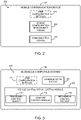
FIG. 2 is a simplified block diagram of at least one embodiment of an environment of a mobile communication device of the system ofFIG. 1 ; -
FIG. 3 is a simplified block diagram of at least one embodiment of an environment of an in-vehicle computing system of the system ofFIG. 1 ; -
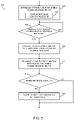
FIG. 4 is a simplified flow diagram of at least one embodiment of a method for retrieving vehicle configuration settings from an in-vehicle computing system, which may be executed by the mobile communication device ofFIG. 2 ; -
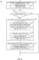
FIG. 5 is a simplified flow diagram of at least one embodiment of a method for communicating vehicle configuration settings to a mobile communication device, which may be executed by the in-vehicle system ofFIG. 3 ; -
FIG. 6 is a simplified flow diagram of at least one embodiment of a method for configure vehicle configuration settings of the in-vehicle computing system, which may be executed by the mobile communication device ofFIG. 2 ; -
FIG. 7 is a simplified flow diagram of at least one embodiment of a method for adjusting vehicle controls based on user vehicle configuration settings, which may be executed by the in-vehicle system ofFIG. 3 ; and -
FIG. 8 is a simplified illustration of at least one embodiment of a graphical user interface that may be displayed on the mobile communication device ofFIG. 2 during operation. - While the concepts of the present disclosure are susceptible to various modifications and alternative forms, specific exemplary embodiments thereof have been shown by way of example in the drawings and will herein be described in detail. It should be understood, however, that there is no intent to limit the concepts of the present disclosure to the particular forms disclosed, but on the contrary, the intention is to cover all modifications, equivalents, and alternatives consistent with the present disclosure and the appended claims.
- In the following description, numerous specific details such as logic implementations, opcodes, means to specify operands, resource partitioning/sharing/duplication implementations, types and interrelationships of system components, and logic partitioning/integration choices are set forth in order to provide a more thorough understanding of the present disclosure. It will be appreciated, however, by one skilled in the art that embodiments of the disclosure may be practiced without such specific details. In other instances, control structures, gate level circuits and full software instruction sequences have not been shown in detail in order not to obscure the invention. Those of ordinary skill in the art, with the included descriptions, will be able to implement appropriate functionality without undue experimentation.
- References in the specification to "one embodiment," "an embodiment," "an example embodiment," etc., indicate that the embodiment described may include a particular feature, structure, or characteristic, but every embodiment may not necessarily include the particular feature, structure, or characteristic. Moreover, such phrases are not necessarily referring to the same embodiment. Further, when a particular feature, structure, or characteristic is described in connection with an embodiment, it is submitted that it is within the knowledge of one skilled in the art to effect such feature, structure, or characteristic in connection with other embodiments whether or not explicitly described.
- Embodiments of the invention may be implemented in hardware, firmware, software, or any combination thereof. Embodiments of the invention implemented in a computer system may include one or more bus-based interconnects between components and/or one or more point-to-point interconnects between components. Embodiments of the invention may also be implemented as instructions carried by or stored on a transitory or non-transitory machine-readable (e.g., computer-readable) medium, which may be read and executed by one or more processors. A machine-readable medium may be embodied as any device, mechanism, or physical structure for storing or transmitting information in a form readable by a machine (e.g., a computing device). For example, a machine-readable medium may be embodied as read only memory (ROM); random access memory (RAM); magnetic disk storage media; optical storage media; flash memory devices; mini- or micro-SD cards, memory sticks, electrical signals, and others.
- In the drawings, specific arrangements or orderings of schematic elements, such as those representing devices, modules, instruction blocks and data elements, may be shown for ease of description. However, it should be understood by those skilled in the art that the specific ordering or arrangement of the schematic elements in the drawings is not meant to imply that a particular order or sequence of processing, or separation of processes, is required. Further, the inclusion of a schematic element in a drawing is not meant to imply that such element is required in all embodiments or that the features represented by such element may not be included in or combined with other elements in some embodiments.
- In general, schematic elements used to represent instruction blocks may be implemented using any suitable form of machine-readable instruction, such as software or firmware applications, programs, functions, modules, routines, processes, procedures, plug-ins, applets, widgets, code fragments and/or others, and that each such instruction may be implemented using any suitable programming language, library, application programming interface (API), and/or other software development tools. For example, some embodiments may be implemented using Java, C++, and/or other programming languages. Similarly, schematic elements used to represent data or information may be implemented using any suitable electronic arrangement or structure, such as a register, data store, table, record, array, index, hash, map, tree, list, graph, file (of any file type), folder, directory, database, and/or others.
- Further, in the drawings, where connecting elements, such as solid or dashed lines or arrows, are used to illustrate a connection, relationship or association between or among two or more other schematic elements, the absence of any such connecting elements is not meant to imply that no connection, relationship or association can exist. In other words, some connections, relationships or associations between elements may not be shown in the drawings so as not to obscure the disclosure. In addition, for ease of illustration, a single connecting element may be used to represent multiple connections, relationships or associations between elements. For example, where a connecting element represents a communication of signals, data or instructions, it should be understood by those skilled in the art that such element may represent one or multiple signal paths (e.g., a bus), as may be needed, to effect the communication.
- Referring now to
FIG. 1 , in one embodiment, asystem 100 for the portable configuration of vehicle occupant controls of avehicle 110 includes amobile communication device 102 and an in-vehicle computing system 104, which is located in thevehicle 110. As discussed in more detail below, themobile communication device 102 maintains user vehicle configuration settings for vehicle occupant controls (e.g., ergonomic, comfort, and/or mechanical controls) of thevehicle 110 and communicates such user vehicle configuration settings to the in-vehicle computing system 104. In response, the in-vehicle computing system 104 implements the user vehicle configuration settings to adjust the vehicle occupant controls. In this way, a user of themobile communication device 102 may quickly and automatically adjust the vehicle occupant controls to his/her liking without the need of manually adjusting each control. Additionally, because themobile communication device 102 stores the user configuration settings, the user need not remember the amount or level of adjustment the user has determined, through experience or knowledge, to be optimal for him/her. Further, as themobile communication device 102 can store multiple user vehicle configuration settings, themobile communication device 102 may be used to interface with in-vehicle computing systems of different vehicles to adjust vehicle occupant controls based user settings from the same or different users of themobile communication device 102. - The
mobile communication device 102 may be embodied as any type of mobile communication device capable of communicating with the in-vehicle computing system 104 and performing the functions described herein. For example, themobile communication device 102 may be embodied as, but not limited to, a smart phone, a tablet computer, a notebook computer, a mobile internet device, a mobile computing device, a personal digital assistant, a cellular phone, a messaging device, a laptop computer, a portable data storage device having communication capabilities, and/or other portable computing devices capable of communicating with the in-vehicle computing system 104. Of course, it should be appreciated that thesystem 100 may include additionalmobile communication devices 102 in some embodiments. For example, each occupant of thevehicle 110 may have a mobile communication device having similar features as those described below with regard to themobile communication device 102 and configured to perform similar functions. - In the illustrative embodiment of
FIG. 1 , themobile communication device 102 includes aprocessor 120, an I/O subsystem 124, amemory 126, adata storage 128, acommunication circuitry 130, and one or moreperipheral devices 132. In some embodiments, several of the foregoing components may be incorporated on a motherboard or main board of themobile communication device 102, while other components may be communicatively coupled to the motherboard via, for example, a peripheral port. Furthermore, it should be appreciated that themobile communication device 102 may include other components, sub-components, and devices commonly found in a computer and/or computing device, which are not illustrated inFIG. 1 for clarity of the description. - The
processor 120 of themobile communication device 102 may be embodied as any type of processor capable of executing software/firmware, such as a microprocessor, digital signal processor, microcontroller, or the like. Theprocessor 120 is illustratively embodied as a single core processor having aprocessor core 122. However, in other embodiments, theprocessor 120 may be embodied as a multi-core processor havingmultiple processor cores 122. Additionally, themobile communication device 102 may includeadditional processors 120 having one ormore processor cores 122. - The I/
O subsystem 124 of themobile communication device 102 may be embodied as circuitry and/or components to facilitate input/output operations with theprocessor 120 and/or other components of themobile communication device 102. In some embodiments, the I/O subsystem 124 may be embodied as a memory controller hub (MCH or "northbridge"), an input/output controller hub (ICH or "southbridge"), and a firmware device. In other embodiments, the I/O subsystem 124 may be embodied as a platform controller hub (PCH). In such embodiments, the memory controller hub (MCH) may be incorporated in or otherwise associated with theprocessor 120, and theprocessor 120 may communicate directly with the memory 126 (as shown by the hashed line inFIG. 1 ). Additionally, in other embodiments, the I/O subsystem 124 may form a portion of a system-on-a-chip (SoC) and be incorporated, along with theprocessor 120 and other components of themobile communication device 102, on a single integrated circuit chip. - The
processor 120 is communicatively coupled to the I/O subsystem 124 via a number of signal paths. Those signal paths (and other signal paths illustrated inFIG. 1 ) may be embodied as any type of signal paths capable of facilitating communication between the various components of themobile communication device 102. For example, the signal paths may be embodied as any number of point-to-point links, wires, cables, light guides, printed circuit board traces, vias, bus, intervening devices, and/or the like. - The
memory 126 of themobile communication device 102 may be embodied as, or otherwise include, one or more memory devices or data storage locations including, for example, dynamic random access memory devices (DRAM), synchronous dynamic random access memory devices (SDRAM), double-data rate synchronous dynamic random access memory device (DDR SDRAM), mask read-only memory (ROM) devices, erasable programmable ROM (EPROM), electrically erasable programmable ROM (EEPROM) devices, flash memory devices, and/or other volatile and/or non-volatile memory devices. Thememory 126 is communicatively coupled to the I/O subsystem 124 via a number of signal paths. Although only asingle memory device 126 is illustrated inFIG. 1 , themobile communication device 102 may include additional memory devices in other embodiments. Various data and software may be stored in thememory 126. For example, one or more operating systems, applications, programs, libraries, and drivers that make up the software stack executed by theprocessor 120 may reside inmemory 126 during execution. - The
data storage 128 may be embodied as any type of device or devices configured for the short-term or long-term storage of data such as, for example, memory devices and circuits, memory cards, hard disk drives, solid-state drives, or other data storage devices. In the illustrative embodiment, themobile communication device 102 maintains one or more uservehicle configuration settings 170 in thedata storage 128. As discussed in more detail below, the uservehicle configuration settings 170 is embodied as data usable by the in-vehicle computing system 104 to adjust various vehicle occupant controls. The particular make-up and format of the uservehicle configuration settings 170 may vary depending on, for example, the type ofvehicle 110, the type of in-vehicle computing system 104, the type and number of vehicle occupant controls of thevehicle 110, and/or other features or factors related to thevehicle 110. Additionally, it should be appreciated that themobile communication device 102 may store a plurality ofuser configuration settings 170 indata storage 128, such as user vehicle configuration settings for different users and/or different vehicles. - The
communication circuitry 130 of themobile communication device 102 may include any number of devices and circuitry for enabling communications between themobile communication device 102 and the in-vehicle computing system 104 as discussed in more detail below. Thecommunication circuitry 130 may be configured to use any one or more communication technology and associated protocols to communicate with the in-vehicle computing system 104. For example, in one particular embodiment, thecommunication circuitry 130 is embodied as a wireless communication circuitry configured to communicate with the in-vehicle computing system 104 using a wireless communication protocol such as Bluetooth®, Wi-Fi®, WiMAX, and/or other wireless communication circuitry. - In some embodiments, the
mobile communication device 102 may also include one or moreperipheral devices 132. Suchperipheral devices 132 may include any number of additional input/output devices, interface devices, and/or other peripheral devices. For example, theperipheral devices 132 may include a display, a graphics circuitry, a keypad or keyboard, a speaker, and/or other input/output devices, interface devices, and/or peripheral devices. - The in-
vehicle computing system 104 may be embodied as any type of vehicle computing system capable of performing the functions described herein. For example, the in-vehicle computing system 104 may be embodied as, or otherwise include, an in-vehicle occupant controls system, an in-vehicle infotainment system, and/or other in-vehicle computing system or sub-system. In the illustrative embodiment ofFIG. 1 , the in-vehicle computing system includes aprocessor 140, an I/O subsystem 144, amemory 146, adata storage 148,communication circuitry 150, and one or moreperipheral devices 152. Of course, it should be appreciated that the in-vehicle computing system 104 may include other components, sub-components, and devices commonly found in in-vehicle computing system 104 and similar computing systems, which are not illustrated inFIG. 1 for clarity of the description. - The
processor 140 of the in-vehicle computing system 104 may be embodied as any type of processor or processing circuitry capable of executing software/firmware, such as a microprocessor, digital signal processor, microcontroller, or the like. Theprocessor 140 is illustratively embodied as a single core processor having aprocessor core 142. However, in other embodiments, theprocessor 140 may be embodied as a multi-core processor havingmultiple processor cores 142. Additionally, the in-vehicle computing system 104 may includeadditional processors 140 having one ormore processor cores 142. - The I/
O subsystem 144 of the in-vehicle computing system 104 may be embodied as circuitry and/or components to facilitate input/output operations with theprocessor 140 and/or other components of the in-vehicle computing system 104. In some embodiments, the I/O subsystem 144 may be embodied as a memory controller hub (MCH or "northbridge"), an input/output controller hub (ICH or "southbridge"), and a firmware device. In other embodiments, the I/O subsystem 144 may be embodied as a platform controller hub (PCH). In such embodiments, the memory controller hub (MCH) may be incorporated in or otherwise associated with theprocessor 140, and theprocessor 140 may communicate directly with the memory 146 (as shown by the hashed line inFIG. 1 ). Additionally, in other embodiments, the I/O subsystem 144 may form a portion of a system-on-a-chip (SoC) and be incorporated, along with theprocessor 140 and other components of the in-vehicle computing system 104, on a single integrated circuit chip. - The
processor 140 is communicatively coupled to the I/O subsystem 144 via a number of signal paths. Those signal paths (and other signal paths illustrated inFIG. 1 ) may be embodied as any type of signal paths capable of facilitating communication between the various components of the in-vehicle computing system 104. For example, the signal paths may be embodied as any number of point-to-point links, wires, cables, light guides, printed circuit board traces, vias, bus, intervening devices, and/or the like. - The
memory 146 of the in-vehicle computing system 104 may be embodied as, or otherwise include, one or more memory devices or data storage locations including, for example, dynamic random access memory devices (DRAM), synchronous dynamic random access memory devices (SDRAM), double-data rate synchronous dynamic random access memory device (DDR SDRAM), mask read-only memory (ROM) devices, erasable programmable ROM (EPROM), electrically erasable programmable ROM (EEPROM) devices, flash memory devices, and/or other volatile and/or non-volatile memory devices. Thememory 146 is communicatively coupled to the I/O subsystem 144 via a number of signal paths. Although only asingle memory device 146 is illustrated inFIG. 1 , the in-vehicle computing system 104 may include additional memory devices in other embodiments. Various data and software may be stored in thememory 146. For example, one or more operating systems, applications, programs, libraries, and drivers that make up the software stack executed by theprocessor 140 may reside inmemory 146 during execution. - The
data storage 148 may be embodied as any type of device or devices configured for the short-term or long-term storage of data such as, for example, memory devices and circuits, memory cards, hard disk drives, solid-state drives, or other data storage devices. In the illustrative embodiment, the in-vehicle computing system 104 may store uservehicle configuration settings 170 in thedata storage 148. - The
communication circuitry 150 of the in-vehicle computing system 104 may include any number of devices and circuitry for enabling communications between the in-vehicle computing system 104 and themobile communication device 102. As discussed above with regard to thecommunication circuitry 130, thecommunication circuitry 150 may be configured to use any one or more communication technology and associated protocols to communicate with themobile communication device 102. As such, in one particular embodiment, thecommunication circuitry 150 is embodied as a wireless communication circuitry configured to communicate with the in-vehicle computing system 104 using a wireless communication protocol such as Bluetooth®, Wi-Fi®, WiMAX, and/or other wireless communication circuitry. - The in-
vehicle computing system 104 may also include one or moreperipheral devices 132. Suchperipheral devices 132 may include any number of additional input/output devices, interface devices, and/or other peripheral devices. For example, theperipheral devices 132 may include a display, a graphics circuitry, a keypad or keyboard, a speaker, and/or other input/output devices, interface devices, and/or peripheral devices. - In some embodiments, the in-
vehicle computing system 104 may also include one or moreergonomic control circuitry 160,comfort control circuitry 162, and/ormechanical control circuitry 164. Each of thecircuitries ergonomic control circuitry 160 may control any one or more ergonomic control of thevehicle 110. Such ergonomic controls may include, but are not limited to, the viewing angle controls of the side mirrors, steering wheel tilt controls, vehicle seat positioning controls, pedal positioning controls, shifter positioning controls, and/or controls for adjusting any other ergonomic feature of thevehicle 110 that may modify and/or improve the human-interfacing of thevehicle 110. Thecomfort control circuitry 162 may control any one or more comfort control of thevehicle 110. Such comfort controls may include, but are not limited to, temperature controls, radio controls, window controls, volume controls, backup indicator controls, internal lighting controls, and/or controls for adjusting any other comfort feature of thevehicle 110 that may modify and/or improve the comfort of a vehicle occupant. Themechanical control circuitry 164 may control any one or more mechanical control of thevehicle 110. Such mechanical controls may include, but are not limited to, engine power mapping controls, vehicle performance mode controls, acceleration curve controls, and/or controls for adjusting any other mechanical feature of thevehicle 110 vehicle that may modify and/or improve the performance or operational state of thevehicle 110. - Referring now to
FIG. 2 , in one embodiment, themobile communication device 102 may establish anenvironment 200 during operation. Theillustrative environment 200 includes a vehicleconfiguration management module 202 and acommunication module 204, each of which may be embodied as software, firmware, hardware, or a combination thereof. As discussed in more detail below, the vehicleconfiguration management module 202 is configured to maintain the uservehicle configuration settings 170 and communicate with the in-vehicle computing system 104, via thecommunication module 204, to transfer the uservehicle configuration settings 170, or an identifier of such settings, thereto. Additionally, the vehicleconfiguration management module 202 may communicate with the in-vehicle computing system 104, via thecommunication module 204, to receive new or current vehicle configuration settings of thevehicle 110 and store such current settings in thedata storage 128. Further, in embodiments in which multiple uservehicle configuration settings 170 are stored on themobile communication device 102, the vehicleconfiguration management module 202 may provide for user selection of one or more of the plurality of stored uservehicle configuration settings 170. - Referring now to
FIG. 3 , in one embodiment, the in-vehicle computing system 104 may establish anenvironment 300 during operation. Theillustrative environment 300 includes a vehicleconfiguration management module 202 and acommunication module 304, each of which may be embodied as software, firmware, hardware, or a combination thereof. The vehicleconfiguration management module 202 is configured to monitor, manage, and control various vehicle occupant controls of the vehicle. For example, in the illustrative embodiment, the vehicleconfiguration control module 302 may include anergonomic control module 310 to control theergonomic control circuitry 160, acomfort control module 312 to control thecomfort control circuitry 162, and/or amechanical control module 314 to control themechanical control circuitry 164. As discussed in more detail below, the vehicleconfiguration control module 302 may communicate, via thecommunication module 304, with themobile communication device 102 to receive and/or transfer vehicle configuration settings. - Referring now to
FIG. 4 , in use, themobile communication device 102 may execute amethod 400 for retrieving vehicle configuration settings from the in-vehicle computing system 104. Themethod 400 begins withblock 402 in which themobile communication device 102 establishes a connection with the in-vehicle computing system 104. As discussed above, thecommunication circuitries mobile communication device 102 may perform a pairing process inblock 404 to pair with the in-vehicle computing system 104 to establish a communication link therebetween. - In
block 406, themobile communication device 102 receives the current vehicle configuration settings from the in-vehicle computing system 104. As discussed above, the vehicle configuration settings may be embodied as any type of data usable by the in-vehicle computing system 104 to adjust various vehicle occupant controls. In some embodiments, the user of themobile communication device 102 may initially manually adjust one or more vehicle occupant controls inblock 408 to the user's liking. For example, the user may adjust the seat positioning, the temperature control, and the performance mode of thevehicle 110. After the user has adjusted the vehicle occupant controls to his/her liking, the user may operate themobile communication device 102 to request the current vehicle configuration settings from the in-vehicle computing system 104 inblock 410. Subsequently, inblock 412, themobile communication device 102 receives the current vehicle configuration settings from the in-vehicle computing system 104. In some embodiments, themobile communication device 102 may receive only recently modified or updated vehicle configuration settings (e.g., only settings for those vehicle occupant controls adjusted within a pre-defined time period). Alternatively, themobile communication device 102 may receive a complete set of current vehicle configuration settings inblock 406. - In
block 406, themobile communication device 102 stores the current vehicle configuration settings as uservehicle configuration settings 170 in thedata storage 128. In some embodiments, the uservehicle configuration settings 170 may be stored in association with other data inblock 416. For example, the uservehicle configuration settings 170 may be stored in association with a vehicle identifier that identifies the vehicle 110 (e.g., uniquely identifies thevehicle 110 from other vehicles for which user vehicle configuration settings have been stored in the data storage 128). Additionally or alternatively, the uservehicle configuration settings 170 may be stored in association with a user identifier that identifies the current user of themobile communication device 102. Further, in some embodiments, the uservehicle configuration settings 170 may be stored in association with a priority identifier that identifies a priority of the uservehicle configuration settings 170 relative to other user vehicle configuration settings 170 (which may be stored on themobile communication device 102 or another mobile communication device). As discussed in more detail below, the priority identifier may be used by the in-vehicle computing system 104 to resolve conflicts between user vehicle configuration settings (e.g., when two users transmit two conflicting uservehicle configuration settings 170 to the in-vehicle computing system 104). - Referring now to
FIG. 5 , in use, the in-vehicle computing system 104 may execute amethod 500 for collecting and communicating vehicle configuration settings to themobile communication device 102. Themethod 500 begins withblock 502 in which the in-vehicle computing system 104 establishes a connection with themobile communication device 102. As discussed above, thecommunication circuitries vehicle computing system 104 may perform a pairing process to block 504 to pair with themobile communication device 102 to establish a communication link therebetween. - In
block 506, the in-vehicle computing system 104 determines whether a request for the current vehicle configuration settings of thevehicle 110 has been received from themobile communication device 102. If so, themethod 500 advances to block 508 in which the in-vehicle computing system 104 collects the current vehicle configuration settings. To do so, the vehicleconfiguration control module 302 may communicate with the various vehicle occupant controls, via thecorresponding control module configuration control module 302 may communicate with a seat positioning control module to determine data indicative of the current seat position or adjustment inblock 508. It should be appreciated that the in-vehicle computing system 104 may query, or otherwise communicate, with every, some, or just one vehicle occupant control to determine one or more vehicle configuration settings inblock 508. - In
block 510, the in-vehicle computing system 104 transmits the current vehicle configuration settings to themobile communication device 102. Additionally, in some embodiments, the in-vehicle computing system 104 may determine whether local storage of the current vehicle configuration settings is required inblock 512. If so, the in-vehicle computing system 104 stores the current vehicle configuration settings in thelocal data storage 148 inblock 514. The in-vehicle computing system 104 may store such vehicle configuration settings in association with a user identifier and/or a priority identifier as discussed above with regard to themobile communication device 102. In embodiments in which the vehicle configuration settings are stored in thedata storage 148, the in-vehicle computing system 104 may transmit a vehicle configuration settings identifier to themobile communication device 102 inblock 510, rather than the complete current vehicle configuration settings. In such embodiments, the vehicle configuration settings identifier uniquely identifies the current vehicle configuration settings from other vehicle configuration settings stored in thedata storage 148. Additionally, in such embodiments, themobile communication device 102 need only transmit the vehicle configuration settings identifier to the in-vehicle computing system 104, rather than the complete user vehicle configuration settings, which is used by the in-vehicle computing system 104 to fetch the corresponding user vehicle configuration settings from thedata storage 148 as discussed in more detail below. - Referring now to
FIG. 6 , in use, themobile communication device 102 may also execute amethod 600 for configuring vehicle configuration settings of the in-vehicle computing system 104. Themethod 600 begins withblock 602 in which themobile communication device 102 establishes a connection with the in-vehicle computing system 104. As discussed above with regard to block 404 of themethod 400, themobile communication device 102 may perform a pairing process inblock 404 to pair with the in-vehicle computing system 104 to establish a communication link therebetween. - In
block 606, themobile communication device 102 determines whether to configure the vehicle configuration settings of thevehicle 110. In some embodiments, the configuration of the vehicle settings may occur automatically or semi-automatically with little or no intervention by the user of themobile communication device 102. For example, themobile communication device 102 may automatically attempt to configure the vehicle configuration settings in response to the establishment of a communication connection with the in-vehicle computing system 104 in block 602 (i.e., in response to themobile communication device 102 being brought into proximity with the in-vehicle computing system 104). Additionally or alternatively, themobile communication device 102 may configure the vehicle configuration settings in response to receiving a configuration authorization signal from the in-vehicle computing system 104. As discussed in more detail below in regard toFIG. 7 , such configuration authorization signal may be generated in response to activation of a component of thevehicle 110 such as the door handle, brake, ignition, or the like. In yet other embodiments, the user may manually opt to configure the vehicle configuration settings by selecting an appropriate command from a user interface of themobile communication device 102. - If the
mobile computing device 102 determines that the vehicle configuration settings are to be configured, themethod 600 advances to block 608 in which the set of uservehicle configuration settings 170 to transfer to the in-vehicle computing system 104 is determined. As discussed above, themobile communication device 102 may store multiple sets of uservehicle configuration settings 170 in some embodiments. In such embodiments, the user of themobile communication device 102 may display a graphical user interface on a display of thedevice 102 to allow the user to select the desired set of user vehicle configuration settings. For example, as shown inFIG. 8 , themobile communication device 102 may display aseating chart interface 800 that allows a user of themobile communication device 102 to select his/her seating position within thevehicle 110. Themobile communication device 102 may have stored therein different user vehicle configuration settings for one or more different seating positions. For example, the user may select different seat positions for when he/she is the driver or a passenger in thevehicle 110. - Referring back to
FIG. 6 , themobile communication device 102 receives the user's selection inblock 614 and retrieves the selected user vehicle configuration settings inblock 616. As discussed above, in some embodiments, the uservehicle configuration settings 170 may be embodied as a user vehicle configuration settings identifier, which may be retrieved inblock 616, rather than a complete set of user vehicle configuration settings. - In some embodiments, the
mobile communication device 102 may be configured to select automatically or semi-automatically the uservehicle configuration settings 170 from multiple user vehicle configuration settings stored on themobile communication device 102. In such embodiments, themobile communication device 102 may determine a vehicle identifier, which identifies thevehicle 110, inblock 610. For example, themobile communication device 102 may receive the vehicle identifier from the in-vehicle computing system 104 during the pairing process ofblock 604. Subseuqently, inblock 612, themobile communication device 102 retrieves the user vehicle configuration settings form thedata storage 128 corresponding to the vehicle identifier. - After the user vehicle configuration settings have been determined and retrieved in
block 608, themobile communication device 102 transmits the retrieved user vehicle configuration settings in block 518. As discussed above, rather than transmitting the complete user vehicle configuration settings, themobile communication device 102 may transmit a user vehicle configuration settings identifier that identifies the selected or determined user vehicle configuration settings inblock 620. - Referring now to
FIG. 7 , in use, the in-vehicle computing system 104 may execute amethod 700 for adjusting one or more vehicle occupant controls based on user vehicle configuration settings. Themethod 700 begins withblock 702 in which the in-vehicle computing system 104 establishes a connection with themobile communication device 102. As discussed above with regard to block 504 of themethod 500, the in-vehicle computing system 104 may perform a pairing process inblock 704 to pair with themobile communication device 102 to establish a communication link therebetween. - In
block 706, the in-vehicle computing system 104 determines whether to allow modification of the vehicle configuration settings. As discussed above, the vehicle configuration settings may be configured automatically or semi-automatically in some embodiments. For example, the in-vehicle computing system 104 may provide a period of time during which vehicle configuration settings may be automatically adjusted by themobile communication device 102 in response to the establishment of the communication connection in block 702 (i.e., in response to themobile communication device 102 being brought into proximity of the in-vehicle computing system 104). Additionally or alternatively, the in-vehicle computing system 104 may transmit a configuration authorization signal to themobile communication device 102 to indicate that themobile communication device 102 may modify the vehicle configuration settings if desired. In some embodiments, the configuration authorization signal may be generated in response to activation of a component of thevehicle 110 such as the lifting of a door handle, the depression of the break, selection of a particular button, activation of the ignition and/or other component of thevehicle 110. Yet further, in some embodiments, thevehicle computing system 104 may receive a request from themobile communication device 102 to modify the vehicle configuration settings inblock 706. - If the in-
vehicle computing system 102 determines that the vehicle configuration settings are to be modified, themethod 500 advances to block 708 in which the in-vehicle computing system 104 receives the uservehicle configuration settings 170 form themobile communication device 102. As discussed above, rather than transmitting the complete uservehicle configuration settings 170, themobile communication device 102 may transfer only a user vehicle configuration settings identifier that identifies the desired user vehicle configuration settings 170 (which are stored on thedata storage 148 of the in-vehicle computing system 104). In such embodiments, the in-vehicle computing system 104 receives the user vehicle configuration settings identifier from themobile communication device 102 in block 710 and retrieves the corresponding user vehicle configuration settings from thedata storage 148 based on the user vehicle configuration settings identifier inblock 712. - In
block 714, the in-vehicle computing system 104 resolves any priority conflicts between different user vehicle configuration settings that may occur in response to the recent receive/retrieved uservehicle configuration settings 170. As discussed above, the in-vehicle computing system 104 may be configured to resolve such priority conflicts based on a priority identifier associated with each set of user vehicle configuration settings. That is, the uservehicle configuration settings 170, or components thereof, having the highest (or lowest) priority identifier may be used in place of other user vehicle configuration settings. In this way, one user's preference (e.g., a parent's preference) for vehicle configuration settings may override another user's preference (e.g., a child's preference). - In
block 716, the in-vehicle computing system 104 adjusts one or more vehicle occupant controls based on, or as a function of, the uservehicle configuration settings 170 received/retrieved inblock 708. For example, the in-vehicle computing system 104 may adjust ergonomic controls inblock 718, comfort controls inblock 720, and/or mechanical controls inblock 722. In this way, a user of themobile communication device 102 may remotely and automatically adjust the vehicle occupant controls to desired settings without manually adjusting each control.
Claims (11)
- A mobile communication device (102) for remotely configuring vehicle configuration settings of a vehicle, the mobile communication device comprising:a data storage (128) arranged to store therein a user vehicle configuration settings (170), the user vehicle configuration settings comprising data usable by an in-vehicle computing system (104) to configure vehicle occupant controls of the vehicle; anda vehicle configuration management module (202) arranged to retrieve the user vehicle configuration settings from the data storage and transmit the retrieved user vehicle configuration settings to the in-vehicle computing system to configure the vehicle occupant controls, wherein the vehicle configuration management module is further arranged to:request vehicle configuration settings from the in-vehicle computing system, the vehicle configuration settings identifying current settings of vehicle occupant controls managed by the in-vehicle computing system of the vehicle;receive the vehicle configuration settings from the in-vehicle computing system using a communication module (204); andstore the vehicle configuration settings in the data storage (128),wherein the vehicle configuration management module is arranged to:display a selection of a plurality of selectable user vehicle configuration settings stored in the data storage on the display;receive a selection of one of the displayed user vehicle configuration settings;determine a user configuration settings identifier for the selected user vehicle configuration settings; andtransmit the user configuration settings identifier to the in-vehicle computing system of the vehicle.
- The mobile communication device of claim 1, wherein the vehicle configuration management module is to automatically retrieve and transmit the user vehicle configuration settings in response to (i) establishment of a communication connection with the in-vehicle computing system or (ii) receiving a configuration authorization signal from the in-vehicle computing system indicative that a component of the vehicle has been activated.
- The mobile communication device of claim 1, further comprising a display, wherein the vehicle configuration management module to:display a selection of a plurality of selectable user vehicle configuration settings stored in the data storage on the display;receive a selection of one of the displayed user vehicle configuration settings corresponding to a seat location of the vehicle; andretrieve the selected user configuration settings from the data storage.
- An in-vehicle computing system (104) of a vehicle (110) for managing vehicle configuration settings; the in-vehicle computing system comprising:a communication module (304) arranged to receive user vehicle configuration settings (170) from a mobile communication device (102), the user vehicle configuration settings comprising data usable by the in-vehicle computing system to configure one or more vehicle occupant controls of the vehicle that are managed by the in-vehicle system; anda vehicle configuration control module (302) arranged to adjust at least one vehicle occupant control of the vehicle as a function of the user vehicle configuration settings, wherein:the communication module is further arranged to receive a request for vehicle configuration settings from the mobile communication device; andthe in-vehicle computing system is arranged to determine current vehicle configuration settings of the vehicle in response to the request and transmit, using the communication module, the current vehicle configuration settings to the mobile communication device,wherein receiving the user vehicle configuration settings comprises receiving a user vehicle configuration setting identifier from the mobile communication device,wherein the in-vehicle computing system further comprises a data storage (148) to store vehicle configuration settings,wherein the user vehicle configuration settings comprise a user vehicle configuration settings identifier, andwherein the in-vehicle computing system is arranged to retrieve a vehicle configuration settings from the data storage corresponding to the user vehicle configuration settings identifier and adjust the at least one vehicle occupant control as a function of the retrieved vehicle configuration settings.
- The in-vehicle computing system of claim 4, wherein the vehicle configuration control module is to generate a vehicle authorization signal in response to activation of a component of the vehicle and the communication module is to transmit the vehicle authorization signal to the mobile communication device to inform the mobile communication device that the vehicle configuration settings may be adjusted.
- The in-vehicle computing system of claim 4, wherein:the communication module to receive an additional user vehicle configuration settings from an additional mobile communication device; andthe vehicle configuration control module to resolve a priority conflict between the user vehicle configuration settings and the additional user vehicle configuration settings to determine a final user vehicle configuration settings and adjust at least one vehicle occupant control as a function of the final vehicle configuration settings, wherein the vehicle configuration control module is to resolve the priority conflict as a function of a priority identifier received with each user vehicle configuration settings.
- A method for remotely configuring vehicle configuration settings using a mobile communication device (102), the method being performed by the mobile communication device, the method comprising:retrieving (616) user vehicle configuration settings from a data storage (128) of the mobile communication device, the user vehicle configuration settings to configure vehicle occupant controls managed by an in-vehicle computing system of the vehicle;transmitting (618) the user vehicle configuration settings to the in-vehicle computing system to configure the vehicle occupant controls;requesting (410) vehicle configuration settings from the in-vehicle computing system, the vehicle configuration settings identifying current settings of vehicle occupant controls managed by the in-vehicle computing system of the vehicle;receiving, (412) on the mobile communication device, the vehicle configuration settings from the in-vehicle computing system; andstoring (414) the vehicle configuration settings on the mobile communication device in association with a vehicle identifier that identifies the vehicle and in association with a priority identifier that identifies the priority of the vehicle configuration settings relative to other vehicle configuration settings,wherein retrieving the user vehicle configuration settings comprises:receiving a selection of a user vehicle configuration settings from a plurality of selectable user vehicle configuration settings stored in the data storage (128) of the mobile communication device; anddetermining a user configuration settings identifier for the selected user vehicle configuration settings;wherein transmitting the user vehicle configuration settings comprises transmitting the user configuration settings identifier to the in-vehicle computing system of the vehicle.
- The method of claim 7, further comprising:displaying the user configuration settings on a display of the mobile communication device; andreceiving, on the mobile communication device, a selection of a user configuration setting of the user configuration settings; andwherein transmitting the user vehicle configuration settings comprises transmitting the selected user configuration setting to the in-vehicle computing system of the vehicle.
- A method for managing vehicle configuration settings of a vehicle, the method comprising:receiving, with an in-vehicle computing system (104) of the vehicle, user vehicle configuration settings from a mobile communication device (102), the user vehicle configuration settings comprising data usable by the in-vehicle computing system to configure one or more vehicle occupant controls managed by the in-vehicle system;adjusting, using the in-vehicle computing system, at least one vehicle occupant control of the vehicle as a function of the user vehicle configuration settings;receiving, with the in-vehicle computing system, a request (506) for vehicle configuration settings from the mobile communication device;determining (508), with the in-vehicle computing system, current vehicle configuration settings of the vehicle in response to the request; andtransmitting the current vehicle configuration settings to the mobile communication device,wherein receiving the user vehicle configuration settings comprises:receiving a user vehicle configuration settings identifier from the mobile communication device; andretrieving a vehicle configuration settings from a data storage (148) of the in-vehicle computing system corresponding to the user vehicle configuration settings identifier,wherein the user vehicle configuration settings comprise the user vehicle configuration settings identifier,wherein adjusting the at least one vehicle occupant control comprises adjusting the at least one vehicle occupant control as a function of the retrieved vehicle configuration settings.
- The method of claim 9, further comprising transmitting a vehicle authorization signal to the mobile communication device in response to activation of a component of the vehicle, the vehicle authorization signal informing the mobile communication device that the vehicle configuration settings may be adjusted.
- One or more machine readable media comprising a plurality of instructions stored thereon that, in response to execution, cause a computing device to perform the method of any of claims 7-10.
Applications Claiming Priority (3)
| Application Number | Priority Date | Filing Date | Title |
|---|---|---|---|
| US13/629,119 US9426274B2 (en) | 2012-09-27 | 2012-09-27 | Device, method, and system for portable configuration of vehicle controls |
| PCT/US2013/062010 WO2014052651A1 (en) | 2012-09-27 | 2013-09-26 | Device, method, and system for portable configuration of vehicle controls |
| EP13841692.0A EP2901805A4 (en) | 2012-09-27 | 2013-09-26 | Device, method, and system for portable configuration of vehicle controls |
Related Parent Applications (1)
| Application Number | Title | Priority Date | Filing Date |
|---|---|---|---|
| EP13841692.0A Division EP2901805A4 (en) | 2012-09-27 | 2013-09-26 | Device, method, and system for portable configuration of vehicle controls |
Publications (2)
| Publication Number | Publication Date |
|---|---|
| EP3509388A1 EP3509388A1 (en) | 2019-07-10 |
| EP3509388B1 true EP3509388B1 (en) | 2023-01-25 |
Family
ID=50339658
Family Applications (2)
| Application Number | Title | Priority Date | Filing Date |
|---|---|---|---|
| EP19159218.7A Active EP3509388B1 (en) | 2012-09-27 | 2013-09-26 | Device, method, and system for portable configuration of vehicle controls |
| EP13841692.0A Ceased EP2901805A4 (en) | 2012-09-27 | 2013-09-26 | Device, method, and system for portable configuration of vehicle controls |
Family Applications After (1)
| Application Number | Title | Priority Date | Filing Date |
|---|---|---|---|
| EP13841692.0A Ceased EP2901805A4 (en) | 2012-09-27 | 2013-09-26 | Device, method, and system for portable configuration of vehicle controls |
Country Status (5)
| Country | Link |
|---|---|
| US (1) | US9426274B2 (en) |
| EP (2) | EP3509388B1 (en) |
| CN (1) | CN104584675B (en) |
| BR (1) | BR112015004551A2 (en) |
| WO (1) | WO2014052651A1 (en) |
Families Citing this family (40)
| Publication number | Priority date | Publication date | Assignee | Title |
|---|---|---|---|---|
| US20130197674A1 (en) | 2012-01-30 | 2013-08-01 | Apple Inc. | Automatic configuration of self-configurable environments |
| US9426274B2 (en) | 2012-09-27 | 2016-08-23 | Intel Corporation | Device, method, and system for portable configuration of vehicle controls |
| US20140163771A1 (en) * | 2012-12-10 | 2014-06-12 | Ford Global Technologies, Llc | Occupant interaction with vehicle system using brought-in devices |
| US9224289B2 (en) * | 2012-12-10 | 2015-12-29 | Ford Global Technologies, Llc | System and method of determining occupant location using connected devices |
| WO2014176473A1 (en) * | 2013-04-25 | 2014-10-30 | GM Global Technology Operations LLC | Situation awareness system and method |
| US9910660B2 (en) * | 2013-08-05 | 2018-03-06 | Harman International Industries, Incorporated | Operating system replacement for in-vehicle computing system |
| US20150081175A1 (en) * | 2013-09-18 | 2015-03-19 | Nvidia Corporation | Vehicle user preference system and method of use thereof |
| DE102013223124A1 (en) * | 2013-11-13 | 2015-05-13 | Bayerische Motoren Werke Aktiengesellschaft | Method for transmission and external configuration of personal vehicle function settings |
| US9296338B2 (en) | 2014-02-24 | 2016-03-29 | Intel Corporation | Vehicle mirror adjustment |
| US9509775B2 (en) * | 2014-09-18 | 2016-11-29 | Ford Global Technologies, Llc | Cooperative occupant sensing |
| KR20160137224A (en) * | 2015-05-22 | 2016-11-30 | 삼성전자주식회사 | Apparatus and method for controlling external device |
| US10391958B2 (en) * | 2015-07-30 | 2019-08-27 | Ford Global Technologies, Llc | Methods and systems to customize a vehicle computing system based on an electronic calendar |
| US9640066B2 (en) | 2015-09-21 | 2017-05-02 | Honda Motor Co., Ltd. | System and method for limiting remote control between a portable electronic device and one or more vehicle systems |
| CN106553598A (en) * | 2015-09-29 | 2017-04-05 | 深圳市赛格导航科技股份有限公司 | A kind of method and system of remotely control vehicle |
| WO2017089858A1 (en) * | 2015-11-23 | 2017-06-01 | Bombardier Inc. | System for and method of controlling functions in a vehicle cabin |
| CN105416209B (en) * | 2015-12-07 | 2017-11-10 | 安徽江淮汽车集团股份有限公司 | A kind of onboard system and method for the configuration of automatic pre-set user vehicle personalization |
| CN105599642B (en) * | 2015-12-18 | 2018-02-02 | 小米科技有限责任公司 | Seat Automatic adjustment method, device and terminal |
| CN109415033B (en) * | 2015-12-24 | 2022-03-04 | 北京嘀嘀无限科技发展有限公司 | System and method for vehicle management |
| US10696308B2 (en) * | 2016-06-30 | 2020-06-30 | Intel Corporation | Road condition heads up display |
| CN106364432A (en) * | 2016-08-25 | 2017-02-01 | 乐视控股(北京)有限公司 | Vehicle control method and device as well as vehicle |
| US10652337B2 (en) * | 2016-09-07 | 2020-05-12 | Thundar Power New Energy Vehicle Developmont Company Limited | Passenger side display via a user portable device |
| WO2018149538A1 (en) * | 2017-02-17 | 2018-08-23 | Audi Ag | Method for reducing the probability of encountering a motor vehicle with the same configuration |
| US11433914B2 (en) * | 2017-05-11 | 2022-09-06 | Jyotiranjan Harichandan | System and method for controlling vehicle components using smartphone |
| JP6999706B2 (en) | 2017-07-27 | 2022-01-19 | オッポ広東移動通信有限公司 | Methods and terminals for controlling shared devices |
| CN107380103B (en) * | 2017-07-28 | 2021-09-10 | 延锋安道拓座椅有限公司 | Automatic automobile ornament adjusting method and system based on user identification and cloud sharing |
| US11602991B2 (en) * | 2017-08-07 | 2023-03-14 | Arb Corporation Ltd. | System and method for controlling operation of one or more accessories for a vehicle |
| US10507774B2 (en) * | 2017-08-17 | 2019-12-17 | Accenture Global Solutions Limited | Component configuration based on sensor data |
| JP7039148B2 (en) * | 2017-11-14 | 2022-03-22 | 三菱電機株式会社 | Control systems, equipment, remote controllers, control methods, and programs |
| DE102019217456A1 (en) * | 2018-11-13 | 2020-05-14 | Lear Corporation | METHODS AND SYSTEMS THAT USE THE ORIENTATION OF A TELEPHONE FOR ADJUSTING PHYSICAL OBJECTS AND / OR THE CLOSE TO THE TELEPHONE TO SELECTED PARTS OF PHYSICAL OBJECTS FOR ADJUSTMENT |
| JP7234981B2 (en) * | 2020-03-13 | 2023-03-08 | トヨタ自動車株式会社 | Systems, in-vehicle equipment, and information processing equipment |
| US11518342B2 (en) * | 2021-01-11 | 2022-12-06 | Ford Global Technologies, Llc | Identification of vehicle operators |
| JP7515427B2 (en) * | 2021-02-04 | 2024-07-12 | 日立Astemo株式会社 | Vehicle setting system and method |
| EP4328743A4 (en) * | 2021-04-29 | 2024-10-02 | Human Horizons (Shanghai) Cloud Computing Technology Co., Ltd. | Instruction block processing method, apparatus and device, vehicle, and storage medium |
| CN113220345B (en) * | 2021-04-29 | 2024-03-15 | 华人运通(上海)云计算科技有限公司 | Method, device, equipment and storage medium for processing instruction block |
| JP7723525B2 (en) * | 2021-08-03 | 2025-08-14 | 株式会社Subaru | Vehicle setting system according to occupants, and vehicle |
| JP7632212B2 (en) * | 2021-09-29 | 2025-02-19 | トヨタ自動車株式会社 | Information processing device, vehicle, terminal, information processing method, and information processing program |
| US20240034256A1 (en) * | 2022-07-27 | 2024-02-01 | Paccar Inc | Transfer of driver profile for various vehicles |
| US12337860B2 (en) | 2022-09-19 | 2025-06-24 | Ford Global Technologies, Llc | Vehicle configuration for integration of an accessory |
| US20250222888A1 (en) * | 2024-01-10 | 2025-07-10 | Volvo Car Corporation | Method and apparatus for transmitting signals to adjust functions of a car for a period of use |
| EP4660018A1 (en) * | 2024-06-06 | 2025-12-10 | Harman Becker Automotive Systems GmbH | Method and system for configuring driver preferences in a vehicle |
Family Cites Families (17)
| Publication number | Priority date | Publication date | Assignee | Title |
|---|---|---|---|---|
| US6314401B1 (en) * | 1998-05-29 | 2001-11-06 | New York State Technology Enterprise Corporation | Mobile voice verification system |
| JP4274985B2 (en) * | 2004-03-22 | 2009-06-10 | パナソニック株式会社 | IC card adapter device |
| KR20070099515A (en) * | 2004-12-08 | 2007-10-09 | 마쯔시다덴기산교 가부시키가이샤 | Door handle device, door member having same and smart entry system having same |
| US20060258377A1 (en) * | 2005-05-11 | 2006-11-16 | General Motors Corporation | Method and sysem for customizing vehicle services |
| US8819550B2 (en) * | 2007-11-29 | 2014-08-26 | Cisco Technology, Inc. | On-board vehicle computer system |
| US9308879B2 (en) * | 2008-08-06 | 2016-04-12 | Honeywell International Inc. | Method, system, and apparatus of vehicle and fleet operator profile automation and deployment |
| US8224313B2 (en) * | 2008-09-24 | 2012-07-17 | Centurylink Intellectual Property Llc | System and method for controlling vehicle systems from a cell phone |
| US8315617B2 (en) * | 2009-10-31 | 2012-11-20 | Btpatent Llc | Controlling mobile device functions |
| US8535133B2 (en) * | 2009-11-16 | 2013-09-17 | Broadcom Corporation | Video game with controller sensing player inappropriate activity |
| US8706349B2 (en) * | 2009-12-07 | 2014-04-22 | At&T Mobility Ii Llc | Devices, systems and methods for controlling permitted settings on a vehicle |
| US8787987B2 (en) * | 2010-10-19 | 2014-07-22 | General Motors Llc | Configuring of vehicle communications modules |
| US8527143B2 (en) * | 2010-10-29 | 2013-09-03 | Nissan North America, Inc. | Vehicle user interface system and method having location specific feature availability |
| US8326259B2 (en) | 2010-11-05 | 2012-12-04 | GM Global Technology Operations LLC | Remote application of vehicle component settings |
| US8787949B2 (en) | 2011-01-04 | 2014-07-22 | General Motors Llc | Method for controlling a mobile communications device while located in a mobile vehicle |
| US8688320B2 (en) * | 2011-01-11 | 2014-04-01 | Robert Bosch Gmbh | Vehicle information system with customizable user interface |
| US20130197674A1 (en) | 2012-01-30 | 2013-08-01 | Apple Inc. | Automatic configuration of self-configurable environments |
| US9426274B2 (en) | 2012-09-27 | 2016-08-23 | Intel Corporation | Device, method, and system for portable configuration of vehicle controls |
-
2012
- 2012-09-27 US US13/629,119 patent/US9426274B2/en active Active
-
2013
- 2013-09-26 WO PCT/US2013/062010 patent/WO2014052651A1/en not_active Ceased
- 2013-09-26 CN CN201380044949.5A patent/CN104584675B/en active Active
- 2013-09-26 EP EP19159218.7A patent/EP3509388B1/en active Active
- 2013-09-26 BR BR112015004551A patent/BR112015004551A2/en not_active Application Discontinuation
- 2013-09-26 EP EP13841692.0A patent/EP2901805A4/en not_active Ceased
Also Published As
| Publication number | Publication date |
|---|---|
| US20140088793A1 (en) | 2014-03-27 |
| US9426274B2 (en) | 2016-08-23 |
| EP2901805A1 (en) | 2015-08-05 |
| WO2014052651A1 (en) | 2014-04-03 |
| EP3509388A1 (en) | 2019-07-10 |
| CN104584675B (en) | 2020-10-02 |
| EP2901805A4 (en) | 2016-06-15 |
| BR112015004551A2 (en) | 2017-07-04 |
| CN104584675A (en) | 2015-04-29 |
Similar Documents
| Publication | Publication Date | Title |
|---|---|---|
| EP3509388B1 (en) | Device, method, and system for portable configuration of vehicle controls | |
| US10137906B2 (en) | Method and apparatus for persistent transferrable customizable vehicle settings | |
| US9626198B2 (en) | User interface for a vehicle system | |
| ES2882885T3 (en) | Efficient main unit communication integration | |
| JP5715633B2 (en) | Centralized management of automated vehicle software applications and services | |
| US9694770B2 (en) | Mobile ergonomic profile | |
| CN107351636B (en) | Vehicle is heated or cooled | |
| US20150193090A1 (en) | Method and system for application category user interface templates | |
| US20170155720A1 (en) | Electronic device and method for controlling a transport device thereof | |
| US20110093153A1 (en) | Centralized management of motor vehicle software applications and services | |
| US20120303178A1 (en) | Method and system for establishing user settings of vehicle components | |
| CN107066282B (en) | System and method for customizing a vehicle operating environment | |
| US20150339400A1 (en) | Electronic device and method for adding home screen page | |
| CN105468354B (en) | The method and device that sensor between mobile device and vehicle is synthesized and arbitrated | |
| CN109204322B (en) | Method and apparatus for conditional triggering of vehicle setup configuration | |
| US9936065B2 (en) | Selectively limiting a non-vehicle user input source of a handheld mobile device | |
| CN104641622A (en) | System for controlling a vehicle computer using a mobile telephone | |
| US20130190947A1 (en) | Server, vehicle control system, and vehicle control method thereof | |
| CN107031529A (en) | For managing the method and system with the mobile device of vehicle communication | |
| US11445059B2 (en) | Method and apparatus for an adaptive mobile device vehicle control application | |
| MX2014011450A (en) | Blower noise compensation. | |
| CN106973257A (en) | Method and system for transmitting video image | |
| KR102064519B1 (en) | Method for updating software of electronic control unit of vehicle, apparatus and system thereof | |
| US10416879B2 (en) | Method for operating an infotainment system of a motor vehicle, and infotainment system for motor vehicle | |
| KR101525704B1 (en) | Apparatus for vehicle cluster controlling with smartphone linkage |
Legal Events
| Date | Code | Title | Description |
|---|---|---|---|
| PUAI | Public reference made under article 153(3) epc to a published international application that has entered the european phase |
Free format text: ORIGINAL CODE: 0009012 |
|
| STAA | Information on the status of an ep patent application or granted ep patent |
Free format text: STATUS: THE APPLICATION HAS BEEN PUBLISHED |
|
| AC | Divisional application: reference to earlier application |
Ref document number: 2901805 Country of ref document: EP Kind code of ref document: P |
|
| AK | Designated contracting states |
Kind code of ref document: A1 Designated state(s): AL AT BE BG CH CY CZ DE DK EE ES FI FR GB GR HR HU IE IS IT LI LT LU LV MC MK MT NL NO PL PT RO RS SE SI SK SM TR |
|
| STAA | Information on the status of an ep patent application or granted ep patent |
Free format text: STATUS: REQUEST FOR EXAMINATION WAS MADE |
|
| 17P | Request for examination filed |
Effective date: 20200109 |
|
| RBV | Designated contracting states (corrected) |
Designated state(s): AL AT BE BG CH CY CZ DE DK EE ES FI FR GB GR HR HU IE IS IT LI LT LU LV MC MK MT NL NO PL PT RO RS SE SI SK SM TR |
|
| GRAP | Despatch of communication of intention to grant a patent |
Free format text: ORIGINAL CODE: EPIDOSNIGR1 |
|
| STAA | Information on the status of an ep patent application or granted ep patent |
Free format text: STATUS: GRANT OF PATENT IS INTENDED |
|
| RIC1 | Information provided on ipc code assigned before grant |
Ipc: H04W 88/02 20090101AFI20210118BHEP Ipc: B60R 16/02 20060101ALI20210118BHEP Ipc: G08C 17/02 20060101ALI20210118BHEP Ipc: H04M 1/72415 20210101ALI20210118BHEP Ipc: B60R 16/037 20060101ALI20210118BHEP Ipc: H04M 1/725 20210101ALI20210118BHEP |
|
| INTG | Intention to grant announced |
Effective date: 20210211 |
|
| RAP1 | Party data changed (applicant data changed or rights of an application transferred) |
Owner name: INTEL CORPORATION |
|
| GRAJ | Information related to disapproval of communication of intention to grant by the applicant or resumption of examination proceedings by the epo deleted |
Free format text: ORIGINAL CODE: EPIDOSDIGR1 |
|
| STAA | Information on the status of an ep patent application or granted ep patent |
Free format text: STATUS: REQUEST FOR EXAMINATION WAS MADE |
|
| STAA | Information on the status of an ep patent application or granted ep patent |
Free format text: STATUS: EXAMINATION IS IN PROGRESS |
|
| INTC | Intention to grant announced (deleted) | ||
| 17Q | First examination report despatched |
Effective date: 20210709 |
|
| GRAP | Despatch of communication of intention to grant a patent |
Free format text: ORIGINAL CODE: EPIDOSNIGR1 |
|
| STAA | Information on the status of an ep patent application or granted ep patent |
Free format text: STATUS: GRANT OF PATENT IS INTENDED |
|
| INTG | Intention to grant announced |
Effective date: 20220530 |
|
| GRAJ | Information related to disapproval of communication of intention to grant by the applicant or resumption of examination proceedings by the epo deleted |
Free format text: ORIGINAL CODE: EPIDOSDIGR1 |
|
| STAA | Information on the status of an ep patent application or granted ep patent |
Free format text: STATUS: EXAMINATION IS IN PROGRESS |
|
| GRAP | Despatch of communication of intention to grant a patent |
Free format text: ORIGINAL CODE: EPIDOSNIGR1 |
|
| STAA | Information on the status of an ep patent application or granted ep patent |
Free format text: STATUS: GRANT OF PATENT IS INTENDED |
|
| INTC | Intention to grant announced (deleted) | ||
| INTG | Intention to grant announced |
Effective date: 20220817 |
|
| GRAS | Grant fee paid |
Free format text: ORIGINAL CODE: EPIDOSNIGR3 |
|
| GRAA | (expected) grant |
Free format text: ORIGINAL CODE: 0009210 |
|
| STAA | Information on the status of an ep patent application or granted ep patent |
Free format text: STATUS: THE PATENT HAS BEEN GRANTED |
|
| AC | Divisional application: reference to earlier application |
Ref document number: 2901805 Country of ref document: EP Kind code of ref document: P |
|
| AK | Designated contracting states |
Kind code of ref document: B1 Designated state(s): AL AT BE BG CH CY CZ DE DK EE ES FI FR GB GR HR HU IE IS IT LI LT LU LV MC MK MT NL NO PL PT RO RS SE SI SK SM TR |
|
| REG | Reference to a national code |
Ref country code: GB Ref legal event code: FG4D |
|
| REG | Reference to a national code |
Ref country code: CH Ref legal event code: EP |
|
| REG | Reference to a national code |
Ref country code: AT Ref legal event code: REF Ref document number: 1546657 Country of ref document: AT Kind code of ref document: T Effective date: 20230215 Ref country code: IE Ref legal event code: FG4D |
|
| REG | Reference to a national code |
Ref country code: DE Ref legal event code: R096 Ref document number: 602013083284 Country of ref document: DE |
|
| REG | Reference to a national code |
Ref country code: NL Ref legal event code: FP |
|
| REG | Reference to a national code |
Ref country code: LT Ref legal event code: MG9D |
|
| REG | Reference to a national code |
Ref country code: AT Ref legal event code: MK05 Ref document number: 1546657 Country of ref document: AT Kind code of ref document: T Effective date: 20230125 |
|
| P01 | Opt-out of the competence of the unified patent court (upc) registered |
Effective date: 20230518 |
|
| PG25 | Lapsed in a contracting state [announced via postgrant information from national office to epo] |
Ref country code: RS Free format text: LAPSE BECAUSE OF FAILURE TO SUBMIT A TRANSLATION OF THE DESCRIPTION OR TO PAY THE FEE WITHIN THE PRESCRIBED TIME-LIMIT Effective date: 20230125 Ref country code: PT Free format text: LAPSE BECAUSE OF FAILURE TO SUBMIT A TRANSLATION OF THE DESCRIPTION OR TO PAY THE FEE WITHIN THE PRESCRIBED TIME-LIMIT Effective date: 20230525 Ref country code: NO Free format text: LAPSE BECAUSE OF FAILURE TO SUBMIT A TRANSLATION OF THE DESCRIPTION OR TO PAY THE FEE WITHIN THE PRESCRIBED TIME-LIMIT Effective date: 20230425 Ref country code: LV Free format text: LAPSE BECAUSE OF FAILURE TO SUBMIT A TRANSLATION OF THE DESCRIPTION OR TO PAY THE FEE WITHIN THE PRESCRIBED TIME-LIMIT Effective date: 20230125 Ref country code: LT Free format text: LAPSE BECAUSE OF FAILURE TO SUBMIT A TRANSLATION OF THE DESCRIPTION OR TO PAY THE FEE WITHIN THE PRESCRIBED TIME-LIMIT Effective date: 20230125 Ref country code: HR Free format text: LAPSE BECAUSE OF FAILURE TO SUBMIT A TRANSLATION OF THE DESCRIPTION OR TO PAY THE FEE WITHIN THE PRESCRIBED TIME-LIMIT Effective date: 20230125 Ref country code: ES Free format text: LAPSE BECAUSE OF FAILURE TO SUBMIT A TRANSLATION OF THE DESCRIPTION OR TO PAY THE FEE WITHIN THE PRESCRIBED TIME-LIMIT Effective date: 20230125 Ref country code: AT Free format text: LAPSE BECAUSE OF FAILURE TO SUBMIT A TRANSLATION OF THE DESCRIPTION OR TO PAY THE FEE WITHIN THE PRESCRIBED TIME-LIMIT Effective date: 20230125 |
|
| PG25 | Lapsed in a contracting state [announced via postgrant information from national office to epo] |
Ref country code: SE Free format text: LAPSE BECAUSE OF FAILURE TO SUBMIT A TRANSLATION OF THE DESCRIPTION OR TO PAY THE FEE WITHIN THE PRESCRIBED TIME-LIMIT Effective date: 20230125 Ref country code: PL Free format text: LAPSE BECAUSE OF FAILURE TO SUBMIT A TRANSLATION OF THE DESCRIPTION OR TO PAY THE FEE WITHIN THE PRESCRIBED TIME-LIMIT Effective date: 20230125 Ref country code: IS Free format text: LAPSE BECAUSE OF FAILURE TO SUBMIT A TRANSLATION OF THE DESCRIPTION OR TO PAY THE FEE WITHIN THE PRESCRIBED TIME-LIMIT Effective date: 20230525 Ref country code: GR Free format text: LAPSE BECAUSE OF FAILURE TO SUBMIT A TRANSLATION OF THE DESCRIPTION OR TO PAY THE FEE WITHIN THE PRESCRIBED TIME-LIMIT Effective date: 20230426 Ref country code: FI Free format text: LAPSE BECAUSE OF FAILURE TO SUBMIT A TRANSLATION OF THE DESCRIPTION OR TO PAY THE FEE WITHIN THE PRESCRIBED TIME-LIMIT Effective date: 20230125 |
|
| REG | Reference to a national code |
Ref country code: DE Ref legal event code: R097 Ref document number: 602013083284 Country of ref document: DE |
|
| PG25 | Lapsed in a contracting state [announced via postgrant information from national office to epo] |
Ref country code: SM Free format text: LAPSE BECAUSE OF FAILURE TO SUBMIT A TRANSLATION OF THE DESCRIPTION OR TO PAY THE FEE WITHIN THE PRESCRIBED TIME-LIMIT Effective date: 20230125 Ref country code: RO Free format text: LAPSE BECAUSE OF FAILURE TO SUBMIT A TRANSLATION OF THE DESCRIPTION OR TO PAY THE FEE WITHIN THE PRESCRIBED TIME-LIMIT Effective date: 20230125 Ref country code: EE Free format text: LAPSE BECAUSE OF FAILURE TO SUBMIT A TRANSLATION OF THE DESCRIPTION OR TO PAY THE FEE WITHIN THE PRESCRIBED TIME-LIMIT Effective date: 20230125 Ref country code: DK Free format text: LAPSE BECAUSE OF FAILURE TO SUBMIT A TRANSLATION OF THE DESCRIPTION OR TO PAY THE FEE WITHIN THE PRESCRIBED TIME-LIMIT Effective date: 20230125 Ref country code: CZ Free format text: LAPSE BECAUSE OF FAILURE TO SUBMIT A TRANSLATION OF THE DESCRIPTION OR TO PAY THE FEE WITHIN THE PRESCRIBED TIME-LIMIT Effective date: 20230125 |
|
| PG25 | Lapsed in a contracting state [announced via postgrant information from national office to epo] |
Ref country code: SK Free format text: LAPSE BECAUSE OF FAILURE TO SUBMIT A TRANSLATION OF THE DESCRIPTION OR TO PAY THE FEE WITHIN THE PRESCRIBED TIME-LIMIT Effective date: 20230125 |
|
| PLBE | No opposition filed within time limit |
Free format text: ORIGINAL CODE: 0009261 |
|
| STAA | Information on the status of an ep patent application or granted ep patent |
Free format text: STATUS: NO OPPOSITION FILED WITHIN TIME LIMIT |
|
| 26N | No opposition filed |
Effective date: 20231026 |
|
| PG25 | Lapsed in a contracting state [announced via postgrant information from national office to epo] |
Ref country code: SI Free format text: LAPSE BECAUSE OF FAILURE TO SUBMIT A TRANSLATION OF THE DESCRIPTION OR TO PAY THE FEE WITHIN THE PRESCRIBED TIME-LIMIT Effective date: 20230125 |
|
| REG | Reference to a national code |
Ref country code: CH Ref legal event code: PL |
|
| PG25 | Lapsed in a contracting state [announced via postgrant information from national office to epo] |
Ref country code: LU Free format text: LAPSE BECAUSE OF NON-PAYMENT OF DUE FEES Effective date: 20230926 |
|
| REG | Reference to a national code |
Ref country code: BE Ref legal event code: MM Effective date: 20230930 |
|
| PG25 | Lapsed in a contracting state [announced via postgrant information from national office to epo] |
Ref country code: LU Free format text: LAPSE BECAUSE OF NON-PAYMENT OF DUE FEES Effective date: 20230926 Ref country code: IT Free format text: LAPSE BECAUSE OF FAILURE TO SUBMIT A TRANSLATION OF THE DESCRIPTION OR TO PAY THE FEE WITHIN THE PRESCRIBED TIME-LIMIT Effective date: 20230125 Ref country code: MC Free format text: LAPSE BECAUSE OF FAILURE TO SUBMIT A TRANSLATION OF THE DESCRIPTION OR TO PAY THE FEE WITHIN THE PRESCRIBED TIME-LIMIT Effective date: 20230125 |
|
| REG | Reference to a national code |
Ref country code: IE Ref legal event code: MM4A |
|
| PG25 | Lapsed in a contracting state [announced via postgrant information from national office to epo] |
Ref country code: IE Free format text: LAPSE BECAUSE OF NON-PAYMENT OF DUE FEES Effective date: 20230926 |
|
| PG25 | Lapsed in a contracting state [announced via postgrant information from national office to epo] |
Ref country code: CH Free format text: LAPSE BECAUSE OF NON-PAYMENT OF DUE FEES Effective date: 20230930 |
|
| PG25 | Lapsed in a contracting state [announced via postgrant information from national office to epo] |
Ref country code: IE Free format text: LAPSE BECAUSE OF NON-PAYMENT OF DUE FEES Effective date: 20230926 Ref country code: CH Free format text: LAPSE BECAUSE OF NON-PAYMENT OF DUE FEES Effective date: 20230930 |
|
| PG25 | Lapsed in a contracting state [announced via postgrant information from national office to epo] |
Ref country code: BE Free format text: LAPSE BECAUSE OF NON-PAYMENT OF DUE FEES Effective date: 20230930 |
|
| PG25 | Lapsed in a contracting state [announced via postgrant information from national office to epo] |
Ref country code: BG Free format text: LAPSE BECAUSE OF FAILURE TO SUBMIT A TRANSLATION OF THE DESCRIPTION OR TO PAY THE FEE WITHIN THE PRESCRIBED TIME-LIMIT Effective date: 20230125 |
|
| PG25 | Lapsed in a contracting state [announced via postgrant information from national office to epo] |
Ref country code: BG Free format text: LAPSE BECAUSE OF FAILURE TO SUBMIT A TRANSLATION OF THE DESCRIPTION OR TO PAY THE FEE WITHIN THE PRESCRIBED TIME-LIMIT Effective date: 20230125 |
|
| PG25 | Lapsed in a contracting state [announced via postgrant information from national office to epo] |
Ref country code: CY Free format text: LAPSE BECAUSE OF FAILURE TO SUBMIT A TRANSLATION OF THE DESCRIPTION OR TO PAY THE FEE WITHIN THE PRESCRIBED TIME-LIMIT; INVALID AB INITIO Effective date: 20130926 |
|
| PG25 | Lapsed in a contracting state [announced via postgrant information from national office to epo] |
Ref country code: HU Free format text: LAPSE BECAUSE OF FAILURE TO SUBMIT A TRANSLATION OF THE DESCRIPTION OR TO PAY THE FEE WITHIN THE PRESCRIBED TIME-LIMIT; INVALID AB INITIO Effective date: 20130926 |
|
| PGFP | Annual fee paid to national office [announced via postgrant information from national office to epo] |
Ref country code: NL Payment date: 20250704 Year of fee payment: 13 |
|
| PGFP | Annual fee paid to national office [announced via postgrant information from national office to epo] |
Ref country code: DE Payment date: 20250819 Year of fee payment: 13 |
|
| PGFP | Annual fee paid to national office [announced via postgrant information from national office to epo] |
Ref country code: GB Payment date: 20250821 Year of fee payment: 13 |
|
| PGFP | Annual fee paid to national office [announced via postgrant information from national office to epo] |
Ref country code: FR Payment date: 20250821 Year of fee payment: 13 |
|
| PG25 | Lapsed in a contracting state [announced via postgrant information from national office to epo] |
Ref country code: TR Free format text: LAPSE BECAUSE OF FAILURE TO SUBMIT A TRANSLATION OF THE DESCRIPTION OR TO PAY THE FEE WITHIN THE PRESCRIBED TIME-LIMIT Effective date: 20230125 |