EP3509209A1 - Independent speed variable frequency based electrified propulsion system architecture - Google Patents
Independent speed variable frequency based electrified propulsion system architecture Download PDFInfo
- Publication number
- EP3509209A1 EP3509209A1 EP18210648.4A EP18210648A EP3509209A1 EP 3509209 A1 EP3509209 A1 EP 3509209A1 EP 18210648 A EP18210648 A EP 18210648A EP 3509209 A1 EP3509209 A1 EP 3509209A1
- Authority
- EP
- European Patent Office
- Prior art keywords
- alternating current
- power signal
- frequency
- power
- generator
- Prior art date
- Legal status (The legal status is an assumption and is not a legal conclusion. Google has not performed a legal analysis and makes no representation as to the accuracy of the status listed.)
- Granted
Links
Images


Classifications
-
- H—ELECTRICITY
- H02—GENERATION; CONVERSION OR DISTRIBUTION OF ELECTRIC POWER
- H02P—CONTROL OR REGULATION OF ELECTRIC MOTORS, ELECTRIC GENERATORS OR DYNAMO-ELECTRIC CONVERTERS; CONTROLLING TRANSFORMERS, REACTORS OR CHOKE COILS
- H02P9/00—Arrangements for controlling electric generators for the purpose of obtaining a desired output
- H02P9/42—Arrangements for controlling electric generators for the purpose of obtaining a desired output to obtain desired frequency without varying speed of the generator
-
- B—PERFORMING OPERATIONS; TRANSPORTING
- B60—VEHICLES IN GENERAL
- B60L—PROPULSION OF ELECTRICALLY-PROPELLED VEHICLES; SUPPLYING ELECTRIC POWER FOR AUXILIARY EQUIPMENT OF ELECTRICALLY-PROPELLED VEHICLES; ELECTRODYNAMIC BRAKE SYSTEMS FOR VEHICLES IN GENERAL; MAGNETIC SUSPENSION OR LEVITATION FOR VEHICLES; MONITORING OPERATING VARIABLES OF ELECTRICALLY-PROPELLED VEHICLES; ELECTRIC SAFETY DEVICES FOR ELECTRICALLY-PROPELLED VEHICLES
- B60L50/00—Electric propulsion with power supplied within the vehicle
- B60L50/10—Electric propulsion with power supplied within the vehicle using propulsion power supplied by engine-driven generators, e.g. generators driven by combustion engines
- B60L50/13—Electric propulsion with power supplied within the vehicle using propulsion power supplied by engine-driven generators, e.g. generators driven by combustion engines using AC generators and AC motors
-
- B—PERFORMING OPERATIONS; TRANSPORTING
- B64—AIRCRAFT; AVIATION; COSMONAUTICS
- B64D—EQUIPMENT FOR FITTING IN OR TO AIRCRAFT; FLIGHT SUITS; PARACHUTES; ARRANGEMENT OR MOUNTING OF POWER PLANTS OR PROPULSION TRANSMISSIONS IN AIRCRAFT
- B64D27/00—Arrangement or mounting of power plants in aircraft; Aircraft characterised by the type or position of power plants
- B64D27/02—Aircraft characterised by the type or position of power plants
- B64D27/24—Aircraft characterised by the type or position of power plants using steam or spring force
-
- B—PERFORMING OPERATIONS; TRANSPORTING
- B64—AIRCRAFT; AVIATION; COSMONAUTICS
- B64D—EQUIPMENT FOR FITTING IN OR TO AIRCRAFT; FLIGHT SUITS; PARACHUTES; ARRANGEMENT OR MOUNTING OF POWER PLANTS OR PROPULSION TRANSMISSIONS IN AIRCRAFT
- B64D41/00—Power installations for auxiliary purposes
-
- G—PHYSICS
- G01—MEASURING; TESTING
- G01R—MEASURING ELECTRIC VARIABLES; MEASURING MAGNETIC VARIABLES
- G01R31/00—Arrangements for testing electric properties; Arrangements for locating electric faults; Arrangements for electrical testing characterised by what is being tested not provided for elsewhere
- G01R31/005—Testing of electric installations on transport means
- G01R31/008—Testing of electric installations on transport means on air- or spacecraft, railway rolling stock or sea-going vessels
-
- G—PHYSICS
- G01—MEASURING; TESTING
- G01R—MEASURING ELECTRIC VARIABLES; MEASURING MAGNETIC VARIABLES
- G01R31/00—Arrangements for testing electric properties; Arrangements for locating electric faults; Arrangements for electrical testing characterised by what is being tested not provided for elsewhere
- G01R31/08—Locating faults in cables, transmission lines, or networks
- G01R31/081—Locating faults in cables, transmission lines, or networks according to type of conductors
- G01R31/086—Locating faults in cables, transmission lines, or networks according to type of conductors in power transmission or distribution networks, i.e. with interconnected conductors
-
- H—ELECTRICITY
- H02—GENERATION; CONVERSION OR DISTRIBUTION OF ELECTRIC POWER
- H02J—ELECTRIC POWER NETWORKS; CIRCUIT ARRANGEMENTS OR SYSTEMS FOR SUPPLYING OR DISTRIBUTING ELECTRIC POWER; SYSTEMS FOR STORING ELECTRIC ENERGY
- H02J9/00—Circuit arrangements for emergency or stand-by power supply, e.g. for emergency lighting
- H02J9/04—Circuit arrangements for emergency or stand-by power supply, e.g. for emergency lighting in which the distribution system is disconnected from the normal source and connected to a standby source
- H02J9/06—Circuit arrangements for emergency or stand-by power supply, e.g. for emergency lighting in which the distribution system is disconnected from the normal source and connected to a standby source with automatic change-over, e.g. UPS systems
- H02J9/08—Circuit arrangements for emergency or stand-by power supply, e.g. for emergency lighting in which the distribution system is disconnected from the normal source and connected to a standby source with automatic change-over, e.g. UPS systems requiring starting of a prime-mover
-
- H—ELECTRICITY
- H02—GENERATION; CONVERSION OR DISTRIBUTION OF ELECTRIC POWER
- H02P—CONTROL OR REGULATION OF ELECTRIC MOTORS, ELECTRIC GENERATORS OR DYNAMO-ELECTRIC CONVERTERS; CONTROLLING TRANSFORMERS, REACTORS OR CHOKE COILS
- H02P5/00—Arrangements specially adapted for regulating or controlling the speed or torque of two or more electric motors
- H02P5/46—Arrangements specially adapted for regulating or controlling the speed or torque of two or more electric motors for speed regulation of two or more dynamo-electric motors in relation to one another
Definitions
- This disclosure is generally related to the field of alternating current (AC) power distribution and, in particular, independent speed variable frequency (ISVF) based electrified propulsion systems.
- AC alternating current
- ISVF independent speed variable frequency
- AC generators may be coupled to an engine in order to generate an AC power signal on an AC bus.
- the AC power signal typically does not meet a frequency requirement of an AC motor configured to drive a propulsion system (e.g., a propeller, etc.).
- the AC power signal may be rectified in order to generate a direct current (DC) power signal on a DC bus.
- Individual motor controllers may then convert the DC power signal into an AC power signal that meets a frequency requirement of the AC motor.
- the equipment used to rectify the AC power signal created by the generators may include an automatic transfer rectifier unit or another type of rectifier. This equipment may add significant weight to an aircraft. Further, rectification of an AC power signal inherently results in some power loss. Likewise, the motor controllers used to control the AC motors may add weight and result in significant power loss as they convert, typically through the use of an inverter, the DC power signal into the AC power signal used to drive the AC motor. Other disadvantages may exist.
- an AC power distribution system may avoid a full-distribution-power-rated power conversion, as defined herein, when operating an AC motor propulsion system.
- the system may include an ISVF generator, as described herein, to cause a frequency of an AC power signal on an AC bus to be within a frequency requirement of the AC motor propulsion system.
- the system may include a variable speed independent frequency (VSIF) motor, as described herein, to enable the AC motors to operate at rotational frequencies that are independent of the AC power signal on the AC bus.
- VSIF variable speed independent frequency
- an AC power distribution system includes an ISVF generator configured to generate an AC power signal having a frequency that is independent from a frequency of a prime mover.
- the system further includes an AC bus configured to receive the AC power signal from the ISVF generator.
- the system also includes at least one AC load configured to receive the AC power signal from the AC bus without performing a full-distribution-power-rated power conversion, where the frequency of the AC power signal generated by the ISVF generator meets a frequency requirement of the AC load.
- the AC load is an AC motor and the frequency requirement of the AC load corresponds to a rotational frequency requirement of the AC motor.
- the motor is incorporated into an aircraft propulsion system.
- the system includes a generator control unit configured to control a frequency of the AC power signal generated by the ISVF generator to meet the frequency requirement of the AC load.
- the system includes at least one additional AC load configured to receive the AC power signal from the AC bus. In some examples, the at least one additional AC load has the same frequency requirement as the AC load.
- the system includes a second ISVF generator configured to generate a second AC power signal having a frequency that is independent from a frequency of the prime mover, a second AC bus configured to receive the AC power signal from the second ISVF generator, and a second AC load configured to receive the second AC power signal from the second AC bus without performing a full-distribution-power-rated power conversion, where the frequency of the second AC power signal generated by the second ISVF generator meets a frequency requirement of the second AC load.
- the prime mover is a vehicle engine.
- an alternating current (AC) power distribution system includes a generator configured to generate an AC power signal.
- the system further includes an AC bus configured to receive an AC power signal from the generator.
- the system also includes an AC motor configured to receive the AC power signal from the AC bus without performing a full-distribution-power-rated power conversion, where the AC motor is configured to rotate at a rotational frequency that is independent from a frequency of the AC power signal.
- the system includes a motor control unit configured to receive the AC power signal from the AC bus, to perform a partial power conversion of the AC power signal to generate a converted power signal and to provide the converted power signal to the AC motor, thereby controlling the rotational frequency of the AC motor.
- the AC motor is incorporated into an aircraft propulsion system.
- the generator is an ISVF generator, a variable speed variable frequency (VSVF) generator, or a constant speed constant frequency (CSCF) generator.
- the system includes at least one additional AC motor configured to receive the AC power signal from the AC bus.
- a frequency requirement of the AC motor is different than a frequency requirement of the additional AC motor.
- the at least one additional AC motor is a non-propulsion motor load.
- the system includes at least one utility load configured to receive the AC power signal from the AC bus.
- the system includes a second generator configured to generate a second AC power signal, a second AC bus configured to receive the second AC power signal from the second generator, and a second AC motor configured to receive the second AC power signal from the second AC bus without performing a full-distribution-power-rated power conversion.
- the second AC motor is configured to rotate at a rotational frequency that is independent from a frequency of the second AC power signal.
- the system includes a second motor control unit configured to receive the second AC power signal from the second AC bus, to perform a partial power conversion of the second AC power signal to generate a second converted power signal, and to provide the second converted power signal to the second AC motor, thereby controlling the rotational frequency of the second AC motor.
- an AC power distribution method includes generating, at an ISVF generator, an AC power signal having a frequency that is independent from a frequency of a prime mover. The method further includes receiving the AC power signal from the ISVF generator at an AC bus. The method also includes receiving the AC power signal at an AC load from the AC bus without performing a full-distribution-power-rated power conversion, where a frequency of the AC power signal generated by the ISVF generator meets a frequency requirement of the AC load.
- the method includes receiving the AC power signal from the AC bus at an additional AC load, where the additional AC load has the same frequency requirement as the AC load. In some examples, the method includes controlling a frequency of the AC power signal generated by the ISVF generator at a generator control unit. In some examples, the method includes generating, at a second ISVF generator, a second AC power signal having a frequency that is independent from a frequency of the prime mover, receiving the second AC power signal from the ISVF generator at a second AC bus, and receiving the second AC power signal at a second AC load from the second AC bus without performing a full-distribution-power-rated power conversion, where the frequency of the second AC power signal generated by the second ISVF generator meets a frequency requirement of the second AC load.
- an AC power distribution method includes generating, at a generator, an AC power signal.
- the method further includes receiving the AC power signal from the generator at an AC bus.
- the method also includes receiving the AC power signal at an AC motor from the AC bus without performing a full-distribution-power-rated power conversion.
- the method includes rotating the AC motor, using the AC power signal, at a rotational frequency that is independent from a frequency of the AC power signal.
- the method includes receiving the AC power signal at a motor control unit, performing a partial power conversion of the AC power signal to generate a converted power signal, and providing the converted power signal to the AC motor, thereby controlling the rotational frequency of the AC motor.
- the method includes receiving the AC power signal from the AC bus at an additional AC motor coupled to the AC bus, and rotating the additional AC motor, using the AC power signal, at a rotational frequency that is different from the rotational frequency of the AC motor, where a frequency requirement of the AC motor is different than a frequency requirement of the additional AC motor.
- the method includes generating, at a second generator, a second AC power signal, receiving the second AC power signal from the generator at a second AC bus, receiving the second AC power signal at a second AC motor from the second AC bus without performing a full-distribution-power-rated power conversion, and rotating the second AC motor, using the second AC power signal, at a rotational frequency that is independent from a frequency of the second AC power signal.
- the system 100 may include an engine 102.
- the engine 102 may be an engine of a vehicle, such as an aircraft, and may provide a primary source of power for the vehicle.
- the engine 102 may be a jet engine, a turboprop engine, a turbine engine, an internal combustion engine, another type of mechanical engine, or combinations thereof.
- the system 100 may further include a first ISVF generator 104 and a second ISVF generator 154.
- the first ISVF generator 104 and the second ISVF generator 154 may be coupled to the engine 102 such that the engine 102 operates as a prime mover for generating electrical power signals.
- the first ISVF generator 104 may receive mechanical power from the engine 102 and convert the mechanical power into a first AC power signal.
- the second ISVF generator 154 may receive mechanical power from the engine 102 and convert the mechanical power into a second AC power signal.
- the system 100 is depicted have including two ISVF generators, in practice, the system 100 may include more or fewer than two ISVF generators.
- an ISVF generator is an AC generator that converts mechanical rotation from a prime mover into an AC power signal with a frequency that is independent from a rotational frequency of the prime mover.
- ISVF generators may not be reliant on gearboxes or additional AC/DC power conversions that may be applied to the AC power signal after it has left the generator to achieve an independent frequency.
- a background example of an ISVF generator may be found in U.S. Patent Application No. 15/819,919, filed on November 21, 2017 and entitled "Independent Speed Variable Frequency Alternating Current Generator". Other types of ISVF generators may also be used.
- each of the ISVF generators 104, 154 may operate to generate AC power signals having independent and distinct frequencies.
- the system 100 may include a first generator control unit 106 configured to control the frequency of the AC power signal produced by the first ISVF generator 104 and a second generator control unit 156 configured to control the frequency of the AC power signal produced by the second ISVF generator 154.
- the system may also include a first AC bus 108 and a second AC bus 158.
- the first AC bus 108 may be configured to receive the AC power signal generated by the first ISVF generator 104.
- the second AC bus 158 may be configured to receive the AC power signal generated by the second ISVF generator 154.
- the first AC bus 108 may be coupled to an output of the first ISVF generator 104 via a first circuit breaker 110.
- the second AC bus 158 may be coupled to an output of the second ISVF generator 154 via a second circuit breaker 160.
- a third circuit breaker 111 may couple the first AC bus 108 to the second AC bus 158.
- the circuit breakers 110, 111, 160 enable the system 100 to be configured in multiple states. In a first state, the circuit breakers 110, 160 are closed (enabling the AC power signals generated by the ISVF generators 104, 154 to pass to their respective AC buses 108, 158). The third circuit breaker 111 is open (separating the AC buses 108, 158).
- each of the AC buses 108, 158 may receive different AC power signals having different frequencies.
- the circuit breakers 110, 111 may be closed while the second circuit breaker 160 is open.
- the first ISVF generator 104 may drive both the first AC bus 108 and the second AC bus 158.
- each of the AC buses 108, 158 may carry the same AC power signal with the same frequency.
- the circuit breakers 111, 160 may be closed while the first circuit breaker 110 is open.
- the second ISVF generator 154 may drive both the first AC bus 108 and the second AC bus 158.
- the each of the circuit breakers 110, 111, 160 may be closed.
- the ISVF generators 104, 154 may be coordinated in order to drive both of the AC buses 108, 158 at the same frequency. This state may be used to enable one of the ISVF generators 104, 154 to supplement an AC power signal from the other.
- the system 100 may include at least one first power distribution line 112 to provide power from the first AC bus 108 to a first AC motor 114 via a fourth circuit breaker 116.
- the first AC motor 114 may provide mechanical power to a first propulsion system 118 such as a propeller, or other thrust generating device.
- the system 100 may also include at least one second power distribution line 162 to provide power from the second AC bus 158 to a second AC motor 164 via a fifth circuit breaker 166.
- the second AC motor 164 may power a second propulsion system 168.
- Additional distribution lines 120, 170 may provide AC power from the AC buses 108, 158 to other AC loads, such as additional AC motors or utility loads. Any additional AC motors coupled to the additional distribution lines 120, 170 may have the same frequency requirements as the AC motors 114, 164.
- the system 100 is capable of functioning without performing a full-distribution-power-rated power conversion after the AC power signals are generated by the ISVF generators 104, 154.
- the AC motors 114, 164 may receive AC power signals directly from their respective buses 108, 158 without such full-distribution-power-rated power conversions.
- a full-distribution-power-rated power conversion is a conversion of an AC power signal to a DC power signal, or a conversion of a DC power signal to an AC power signal, where substantially all of the electrical energy being distributed within the power signal (e.g., all the electrical energy generated by a generator or all the electrical energy required by a particular load) is converted.
- full-distribution-power-rated power conversion typically relies on an intervening rectifier, inverter, motor controller, or other type of power converter, positioned between a power distribution bus and a load.
- the first AC motor 114 may be coupled directly to the first AC bus 108 without having an intervening rectifier, inverter, motor controller, or other type of power converter, positioned therebetween.
- the generator control units 106, 156 may adjust a frequency of the AC power signals generated by the ISVF generators 104, 154. As such, the frequency of the AC power signals present on the AC buses 108, 158 may be used to drive the AC motors 114, 164 directly. This may eliminate any need for further conversion of the AC power signals on the AC buses 108, 158.
- the ISVF generators 104, 154 may generate AC power signals having frequencies that are independent from a frequency of the engine 102 and that meet frequency requirements of the AC motors 114, 164.
- the AC power signals may be received at their respective AC buses 108, 158. From the AC buses 108, 158, the power signals may be received at the AC motors 114, 164 without performing a full-distribution-power-rated power conversion.
- a benefit of the system 100 is that by using ISVF generators to match the frequency of the AC power signal on the AC buses 108, 158 to frequency requirements of the AC motors 114, 164, additional conversion elements, such as full-distribution-power-rated rectifiers and inverters may be omitted from the distribution architecture. This may result in more efficient power distribution and a lighter weight.
- the system 100 may lower costs associated with the production, maintenance, and operation of the aircraft. Further, the system 100 is simplified as compared to typical aircraft vehicle power distribution systems and may, therefore, result in an increased lifespan. Other advantages may exist.
- the system 200 may include an engine 102, circuit breakers 110, 111, 116, 160, 166, a first AC bus 108, a second AC bus 158, power distribution lines 112, 120, 162, 170, and propulsion systems 118, 168, similar to the system 100.
- the system 200 may further includes a first generator 204 and a second generator 254.
- the generators 204, 254 may include ISVF generators as described with reference to FIG. 1 or other types of generators, such as variable speed variable frequency (VSVF) generators, constant speed constant frequency (CSCF) generators, or the like.
- the first generator 204 and the second generator 254 may be coupled to the engine 102 such that the engine 102 operates as a prime mover for generating electrical power signals.
- the first generator 204 may receive mechanical power from the engine 102 and convert the mechanical power into a first AC power signal.
- the second generator 254 may receive mechanical power from the engine 102 and convert the mechanical power into a second AC power signal.
- the system 200 is depicted have including two generators, in practice, the system 200 may include more or fewer than two generators.
- the system 200 may include a first generator control unit 206 and a second generator control unit 256.
- the generators 204, 254 include ISVF generators
- the generator control units 206, 256 may control the frequencies of the AC power signals produced by the generators 204, 254. In other examples, the frequencies of the AC power signals may be dependent on a rotational frequency of the engine 102, or other factors, and the generator control units 206, 256 may control other aspects of power generation at the generators 204, 254. In some examples, the generator control units 206, 256 may be omitted.
- the AC power signals generated by the first generator 204 and the second generator 254 may be transmitted to the first AC bus 108 and the second AC bus 158, respectively.
- the circuit breakers 110, 111, 160 may enable the system 200 to be operated in different states, providing the same configurations of power distribution on the AC buses 108, 158 as described with reference to the system 100 of FIG. 1 .
- the system 200 may include a first variable speed independent frequency (VSIF) motor 214 and a second VSIF motor 264.
- the first VSIF motor 214 may receive the first AC power signal from the first AC bus 108 and the second VSIF motor 264 may receive the second AC power signal from the second AC bus 158.
- a VSIF motor is an AC motor that converts an AC power signal into mechanical rotation with a rotational frequency that is independent from a frequency of the AC power signal.
- VSIF motors are not reliant on gearboxes or additional AC/DC power conversions that may be applied to the AC power signal before it powers the motor to achieve an independent rotational frequency. Rather, a VSIF motor may use multiple phases of windings on a stator and on a rotor.
- At least one phase on the stator may generate a rotating magnetic field configured to rotate a rotor while at least another phase on the rotor generates a second rotating magnetic field that either increases or decreases a rotational frequency of the rotor relative to the rotational frequency of the rotating magnetic field produced by the first phase.
- three or more windings may be used to separate the rotational frequency of the rotor from the frequency of the AC signal driving the motor.
- the system 200 may include a first motor control unit 222 configured to control the rotational frequency of the first VSIF motor 214 and a second motor control unit 272 configured to control the rotational frequency of the second VSIF motor 264.
- a motor control unit differs from a motor controller used in typical vehicle electrical systems.
- motor controllers used in typical vehicle electrical systems rely on full-distribution-power-rated power conversions in order to drive their respective motors.
- motor control units may perform only a partial power conversion sufficient to generate a rotating magnetic field at a set of windings attached to a rotor of a VSIF motor, while the majority of the power within an AC power signal is passed directly to the VSIF motor without any conversion.
- the VSIF motors 214, 264 may be used to drive the propulsion systems 118, 168.
- the system 200 may further include non-propulsion AC motor loads.
- the system 200 may include a third distribution line 224 that provides the first AC power signal from the first AC bus 108 to a third VSIF motor 228 via a sixth circuit breaker 226.
- the third VSIF motor 228 may be controlled by a third motor control unit 230.
- the system 200 may also include a fourth distribution line 274 that provides the second AC power signal from the second AC bus 158 to a fourth VSIF motor 278 via a seventh circuit breaker 276.
- the fourth VSIF motor 278 may be controlled by a fourth motor control unit 280.
- the third VSIF motor 228 and the fourth VSIF motor 278 may be used as part of non-propulsion systems such as ventilation systems, electrical actuation systems, other motorized systems, or combinations thereof.
- the generators 204, 254 may generate AC power signals and transmit the AC power signals to their respective AC buses 108, 158. Frequencies of the AC power signals may fall outside rotational frequency requirements of the propulsion systems 118, 168, or requirements of other motorized systems powered by the system 200. From the AC buses 108, 158, the power signals may be received at the VSIF motors 214, 264 without performing a full-distribution-power-rated power conversion.
- the motor control units 222, 272 may control the VSIF motors 214, 264 to operate at frequencies that are independent of their respective AC power signals.
- rotational frequencies of the VSIF motors 214, 264 may fall within the requirements of the propulsion systems 118, 168 independent of the frequencies of the AC power signals.
- the VSIF motors 228, 278 associated with non-propulsion related loads may be operated at rotational frequencies that are independent of the frequencies of the AC power signals.
- a benefit of the system 200 is that by using VSIF motors to drive the propulsion systems 118, 168, the propulsion systems 118, 168 may operate within their respective frequency requirements. Further, as with the system 100, additional conversion elements, such as full-distribution-power-rated rectifiers and inverters may be omitted from the distribution architecture. This may result in more efficient power distribution and lighter weight. When incorporated into an aircraft vehicle, the system 200 may lower costs associated with the production, maintenance, and operation of the aircraft. Further, the system 200 is simplified as compared to typical aircraft vehicle power distribution systems and may, therefore, have an increased lifespan. Other advantages may exist.
- the method 300 may include generating, at an ISVF generator, an AC power signal having a frequency that is independent from a frequency of a prime mover, at 302.
- the first ISVF generator 104 may generate an AC power signal that is independent of a rotational frequency of the engine 102.
- the method 300 may further include receiving the AC power signal from the ISVF generator at an AC bus, at 304.
- the AC power signal may be received at the first AC bus 108.
- the method 300 may also include receiving the AC power signal at an AC load from the AC bus without performing a full-distribution-power-rated power conversion, where a frequency of the AC power signal generated by the ISVF generator meets a frequency requirement of the AC load, at 306.
- the AC power signal may be received at the first AC motor 114.
- the AC power signal may transmitted directly to the first AC motor 114 without passing through any conversion circuits.
- a benefit of the method 300 is that by using ISVF generators to match the frequency of the AC power signal on the AC buses to frequency requirements of the AC load, additional conversion elements, such as full-distribution-power-rated rectifiers and inverters may be omitted from the distribution architecture.
- additional conversion elements such as full-distribution-power-rated rectifiers and inverters may be omitted from the distribution architecture.
- the method 300 may lower costs associated with the production, maintenance, and operation of the aircraft. Further, the method 300 is simplified as compared to typical aircraft vehicle power distribution methods and may, therefore, enable an increased lifespan of the aircraft vehicle. Other advantages may exist.
- the method 400 may include generating, at a generator, an AC power signal, at 402.
- the generator 204 may generate an AC power signal.
- the method 400 may further include receiving the AC power signal from the generator at an AC bus, at 404.
- the AC power signal may be received at the AC bus 108.
- the method 400 may also include receiving the AC power signal at an AC motor from the AC bus without performing a full-distribution-power-rated power conversion, at 406.
- the AC power signal may be received directly at the AC motor 214 without any intervening rectifier, inverter, motor controller, or other type of power converter performing a full-distribution-power-rated power conversion.
- the method 400 may include rotating the AC motor, using the AC power signal, at a rotational frequency that is independent from a frequency of the AC power signal, at 408.
- the AC motor 214 may be controlled by the motor control unit 222 to operate at a frequency that is independent from the frequency of the AC power signal.
- the aircraft 500 may include an airframe 502, an interior 504, and a plurality of systems 510.
- high-level systems 510 include one or more of a propulsion system 512, an electrical system 514, a hydraulic system 516, an environmental system 518, a navigation system 520, and a control system 522. Any number of other systems may be included.
- an aerospace example is shown, the principles of the disclosure may be applied to other industries, such as the automotive industry.
- the systems 100, 200 may be incorporated into the aircraft 500.
- the electrical system 514 may include the ISVF generators 104, 154, the generator control units 106, 156, the AC buses 108, 158, and/or the AC motors 114, 164 of FIG. 1 .
- the electrical system 514 may, alternatively or additionally, include the generators 204, 254, the generator control units 206, 256, the VSIF motors 214, 228, 264, 278, and/or the motor control units 222, 230, 272, 280 of FIG. 2 .
Landscapes
- Engineering & Computer Science (AREA)
- Power Engineering (AREA)
- Physics & Mathematics (AREA)
- General Physics & Mathematics (AREA)
- Aviation & Aerospace Engineering (AREA)
- Business, Economics & Management (AREA)
- Emergency Management (AREA)
- Transportation (AREA)
- Mechanical Engineering (AREA)
- Control Of Eletrric Generators (AREA)
Abstract
Description
- This disclosure is generally related to the field of alternating current (AC) power distribution and, in particular, independent speed variable frequency (ISVF) based electrified propulsion systems.
- Commercial vehicles, in particular aircraft, typically include complex propulsion systems to generate sufficient thrust for operation. In typical aircraft, AC generators may be coupled to an engine in order to generate an AC power signal on an AC bus. However, the AC power signal typically does not meet a frequency requirement of an AC motor configured to drive a propulsion system (e.g., a propeller, etc.). The AC power signal may be rectified in order to generate a direct current (DC) power signal on a DC bus. Individual motor controllers may then convert the DC power signal into an AC power signal that meets a frequency requirement of the AC motor.
- The equipment used to rectify the AC power signal created by the generators may include an automatic transfer rectifier unit or another type of rectifier. This equipment may add significant weight to an aircraft. Further, rectification of an AC power signal inherently results in some power loss. Likewise, the motor controllers used to control the AC motors may add weight and result in significant power loss as they convert, typically through the use of an inverter, the DC power signal into the AC power signal used to drive the AC motor. Other disadvantages may exist.
- Disclosed are systems and methods that may overcome at least one of the above-identified disadvantages. For example, an AC power distribution system may avoid a full-distribution-power-rated power conversion, as defined herein, when operating an AC motor propulsion system. In some examples, the system may include an ISVF generator, as described herein, to cause a frequency of an AC power signal on an AC bus to be within a frequency requirement of the AC motor propulsion system. In some examples, the system may include a variable speed independent frequency (VSIF) motor, as described herein, to enable the AC motors to operate at rotational frequencies that are independent of the AC power signal on the AC bus.
- In an example, an AC power distribution system includes an ISVF generator configured to generate an AC power signal having a frequency that is independent from a frequency of a prime mover. The system further includes an AC bus configured to receive the AC power signal from the ISVF generator. The system also includes at least one AC load configured to receive the AC power signal from the AC bus without performing a full-distribution-power-rated power conversion, where the frequency of the AC power signal generated by the ISVF generator meets a frequency requirement of the AC load.
- In some examples, the AC load is an AC motor and the frequency requirement of the AC load corresponds to a rotational frequency requirement of the AC motor. In some examples, the motor is incorporated into an aircraft propulsion system. In some examples, the system includes a generator control unit configured to control a frequency of the AC power signal generated by the ISVF generator to meet the frequency requirement of the AC load. In some examples, the system includes at least one additional AC load configured to receive the AC power signal from the AC bus. In some examples, the at least one additional AC load has the same frequency requirement as the AC load. In some examples, the system includes a second ISVF generator configured to generate a second AC power signal having a frequency that is independent from a frequency of the prime mover, a second AC bus configured to receive the AC power signal from the second ISVF generator, and a second AC load configured to receive the second AC power signal from the second AC bus without performing a full-distribution-power-rated power conversion, where the frequency of the second AC power signal generated by the second ISVF generator meets a frequency requirement of the second AC load. In some examples, the prime mover is a vehicle engine.
- In an example, an alternating current (AC) power distribution system includes a generator configured to generate an AC power signal. The system further includes an AC bus configured to receive an AC power signal from the generator. The system also includes an AC motor configured to receive the AC power signal from the AC bus without performing a full-distribution-power-rated power conversion, where the AC motor is configured to rotate at a rotational frequency that is independent from a frequency of the AC power signal. The system includes a motor control unit configured to receive the AC power signal from the AC bus, to perform a partial power conversion of the AC power signal to generate a converted power signal and to provide the converted power signal to the AC motor, thereby controlling the rotational frequency of the AC motor.
- In some examples, the AC motor is incorporated into an aircraft propulsion system. In some examples, the generator is an ISVF generator, a variable speed variable frequency (VSVF) generator, or a constant speed constant frequency (CSCF) generator. In some examples, the system includes at least one additional AC motor configured to receive the AC power signal from the AC bus. In some examples, a frequency requirement of the AC motor is different than a frequency requirement of the additional AC motor. In some examples, the at least one additional AC motor is a non-propulsion motor load. In some examples, the system includes at least one utility load configured to receive the AC power signal from the AC bus. In some examples, the system includes a second generator configured to generate a second AC power signal, a second AC bus configured to receive the second AC power signal from the second generator, and a second AC motor configured to receive the second AC power signal from the second AC bus without performing a full-distribution-power-rated power conversion. In some examples, the second AC motor is configured to rotate at a rotational frequency that is independent from a frequency of the second AC power signal. In some examples, the system includes a second motor control unit configured to receive the second AC power signal from the second AC bus, to perform a partial power conversion of the second AC power signal to generate a second converted power signal, and to provide the second converted power signal to the second AC motor, thereby controlling the rotational frequency of the second AC motor.
- In an example, an AC power distribution method includes generating, at an ISVF generator, an AC power signal having a frequency that is independent from a frequency of a prime mover. The method further includes receiving the AC power signal from the ISVF generator at an AC bus. The method also includes receiving the AC power signal at an AC load from the AC bus without performing a full-distribution-power-rated power conversion, where a frequency of the AC power signal generated by the ISVF generator meets a frequency requirement of the AC load.
- In some examples, the method includes receiving the AC power signal from the AC bus at an additional AC load, where the additional AC load has the same frequency requirement as the AC load. In some examples, the method includes controlling a frequency of the AC power signal generated by the ISVF generator at a generator control unit. In some examples, the method includes generating, at a second ISVF generator, a second AC power signal having a frequency that is independent from a frequency of the prime mover, receiving the second AC power signal from the ISVF generator at a second AC bus, and receiving the second AC power signal at a second AC load from the second AC bus without performing a full-distribution-power-rated power conversion, where the frequency of the second AC power signal generated by the second ISVF generator meets a frequency requirement of the second AC load.
- In an example, an AC power distribution method includes generating, at a generator, an AC power signal. The method further includes receiving the AC power signal from the generator at an AC bus. The method also includes receiving the AC power signal at an AC motor from the AC bus without performing a full-distribution-power-rated power conversion. The method includes rotating the AC motor, using the AC power signal, at a rotational frequency that is independent from a frequency of the AC power signal.
- In some examples, the method includes receiving the AC power signal at a motor control unit, performing a partial power conversion of the AC power signal to generate a converted power signal, and providing the converted power signal to the AC motor, thereby controlling the rotational frequency of the AC motor. In some examples, the method includes receiving the AC power signal from the AC bus at an additional AC motor coupled to the AC bus, and rotating the additional AC motor, using the AC power signal, at a rotational frequency that is different from the rotational frequency of the AC motor, where a frequency requirement of the AC motor is different than a frequency requirement of the additional AC motor. In some examples, the method includes generating, at a second generator, a second AC power signal, receiving the second AC power signal from the generator at a second AC bus, receiving the second AC power signal at a second AC motor from the second AC bus without performing a full-distribution-power-rated power conversion, and rotating the second AC motor, using the second AC power signal, at a rotational frequency that is independent from a frequency of the second AC power signal.
-
-
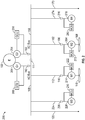
FIG. 1 is a schematic diagram depicting an example of an AC power distribution system. -
FIG. 2 is a schematic diagram depicting an example of an AC power distribution system. -
FIG. 3 is a flow diagram depicting an example of an AC power distribution method. -
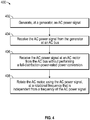
FIG. 4 is a flow diagram depicting an example of an AC power distribution method. -
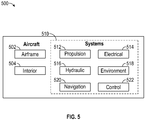
FIG. 5 is a block diagram depicting an example of an aircraft including an AC power distribution system. - While the disclosure is susceptible to various modifications and alternative forms, specific examples have been shown by way of example in the drawings and will be described in detail herein. However, it should be understood that the disclosure is not intended to be limited to the particular forms disclosed. Rather, the intention is to cover all modifications, equivalents and alternatives falling within the scope of the disclosure.
- Referring to
FIG. 1 , an example of an ACpower distribution system 100 is depicted. Thesystem 100 may include anengine 102. Theengine 102 may be an engine of a vehicle, such as an aircraft, and may provide a primary source of power for the vehicle. For example, theengine 102 may be a jet engine, a turboprop engine, a turbine engine, an internal combustion engine, another type of mechanical engine, or combinations thereof. - The
system 100 may further include afirst ISVF generator 104 and asecond ISVF generator 154. Thefirst ISVF generator 104 and thesecond ISVF generator 154 may be coupled to theengine 102 such that theengine 102 operates as a prime mover for generating electrical power signals. For example, thefirst ISVF generator 104 may receive mechanical power from theengine 102 and convert the mechanical power into a first AC power signal. Likewise, thesecond ISVF generator 154 may receive mechanical power from theengine 102 and convert the mechanical power into a second AC power signal. Although thesystem 100 is depicted have including two ISVF generators, in practice, thesystem 100 may include more or fewer than two ISVF generators. - As used herein, an ISVF generator is an AC generator that converts mechanical rotation from a prime mover into an AC power signal with a frequency that is independent from a rotational frequency of the prime mover. ISVF generators may not be reliant on gearboxes or additional AC/DC power conversions that may be applied to the AC power signal after it has left the generator to achieve an independent frequency. A background example of an ISVF generator may be found in
U.S. Patent Application No. 15/819,919, filed on November 21, 2017 first ISVF generator 104 and the second AC power signal generated by thesecond ISVF generator 154 are independent of a rotational frequency of theengine 102, they do not need to equal each other. Rather, in some cases, each of theISVF generators - In order to control the frequencies of the AC power signals, the
system 100 may include a firstgenerator control unit 106 configured to control the frequency of the AC power signal produced by thefirst ISVF generator 104 and a secondgenerator control unit 156 configured to control the frequency of the AC power signal produced by thesecond ISVF generator 154. - The system may also include a
first AC bus 108 and asecond AC bus 158. Thefirst AC bus 108 may be configured to receive the AC power signal generated by thefirst ISVF generator 104. Likewise, thesecond AC bus 158 may be configured to receive the AC power signal generated by thesecond ISVF generator 154. - In some examples, the
first AC bus 108 may be coupled to an output of thefirst ISVF generator 104 via afirst circuit breaker 110. Likewise, thesecond AC bus 158 may be coupled to an output of thesecond ISVF generator 154 via asecond circuit breaker 160. Athird circuit breaker 111 may couple thefirst AC bus 108 to thesecond AC bus 158. Thecircuit breakers system 100 to be configured in multiple states. In a first state, thecircuit breakers ISVF generators respective AC buses 108, 158). Thethird circuit breaker 111 is open (separating theAC buses 108, 158). In this configuration, each of theAC buses circuit breakers second circuit breaker 160 is open. In this configuration, thefirst ISVF generator 104 may drive both thefirst AC bus 108 and thesecond AC bus 158. As such, each of theAC buses circuit breakers first circuit breaker 110 is open. In this configuration, thesecond ISVF generator 154 may drive both thefirst AC bus 108 and thesecond AC bus 158. In a fourth state, the each of thecircuit breakers ISVF generators AC buses ISVF generators - The
system 100 may include at least one firstpower distribution line 112 to provide power from thefirst AC bus 108 to afirst AC motor 114 via afourth circuit breaker 116. Thefirst AC motor 114 may provide mechanical power to afirst propulsion system 118 such as a propeller, or other thrust generating device. Thesystem 100 may also include at least one secondpower distribution line 162 to provide power from thesecond AC bus 158 to asecond AC motor 164 via afifth circuit breaker 166. Thesecond AC motor 164 may power asecond propulsion system 168.Additional distribution lines AC buses additional distribution lines AC motors - Notably, the
system 100 is capable of functioning without performing a full-distribution-power-rated power conversion after the AC power signals are generated by theISVF generators AC motors respective buses - As used herein, a full-distribution-power-rated power conversion is a conversion of an AC power signal to a DC power signal, or a conversion of a DC power signal to an AC power signal, where substantially all of the electrical energy being distributed within the power signal (e.g., all the electrical energy generated by a generator or all the electrical energy required by a particular load) is converted. For example, full-distribution-power-rated power conversion typically relies on an intervening rectifier, inverter, motor controller, or other type of power converter, positioned between a power distribution bus and a load. In contrast, as depicted in
FIG. 1 , thefirst AC motor 114 may be coupled directly to thefirst AC bus 108 without having an intervening rectifier, inverter, motor controller, or other type of power converter, positioned therebetween. - In order to meet a frequency requirement of the
AC motors generator control units ISVF generators AC buses AC motors AC buses - During operation, the
ISVF generators engine 102 and that meet frequency requirements of theAC motors respective AC buses AC buses AC motors - A benefit of the
system 100 is that by using ISVF generators to match the frequency of the AC power signal on theAC buses AC motors system 100 may lower costs associated with the production, maintenance, and operation of the aircraft. Further, thesystem 100 is simplified as compared to typical aircraft vehicle power distribution systems and may, therefore, result in an increased lifespan. Other advantages may exist. - Referring to
FIG. 2 , an example of an ACpower distribution system 200 is depicted. Thesystem 200 may include anengine 102,circuit breakers first AC bus 108, asecond AC bus 158,power distribution lines propulsion systems system 100. - The
system 200 may further includes afirst generator 204 and asecond generator 254. Thegenerators FIG. 1 or other types of generators, such as variable speed variable frequency (VSVF) generators, constant speed constant frequency (CSCF) generators, or the like. Thefirst generator 204 and thesecond generator 254 may be coupled to theengine 102 such that theengine 102 operates as a prime mover for generating electrical power signals. For example, thefirst generator 204 may receive mechanical power from theengine 102 and convert the mechanical power into a first AC power signal. Likewise, thesecond generator 254 may receive mechanical power from theengine 102 and convert the mechanical power into a second AC power signal. Although thesystem 200 is depicted have including two generators, in practice, thesystem 200 may include more or fewer than two generators. - The
system 200 may include a firstgenerator control unit 206 and a secondgenerator control unit 256. In examples where thegenerators generator control units generators engine 102, or other factors, and thegenerator control units generators generator control units - The AC power signals generated by the
first generator 204 and thesecond generator 254 may be transmitted to thefirst AC bus 108 and thesecond AC bus 158, respectively. Thecircuit breakers system 200 to be operated in different states, providing the same configurations of power distribution on theAC buses system 100 ofFIG. 1 . - The
system 200 may include a first variable speed independent frequency (VSIF)motor 214 and asecond VSIF motor 264. Thefirst VSIF motor 214 may receive the first AC power signal from thefirst AC bus 108 and thesecond VSIF motor 264 may receive the second AC power signal from thesecond AC bus 158. - As used herein, a VSIF motor is an AC motor that converts an AC power signal into mechanical rotation with a rotational frequency that is independent from a frequency of the AC power signal. VSIF motors are not reliant on gearboxes or additional AC/DC power conversions that may be applied to the AC power signal before it powers the motor to achieve an independent rotational frequency. Rather, a VSIF motor may use multiple phases of windings on a stator and on a rotor. At least one phase on the stator may generate a rotating magnetic field configured to rotate a rotor while at least another phase on the rotor generates a second rotating magnetic field that either increases or decreases a rotational frequency of the rotor relative to the rotational frequency of the rotating magnetic field produced by the first phase. In a typical VSIF motor, three or more windings may be used to separate the rotational frequency of the rotor from the frequency of the AC signal driving the motor.
- In order to control the rotational frequencies of the
VSIF motors system 200 may include a firstmotor control unit 222 configured to control the rotational frequency of thefirst VSIF motor 214 and a secondmotor control unit 272 configured to control the rotational frequency of thesecond VSIF motor 264. - As used herein, a motor control unit differs from a motor controller used in typical vehicle electrical systems. In particular, motor controllers used in typical vehicle electrical systems rely on full-distribution-power-rated power conversions in order to drive their respective motors. In contrast, motor control units, as used herein, may perform only a partial power conversion sufficient to generate a rotating magnetic field at a set of windings attached to a rotor of a VSIF motor, while the majority of the power within an AC power signal is passed directly to the VSIF motor without any conversion. The
VSIF motors propulsion systems - The
system 200 may further include non-propulsion AC motor loads. For example, thesystem 200 may include athird distribution line 224 that provides the first AC power signal from thefirst AC bus 108 to athird VSIF motor 228 via asixth circuit breaker 226. Thethird VSIF motor 228 may be controlled by a thirdmotor control unit 230. Thesystem 200 may also include afourth distribution line 274 that provides the second AC power signal from thesecond AC bus 158 to afourth VSIF motor 278 via aseventh circuit breaker 276. Thefourth VSIF motor 278 may be controlled by a fourthmotor control unit 280. Thethird VSIF motor 228 and thefourth VSIF motor 278 may be used as part of non-propulsion systems such as ventilation systems, electrical actuation systems, other motorized systems, or combinations thereof. - During operation, the
generators respective AC buses propulsion systems system 200. From theAC buses VSIF motors motor control units VSIF motors VSIF motors propulsion systems VSIF motors - A benefit of the
system 200 is that by using VSIF motors to drive thepropulsion systems propulsion systems system 100, additional conversion elements, such as full-distribution-power-rated rectifiers and inverters may be omitted from the distribution architecture. This may result in more efficient power distribution and lighter weight. When incorporated into an aircraft vehicle, thesystem 200 may lower costs associated with the production, maintenance, and operation of the aircraft. Further, thesystem 200 is simplified as compared to typical aircraft vehicle power distribution systems and may, therefore, have an increased lifespan. Other advantages may exist. - Referring to
FIG. 3 , an example of an ACpower distribution method 300 is depicted. Themethod 300 may include generating, at an ISVF generator, an AC power signal having a frequency that is independent from a frequency of a prime mover, at 302. For example, thefirst ISVF generator 104 may generate an AC power signal that is independent of a rotational frequency of theengine 102. - The
method 300 may further include receiving the AC power signal from the ISVF generator at an AC bus, at 304. For example, the AC power signal may be received at thefirst AC bus 108. - The
method 300 may also include receiving the AC power signal at an AC load from the AC bus without performing a full-distribution-power-rated power conversion, where a frequency of the AC power signal generated by the ISVF generator meets a frequency requirement of the AC load, at 306. For example, the AC power signal may be received at thefirst AC motor 114. As depicted inFIG. 1 , the AC power signal may transmitted directly to thefirst AC motor 114 without passing through any conversion circuits. - A benefit of the
method 300 is that by using ISVF generators to match the frequency of the AC power signal on the AC buses to frequency requirements of the AC load, additional conversion elements, such as full-distribution-power-rated rectifiers and inverters may be omitted from the distribution architecture. When incorporated into an aircraft vehicle, themethod 300 may lower costs associated with the production, maintenance, and operation of the aircraft. Further, themethod 300 is simplified as compared to typical aircraft vehicle power distribution methods and may, therefore, enable an increased lifespan of the aircraft vehicle. Other advantages may exist. - Referring to
FIG. 4 , an example of an ACpower distribution method 400 is depicted. Themethod 400 may include generating, at a generator, an AC power signal, at 402. For example, thegenerator 204 may generate an AC power signal. - The
method 400 may further include receiving the AC power signal from the generator at an AC bus, at 404. For example, the AC power signal may be received at theAC bus 108. - The
method 400 may also include receiving the AC power signal at an AC motor from the AC bus without performing a full-distribution-power-rated power conversion, at 406. For example, the AC power signal may be received directly at theAC motor 214 without any intervening rectifier, inverter, motor controller, or other type of power converter performing a full-distribution-power-rated power conversion. - The
method 400 may include rotating the AC motor, using the AC power signal, at a rotational frequency that is independent from a frequency of the AC power signal, at 408. For example, theAC motor 214 may be controlled by themotor control unit 222 to operate at a frequency that is independent from the frequency of the AC power signal. - Referring to
FIG. 5 , an example of anaircraft 500 is depicted. Theaircraft 500 may include anairframe 502, an interior 504, and a plurality ofsystems 510. Examples of high-level systems 510 include one or more of apropulsion system 512, anelectrical system 514, ahydraulic system 516, anenvironmental system 518, anavigation system 520, and acontrol system 522. Any number of other systems may be included. Although an aerospace example is shown, the principles of the disclosure may be applied to other industries, such as the automotive industry. - As described herein, the
systems aircraft 500. For example, theelectrical system 514 may include theISVF generators generator control units AC buses AC motors FIG. 1 . Theelectrical system 514 may, alternatively or additionally, include thegenerators generator control units VSIF motors motor control units FIG. 2 . - Further, the disclosure comprises examples according to the following clauses:
- Clause A1: An alternating current (AC) power distribution system comprising: an independent speed variable frequency (ISVF) generator configured to generate an AC power signal having a frequency that is independent from a frequency of a prime mover; an AC bus configured to receive the AC power signal from the ISVF generator; and at least one AC load configured to receive the AC power signal from the AC bus without performing a full-distribution-power-rated power conversion, wherein the frequency of the AC power signal generated by the ISVF generator meets a frequency requirement of the AC load.
- Clause A2: The system of clause A1, wherein the AC load is an AC motor and wherein the frequency requirement of the AC load corresponds to a rotational frequency requirement of the AC motor.
- Clause A3: The system of clause A2, wherein the AC motor is incorporated into an aircraft propulsion system.
- Clause A4: The system of any of clauses A1 to A3, further comprising: a generator control unit configured to control a frequency of the AC power signal generated by the ISVF generator to meet the frequency requirement of the AC load.
- Clause A5: The system of any of clauses A1 to A4, further comprising: at least one additional AC load configured to receive the AC power signal from the AC bus.
- Clause A6: The system of any of clauses A5, wherein the at least one additional AC load has the same frequency requirement as the AC load.
- Clause A7: The system of any of clauses A1 to A6, further comprising: a second ISVF generator configured to generate a second AC power signal having a frequency that is independent from a frequency of the prime mover; a second AC bus configured to receive the second AC power signal from the second ISVF generator; and a second AC load configured to receive the second AC power signal from the second AC bus without performing a full-distribution-power-rated power conversion, wherein the frequency of the second AC power signal generated by the second ISVF generator meets a frequency requirement of the second AC load.
- Clause A8: The system of any of clauses A1 to A7, wherein the prime mover is a vehicle engine.
- Clause A9: An alternating current (AC) power distribution system comprising: a generator configured to generate an AC power signal; an AC bus configured to receive the AC power signal from the generator; an AC motor configured to receive the AC power signal from the AC bus without performing a full-distribution-power-rated power conversion, wherein the AC motor is configured to rotate at a rotational frequency that is independent from a frequency of the AC power signal; and a motor control unit configured to receive the AC power signal from the AC bus, to perform a partial power conversion of the AC power signal to generate a converted power signal, and to provide the converted power signal to the AC motor, thereby controlling the rotational frequency of the AC motor.
- Clause A10: The system of clause A9, wherein the AC motor is incorporated into an aircraft propulsion system.
- Clause A11: The system of clause A9 or A10, wherein the generator is an independent speed variable frequency (ISVF) generator, a variable speed variable frequency (VSVF) generator, or a constant speed constant frequency (CSCF) generator.
- Clause A12: The system of any of clauses A9 to A11, further comprising at least one additional AC motor configured to receive the AC power signal from the AC bus.
- Clause A13: The system of clause A12, wherein a frequency requirement of the AC motor is different than a frequency requirement of the additional AC motor.
- Clause A14: The system of clause A12 or A13, wherein the at least one additional AC motor is a non-propulsion motor load.
- Clause A15: The system of any of clauses A9 to A14, further comprising: at least one utility load configured to receive the AC power signal from the AC bus.
- Clause A16: The system of any of clauses A9 to A15, further comprising: a second generator configured to generate a second AC power signal; a second AC bus configured to receive the second AC power signal from the second generator; a second AC motor configured to receive the second AC power signal from the second AC bus without performing a full-distribution-power-rated power conversion, wherein the second AC motor is configured to rotate at a rotational frequency that is independent from a frequency of the second AC power signal; and a second motor control unit configured to receive the second AC power signal from the second AC bus, to perform a partial power conversion of the second AC power signal to generate a second converted power signal, and to provide the second converted power signal to the second AC motor, thereby controlling the rotational frequency of the second AC motor.
- Clause A17: An alternating current (AC) power distribution method comprising: generating, at an independent speed variable frequency (ISVF) generator, an AC power signal having a frequency that is independent from a frequency of a prime mover; receiving the AC power signal from the ISVF generator at an AC bus; and receiving the AC power signal at an AC load from the AC bus without performing a full-distribution-power-rated power conversion, wherein a frequency of the AC power signal generated by the ISVF generator meets a frequency requirement of the AC load.
- Clause A18: The method of clause A17, further comprising: receiving the AC power signal from the AC bus at an additional AC load, wherein the additional AC load has the same frequency requirement as the AC load.
- Clause A19: The method of clause A17 or A18, further comprising: controlling a frequency of the AC power signal generated by the ISVF generator at a generator control unit.
- Clause A20: The method of any of clauses A17 to A19, further comprising: generating, at a second ISVF generator, a second AC power signal having a frequency that is independent from a frequency of the prime mover; receiving the second AC power signal from the second ISVF generator at a second AC bus; and receiving the second AC power signal at a second AC load from the second AC bus without performing a full-distribution-power-rated power conversion, wherein the frequency of the second AC power signal generated by the second ISVF generator meets a frequency requirement of the second AC load.
- Clause A21: An alternating current (AC) power distribution method comprising: generating, at a generator, an AC power signal; receiving the AC power signal from the generator at an AC bus; receiving the AC power signal at an AC motor from the AC bus without performing a full-distribution-power-rated power conversion; and rotating the AC motor, using the AC power signal, at a rotational frequency that is independent from a frequency of the AC power signal.
- Clause A22: The method of clause A21, further comprising: receiving the AC power signal at a motor control unit; performing a partial power conversion of the AC power signal to generate a converted power signal; and providing the converted power signal to the AC motor, thereby controlling the rotational frequency of the AC motor.
- Clause A23: The method of clause A21 or A22, further comprising: receiving the AC power signal from the AC bus at an additional AC motor coupled to the AC bus; and rotating the additional AC motor, using the AC power signal, at a rotational frequency that is different from the rotational frequency of the AC motor, wherein a frequency requirement of the AC motor is different than a frequency requirement of the additional AC motor.
- Clause A24: The method of any of clauses A21 to A23, further comprising: generating, at a second generator, a second AC power signal; receiving the second AC power signal from the generator at a second AC bus; receiving the second AC power signal at a second AC motor from the second AC bus without performing a full-distribution-power-rated power conversion; and rotating the second AC motor, using the second AC power signal, at a rotational frequency that is independent from a frequency of the second AC power signal.
- Clause A25: The system of any of clauses A1 to A16, further comprising the prime mover.
- Clause A26: An aircraft propulsion system comprising the system of any of clauses A1 to A16 or A25 wherein, optionally, the AC load is an AC motor that is incorporated into an aircraft propulsion system.
- Clause A27: An aircraft comprising the aircraft propulsion system of clause A26.
- Although various examples have been shown and described, the present disclosure is not so limited and will be understood to include all such modifications and variations as would be apparent to one skilled in the art.
Claims (15)
- An alternating current power distribution system (100, 200) comprising:an independent speed variable frequency generator (104, 204) configured to generate an alternating current power signal having a frequency that is independent from a frequency of a prime mover;an alternating current bus (108) configured to receive the alternating current power signal from the independent speed variable frequency generator; andat least one alternating current load configured to receive the alternating current power signal from the alternating current bus without performing a full-distribution-power-rated power conversion, wherein the frequency of the alternating current power signal generated by the independent speed variable frequency generator meets a frequency requirement of the alternating current load.
- The system of claim 1, wherein the alternating current load is an alternating current motor (114, 164, 214, 228, 264, 278) and wherein the frequency requirement of the alternating current load corresponds to a rotational frequency requirement of the alternating current motor.
- The system of claim 2, wherein the alternating current motor is incorporated into an aircraft propulsion system (118, 168, 512).
- The system of any of claims 1-3, further comprising:
a generator control unit (106, 156, 206, 256) configured to control a frequency of the alternating current power signal generated by the independent speed variable frequency generator to meet the frequency requirement of the alternating current load. - The system of any of claims 1 to 4, further comprising:
at least one additional alternating current load configured to receive the alternating current power signal from the alternating current bus. - The system of claim 5, wherein the at least one additional alternating current load has the same frequency requirement as the alternating current load.
- The system of any of claims 1 to 6, further comprising:a second independent speed variable frequency generator (154, 254) configured to generate a second alternating current power signal having a frequency that is independent from a frequency of the prime mover;a second alternating current bus (158) configured to receive the second alternating current power signal from the second independent speed variable frequency generator; anda second alternating current load configured to receive the second alternating current power signal from the second alternating current bus without performing a full-distribution-power-rated power conversion, wherein the frequency of the second alternating current power signal generated by the second independent speed variable frequency generator meets a frequency requirement of the second alternating current load.
- The system of any of claims 1 to 7, wherein the prime mover is a vehicle engine (102).
- The system of any of claims 1 to 8, further comprising the prime mover.
- An aircraft propulsion system (118, 168, 512) comprising the system of any of claims 1 to 9 wherein, optionally, the alternating current load is an alternating current motor (114, 164, 214, 228, 264, 278) that is incorporated into an aircraft propulsion system.
- An aircraft comprising the aircraft propulsion system (118, 168, 512) of claim 10.
- An alternating current power distribution method (300, 400) comprising:generating (302, 402), at an independent speed variable frequency generator (104, 204), an alternating current power signal having a frequency that is independent from a frequency of a prime mover;receiving (304, 404) the alternating current power signal from the independent speed variable frequency generator at an alternating current bus (108); andreceiving (306, 406) the alternating current power signal at an alternating current load from the alternating current bus without performing a full-distribution-power-rated power conversion, wherein a frequency of the alternating current power signal generated by the independent speed variable frequency generator meets a frequency requirement of the alternating current load.
- The method of claim 12, further comprising:
receiving the alternating current power signal from the alternating current bus at an additional alternating current load, wherein the additional alternating current load has the same frequency requirement as the alternating current load. - The method of claim 12 or 13, further comprising:
controlling a frequency of the alternating current power signal generated by the independent speed variable frequency generator at a generator control unit (106, 156, 206, 256). - The method of any of claims 12 to 14, further comprising:generating, at a second independent speed variable frequency generator (154, 254), a second alternating current power signal having a frequency that is independent from a frequency of the prime mover;receiving the second alternating current power signal from the second independent speed variable frequency generator at a second alternating current bus (158); andreceiving the second alternating current power signal at a second alternating current load from the second alternating current bus without performing a full-distribution-power-rated power conversion, wherein the frequency of the second alternating current power signal generated by the second independent speed variable frequency generator meets a frequency requirement of the second alternating current load.
Applications Claiming Priority (1)
| Application Number | Priority Date | Filing Date | Title |
|---|---|---|---|
| US15/866,064 US10454278B2 (en) | 2018-01-09 | 2018-01-09 | Independent speed variable frequency based electrified propulsion system architecture |
Publications (2)
| Publication Number | Publication Date |
|---|---|
| EP3509209A1 true EP3509209A1 (en) | 2019-07-10 |
| EP3509209B1 EP3509209B1 (en) | 2024-08-14 |
Family
ID=64650210
Family Applications (1)
| Application Number | Title | Priority Date | Filing Date |
|---|---|---|---|
| EP18210648.4A Active EP3509209B1 (en) | 2018-01-09 | 2018-12-06 | Independent speed variable frequency based electrified propulsion system architecture |
Country Status (4)
| Country | Link |
|---|---|
| US (1) | US10454278B2 (en) |
| EP (1) | EP3509209B1 (en) |
| JP (1) | JP7281282B2 (en) |
| CN (1) | CN110015433B (en) |
Cited By (1)
| Publication number | Priority date | Publication date | Assignee | Title |
|---|---|---|---|---|
| CN120890713A (en) * | 2025-09-30 | 2025-11-04 | 东方电气集团东方电机有限公司 | A frequency conversion motor-generator test system and method |
Families Citing this family (3)
| Publication number | Priority date | Publication date | Assignee | Title |
|---|---|---|---|---|
| US10868483B1 (en) * | 2019-06-03 | 2020-12-15 | Hamilton Sundstrand Corporation | DC generator system |
| US11325714B2 (en) * | 2020-07-09 | 2022-05-10 | General Electric Company | Electric power system for a vehicle |
| TWI848668B (en) * | 2023-04-25 | 2024-07-11 | 陳錫瑜 | Improvement device for dual-motor automatic switching switch |
Family Cites Families (21)
| Publication number | Priority date | Publication date | Assignee | Title |
|---|---|---|---|---|
| US2896143A (en) | 1957-03-11 | 1959-07-21 | Genisco Inc | Electric drive assembly |
| US4625160A (en) | 1984-12-17 | 1986-11-25 | Sundstrand Corporation | Variable speed constant frequency generating system |
| US4772802A (en) | 1987-08-19 | 1988-09-20 | Sundstrand Corporation | Starting/generating system |
| US4868406A (en) | 1988-07-05 | 1989-09-19 | Sundstrand Corporation | Electrically compensated constant speed drive with prime mover start capability |
| US5036267A (en) | 1989-12-15 | 1991-07-30 | Sundstrand Corporation | Aircraft turbine start from a low voltage battery |
| US5068590A (en) | 1989-12-20 | 1991-11-26 | Sundstrand Corporation | Brushless generator having AC excitation in generating and starting modes |
| US5581168A (en) | 1993-05-12 | 1996-12-03 | Sundstrand Corporation | Starter/generator system with DC link current control |
| US6462429B1 (en) | 2000-02-24 | 2002-10-08 | Hamilton Sundstrand Corporation | Induction motor/generator system |
| GB0227461D0 (en) | 2002-11-25 | 2002-12-31 | Goodrich Control Sys Ltd | A method of and apparatus for detecting sensor loss in a generator control system |
| US8299762B2 (en) | 2009-06-05 | 2012-10-30 | Hamilton Sundstrand Corporation | Starting/generating system with multi-functional circuit breaker |
| FR2952130B1 (en) | 2009-10-30 | 2018-09-07 | Safran Electrical & Power | TURBOMACHINE GENERATOR STARTER AND METHOD FOR CONTROLLING THE SAME. |
| DE102010040455A1 (en) | 2010-09-09 | 2012-03-15 | Zf Friedrichshafen Ag | Method for operating a drive train |
| US8593095B2 (en) | 2011-05-24 | 2013-11-26 | Hamilton Sundstrand Corporation | Wound field synchronous machine rotor tracking using a carrier injection sensorless signal and exciter current |
| EP2682339B1 (en) * | 2012-07-06 | 2022-06-15 | GE Energy Power Conversion Technology Ltd | Power distribution systems |
| US9325229B2 (en) | 2013-03-15 | 2016-04-26 | Hamilton Sundstrand Corporation | Generator architecture with PMG exciter and main field rotating power converter |
| CN105452613B (en) * | 2013-06-06 | 2019-04-30 | 通用电气航空系统有限责任公司 | Jet engine assembly and method of generating electricity |
| US9209741B2 (en) | 2014-02-24 | 2015-12-08 | The Boeing Company | Method and system for controlling synchronous machine as generator/starter |
| EP3016227B1 (en) * | 2014-10-27 | 2017-03-01 | ABB Schweiz AG | Electric power generating system |
| JP6730842B2 (en) * | 2015-05-05 | 2020-07-29 | ロールス−ロイス コーポレイション | Electric direct drive for aircraft propulsion and lift |
| US20160365814A1 (en) * | 2015-06-09 | 2016-12-15 | Hamilton Sundstrand Corporation | Variable speed ac generator system including independently controlled rotor field |
| EP3104519B1 (en) * | 2015-06-11 | 2021-08-04 | Rolls-Royce North American Technologies, Inc. | Varying quantities of motor poles for noise reduction |
-
2018
- 2018-01-09 US US15/866,064 patent/US10454278B2/en active Active
- 2018-11-30 CN CN201811453360.1A patent/CN110015433B/en active Active
- 2018-12-06 EP EP18210648.4A patent/EP3509209B1/en active Active
-
2019
- 2019-01-07 JP JP2019000585A patent/JP7281282B2/en active Active
Non-Patent Citations (1)
| Title |
|---|
| K. M. CHIRGWIN ET AL: "VARIABLE SPEED CONSTANT FREQUENCY GENERATOR SYSTEM FOR AIRCRAFT", IEEE JOURNALS & MAGZINE, 30 November 1959 (1959-11-30), pages 304 - 310, XP055589918, Retrieved from the Internet <URL:https://ieeexplore.ieee.org/ielx5/6366379/6369047/06369055.pdf?tp=&arnumber=6369055&isnumber=6369047&ref=aHR0cHM6Ly9pZWVleHBsb3JlLmllZWUub3JnL2RvY3VtZW50LzYzNjkwNTU=> [retrieved on 20190520] * |
Cited By (1)
| Publication number | Priority date | Publication date | Assignee | Title |
|---|---|---|---|---|
| CN120890713A (en) * | 2025-09-30 | 2025-11-04 | 东方电气集团东方电机有限公司 | A frequency conversion motor-generator test system and method |
Also Published As
| Publication number | Publication date |
|---|---|
| CN110015433A (en) | 2019-07-16 |
| EP3509209B1 (en) | 2024-08-14 |
| CN110015433B (en) | 2024-12-13 |
| JP2019165619A (en) | 2019-09-26 |
| US20190214828A1 (en) | 2019-07-11 |
| JP7281282B2 (en) | 2023-05-25 |
| US10454278B2 (en) | 2019-10-22 |
Similar Documents
| Publication | Publication Date | Title |
|---|---|---|
| US7638890B2 (en) | Device for supplying electrical power to an aircraft and for electrically starting a jet engine on board an aircraft | |
| US6778414B2 (en) | Distributed system and methodology of electrical power regulation, conditioning and distribution on an aircraft | |
| US9963095B2 (en) | Electrical power system for an aircraft | |
| US20200025094A1 (en) | Method for allocating power in an electrical power system architecture | |
| EP3296212B1 (en) | Aircraft propulsion system | |
| US12565854B2 (en) | Hybrid propulsion turboprop engine coupled to a propeller and aircraft comprising such a turboprop engine | |
| RU2641672C1 (en) | Control and electrical supply system for helicopter gas turbine engines | |
| EP2416475B1 (en) | Electric power generating system with boost converter/synchronous active filter | |
| EP0536876B1 (en) | Electric power system for marine vehicles | |
| US7439634B2 (en) | Electrical starting, generation, conversion and distribution system architecture for a more electric vehicle | |
| US11110811B2 (en) | Thin haul hybrid electric propulsion system | |
| Zhang et al. | Overview and development of variable frequency AC generators for more electric aircraft generation system | |
| US8928171B2 (en) | Power distribution device for distributing power and a method for the distribution of power | |
| US7459889B2 (en) | DC bus short circuit compliant power generation systems using induction machine | |
| CN110015433B (en) | AC power distribution system and AC power distribution method | |
| US8218341B2 (en) | Integrated aircraft power conditioning unit | |
| EP3375981A1 (en) | Variable speed ac bus powered tail cone boundary layer ingestion thruster | |
| CN101636901A (en) | Power Generation Systems with Multiple Generators and/or Inverters | |
| WO1988006378A1 (en) | Power generating system | |
| JP2010507526A (en) | Systems for power generation, conversion, distribution and start-up onboard aircraft | |
| US20250192699A1 (en) | Electric drive system | |
| US7369417B2 (en) | Method and system for producing controlled frequency power from a variable frequency power source | |
| EP3621170B1 (en) | Hvdc power supply system | |
| RU150254U1 (en) | DC POWER SUPPLY OF AUTONOMOUS VEHICLE VEHICLE | |
| RU2573576C2 (en) | Dc power supply device for self-contained transport vehicle |
Legal Events
| Date | Code | Title | Description |
|---|---|---|---|
| PUAI | Public reference made under article 153(3) epc to a published international application that has entered the european phase |
Free format text: ORIGINAL CODE: 0009012 |
|
| STAA | Information on the status of an ep patent application or granted ep patent |
Free format text: STATUS: REQUEST FOR EXAMINATION WAS MADE |
|
| 17P | Request for examination filed |
Effective date: 20181206 |
|
| AK | Designated contracting states |
Kind code of ref document: A1 Designated state(s): AL AT BE BG CH CY CZ DE DK EE ES FI FR GB GR HR HU IE IS IT LI LT LU LV MC MK MT NL NO PL PT RO RS SE SI SK SM TR |
|
| AX | Request for extension of the european patent |
Extension state: BA ME |
|
| STAA | Information on the status of an ep patent application or granted ep patent |
Free format text: STATUS: EXAMINATION IS IN PROGRESS |
|
| 17Q | First examination report despatched |
Effective date: 20200602 |
|
| RAP3 | Party data changed (applicant data changed or rights of an application transferred) |
Owner name: THE BOEING COMPANY |
|
| GRAP | Despatch of communication of intention to grant a patent |
Free format text: ORIGINAL CODE: EPIDOSNIGR1 |
|
| STAA | Information on the status of an ep patent application or granted ep patent |
Free format text: STATUS: GRANT OF PATENT IS INTENDED |
|
| INTG | Intention to grant announced |
Effective date: 20231024 |
|
| P01 | Opt-out of the competence of the unified patent court (upc) registered |
Effective date: 20231101 |
|
| GRAJ | Information related to disapproval of communication of intention to grant by the applicant or resumption of examination proceedings by the epo deleted |
Free format text: ORIGINAL CODE: EPIDOSDIGR1 |
|
| STAA | Information on the status of an ep patent application or granted ep patent |
Free format text: STATUS: EXAMINATION IS IN PROGRESS |
|
| GRAP | Despatch of communication of intention to grant a patent |
Free format text: ORIGINAL CODE: EPIDOSNIGR1 |
|
| STAA | Information on the status of an ep patent application or granted ep patent |
Free format text: STATUS: GRANT OF PATENT IS INTENDED |
|
| INTC | Intention to grant announced (deleted) | ||
| INTG | Intention to grant announced |
Effective date: 20240315 |
|
| GRAS | Grant fee paid |
Free format text: ORIGINAL CODE: EPIDOSNIGR3 |
|
| GRAA | (expected) grant |
Free format text: ORIGINAL CODE: 0009210 |
|
| STAA | Information on the status of an ep patent application or granted ep patent |
Free format text: STATUS: THE PATENT HAS BEEN GRANTED |
|
| AK | Designated contracting states |
Kind code of ref document: B1 Designated state(s): AL AT BE BG CH CY CZ DE DK EE ES FI FR GB GR HR HU IE IS IT LI LT LU LV MC MK MT NL NO PL PT RO RS SE SI SK SM TR |
|
| REG | Reference to a national code |
Ref country code: GB Ref legal event code: FG4D |
|
| REG | Reference to a national code |
Ref country code: CH Ref legal event code: EP |
|
| REG | Reference to a national code |
Ref country code: DE Ref legal event code: R096 Ref document number: 602018073026 Country of ref document: DE |
|
| REG | Reference to a national code |
Ref country code: IE Ref legal event code: FG4D |
|
| REG | Reference to a national code |
Ref country code: LT Ref legal event code: MG9D |
|
| REG | Reference to a national code |
Ref country code: NL Ref legal event code: MP Effective date: 20240814 |
|
| PG25 | Lapsed in a contracting state [announced via postgrant information from national office to epo] |
Ref country code: NO Free format text: LAPSE BECAUSE OF FAILURE TO SUBMIT A TRANSLATION OF THE DESCRIPTION OR TO PAY THE FEE WITHIN THE PRESCRIBED TIME-LIMIT Effective date: 20241114 |
|
| REG | Reference to a national code |
Ref country code: AT Ref legal event code: MK05 Ref document number: 1714209 Country of ref document: AT Kind code of ref document: T Effective date: 20240814 |
|
| PG25 | Lapsed in a contracting state [announced via postgrant information from national office to epo] |
Ref country code: GR Free format text: LAPSE BECAUSE OF FAILURE TO SUBMIT A TRANSLATION OF THE DESCRIPTION OR TO PAY THE FEE WITHIN THE PRESCRIBED TIME-LIMIT Effective date: 20241115 Ref country code: NL Free format text: LAPSE BECAUSE OF FAILURE TO SUBMIT A TRANSLATION OF THE DESCRIPTION OR TO PAY THE FEE WITHIN THE PRESCRIBED TIME-LIMIT Effective date: 20240814 Ref country code: PL Free format text: LAPSE BECAUSE OF FAILURE TO SUBMIT A TRANSLATION OF THE DESCRIPTION OR TO PAY THE FEE WITHIN THE PRESCRIBED TIME-LIMIT Effective date: 20240814 Ref country code: PT Free format text: LAPSE BECAUSE OF FAILURE TO SUBMIT A TRANSLATION OF THE DESCRIPTION OR TO PAY THE FEE WITHIN THE PRESCRIBED TIME-LIMIT Effective date: 20241216 Ref country code: FI Free format text: LAPSE BECAUSE OF FAILURE TO SUBMIT A TRANSLATION OF THE DESCRIPTION OR TO PAY THE FEE WITHIN THE PRESCRIBED TIME-LIMIT Effective date: 20240814 |
|
| PG25 | Lapsed in a contracting state [announced via postgrant information from national office to epo] |
Ref country code: BG Free format text: LAPSE BECAUSE OF FAILURE TO SUBMIT A TRANSLATION OF THE DESCRIPTION OR TO PAY THE FEE WITHIN THE PRESCRIBED TIME-LIMIT Effective date: 20240814 |
|
| PG25 | Lapsed in a contracting state [announced via postgrant information from national office to epo] |
Ref country code: LV Free format text: LAPSE BECAUSE OF FAILURE TO SUBMIT A TRANSLATION OF THE DESCRIPTION OR TO PAY THE FEE WITHIN THE PRESCRIBED TIME-LIMIT Effective date: 20240814 |
|
| PG25 | Lapsed in a contracting state [announced via postgrant information from national office to epo] |
Ref country code: AT Free format text: LAPSE BECAUSE OF FAILURE TO SUBMIT A TRANSLATION OF THE DESCRIPTION OR TO PAY THE FEE WITHIN THE PRESCRIBED TIME-LIMIT Effective date: 20240814 Ref country code: IS Free format text: LAPSE BECAUSE OF FAILURE TO SUBMIT A TRANSLATION OF THE DESCRIPTION OR TO PAY THE FEE WITHIN THE PRESCRIBED TIME-LIMIT Effective date: 20241214 |
|
| PG25 | Lapsed in a contracting state [announced via postgrant information from national office to epo] |
Ref country code: HR Free format text: LAPSE BECAUSE OF FAILURE TO SUBMIT A TRANSLATION OF THE DESCRIPTION OR TO PAY THE FEE WITHIN THE PRESCRIBED TIME-LIMIT Effective date: 20240814 |
|
| PG25 | Lapsed in a contracting state [announced via postgrant information from national office to epo] |
Ref country code: RS Free format text: LAPSE BECAUSE OF FAILURE TO SUBMIT A TRANSLATION OF THE DESCRIPTION OR TO PAY THE FEE WITHIN THE PRESCRIBED TIME-LIMIT Effective date: 20241114 Ref country code: ES Free format text: LAPSE BECAUSE OF FAILURE TO SUBMIT A TRANSLATION OF THE DESCRIPTION OR TO PAY THE FEE WITHIN THE PRESCRIBED TIME-LIMIT Effective date: 20240814 |
|
| PG25 | Lapsed in a contracting state [announced via postgrant information from national office to epo] |
Ref country code: RS Free format text: LAPSE BECAUSE OF FAILURE TO SUBMIT A TRANSLATION OF THE DESCRIPTION OR TO PAY THE FEE WITHIN THE PRESCRIBED TIME-LIMIT Effective date: 20241114 Ref country code: PT Free format text: LAPSE BECAUSE OF FAILURE TO SUBMIT A TRANSLATION OF THE DESCRIPTION OR TO PAY THE FEE WITHIN THE PRESCRIBED TIME-LIMIT Effective date: 20241216 Ref country code: PL Free format text: LAPSE BECAUSE OF FAILURE TO SUBMIT A TRANSLATION OF THE DESCRIPTION OR TO PAY THE FEE WITHIN THE PRESCRIBED TIME-LIMIT Effective date: 20240814 Ref country code: NO Free format text: LAPSE BECAUSE OF FAILURE TO SUBMIT A TRANSLATION OF THE DESCRIPTION OR TO PAY THE FEE WITHIN THE PRESCRIBED TIME-LIMIT Effective date: 20241114 Ref country code: NL Free format text: LAPSE BECAUSE OF FAILURE TO SUBMIT A TRANSLATION OF THE DESCRIPTION OR TO PAY THE FEE WITHIN THE PRESCRIBED TIME-LIMIT Effective date: 20240814 Ref country code: LV Free format text: LAPSE BECAUSE OF FAILURE TO SUBMIT A TRANSLATION OF THE DESCRIPTION OR TO PAY THE FEE WITHIN THE PRESCRIBED TIME-LIMIT Effective date: 20240814 Ref country code: IS Free format text: LAPSE BECAUSE OF FAILURE TO SUBMIT A TRANSLATION OF THE DESCRIPTION OR TO PAY THE FEE WITHIN THE PRESCRIBED TIME-LIMIT Effective date: 20241214 Ref country code: HR Free format text: LAPSE BECAUSE OF FAILURE TO SUBMIT A TRANSLATION OF THE DESCRIPTION OR TO PAY THE FEE WITHIN THE PRESCRIBED TIME-LIMIT Effective date: 20240814 Ref country code: GR Free format text: LAPSE BECAUSE OF FAILURE TO SUBMIT A TRANSLATION OF THE DESCRIPTION OR TO PAY THE FEE WITHIN THE PRESCRIBED TIME-LIMIT Effective date: 20241115 Ref country code: FI Free format text: LAPSE BECAUSE OF FAILURE TO SUBMIT A TRANSLATION OF THE DESCRIPTION OR TO PAY THE FEE WITHIN THE PRESCRIBED TIME-LIMIT Effective date: 20240814 Ref country code: ES Free format text: LAPSE BECAUSE OF FAILURE TO SUBMIT A TRANSLATION OF THE DESCRIPTION OR TO PAY THE FEE WITHIN THE PRESCRIBED TIME-LIMIT Effective date: 20240814 Ref country code: BG Free format text: LAPSE BECAUSE OF FAILURE TO SUBMIT A TRANSLATION OF THE DESCRIPTION OR TO PAY THE FEE WITHIN THE PRESCRIBED TIME-LIMIT Effective date: 20240814 Ref country code: AT Free format text: LAPSE BECAUSE OF FAILURE TO SUBMIT A TRANSLATION OF THE DESCRIPTION OR TO PAY THE FEE WITHIN THE PRESCRIBED TIME-LIMIT Effective date: 20240814 |
|
| PG25 | Lapsed in a contracting state [announced via postgrant information from national office to epo] |
Ref country code: SM Free format text: LAPSE BECAUSE OF FAILURE TO SUBMIT A TRANSLATION OF THE DESCRIPTION OR TO PAY THE FEE WITHIN THE PRESCRIBED TIME-LIMIT Effective date: 20240814 Ref country code: DK Free format text: LAPSE BECAUSE OF FAILURE TO SUBMIT A TRANSLATION OF THE DESCRIPTION OR TO PAY THE FEE WITHIN THE PRESCRIBED TIME-LIMIT Effective date: 20240814 Ref country code: RO Free format text: LAPSE BECAUSE OF FAILURE TO SUBMIT A TRANSLATION OF THE DESCRIPTION OR TO PAY THE FEE WITHIN THE PRESCRIBED TIME-LIMIT Effective date: 20240814 |
|
| PG25 | Lapsed in a contracting state [announced via postgrant information from national office to epo] |
Ref country code: EE Free format text: LAPSE BECAUSE OF FAILURE TO SUBMIT A TRANSLATION OF THE DESCRIPTION OR TO PAY THE FEE WITHIN THE PRESCRIBED TIME-LIMIT Effective date: 20240814 |
|
| PG25 | Lapsed in a contracting state [announced via postgrant information from national office to epo] |
Ref country code: CZ Free format text: LAPSE BECAUSE OF FAILURE TO SUBMIT A TRANSLATION OF THE DESCRIPTION OR TO PAY THE FEE WITHIN THE PRESCRIBED TIME-LIMIT Effective date: 20240814 |
|
| PG25 | Lapsed in a contracting state [announced via postgrant information from national office to epo] |
Ref country code: IT Free format text: LAPSE BECAUSE OF FAILURE TO SUBMIT A TRANSLATION OF THE DESCRIPTION OR TO PAY THE FEE WITHIN THE PRESCRIBED TIME-LIMIT Effective date: 20240814 Ref country code: SK Free format text: LAPSE BECAUSE OF FAILURE TO SUBMIT A TRANSLATION OF THE DESCRIPTION OR TO PAY THE FEE WITHIN THE PRESCRIBED TIME-LIMIT Effective date: 20240814 |
|
| REG | Reference to a national code |
Ref country code: DE Ref legal event code: R097 Ref document number: 602018073026 Country of ref document: DE |
|
| PLBE | No opposition filed within time limit |
Free format text: ORIGINAL CODE: 0009261 |
|
| STAA | Information on the status of an ep patent application or granted ep patent |
Free format text: STATUS: NO OPPOSITION FILED WITHIN TIME LIMIT |
|
| PG25 | Lapsed in a contracting state [announced via postgrant information from national office to epo] |
Ref country code: MC Free format text: LAPSE BECAUSE OF FAILURE TO SUBMIT A TRANSLATION OF THE DESCRIPTION OR TO PAY THE FEE WITHIN THE PRESCRIBED TIME-LIMIT Effective date: 20240814 |
|
| 26N | No opposition filed |
Effective date: 20250515 |
|
| REG | Reference to a national code |
Ref country code: CH Ref legal event code: PL |
|
| PG25 | Lapsed in a contracting state [announced via postgrant information from national office to epo] |
Ref country code: LU Free format text: LAPSE BECAUSE OF NON-PAYMENT OF DUE FEES Effective date: 20241206 |
|
| PG25 | Lapsed in a contracting state [announced via postgrant information from national office to epo] |
Ref country code: SE Free format text: LAPSE BECAUSE OF FAILURE TO SUBMIT A TRANSLATION OF THE DESCRIPTION OR TO PAY THE FEE WITHIN THE PRESCRIBED TIME-LIMIT Effective date: 20240814 |
|
| REG | Reference to a national code |
Ref country code: BE Ref legal event code: MM Effective date: 20241231 |
|
| PG25 | Lapsed in a contracting state [announced via postgrant information from national office to epo] |
Ref country code: BE Free format text: LAPSE BECAUSE OF NON-PAYMENT OF DUE FEES Effective date: 20241231 |
|
| PG25 | Lapsed in a contracting state [announced via postgrant information from national office to epo] |
Ref country code: CH Free format text: LAPSE BECAUSE OF NON-PAYMENT OF DUE FEES Effective date: 20241231 |
|
| PG25 | Lapsed in a contracting state [announced via postgrant information from national office to epo] |
Ref country code: IE Free format text: LAPSE BECAUSE OF NON-PAYMENT OF DUE FEES Effective date: 20241206 |
|
| PGFP | Annual fee paid to national office [announced via postgrant information from national office to epo] |
Ref country code: GB Payment date: 20251229 Year of fee payment: 8 |
|
| PGFP | Annual fee paid to national office [announced via postgrant information from national office to epo] |
Ref country code: FR Payment date: 20251226 Year of fee payment: 8 |
|
| PG25 | Lapsed in a contracting state [announced via postgrant information from national office to epo] |
Ref country code: CY Free format text: LAPSE BECAUSE OF FAILURE TO SUBMIT A TRANSLATION OF THE DESCRIPTION OR TO PAY THE FEE WITHIN THE PRESCRIBED TIME-LIMIT; INVALID AB INITIO Effective date: 20181206 |
|
| PGFP | Annual fee paid to national office [announced via postgrant information from national office to epo] |
Ref country code: DE Payment date: 20251229 Year of fee payment: 8 |