EP3509188A1 - Electric generator including a stator end plate - Google Patents
Electric generator including a stator end plate Download PDFInfo
- Publication number
- EP3509188A1 EP3509188A1 EP18150800.3A EP18150800A EP3509188A1 EP 3509188 A1 EP3509188 A1 EP 3509188A1 EP 18150800 A EP18150800 A EP 18150800A EP 3509188 A1 EP3509188 A1 EP 3509188A1
- Authority
- EP
- European Patent Office
- Prior art keywords
- stator
- electric generator
- drive end
- plate
- stator body
- Prior art date
- Legal status (The legal status is an assumption and is not a legal conclusion. Google has not performed a legal analysis and makes no representation as to the accuracy of the status listed.)
- Granted
Links
Images

Classifications
-
- H—ELECTRICITY
- H02—GENERATION; CONVERSION OR DISTRIBUTION OF ELECTRIC POWER
- H02K—DYNAMO-ELECTRIC MACHINES
- H02K3/00—Details of windings
- H02K3/42—Means for preventing or reducing eddy-current losses in the winding heads, e.g. by shielding
-
- F—MECHANICAL ENGINEERING; LIGHTING; HEATING; WEAPONS; BLASTING
- F03—MACHINES OR ENGINES FOR LIQUIDS; WIND, SPRING, OR WEIGHT MOTORS; PRODUCING MECHANICAL POWER OR A REACTIVE PROPULSIVE THRUST, NOT OTHERWISE PROVIDED FOR
- F03D—WIND MOTORS
- F03D9/00—Adaptations of wind motors for special use; Combinations of wind motors with apparatus driven thereby; Wind motors specially adapted for installation in particular locations
- F03D9/20—Wind motors characterised by the driven apparatus
- F03D9/25—Wind motors characterised by the driven apparatus the apparatus being an electrical generator
-
- H—ELECTRICITY
- H02—GENERATION; CONVERSION OR DISTRIBUTION OF ELECTRIC POWER
- H02K—DYNAMO-ELECTRIC MACHINES
- H02K1/00—Details of the magnetic circuit
- H02K1/06—Details of the magnetic circuit characterised by the shape, form or construction
- H02K1/12—Stationary parts of the magnetic circuit
- H02K1/18—Means for mounting or fastening magnetic stationary parts on to, or to, the stator structures
- H02K1/185—Means for mounting or fastening magnetic stationary parts on to, or to, the stator structures to outer stators
-
- H—ELECTRICITY
- H02—GENERATION; CONVERSION OR DISTRIBUTION OF ELECTRIC POWER
- H02K—DYNAMO-ELECTRIC MACHINES
- H02K1/00—Details of the magnetic circuit
- H02K1/06—Details of the magnetic circuit characterised by the shape, form or construction
- H02K1/12—Stationary parts of the magnetic circuit
- H02K1/18—Means for mounting or fastening magnetic stationary parts on to, or to, the stator structures
- H02K1/187—Means for mounting or fastening magnetic stationary parts on to, or to, the stator structures to inner stators
-
- H—ELECTRICITY
- H02—GENERATION; CONVERSION OR DISTRIBUTION OF ELECTRIC POWER
- H02K—DYNAMO-ELECTRIC MACHINES
- H02K21/00—Synchronous motors having permanent magnets; Synchronous generators having permanent magnets
- H02K21/12—Synchronous motors having permanent magnets; Synchronous generators having permanent magnets with stationary armatures and rotating magnets
- H02K21/14—Synchronous motors having permanent magnets; Synchronous generators having permanent magnets with stationary armatures and rotating magnets with magnets rotating within the armatures
-
- H—ELECTRICITY
- H02—GENERATION; CONVERSION OR DISTRIBUTION OF ELECTRIC POWER
- H02K—DYNAMO-ELECTRIC MACHINES
- H02K7/00—Arrangements for handling mechanical energy structurally associated with dynamo-electric machines, e.g. structural association with mechanical driving motors or auxiliary dynamo-electric machines
- H02K7/18—Structural association of electric generators with mechanical driving motors, e.g. with turbines
- H02K7/1807—Rotary generators
- H02K7/1823—Rotary generators structurally associated with turbines or similar engines
- H02K7/183—Rotary generators structurally associated with turbines or similar engines wherein the turbine is a wind turbine
- H02K7/1838—Generators mounted in a nacelle or similar structure of a horizontal axis wind turbine
-
- F—MECHANICAL ENGINEERING; LIGHTING; HEATING; WEAPONS; BLASTING
- F05—INDEXING SCHEMES RELATING TO ENGINES OR PUMPS IN VARIOUS SUBCLASSES OF CLASSES F01-F04
- F05B—INDEXING SCHEME RELATING TO WIND, SPRING, WEIGHT, INERTIA OR LIKE MOTORS, TO MACHINES OR ENGINES FOR LIQUIDS COVERED BY SUBCLASSES F03B, F03D AND F03G
- F05B2220/00—Application
- F05B2220/70—Application in combination with
- F05B2220/706—Application in combination with an electrical generator
- F05B2220/7068—Application in combination with an electrical generator equipped with permanent magnets
-
- H—ELECTRICITY
- H02—GENERATION; CONVERSION OR DISTRIBUTION OF ELECTRIC POWER
- H02K—DYNAMO-ELECTRIC MACHINES
- H02K2201/00—Specific aspects not provided for in the other groups of this subclass relating to the magnetic circuits
- H02K2201/06—Magnetic cores, or permanent magnets characterised by their skew
-
- Y—GENERAL TAGGING OF NEW TECHNOLOGICAL DEVELOPMENTS; GENERAL TAGGING OF CROSS-SECTIONAL TECHNOLOGIES SPANNING OVER SEVERAL SECTIONS OF THE IPC; TECHNICAL SUBJECTS COVERED BY FORMER USPC CROSS-REFERENCE ART COLLECTIONS [XRACs] AND DIGESTS
- Y02—TECHNOLOGIES OR APPLICATIONS FOR MITIGATION OR ADAPTATION AGAINST CLIMATE CHANGE
- Y02E—REDUCTION OF GREENHOUSE GAS [GHG] EMISSIONS, RELATED TO ENERGY GENERATION, TRANSMISSION OR DISTRIBUTION
- Y02E10/00—Energy generation through renewable energy sources
- Y02E10/70—Wind energy
- Y02E10/72—Wind turbines with rotation axis in wind direction
Definitions
- the present invention relates to an electric generator including a stator end plate. Particularly, but not exclusively, the present invention may be efficiently applied to an electric generator of a wind turbine.
- An electric generator such as an electric generator installed in a wind turbine, typically comprises a rotor which rotates relative to a stator.
- the electric generator extends axially between a drive end (DE), connected to the driving device (i.e. the rotor with blades of the wind turbine) and an axially opposite non-drive end (NDE).
- the stator normally comprises a frame body longitudinally extending along a longitudinal axis and including a stator yoke and a plurality of teeth protruding according to a radial direction from the stator yoke to respective tooth radial ends. Each tooth extends also longitudinally between a first tooth longitudinal end and a second tooth longitudinal end.
- each slot being delimited circumferentially by two adjacent teeth and radially extending between the stator yoke and the respective tooth radial ends.
- Each slot houses a respective winding.
- End plates are typically provided at the teeth longitudinal ends, both at the drive end and the non-drive end. The end plates mechanically support the stator lamination and in particular the teeth during manufacturing and operation. The end plates have a typical finger shape for following the shape of the stator teeth.
- Such finger plates are normally laminated and made of mild steel and are characterized by eddy current losses leading to lower rated power and efficiency (in particular a lower AEP, Annual Energy Production).
- Another inconvenience of the finger plates is that they are expensive to manufacture.
- the finger plates may be made of stainless steel.
- the cost (material and manufacturing) of such option is significant high.
- Another option is to laminate the finger plate with a layer of glue between the laminations, which constitute them. Such technique however is not particularly efficient, permitting to achieve finger plates, which are not as strong as desired. Further, the gluing is excessively expensive to implement, needing a clear environments, a pressing mechanism and other devices.
- the stator comprises:
- the stator support includes a shoulder at the non-drive end for axially supporting the stator body.
- the end plate is finger-shaped, the end plate including a plate yoke adjacent to the stator yoke and a plurality of stator teeth protruding from the plate yoke according to the radial direction and respectively adjacent to the teeth of the stator body.
- the stator body or the end plate may include a plurality of laminations stacked along the longitudinal axis of the stator.
- the present application proposes a single end plate design, where only an end plate at the low losses end, i.e. the drive end, is used to provide mechanical support and at the same time contributed with a reduced amount of eddy-current losses.
- the end plate at the other end i.e. non-drive end
- this further contributes in reducing the eddy-current losses caused by the presence of any finger plate.
- FIG. 1 shows a wind turbine 1 according to the invention.
- the wind turbine 1 comprises a tower 2, which is mounted on a non-depicted fundament.
- a nacelle 3 is arranged on top of the tower 2.
- the wind turbine 1 further comprises a wind rotor 5 having two, three or more blades 4 (in the perspective of Figure 1 only two blades 4 are visible).
- the wind rotor 5 is rotatable around a rotational axis Y.
- the terms axial, radial and circumferential in the following are made with reference to the rotational axis Y.
- the blades 4 extend radially with respect to the rotational axis Y.
- the wind turbine 1 comprises a permanent magnet electric generator 10.
- the present invention may be applied to any other type of permanent magnet machine with either internal or external rotor 12.
- the wind rotor 5 is rotationally coupled with the permanent magnet generator 10 either directly, e.g. direct drive or by means of a rotatable main shaft 9 and through a gear box (not shown in Figure 1 ).
- a schematically depicted bearing assembly 8 is provided in order to hold in place the rotor 5.
- the rotatable main shaft 9 extends along the rotational axis Y.
- the permanent magnet electric generator 10 extends longitudinally between a drive end 31 connected to the wind rotor 5 and an opposite non-drive end 32.
- the permanent magnet electric generator 10 includes a stator 11 and a rotor 12.
- the rotor 12 is rotatable with respect to the stator 11 about the rotational axis Y.
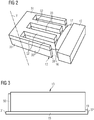
- Figure 2 shows a more detailed view of the stator 11 and the rotor 12 of the electrical generator 10.
- the rotor 12 is radially external with respect the stator 11.
- a plurality of permanent magnets 17 (only one permanent magnet 17 is shown in figure 2 ) are attached on a face of the rotor 12 facing the stator 11.
- the magnets 17 on the rotor 12 may be skewed with respect to the longitudinal axis Y.
- An air gap 16, which extends circumferential around the axis Y, is provided between the rotor 12 and the stator 11 and in particular between the permanent magnets 17 and the stator 11.
- the rotor 12 and the permanent magnets 17 are not a specific part of the present invention and therefore not described in further detail.
- the present invention can be therefore adapted to electrical generators with or without permanent magnets.
- the stator 11 comprises a stator body 13 longitudinally extending along the longitudinal axis.
- the stator 11 has a conventional lamination structure including a plurality of laminations 18 stacked along the longitudinal axis Y.
- the stator body 13 includes a stator yoke 22 and a plurality of teeth 33 protruding according to a radial direction orthogonal to the longitudinal axis Y from the stator yoke 22 to respective tooth radial ends 38, each tooth extending longitudinally between the drive end 31 and the non-drive end 32.
- the teeth 33 may be skewed with respect to the longitudinal axis Y.
- the stator 11 further comprises a stator support 15 for radially supporting the stator body 13.
- the stator support 15 further provides an axial support to the stator body 13 at the non-drive end 32.
- a shoulder 19 extending circumferentially and protruding radially from the stator support 15 is provided at the non-drive end 32 for axially supporting the plurality of laminations 18 of the stator body 13.
- the stator 10 further comprises an end plate 50 for axially supporting the plurality of laminations 18 of the stator body 11 at the drive end 31.
- the end plate 50 is finger-shaped, the end plate 50 including a plate yoke 51 adjacent to the stator yoke 12 and a plurality of plate teeth 52 protruding from the plate yoke 22 according to the radial direction.
- Each plate tooth 52 of the end plate 50 is adjacent to a respective tooth 33 of the stator body 13, for providing an efficient support.
- the end plate 50 similarly to the stator body 13, includes a plurality of plate laminations stacked along the longitudinal axis Y of the stator 10.
- the stator 10 comprises an end plate for axially supporting the plurality of laminations 18 of the stator body 11 at the non-drive end 32, while at the drive end 31 an axial support, for example in the form of a shoulder may be used.
- the end plate is to be used only at the longitudinal end where the losses are lower. At such end the end plate is used to provide mechanical support and at the same time contributed with a reduced amount of eddy-current losses.
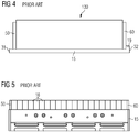
- FIGS 4 and 5 show a stator 130 according to the prior art.
- the stator 130 includes the same stator support 15 and an end plate 50 at the drive end 31.
- the stator 130 further includes another end plate 60 at the non-drive end 32.
- the second end plate 60 is axially interposed between the plurality of laminations 18 of the stator body 13 and the shoulder 19. Consequently, the stack of laminations 18 of the stator body 13 is axially shorter than the stack of the stator 13 of the present invention.
- the present invention further permits:
Landscapes
- Engineering & Computer Science (AREA)
- Power Engineering (AREA)
- Life Sciences & Earth Sciences (AREA)
- Sustainable Energy (AREA)
- Sustainable Development (AREA)
- Chemical & Material Sciences (AREA)
- Combustion & Propulsion (AREA)
- Mechanical Engineering (AREA)
- General Engineering & Computer Science (AREA)
- Iron Core Of Rotating Electric Machines (AREA)
- Wind Motors (AREA)
- Connection Of Motors, Electrical Generators, Mechanical Devices, And The Like (AREA)
Abstract
Description
- The present invention relates to an electric generator including a stator end plate.
Particularly, but not exclusively, the present invention may be efficiently applied to an electric generator of a wind turbine. - An electric generator, such as an electric generator installed in a wind turbine, typically comprises a rotor which rotates relative to a stator.
The electric generator extends axially between a drive end (DE), connected to the driving device (i.e. the rotor with blades of the wind turbine) and an axially opposite non-drive end (NDE).
The stator normally comprises a frame body longitudinally extending along a longitudinal axis and including a stator yoke and a plurality of teeth protruding according to a radial direction from the stator yoke to respective tooth radial ends. Each tooth extends also longitudinally between a first tooth longitudinal end and a second tooth longitudinal end. In the stator a plurality of slots are also defined, each slot being delimited circumferentially by two adjacent teeth and radially extending between the stator yoke and the respective tooth radial ends. Each slot houses a respective winding.
End plates are typically provided at the teeth longitudinal ends, both at the drive end and the non-drive end. The end plates mechanically support the stator lamination and in particular the teeth during manufacturing and operation. The end plates have a typical finger shape for following the shape of the stator teeth. - Such finger plates are normally laminated and made of mild steel and are characterized by eddy current losses leading to lower rated power and efficiency (in particular a lower AEP, Annual Energy Production).
Another inconvenience of the finger plates is that they are expensive to manufacture.
In order to reduce the inconvenience of eddy current losses, the finger plates may be made of stainless steel. However, the cost (material and manufacturing) of such option is significant high. Another option is to laminate the finger plate with a layer of glue between the laminations, which constitute them. Such technique however is not particularly efficient, permitting to achieve finger plates, which are not as strong as desired. Further, the gluing is excessively expensive to implement, needing a clear environments, a pressing mechanism and other devices. - Therefore, there is still a need to provide an improved design for a stator of an electric generator, which in particular permits to reduce the above described inconveniences associated to the use of the finger end plates and at the same time to provide the necessary mechanical support for the teeth of the stator.
- This need may be met by the subject matter according to the independent claim. Advantageous embodiments of the present invention are described by the dependent claims.
- According to the present invention, it is provided a stator for an electric generator. The stator comprises:
- a stator body longitudinally extending along a longitudinal axis of the stator between a drive end and an opposite non-drive end, the stator body including a stator yoke and a plurality of teeth protruding according to a radial direction orthogonal to the longitudinal axis from the stator yoke to respective tooth radial ends, each tooth extending longitudinally between the drive end and the non-drive end,
- a stator support for radially supporting the stator body, the stator support further providing an axial support to the stator body at the non-drive end,
- According to embodiments of the invention, the stator support includes a shoulder at the non-drive end for axially supporting the stator body.
- According to further embodiments of the invention, the end plate is finger-shaped, the end plate including a plate yoke adjacent to the stator yoke and a plurality of stator teeth protruding from the plate yoke according to the radial direction and respectively adjacent to the teeth of the stator body.
Either the stator body or the end plate may include a plurality of laminations stacked along the longitudinal axis of the stator. - It has been found out the reason of eddy-current losses in electric generators is the high saturation in the stator behind the end plate. The losses are proportional to the saturation. Saturation level may vary axially across the stator lamination, particularly in skewed generators, i.e. generators where the magnets on the rotor and/or the teeth on the stator are skewed. As a consequence the saturation level at one of the ends, i.e. depending on the skew direction, may be significantly different than the saturation level at the other end. It has been measured that, when two end plates are being used, respectively at the drive end at the non-drive end, the losses in one end plate, i.e. at the non-drive end, may be more than the 90% of the total losses.
- Advantageously, the present application proposes a single end plate design, where only an end plate at the low losses end, i.e. the drive end, is used to provide mechanical support and at the same time contributed with a reduced amount of eddy-current losses.
With respect to a traditional design, the end plate at the other end, i.e. non-drive end, can be removed and the laminations of the stator can be extended by the same thickness as the end plate. Advantageously, this further contributes in reducing the eddy-current losses caused by the presence of any finger plate. - The aspects defined above and further aspects of the present invention are apparent from the examples of embodiment to be described hereinafter and are explained with reference to the examples of embodiment. The invention will be described in more detail hereinafter with reference to examples of embodiment but to which the invention is not limited.
-
- Figure 1
- shows a schematic section of a wind turbine including an electric generator according to the present invention.
- Figure 2
- shows a schematic axonometric view of the electric generator of
figure 1 . - Figure 3
- shows a schematic longitudinal section of the stator of the electric generator of
figure 2 . - Figure 4
- shows a schematic longitudinal section, corresponding to the section of
Figure 3 , of a stator for an electric generator according to the prior art. - Figure 5
- shows another and more detailed longitudinal section of a stator for an electric generator according to the prior art.
- The illustrations in the drawings are schematic. It is noted that in different figures, similar or identical elements are provided with the same reference signs.
-
Figure 1 shows a wind turbine 1 according to the invention. The wind turbine 1 comprises atower 2, which is mounted on a non-depicted fundament. Anacelle 3 is arranged on top of thetower 2.
The wind turbine 1 further comprises awind rotor 5 having two, three or more blades 4 (in the perspective ofFigure 1 only two blades 4 are visible). Thewind rotor 5 is rotatable around a rotational axis Y. When not differently specified, the terms axial, radial and circumferential in the following are made with reference to the rotational axis Y.
The blades 4 extend radially with respect to the rotational axis Y.
The wind turbine 1 comprises a permanent magnetelectric generator 10.
According to other possible embodiments of the present invention (not represented in the attached figures), the present invention may be applied to any other type of permanent magnet machine with either internal orexternal rotor 12.
Thewind rotor 5 is rotationally coupled with thepermanent magnet generator 10 either directly, e.g. direct drive or by means of a rotatablemain shaft 9 and through a gear box (not shown inFigure 1 ). A schematically depicted bearingassembly 8 is provided in order to hold in place therotor 5. The rotatablemain shaft 9 extends along the rotational axis Y. The permanentmagnet electric generator 10 extends longitudinally between adrive end 31 connected to thewind rotor 5 and an oppositenon-drive end 32.
The permanentmagnet electric generator 10 includes astator 11 and arotor 12. Therotor 12 is rotatable with respect to thestator 11 about the rotational axis Y. -
Figure 2 shows a more detailed view of thestator 11 and therotor 12 of theelectrical generator 10. Therotor 12 is radially external with respect thestator 11. A plurality of permanent magnets 17 (only onepermanent magnet 17 is shown infigure 2 ) are attached on a face of therotor 12 facing thestator 11.
According to possible embodiments of the present invention, themagnets 17 on therotor 12 may be skewed with respect to the longitudinal axis Y.
Anair gap 16, which extends circumferential around the axis Y, is provided between therotor 12 and thestator 11 and in particular between thepermanent magnets 17 and thestator 11.
Therotor 12 and thepermanent magnets 17 are not a specific part of the present invention and therefore not described in further detail. The present invention can be therefore adapted to electrical generators with or without permanent magnets.
Thestator 11 comprises astator body 13 longitudinally extending along the longitudinal axis.
Thestator 11 has a conventional lamination structure including a plurality oflaminations 18 stacked along the longitudinal axis Y.
Thestator body 13 includes astator yoke 22 and a plurality ofteeth 33 protruding according to a radial direction orthogonal to the longitudinal axis Y from thestator yoke 22 to respective tooth radial ends 38, each tooth extending longitudinally between thedrive end 31 and thenon-drive end 32.
According to possible embodiments of the present invention, theteeth 33 may be skewed with respect to the longitudinal axis Y.
With reference toFigure 3 , thestator 11 further comprises astator support 15 for radially supporting thestator body 13. Thestator support 15 further provides an axial support to thestator body 13 at thenon-drive end 32.
Ashoulder 19 extending circumferentially and protruding radially from thestator support 15 is provided at thenon-drive end 32 for axially supporting the plurality oflaminations 18 of thestator body 13.
With reference toFigures 2 and 3 , thestator 10 further comprises anend plate 50 for axially supporting the plurality oflaminations 18 of thestator body 11 at thedrive end 31. In the embodiment of the attached figures, theend plate 50 is finger-shaped, theend plate 50 including aplate yoke 51 adjacent to thestator yoke 12 and a plurality ofplate teeth 52 protruding from theplate yoke 22 according to the radial direction. Eachplate tooth 52 of theend plate 50 is adjacent to arespective tooth 33 of thestator body 13, for providing an efficient support.
According to possible embodiments of the present invention, similarly to thestator body 13, theend plate 50 includes a plurality of plate laminations stacked along the longitudinal axis Y of thestator 10. - According to another embodiment of the present invention (not shown), the
stator 10 comprises an end plate for axially supporting the plurality oflaminations 18 of thestator body 11 at thenon-drive end 32, while at the drive end 31 an axial support, for example in the form of a shoulder may be used. According to the present invention, the end plate is to be used only at the longitudinal end where the losses are lower. At such end the end plate is used to provide mechanical support and at the same time contributed with a reduced amount of eddy-current losses. -
Figures 4 and 5 show astator 130 according to the prior art. Thestator 130 includes thesame stator support 15 and anend plate 50 at thedrive end 31. Thestator 130 further includes anotherend plate 60 at thenon-drive end 32. Thesecond end plate 60 is axially interposed between the plurality oflaminations 18 of thestator body 13 and theshoulder 19. Consequently, the stack oflaminations 18 of thestator body 13 is axially shorter than the stack of thestator 13 of the present invention. - As a result, in addition to significantly reducing the eddy current loss in finger plates without losing the mechanical strength of the segment, the present invention further permits:
- a better utilization of copper as the non-drive plate can replaced by stator laminations, which contribute to the torque produced by the electric generator,
- higher torque and rated power and larger AEP,
- lower manufacturing cost due to a lower number of components,
- the possibility to use the same stator support used in known implementations.
An electric generator including the above described stator may be advantageously integrated in a wind turbine.
Claims (8)
- Electric generator (10) longitudinally extending along a longitudinal axis (Y) between a drive end (31) and an opposite non-drive end (32), the electric generator (10) comprising a stator (11) having:- a stator body (13) including a stator yoke (22) and a plurality of teeth (33) protruding according to a radial direction orthogonal to the longitudinal axis (Y) from the stator yoke (22) to respective tooth radial ends (38), each tooth extending longitudinally between the drive end (31) and the non-drive end (32),- a stator support (15) for radially supporting the stator body (13), the stator support (15) further providing an axial support to the stator body (13) at the non-drive end (32),wherein the stator (10) further comprises an end plate (50) for axially supporting the stator body (11) at one of the drive end (31) or the non-drive end (32).
- Electric generator (10) as claimed in claim 1, wherein the stator support (15) includes a shoulder (19) at the non-drive end (32) for axially supporting the stator body (13).
- Electric generator (10) as claimed in claim 1 or 2, wherein the end plate (50) is finger-shaped, the end plate (50) including a plate yoke (51) adjacent to the stator yoke (12) and a plurality of plate teeth (52) protruding from the plate yoke (22) according to the radial direction and respectively adjacent to the teeth (33) of the stator body (13).
- Electric generator (10) as claimed in any of the previous claims, wherein the stator body (13) includes a plurality of laminations (18) stacked along the longitudinal axis (Y) of the stator (10).
- Electric generator (10) as claimed in any of the previous claims, wherein the end plate (50) includes a plurality of plate laminations stacked along the longitudinal axis (Y) of the stator (10).
- Electric generator (10) as claimed in any of the previous claims, the electric generator (10) further including a rotor (12) having a plurality of magnets (17), wherein the teeth (33) on the stator body (13) and/or the magnets (17) on the rotor (12) are skewed with respect to the longitudinal axis (Y).
- A wind turbine (1) including a wind rotor (5) and an electric generator (10) according any of the previous claims, the wind rotor (5) being connected to the drive end (31) of the electric generator (10).
- Stator (11) for an electric generator (10) comprising:- a stator body (13) including a stator yoke (22) and a plurality of teeth (33) protruding according to a radial direction orthogonal to the longitudinal axis (Y) from the stator yoke (22) to respective tooth radial ends (38), each tooth extending longitudinally between a first end (31) and a second opposite end (32),- a stator support (15) for radially supporting the stator body (13), the stator support (15) further providing an axial support to the stator body (13) at one of the first end (31) and the second opposite end (32),wherein the stator (10) further comprises an end plate (50) for axially supporting the stator body (11) at the other of the first end (31) and the second opposite end (32).
Priority Applications (4)
| Application Number | Priority Date | Filing Date | Title |
|---|---|---|---|
| EP18150800.3A EP3509188B1 (en) | 2018-01-09 | 2018-01-09 | Electric generator including a stator end plate |
| DK18150800.3T DK3509188T3 (en) | 2018-01-09 | 2018-01-09 | Electric generator comprising a stator end plate |
| US16/236,672 US11146139B2 (en) | 2018-01-09 | 2018-12-31 | Electric generator including a stator end plate |
| CN201910019248.5A CN110022010B (en) | 2018-01-09 | 2019-01-09 | Generator comprising stator end plates |
Applications Claiming Priority (1)
| Application Number | Priority Date | Filing Date | Title |
|---|---|---|---|
| EP18150800.3A EP3509188B1 (en) | 2018-01-09 | 2018-01-09 | Electric generator including a stator end plate |
Publications (2)
| Publication Number | Publication Date |
|---|---|
| EP3509188A1 true EP3509188A1 (en) | 2019-07-10 |
| EP3509188B1 EP3509188B1 (en) | 2021-02-24 |
Family
ID=60953714
Family Applications (1)
| Application Number | Title | Priority Date | Filing Date |
|---|---|---|---|
| EP18150800.3A Active EP3509188B1 (en) | 2018-01-09 | 2018-01-09 | Electric generator including a stator end plate |
Country Status (4)
| Country | Link |
|---|---|
| US (1) | US11146139B2 (en) |
| EP (1) | EP3509188B1 (en) |
| CN (1) | CN110022010B (en) |
| DK (1) | DK3509188T3 (en) |
Cited By (1)
| Publication number | Priority date | Publication date | Assignee | Title |
|---|---|---|---|---|
| EP4009493A1 (en) * | 2020-12-01 | 2022-06-08 | Siemens Gamesa Renewable Energy A/S | Electric generator including a stator having an end plate |
Families Citing this family (1)
| Publication number | Priority date | Publication date | Assignee | Title |
|---|---|---|---|---|
| EP4068574A1 (en) * | 2021-03-31 | 2022-10-05 | Siemens Gamesa Renewable Energy A/S | Finger plate element and stator for an electric machine, wind turbine, and method for manufacturing a finger plate element |
Citations (5)
| Publication number | Priority date | Publication date | Assignee | Title |
|---|---|---|---|---|
| US1901315A (en) * | 1929-05-27 | 1933-03-14 | Westinghouse Electric & Mfg Co | Fabricated frame |
| DE1037572B (en) * | 1955-10-21 | 1958-08-28 | Licentia Gmbh | Electric machine in which the sheet metal stacks are united with the parts that carry them with an adhesive |
| US20110266808A1 (en) * | 2010-08-30 | 2011-11-03 | General Electric Company | Segmented stator assembly |
| US20130020885A1 (en) * | 2011-07-21 | 2013-01-24 | Kun-Li Hsieh | Encapsulated Stator |
| US20150364955A1 (en) * | 2012-12-21 | 2015-12-17 | Robert Bosch Gmbh | Stator for an electric machine |
Family Cites Families (5)
| Publication number | Priority date | Publication date | Assignee | Title |
|---|---|---|---|---|
| JP4942259B2 (en) * | 2001-07-11 | 2012-05-30 | パナソニック株式会社 | Electric motor |
| EP2348612A1 (en) * | 2010-01-20 | 2011-07-27 | Siemens Aktiengesellschaft | Magnetic component part for a rotor assembly |
| US8456048B2 (en) * | 2010-09-29 | 2013-06-04 | General Electric Company | Cooling structure for a segmented stator assembly |
| GB201113694D0 (en) | 2011-08-09 | 2011-09-21 | Univ Southampton | Turbine generator |
| EP2657520B1 (en) * | 2012-04-26 | 2016-03-30 | Siemens Aktiengesellschaft | Cooling and supporting a stator segment of an electro-mechanical machine, especially for wind turbine application |
-
2018
- 2018-01-09 DK DK18150800.3T patent/DK3509188T3/en active
- 2018-01-09 EP EP18150800.3A patent/EP3509188B1/en active Active
- 2018-12-31 US US16/236,672 patent/US11146139B2/en active Active
-
2019
- 2019-01-09 CN CN201910019248.5A patent/CN110022010B/en active Active
Patent Citations (5)
| Publication number | Priority date | Publication date | Assignee | Title |
|---|---|---|---|---|
| US1901315A (en) * | 1929-05-27 | 1933-03-14 | Westinghouse Electric & Mfg Co | Fabricated frame |
| DE1037572B (en) * | 1955-10-21 | 1958-08-28 | Licentia Gmbh | Electric machine in which the sheet metal stacks are united with the parts that carry them with an adhesive |
| US20110266808A1 (en) * | 2010-08-30 | 2011-11-03 | General Electric Company | Segmented stator assembly |
| US20130020885A1 (en) * | 2011-07-21 | 2013-01-24 | Kun-Li Hsieh | Encapsulated Stator |
| US20150364955A1 (en) * | 2012-12-21 | 2015-12-17 | Robert Bosch Gmbh | Stator for an electric machine |
Cited By (1)
| Publication number | Priority date | Publication date | Assignee | Title |
|---|---|---|---|---|
| EP4009493A1 (en) * | 2020-12-01 | 2022-06-08 | Siemens Gamesa Renewable Energy A/S | Electric generator including a stator having an end plate |
Also Published As
| Publication number | Publication date |
|---|---|
| US20190214873A1 (en) | 2019-07-11 |
| CN110022010B (en) | 2021-11-09 |
| DK3509188T3 (en) | 2021-04-26 |
| US11146139B2 (en) | 2021-10-12 |
| EP3509188B1 (en) | 2021-02-24 |
| CN110022010A (en) | 2019-07-16 |
Similar Documents
| Publication | Publication Date | Title |
|---|---|---|
| US7619332B2 (en) | Permanent magnet type electric rotating machine and wind turbine electric power generation system | |
| EP3648305B1 (en) | Electrical machine with hybrid tooth design | |
| EP2333933B1 (en) | Arrangement to compensate a non-uniform air gap of an electric machine | |
| US9680341B2 (en) | Rotating electric machine including rotor core with slots having protrusions | |
| CN115398774B (en) | Stator for electric axial flux machine and electric axial flux machine | |
| EP3133716A1 (en) | Efficient motor stator made of oriented silicon steel sheets | |
| JP2010011686A (en) | Power generator and wind-power generation apparatus equipped with the same | |
| EP3667872A1 (en) | Rotary electric machine | |
| EP4102683A1 (en) | Cooling of an electric generator | |
| US11146139B2 (en) | Electric generator including a stator end plate | |
| US11705764B2 (en) | Segmented stator for a generator, in particular for a wind turbine | |
| EP2730008B1 (en) | Laminated rotor machining enhancement | |
| EP2894765A1 (en) | Stator for a wind turbine generator | |
| EP4029115B1 (en) | Electrical machine having a segmented stator or rotor | |
| EP4009493A1 (en) | Electric generator including a stator having an end plate | |
| US12355306B2 (en) | Rotor body for a permanent magnet machine | |
| EP2760111A1 (en) | Cogging torque and torque ripple reduction of an electrically excited generator by alternatively extending rotor pole shoes | |
| EP3648306A1 (en) | Electrical machine having a segmented stator or rotor | |
| CN115004510A (en) | Stator segment, stator, wind turbine and method of manufacturing a stator segment | |
| US12525860B2 (en) | Rotor for synchronous motor | |
| EP3496233A1 (en) | Electric generator having end-windings with reduced axial protrusion | |
| EP4092885A1 (en) | Cooling at the axial ends of an electric generator | |
| US20250007380A1 (en) | Rotor and magnetic wave gear device | |
| CN109149796B (en) | Generator armature and generator using same | |
| CN201038962Y (en) | A permanent magnetic wind generator |
Legal Events
| Date | Code | Title | Description |
|---|---|---|---|
| PUAI | Public reference made under article 153(3) epc to a published international application that has entered the european phase |
Free format text: ORIGINAL CODE: 0009012 |
|
| STAA | Information on the status of an ep patent application or granted ep patent |
Free format text: STATUS: THE APPLICATION HAS BEEN PUBLISHED |
|
| AK | Designated contracting states |
Kind code of ref document: A1 Designated state(s): AL AT BE BG CH CY CZ DE DK EE ES FI FR GB GR HR HU IE IS IT LI LT LU LV MC MK MT NL NO PL PT RO RS SE SI SK SM TR |
|
| AX | Request for extension of the european patent |
Extension state: BA ME |
|
| STAA | Information on the status of an ep patent application or granted ep patent |
Free format text: STATUS: REQUEST FOR EXAMINATION WAS MADE |
|
| 17P | Request for examination filed |
Effective date: 20190719 |
|
| RBV | Designated contracting states (corrected) |
Designated state(s): AL AT BE BG CH CY CZ DE DK EE ES FI FR GB GR HR HU IE IS IT LI LT LU LV MC MK MT NL NO PL PT RO RS SE SI SK SM TR |
|
| STAA | Information on the status of an ep patent application or granted ep patent |
Free format text: STATUS: EXAMINATION IS IN PROGRESS |
|
| 17Q | First examination report despatched |
Effective date: 20200306 |
|
| GRAP | Despatch of communication of intention to grant a patent |
Free format text: ORIGINAL CODE: EPIDOSNIGR1 |
|
| STAA | Information on the status of an ep patent application or granted ep patent |
Free format text: STATUS: GRANT OF PATENT IS INTENDED |
|
| INTG | Intention to grant announced |
Effective date: 20200917 |
|
| GRAS | Grant fee paid |
Free format text: ORIGINAL CODE: EPIDOSNIGR3 |
|
| GRAA | (expected) grant |
Free format text: ORIGINAL CODE: 0009210 |
|
| STAA | Information on the status of an ep patent application or granted ep patent |
Free format text: STATUS: THE PATENT HAS BEEN GRANTED |
|
| AK | Designated contracting states |
Kind code of ref document: B1 Designated state(s): AL AT BE BG CH CY CZ DE DK EE ES FI FR GB GR HR HU IE IS IT LI LT LU LV MC MK MT NL NO PL PT RO RS SE SI SK SM TR |
|
| REG | Reference to a national code |
Ref country code: CH Ref legal event code: EP |
|
| REG | Reference to a national code |
Ref country code: AT Ref legal event code: REF Ref document number: 1365720 Country of ref document: AT Kind code of ref document: T Effective date: 20210315 |
|
| REG | Reference to a national code |
Ref country code: IE Ref legal event code: FG4D |
|
| REG | Reference to a national code |
Ref country code: DE Ref legal event code: R096 Ref document number: 602018012833 Country of ref document: DE |
|
| REG | Reference to a national code |
Ref country code: DK Ref legal event code: T3 Effective date: 20210420 |
|
| REG | Reference to a national code |
Ref country code: NL Ref legal event code: FP |
|
| REG | Reference to a national code |
Ref country code: LT Ref legal event code: MG9D |
|
| PG25 | Lapsed in a contracting state [announced via postgrant information from national office to epo] |
Ref country code: HR Free format text: LAPSE BECAUSE OF FAILURE TO SUBMIT A TRANSLATION OF THE DESCRIPTION OR TO PAY THE FEE WITHIN THE PRESCRIBED TIME-LIMIT Effective date: 20210224 Ref country code: FI Free format text: LAPSE BECAUSE OF FAILURE TO SUBMIT A TRANSLATION OF THE DESCRIPTION OR TO PAY THE FEE WITHIN THE PRESCRIBED TIME-LIMIT Effective date: 20210224 Ref country code: GR Free format text: LAPSE BECAUSE OF FAILURE TO SUBMIT A TRANSLATION OF THE DESCRIPTION OR TO PAY THE FEE WITHIN THE PRESCRIBED TIME-LIMIT Effective date: 20210525 Ref country code: NO Free format text: LAPSE BECAUSE OF FAILURE TO SUBMIT A TRANSLATION OF THE DESCRIPTION OR TO PAY THE FEE WITHIN THE PRESCRIBED TIME-LIMIT Effective date: 20210524 Ref country code: PT Free format text: LAPSE BECAUSE OF FAILURE TO SUBMIT A TRANSLATION OF THE DESCRIPTION OR TO PAY THE FEE WITHIN THE PRESCRIBED TIME-LIMIT Effective date: 20210624 Ref country code: BG Free format text: LAPSE BECAUSE OF FAILURE TO SUBMIT A TRANSLATION OF THE DESCRIPTION OR TO PAY THE FEE WITHIN THE PRESCRIBED TIME-LIMIT Effective date: 20210524 Ref country code: LT Free format text: LAPSE BECAUSE OF FAILURE TO SUBMIT A TRANSLATION OF THE DESCRIPTION OR TO PAY THE FEE WITHIN THE PRESCRIBED TIME-LIMIT Effective date: 20210224 |
|
| REG | Reference to a national code |
Ref country code: AT Ref legal event code: MK05 Ref document number: 1365720 Country of ref document: AT Kind code of ref document: T Effective date: 20210224 |
|
| PG25 | Lapsed in a contracting state [announced via postgrant information from national office to epo] |
Ref country code: SE Free format text: LAPSE BECAUSE OF FAILURE TO SUBMIT A TRANSLATION OF THE DESCRIPTION OR TO PAY THE FEE WITHIN THE PRESCRIBED TIME-LIMIT Effective date: 20210224 Ref country code: LV Free format text: LAPSE BECAUSE OF FAILURE TO SUBMIT A TRANSLATION OF THE DESCRIPTION OR TO PAY THE FEE WITHIN THE PRESCRIBED TIME-LIMIT Effective date: 20210224 Ref country code: RS Free format text: LAPSE BECAUSE OF FAILURE TO SUBMIT A TRANSLATION OF THE DESCRIPTION OR TO PAY THE FEE WITHIN THE PRESCRIBED TIME-LIMIT Effective date: 20210224 Ref country code: PL Free format text: LAPSE BECAUSE OF FAILURE TO SUBMIT A TRANSLATION OF THE DESCRIPTION OR TO PAY THE FEE WITHIN THE PRESCRIBED TIME-LIMIT Effective date: 20210224 |
|
| PG25 | Lapsed in a contracting state [announced via postgrant information from national office to epo] |
Ref country code: IS Free format text: LAPSE BECAUSE OF FAILURE TO SUBMIT A TRANSLATION OF THE DESCRIPTION OR TO PAY THE FEE WITHIN THE PRESCRIBED TIME-LIMIT Effective date: 20210624 |
|
| PG25 | Lapsed in a contracting state [announced via postgrant information from national office to epo] |
Ref country code: SM Free format text: LAPSE BECAUSE OF FAILURE TO SUBMIT A TRANSLATION OF THE DESCRIPTION OR TO PAY THE FEE WITHIN THE PRESCRIBED TIME-LIMIT Effective date: 20210224 Ref country code: AT Free format text: LAPSE BECAUSE OF FAILURE TO SUBMIT A TRANSLATION OF THE DESCRIPTION OR TO PAY THE FEE WITHIN THE PRESCRIBED TIME-LIMIT Effective date: 20210224 Ref country code: CZ Free format text: LAPSE BECAUSE OF FAILURE TO SUBMIT A TRANSLATION OF THE DESCRIPTION OR TO PAY THE FEE WITHIN THE PRESCRIBED TIME-LIMIT Effective date: 20210224 Ref country code: EE Free format text: LAPSE BECAUSE OF FAILURE TO SUBMIT A TRANSLATION OF THE DESCRIPTION OR TO PAY THE FEE WITHIN THE PRESCRIBED TIME-LIMIT Effective date: 20210224 |
|
| REG | Reference to a national code |
Ref country code: DE Ref legal event code: R097 Ref document number: 602018012833 Country of ref document: DE |
|
| PG25 | Lapsed in a contracting state [announced via postgrant information from national office to epo] |
Ref country code: RO Free format text: LAPSE BECAUSE OF FAILURE TO SUBMIT A TRANSLATION OF THE DESCRIPTION OR TO PAY THE FEE WITHIN THE PRESCRIBED TIME-LIMIT Effective date: 20210224 Ref country code: SK Free format text: LAPSE BECAUSE OF FAILURE TO SUBMIT A TRANSLATION OF THE DESCRIPTION OR TO PAY THE FEE WITHIN THE PRESCRIBED TIME-LIMIT Effective date: 20210224 |
|
| PLBE | No opposition filed within time limit |
Free format text: ORIGINAL CODE: 0009261 |
|
| STAA | Information on the status of an ep patent application or granted ep patent |
Free format text: STATUS: NO OPPOSITION FILED WITHIN TIME LIMIT |
|
| PG25 | Lapsed in a contracting state [announced via postgrant information from national office to epo] |
Ref country code: AL Free format text: LAPSE BECAUSE OF FAILURE TO SUBMIT A TRANSLATION OF THE DESCRIPTION OR TO PAY THE FEE WITHIN THE PRESCRIBED TIME-LIMIT Effective date: 20210224 Ref country code: ES Free format text: LAPSE BECAUSE OF FAILURE TO SUBMIT A TRANSLATION OF THE DESCRIPTION OR TO PAY THE FEE WITHIN THE PRESCRIBED TIME-LIMIT Effective date: 20210224 |
|
| 26N | No opposition filed |
Effective date: 20211125 |
|
| PG25 | Lapsed in a contracting state [announced via postgrant information from national office to epo] |
Ref country code: SI Free format text: LAPSE BECAUSE OF FAILURE TO SUBMIT A TRANSLATION OF THE DESCRIPTION OR TO PAY THE FEE WITHIN THE PRESCRIBED TIME-LIMIT Effective date: 20210224 |
|
| PG25 | Lapsed in a contracting state [announced via postgrant information from national office to epo] |
Ref country code: IT Free format text: LAPSE BECAUSE OF FAILURE TO SUBMIT A TRANSLATION OF THE DESCRIPTION OR TO PAY THE FEE WITHIN THE PRESCRIBED TIME-LIMIT Effective date: 20210224 |
|
| PG25 | Lapsed in a contracting state [announced via postgrant information from national office to epo] |
Ref country code: IS Free format text: LAPSE BECAUSE OF FAILURE TO SUBMIT A TRANSLATION OF THE DESCRIPTION OR TO PAY THE FEE WITHIN THE PRESCRIBED TIME-LIMIT Effective date: 20210624 |
|
| REG | Reference to a national code |
Ref country code: DE Ref legal event code: R082 Ref document number: 602018012833 Country of ref document: DE Representative=s name: SAUTHOFF, KARSTEN, DIPL.-ING. UNIV., DE |
|
| PG25 | Lapsed in a contracting state [announced via postgrant information from national office to epo] |
Ref country code: MC Free format text: LAPSE BECAUSE OF FAILURE TO SUBMIT A TRANSLATION OF THE DESCRIPTION OR TO PAY THE FEE WITHIN THE PRESCRIBED TIME-LIMIT Effective date: 20210224 |
|
| REG | Reference to a national code |
Ref country code: CH Ref legal event code: PL |
|
| REG | Reference to a national code |
Ref country code: BE Ref legal event code: MM Effective date: 20220131 |
|
| PG25 | Lapsed in a contracting state [announced via postgrant information from national office to epo] |
Ref country code: LU Free format text: LAPSE BECAUSE OF NON-PAYMENT OF DUE FEES Effective date: 20220109 |
|
| PG25 | Lapsed in a contracting state [announced via postgrant information from national office to epo] |
Ref country code: BE Free format text: LAPSE BECAUSE OF NON-PAYMENT OF DUE FEES Effective date: 20220131 |
|
| PG25 | Lapsed in a contracting state [announced via postgrant information from national office to epo] |
Ref country code: LI Free format text: LAPSE BECAUSE OF NON-PAYMENT OF DUE FEES Effective date: 20220131 Ref country code: CH Free format text: LAPSE BECAUSE OF NON-PAYMENT OF DUE FEES Effective date: 20220131 |
|
| PG25 | Lapsed in a contracting state [announced via postgrant information from national office to epo] |
Ref country code: IE Free format text: LAPSE BECAUSE OF NON-PAYMENT OF DUE FEES Effective date: 20220109 |
|
| PG25 | Lapsed in a contracting state [announced via postgrant information from national office to epo] |
Ref country code: HU Free format text: LAPSE BECAUSE OF FAILURE TO SUBMIT A TRANSLATION OF THE DESCRIPTION OR TO PAY THE FEE WITHIN THE PRESCRIBED TIME-LIMIT; INVALID AB INITIO Effective date: 20180109 |
|
| PG25 | Lapsed in a contracting state [announced via postgrant information from national office to epo] |
Ref country code: MK Free format text: LAPSE BECAUSE OF FAILURE TO SUBMIT A TRANSLATION OF THE DESCRIPTION OR TO PAY THE FEE WITHIN THE PRESCRIBED TIME-LIMIT Effective date: 20210224 Ref country code: CY Free format text: LAPSE BECAUSE OF FAILURE TO SUBMIT A TRANSLATION OF THE DESCRIPTION OR TO PAY THE FEE WITHIN THE PRESCRIBED TIME-LIMIT Effective date: 20210224 |
|
| PG25 | Lapsed in a contracting state [announced via postgrant information from national office to epo] |
Ref country code: MT Free format text: LAPSE BECAUSE OF FAILURE TO SUBMIT A TRANSLATION OF THE DESCRIPTION OR TO PAY THE FEE WITHIN THE PRESCRIBED TIME-LIMIT Effective date: 20210224 |
|
| PGFP | Annual fee paid to national office [announced via postgrant information from national office to epo] |
Ref country code: NL Payment date: 20250127 Year of fee payment: 8 |
|
| PG25 | Lapsed in a contracting state [announced via postgrant information from national office to epo] |
Ref country code: TR Free format text: LAPSE BECAUSE OF FAILURE TO SUBMIT A TRANSLATION OF THE DESCRIPTION OR TO PAY THE FEE WITHIN THE PRESCRIBED TIME-LIMIT Effective date: 20210224 |
|
| PGFP | Annual fee paid to national office [announced via postgrant information from national office to epo] |
Ref country code: GB Payment date: 20260126 Year of fee payment: 9 |
|
| PGFP | Annual fee paid to national office [announced via postgrant information from national office to epo] |
Ref country code: DE Payment date: 20250731 Year of fee payment: 9 Ref country code: DK Payment date: 20260123 Year of fee payment: 9 |
|
| PGFP | Annual fee paid to national office [announced via postgrant information from national office to epo] |
Ref country code: FR Payment date: 20260126 Year of fee payment: 9 |