EP3509169B1 - A crimp tool receiving a detachable cassette for machining connector - Google Patents
A crimp tool receiving a detachable cassette for machining connector Download PDFInfo
- Publication number
- EP3509169B1 EP3509169B1 EP19154961.7A EP19154961A EP3509169B1 EP 3509169 B1 EP3509169 B1 EP 3509169B1 EP 19154961 A EP19154961 A EP 19154961A EP 3509169 B1 EP3509169 B1 EP 3509169B1
- Authority
- EP
- European Patent Office
- Prior art keywords
- head
- notch
- cassette
- machining
- opening
- Prior art date
- Legal status (The legal status is an assumption and is not a legal conclusion. Google has not performed a legal analysis and makes no representation as to the accuracy of the status listed.)
- Active
Links
Images



Classifications
-
- H—ELECTRICITY
- H01—ELECTRIC ELEMENTS
- H01R—ELECTRICALLY-CONDUCTIVE CONNECTIONS; STRUCTURAL ASSOCIATIONS OF A PLURALITY OF MUTUALLY-INSULATED ELECTRICAL CONNECTING ELEMENTS; COUPLING DEVICES; CURRENT COLLECTORS
- H01R43/00—Apparatus or processes specially adapted for manufacturing, assembling, maintaining, or repairing of line connectors or current collectors or for joining electric conductors
- H01R43/04—Apparatus or processes specially adapted for manufacturing, assembling, maintaining, or repairing of line connectors or current collectors or for joining electric conductors for forming connections by deformation, e.g. crimping tool
- H01R43/042—Hand tools for crimping
-
- H—ELECTRICITY
- H01—ELECTRIC ELEMENTS
- H01R—ELECTRICALLY-CONDUCTIVE CONNECTIONS; STRUCTURAL ASSOCIATIONS OF A PLURALITY OF MUTUALLY-INSULATED ELECTRICAL CONNECTING ELEMENTS; COUPLING DEVICES; CURRENT COLLECTORS
- H01R43/00—Apparatus or processes specially adapted for manufacturing, assembling, maintaining, or repairing of line connectors or current collectors or for joining electric conductors
- H01R43/04—Apparatus or processes specially adapted for manufacturing, assembling, maintaining, or repairing of line connectors or current collectors or for joining electric conductors for forming connections by deformation, e.g. crimping tool
- H01R43/042—Hand tools for crimping
- H01R43/0421—Hand tools for crimping combined with other functions, e.g. cutting
-
- B—PERFORMING OPERATIONS; TRANSPORTING
- B25—HAND TOOLS; PORTABLE POWER-DRIVEN TOOLS; MANIPULATORS
- B25B—TOOLS OR BENCH DEVICES NOT OTHERWISE PROVIDED FOR, FOR FASTENING, CONNECTING, DISENGAGING, OR HOLDING
- B25B27/00—Hand tools, specially adapted for fitting together or separating parts or objects whether or not involving some deformation, not otherwise provided for
- B25B27/02—Hand tools, specially adapted for fitting together or separating parts or objects whether or not involving some deformation, not otherwise provided for for connecting objects by press fit or detaching same
-
- B—PERFORMING OPERATIONS; TRANSPORTING
- B25—HAND TOOLS; PORTABLE POWER-DRIVEN TOOLS; MANIPULATORS
- B25B—TOOLS OR BENCH DEVICES NOT OTHERWISE PROVIDED FOR, FOR FASTENING, CONNECTING, DISENGAGING, OR HOLDING
- B25B27/00—Hand tools, specially adapted for fitting together or separating parts or objects whether or not involving some deformation, not otherwise provided for
- B25B27/14—Hand tools, specially adapted for fitting together or separating parts or objects whether or not involving some deformation, not otherwise provided for for assembling objects other than by press fit or detaching same
-
- B—PERFORMING OPERATIONS; TRANSPORTING
- B25—HAND TOOLS; PORTABLE POWER-DRIVEN TOOLS; MANIPULATORS
- B25B—TOOLS OR BENCH DEVICES NOT OTHERWISE PROVIDED FOR, FOR FASTENING, CONNECTING, DISENGAGING, OR HOLDING
- B25B33/00—Hand tools not covered by any other group in this subclass
-
- H—ELECTRICITY
- H01—ELECTRIC ELEMENTS
- H01R—ELECTRICALLY-CONDUCTIVE CONNECTIONS; STRUCTURAL ASSOCIATIONS OF A PLURALITY OF MUTUALLY-INSULATED ELECTRICAL CONNECTING ELEMENTS; COUPLING DEVICES; CURRENT COLLECTORS
- H01R43/00—Apparatus or processes specially adapted for manufacturing, assembling, maintaining, or repairing of line connectors or current collectors or for joining electric conductors
- H01R43/04—Apparatus or processes specially adapted for manufacturing, assembling, maintaining, or repairing of line connectors or current collectors or for joining electric conductors for forming connections by deformation, e.g. crimping tool
- H01R43/042—Hand tools for crimping
- H01R43/0425—Hand tools for crimping with mandrels actuated in axial direction to the wire
-
- H—ELECTRICITY
- H01—ELECTRIC ELEMENTS
- H01R—ELECTRICALLY-CONDUCTIVE CONNECTIONS; STRUCTURAL ASSOCIATIONS OF A PLURALITY OF MUTUALLY-INSULATED ELECTRICAL CONNECTING ELEMENTS; COUPLING DEVICES; CURRENT COLLECTORS
- H01R43/00—Apparatus or processes specially adapted for manufacturing, assembling, maintaining, or repairing of line connectors or current collectors or for joining electric conductors
- H01R43/04—Apparatus or processes specially adapted for manufacturing, assembling, maintaining, or repairing of line connectors or current collectors or for joining electric conductors for forming connections by deformation, e.g. crimping tool
- H01R43/058—Crimping mandrels
Definitions
- the present invention relates to a detachable cassette for machining a connector.
- Cables or wires are commonly used for transmitting signals between electronic devices.
- cables are used for transmitting signals from and to televisions, telephones, computers etc. These signals include: video signals, audio signals and packed data.
- Connectors are used for connecting cables with electronic devices and are usually disposed at the ends of the cables. These connectors include an RJ-45 connector, a connector standardized as the 8P8C modular connector, and an RJ-11 connector, a connector for telephone connections etc.
- the cable-crimping tool comprises a connector socket having a guiding slot, a crimping and cutting element, and an arm connected with the crimping and cutting element, located on the guiding slot, and being movable along the guiding slot.
- the crimping and cutting element can be installed into or removed from the tool from one side of the tool.
- a detachable cassette for machining a connector that can be insertable into or removable from either one of opposite sides of the tool and the configuration of the cassette render the insertion or removal convenient to a left or right hand or enabling the user to switch hands to while using the tool, which can alleviate carpel tunnel syndrome caused by repetitive actions.
- a crimp tool comprising a cassette for machining a connector
- the cassette is detachably disposed in a tool body having a head and a driving element.
- the direction of motion of the driving element defines a first axis.
- the cassette comprises: a cassette body and a machining block.
- the cassette body is detachably disposed in an opening of the head of the tool body and has a machining opening therein.
- the machining block is slidably disposed in the cassette body along the first axis and has an engagement element detachably engaged with the driving element of the tool body. Through the engagement element, the driving element drives the machining block to slide along the first axis to move toward or away from the machining opening.
- a crimp tool which comprises: a tool body and a cassette.
- the tool body comprises: a first handle, a second handle, a head and a driving element.
- the second handle is pivotally connected with the first handle.
- the head is connected with the first handle.
- the driving element is connected with and actuated by the second handle.
- the direction of motion of the driving element defines a first axis.
- the cassette comprises: a cassette body and a machining block.
- the cassette body is detachably disposed in an opening of the head of the tool body and has a machining opening therein.
- the machining block is slidably disposed in the cassette body along the first axis and has an engagement element for being detachably engaged with the driving element of the tool body. Through the engagement element, the driving element drives the machining block to slide along the first axis to move toward or away from the machining opening.
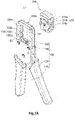
- FIG. 1A shows the crimp tool 10 of the embodiment of the present invention in a resting state wherein the handles 110, 120 thereof are in an expanded position
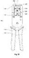
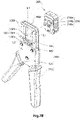
- FIG. 1B shows the crimp tool 10 in a working state wherein the handles 110, 120 of the crimp tool 10 of the embodiment of the present invention are in a contracted position
- the crimp tool 10 comprises: a tool body 100 and a cassette 200.
- the tool body 100 comprises: a first handle 110, a second handle 120, a head 130 and a driving element 140.
- the second handle 120 is pivotally connected with the first handle 110 wherein the second handle 120 pivots along a rotational path between a first position where the second handle 120 is away from the first handle 110 (as shown in FIG. 1A ) and a second position where the second handle 120 is adjacent to the first handle 110 (as shown in FIG. 1B ).
- the head 130 is connected with the first handle 110 and has an opening 131 for receiving the cassette 200.
- the driving element 140 is connected with and actuated by the second handle 120. When a user grasps the handles 110, 120, the second handle 120 urges the driving element 140 to move upward and the cassette 200 is actuated to machine the connector and the cable, such as shearing and/or crimping the connector and the cable.
- the crimp tool 10 is then switched from the resting state to the working state.
- a spring provided at the pivot of the two handles 110, 120 biases the second handle 120 so that the handles 110, 120 are urged into the expanded position, and the driving element 140 retreats to its original position.
- the crimp tool 10 is then switched from the working state to the resting state.
- the direction of motion (i.e., upward or downward direction) of the driving element 140 defines a first axis (L1).
- the cassette 200 comprises: a cassette body 210 and a machining block 220.
- the cassette body 210 is detachably disposed in an opening 131 of the head 130 of the tool body 100 and has a machining opening 214 therein.
- the cassette body 210 is provided with a slot 212 therein and the machining block 220 is slidably disposed in the slot 212 along the first axis (L1).
- the crimp tool 10 of the embodiment of the present invention can crimp connectors and cables with different specifications by using corresponding cassettes 200.
- the machining opening 214 of the cassette 200 fits with a particular connector (e.g., RJ-45 connector, RJ-11 connector or the like) and cable.
- a particular connector e.g., RJ-45 connector, RJ-11 connector or the like
- Different cassettes can be used with connectors and cables of different specifications. That is, the embodiment of the present invention provides a tool body 100 that can be used with cassettes of different machining openings.
- the cassette bodies of these cassettes are of the same or similar outer configurations such that all of them can fit with the opening 131 of the same tool body 100.
- the machining block 220 slidably provided in the slot 212 of the cassette body 210 and the engagement element 222 of the tool body 100 are interconnected.
- the machining block 220 has an engagement element 222 for being detachably engaged with the driving element 140 of the tool body 100.
- the driving element 140 drives the machining block 220 to slide along the first axis (L1) to move toward or away from the machining opening 214.
- the second handle 120 urges the driving element 140 to move upward and the driving element 140 pushes the machining block 220 to slide upward along the first axis (L1) to machine the connector and the cable via the engagement between the driving element 140 and the engagement element 222.
- the driving element 140 is a male structure, such as a T-shaped protrusion
- the engagement element 222 is a female structure, such as a groove that matches with the T-shaped protrusion.
- the T-shaped structure prevents the driving element 140 from being easily disengaged from the engagement element 222.
- the machining block 220 is actuated by the driving element 140 to slide upward or downward in a slot 212 along the first axis (L1).
- the machining opening 214 is provided in the cassette body 210 for machining a connector.
- the machining block 220 comprises: at least one machining structure 224.
- the engagement element 222 is actuated by the driving element 140 so that the machining block 220 having the engagement element 222 slides along the first axis (L1) in the slot 212 in relation to the machining opening 214.
- the at least one machining structure 224 at least partially overlaps with the machining opening 214.
- the at least one machining structure 224 machines the connector placed in the machining opening 214, such as crimping or shearing a connector having a cable for telephone connections or local area network (LAN).
- LAN local area network
- the at least one machining structure 224 comprises two machining structures, namely a crimping structure 224a disposed at one side of the cassette body 210 and a shearing structure 224b disposed at the other side of the cassette body 210.
- the crimping structure 224a is a structure for crimping a crystal joint (connector).
- the shearing structure 224b is a blade for cutting.
- the crimping structure 224a partially overlaps with one side of the machining opening 214 and the shearing structure 224b fully overlaps with the other side of the machining opening 214.
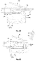
- the crimping structure 224a for crimping a crystal connector 50 comprises two crimping blocks PI, P2, which perform the crimping function simultaneously.
- the first crimping block P1 is for crimping the body of the crystal connector 50 and the second crimping block P2 is provided between the first crimping block P1 and the shearing structure 224b for securing the electrical contact blades 54 contained therein to the core(s) 62 of the cable 60.
- the crimping structure 224a When the machining block 220 is driven by the driving element 140 to the working position, the crimping structure 224a partially overlaps with one side of the machining opening 214 and the first crimping block P1 of the crimping structure 224a presses against a ridge 52 at the bottom of the crystal connector 50 so that the ridge 52 deforms and breaks. The deformed and broken ridge 52 thus squeezes the outmost insulator(s) of the cable so that the cable 60 is secured to an internal portion of the crystal connector 50. As such, a part of the crystal connector 50 holds the cable 60 and the crystal connector 50 is firmly secured to one end of the cable 60.
- the second crimping structure P2 pushes the electrical contact blades 54 of the crystal connector 50 to move upward and punches through the insulator of the cores 62 of the cable 60 to electrically connect with the cores 62 of the cable 60, so that signals can be transmitted from the cores 62 through the crystal connector 50 to a corresponding female connector.
- the shearing structure 224b is a blade for shearing off the redundant parts of the cores 62.
- the blade 224b is moved along the first axis (L1) until it fully overlaps with the side of the machining opening opposite to the crimping structure 224a and at the same time shears off the ends of the cores 62 that protrude from one end of the crystal connector 50.
- the blade 224 can also be arranged to shear off both the protruded parts of the cores 62 and the appendix 56 of crystal connector 50 as shown in FIGS.6A and 6B .
- the ends of the sheared cores 62 are flush with the sheared end of the crystal connector 50.
- the location of the shearing structure 224b relative to the crystal connector 50 can be arranged in accordance with the needs of a specific user, and might be different from that shown in FIGS. 6A and 6B .
- the cassette 200 should be firmly placed within the opening 131 of the head 130 of the tool body 100.
- the head 130 of the tool body 100 further comprises: a first connecting structure 132 disposed in the inner lateral surfaces of the opening 131 and the cassette body 210 of the cassette 200 further comprises: a second connecting structure 216 disposed thereon, wherein the first connecting structure 132 engages with the second connecting structure 216 so that the cassette body is secured within the tool body 100.
- the design of the engagements between the first connecting structure 132 and second connecting structure 216 as described below has the benefit of easy assembly of the cassette 200 to the head 130 of the tool body 100 and easy disassembly of the cassette 200 from the head 130 of the tool body 100, in addition to the benefit of the firm engagement between the cassette 220 and the opening 131 of the head 130 of the tool body 100.
- the second connecting structure 216 comprises a stopper 216a abutting against one of a first surface 130a and a second surface 130b of the head 130 of the tool body 210 along a second axis (L2) perpendicular to the first axis (L1) when the cassette body 210 is disposed in the opening 131 of the head 130 of the tool body 100.
- the second connecting structure 216 comprises: a first hook 216b and a second hook 216c respectively disposed at the two lateral sides of the cassette body 210. The first hook 216b and the second hook 216c extend away from the stopper 216 a in a direction substantially parallel to the second axis (L2).
- the stopper 216a When the stopper 216a abuts against one of the first surface 130a and the second surface 130b of the head 130 of the tool body 210, the first hook 216b and the second hook 216c engage with the other one of the first and the second surfaces 130a, 30b of the head 130 of the tool body 100 so as to secure the cassette 200 in the head 130 of the tool body 100.
- one exemplary embodiment provides a crimp tool 10 that is convenient for both right-handed and left-handed users.
- the cassette 200 can be inserted into the opening 131 of the head 130 of the body tool 100 from either the first surface 130a or the second surface 130b of the head 130 of the tool body 100.
- the second handle 120 is pivotable in relation to the first handle 110 with respect to a pivot provided at the joints of the first handle 110 and the second handle 120, the first handle 110 is defined as a stationary handle and the second handle 120 is defined as the moving handle.
- the cassette 200 When a right-handed user uses the crimp tool 10, the cassette 200 might be inserted into the opening 131 of the head 130 of the tool body 100 from the second surface 130b of the head 130 as shown in FIG. 7A .
- the right-handed user can use his/her left hand to hold a connector with cable and place it into the machining opening 214 of the cassette 200 and uses his/her right hand to operate the crimp tool 10.
- the first handle 110 is placed between and abuts against the thumb and the palm of the right hand so that the first handle 110 is held still.
- the other four fingers of the right hand are placed upon the second handle 120 for pressing against the second handle 120 to move toward the first handle 110.
- the machining block 220 When the right handle 120 is moved adjacent to (or abutting against) the first handle 110, the machining block 220 is driven by the driving element 140 to the working position and the connector with cable is machined.
- the cassette 200 when a left-handed user operates the crimp tool 10, the cassette 200 might be inserted into the opening 131 of the head 130 of the tool body 100 from the first surface 130a of the head 130 as shown in FIG. 7B . Accordingly, the left-handed user can use his/her right hand to hold a connector with cable and place it into the machining opening 214 of the cassette 200 and uses his/her left hand to operate the crimp tool 10.
- the first handle 110 is placed between and abuts against the thumb and the palm of the left hand so that the first handle 110 is held still.
- the other four fingers of the left hand are placed upon the second handle 120 for pressing against the second handle 120 to move it toward the first handle 110 so as to machine the connector.
- the first hook 216b and the second hook 216c are asymmetrically disposed at the two lateral sides of the cassette body 210 along the direction of the first axis (L1).
- the first connecting structure 132 comprises: a first notch 132a, a second notch132b, a third notch 132c and a fourth notch 132d wherein the first notch 132a and the third notch 132c are disposed in one lateral inner surface of the opening 131 of the head 130 and the second notch 132b and the fourth notch 132d are disposed in the other lateral inner surface of the opening 131 of the head 130.
- the first notch 132a and the fourth notch 132d are at the same first height and the second notch 132b and the third notch 132c are at the same second height.
- the first height is higher than the second height.
- the first notch 132a and the second notch 132b form a depression from the second surface 130b of the head 130 and the third notch 132c and the fourth notch 132d form a depression from the first surface 130a of the head 130.
- the first hook 216b and the second hook 216c respectively engage with the first notch 132a and the second notch 132b.
- the heads of the first hook 216b and the second hook 216c will ultimately abut against the first surface 130a of the head 130 and the stopper 216a abuts against the second surface 130b of the head 130.
- the cassette 200 is inserted into the opening 131 of the head 130 of the tool body 100 from the first surface 130a of the head 130 as shown in FIG.
- the first hook 216b and the second hook 216c respectively engage with the fourth notch 132d and the third notch 132c.
- the heads of the first hook 216b and the second hook 216c will ultimately abut against the second surface 130b of the head 130 and the stopper 216a abuts against the first surface 130a of the head 130.
- the cassette 200 can be placed into the opening 131 of the head from either the first surface 130a or the second surface 130b of the head 130 depending on the habits of the users. Under either of the two assembly manners, the hand tool 100 performs the same crimping and/or shearing functions well.
- the crimping tool 100 is capable of being used in one step to simultaneously secure the crystal connector 50 to the cable 60, electrically connect the electrical contact blades 54 of the crystal connector 50 to the cores 62 of the cable 60, and shear off the both the protruded parts of the cores 62 and the appendix 56 of crystal connector 50.
Landscapes
- Engineering & Computer Science (AREA)
- Manufacturing & Machinery (AREA)
- Mechanical Engineering (AREA)
- Manufacturing Of Electrical Connectors (AREA)
- Processing Of Terminals (AREA)
- Sewing Machines And Sewing (AREA)
- Connector Housings Or Holding Contact Members (AREA)
- Finish Polishing, Edge Sharpening, And Grinding By Specific Grinding Devices (AREA)
- Clamps And Clips (AREA)
- Automatic Tool Replacement In Machine Tools (AREA)
Description
- The present invention relates to a detachable cassette for machining a connector.
- Cables or wires are commonly used for transmitting signals between electronic devices. For example, cables are used for transmitting signals from and to televisions, telephones, computers etc. These signals include: video signals, audio signals and packed data. Connectors are used for connecting cables with electronic devices and are usually disposed at the ends of the cables. These connectors include an RJ-45 connector, a connector standardized as the 8P8C modular connector, and an RJ-11 connector, a connector for telephone connections etc. When the connector housing is crimped to secure the internal position of the wires, its internally contained electrical contact blades also assume the positions in which they will matingly engage the blades of corresponding contacts in the receptacle of an associated female connector. Conventional crimp tools, such as the cable-crimping tool for connectors described in
EP2166625A2 . The cable-crimping tool comprises a connector socket having a guiding slot, a crimping and cutting element, and an arm connected with the crimping and cutting element, located on the guiding slot, and being movable along the guiding slot. - However, in such conventional cable-crimping tool, the crimping and cutting element can be installed into or removed from the tool from one side of the tool.
- Given the above, there is need for a detachable cassette for machining a connector that can be insertable into or removable from either one of opposite sides of the tool and the configuration of the cassette render the insertion or removal convenient to a left or right hand or enabling the user to switch hands to while using the tool, which can alleviate carpel tunnel syndrome caused by repetitive actions..
- According to the embodiment of the invention, a crimp tool according to claim 1 comprising a cassette for machining a connector is provided. The cassette is detachably disposed in a tool body having a head and a driving element. The direction of motion of the driving element defines a first axis. The cassette comprises: a cassette body and a machining block. The cassette body is detachably disposed in an opening of the head of the tool body and has a machining opening therein. The machining block is slidably disposed in the cassette body along the first axis and has an engagement element detachably engaged with the driving element of the tool body. Through the engagement element, the driving element drives the machining block to slide along the first axis to move toward or away from the machining opening.
- In the embodiment of the invention, a crimp tool is provided, which comprises: a tool body and a cassette. The tool body comprises: a first handle, a second handle, a head and a driving element. The second handle is pivotally connected with the first handle. The head is connected with the first handle. The driving element is connected with and actuated by the second handle. The direction of motion of the driving element defines a first axis. The cassette comprises: a cassette body and a machining block. The cassette body is detachably disposed in an opening of the head of the tool body and has a machining opening therein. The machining block is slidably disposed in the cassette body along the first axis and has an engagement element for being detachably engaged with the driving element of the tool body. Through the engagement element, the driving element drives the machining block to slide along the first axis to move toward or away from the machining opening.
-
-
FIG. 1A is a schematic view showing the crimp tool of the embodiment of the present invention in a resting state; -
FIG. 1B is a schematic view showing the crimp tool of the embodiment in a working state; -
FIG. 2A is a schematic view showing the cassette of the embodiment of the present invention in a resting state wherein a shearing structure is shown; -
FIG. 2B is another schematic view showing the cassette of the embodiment in the resting state wherein the shearing structure is shown; -
FIG. 3A is a further schematic view showing the cassette of the embodiment in the resting state wherein a crimping structure is shown; -
FIG. 3B is still a further schematic view showing the cassette of the embodiment in the resting state wherein the crimping structure is shown; -
FIG. 4A is a schematic view showing the cassette of the embodiment in a working state wherein a shearing structure is shown; -
FIG. 4B is another schematic view showing the cassette of the embodiment in the working state wherein the shearing structure is shown; -
FIG. 5A is a further schematic view showing the cassette of the embodiment in the working state wherein a crimping structure is shown; -
FIG. 5A is still a further schematic view showing the cassette of the embodiment in the working state wherein the crimping structure is shown; -
FIG. 6A is a schematic view showing a connector and a cable before being sheared and crimped; -
FIG. 6B is a schematic view showing the connector and the cable after being sheared and crimped; -
FIG. 7A is a schematic view showing one exemplary embodiment in which a cassette is to be inserted into an opening of a head of a tool body from one side thereof; and -
FIG. 7B is a schematic view showing one exemplary embodiment in which a cassette is to be inserted into an opening of a head of a tool body from the other side thereof. - The characteristics, subject matter, advantages, and effects of the present invention are detailed hereinafter by reference to embodiments of the present invention and the accompanying drawings. It is understood that the drawings referred to in the following description are intended only for purposes of illustration and do not necessarily show the actual proportion and precise arrangement of the embodiments. Therefore, the proportion and arrangement shown in the drawings should not be construed as limiting or restricting the scope of the present invention defined by the appended claims.
- Please refer to
FIGS. 1A and1B .FIG. 1A shows the crimp tool 10 of the embodiment of the present invention in a resting state wherein thehandles FIG. 1B shows the crimp tool 10 in a working state wherein thehandles FIGS. 1A and1B , the crimp tool 10 comprises: atool body 100 and acassette 200. Thetool body 100 comprises: afirst handle 110, asecond handle 120, ahead 130 and a drivingelement 140. Thesecond handle 120 is pivotally connected with thefirst handle 110 wherein thesecond handle 120 pivots along a rotational path between a first position where thesecond handle 120 is away from the first handle 110 (as shown inFIG. 1A ) and a second position where thesecond handle 120 is adjacent to the first handle 110 (as shown inFIG. 1B ). Thehead 130 is connected with thefirst handle 110 and has anopening 131 for receiving thecassette 200. The drivingelement 140 is connected with and actuated by thesecond handle 120. When a user grasps thehandles second handle 120 urges the drivingelement 140 to move upward and thecassette 200 is actuated to machine the connector and the cable, such as shearing and/or crimping the connector and the cable. The crimp tool 10 is then switched from the resting state to the working state. When the user releases thehandles handles second handle 120 so that thehandles element 140 retreats to its original position. The crimp tool 10 is then switched from the working state to the resting state. During the above operation, the direction of motion (i.e., upward or downward direction) of the drivingelement 140 defines a first axis (L1). - As shown in
FIGS 2A, 2B ,3A, 3B ,7A and7B , thecassette 200 comprises: acassette body 210 and amachining block 220. Thecassette body 210 is detachably disposed in anopening 131 of thehead 130 of thetool body 100 and has amachining opening 214 therein. Thecassette body 210 is provided with aslot 212 therein and themachining block 220 is slidably disposed in theslot 212 along the first axis (L1). With this detachable design, the crimp tool 10 of the embodiment of the present invention can crimp connectors and cables with different specifications by usingcorresponding cassettes 200. Themachining opening 214 of thecassette 200 fits with a particular connector (e.g., RJ-45 connector, RJ-11 connector or the like) and cable. Different cassettes can be used with connectors and cables of different specifications. That is, the embodiment of the present invention provides atool body 100 that can be used with cassettes of different machining openings. The cassette bodies of these cassettes are of the same or similar outer configurations such that all of them can fit with theopening 131 of thesame tool body 100. - The
machining block 220 slidably provided in theslot 212 of thecassette body 210 and theengagement element 222 of thetool body 100 are interconnected. Themachining block 220 has anengagement element 222 for being detachably engaged with the drivingelement 140 of thetool body 100. Through theengagement element 222, the drivingelement 140 drives themachining block 220 to slide along the first axis (L1) to move toward or away from themachining opening 214. When thehandles second handle 120 urges the drivingelement 140 to move upward and the drivingelement 140 pushes themachining block 220 to slide upward along the first axis (L1) to machine the connector and the cable via the engagement between the drivingelement 140 and theengagement element 222. In one exemplary embodiment, the drivingelement 140 is a male structure, such as a T-shaped protrusion, and theengagement element 222 is a female structure, such as a groove that matches with the T-shaped protrusion. The T-shaped structure prevents the drivingelement 140 from being easily disengaged from theengagement element 222. As such, themachining block 220 is actuated by the drivingelement 140 to slide upward or downward in aslot 212 along the first axis (L1). - As illustrated in
FIGS. 2A-5B , themachining opening 214 is provided in thecassette body 210 for machining a connector. Corresponding to themachining opening 214, themachining block 220 comprises: at least onemachining structure 224. In operation, theengagement element 222 is actuated by the drivingelement 140 so that themachining block 220 having theengagement element 222 slides along the first axis (L1) in theslot 212 in relation to themachining opening 214. When themachining block 220 is driven to a working position, the at least onemachining structure 224 at least partially overlaps with themachining opening 214. As such, the at least onemachining structure 224 machines the connector placed in themachining opening 214, such as crimping or shearing a connector having a cable for telephone connections or local area network (LAN). - In one exemplary embodiment, the at least one
machining structure 224 comprises two machining structures, namely a crimpingstructure 224a disposed at one side of thecassette body 210 and ashearing structure 224b disposed at the other side of thecassette body 210. As shown inFigs. 3A, 3B ,5A, and 5B , the crimpingstructure 224a is a structure for crimping a crystal joint (connector). A shown inFIGS 2A, 2B ,4A and 4B , theshearing structure 224b is a blade for cutting. As illustrated inFIGS 4A, 4B ,5A and 5B , when themachining block 220 is driven to the working position, the crimpingstructure 224a partially overlaps with one side of themachining opening 214 and theshearing structure 224b fully overlaps with the other side of themachining opening 214. - In one exemplary embodiment shown in
FIGS. 6A and 6B , the crimpingstructure 224a for crimping acrystal connector 50 comprises two crimping blocks PI, P2, which perform the crimping function simultaneously. The first crimping block P1 is for crimping the body of thecrystal connector 50 and the second crimping block P2 is provided between the first crimping block P1 and theshearing structure 224b for securing theelectrical contact blades 54 contained therein to the core(s) 62 of thecable 60. When themachining block 220 is driven by the drivingelement 140 to the working position, the crimpingstructure 224a partially overlaps with one side of themachining opening 214 and the first crimping block P1 of the crimpingstructure 224a presses against aridge 52 at the bottom of thecrystal connector 50 so that theridge 52 deforms and breaks. The deformed andbroken ridge 52 thus squeezes the outmost insulator(s) of the cable so that thecable 60 is secured to an internal portion of thecrystal connector 50. As such, a part of thecrystal connector 50 holds thecable 60 and thecrystal connector 50 is firmly secured to one end of thecable 60. At the same time, the second crimping structure P2 pushes theelectrical contact blades 54 of thecrystal connector 50 to move upward and punches through the insulator of thecores 62 of thecable 60 to electrically connect with thecores 62 of thecable 60, so that signals can be transmitted from thecores 62 through thecrystal connector 50 to a corresponding female connector. - In one exemplary embodiment, the
shearing structure 224b is a blade for shearing off the redundant parts of thecores 62. When themachining block 220 is driven by the drivingelement 140 to the working position, theblade 224b is moved along the first axis (L1) until it fully overlaps with the side of the machining opening opposite to the crimpingstructure 224a and at the same time shears off the ends of thecores 62 that protrude from one end of thecrystal connector 50. In a preferred embodiment, theblade 224 can also be arranged to shear off both the protruded parts of thecores 62 and theappendix 56 ofcrystal connector 50 as shown inFIGS.6A and 6B . As such, the ends of the shearedcores 62 are flush with the sheared end of thecrystal connector 50. In alternative embodiments, the location of theshearing structure 224b relative to thecrystal connector 50 can be arranged in accordance with the needs of a specific user, and might be different from that shown inFIGS. 6A and 6B . - To ensure that the
machining block 220 works steadily and properly when it machines a connector and/or a cable, thecassette 200 should be firmly placed within theopening 131 of thehead 130 of thetool body 100. As shown inFIGS. 7A and7B , thehead 130 of thetool body 100 further comprises: a first connecting structure 132 disposed in the inner lateral surfaces of theopening 131 and thecassette body 210 of thecassette 200 further comprises: a second connectingstructure 216 disposed thereon, wherein the first connecting structure 132 engages with the second connectingstructure 216 so that the cassette body is secured within thetool body 100. The design of the engagements between the first connecting structure 132 and second connectingstructure 216 as described below has the benefit of easy assembly of thecassette 200 to thehead 130 of thetool body 100 and easy disassembly of thecassette 200 from thehead 130 of thetool body 100, in addition to the benefit of the firm engagement between thecassette 220 and theopening 131 of thehead 130 of thetool body 100. - The second connecting
structure 216 comprises astopper 216a abutting against one of afirst surface 130a and asecond surface 130b of thehead 130 of thetool body 210 along a second axis (L2) perpendicular to the first axis (L1) when thecassette body 210 is disposed in theopening 131 of thehead 130 of thetool body 100. The second connectingstructure 216 comprises: afirst hook 216b and asecond hook 216c respectively disposed at the two lateral sides of thecassette body 210. Thefirst hook 216b and thesecond hook 216c extend away from thestopper 216 a in a direction substantially parallel to the second axis (L2). When thestopper 216a abuts against one of thefirst surface 130a and thesecond surface 130b of thehead 130 of thetool body 210, thefirst hook 216b and thesecond hook 216c engage with the other one of the first and thesecond surfaces 130a, 30b of thehead 130 of thetool body 100 so as to secure thecassette 200 in thehead 130 of thetool body 100. - Referring to
FIGS. 7A and7B , one exemplary embodiment provides a crimp tool 10 that is convenient for both right-handed and left-handed users. Specifically, thecassette 200 can be inserted into theopening 131 of thehead 130 of thebody tool 100 from either thefirst surface 130a or thesecond surface 130b of thehead 130 of thetool body 100. As thesecond handle 120 is pivotable in relation to thefirst handle 110 with respect to a pivot provided at the joints of thefirst handle 110 and thesecond handle 120, thefirst handle 110 is defined as a stationary handle and thesecond handle 120 is defined as the moving handle. When a right-handed user uses the crimp tool 10, thecassette 200 might be inserted into theopening 131 of thehead 130 of thetool body 100 from thesecond surface 130b of thehead 130 as shown inFIG. 7A . As such, the right-handed user can use his/her left hand to hold a connector with cable and place it into themachining opening 214 of thecassette 200 and uses his/her right hand to operate the crimp tool 10. Thefirst handle 110 is placed between and abuts against the thumb and the palm of the right hand so that thefirst handle 110 is held still. The other four fingers of the right hand are placed upon thesecond handle 120 for pressing against thesecond handle 120 to move toward thefirst handle 110. When theright handle 120 is moved adjacent to (or abutting against) thefirst handle 110, themachining block 220 is driven by the drivingelement 140 to the working position and the connector with cable is machined. - Similarly, when a left-handed user operates the crimp tool 10, the
cassette 200 might be inserted into theopening 131 of thehead 130 of thetool body 100 from thefirst surface 130a of thehead 130 as shown inFIG. 7B . Accordingly, the left-handed user can use his/her right hand to hold a connector with cable and place it into themachining opening 214 of thecassette 200 and uses his/her left hand to operate the crimp tool 10. Thefirst handle 110 is placed between and abuts against the thumb and the palm of the left hand so that thefirst handle 110 is held still. The other four fingers of the left hand are placed upon thesecond handle 120 for pressing against thesecond handle 120 to move it toward thefirst handle 110 so as to machine the connector. - In one exemplary embodiment, the
first hook 216b and thesecond hook 216c are asymmetrically disposed at the two lateral sides of thecassette body 210 along the direction of the first axis (L1). The first connecting structure 132 comprises: afirst notch 132a, a second notch132b, a third notch 132c and afourth notch 132d wherein thefirst notch 132a and the third notch 132c are disposed in one lateral inner surface of theopening 131 of thehead 130 and the second notch 132b and thefourth notch 132d are disposed in the other lateral inner surface of theopening 131 of thehead 130. Thefirst notch 132a and thefourth notch 132d are at the same first height and the second notch 132b and the third notch 132c are at the same second height. The first height is higher than the second height. Thefirst notch 132a and the second notch 132b form a depression from thesecond surface 130b of thehead 130 and the third notch 132c and thefourth notch 132d form a depression from thefirst surface 130a of thehead 130. - With the above structures, when the
cassette 200 is inserted into theopening 131 of thehead 130 of thetool body 100 from thesecond surface 130b of thehead 130 as shown inFIG. 7A along the second axis (L2), thefirst hook 216b and thesecond hook 216c respectively engage with thefirst notch 132a and the second notch 132b. The heads of thefirst hook 216b and thesecond hook 216c will ultimately abut against thefirst surface 130a of thehead 130 and thestopper 216a abuts against thesecond surface 130b of thehead 130. Similarly, when thecassette 200 is inserted into theopening 131 of thehead 130 of thetool body 100 from thefirst surface 130a of thehead 130 as shown inFIG. 7B along the second axis (L2), thefirst hook 216b and thesecond hook 216c respectively engage with thefourth notch 132d and the third notch 132c. The heads of thefirst hook 216b and thesecond hook 216c will ultimately abut against thesecond surface 130b of thehead 130 and thestopper 216a abuts against thefirst surface 130a of thehead 130. Thus, thecassette 200 can be placed into theopening 131 of the head from either thefirst surface 130a or thesecond surface 130b of thehead 130 depending on the habits of the users. Under either of the two assembly manners, thehand tool 100 performs the same crimping and/or shearing functions well. - In addition to the benefits mentioned above, with both the crimping
structure 224a and theshearing structure 224b provided at themachining block 220, the crimpingtool 100 is capable of being used in one step to simultaneously secure thecrystal connector 50 to thecable 60, electrically connect theelectrical contact blades 54 of thecrystal connector 50 to thecores 62 of thecable 60, and shear off the both the protruded parts of thecores 62 and theappendix 56 ofcrystal connector 50.
Claims (6)
- A crimp tool comprising:
a tool body (100) comprising:a first handle (110);a second handle (120), pivotally connected with the first handle (110);a head (130), connected with the first handle (110);a driving element (140), connected with and actuated by the second handle (120), the direction of motion of the driving element (140) defining a first axis (L1); anda cassette (200) for machining a connector (50), comprising: a cassette body (210) being detachably disposed in an opening (131) of the head (130) of the tool body (100),the cassette body (210) having a machining opening (214) therein for receiving the connector (50),the machining opening (214) responsive to the driving element (140) when the cassette (200) is disposed in the tool body (100) for machining the connector (50); andcharacterized in that the cassette further comprises:a machining block (220), slidably disposed in the cassette body (210),the machining block having an engagement element (222) for being detachably engaged with the driving element (140) of the tool body (100) wherein through the engagement element, the driving element (140) drives the machining block (220) to slide along the first axis (L1) to move toward or away from the machining opening;the cassette body (210) comprising a second connecting structure (216) disposed thereon for securing the cassette body (210) within the opening (131) of the head (130) of the tool body (100); wherein the second connecting structure (216) provides releasable engagement with the first connecting structure (132) when disposed in the opening (214) (131) of the head (130) of the tool body (210) to secure the cassette body (210) within the head (130) of the tool body (210), wherein the second connecting structure (216) comprises a stopper (216a), a first hook (216b) and a second hook (216c), wherein the stopper (216a) is located to abut against one of a first surface (130a) and a second surface (130b) of the head (130) of the tool body (210) along a second axis (L2) perpendicular to the first axis (L1) when the cassette body (210) is disposed in the opening (131) of the head (130) of the tool body (210) and wherein the first hook (216b) and the second hook (216c) are respectively disposed at the two lateral sides of the cassette body (210), the first hook (216b) and the second hook (216c) extending away from the stopper (216a) in a direction substantially parallel to the second axis (L2) so as to engage with the other of the first surface (130a) and the second surface (130b) of the head (130) of the tool body (210). - The crimp tool of claim 1, wherein the first hook (216b) and the second hook (216c) are asymmetrically disposed at the two lateral sides of the cassette body (210) along the direction of the first axis (L1), and are arranged to engage with the other one of the first surface (130a) and the second surface (130b) of the head (130) of the tool body (210).
- The crimp tool of claim 2, wherein the head (130) comprises: a first notch (132a), a second notch (132b), a third notch (132c) and a fourth notch (132d) wherein the first notch (132a) and the third notch (132c) are disposed in one lateral inner surface of the opening (131) of the head (130) and the second notch (132b) and the fourth notch (132d) are disposed in the other lateral inner surface of the opening (131) of the head (130) and wherein the first notch (132a) and the second notch (132b) form a depression from the second surface (130b) of the head (130) and the third notch (132c) and the fourth notch (132d) form a depression from the first surface (130a) of the head, wherein the first notch (132a) and the fourth notch (132d) are at the same first height and the second notch (132b) and the third notch (132c) are at the same second height, the first height being higher than the second height and wherein when the cassette body (210) is inserted into the head (130) from the side of the second side surface (130b) of the head (130), the first hook (216b) and the second hook (216c) respectively engage with the first notch (132a) and the second notch (132b) and when the cassette body (210) is inserted into the head (130) from the side of the first side surface (130a) of the head (130), the first hook (216b) and the second hook (216c) respectively engage with the third notch (132c) and the fourth notch (132d).
- The crimp tool of claim 1, wherein the driving element (140) is a male structure, the engagement element (222) is a female structure, the cassette body (210) is provided with a slot (212) therein, and the machining block (220) is slidably disposed in the slot (212).
- The crimp tool of claim 4, wherein the machining block (220) comprises: a crimping structure (224a) disposed at one side of the cassette body (210) and a shearing structure (224b) disposed at the other side of the cassette body (210) and wherein when the machining block (220) is driven to a working position, the crimping structure (224a) partially overlaps with one side of the machining opening (214) and the shearing structure (224b) fully overlaps with the other side of the machining opening (214).
- The crimp tool of claim 1, wherein the second connecting structure (216) engages with the first connecting structure (132) when disposed in the opening (131) of the head (130) of the tool body (100) such that the cassette (200) is at least one of insertable into or removable from either one of opposite sides of the tool body (100).
Priority Applications (3)
| Application Number | Priority Date | Filing Date | Title |
|---|---|---|---|
| SI201631514T SI3509169T1 (en) | 2015-10-13 | 2016-02-05 | A crimp tool receiving a detachable cassette for machining connector |
| EP22161817.6A EP4037112A1 (en) | 2015-10-13 | 2016-02-05 | Cassette for machining connector |
| HRP20220499TT HRP20220499T1 (en) | 2015-10-13 | 2016-02-05 | A crimp tool receiving a detachable cassette for machining connector |
Applications Claiming Priority (2)
| Application Number | Priority Date | Filing Date | Title |
|---|---|---|---|
| TW104133572A TWI581920B (en) | 2015-10-13 | 2015-10-13 | Detachable joint processing cassette and clamp tool using the same |
| EP16154476.2A EP3157108B1 (en) | 2015-10-13 | 2016-02-05 | Detachable cassette to be disposed in a crimp tool for machining connector |
Related Parent Applications (2)
| Application Number | Title | Priority Date | Filing Date |
|---|---|---|---|
| EP16154476.2A Division EP3157108B1 (en) | 2015-10-13 | 2016-02-05 | Detachable cassette to be disposed in a crimp tool for machining connector |
| EP16154476.2A Division-Into EP3157108B1 (en) | 2015-10-13 | 2016-02-05 | Detachable cassette to be disposed in a crimp tool for machining connector |
Related Child Applications (1)
| Application Number | Title | Priority Date | Filing Date |
|---|---|---|---|
| EP22161817.6A Division EP4037112A1 (en) | 2015-10-13 | 2016-02-05 | Cassette for machining connector |
Publications (2)
| Publication Number | Publication Date |
|---|---|
| EP3509169A1 EP3509169A1 (en) | 2019-07-10 |
| EP3509169B1 true EP3509169B1 (en) | 2022-04-06 |
Family
ID=55349658
Family Applications (3)
| Application Number | Title | Priority Date | Filing Date |
|---|---|---|---|
| EP16154476.2A Active EP3157108B1 (en) | 2015-10-13 | 2016-02-05 | Detachable cassette to be disposed in a crimp tool for machining connector |
| EP22161817.6A Withdrawn EP4037112A1 (en) | 2015-10-13 | 2016-02-05 | Cassette for machining connector |
| EP19154961.7A Active EP3509169B1 (en) | 2015-10-13 | 2016-02-05 | A crimp tool receiving a detachable cassette for machining connector |
Family Applications Before (2)
| Application Number | Title | Priority Date | Filing Date |
|---|---|---|---|
| EP16154476.2A Active EP3157108B1 (en) | 2015-10-13 | 2016-02-05 | Detachable cassette to be disposed in a crimp tool for machining connector |
| EP22161817.6A Withdrawn EP4037112A1 (en) | 2015-10-13 | 2016-02-05 | Cassette for machining connector |
Country Status (12)
| Country | Link |
|---|---|
| US (2) | US10490963B2 (en) |
| EP (3) | EP3157108B1 (en) |
| JP (2) | JP6466891B2 (en) |
| KR (4) | KR101943712B1 (en) |
| CA (1) | CA2944893A1 (en) |
| DK (1) | DK3509169T3 (en) |
| ES (1) | ES2732028T3 (en) |
| HR (1) | HRP20220499T1 (en) |
| MX (1) | MX379354B (en) |
| PL (1) | PL3157108T3 (en) |
| SI (1) | SI3509169T1 (en) |
| TW (1) | TWI581920B (en) |
Families Citing this family (7)
| Publication number | Priority date | Publication date | Assignee | Title |
|---|---|---|---|---|
| TWI581920B (en) * | 2015-10-13 | 2017-05-11 | Sullstar Technologies Inc | Detachable joint processing cassette and clamp tool using the same |
| TWI614096B (en) | 2017-01-13 | 2018-02-11 | Sullstar Technologies Inc | Clamp tool and adjustable limit mechanism |
| TWI669872B (en) * | 2017-12-28 | 2019-08-21 | 加捷實業有限公司 | Crimping hand tool |
| EP3656504B1 (en) * | 2018-11-20 | 2022-02-23 | WEZAG GmbH & Co. KG | Press tool, press tool set, press tool network and method for crimping a workpiece |
| JP1639042S (en) | 2018-10-22 | 2019-08-13 | ||
| TWI708664B (en) * | 2020-01-21 | 2020-11-01 | 亨龍工業有限公司 | Press cutting tool |
| KR102239878B1 (en) * | 2020-12-29 | 2021-04-12 | 진성우 | Separated tool for connector pin |
Family Cites Families (26)
| Publication number | Priority date | Publication date | Assignee | Title |
|---|---|---|---|---|
| DE3137209C2 (en) * | 1981-09-18 | 1984-06-28 | Reiner 3570 Stadtallendorf Rommel | Wiring tool for wiring electrical, multi-pole connectors, plug strips or the like using clamp cutting technology |
| JPS63143774A (en) * | 1986-12-05 | 1988-06-16 | ヒロセ電機株式会社 | Wire jointer |
| US6017237A (en) * | 1996-08-26 | 2000-01-25 | Sullivan; Robert W. | Twisted-pair data cable with electrical connector attached |
| DE19713580C2 (en) | 1997-04-02 | 1999-12-30 | Wezag Gmbh | Crimping pliers for deforming a workpiece |
| US5992002A (en) * | 1998-01-09 | 1999-11-30 | Hung; Ying-Teh | Apparatus for the cutting, stripping and crimping of a plug onto a telco cord |
| US5941120A (en) | 1998-05-19 | 1999-08-24 | Hanlong Industrial Co., Ltd. | Pliers for compression connecting an end connector |
| US6324884B1 (en) * | 2000-06-30 | 2001-12-04 | Mastercool, Inc. | Hand-held portable crimping tool |
| DE10056900C1 (en) | 2000-11-16 | 2002-08-08 | Wezag Gmbh | Hand operated pliers for crimping, cutting, pressing or the like. |
| JP2003123934A (en) * | 2001-10-11 | 2003-04-25 | Ge Medical Systems Global Technology Co Llc | Terminal crimper tool |
| TW534510U (en) | 2001-12-31 | 2003-05-21 | Li Yao Ind Co Ltd | Pressing tool for cable connector |
| CN2549628Y (en) * | 2002-05-30 | 2003-05-07 | 简天赐 | Improved tool for pressing coaxial cable and terminal |
| US7103968B2 (en) | 2003-06-04 | 2006-09-12 | Tyco Electronics Corporation | Cable terminating apparatus |
| DE102007038626B3 (en) | 2007-08-16 | 2008-10-09 | Wezag Gmbh Werkzeugfabrik | Plier i.e. multi-functional plier, for processing electrical cable e.g. coaxial cable, has cutting unit moved in circumferential direction relative to plier, where cutting unit is formed as blade |
| US8516696B2 (en) | 2007-09-10 | 2013-08-27 | John Mezzalingua Associates, LLC | Hydraulic compression tool for installing a coaxial cable connector and method of operating thereof |
| DE102008012011B3 (en) * | 2008-03-01 | 2009-12-03 | Wezag Gmbh Werkzeugfabrik | pliers head |
| TWI353696B (en) * | 2008-09-05 | 2011-12-01 | Jen Nan Huang | Crimping tool of a connector for a singal line the |
| TWM350906U (en) | 2008-09-22 | 2009-02-11 | Dan Chief Entpr Co Ltd | Quick wire clamping tool for connectors |
| TW201110484A (en) | 2009-09-03 | 2011-03-16 | Toolmartt Entpr Co Ltd | Line pressing device for two in one communication connector |
| US9209585B2 (en) | 2010-02-18 | 2015-12-08 | Tyco Electronics Corporation | Crimping tool head |
| AU2010241275B2 (en) | 2010-11-05 | 2017-03-02 | Commscope Technologies Llc | Wire termination tool |
| DE102010061148A1 (en) | 2010-12-09 | 2012-06-14 | Wezag Gmbh Werkzeugfabrik | Pliers head for a pressing tongs |
| US8881368B2 (en) | 2011-11-17 | 2014-11-11 | Jyh Eng Technology Co., Ltd. | Punch down tool with a replaceable punch down block |
| TWM440852U (en) * | 2012-02-04 | 2012-11-11 | King Lugger Inc | Improved clamp plier tool structure |
| TWM445482U (en) * | 2012-09-04 | 2013-01-21 | min-zheng Zeng | Improved structure of C-type retaining ring pliers |
| TWM489056U (en) * | 2014-06-18 | 2014-11-01 | hong-wen Lin | Pliers with lighting function |
| TWI581920B (en) * | 2015-10-13 | 2017-05-11 | Sullstar Technologies Inc | Detachable joint processing cassette and clamp tool using the same |
-
2015
- 2015-10-13 TW TW104133572A patent/TWI581920B/en not_active IP Right Cessation
-
2016
- 2016-01-29 US US14/998,646 patent/US10490963B2/en active Active
- 2016-02-05 EP EP16154476.2A patent/EP3157108B1/en active Active
- 2016-02-05 ES ES16154476T patent/ES2732028T3/en active Active
- 2016-02-05 HR HRP20220499TT patent/HRP20220499T1/en unknown
- 2016-02-05 PL PL16154476T patent/PL3157108T3/en unknown
- 2016-02-05 DK DK19154961.7T patent/DK3509169T3/en active
- 2016-02-05 EP EP22161817.6A patent/EP4037112A1/en not_active Withdrawn
- 2016-02-05 SI SI201631514T patent/SI3509169T1/en unknown
- 2016-02-05 EP EP19154961.7A patent/EP3509169B1/en active Active
- 2016-10-07 CA CA2944893A patent/CA2944893A1/en active Pending
- 2016-10-12 MX MX2016013415A patent/MX379354B/en unknown
- 2016-10-13 KR KR1020160132743A patent/KR101943712B1/en not_active Expired - Fee Related
- 2016-10-13 JP JP2016201640A patent/JP6466891B2/en not_active Expired - Fee Related
-
2019
- 2019-01-10 JP JP2019002992A patent/JP6749430B2/en not_active Expired - Fee Related
- 2019-01-23 KR KR1020190008929A patent/KR102131609B1/en not_active Expired - Fee Related
- 2019-06-25 KR KR1020190075574A patent/KR102057417B1/en not_active Expired - Fee Related
- 2019-08-05 US US16/532,461 patent/US11394164B2/en active Active
-
2020
- 2020-07-01 KR KR1020200080725A patent/KR102242258B1/en not_active Expired - Fee Related
Also Published As
| Publication number | Publication date |
|---|---|
| DK3509169T3 (en) | 2022-05-02 |
| KR102242258B1 (en) | 2021-04-21 |
| CA2944893A1 (en) | 2017-04-13 |
| ES2732028T3 (en) | 2019-11-20 |
| MX379354B (en) | 2025-03-10 |
| HRP20220499T1 (en) | 2022-06-10 |
| KR20190077286A (en) | 2019-07-03 |
| KR102057417B1 (en) | 2019-12-18 |
| TWI581920B (en) | 2017-05-11 |
| JP2019071287A (en) | 2019-05-09 |
| US20190363501A1 (en) | 2019-11-28 |
| KR20190010706A (en) | 2019-01-30 |
| JP6466891B2 (en) | 2019-02-06 |
| JP6749430B2 (en) | 2020-09-02 |
| KR20170043469A (en) | 2017-04-21 |
| EP3157108A1 (en) | 2017-04-19 |
| US11394164B2 (en) | 2022-07-19 |
| KR101943712B1 (en) | 2019-01-29 |
| TW201713466A (en) | 2017-04-16 |
| US20170104305A1 (en) | 2017-04-13 |
| PL3157108T3 (en) | 2019-09-30 |
| KR20200085251A (en) | 2020-07-14 |
| MX2016013415A (en) | 2017-08-24 |
| JP2017135097A (en) | 2017-08-03 |
| EP4037112A1 (en) | 2022-08-03 |
| SI3509169T1 (en) | 2022-06-30 |
| US10490963B2 (en) | 2019-11-26 |
| EP3509169A1 (en) | 2019-07-10 |
| KR102131609B1 (en) | 2020-07-09 |
| EP3157108B1 (en) | 2019-04-10 |
Similar Documents
| Publication | Publication Date | Title |
|---|---|---|
| EP3157108B1 (en) | Detachable cassette to be disposed in a crimp tool for machining connector | |
| US10547153B2 (en) | Crimping hand tool | |
| JP6879651B2 (en) | Crimping tool with variable cam | |
| CN109273960B (en) | Removable joint machining cartridge and clamping tool using the same | |
| TWI626127B (en) | Detachable joint processing cassette and clamp tool using the same | |
| TWI865253B (en) | Wire stripper | |
| TWI666096B (en) | Detachable joint processing cassette and clamp tool using same | |
| HK1236682A1 (en) | Detachable cassette for machining connector and crimp tool having the same | |
| HK40003733B (en) | Detachable cassette for machining a connector and crimping tool using the same | |
| HK40003733A (en) | Detachable cassette for machining a connector and crimping tool using the same | |
| HK1236682A (en) | Detachable cassette for machining connector and crimp tool having the same |
Legal Events
| Date | Code | Title | Description |
|---|---|---|---|
| REG | Reference to a national code |
Ref country code: HR Ref legal event code: TUEP Ref document number: P20220499T Country of ref document: HR |
|
| PUAI | Public reference made under article 153(3) epc to a published international application that has entered the european phase |
Free format text: ORIGINAL CODE: 0009012 |
|
| STAA | Information on the status of an ep patent application or granted ep patent |
Free format text: STATUS: THE APPLICATION HAS BEEN PUBLISHED |
|
| AC | Divisional application: reference to earlier application |
Ref document number: 3157108 Country of ref document: EP Kind code of ref document: P |
|
| AK | Designated contracting states |
Kind code of ref document: A1 Designated state(s): AL AT BE BG CH CY CZ DE DK EE ES FI FR GB GR HR HU IE IS IT LI LT LU LV MC MK MT NL NO PL PT RO RS SE SI SK SM TR |
|
| STAA | Information on the status of an ep patent application or granted ep patent |
Free format text: STATUS: REQUEST FOR EXAMINATION WAS MADE |
|
| RAP1 | Party data changed (applicant data changed or rights of an application transferred) |
Owner name: SULLSTAR TECHNOLOGIES, INC. |
|
| 17P | Request for examination filed |
Effective date: 20200110 |
|
| RBV | Designated contracting states (corrected) |
Designated state(s): AL AT BE BG CH CY CZ DE DK EE ES FI FR GB GR HR HU IE IS IT LI LT LU LV MC MK MT NL NO PL PT RO RS SE SI SK SM TR |
|
| STAA | Information on the status of an ep patent application or granted ep patent |
Free format text: STATUS: EXAMINATION IS IN PROGRESS |
|
| 17Q | First examination report despatched |
Effective date: 20210323 |
|
| GRAP | Despatch of communication of intention to grant a patent |
Free format text: ORIGINAL CODE: EPIDOSNIGR1 |
|
| STAA | Information on the status of an ep patent application or granted ep patent |
Free format text: STATUS: GRANT OF PATENT IS INTENDED |
|
| INTG | Intention to grant announced |
Effective date: 20211021 |
|
| GRAS | Grant fee paid |
Free format text: ORIGINAL CODE: EPIDOSNIGR3 |
|
| GRAA | (expected) grant |
Free format text: ORIGINAL CODE: 0009210 |
|
| STAA | Information on the status of an ep patent application or granted ep patent |
Free format text: STATUS: THE PATENT HAS BEEN GRANTED |
|
| AC | Divisional application: reference to earlier application |
Ref document number: 3157108 Country of ref document: EP Kind code of ref document: P |
|
| AK | Designated contracting states |
Kind code of ref document: B1 Designated state(s): AL AT BE BG CH CY CZ DE DK EE ES FI FR GB GR HR HU IE IS IT LI LT LU LV MC MK MT NL NO PL PT RO RS SE SI SK SM TR |
|
| REG | Reference to a national code |
Ref country code: GB Ref legal event code: FG4D |
|
| REG | Reference to a national code |
Ref country code: CH Ref legal event code: EP |
|
| REG | Reference to a national code |
Ref country code: AT Ref legal event code: REF Ref document number: 1482272 Country of ref document: AT Kind code of ref document: T Effective date: 20220415 |
|
| REG | Reference to a national code |
Ref country code: IE Ref legal event code: FG4D |
|
| REG | Reference to a national code |
Ref country code: DE Ref legal event code: R096 Ref document number: 602016070968 Country of ref document: DE |
|
| REG | Reference to a national code |
Ref country code: DK Ref legal event code: T3 Effective date: 20220428 |
|
| REG | Reference to a national code |
Ref country code: NL Ref legal event code: FP |
|
| REG | Reference to a national code |
Ref country code: HR Ref legal event code: T1PR Ref document number: P20220499 Country of ref document: HR |
|
| REG | Reference to a national code |
Ref country code: LT Ref legal event code: MG9D |
|
| PG25 | Lapsed in a contracting state [announced via postgrant information from national office to epo] |
Ref country code: SE Free format text: LAPSE BECAUSE OF FAILURE TO SUBMIT A TRANSLATION OF THE DESCRIPTION OR TO PAY THE FEE WITHIN THE PRESCRIBED TIME-LIMIT Effective date: 20220406 Ref country code: PT Free format text: LAPSE BECAUSE OF FAILURE TO SUBMIT A TRANSLATION OF THE DESCRIPTION OR TO PAY THE FEE WITHIN THE PRESCRIBED TIME-LIMIT Effective date: 20220808 Ref country code: NO Free format text: LAPSE BECAUSE OF FAILURE TO SUBMIT A TRANSLATION OF THE DESCRIPTION OR TO PAY THE FEE WITHIN THE PRESCRIBED TIME-LIMIT Effective date: 20220706 Ref country code: LT Free format text: LAPSE BECAUSE OF FAILURE TO SUBMIT A TRANSLATION OF THE DESCRIPTION OR TO PAY THE FEE WITHIN THE PRESCRIBED TIME-LIMIT Effective date: 20220406 Ref country code: GR Free format text: LAPSE BECAUSE OF FAILURE TO SUBMIT A TRANSLATION OF THE DESCRIPTION OR TO PAY THE FEE WITHIN THE PRESCRIBED TIME-LIMIT Effective date: 20220707 Ref country code: FI Free format text: LAPSE BECAUSE OF FAILURE TO SUBMIT A TRANSLATION OF THE DESCRIPTION OR TO PAY THE FEE WITHIN THE PRESCRIBED TIME-LIMIT Effective date: 20220406 Ref country code: ES Free format text: LAPSE BECAUSE OF FAILURE TO SUBMIT A TRANSLATION OF THE DESCRIPTION OR TO PAY THE FEE WITHIN THE PRESCRIBED TIME-LIMIT Effective date: 20220406 Ref country code: BG Free format text: LAPSE BECAUSE OF FAILURE TO SUBMIT A TRANSLATION OF THE DESCRIPTION OR TO PAY THE FEE WITHIN THE PRESCRIBED TIME-LIMIT Effective date: 20220706 |
|
| PG25 | Lapsed in a contracting state [announced via postgrant information from national office to epo] |
Ref country code: RS Free format text: LAPSE BECAUSE OF FAILURE TO SUBMIT A TRANSLATION OF THE DESCRIPTION OR TO PAY THE FEE WITHIN THE PRESCRIBED TIME-LIMIT Effective date: 20220406 Ref country code: PL Free format text: LAPSE BECAUSE OF FAILURE TO SUBMIT A TRANSLATION OF THE DESCRIPTION OR TO PAY THE FEE WITHIN THE PRESCRIBED TIME-LIMIT Effective date: 20220406 Ref country code: LV Free format text: LAPSE BECAUSE OF FAILURE TO SUBMIT A TRANSLATION OF THE DESCRIPTION OR TO PAY THE FEE WITHIN THE PRESCRIBED TIME-LIMIT Effective date: 20220406 Ref country code: IS Free format text: LAPSE BECAUSE OF FAILURE TO SUBMIT A TRANSLATION OF THE DESCRIPTION OR TO PAY THE FEE WITHIN THE PRESCRIBED TIME-LIMIT Effective date: 20220806 |
|
| REG | Reference to a national code |
Ref country code: DE Ref legal event code: R097 Ref document number: 602016070968 Country of ref document: DE |
|
| PG25 | Lapsed in a contracting state [announced via postgrant information from national office to epo] |
Ref country code: SM Free format text: LAPSE BECAUSE OF FAILURE TO SUBMIT A TRANSLATION OF THE DESCRIPTION OR TO PAY THE FEE WITHIN THE PRESCRIBED TIME-LIMIT Effective date: 20220406 Ref country code: RO Free format text: LAPSE BECAUSE OF FAILURE TO SUBMIT A TRANSLATION OF THE DESCRIPTION OR TO PAY THE FEE WITHIN THE PRESCRIBED TIME-LIMIT Effective date: 20220406 Ref country code: EE Free format text: LAPSE BECAUSE OF FAILURE TO SUBMIT A TRANSLATION OF THE DESCRIPTION OR TO PAY THE FEE WITHIN THE PRESCRIBED TIME-LIMIT Effective date: 20220406 Ref country code: CZ Free format text: LAPSE BECAUSE OF FAILURE TO SUBMIT A TRANSLATION OF THE DESCRIPTION OR TO PAY THE FEE WITHIN THE PRESCRIBED TIME-LIMIT Effective date: 20220406 |
|
| PLBE | No opposition filed within time limit |
Free format text: ORIGINAL CODE: 0009261 |
|
| STAA | Information on the status of an ep patent application or granted ep patent |
Free format text: STATUS: NO OPPOSITION FILED WITHIN TIME LIMIT |
|
| REG | Reference to a national code |
Ref country code: HR Ref legal event code: ODRP Ref document number: P20220499 Country of ref document: HR Payment date: 20230109 Year of fee payment: 8 |
|
| 26N | No opposition filed |
Effective date: 20230110 |
|
| PG25 | Lapsed in a contracting state [announced via postgrant information from national office to epo] |
Ref country code: AL Free format text: LAPSE BECAUSE OF FAILURE TO SUBMIT A TRANSLATION OF THE DESCRIPTION OR TO PAY THE FEE WITHIN THE PRESCRIBED TIME-LIMIT Effective date: 20220406 |
|
| PGFP | Annual fee paid to national office [announced via postgrant information from national office to epo] |
Ref country code: FR Payment date: 20230109 Year of fee payment: 8 Ref country code: AT Payment date: 20230109 Year of fee payment: 8 |
|
| PGFP | Annual fee paid to national office [announced via postgrant information from national office to epo] |
Ref country code: SK Payment date: 20230109 Year of fee payment: 8 Ref country code: SI Payment date: 20230109 Year of fee payment: 8 Ref country code: IT Payment date: 20230111 Year of fee payment: 8 Ref country code: HR Payment date: 20230109 Year of fee payment: 8 Ref country code: GB Payment date: 20230112 Year of fee payment: 8 Ref country code: DE Payment date: 20230110 Year of fee payment: 8 Ref country code: BE Payment date: 20230106 Year of fee payment: 8 |
|
| PGFP | Annual fee paid to national office [announced via postgrant information from national office to epo] |
Ref country code: NL Payment date: 20230106 Year of fee payment: 8 |
|
| PG25 | Lapsed in a contracting state [announced via postgrant information from national office to epo] |
Ref country code: MC Free format text: LAPSE BECAUSE OF FAILURE TO SUBMIT A TRANSLATION OF THE DESCRIPTION OR TO PAY THE FEE WITHIN THE PRESCRIBED TIME-LIMIT Effective date: 20220406 |
|
| REG | Reference to a national code |
Ref country code: CH Ref legal event code: PL |
|
| PG25 | Lapsed in a contracting state [announced via postgrant information from national office to epo] |
Ref country code: LU Free format text: LAPSE BECAUSE OF NON-PAYMENT OF DUE FEES Effective date: 20230205 Ref country code: LI Free format text: LAPSE BECAUSE OF NON-PAYMENT OF DUE FEES Effective date: 20230228 Ref country code: CH Free format text: LAPSE BECAUSE OF NON-PAYMENT OF DUE FEES Effective date: 20230228 |
|
| REG | Reference to a national code |
Ref country code: IE Ref legal event code: MM4A |
|
| PG25 | Lapsed in a contracting state [announced via postgrant information from national office to epo] |
Ref country code: IE Free format text: LAPSE BECAUSE OF NON-PAYMENT OF DUE FEES Effective date: 20230205 |
|
| PGFP | Annual fee paid to national office [announced via postgrant information from national office to epo] |
Ref country code: DK Payment date: 20240226 Year of fee payment: 9 |
|
| REG | Reference to a national code |
Ref country code: HR Ref legal event code: PBON Ref document number: P20220499 Country of ref document: HR Effective date: 20240205 |
|
| REG | Reference to a national code |
Ref country code: DE Ref legal event code: R119 Ref document number: 602016070968 Country of ref document: DE |
|
| REG | Reference to a national code |
Ref country code: SK Ref legal event code: MM4A Ref document number: E 39823 Country of ref document: SK Effective date: 20240205 |
|
| REG | Reference to a national code |
Ref country code: NL Ref legal event code: MM Effective date: 20240301 |
|
| PG25 | Lapsed in a contracting state [announced via postgrant information from national office to epo] |
Ref country code: HR Free format text: LAPSE BECAUSE OF NON-PAYMENT OF DUE FEES Effective date: 20240205 |
|
| REG | Reference to a national code |
Ref country code: AT Ref legal event code: MM01 Ref document number: 1482272 Country of ref document: AT Kind code of ref document: T Effective date: 20240205 |
|
| GBPC | Gb: european patent ceased through non-payment of renewal fee |
Effective date: 20240205 |
|
| PG25 | Lapsed in a contracting state [announced via postgrant information from national office to epo] |
Ref country code: AT Free format text: LAPSE BECAUSE OF NON-PAYMENT OF DUE FEES Effective date: 20240205 |
|
| PG25 | Lapsed in a contracting state [announced via postgrant information from national office to epo] |
Ref country code: SK Free format text: LAPSE BECAUSE OF NON-PAYMENT OF DUE FEES Effective date: 20240205 Ref country code: SI Free format text: LAPSE BECAUSE OF NON-PAYMENT OF DUE FEES Effective date: 20240206 |
|
| REG | Reference to a national code |
Ref country code: SI Ref legal event code: KO00 Effective date: 20240930 |
|
| PG25 | Lapsed in a contracting state [announced via postgrant information from national office to epo] |
Ref country code: SK Free format text: LAPSE BECAUSE OF NON-PAYMENT OF DUE FEES Effective date: 20240205 Ref country code: SI Free format text: LAPSE BECAUSE OF NON-PAYMENT OF DUE FEES Effective date: 20240206 Ref country code: HR Free format text: LAPSE BECAUSE OF NON-PAYMENT OF DUE FEES Effective date: 20240205 Ref country code: AT Free format text: LAPSE BECAUSE OF NON-PAYMENT OF DUE FEES Effective date: 20240205 |
|
| PG25 | Lapsed in a contracting state [announced via postgrant information from national office to epo] |
Ref country code: BG Free format text: LAPSE BECAUSE OF FAILURE TO SUBMIT A TRANSLATION OF THE DESCRIPTION OR TO PAY THE FEE WITHIN THE PRESCRIBED TIME-LIMIT Effective date: 20220406 |
|
| PG25 | Lapsed in a contracting state [announced via postgrant information from national office to epo] |
Ref country code: NL Free format text: LAPSE BECAUSE OF NON-PAYMENT OF DUE FEES Effective date: 20240301 |
|
| PG25 | Lapsed in a contracting state [announced via postgrant information from national office to epo] |
Ref country code: NL Free format text: LAPSE BECAUSE OF NON-PAYMENT OF DUE FEES Effective date: 20240301 Ref country code: BG Free format text: LAPSE BECAUSE OF FAILURE TO SUBMIT A TRANSLATION OF THE DESCRIPTION OR TO PAY THE FEE WITHIN THE PRESCRIBED TIME-LIMIT Effective date: 20220406 |
|
| REG | Reference to a national code |
Ref country code: BE Ref legal event code: MM Effective date: 20240229 |
|
| REG | Reference to a national code |
Ref country code: AT Ref legal event code: UEP Ref document number: 1482272 Country of ref document: AT Kind code of ref document: T Effective date: 20220406 |
|
| PG25 | Lapsed in a contracting state [announced via postgrant information from national office to epo] |
Ref country code: DE Free format text: LAPSE BECAUSE OF NON-PAYMENT OF DUE FEES Effective date: 20240903 |
|
| PG25 | Lapsed in a contracting state [announced via postgrant information from national office to epo] |
Ref country code: BE Free format text: LAPSE BECAUSE OF NON-PAYMENT OF DUE FEES Effective date: 20240229 |
|
| PG25 | Lapsed in a contracting state [announced via postgrant information from national office to epo] |
Ref country code: GB Free format text: LAPSE BECAUSE OF NON-PAYMENT OF DUE FEES Effective date: 20240205 |
|
| PG25 | Lapsed in a contracting state [announced via postgrant information from national office to epo] |
Ref country code: FR Free format text: LAPSE BECAUSE OF NON-PAYMENT OF DUE FEES Effective date: 20240229 |
|
| PG25 | Lapsed in a contracting state [announced via postgrant information from national office to epo] |
Ref country code: GB Free format text: LAPSE BECAUSE OF NON-PAYMENT OF DUE FEES Effective date: 20240205 Ref country code: FR Free format text: LAPSE BECAUSE OF NON-PAYMENT OF DUE FEES Effective date: 20240229 Ref country code: DE Free format text: LAPSE BECAUSE OF NON-PAYMENT OF DUE FEES Effective date: 20240903 Ref country code: BE Free format text: LAPSE BECAUSE OF NON-PAYMENT OF DUE FEES Effective date: 20240229 |
|
| PG25 | Lapsed in a contracting state [announced via postgrant information from national office to epo] |
Ref country code: IT Free format text: LAPSE BECAUSE OF NON-PAYMENT OF DUE FEES Effective date: 20240205 |
|
| PG25 | Lapsed in a contracting state [announced via postgrant information from national office to epo] |
Ref country code: CY Free format text: LAPSE BECAUSE OF FAILURE TO SUBMIT A TRANSLATION OF THE DESCRIPTION OR TO PAY THE FEE WITHIN THE PRESCRIBED TIME-LIMIT; INVALID AB INITIO Effective date: 20160205 |
|
| PG25 | Lapsed in a contracting state [announced via postgrant information from national office to epo] |
Ref country code: HU Free format text: LAPSE BECAUSE OF FAILURE TO SUBMIT A TRANSLATION OF THE DESCRIPTION OR TO PAY THE FEE WITHIN THE PRESCRIBED TIME-LIMIT; INVALID AB INITIO Effective date: 20160205 |
|
| REG | Reference to a national code |
Ref country code: DK Ref legal event code: EBP Effective date: 20250228 |
|
| PG25 | Lapsed in a contracting state [announced via postgrant information from national office to epo] |
Ref country code: TR Free format text: LAPSE BECAUSE OF FAILURE TO SUBMIT A TRANSLATION OF THE DESCRIPTION OR TO PAY THE FEE WITHIN THE PRESCRIBED TIME-LIMIT Effective date: 20220406 |
|
| PG25 | Lapsed in a contracting state [announced via postgrant information from national office to epo] |
Ref country code: DK Free format text: LAPSE BECAUSE OF NON-PAYMENT OF DUE FEES Effective date: 20250228 |