EP3508947A1 - Rear side swappable fan array module design - Google Patents
Rear side swappable fan array module design Download PDFInfo
- Publication number
- EP3508947A1 EP3508947A1 EP18192560.3A EP18192560A EP3508947A1 EP 3508947 A1 EP3508947 A1 EP 3508947A1 EP 18192560 A EP18192560 A EP 18192560A EP 3508947 A1 EP3508947 A1 EP 3508947A1
- Authority
- EP
- European Patent Office
- Prior art keywords
- fan
- fan module
- units
- partition
- module
- Prior art date
- Legal status (The legal status is an assumption and is not a legal conclusion. Google has not performed a legal analysis and makes no representation as to the accuracy of the status listed.)
- Withdrawn
Links
Images





Classifications
-
- H—ELECTRICITY
- H05—ELECTRIC TECHNIQUES NOT OTHERWISE PROVIDED FOR
- H05K—PRINTED CIRCUITS; CASINGS OR CONSTRUCTIONAL DETAILS OF ELECTRIC APPARATUS; MANUFACTURE OF ASSEMBLAGES OF ELECTRICAL COMPONENTS
- H05K7/00—Constructional details common to different types of electric apparatus
- H05K7/20—Modifications to facilitate cooling, ventilating, or heating
- H05K7/20709—Modifications to facilitate cooling, ventilating, or heating for server racks or cabinets; for data centers, e.g. 19-inch computer racks
- H05K7/20718—Forced ventilation of a gaseous coolant
- H05K7/20736—Forced ventilation of a gaseous coolant within cabinets for removing heat from server blades
-
- F—MECHANICAL ENGINEERING; LIGHTING; HEATING; WEAPONS; BLASTING
- F04—POSITIVE - DISPLACEMENT MACHINES FOR LIQUIDS; PUMPS FOR LIQUIDS OR ELASTIC FLUIDS
- F04D—NON-POSITIVE-DISPLACEMENT PUMPS
- F04D25/00—Pumping installations or systems
- F04D25/02—Units comprising pumps and their driving means
- F04D25/06—Units comprising pumps and their driving means the pump being electrically driven
-
- F—MECHANICAL ENGINEERING; LIGHTING; HEATING; WEAPONS; BLASTING
- F04—POSITIVE - DISPLACEMENT MACHINES FOR LIQUIDS; PUMPS FOR LIQUIDS OR ELASTIC FLUIDS
- F04D—NON-POSITIVE-DISPLACEMENT PUMPS
- F04D25/00—Pumping installations or systems
- F04D25/16—Combinations of two or more pumps ; Producing two or more separate gas flows
- F04D25/166—Combinations of two or more pumps ; Producing two or more separate gas flows using fans
-
- F—MECHANICAL ENGINEERING; LIGHTING; HEATING; WEAPONS; BLASTING
- F04—POSITIVE - DISPLACEMENT MACHINES FOR LIQUIDS; PUMPS FOR LIQUIDS OR ELASTIC FLUIDS
- F04D—NON-POSITIVE-DISPLACEMENT PUMPS
- F04D29/00—Details, component parts, or accessories
- F04D29/002—Details, component parts, or accessories especially adapted for elastic fluid pumps
-
- G—PHYSICS
- G06—COMPUTING OR CALCULATING; COUNTING
- G06F—ELECTRIC DIGITAL DATA PROCESSING
- G06F1/00—Details not covered by groups G06F3/00 - G06F13/00 and G06F21/00
- G06F1/16—Constructional details or arrangements
- G06F1/18—Packaging or power distribution
- G06F1/183—Internal mounting support structures, e.g. for supporting printed circuit boards
-
- G—PHYSICS
- G06—COMPUTING OR CALCULATING; COUNTING
- G06F—ELECTRIC DIGITAL DATA PROCESSING
- G06F1/00—Details not covered by groups G06F3/00 - G06F13/00 and G06F21/00
- G06F1/16—Constructional details or arrangements
- G06F1/20—Cooling means
-
- H—ELECTRICITY
- H05—ELECTRIC TECHNIQUES NOT OTHERWISE PROVIDED FOR
- H05K—PRINTED CIRCUITS; CASINGS OR CONSTRUCTIONAL DETAILS OF ELECTRIC APPARATUS; MANUFACTURE OF ASSEMBLAGES OF ELECTRICAL COMPONENTS
- H05K7/00—Constructional details common to different types of electric apparatus
- H05K7/14—Mounting supporting structure in casing or on frame or rack
- H05K7/1485—Servers; Data center rooms, e.g. 19-inch computer racks
- H05K7/1488—Cabinets therefor, e.g. chassis or racks or mechanical interfaces between blades and support structures
- H05K7/1489—Cabinets therefor, e.g. chassis or racks or mechanical interfaces between blades and support structures characterized by the mounting of blades therein, e.g. brackets, rails, trays
-
- H—ELECTRICITY
- H05—ELECTRIC TECHNIQUES NOT OTHERWISE PROVIDED FOR
- H05K—PRINTED CIRCUITS; CASINGS OR CONSTRUCTIONAL DETAILS OF ELECTRIC APPARATUS; MANUFACTURE OF ASSEMBLAGES OF ELECTRICAL COMPONENTS
- H05K7/00—Constructional details common to different types of electric apparatus
- H05K7/14—Mounting supporting structure in casing or on frame or rack
- H05K7/1485—Servers; Data center rooms, e.g. 19-inch computer racks
- H05K7/1488—Cabinets therefor, e.g. chassis or racks or mechanical interfaces between blades and support structures
- H05K7/1492—Cabinets therefor, e.g. chassis or racks or mechanical interfaces between blades and support structures having electrical distribution arrangements, e.g. power supply or data communications
-
- H—ELECTRICITY
- H05—ELECTRIC TECHNIQUES NOT OTHERWISE PROVIDED FOR
- H05K—PRINTED CIRCUITS; CASINGS OR CONSTRUCTIONAL DETAILS OF ELECTRIC APPARATUS; MANUFACTURE OF ASSEMBLAGES OF ELECTRICAL COMPONENTS
- H05K7/00—Constructional details common to different types of electric apparatus
- H05K7/20—Modifications to facilitate cooling, ventilating, or heating
- H05K7/20009—Modifications to facilitate cooling, ventilating, or heating using a gaseous coolant in electronic enclosures
- H05K7/20136—Forced ventilation, e.g. by fans
- H05K7/20172—Fan mounting or fan specifications
Definitions
- This application generally relates to a fan system management, and more specifically to the maintenance and replacement of a fan unit, that can be configured based on system requirements.
- a fan system In a conventional rack system, one or more servers are often mounted with a fan system.
- a fan system typically includes a frame, with a fixed partition, to house individual fan units.
- traditional fan units can range in size. For example, in some conventional designs, eight 80 mm fan units can be housed in a fan system. In other conventional designs, up to three 140 mm fan units can be housed in a fan system. Consequently, conventional fan systems in rack systems typically have a fixed frame built-in to accommodate a fixed number of fan units of a particular size. This also results in a maximum cooling capacity for the fan system. Thus, to repair such a fan system, the entire frame and fixed partition must typically be removed, thereby increasing costs and difficultly for maintaining the rack system. Further, if the servers in the rack system are changed or modified such that the current fan system performance is not adequate to provide proper cooling, then the entire fan system would need to be replaced with a different fan configuration capable of cooling the new or modified server configuration.
- the present disclosure provides for a server device with a fan module that includes a removable or reconfigurable partition for different size fan units based on system requirements.
- the chassis can include a plurality of sleds and a fan module.
- the fan module includes a removable partition. The removable partition is configured to house a plurality of fan units.
- the plurality of fan units comprises fan units of a first size. In alternative embodiments of the disclosure, the plurality of fan units comprises fan units of a second size. In some embodiments of the disclosure, the removable partition is configured to house a plurality of first fan units and a plurality of second fan units, where the plurality of first fan units comprises a first size; and the plurality of second fan units comprises a second size.
- the removable partition comprises components that are interchangeable to accommodate the plurality of first fan units and the plurality of second fan units.
- the chassis of the fan unit can also include a power distribution board (PDB) configured to connect to the fan module via a fan board located on the fan module.
- the fan module can be made up of sheet metal.
- the present disclosure also provides a fan module configured with the flexibility to include different size fan units based on system requirements.
- the plurality of fan units comprises fan units of a first size.
- the plurality of fan units comprises fan units of a second size.
- the removable partition is configured to house a plurality of first fan units and a plurality of second fan units, where the plurality of first fan units comprises a first size, and the plurality of second fan units comprises a second size.
- the removable partition comprises components that are interchangeable to accommodate the plurality of first fan units and the plurality of second fan units.
- the present disclosure provides for a (or describes a) chassis that enables a fan module to have the flexibility to include different size fan units based on system requirements.
- the chassis can include a plurality of sleds and a fan module.
- the fan module includes a removable partition. The removable partition is configured to house a plurality of fan units.
- FIG. 1 illustrates a top view of an exemplary chassis apparatus 100 as known in the prior art.
- FIG. 2 illustrates a side view of the exemplary chassis apparatus of FIG. 1 .
- the chassis 100 can be inserted into a rack system (not shown herein), and configured to house a plurality of chasses such as chassis 100.
- the chassis 100 can include at least one sled 120.
- FIG. 1 provides a chassis 100 with a plurality of sleds 120.
- the sled can be configured to house a server or node (not shown), which is made up of multiple electronic components.
- the chassis 100 can also include a chassis management controller (CMC) 130.
- the CMC 130 is configured to manage the chassis 100.
- the CMC 130 is configured to manage data transmission within the chassis 100 and manage all nodes within the chassis.
- the chassis 100 can include a linking board 140 for each sled 120.
- the chassis 100 can also include a bus bar 150, which is configured to provide electrical power to each of the sleds 120.
- the chassis 100 can also include a power distribution board (PDB) 160 configured to connect all components within the chassis 100 to the bus bar 150.
- PDB power distribution board
- the linking board 140 of the sled 120 can be connected to the bus bar 150 via the PDB 160.
- the sled 120 can include a power supply unit 170 configured to power all of the components installed therein.
- the linking board 140 is fixed on the chassis 100 and connected to the PDB 160. In alternative conventional designs, cables can be implemented in lieu of the linking board 140.
- the CMC 130 is installed within the chassis 100 and connected to the PDB 150 by cable 135.
- the chassis 100 can also include a fan module 200.
- the fan module 200 includes a plurality of fan units 201n and a fan board 210. Each of the fan units 201n can be connected to the fan board 210 by cables (not shown).
- the fan board 210 is configured to connect to the bus bar 150 via the PDB 160 to power the fan module 200.
- FIGS. 1 and 2 illustrate the fan module 200, which includes eight total fan units 201n (four columns of units shown in FIG. 1 and two rows of units shown in FIG. 2 ) fixed within the fan module.
- FIG. 3 illustrates an isometric view of the fan module 200 including a fixed partition 250.
- the fan module 200 has a fixed partition 250 built-in to accommodate the fan units 201n based on size.
- FIG. 3 illustrates the fan module 200 for fan units 201n of a first size.
- fan units can have a dimension of 80 millimeters.
- the partition 250 is fixed within the fan module 200. As such, repairing the fan module 200 requires removing the entire fan module 200 and fixed partition 250. Further, if the current fan module's cooling performance is not adequate to optimize performance of the electronic components (not shown) within the chassis 100, the entire fan module 200 needs to be replaced with one that provides higher cooling performance.
- the present disclosure contemplates providing a fan module with a removable or reconfigurable partition.
- the fan module can be used with a variety of fan sizes in a variety of configurations. This is described in further detail below.
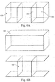
- FIGS. 4A and 4B schematically illustrates an isometric view of a fan module 400, including a removable partition 450 in accordance with an embodiment in the present disclosure.
- FIG. 4A is an assembled view and FIG. 4B is an exploded view.
- the fan module 400 can be configured to support a removable partition 450.
- spaces 460 for fans are provided.
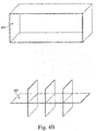
- the partition 450 is removed, the fan module 400 then has space for larger fans.
- a different partition could also be inserted to support other sizes of fans.
- the partition 450 can also be configured so that different portions of the partition 450 can be selectively removed.
- the partition 450 could support a variety of fan sizes in a variety of configurations.
- the fan module 400 and its components can be made of sheet metal using conventional metal fabrication techniques such as bending, forming, and stamping. As a result, the fan module 400 can be made very inexpensively. Alternatively, the fan module 400 and its components can be made of aluminum alloy, steel alloy, or any combination thereof. It should be realized that the fan module 400 and its components can be made of any material constructed to withstand varying temperatures and air flow of high velocity (from a plurality of fan modules not shown). The materials mentioned above are only for example, and not to limit this disclosure. A person having ordinary knowledge in the art may flexibly select any material in accordance with the disclosure.
- FIG. 5 illustrates a top isometric view of an exemplary fan module 500 configured according to the configuration shown in FIGS. 4A and 4B .
- the fan module 500 is configured to house eight fan units 501n, in accordance with an embodiment in the present disclosure(for example, an eight 80 mm fan unit).
- the fan module 500 includes a fan board 510.
- Each of the fan units 501n can be connected to the fan board 510 by cables (not shown).
- the fan board 510 can be configured to connect to a bus bar (not shown) via a PDB (not shown) to power the fan module 500.
- FIGS. 6A and 6B illustrate an isometric view of a fan module 600, including a removable partition 650 in accordance with an embodiment in the present disclosure.
- FIG. 6A is an assembled view
- FIG. 6B is an exploded view.
- the fan module 600 can be configured to support a removable partition 650.
- partition 650 can also be replaced to support various size fans.
- partition 650 could be replaced with partition 450 of FIG. 4 to support a different arrangement of fans (not shown).
- the fan module 600 and its components can be made of sheet metal using conventional metal fabrication techniques such as bending, forming, and stamping. As a result, the fan module 600 can be made very inexpensively. Alternatively, the fan module 600 and its components can be made of aluminum alloy, steel alloy, or any combination thereof. It should be realized that the fan module 600 and its components can be made of any material constructed to withstand varying temperatures and air flow of high velocity (from a plurality of fan modules not shown). The materials mentioned above are only for example, and not to limit this disclosure. A person having ordinary knowledge in the art may flexibly select any material in accordance with the disclosure.
- FIG. 7 illustrates a top isometric view of an exemplary fan module 700 configured according to the configuration in FIGS. 6A and 6B .
- the fan module 700 is configured to house three fan units 701n, in accordance with an embodiment in the present disclosure (for example, three 140 mm fan units).
- the fan module 700 also includes a fan board 710. Each of the fan units 701n can be connected to the fan board 710 by cables (not shown).
- the fan board 710 is configured to connect to a bus bar (not shown) via a PDB (not shown) to power the fan module 700.
- FIGS. 8A and 8B illustrate a top isometric view of a fan module 800 configured to house a combination of fan units of a first size and fan units of a second size, in accordance with an embodiment in the present disclosure (for example, a combination of 80 mm and 140 mm fan units).
- FIG. 8A is an assembled view
- FIG. 8B is an exploded view.
- the fan module 800 includes a removable partition 850.
- the fan module 800 can include a combination of fan units, such as fan units 501n (from FIG. 5 ) and 701n (from FIG. 7 ).
- the removable partition 850 can be customizable to accommodate system needs.
- electronic components can be positioned in different positions within a chassis, where one side can include fan units 501n (e.g., 80 mm fan units) and the opposing side can include a single fan unit 701n (e.g., a 140 mm fan unit) to optimize performance of the fan module 800.
- fan units 501n e.g. 80 mm fan units
- the opposing side can include a single fan unit 701n (e.g., a 140 mm fan unit) to optimize performance of the fan module 800.
- the partitions of FIGS. 4B and 6B can be reconfigurable based on technician preference.
- a partition can be implemented that includes the vertical and horizontal components in a variety of ways.
- the vertical and horizontal components can be arranged in any way that maximizes the number of fan units within the fan module.
- the partition components can include slits that allow for a tool-less interlocking.
- the vertical and horizontal components can be connected to each other vertically, horizontally, or even diagonally through side slits without screws or fixes.
- the partition components can include guide holes configured to receive fasteners to secure the partition components together.
- the fasteners can include, for example, screw/tapped screw hole or nut/bolt combinations. Other connections such as snap or press fits or rivets can also be used implemented.
- the partition is configured to be assembled without tools to achieve a sturdy structure of varying orientations.
Landscapes
- Engineering & Computer Science (AREA)
- General Engineering & Computer Science (AREA)
- Microelectronics & Electronic Packaging (AREA)
- Physics & Mathematics (AREA)
- Theoretical Computer Science (AREA)
- Computer Hardware Design (AREA)
- Mechanical Engineering (AREA)
- Thermal Sciences (AREA)
- Human Computer Interaction (AREA)
- General Physics & Mathematics (AREA)
- Power Engineering (AREA)
- Cooling Or The Like Of Electrical Apparatus (AREA)
- Structures Of Non-Positive Displacement Pumps (AREA)
Abstract
Description
- This application generally relates to a fan system management, and more specifically to the maintenance and replacement of a fan unit, that can be configured based on system requirements.
- In a conventional rack system, one or more servers are often mounted with a fan system. Such a fan system typically includes a frame, with a fixed partition, to house individual fan units. However, traditional fan units can range in size. For example, in some conventional designs, eight 80 mm fan units can be housed in a fan system. In other conventional designs, up to three 140 mm fan units can be housed in a fan system. Consequently, conventional fan systems in rack systems typically have a fixed frame built-in to accommodate a fixed number of fan units of a particular size. This also results in a maximum cooling capacity for the fan system. Thus, to repair such a fan system, the entire frame and fixed partition must typically be removed, thereby increasing costs and difficultly for maintaining the rack system. Further, if the servers in the rack system are changed or modified such that the current fan system performance is not adequate to provide proper cooling, then the entire fan system would need to be replaced with a different fan configuration capable of cooling the new or modified server configuration.
- The following presents a simplified summary of one or more embodiments in order to provide a basic understanding of present technology. This summary is not an extensive overview of all contemplated embodiments of the present technology, and is intended to neither identify key or critical elements of all examples, nor delineate the scope of any or all aspects of the present technology. Its sole purpose is to present some concepts of one or more examples in a simplified form as a prelude to the more detailed description that is presented later.
- The present disclosure provides for a server device with a fan module that includes a removable or reconfigurable partition for different size fan units based on system requirements. The chassis can include a plurality of sleds and a fan module. The fan module includes a removable partition. The removable partition is configured to house a plurality of fan units.
- In some embodiments of the disclosure, the plurality of fan units comprises fan units of a first size. In alternative embodiments of the disclosure, the plurality of fan units comprises fan units of a second size. In some embodiments of the disclosure, the removable partition is configured to house a plurality of first fan units and a plurality of second fan units, where the plurality of first fan units comprises a first size; and the plurality of second fan units comprises a second size. For example, the removable partition comprises components that are interchangeable to accommodate the plurality of first fan units and the plurality of second fan units. The chassis of the fan unit can also include a power distribution board (PDB) configured to connect to the fan module via a fan board located on the fan module. In some embodiments of the disclosure, the fan module can be made up of sheet metal.
- The present disclosure also provides a fan module configured with the flexibility to include different size fan units based on system requirements. In some embodiments of the disclosure, the plurality of fan units comprises fan units of a first size. In alternative embodiments of the disclosure, the plurality of fan units comprises fan units of a second size. In some embodiments of the disclosure, the removable partition is configured to house a plurality of first fan units and a plurality of second fan units, where the plurality of first fan units comprises a first size, and the plurality of second fan units comprises a second size. For example, the removable partition comprises components that are interchangeable to accommodate the plurality of first fan units and the plurality of second fan units. Further particular and preferred aspects of the present invention are set out in the accompanying independent and dependent claims. Features of the dependent claims may be combined with features of the independent claims as appropriate, and in combinations other than those explicitly set out in the claims.
- In order to describe the manner in which the above-recited and other advantages and features of the disclosure can be obtained, a more particular description of the principles described above will be rendered by reference to specific examples illustrated in the appended drawings. These drawings depict only example embodiments of the disclosure, and are therefore not to be considered as limiting of its scope. The principles are described and explained with additional specificity and detail through the use of the following drawings. The disclosure, and its advantages and drawings, will be better understood from the following description of exemplary embodiments together with reference to the accompanying drawings. These drawings depict only exemplary embodiments, and are therefore not to be considered as limitations on the scope of the various embodiments or claims.
-
FIG. 1 illustrates a top view of an exemplary chassis apparatus as known in the prior art; -
FIG. 2 illustrates a side view of the exemplary chassis apparatus ofFIG. 1 as known in the art; -
FIG. 3 illustrates an isometric view of a conventional fan module including a fixed partition; -
FIG. 4A illustrates an isometric assembled view of a fan module, including a removable partition in accordance with an embodiment in the present disclosure; -
FIG. 4B illustrates an isometric exploded view of the fan module ofFIG. 4A , including the removable partition in accordance with an embodiment in the present disclosure; -
FIG. 5 illustrates a top isometric view of anexemplary fan module 500 configured according to the configuration illustrated inFIGS. 4A and4B , in accordance with an embodiment in the present disclosure; -
FIG. 6A illustrates an isometric assembled view of a fan module, including a removable partition in accordance with an embodiment in the present disclosure; -
FIG. 6B illustrates an isometric exploded view of the fan module ofFIG. 6A , including the removable partition in accordance with an embodiment in the present disclosure; -
FIG. 7 illustrates a top isometric view of an exemplary fan module configured according to the configuration inFIGS. 6A and 6B , in accordance with an embodiment in the present disclosure; -
FIG. 8A illustrates a top isometric assembled view of a fan module configured to house a combination of fan units of a first size and fan units of a second size, in accordance with an embodiment in the present disclosure; and -
FIG. 8B illustrates a top isometric assembled view of a fan module configured to house a combination of fan units of a first size and fan units of a second size, in accordance with an embodiment in the present disclosure. - The present invention is described with reference to the attached figures, where like reference numerals are used throughout the figures to designate similar or equivalent elements. The figures are not drawn to scale, and they are provided merely to illustrate the instant invention. Several aspects of the invention are described below with reference to example applications for illustration. It should be understood that numerous specific details, relationships, and methods are set forth to provide a full understanding of the invention. One having ordinary skill in the relevant art, however, will readily recognize that the invention can be practiced without one or more of the specific details, or with other methods. In other instances, well-known structures or operations are not shown in detail to avoid obscuring the invention. The present invention is not limited by the illustrated ordering of acts or events, as some acts may occur in different orders and/or concurrently with other acts or events. Furthermore, not all illustrated acts or events are required to implement a methodology in accordance with the present invention.
- The present disclosure provides for a (or describes a) chassis that enables a fan module to have the flexibility to include different size fan units based on system requirements. The chassis can include a plurality of sleds and a fan module. The fan module includes a removable partition. The removable partition is configured to house a plurality of fan units.
-
FIG. 1 illustrates a top view of anexemplary chassis apparatus 100 as known in the prior art.FIG. 2 illustrates a side view of the exemplary chassis apparatus ofFIG. 1 . Thechassis 100 can be inserted into a rack system (not shown herein), and configured to house a plurality of chasses such aschassis 100. Thechassis 100 can include at least onesled 120.FIG. 1 provides achassis 100 with a plurality ofsleds 120. The sled can be configured to house a server or node (not shown), which is made up of multiple electronic components. Thechassis 100 can also include a chassis management controller (CMC) 130. TheCMC 130 is configured to manage thechassis 100. Specifically, theCMC 130 is configured to manage data transmission within thechassis 100 and manage all nodes within the chassis. Thechassis 100 can include a linkingboard 140 for eachsled 120. - The
chassis 100 can also include abus bar 150, which is configured to provide electrical power to each of thesleds 120. Thechassis 100 can also include a power distribution board (PDB) 160 configured to connect all components within thechassis 100 to thebus bar 150. For example, the linkingboard 140 of thesled 120 can be connected to thebus bar 150 via thePDB 160. Thesled 120 can include apower supply unit 170 configured to power all of the components installed therein. The linkingboard 140 is fixed on thechassis 100 and connected to thePDB 160. In alternative conventional designs, cables can be implemented in lieu of the linkingboard 140. TheCMC 130 is installed within thechassis 100 and connected to thePDB 150 bycable 135. - The
chassis 100 can also include afan module 200. Thefan module 200 includes a plurality offan units 201n and afan board 210. Each of thefan units 201n can be connected to thefan board 210 by cables (not shown). Thefan board 210 is configured to connect to thebus bar 150 via thePDB 160 to power thefan module 200.FIGS. 1 and 2 illustrate thefan module 200, which includes eighttotal fan units 201n (four columns of units shown inFIG. 1 and two rows of units shown inFIG. 2 ) fixed within the fan module. -
FIG. 3 illustrates an isometric view of thefan module 200 including a fixedpartition 250. Thefan module 200 has a fixedpartition 250 built-in to accommodate thefan units 201n based on size. Specifically,FIG. 3 illustrates thefan module 200 forfan units 201n of a first size. For example, fan units can have a dimension of 80 millimeters. Thepartition 250 is fixed within thefan module 200. As such, repairing thefan module 200 requires removing theentire fan module 200 and fixedpartition 250. Further, if the current fan module's cooling performance is not adequate to optimize performance of the electronic components (not shown) within thechassis 100, theentire fan module 200 needs to be replaced with one that provides higher cooling performance. - To avoid the limitations of conventional fan modules, the present disclosure contemplates providing a fan module with a removable or reconfigurable partition. Thus, by removing or reconfiguring the partition, the fan module can be used with a variety of fan sizes in a variety of configurations. This is described in further detail below.
-
FIGS. 4A and4B schematically illustrates an isometric view of afan module 400, including aremovable partition 450 in accordance with an embodiment in the present disclosure. -
FIG. 4A is an assembled view andFIG. 4B is an exploded view. As shown inFIGS. 4A and4B , thefan module 400 can be configured to support aremovable partition 450. Thus, when thepartition 450 is inserted into thefan module 400,spaces 460 for fans (not show) are provided. When thepartition 450 is removed, thefan module 400 then has space for larger fans. Alternatively, a different partition could also be inserted to support other sizes of fans. Additionally, thepartition 450 can also be configured so that different portions of thepartition 450 can be selectively removed. Thus, thepartition 450 could support a variety of fan sizes in a variety of configurations. - The present disclosure contemplates that the
fan module 400 and its components can be made of sheet metal using conventional metal fabrication techniques such as bending, forming, and stamping. As a result, thefan module 400 can be made very inexpensively. Alternatively, thefan module 400 and its components can be made of aluminum alloy, steel alloy, or any combination thereof. It should be realized that thefan module 400 and its components can be made of any material constructed to withstand varying temperatures and air flow of high velocity (from a plurality of fan modules not shown). The materials mentioned above are only for example, and not to limit this disclosure. A person having ordinary knowledge in the art may flexibly select any material in accordance with the disclosure. -
FIG. 5 illustrates a top isometric view of anexemplary fan module 500 configured according to the configuration shown inFIGS. 4A and4B . As shown inFIG. 5 , thefan module 500 is configured to house eightfan units 501n, in accordance with an embodiment in the present disclosure(for example, an eight 80 mm fan unit). As also shown inFIG. 5 , thefan module 500 includes afan board 510. Each of thefan units 501n can be connected to thefan board 510 by cables (not shown). Thefan board 510 can be configured to connect to a bus bar (not shown) via a PDB (not shown) to power thefan module 500. - As noted above, a partition for a fan module can be configured in a variety of ways to support different fan sizes and arrangements. For example,
FIGS. 6A and 6B illustrate an isometric view of afan module 600, including aremovable partition 650 in accordance with an embodiment in the present disclosure.FIG. 6A is an assembled view, andFIG. 6B is an exploded view. As shown inFIGS. 6A and 6B , thefan module 600 can be configured to support aremovable partition 650. Thus, when thepartition 650 is inserted into the module,spaces 660 for fans (not show) are provided. When thepartition 650 is removed, thefan module 600 then has space for larger fans. Alternatively,partition 650 can also be replaced to support various size fans. For example,partition 650 could be replaced withpartition 450 ofFIG. 4 to support a different arrangement of fans (not shown). - The
fan module 600 and its components can be made of sheet metal using conventional metal fabrication techniques such as bending, forming, and stamping. As a result, thefan module 600 can be made very inexpensively. Alternatively, thefan module 600 and its components can be made of aluminum alloy, steel alloy, or any combination thereof. It should be realized that thefan module 600 and its components can be made of any material constructed to withstand varying temperatures and air flow of high velocity (from a plurality of fan modules not shown). The materials mentioned above are only for example, and not to limit this disclosure. A person having ordinary knowledge in the art may flexibly select any material in accordance with the disclosure. -
FIG. 7 illustrates a top isometric view of anexemplary fan module 700 configured according to the configuration inFIGS. 6A and 6B . As shown inFIG. 7 , Thefan module 700 is configured to house threefan units 701n, in accordance with an embodiment in the present disclosure (for example, three 140 mm fan units). Thefan module 700 also includes afan board 710. Each of thefan units 701n can be connected to thefan board 710 by cables (not shown). Thefan board 710 is configured to connect to a bus bar (not shown) via a PDB (not shown) to power thefan module 700. - As noted above, a partition for a fan module in accordance with the present disclosure can be configured to support a variety of fan sizes and arrangement thereof. For example,
FIGS. 8A and 8B illustrate a top isometric view of afan module 800 configured to house a combination of fan units of a first size and fan units of a second size, in accordance with an embodiment in the present disclosure (for example, a combination of 80 mm and 140 mm fan units).FIG. 8A is an assembled view, andFIG. 8B is an exploded view. Thefan module 800 includes aremovable partition 850. In some embodiments, thefan module 800 can include a combination of fan units, such asfan units 501n (fromFIG. 5 ) and 701n (fromFIG. 7 ). Theremovable partition 850 can be customizable to accommodate system needs. For example, electronic components can be positioned in different positions within a chassis, where one side can includefan units 501n (e.g., 80 mm fan units) and the opposing side can include asingle fan unit 701n (e.g., a 140 mm fan unit) to optimize performance of thefan module 800. - The partitions of
FIGS. 4B and6B can be reconfigurable based on technician preference. A partition can be implemented that includes the vertical and horizontal components in a variety of ways. For example, the vertical and horizontal components can be arranged in any way that maximizes the number of fan units within the fan module. In some embodiments, the partition components can include slits that allow for a tool-less interlocking. For example, the vertical and horizontal components can be connected to each other vertically, horizontally, or even diagonally through side slits without screws or fixes. Furthermore, the partition components can include guide holes configured to receive fasteners to secure the partition components together. The fasteners can include, for example, screw/tapped screw hole or nut/bolt combinations. Other connections such as snap or press fits or rivets can also be used implemented. The partition is configured to be assembled without tools to achieve a sturdy structure of varying orientations. - The previous description of the disclosure is provided to enable any person skilled in the art to make or use the disclosure. Various modifications to the disclosure will be readily apparent to those skilled in the art, and the generic principles defined herein can be applied to other variations without departing from the scope of the disclosure. Thus, the disclosure is not intended to be limited to the examples and designs described herein, but is to be accorded the widest scope consistent with the principles and novel features disclosed herein. Although particular embodiments have been described herein, it will be appreciated that the invention is not limited thereto and that many modifications and additions thereto may be made within the scope of the invention. For example, various combinations of the features of the following dependent claims can be made with the features of the independent claims without departing from the scope of the present invention.
Claims (8)
- A fan module (400, 600, 800), characterized by comprising:a removable partition (450, 650, 850); anda plurality of fan units (200, 500, 700) housed within the removable partition.
- The fan module of claim 1, wherein the plurality of fan units (200, 500, 700) comprises fan units of a first size.
- The fan module of claim 1 or claim 2, wherein the plurality of fan units (200, 500, 700) comprises fan units of a second size.
- The fan module of any preceding claim, further comprising a fan board (210, 510, 710) configured to connect to a power distribution board (PDB) (160).
- The fan module of any preceding claim, wherein the fan module (400, 600, 800) comprises sheet metal.
- The fan module of any preceding claim, wherein the removable partition (850) is configured to house a plurality of first fan units and a plurality of second fan units, wherein the plurality of first fan units comprises a first size and the plurality of second fan units comprises a second size.
- The fan module of claim 6, wherein the removable partition (450, 650, 850) comprises components that are interchangeable to accommodate the plurality of first fan units and the plurality of second fan units.
- A server device comprising:a plurality of sleds (120); anda fan module (200) according to any one of claims 1-7 .
Applications Claiming Priority (2)
| Application Number | Priority Date | Filing Date | Title |
|---|---|---|---|
| US201862613869P | 2018-01-05 | 2018-01-05 | |
| US15/939,716 US10750644B2 (en) | 2018-01-05 | 2018-03-29 | Rear side swappable fan array module design |
Publications (1)
| Publication Number | Publication Date |
|---|---|
| EP3508947A1 true EP3508947A1 (en) | 2019-07-10 |
Family
ID=63491541
Family Applications (1)
| Application Number | Title | Priority Date | Filing Date |
|---|---|---|---|
| EP18192560.3A Withdrawn EP3508947A1 (en) | 2018-01-05 | 2018-09-04 | Rear side swappable fan array module design |
Country Status (5)
| Country | Link |
|---|---|
| US (1) | US10750644B2 (en) |
| EP (1) | EP3508947A1 (en) |
| JP (1) | JP2019121354A (en) |
| CN (1) | CN110007722A (en) |
| TW (1) | TWI674834B (en) |
Families Citing this family (2)
| Publication number | Priority date | Publication date | Assignee | Title |
|---|---|---|---|---|
| US11678460B2 (en) * | 2019-04-10 | 2023-06-13 | Dell Products L.P. | Fan mounting chassis |
| CN115638120A (en) | 2021-07-19 | 2023-01-24 | 纬联电子科技(中山)有限公司 | Fan bracket and electronic device containing it |
Citations (2)
| Publication number | Priority date | Publication date | Assignee | Title |
|---|---|---|---|---|
| US20090009961A1 (en) * | 2007-07-06 | 2009-01-08 | Hong Fu Jin Precision Industry(Shenzhen) Co., Ltd. | Fan holder for receiving multiple fans |
| US20150177750A1 (en) * | 2013-12-23 | 2015-06-25 | Dell, Inc. | Enhanced fan design, configuration, and control for modular, scalable and expandable, rack-based information handling system |
Family Cites Families (23)
| Publication number | Priority date | Publication date | Assignee | Title |
|---|---|---|---|---|
| US6752587B2 (en) * | 2002-08-07 | 2004-06-22 | Inventec Corporation | Modular fan assembly |
| US6839233B2 (en) * | 2003-01-02 | 2005-01-04 | Dell Products L.P. | Removable fan bay |
| US7054155B1 (en) * | 2003-03-17 | 2006-05-30 | Unisys Corporation | Fan tray assembly |
| KR100965471B1 (en) | 2004-11-02 | 2010-06-24 | 가부시키가이샤 테레비 아사히 데이터 비젼 | Subtitled still image contents creation apparatus, subtitled still image contents creation program and subtitled still image contents creation system |
| US7259962B2 (en) * | 2004-12-06 | 2007-08-21 | Chenbro Micom Co., Ltd. | Mobile fan module |
| US7312989B2 (en) * | 2004-12-06 | 2007-12-25 | Chenbro Micom Co., Ltd. | Cooler |
| TWM289019U (en) * | 2005-09-07 | 2006-03-21 | Inventec Corp | Fan stand assembling structure |
| CN100502628C (en) | 2005-10-13 | 2009-06-17 | 技嘉科技股份有限公司 | Be applied to heat dissipation mechanism and fan wall of communication product |
| TWI314186B (en) * | 2006-07-24 | 2009-09-01 | Inventec Corp | Fan device |
| CN201438798U (en) * | 2009-03-10 | 2010-04-14 | 鸿富锦精密工业(深圳)有限公司 | fan mount |
| US8400765B2 (en) * | 2010-09-20 | 2013-03-19 | Amazon Technologies, Inc. | System with air flow under data storage devices |
| US9055690B2 (en) * | 2011-03-22 | 2015-06-09 | Amazon Technologies, Inc. | Shelf-mounted modular computing unit |
| WO2013003448A2 (en) * | 2011-06-27 | 2013-01-03 | Bergquist-Torrington Company | Cooling module with parallel blowers |
| CN103149989B (en) * | 2011-12-06 | 2016-07-06 | 华北理工大学 | Fan fixer |
| US8773861B2 (en) | 2011-12-15 | 2014-07-08 | Amazon Technologies, Inc. | Reconfigurable shelf for computing modules |
| CN103841785A (en) * | 2012-11-20 | 2014-06-04 | 英业达科技有限公司 | Server cabinet |
| CN104427832B (en) * | 2013-09-06 | 2017-03-01 | 纬创资通股份有限公司 | Quick release device and electronic equipment |
| US9795050B2 (en) * | 2014-05-22 | 2017-10-17 | Super Micro Computer Inc. | Server capable of accessing and rotating storage devices accommodated therein |
| TWI548326B (en) | 2015-02-06 | 2016-09-01 | 緯創資通股份有限公司 | Fixing mechanism and electronic device with heat dissipating function |
| US10231361B2 (en) | 2015-07-30 | 2019-03-12 | Quanta Computer Inc. | Fan system management |
| US11041500B2 (en) * | 2015-09-22 | 2021-06-22 | International Business Machines Corporation | Parallel-series hybrid fan cooling apparatus and optimization |
| US20170097003A1 (en) * | 2015-10-02 | 2017-04-06 | Quanta Computer Inc. | Hybrid fan arrangement |
| KR101798732B1 (en) * | 2015-12-28 | 2017-12-12 | 엘에스산전 주식회사 | Fan assembly and electric power equipment having the same |
-
2018
- 2018-03-29 US US15/939,716 patent/US10750644B2/en active Active
- 2018-06-14 TW TW107120576A patent/TWI674834B/en active
- 2018-07-17 CN CN201810783153.6A patent/CN110007722A/en active Pending
- 2018-09-04 EP EP18192560.3A patent/EP3508947A1/en not_active Withdrawn
- 2018-10-19 JP JP2018197146A patent/JP2019121354A/en active Pending
Patent Citations (2)
| Publication number | Priority date | Publication date | Assignee | Title |
|---|---|---|---|---|
| US20090009961A1 (en) * | 2007-07-06 | 2009-01-08 | Hong Fu Jin Precision Industry(Shenzhen) Co., Ltd. | Fan holder for receiving multiple fans |
| US20150177750A1 (en) * | 2013-12-23 | 2015-06-25 | Dell, Inc. | Enhanced fan design, configuration, and control for modular, scalable and expandable, rack-based information handling system |
Also Published As
| Publication number | Publication date |
|---|---|
| CN110007722A (en) | 2019-07-12 |
| TWI674834B (en) | 2019-10-11 |
| US20190215990A1 (en) | 2019-07-11 |
| US10750644B2 (en) | 2020-08-18 |
| JP2019121354A (en) | 2019-07-22 |
| TW201931983A (en) | 2019-08-01 |
Similar Documents
| Publication | Publication Date | Title |
|---|---|---|
| US7173821B2 (en) | Computer rack with power distribution system | |
| US8441793B2 (en) | Universal rack backplane system | |
| US9113580B2 (en) | Cooled universal hardware platform | |
| US7768780B2 (en) | Flow-through cooling for computer systems | |
| US8300402B2 (en) | Server system with heat dissipation device | |
| US10225948B1 (en) | Server rack architecture that facilitates reduced current density | |
| US12222779B2 (en) | Partial-width rack-mounted computing devices | |
| US7525797B2 (en) | High density computer equipment storage system | |
| JP3565767B2 (en) | Cartridge type server unit, housing for mounting the server unit, and server device | |
| US8953326B2 (en) | Rack-mount server assembly | |
| US20100027213A1 (en) | Server | |
| US8482918B2 (en) | Server system with heat dissipating device | |
| US20080037209A1 (en) | Computer chassis for two motherboards oriented one above the other | |
| US8720043B2 (en) | Method of allocating resources in a rack system | |
| US8199485B2 (en) | Computer server system and fan module thereof | |
| US20140153181A1 (en) | Rack-mount server assembly | |
| US8441792B2 (en) | Universal conduction cooling platform | |
| US8441788B2 (en) | Server | |
| EP3509407A1 (en) | Rack pdu bracket with rotation function | |
| US20130039002A1 (en) | Server rack assembly | |
| US20130039004A1 (en) | Server rack assembly | |
| CN105404363A (en) | chassis | |
| US10750644B2 (en) | Rear side swappable fan array module design | |
| CN102478899B (en) | server | |
| CN101986239A (en) | Rack-mounted blade system |
Legal Events
| Date | Code | Title | Description |
|---|---|---|---|
| PUAI | Public reference made under article 153(3) epc to a published international application that has entered the european phase |
Free format text: ORIGINAL CODE: 0009012 |
|
| STAA | Information on the status of an ep patent application or granted ep patent |
Free format text: STATUS: THE APPLICATION HAS BEEN PUBLISHED |
|
| AK | Designated contracting states |
Kind code of ref document: A1 Designated state(s): AL AT BE BG CH CY CZ DE DK EE ES FI FR GB GR HR HU IE IS IT LI LT LU LV MC MK MT NL NO PL PT RO RS SE SI SK SM TR |
|
| AX | Request for extension of the european patent |
Extension state: BA ME |
|
| STAA | Information on the status of an ep patent application or granted ep patent |
Free format text: STATUS: REQUEST FOR EXAMINATION WAS MADE |
|
| 17P | Request for examination filed |
Effective date: 20191127 |
|
| RBV | Designated contracting states (corrected) |
Designated state(s): AL AT BE BG CH CY CZ DE DK EE ES FI FR GB GR HR HU IE IS IT LI LT LU LV MC MK MT NL NO PL PT RO RS SE SI SK SM TR |
|
| STAA | Information on the status of an ep patent application or granted ep patent |
Free format text: STATUS: EXAMINATION IS IN PROGRESS |
|
| 17Q | First examination report despatched |
Effective date: 20210128 |
|
| STAA | Information on the status of an ep patent application or granted ep patent |
Free format text: STATUS: THE APPLICATION HAS BEEN WITHDRAWN |
|
| 18W | Application withdrawn |
Effective date: 20210504 |