EP3508936A1 - Obstacle avoidance method and apparatus, movable object, and computer-readable storage medium - Google Patents
Obstacle avoidance method and apparatus, movable object, and computer-readable storage medium Download PDFInfo
- Publication number
- EP3508936A1 EP3508936A1 EP17814294.9A EP17814294A EP3508936A1 EP 3508936 A1 EP3508936 A1 EP 3508936A1 EP 17814294 A EP17814294 A EP 17814294A EP 3508936 A1 EP3508936 A1 EP 3508936A1
- Authority
- EP
- European Patent Office
- Prior art keywords
- spot
- depth value
- obstacle
- depth
- area
- Prior art date
- Legal status (The legal status is an assumption and is not a legal conclusion. Google has not performed a legal analysis and makes no representation as to the accuracy of the status listed.)
- Granted
Links
Images



Classifications
-
- G—PHYSICS
- G05—CONTROLLING; REGULATING
- G05D—SYSTEMS FOR CONTROLLING OR REGULATING NON-ELECTRIC VARIABLES
- G05D1/00—Control of position, course, altitude or attitude of land, water, air or space vehicles, e.g. using automatic pilots
- G05D1/10—Simultaneous control of position or course in three dimensions
- G05D1/101—Simultaneous control of position or course in three dimensions specially adapted for aircraft
-
- G—PHYSICS
- G08—SIGNALLING
- G08G—TRAFFIC CONTROL SYSTEMS
- G08G5/00—Traffic control systems for aircraft
- G08G5/80—Anti-collision systems
-
- G—PHYSICS
- G01—MEASURING; TESTING
- G01S—RADIO DIRECTION-FINDING; RADIO NAVIGATION; DETERMINING DISTANCE OR VELOCITY BY USE OF RADIO WAVES; LOCATING OR PRESENCE-DETECTING BY USE OF THE REFLECTION OR RERADIATION OF RADIO WAVES; ANALOGOUS ARRANGEMENTS USING OTHER WAVES
- G01S17/00—Systems using the reflection or reradiation of electromagnetic waves other than radio waves, e.g. lidar systems
- G01S17/88—Lidar systems specially adapted for specific applications
- G01S17/93—Lidar systems specially adapted for specific applications for anti-collision purposes
-
- G—PHYSICS
- G01—MEASURING; TESTING
- G01S—RADIO DIRECTION-FINDING; RADIO NAVIGATION; DETERMINING DISTANCE OR VELOCITY BY USE OF RADIO WAVES; LOCATING OR PRESENCE-DETECTING BY USE OF THE REFLECTION OR RERADIATION OF RADIO WAVES; ANALOGOUS ARRANGEMENTS USING OTHER WAVES
- G01S17/00—Systems using the reflection or reradiation of electromagnetic waves other than radio waves, e.g. lidar systems
- G01S17/88—Lidar systems specially adapted for specific applications
- G01S17/93—Lidar systems specially adapted for specific applications for anti-collision purposes
- G01S17/931—Lidar systems specially adapted for specific applications for anti-collision purposes of land vehicles
-
- G—PHYSICS
- G01—MEASURING; TESTING
- G01S—RADIO DIRECTION-FINDING; RADIO NAVIGATION; DETERMINING DISTANCE OR VELOCITY BY USE OF RADIO WAVES; LOCATING OR PRESENCE-DETECTING BY USE OF THE REFLECTION OR RERADIATION OF RADIO WAVES; ANALOGOUS ARRANGEMENTS USING OTHER WAVES
- G01S17/00—Systems using the reflection or reradiation of electromagnetic waves other than radio waves, e.g. lidar systems
- G01S17/88—Lidar systems specially adapted for specific applications
- G01S17/93—Lidar systems specially adapted for specific applications for anti-collision purposes
- G01S17/933—Lidar systems specially adapted for specific applications for anti-collision purposes of aircraft or spacecraft
-
- G—PHYSICS
- G05—CONTROLLING; REGULATING
- G05D—SYSTEMS FOR CONTROLLING OR REGULATING NON-ELECTRIC VARIABLES
- G05D1/00—Control of position, course, altitude or attitude of land, water, air or space vehicles, e.g. using automatic pilots
- G05D1/02—Control of position or course in two dimensions
- G05D1/021—Control of position or course in two dimensions specially adapted to land vehicles
- G05D1/0231—Control of position or course in two dimensions specially adapted to land vehicles using optical position detecting means
- G05D1/0238—Control of position or course in two dimensions specially adapted to land vehicles using optical position detecting means using obstacle or wall sensors
- G05D1/024—Control of position or course in two dimensions specially adapted to land vehicles using optical position detecting means using obstacle or wall sensors in combination with a laser
-
- G—PHYSICS
- G05—CONTROLLING; REGULATING
- G05D—SYSTEMS FOR CONTROLLING OR REGULATING NON-ELECTRIC VARIABLES
- G05D1/00—Control of position, course, altitude or attitude of land, water, air or space vehicles, e.g. using automatic pilots
- G05D1/10—Simultaneous control of position or course in three dimensions
- G05D1/101—Simultaneous control of position or course in three dimensions specially adapted for aircraft
- G05D1/106—Change initiated in response to external conditions, e.g. avoidance of elevated terrain or of no-fly zones
-
- G—PHYSICS
- G06—COMPUTING OR CALCULATING; COUNTING
- G06T—IMAGE DATA PROCESSING OR GENERATION, IN GENERAL
- G06T7/00—Image analysis
- G06T7/10—Segmentation; Edge detection
- G06T7/13—Edge detection
-
- G—PHYSICS
- G08—SIGNALLING
- G08G—TRAFFIC CONTROL SYSTEMS
- G08G5/00—Traffic control systems for aircraft
- G08G5/20—Arrangements for acquiring, generating, sharing or displaying traffic information
- G08G5/21—Arrangements for acquiring, generating, sharing or displaying traffic information located onboard the aircraft
-
- G—PHYSICS
- G08—SIGNALLING
- G08G—TRAFFIC CONTROL SYSTEMS
- G08G5/00—Traffic control systems for aircraft
- G08G5/50—Navigation or guidance aids
- G08G5/55—Navigation or guidance aids for a single aircraft
-
- G—PHYSICS
- G08—SIGNALLING
- G08G—TRAFFIC CONTROL SYSTEMS
- G08G5/00—Traffic control systems for aircraft
- G08G5/50—Navigation or guidance aids
- G08G5/57—Navigation or guidance aids for unmanned aircraft
-
- H—ELECTRICITY
- H04—ELECTRIC COMMUNICATION TECHNIQUE
- H04N—PICTORIAL COMMUNICATION, e.g. TELEVISION
- H04N7/00—Television systems
- H04N7/18—Closed-circuit television [CCTV] systems, i.e. systems in which the video signal is not broadcast
- H04N7/183—Closed-circuit television [CCTV] systems, i.e. systems in which the video signal is not broadcast for receiving images from a single remote source
- H04N7/185—Closed-circuit television [CCTV] systems, i.e. systems in which the video signal is not broadcast for receiving images from a single remote source from a mobile camera, e.g. for remote control
-
- B—PERFORMING OPERATIONS; TRANSPORTING
- B64—AIRCRAFT; AVIATION; COSMONAUTICS
- B64U—UNMANNED AERIAL VEHICLES [UAV]; EQUIPMENT THEREFOR
- B64U10/00—Type of UAV
- B64U10/10—Rotorcrafts
- B64U10/13—Flying platforms
- B64U10/14—Flying platforms with four distinct rotor axes, e.g. quadcopters
-
- B—PERFORMING OPERATIONS; TRANSPORTING
- B64—AIRCRAFT; AVIATION; COSMONAUTICS
- B64U—UNMANNED AERIAL VEHICLES [UAV]; EQUIPMENT THEREFOR
- B64U2101/00—UAVs specially adapted for particular uses or applications
- B64U2101/30—UAVs specially adapted for particular uses or applications for imaging, photography or videography
-
- B—PERFORMING OPERATIONS; TRANSPORTING
- B64—AIRCRAFT; AVIATION; COSMONAUTICS
- B64U—UNMANNED AERIAL VEHICLES [UAV]; EQUIPMENT THEREFOR
- B64U2201/00—UAVs characterised by their flight controls
- B64U2201/10—UAVs characterised by their flight controls autonomous, i.e. by navigating independently from ground or air stations, e.g. by using inertial navigation systems [INS]
-
- B—PERFORMING OPERATIONS; TRANSPORTING
- B64—AIRCRAFT; AVIATION; COSMONAUTICS
- B64U—UNMANNED AERIAL VEHICLES [UAV]; EQUIPMENT THEREFOR
- B64U50/00—Propulsion; Power supply
- B64U50/10—Propulsion
- B64U50/19—Propulsion using electrically powered motors
-
- G—PHYSICS
- G06—COMPUTING OR CALCULATING; COUNTING
- G06T—IMAGE DATA PROCESSING OR GENERATION, IN GENERAL
- G06T2207/00—Indexing scheme for image analysis or image enhancement
- G06T2207/10—Image acquisition modality
- G06T2207/10028—Range image; Depth image; 3D point clouds
-
- G—PHYSICS
- G06—COMPUTING OR CALCULATING; COUNTING
- G06T—IMAGE DATA PROCESSING OR GENERATION, IN GENERAL
- G06T2207/00—Indexing scheme for image analysis or image enhancement
- G06T2207/30—Subject of image; Context of image processing
- G06T2207/30248—Vehicle exterior or interior
- G06T2207/30252—Vehicle exterior; Vicinity of vehicle
- G06T2207/30261—Obstacle
Definitions
- the present invention relates to the field of motion control, and in particular, to an obstacle avoidance method and device, a moveable object and a computer readable storage medium.
- a moveable object senses an obstacle mainly by using various sensors, such as ultrasonic waves, a radar, infrared rays, a monocular camera, a binocular camera, a multi-lens camera, or a laser radar.
- a sensor of this type may directly or indirectly obtain distance information about an obstacle in front of a moveable object.
- the distance information may be about a distance from a single spot on the obstacle to the moveable object, a distance from a line on the obstacle to the moveable object, or distances from all spots on a plane to the moveable object.
- Planning a detour path for obstacle avoidance is to calculate a best detour path mainly according to obstacle information and the distance information that are obtained by the sensor.
- obstacles information and the distance information that are obtained by the sensor there is a defect that requirements for the accuracy and the compute power of the sensor are relatively high.
- Embodiments of the present invention provide an obstacle avoidance method with a small amount of calculation and high control accuracy, an obstacle avoidance device, a moveable object and a computer readable storage medium.
- an embodiment of the present invention provides an obstacle avoidance method, applied to a moveable object, and including:
- the judging, according to the depth value, whether an edge of the obstacle exists in the area includes:
- the judging, according to the depth value, whether an edge of the obstacle exists in the area includes:
- the judging, according to the depth value, whether an edge of the obstacle exists in the area includes:
- the judging whether the depth value of the first spot and the depth value of the second spot meet a preset condition includes:
- the determining that the depth value of at least one of the first spot and the second spot is not zero includes: determining that an absolute value of a difference between the depth value of the first spot and the depth value of the second spot is greater than a preset value.
- the preset value is a value greater than zero.
- the determining that the depth value of at least one of the first spot and the second spot is not zero includes: determining that a sum of the depth value of the first spot and the depth value of the second spot is greater than zero.
- the judging whether a spot of which a depth value is zero exists in the first spot and the second spot includes:
- the obtaining a depth value of a spot in an area containing an obstacle includes: scanning the area by using a depth sensor, to obtain the depth value of the spot.
- the depth sensor includes at least one of the following: a binocular camera, a laser radar, a structured light depth camera, or a time of flight (TOF) depth camera.
- a binocular camera a laser radar, a structured light depth camera, or a time of flight (TOF) depth camera.
- TOF time of flight
- the determining a movement direction of the moveable object according to the edge includes:
- the determining the movement direction of the moveable object according to the scanning angle includes:
- the scanning the area by using a depth sensor, to obtain the depth value of the spot includes: scanning, by using the depth sensor, the area in a horizontal direction, a vertical direction, or any other direction, to obtain the depth value of the spot.
- the moveable object includes any of the following: a manned aircraft, an unmanned aircraft, a robot, an automobile, or a boat.
- an embodiment of the present invention provides an obstacle avoidance device, applied to a moveable object, and including:
- the judging module is specifically configured to:
- the judging module is specifically configured to:
- the judging module is specifically configured to:
- the judging module is specifically configured to:
- the judging module is specifically configured to: determine that an absolute value of a difference between the depth value of the first spot and the depth value of the second spot is greater than a preset value.
- the preset value is a value greater than zero.
- the judging module is specifically configured to: determine that a sum of the depth value of the first spot and the depth value of the second spot is greater than zero.
- the judging module is specifically configured to:
- the obtaining module scans the area by using a depth sensor, to obtain the depth value of the spot.
- the depth sensor includes at least one of the following: a binocular camera, a laser radar, a structured light depth camera, or a TOF depth camera.
- the determining module is configured to:
- the determining module is specifically configured to:
- the obtaining module scans, by using the depth sensor, the area in a horizontal direction, a vertical direction, or any other direction, to obtain the depth value of the spot.
- the moveable object includes any of the following: a manned aircraft, an unmanned aircraft, a robot, an automobile, or a boat.
- an embodiment of the present invention provides a moveable object including a main body and a depth sensor connected to the main body, where the depth sensor is configured to obtain a depth value of a spot in an area containing an obstacle, the depth value representing a distance between the spot and the moveable object; and the moveable object further includes a controller, the controller being configured to:
- the controller is specifically configured to:
- the controller is specifically configured to:
- the controller is specifically configured to:
- the controller is specifically configured to:
- the controller is specifically configured to: determine that an absolute value of a difference between the depth value of the first spot and the depth value of the second spot is greater than a preset value.
- the preset value is a value greater than zero.
- the controller is specifically configured to: determine that a sum of the depth value of the first spot and the depth value of the second spot is greater than zero.
- the controller is specifically configured to:
- the controller is configured to scan the area by using the depth sensor, to obtain the depth value of the spot.
- the depth sensor includes at least one of the following: a binocular camera, a laser radar, a structured light depth camera, or a TOF depth camera.
- the controller is specifically configured to:
- the controller is specifically configured to:
- the controller scans, by using the depth sensor, the area in a horizontal direction, a vertical direction, or any other direction, to obtain the depth value of the spot.
- the moveable object includes any of the following: a manned aircraft, an unmanned aircraft, a robot, an automobile, or a boat.
- an embodiment of the present invention provides a moveable object that includes a memory and a processor, where the memory stores a computer program, and when the computer program is executed by the processor, the processor is enabled to execute the obstacle avoidance method described above.
- an embodiment of the present invention provides a computer readable storage medium that stores a computer program, where when the computer program is executed by a processor, the processor implements the obstacle avoidance method described above.
- Steps shown in the flowcharts of the accompanying drawings may be performed in, for example, a computer system of a set of computer executable instructions. Moreover, although logic sequences are shown in the flowcharts, in some cases, the shown or described steps may be performed in sequences different from the sequences herein.
- the embodiments of the present invention provide an obstacle avoidance method and an obstacle avoidance device that may avoid an obstacle by detecting an edge of the obstacle and a moveable object using the obstacle avoidance method or the obstacle avoidance device.
- the method does not need to establish a map or predict a movement track, and has advantages of a small amount of calculation and high control accuracy.
- the moveable object is an aircraft.
- the moveable object may alternatively be a manned aircraft, a robot, an automobile, a boat, a model airplane, an unmanned airship, a fixed-wing aircraft, or an unmanned hot air balloon.
- the aircraft in this embodiment of the present invention includes a housing 11, a machine arm 12 connected to the housing 11, a power device 13 disposed on one end of the machine arm 12, a gimbal 15 connected to the housing 11, an image apparatus 14 connected to the gimbal 13, a controller 16 disposed in the housing 11 and a depth sensor 17 connected to the housing 11.
- machine arms 12 there are four machine arms 12 that is, the aircraft is a four-rotor aircraft.
- the quantity of machine arms 12 may be 3, 6, 8, 10, or the like.
- the power device 13 includes a motor 132 disposed on one end of the machine arm 12 and a propeller 131 connected to a rotating shaft of the motor 132.
- the rotating shaft of the motor 132 rotates to drive the propeller 131 to rotate, so as to provide a lifting force for an aircraft 10.
- the gimbal 15 is configured to alleviate or ever eliminate vibration transferred by the power device 13 to the image apparatus 14, so as to ensure that the image apparatus 14 can shoot a stable and clear image or video.
- the image apparatus 14 may be a binocular camera, a monocular camera, an infrared image apparatus, an ultraviolet image apparatus, a video camera, or a similar apparatus.
- the image apparatus 14 may be directly carried on the aircraft 10, or may be carried on the aircraft 10 by using the gimbal 15 shown in this embodiment.
- the gimbal 15 permits the image apparatus 14 to rotate around at least one shaft relative to the aircraft 10.
- the depth sensor 17 may be a binocular camera, a laser radar, a structured light depth camera, or a TOF depth camera.
- the depth sensor 17 scans an area containing an obstacle, to obtain a depth value of a spot in the area.
- the depth value represents a distance between a spot in the area and the aircraft.
- the depth value being zero represents that the depth sensor 17 does not scan an obstacle.
- the depth sensor 17 may scan along a direction from left to right or from right to left, that is, a horizontal direction in FIG. 2 , or may scan along a direction from top to bottom or from bottom to top, that is, a vertical direction. In other possible embodiments, the depth sensor 17 may even scan along any direction.
- FIG. 3 is an image that is obtained by scanning along the horizontal direction by the depth sensor 17 and contains an obstacle
- FIG. 4 is a depth view corresponding to the image shown in FIG. 3 .
- a depth value corresponding to a spot in the area in FIG. 4 is zero.
- the depth sensor 17 scans at an angle ⁇ 1, that is, the spot A, because the spot A is a spot on the obstacle, there is a corresponding value d( ⁇ 1) in FIG. 4 .
- the depth sensor 17 continues to scan at an angle ⁇ 2, that is, a spot B, because the spot B is a spot on the obstacle, there is a corresponding value d( ⁇ 2) in FIG. 4 .
- a depth value of a spot in the area is correspondingly zero in FIG. 4 .
- a surface of the obstacle is a horizontal plane, and therefore, depth values of spots from the spot A to the spot B on the obstacle are equal. It may be understood that when the surface of the obstacle is not a horizontal plane, the depth values of the spots between the spot A and the spot B are not equal, and a line connecting the spot A to the spot B in FIG. 4 is not a horizontal line.
- the controller 16 judges, according to the depth value obtained by the depth sensor 17, whether an edge of the obstacle exists in the scanned area.
- the controller 16 judges whether the edge of the obstacle exists in the scanned area according to the following steps:
- the first spot and the second spot may be randomly selected in the scanned area of the depth sensor 17, and the depth values of both the first spot and the second spot may be obtained according to scan results of the depth sensor 17.
- the controller 16 may further determine whether the depth value of the first spot and the depth value of the second spot meet a preset condition according to the following steps: S31. Determine that the depth value of at least one of the first spot and the second spot is not zero.
- determining that the depth value of at least one of the first spot and the second spot is not zero is performed by calculating whether an absolute value of a difference between the depth value of the first spot and the depth value of the second spot is greater than a preset value.
- the preset value is a value greater than but not equal to zero.
- determining that the depth value of at least one of the first spot and the second spot is not zero may alternatively be performed by judging whether a sum of the depth value of the first spot and the depth value of the second spot is greater than zero. If the sum of the depth values of the two spots is greater than zero, it may be determined that the depth value of at least one of the first spot and the second spot is not zero.
- An objective of performing this step is to ensure that at least one of the two selected spots falls on the obstacle.
- judging whether a spot of which a depth value is zero exists in the first spot and the second spot may be performed by judging whether a product of the depth values of the two spots is zero. If the depth value of one of the two spots is zero, the product of the two spots is necessarily zero.
- an objective of performing this step is to ensure that one of the two selected spots does not fall on the obstacle.
- the depth value of the spot that does not fall on the obstacle is zero.
- the controller 16 may further judge, in the following manner, whether the edge of the obstacle exists:
- whether the edge of the obstacle exists may alternatively be determined by judging whether a spot of which a depth value is zero exists in the scanned area. If such a spot exists, it indicates that the edge of the obstacle necessarily exists.
- the controller 16 After determining that the edge exists between the two spots, the controller 16 obtains an angle at which the depth sensor 17 scans the edge of the obstacle, that is, an angle at which the depth value suddenly changes; and then determines a flight direction of the aircraft according to the scanning angle.
- FIG. 2 Using FIG. 2 as an example, assuming that the depth sensor 17 scans in a direction from left to right in FIG. 2 , two edges, that is, an edge on a left side and an edge on a right side, of the obstacle may be scanned within a scanning range of the depth sensor 17. Assuming that a scanning angle at which the edge on the left side is scanned is ⁇ 1, a scanning angle at which the edge on the right side is scanned is ⁇ 2, and an angle of view of the depth sensor 17 is ⁇ , then a half angle of view is ⁇ /2. The flight direction of the aircraft directly faces the obstacle, that is, the vertical direction.
- an embodiment of the present invention further provides an obstacle avoidance method.
- the method is applied to a moveable object, and includes the following steps:
- whether the depth value of the first spot and the depth value of the second spot meet the preset condition may be determined according to the following steps: S131. Determine that the depth value of at least one of the first spot and the second spot is not zero.
- determining that the depth value of at least one of the first spot and the second spot is not zero is performed by calculating whether an absolute value of a difference between the depth value of the first spot and the depth value of the second spot is greater than a preset value.
- the preset value is a value greater than but not equal to zero.
- determining that the depth value of at least one of the first spot and the second spot is not zero may alternatively be performed by judging whether a sum of the depth value of the first spot and the depth value of the second spot is greater than zero. If the sum of the depth values of the two spots is greater than zero, it may be determined that the depth value of at least one of the first spot and the second spot is not zero.
- An objective of performing this step is to ensure that at least one of the two selected spots falls on the obstacle.
- judging whether a spot of which a depth value is zero exists in the first spot and the second spot may be performed by judging whether a product of the depth values of the two spots is zero. If the depth value of one of the two spots is zero, the product of the two spots is necessarily zero.
- an objective of performing this step is to ensure that one of the two selected spots does not fall on the obstacle.
- the depth value of the spot that does not fall on the obstacle is zero.
- the controller 16 may further judge, in the following manner, whether the edge of the obstacle exists:
- whether the edge of the obstacle exists may alternatively be determined by judging whether a spot of which a depth value is zero exists in the scanned area. If such a spot exists, it indicates that the edge of the obstacle necessarily exists.
- the movement direction of the moveable object may be determined according to the following steps:
- FIG. 9 another embodiment of the present invention provides an obstacle avoidance method.
- the method is applied to a moveable object, and includes the following steps:
- FIG. 10 is a structural block diagram of an obstacle avoidance device in an embodiment of the present invention.
- the obstacle avoidance device includes:
- the judging module is specifically configured to:
- the judging module is specifically configured to:
- the judging module is specifically configured to:
- the judging module is specifically configured to:
- the judging module is specifically configured to: determine that an absolute value of a difference between the depth value of the first spot and the depth value of the second spot is greater than a preset value.
- the preset value is a value greater than zero.
- the judging module is specifically configured to: determine that a sum of the depth value of the first spot and the depth value of the second spot is greater than zero.
- the judging module is specifically configured to:
- the obtaining module scans the area by using a depth sensor, to obtain the depth value of the spot.
- the depth sensor includes at least one of the following: a binocular camera, a laser radar, a structured light depth camera, or a TOF depth camera.
- the determining module is configured to:
- the determining module is specifically configured to:
- the obtaining module scans, by using the depth sensor, the area in a horizontal direction, a vertical direction, or any other direction, to obtain the depth value of the spot.
- the moveable object includes any of the following: a manned aircraft, an unmanned aircraft, a robot, an automobile, or a boat.
- the obtaining module 30 may include the depth sensor.
- the judging module 31 and a control module 32 may be controllers.
- An embodiment of the present invention further provides an aircraft including a memory and a processor.
- the memory stores a computer program, and when the computer program is executed by the processor, the processor is enabled to execute the method described in the embodiment shown in FIG. 7 or FIG. 9 .
- An embodiment of the present invention further provides a computer readable storage medium that stores a computer program.
- the processor When the computer program is executed by a processor, the processor is enabled to execute the method described in the embodiment shown in FIG. 7 or FIG. 9 .
Landscapes
- Engineering & Computer Science (AREA)
- Physics & Mathematics (AREA)
- General Physics & Mathematics (AREA)
- Aviation & Aerospace Engineering (AREA)
- Remote Sensing (AREA)
- Radar, Positioning & Navigation (AREA)
- Automation & Control Theory (AREA)
- Electromagnetism (AREA)
- Computer Networks & Wireless Communication (AREA)
- Computer Vision & Pattern Recognition (AREA)
- Theoretical Computer Science (AREA)
- Multimedia (AREA)
- Signal Processing (AREA)
- Optics & Photonics (AREA)
- Optical Radar Systems And Details Thereof (AREA)
- Traffic Control Systems (AREA)
- Control Of Position, Course, Altitude, Or Attitude Of Moving Bodies (AREA)
- Length Measuring Devices By Optical Means (AREA)
Abstract
Description
- The present invention relates to the field of motion control, and in particular, to an obstacle avoidance method and device, a moveable object and a computer readable storage medium.
- In the prior art, a moveable object senses an obstacle mainly by using various sensors, such as ultrasonic waves, a radar, infrared rays, a monocular camera, a binocular camera, a multi-lens camera, or a laser radar. A sensor of this type may directly or indirectly obtain distance information about an obstacle in front of a moveable object. The distance information may be about a distance from a single spot on the obstacle to the moveable object, a distance from a line on the obstacle to the moveable object, or distances from all spots on a plane to the moveable object.
- Planning a detour path for obstacle avoidance is to calculate a best detour path mainly according to obstacle information and the distance information that are obtained by the sensor. However, there is a defect that requirements for the accuracy and the compute power of the sensor are relatively high.
- The following is a summary of the subject described in detail in this specification. This summary is not intended to limit the protection scope of the claims.
- Embodiments of the present invention provide an obstacle avoidance method with a small amount of calculation and high control accuracy, an obstacle avoidance device, a moveable object and a computer readable storage medium.
- According to a first aspect, an embodiment of the present invention provides an obstacle avoidance method, applied to a moveable object, and including:
- obtaining a depth value of a spot in an area containing an obstacle, the depth value representing a distance between the spot and the moveable object;
- judging, according to the depth value, whether an edge of the obstacle exists in the area; and
- if the edge of the obstacle exists in the area, determining a movement direction of the moveable object according to the edge, so as to avoid the obstacle.
- In an embodiment of the present invention, the judging, according to the depth value, whether an edge of the obstacle exists in the area includes:
- judging whether a spot of which a depth value is zero exists in the area; and
- if the spot of which the depth value is zero exists, determining that the edge of the obstacle exists.
- In an embodiment of the present invention, the judging, according to the depth value, whether an edge of the obstacle exists in the area includes:
- determining a first area composed of a spot of which a depth value is zero in the area;
- determining a second area composed of a spot of which a depth value is not zero in the area; and
- determining a boundary between the first area and the second area as the edge of the obstacle.
- In an embodiment of the present invention, the judging, according to the depth value, whether an edge of the obstacle exists in the area includes:
- obtaining a depth value of a first spot in the area;
- obtaining a depth value of a second spot adjacent to the first spot in the area;
- judging whether the depth value of the first spot and the depth value of the second spot meet a preset condition; and
- if the depth value of the first spot and the depth value of the second spot meet the preset condition, judging that the edge of the obstacle exists between the first spot and the second spot.
- In an embodiment of the present invention, the judging whether the depth value of the first spot and the depth value of the second spot meet a preset condition includes:
- determining that the depth value of at least one of the first spot and the second spot is not zero;
- judging whether a spot of which a depth value is zero exists in the first spot and the second spot; and
- if the spot of which the depth value is zero exists in the first spot and the second spot, determining that the depth value of the first spot and the depth value of the second spot meet the preset condition.
- In an embodiment of the present invention, the determining that the depth value of at least one of the first spot and the second spot is not zero includes:
determining that an absolute value of a difference between the depth value of the first spot and the depth value of the second spot is greater than a preset value. - In an embodiment of the present invention, the preset value is a value greater than zero.
- In an embodiment of the present invention, the determining that the depth value of at least one of the first spot and the second spot is not zero includes:
determining that a sum of the depth value of the first spot and the depth value of the second spot is greater than zero. - In an embodiment of the present invention, the judging whether a spot of which a depth value is zero exists in the first spot and the second spot includes:
- determining whether a product of the depth values of the two spots is zero; and
- if the product is zero, determining that the spot of which the depth value is zero exists in the first spot and the second spot.
- In an embodiment of the present invention, the obtaining a depth value of a spot in an area containing an obstacle includes:
scanning the area by using a depth sensor, to obtain the depth value of the spot. - In an embodiment of the present invention, the depth sensor includes at least one of the following:
a binocular camera, a laser radar, a structured light depth camera, or a time of flight (TOF) depth camera. - In an embodiment of the present invention, the determining a movement direction of the moveable object according to the edge includes:
- obtaining a scanning angle at which the depth sensor scans the edge of the obstacle; and
- determining the movement direction of the moveable object according to the scanning angle.
- In an embodiment of the present invention, the determining the movement direction of the moveable object according to the scanning angle includes:
- calculating a difference between the scanning angle at which the depth sensor scans the edge of the obstacle and a half angle of view of the depth sensor;
- selecting a minimum value in the absolute value; and
- adjusting a heading direction of the moveable object according to the minimum value in the absolute value, to enable the moveable object to fly to a side of the edge of the obstacle.
- In an embodiment of the present invention, the scanning the area by using a depth sensor, to obtain the depth value of the spot includes:
scanning, by using the depth sensor, the area in a horizontal direction, a vertical direction, or any other direction, to obtain the depth value of the spot. - In an embodiment of the present invention, the moveable object includes any of the following:
a manned aircraft, an unmanned aircraft, a robot, an automobile, or a boat. - According to a second aspect, an embodiment of the present invention provides an obstacle avoidance device, applied to a moveable object, and including:
- an obtaining module, configured to obtain a depth value of a spot in an area containing an obstacle, the depth value representing a distance between the spot and the moveable object;
- a judging module, configured to judge, according to the depth value, whether an edge of the obstacle exists in the area; and
- a determining module, configured to determine a movement direction of the moveable object according to the edge, so as to avoid the obstacle.
- In an embodiment of the present invention, the judging module is specifically configured to:
- judge whether a spot of which a depth value is zero exists in the area; and
- if the spot of which the depth value is zero exists, determine that the edge of the obstacle exists.
- In an embodiment of the present invention, the judging module is specifically configured to:
- determine a first area composed of a spot of which a depth value is zero in the area;
- determine a second area composed of a spot of which a depth value is not zero in the area; and
- determine a boundary between the first area and the second area as the edge of the obstacle.
- In an embodiment of the present invention, the judging module is specifically configured to:
- obtain a depth value of a first spot in the area;
- obtain a depth value of a second spot adjacent to the first spot in the area;
- judge whether the depth value of the first spot and the depth value of the second spot meet a preset condition; and
- if the depth value of the first spot and the depth value of the second spot meet the preset condition, judge that the edge of the obstacle exists between the first spot and the second spot.
- In an embodiment of the present invention, the judging module is specifically configured to:
- determine that the depth value of at least one of the first spot and the second spot is not zero;
- judge whether a spot of which a depth value is zero exists in the first spot and the second spot; and
- if the spot of which the depth value is zero exists in the first spot and the second spot, determine that the depth value of the first spot and the depth value of the second spot meet the preset condition.
- In an embodiment of the present invention, the judging module is specifically configured to:
determine that an absolute value of a difference between the depth value of the first spot and the depth value of the second spot is greater than a preset value. - In an embodiment of the present invention, the preset value is a value greater than zero.
- In an embodiment of the present invention, the judging module is specifically configured to:
determine that a sum of the depth value of the first spot and the depth value of the second spot is greater than zero. - In an embodiment of the present invention, the judging module is specifically configured to:
- determine whether a product of the depth values of the two spots is zero; and
- if the product is zero, determine that the spot of which the depth value is zero exists in the first spot and the second spot.
- In an embodiment of the present invention, the obtaining module scans the area by using a depth sensor, to obtain the depth value of the spot.
- In an embodiment of the present invention, the depth sensor includes at least one of the following:
a binocular camera, a laser radar, a structured light depth camera, or a TOF depth camera. - In an embodiment of the present invention, the determining module is configured to:
- obtain a scanning angle at which the depth sensor scans the edge of the obstacle; and
- determine the movement direction of the moveable object according to the scanning angle.
- In an embodiment of the present invention, the determining module is specifically configured to:
- calculate a difference between the scanning angle at which the depth sensor scans the edge of the obstacle and a half angle of view of the depth sensor;
- select a minimum value in the absolute value; and
- adjust a heading direction of the moveable object according to the minimum value in the absolute value, to enable the moveable object to fly to a side of the edge of the obstacle.
- In an embodiment of the present invention, the obtaining module scans, by using the depth sensor, the area in a horizontal direction, a vertical direction, or any other direction, to obtain the depth value of the spot.
- In an embodiment of the present invention, the moveable object includes any of the following:
a manned aircraft, an unmanned aircraft, a robot, an automobile, or a boat. - According to a third aspect, an embodiment of the present invention provides a moveable object including a main body and a depth sensor connected to the main body, where
the depth sensor is configured to obtain a depth value of a spot in an area containing an obstacle, the depth value representing a distance between the spot and the moveable object; and
the moveable object further includes a controller, the controller being configured to: - judge, according to the depth value, whether an edge of the obstacle exists in the area; and
- if the edge of the obstacle exists in the area, determine a movement direction of the moveable object according to the edge, so as to avoid the obstacle.
- In an embodiment of the present invention, the controller is specifically configured to:
- judge whether a spot of which a depth value is zero exists in the area; and
- if the spot of which the depth value is zero exists, determine that the edge of the obstacle exists.
- In an embodiment of the present invention, the controller is specifically configured to:
- determine a first area composed of a spot of which a depth value is zero in the area;
- determine a second area composed of a spot of which a depth value is not zero in the area; and
- determine a boundary between the first area and the second area as the edge of the obstacle.
- In an embodiment of the present invention, the controller is specifically configured to:
- obtain a depth value of a first spot in the area;
- obtain a depth value of a second spot adjacent to the first spot in the area;
- judge whether the depth value of the first spot and the depth value of the second spot meet a preset condition; and
- if the depth value of the first spot and the depth value of the second spot meet the preset condition, judge that the edge of the obstacle exists between the first spot and the second spot.
- In an embodiment of the present invention, the controller is specifically configured to:
- determine that the depth value of at least one of the first spot and the second spot is not zero;
- judge whether a spot of which a depth value is zero exists in the first spot and the second spot; and
- if the spot of which the depth value is zero exists in the first spot and the second spot, determine that the depth value of the first spot and the depth value of the second spot meet the preset condition.
- In an embodiment of the present invention, the controller is specifically configured to:
determine that an absolute value of a difference between the depth value of the first spot and the depth value of the second spot is greater than a preset value. - In an embodiment of the present invention, the preset value is a value greater than zero.
- In an embodiment of the present invention, the controller is specifically configured to:
determine that a sum of the depth value of the first spot and the depth value of the second spot is greater than zero. - In an embodiment of the present invention, the controller is specifically configured to:
- determine whether a product of the depth values of the two spots is zero; and
- if the product is zero, determine that the spot of which the depth value is zero exists in the first spot and the second spot.
- In an embodiment of the present invention, the controller is configured to scan the area by using the depth sensor, to obtain the depth value of the spot.
- In an embodiment of the present invention, the depth sensor includes at least one of the following:
a binocular camera, a laser radar, a structured light depth camera, or a TOF depth camera. - In an embodiment of the present invention, the controller is specifically configured to:
- obtain a scanning angle at which the depth sensor scans the edge of the obstacle; and
- determine the movement direction of the moveable object according to the scanning angle.
- In an embodiment of the present invention, the controller is specifically configured to:
- calculate a difference between the scanning angle at which the depth sensor scans the edge of the obstacle and a half angle of view of the depth sensor;
- select a minimum value in the absolute value; and
- adjust a heading direction of the moveable object according to the minimum value in the absolute value, to enable the moveable object to fly to a side of the edge of the obstacle.
- In an embodiment of the present invention, the controller scans, by using the depth sensor, the area in a horizontal direction, a vertical direction, or any other direction, to obtain the depth value of the spot.
- In an embodiment of the present invention, the moveable object includes any of the following:
a manned aircraft, an unmanned aircraft, a robot, an automobile, or a boat. - According to the third aspect, an embodiment of the present invention provides a moveable object that includes a memory and a processor, where the memory stores a computer program, and when the computer program is executed by the processor, the processor is enabled to execute the obstacle avoidance method described above.
- According to a fourth aspect, an embodiment of the present invention provides a computer readable storage medium that stores a computer program, where when the computer program is executed by a processor, the processor implements the obstacle avoidance method described above.
- Other features and advantages of the present invention are described in the following specification, and some become obvious with reference to the specification or are understood by implementing the present invention. Objectives and other advantages of the present invention may be implemented and achieved through structures particularly described in the specification, the claims and the accompanying drawings.
- The accompanying drawings provide further understanding to the technical solutions of the present invention, constitute a part of the specification and, together with the embodiments of the present invention, serve to explain the technical solutions of the present invention but do not constitute a limitation to the technical solutions of the present invention.
-
FIG. 1 is a schematic structural diagram of an aircraft according to an embodiment of the present invention; -
FIG. 2 is a schematic diagram showing that the aircraft shown inFIG. 1 scans an area containing an obstacle; -
FIG. 3 is an image that is obtained by scanning along a horizontal direction by the aircraft shown inFIG. 1 and contains an obstacle; -
FIG. 4 is a depth view corresponding to the image shown inFIG. 3 ; -
FIG. 5 is a flowchart showing that a controller in the aircraft shown inFIG. 1 judges whether an edge of an obstacle exists in a scanned area; -
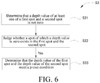
FIG. 6 is a flowchart showing that the controller in the aircraft shown inFIG. 1 determines whether a depth value of a first spot and a depth value of a second spot meet a preset condition; -
FIG. 7 is a flowchart of an obstacle avoidance method according to an embodiment of the present invention; -
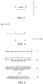
FIG. 8 is a flowchart of determining whether a depth value of a first spot and a depth value of a second spot meet a preset condition in the method shown inFIG. 7 ; -
FIG. 9 is a flowchart of an obstacle avoidance method according to another embodiment of the present invention; and -
FIG. 10 is a structural block diagram of an obstacle avoidance device according to an embodiment of the present invention. - The embodiments of the present invention are described below in detail with reference to the accompanying drawings. It should be noted that when there is no conflict, the embodiments of the present invention and features in the embodiments may be freely combined with each other.
- Steps shown in the flowcharts of the accompanying drawings may be performed in, for example, a computer system of a set of computer executable instructions. Moreover, although logic sequences are shown in the flowcharts, in some cases, the shown or described steps may be performed in sequences different from the sequences herein.
- The embodiments of the present invention provide an obstacle avoidance method and an obstacle avoidance device that may avoid an obstacle by detecting an edge of the obstacle and a moveable object using the obstacle avoidance method or the obstacle avoidance device. The method does not need to establish a map or predict a movement track, and has advantages of a small amount of calculation and high control accuracy.
- As shown in
FIG. 1 , in an embodiment of the present invention, the moveable object is an aircraft. In other possible embodiments, the moveable object may alternatively be a manned aircraft, a robot, an automobile, a boat, a model airplane, an unmanned airship, a fixed-wing aircraft, or an unmanned hot air balloon. The aircraft in this embodiment of the present invention includes ahousing 11, amachine arm 12 connected to thehousing 11, apower device 13 disposed on one end of themachine arm 12, agimbal 15 connected to thehousing 11, animage apparatus 14 connected to thegimbal 13, acontroller 16 disposed in thehousing 11 and adepth sensor 17 connected to thehousing 11. - In this embodiment, there are four
machine arms 12 that is, the aircraft is a four-rotor aircraft. In other possible embodiments, the quantity ofmachine arms 12 may be 3, 6, 8, 10, or the like. - The
power device 13 includes amotor 132 disposed on one end of themachine arm 12 and apropeller 131 connected to a rotating shaft of themotor 132. The rotating shaft of themotor 132 rotates to drive thepropeller 131 to rotate, so as to provide a lifting force for anaircraft 10. - The
gimbal 15 is configured to alleviate or ever eliminate vibration transferred by thepower device 13 to theimage apparatus 14, so as to ensure that theimage apparatus 14 can shoot a stable and clear image or video. - The
image apparatus 14 may be a binocular camera, a monocular camera, an infrared image apparatus, an ultraviolet image apparatus, a video camera, or a similar apparatus. Theimage apparatus 14 may be directly carried on theaircraft 10, or may be carried on theaircraft 10 by using thegimbal 15 shown in this embodiment. Thegimbal 15 permits theimage apparatus 14 to rotate around at least one shaft relative to theaircraft 10. - The
depth sensor 17 may be a binocular camera, a laser radar, a structured light depth camera, or a TOF depth camera. - As shown in
FIG. 2 , first, thedepth sensor 17 scans an area containing an obstacle, to obtain a depth value of a spot in the area. The depth value represents a distance between a spot in the area and the aircraft. In an embodiment of the present invention, the depth value being zero represents that thedepth sensor 17 does not scan an obstacle. - An area between two dashed lines on outermost sides in
FIG. 2 is an angle-of-view range of thedepth sensor 17, and thedepth sensor 17 can scan only within the angle-of-view range. Therefore, during scanning, the obstacle needs to be placed within the angle-of-view range of thedepth sensor 17. Thedepth sensor 17 may scan along a direction from left to right or from right to left, that is, a horizontal direction inFIG. 2 , or may scan along a direction from top to bottom or from bottom to top, that is, a vertical direction. In other possible embodiments, thedepth sensor 17 may even scan along any direction. -
FIG. 3 is an image that is obtained by scanning along the horizontal direction by thedepth sensor 17 and contains an obstacle, andFIG. 4 is a depth view corresponding to the image shown inFIG. 3 . InFIG. 3 , when thedepth sensor 17 scans along the horizontal direction, because there is no obstacle on a left side of a spot A, a depth value corresponding to a spot in the area inFIG. 4 is zero. When thedepth sensor 17 scans at an angle θ1, that is, the spot A, because the spot A is a spot on the obstacle, there is a corresponding value d(θ1) inFIG. 4 . When thedepth sensor 17 continues to scan at an angle θ2, that is, a spot B, because the spot B is a spot on the obstacle, there is a corresponding value d(θ2) inFIG. 4 . There is no obstacle on a right side of the spot B, and therefore, a depth value of a spot in the area is correspondingly zero inFIG. 4 . In addition, a surface of the obstacle is a horizontal plane, and therefore, depth values of spots from the spot A to the spot B on the obstacle are equal. It may be understood that when the surface of the obstacle is not a horizontal plane, the depth values of the spots between the spot A and the spot B are not equal, and a line connecting the spot A to the spot B inFIG. 4 is not a horizontal line. - Subsequently, the
controller 16 judges, according to the depth value obtained by thedepth sensor 17, whether an edge of the obstacle exists in the scanned area. - As shown in
FIG. 5 , in an embodiment of the present invention, thecontroller 16 judges whether the edge of the obstacle exists in the scanned area according to the following steps: - S1. Obtain a depth value of a first spot in the scanned area.
- S2. Obtain a depth value of a second spot adjacent to the first spot in the scanned area.
- The first spot and the second spot may be randomly selected in the scanned area of the
depth sensor 17, and the depth values of both the first spot and the second spot may be obtained according to scan results of thedepth sensor 17. - S3. Judge whether the depth value of the first spot and the depth value of the second spot meet a preset condition.
- As shown in
FIG. 6 , in an embodiment of the present invention, thecontroller 16 may further determine whether the depth value of the first spot and the depth value of the second spot meet a preset condition according to the following steps:
S31. Determine that the depth value of at least one of the first spot and the second spot is not zero. - In an embodiment of the present invention, determining that the depth value of at least one of the first spot and the second spot is not zero is performed by calculating whether an absolute value of a difference between the depth value of the first spot and the depth value of the second spot is greater than a preset value. The preset value is a value greater than but not equal to zero. In other possible embodiments, determining that the depth value of at least one of the first spot and the second spot is not zero may alternatively be performed by judging whether a sum of the depth value of the first spot and the depth value of the second spot is greater than zero. If the sum of the depth values of the two spots is greater than zero, it may be determined that the depth value of at least one of the first spot and the second spot is not zero.
- An objective of performing this step is to ensure that at least one of the two selected spots falls on the obstacle.
- S32. Judge whether a spot of which a depth value is zero exists in the first spot and the second spot.
- In an embodiment of the present invention, judging whether a spot of which a depth value is zero exists in the first spot and the second spot may be performed by judging whether a product of the depth values of the two spots is zero. If the depth value of one of the two spots is zero, the product of the two spots is necessarily zero.
- Based on step S31, an objective of performing this step is to ensure that one of the two selected spots does not fall on the obstacle. The depth value of the spot that does not fall on the obstacle is zero.
- S33. If the spot of which the depth value is zero exists in the first spot and the second spot, determine that the depth value of the first spot and the depth value of the second spot meet the preset condition.
- S4. Judge that an edge of the obstacle exists between the first spot and the second spot.
- There is a depth value jump from the depth value being zero to the depth value not being zero. This means that the edge of the obstacle necessarily exists between the spot of which the depth value is zero and the spot of which the depth value is not zero. For example, in the depth view shown in
FIG. 4 , scanning is started from the left side of the spot A. Because there is no obstacle, the depth value is kept zero. However, when the spot A is scanned, a depth value jump occurs. That is, the depth value jumps from zero to d(θ1). Therefore, it may be obtained that the spot A is a spot on the edge of the obstacle. - In another embodiment of the present invention, the
controller 16 may further judge, in the following manner, whether the edge of the obstacle exists: - determining a first area composed of a spot of which a depth value is zero in an area containing the obstacle;
- determining a second area composed of a spot of which a depth value is not zero in the area containing the obstacle; and
- determining a boundary between the first area and the second area as the edge of the obstacle.
- In other possible embodiments, whether the edge of the obstacle exists may alternatively be determined by judging whether a spot of which a depth value is zero exists in the scanned area. If such a spot exists, it indicates that the edge of the obstacle necessarily exists.
- After determining that the edge exists between the two spots, the
controller 16 obtains an angle at which thedepth sensor 17 scans the edge of the obstacle, that is, an angle at which the depth value suddenly changes; and then determines a flight direction of the aircraft according to the scanning angle. - Using
FIG. 2 as an example, assuming that thedepth sensor 17 scans in a direction from left to right inFIG. 2 , two edges, that is, an edge on a left side and an edge on a right side, of the obstacle may be scanned within a scanning range of thedepth sensor 17. Assuming that a scanning angle at which the edge on the left side is scanned is θ1, a scanning angle at which the edge on the right side is scanned is θ2, and an angle of view of thedepth sensor 17 is θ, then a half angle of view is θ/2. The flight direction of the aircraft directly faces the obstacle, that is, the vertical direction. Therefore, there are two solutions for the aircraft to fly while avoiding the obstacle, one is flying to the left at a yawing angle of θ/2-θ1, and the other one is flying to the right at a yawing angle of θ2-θ/2. It can be learned from the figure that |θ2-θ/2| is less than |θ/2-θ1|. Therefore, it is optimal for the aircraft to fly to the right at the yawing angle of θ/2-θ1. It may be understood that in another embodiment of the present invention, the aircraft may alternatively fly to the left at the yawing angle of θ/2-θ1. - As shown in
FIG. 7 , an embodiment of the present invention further provides an obstacle avoidance method. The method is applied to a moveable object, and includes the following steps: - S10. Scan an area containing an obstacle by using a depth sensor, to obtain a depth value of a spot in the area, the depth value representing a distance between the spot and a moveable object.
- S11. Obtain a depth value of a first spot in the area.
- S12. Obtain a depth value of a second spot adjacent to the first spot in the area.
- S13. Judge whether the depth value of the first spot and the depth value of the second spot meet a preset condition.
- As shown in
FIG. 8 , in an embodiment of the present invention, whether the depth value of the first spot and the depth value of the second spot meet the preset condition may be determined according to the following steps:
S131. Determine that the depth value of at least one of the first spot and the second spot is not zero. - In an embodiment of the present invention, determining that the depth value of at least one of the first spot and the second spot is not zero is performed by calculating whether an absolute value of a difference between the depth value of the first spot and the depth value of the second spot is greater than a preset value. The preset value is a value greater than but not equal to zero. In other possible embodiments, determining that the depth value of at least one of the first spot and the second spot is not zero may alternatively be performed by judging whether a sum of the depth value of the first spot and the depth value of the second spot is greater than zero. If the sum of the depth values of the two spots is greater than zero, it may be determined that the depth value of at least one of the first spot and the second spot is not zero.
- An objective of performing this step is to ensure that at least one of the two selected spots falls on the obstacle.
- S132. Judge whether a spot of which a depth value is zero exists in the first spot and the second spot.
- In an embodiment of the present invention, judging whether a spot of which a depth value is zero exists in the first spot and the second spot may be performed by judging whether a product of the depth values of the two spots is zero. If the depth value of one of the two spots is zero, the product of the two spots is necessarily zero.
- Based on step S131, an objective of performing this step is to ensure that one of the two selected spots does not fall on the obstacle. The depth value of the spot that does not fall on the obstacle is zero.
- S133. If the spot of which the depth value is zero exists in the first spot and the second spot, determine that the depth value of the first spot and the depth value of the second spot meet the preset condition.
- S14. If the preset condition is met, judge that an edge of the obstacle exists between the first spot and the second spot.
- There is a depth value jump from the depth value being zero to the depth value not being zero. This means that the edge of the obstacle necessarily exists between the spot of which the depth value is zero and the spot of which the depth value is not zero. For example, in the depth view shown in
FIG. 4 , scanning is started from the left side of the spot A. Because there is no obstacle, the depth value is kept zero. However, when the spot A is scanned, a depth value jump occurs. That is, the depth value jumps from zero to d(θ1). Therefore, it may be obtained that the spot A is a spot on the edge of the obstacle. - In another embodiment of the present invention, the
controller 16 may further judge, in the following manner, whether the edge of the obstacle exists: - determining a first area composed of a spot of which a depth value is zero in the area containing the obstacle;
- determining a second area composed of a spot of which a depth value is not zero in the area containing the obstacle; and
- determining a boundary between the first area and the second area as the edge of the obstacle.
- In other possible embodiments, whether the edge of the obstacle exists may alternatively be determined by judging whether a spot of which a depth value is zero exists in the scanned area. If such a spot exists, it indicates that the edge of the obstacle necessarily exists.
- S15. Obtain a scanning angle at which the depth sensor scans the edge of the obstacle.
- S16. Determine a movement direction of the moveable object according to the scanning angle.
- In an embodiment of the present invention, the movement direction of the moveable object may be determined according to the following steps:
- S161. Calculate a difference between the scanning angle at which the depth sensor scans the edge of the obstacle and a half angle of view of the depth sensor.
- S162. Select a minimum value in the absolute value.
- S163. Adjust a heading direction of the moveable object according to the minimum value in the absolute value, to enable the moveable object to fly to a side of the edge of the obstacle.
- For detailed content about the steps in the method, reference may be made to the foregoing description, and details are not described herein again.
- As shown in
FIG. 9 , another embodiment of the present invention provides an obstacle avoidance method. The method is applied to a moveable object, and includes the following steps: - S20. Obtain a depth value of a spot in an area containing an obstacle, the depth value representing a distance between the spot and a moveable object.
- S21. Judge, according to the depth value, whether an edge of the obstacle exists in the area.
- S22. If the edge of the obstacle exists, determine a movement direction of the moveable object according to the edge of the obstacle, so as to avoid the obstacle.
- For detailed content about the steps in the method, reference may be made to the foregoing description, and details are not described herein again.
-
FIG. 10 is a structural block diagram of an obstacle avoidance device in an embodiment of the present invention. The obstacle avoidance device includes: - an obtaining
module 30, configured to obtain a depth value of a spot in an area containing an obstacle, the depth value representing a distance between the spot and a moveable object; - a judging
module 31, configured to judge, according to the depth value, whether an edge of the obstacle exists in the area; and - a determining
module 32, configured to determine a movement direction of the moveable object according to the edge, so as to avoid the obstacle. - Optionally, the judging module is specifically configured to:
- judge whether a spot of which a depth value is zero exists in the area; and
- if the spot of which the depth value is zero exists, determine that the edge of the obstacle exists.
- Optionally, the judging module is specifically configured to:
- determine a first area composed of a spot of which a depth value is zero in the area;
- determine a second area composed of a spot of which a depth value is not zero in the area; and
- determine a boundary between the first area and the second area as the edge of the obstacle.
- Optionally, the judging module is specifically configured to:
- obtain a depth value of a first spot in the area;
- obtain a depth value of a second spot adjacent to the first spot in the area;
- judge whether the depth value of the first spot and the depth value of the second spot meet a preset condition; and
- if the depth value of the first spot and the depth value of the second spot meet the preset condition, judge that the edge of the obstacle exists between the first spot and the second spot.
- Optionally, the judging module is specifically configured to:
- determine that the depth value of at least one of the first spot and the second spot is not zero;
- judge whether a spot of which a depth value is zero exists in the first spot and the second spot; and
- if the spot of which the depth value is zero exists in the first spot and the second spot, determine that the depth value of the first spot and the depth value of the second spot meet the preset condition.
- Optionally, the judging module is specifically configured to:
determine that an absolute value of a difference between the depth value of the first spot and the depth value of the second spot is greater than a preset value. - Optionally, the preset value is a value greater than zero.
- Optionally, the judging module is specifically configured to:
determine that a sum of the depth value of the first spot and the depth value of the second spot is greater than zero. - Optionally, the judging module is specifically configured to:
- determine whether a product of the depth values of the two spots is zero; and
- if the product is zero, determine that the spot of which the depth value is zero exists in the first spot and the second spot.
- Optionally, the obtaining module scans the area by using a depth sensor, to obtain the depth value of the spot.
- Optionally, the depth sensor includes at least one of the following:
a binocular camera, a laser radar, a structured light depth camera, or a TOF depth camera. - Optionally, the determining module is configured to:
- obtain a scanning angle at which the depth sensor scans the edge of the obstacle; and
- determine the movement direction of the moveable object according to the scanning angle.
- Optionally, the determining module is specifically configured to:
- calculate a difference between the scanning angle at which the depth sensor scans the edge of the obstacle and a half angle of view of the depth sensor;
- select a minimum value in the absolute value; and
- adjust a heading direction of the moveable object according to the minimum value in the absolute value, to enable the moveable object to fly to a side of the edge of the obstacle.
- Optionally, the obtaining module scans, by using the depth sensor, the area in a horizontal direction, a vertical direction, or any other direction, to obtain the depth value of the spot.
- Optionally, the moveable object includes any of the following:
a manned aircraft, an unmanned aircraft, a robot, an automobile, or a boat. - In an embodiment of the present invention, the obtaining
module 30 may include the depth sensor. The judgingmodule 31 and acontrol module 32 may be controllers. - An embodiment of the present invention further provides an aircraft including a memory and a processor. The memory stores a computer program, and when the computer program is executed by the processor, the processor is enabled to execute the method described in the embodiment shown in
FIG. 7 orFIG. 9 . - An embodiment of the present invention further provides a computer readable storage medium that stores a computer program. When the computer program is executed by a processor, the processor is enabled to execute the method described in the embodiment shown in
FIG. 7 orFIG. 9 . - Although the aircraft is disclosed above in the implementations of the present invention, the content is merely the implementations adopted to facilitate understanding of the present invention, and is not intended to limit the present invention. Any person skilled in the art may make various variations and modifications to the forms and details of implementations without departing from the spirit and scope disclosed in the present invention. However, the patent protection scope of the present invention still should fall within the scope defined by the appended claims.
Claims (47)
- An obstacle avoidance method, applied to a moveable object, and comprising:obtaining a depth value of a spot in an area containing an obstacle, the depth value representing a distance between the spot and the moveable object;judging, according to the depth value, whether an edge of the obstacle exists in the area; andif the edge of the obstacle exists in the area, determining a movement direction of the moveable object according to the edge, so as to avoid the obstacle.
- The obstacle avoidance method according to claim 1, wherein the judging, according to the depth value, whether an edge of the obstacle exists in the area comprises:judging whether a spot of which a depth value is zero exists in the area; andif the spot of which the depth value is zero exists, determining that the edge of the obstacle exists.
- The obstacle avoidance method according to claim 1, wherein the judging, according to the depth value, whether an edge of the obstacle exists in the area comprises:determining a first area composed of a spot of which a depth value is zero in the area;determining a second area composed of a spot of which a depth value is not zero in the area; anddetermining a boundary between the first area and the second area as the edge of the obstacle.
- The obstacle avoidance method according to claim 1, wherein the judging, according to the depth value, whether an edge of the obstacle exists in the area comprises:obtaining a depth value of a first spot in the area;obtaining a depth value of a second spot adjacent to the first spot in the area;judging whether the depth value of the first spot and the depth value of the second spot meet a preset condition; andif the depth value of the first spot and the depth value of the second spot meet the preset condition, judging that the edge of the obstacle exists between the first spot and the second spot.
- The obstacle avoidance method according to claim 4, wherein the judging whether the depth value of the first spot and the depth value of the second spot meet a preset condition comprises:determining that the depth value of at least one of the first spot and the second spot is not zero;judging whether a spot of which a depth value is zero exists in the first spot and the second spot; andif the spot of which the depth value is zero exists in the first spot and the second spot, determining that the depth value of the first spot and the depth value of the second spot meet the preset condition.
- The obstacle avoidance method according to claim 5, wherein the determining that the depth value of at least one of the first spot and the second spot is not zero comprises:
determining that an absolute value of a difference between the depth value of the first spot and the depth value of the second spot is greater than a preset value. - The obstacle avoidance method according to claim 6, wherein the preset value is a value greater than zero.
- The obstacle avoidance method according to claim 5, wherein the determining that the depth value of at least one of the first spot and the second spot is not zero comprises:
determining that a sum of the depth value of the first spot and the depth value of the second spot is greater than zero. - The obstacle avoidance method according to any of claims 5 to 8, wherein the judging whether a spot of which a depth value is zero exists in the first spot and the second spot comprises:determining whether a product of the depth values of the two spots is zero; andif the product is zero, determining that the spot of which the depth value is zero exists in the first spot and the second spot.
- The obstacle avoidance method according to any of claims 1 to 9, wherein the obtaining a depth value of a spot in an area containing an obstacle comprises:
scanning the area by using a depth sensor, to obtain the depth value of the spot. - The obstacle avoidance method according to claim 10, wherein the depth sensor comprises at least one of the following:
a binocular camera, a laser radar, a structured light depth camera, or a time of flight (TOF) depth camera. - The obstacle avoidance method according to claim 10 or 11, wherein the determining a movement direction of the moveable object according to the edge comprises:obtaining a scanning angle at which the depth sensor scans the edge of the obstacle; anddetermining the movement direction of the moveable object according to the scanning angle.
- The obstacle avoidance method according to claim 12, wherein the determining the movement direction of the moveable object according to the scanning angle comprises:calculating an absolute value of a difference between the scanning angle at which the depth sensor scans the edge of the obstacle and a half angle of view of the depth sensor;selecting a minimum value in the absolute value; andadjusting a heading direction of the moveable object according to the minimum value in the absolute value, to enable the moveable object to fly to a side of the edge of the obstacle.
- The obstacle avoidance method according to any of claims 10 to 13, wherein the scanning the area by using a depth sensor, to obtain the depth value of the spot comprises:
scanning, by using the depth sensor, the area in a horizontal direction, a vertical direction, or any other direction, to obtain the depth value of the spot. - The obstacle avoidance method according to any of claims 1 to 14, wherein the moveable object comprises any of the following:
a manned aircraft, an unmanned aircraft, a robot, an automobile, or a boat. - An obstacle avoidance device, applied to a moveable object, and comprising:an obtaining module, configured to obtain a depth value of a spot in an area containing an obstacle, the depth value representing a distance between the spot and the moveable object;a judging module, configured to judge, according to the depth value, whether an edge of the obstacle exists in the area; anda determining module, configured to determine a movement direction of the moveable object according to the edge, so as to avoid the obstacle.
- The obstacle avoidance device according to claim 16, wherein the judging module is specifically configured to:judge whether a spot of which a depth value is zero exists in the area; andif the spot of which the depth value is zero exists, determine that the edge of the obstacle exists.
- The obstacle avoidance device according to claim 16, wherein the judging module is specifically configured to:determine a first area composed of a spot of which a depth value is zero in the area;determine a second area composed of a spot of which a depth value is not zero in the area; anddetermine a boundary between the first area and the second area as the edge of the obstacle.
- The obstacle avoidance device according to claim 16, wherein the judging module is specifically configured to:obtain a depth value of a first spot in the area;obtain a depth value of a second spot adjacent to the first spot in the area;judge whether the depth value of the first spot and the depth value of the second spot meet a preset condition; andif the depth value of the first spot and the depth value of the second spot meet the preset condition, judge that the edge of the obstacle exists between the first spot and the second spot.
- The obstacle avoidance device according to claim 19, wherein the judging module is specifically configured to:determine that the depth value of at least one of the first spot and the second spot is not zero;judge whether a spot of which a depth value is zero exists in the first spot and the second spot; andif the spot of which the depth value is zero exists in the first spot and the second spot, determine that the depth value of the first spot and the depth value of the second spot meet the preset condition.
- The obstacle avoidance device according to claim 20, wherein the judging module is specifically configured to:
determine that an absolute value of a difference between the depth value of the first spot and the depth value of the second spot is greater than a preset value. - The obstacle avoidance device according to claim 21, wherein the preset value is a value greater than zero.
- The obstacle avoidance device according to claim 20, wherein the judging module is specifically configured to:
determine that a sum of the depth value of the first spot and the depth value of the second spot is greater than zero. - The obstacle avoidance device according to any of claims 20 to 23, wherein the judging module is specifically configured to:determine whether a product of the depth values of the two spots is zero; andif the product is zero, determine that the spot of which the depth value is zero exists in the first spot and the second spot.
- The obstacle avoidance device according to any of claims 16 to 24, wherein the obtaining module scans the area by using a depth sensor, to obtain the depth value of the spot.
- The obstacle avoidance device according to claim 25, wherein the depth sensor comprises at least one of the following:
a binocular camera, a laser radar, a structured light depth camera, or a TOF depth camera. - The obstacle avoidance device according to claim 25 or 27, wherein the determining module is configured to:obtain a scanning angle at which the depth sensor scans the edge of the obstacle; anddetermine the movement direction of the moveable object according to the scanning angle.
- The obstacle avoidance device according to claim 27, wherein the determining module is specifically configured to:calculate a difference between the scanning angle at which the depth sensor scans the edge of the obstacle and a half angle of view of the depth sensor;select a minimum value in the absolute value; andadjust a heading direction of the moveable object according to the minimum value in the absolute value, to enable the moveable object to fly to a side of the edge of the obstacle.
- The obstacle avoidance device according to any of claims 25 to 28, wherein the obtaining module scans, by using the depth sensor, the area in a horizontal direction, a vertical direction, or any other direction, to obtain the depth value of the spot.
- The obstacle avoidance device according to any of claims 16 to 29, wherein the moveable object comprises any of the following:
a manned aircraft, an unmanned aircraft, a robot, an automobile, or a boat. - A moveable object, comprising a main body and a depth sensor connected to the main body, wherein
the depth sensor is configured to obtain a depth value of a spot in an area containing an obstacle, the depth value representing a distance between the spot and the moveable object; and
the moveable object further comprises a controller, the controller being configured to:judge, according to the depth value, whether an edge of the obstacle exists in the area; andif the edge of the obstacle exists in the area, determine a movement direction of the moveable object according to the edge, so as to avoid the obstacle. - The moveable object according to claim 31, wherein the controller is specifically configured to:judge whether a spot of which a depth value is zero exists in the area; andif the spot of which the depth value is zero exists, determine that the edge of the obstacle exists.
- The moveable object according to claim 31, wherein the controller is specifically configured to:determine a first area composed of a spot of which a depth value is zero in the area;determine a second area composed of a spot of which a depth value is not zero in the area; anddetermine a boundary between the first area and the second area as the edge of the obstacle.
- The moveable object according to claim 31, wherein the controller is specifically configured to:obtain a depth value of a first spot in the area;obtain a depth value of a second spot adjacent to the first spot in the area;judge whether the depth value of the first spot and the depth value of the second spot meet a preset condition; andif the depth value of the first spot and the depth value of the second spot meet the preset condition, judge that the edge of the obstacle exists between the first spot and the second spot.
- The moveable object according to claim 34, wherein the controller is specifically configured to:determine that the depth value of at least one of the first spot and the second spot is not zero;judge whether a spot of which a depth value is zero exists in the first spot and the second spot; andif the spot of which the depth value is zero exists in the first spot and the second spot, determine that the depth value of the first spot and the depth value of the second spot meet the preset condition.
- The moveable object according to claim 35, wherein the controller is specifically configured to:
determine that an absolute value of a difference between the depth value of the first spot and the depth value of the second spot is greater than a preset value. - The moveable object according to any one of claim 36, wherein the preset value is a value greater than zero.
- The moveable object according to claim 35, wherein the controller is specifically configured to:
determine that a sum of the depth value of the first spot and the depth value of the second spot is greater than zero. - The moveable object according to any of claims 35 to 38, wherein the controller is specifically configured to:determine whether a product of the depth values of the two spots is zero; andif the product is zero, determine that the spot of which the depth value is zero exists in the first spot and the second spot.
- The obstacle avoidance device according to any of claims 31 to 39, wherein the controller is configured to scan the area by using the depth sensor, to obtain the depth value of the spot.
- The moveable object according to claim 40, wherein the depth sensor comprises at least one of the following:
a binocular camera, a laser radar, a structured light depth camera, or a TOF depth camera. - The moveable object according to claim 40 or 41, wherein the controller is specifically configured to:obtain a scanning angle at which the depth sensor scans the edge of the obstacle; anddetermine the movement direction of the moveable object according to the scanning angle.
- The moveable object according to claim 42, wherein the controller is specifically configured to:calculate a difference between the scanning angle at which the depth sensor scans the edge of the obstacle and a half angle of view of the depth sensor;select a minimum value in the absolute value; andadjust a heading direction of the moveable object according to the minimum value in the absolute value, to enable the moveable object to fly to a side of the edge of the obstacle.
- The moveable object according to any of claims 40 to 43, wherein the controller scans, by using the depth sensor, the area in a horizontal direction, a vertical direction, or any other direction, to obtain the depth value of the spot.
- The moveable object according to any of claims 31 to 44, wherein the moveable object comprises any of the following:
a manned aircraft, an unmanned aircraft, a robot, an automobile, or a boat. - A moveable object, comprising a memory and a processor, wherein the memory stores a computer program, and when the computer program is executed by the processor, the processor is enabled to execute the method according to any of claims 1 to 15.
- A computer readable storage medium, storing a computer program, wherein when the computer program is executed by a processor, the processor implements the method according to any of claims 1 to 15.
Applications Claiming Priority (1)
| Application Number | Priority Date | Filing Date | Title |
|---|---|---|---|
| PCT/CN2017/109125 WO2019084868A1 (en) | 2017-11-02 | 2017-11-02 | Obstacle avoidance method and apparatus, movable object, and computer-readable storage medium |
Publications (3)
| Publication Number | Publication Date |
|---|---|
| EP3508936A1 true EP3508936A1 (en) | 2019-07-10 |
| EP3508936A4 EP3508936A4 (en) | 2019-07-10 |
| EP3508936B1 EP3508936B1 (en) | 2020-03-18 |
Family
ID=62040387
Family Applications (1)
| Application Number | Title | Priority Date | Filing Date |
|---|---|---|---|
| EP17814294.9A Active EP3508936B1 (en) | 2017-11-02 | 2017-11-02 | Obstacle avoidance method and apparatus, movable object, and computer-readable storage medium |
Country Status (4)
| Country | Link |
|---|---|
| US (1) | US10672283B2 (en) |
| EP (1) | EP3508936B1 (en) |
| CN (1) | CN107995962B (en) |
| WO (1) | WO2019084868A1 (en) |
Families Citing this family (10)
| Publication number | Priority date | Publication date | Assignee | Title |
|---|---|---|---|---|
| CN109271944B (en) | 2018-09-27 | 2021-03-12 | 百度在线网络技术(北京)有限公司 | Obstacle detection method, obstacle detection device, electronic apparatus, vehicle, and storage medium |
| CN109343079A (en) * | 2018-10-30 | 2019-02-15 | 合肥泰禾光电科技股份有限公司 | A kind of ranging barrier-avoiding method and obstacle avoidance apparatus |
| CN110175523B (en) * | 2019-04-26 | 2021-05-14 | 南京华捷艾米软件科技有限公司 | A self-moving robot animal recognition and avoidance method and its storage medium |
| CN110794422B (en) * | 2019-10-08 | 2022-03-29 | 歌尔光学科技有限公司 | Robot data acquisition system and method with TOF imaging module |
| CN111061363A (en) * | 2019-11-21 | 2020-04-24 | 青岛小鸟看看科技有限公司 | a virtual reality system |
| CN113126640B (en) * | 2019-12-31 | 2022-06-28 | 北京三快在线科技有限公司 | Obstacle detection method and device for unmanned aerial vehicle, unmanned aerial vehicle and storage medium |
| CN111260715B (en) * | 2020-01-20 | 2023-09-08 | 深圳市普渡科技有限公司 | Depth map processing method, small obstacle detection method and system |
| CN111562567B (en) | 2020-05-11 | 2021-04-30 | 北京驭光科技发展有限公司 | Obstacle detection system of mobile device, mobile device and sweeping robot |
| WO2021237535A1 (en) * | 2020-05-27 | 2021-12-02 | 深圳市大疆创新科技有限公司 | Collision processing method and device, and medium |
| CN112781595B (en) * | 2021-01-12 | 2023-08-01 | 北京航空航天大学 | Indoor airship positioning and obstacle avoidance system based on depth camera |
Family Cites Families (18)
| Publication number | Priority date | Publication date | Assignee | Title |
|---|---|---|---|---|
| US6678394B1 (en) * | 1999-11-30 | 2004-01-13 | Cognex Technology And Investment Corporation | Obstacle detection system |
| US20100121574A1 (en) * | 2006-09-05 | 2010-05-13 | Honeywell International Inc. | Method for collision avoidance of unmanned aerial vehicle with other aircraft |
| US9442485B1 (en) * | 2014-08-13 | 2016-09-13 | Trace Live Network Inc. | Pixel based image tracking system for unmanned aerial vehicle (UAV) action camera system |
| US20170023946A1 (en) * | 2015-04-09 | 2017-01-26 | Goodrich Corporation | Flight control system with dual redundant lidar |
| US10106939B2 (en) * | 2015-04-22 | 2018-10-23 | Neusch Innovations, Lp | Brace and beam anti-ram passive vehicle barrier |
| US20170045613A1 (en) * | 2015-08-11 | 2017-02-16 | Zongbo Wang | 360-degree electronic scan radar for collision avoidance in unmanned aerial vehicles |
| CN105389543A (en) * | 2015-10-19 | 2016-03-09 | 广东工业大学 | Mobile robot obstacle avoidance device based on all-dimensional binocular vision depth information fusion |
| WO2017106875A1 (en) * | 2015-12-18 | 2017-06-22 | Gerard Dirk Smits | Real time position sensing of objects |
| US10665115B2 (en) * | 2016-01-05 | 2020-05-26 | California Institute Of Technology | Controlling unmanned aerial vehicles to avoid obstacle collision |
| CN106052674B (en) * | 2016-05-20 | 2019-07-26 | 青岛克路德机器人有限公司 | A kind of SLAM method and system of Indoor Robot |
| US10212346B2 (en) * | 2016-06-08 | 2019-02-19 | Amazon Technologies, Inc. | Multi-sensor image stabilization techniques |
| CN105955303A (en) * | 2016-07-05 | 2016-09-21 | 北京奇虎科技有限公司 | UAV autonomous obstacle avoidance method and device |
| CN105955304B (en) * | 2016-07-06 | 2024-11-08 | 零度智控(北京)智能科技有限公司 | Obstacle avoidance method, obstacle avoidance device and unmanned aerial vehicle |
| CN106054900B (en) * | 2016-08-08 | 2018-11-09 | 电子科技大学 | The interim barrier-avoiding method of robot based on depth camera |
| US11295458B2 (en) * | 2016-12-01 | 2022-04-05 | Skydio, Inc. | Object tracking by an unmanned aerial vehicle using visual sensors |
| CN106960454B (en) * | 2017-03-02 | 2021-02-12 | 武汉星巡智能科技有限公司 | Depth of field obstacle avoidance method and equipment and unmanned aerial vehicle |
| CN106843282B (en) * | 2017-03-17 | 2020-11-03 | 东南大学 | Regional complete search and obstacle avoidance system and method based on M100 development platform |
| CN107229903B (en) * | 2017-04-17 | 2020-11-03 | 深圳奥比中光科技有限公司 | Robot obstacle avoidance method and device and storage device |
-
2017
- 2017-11-02 EP EP17814294.9A patent/EP3508936B1/en active Active
- 2017-11-02 WO PCT/CN2017/109125 patent/WO2019084868A1/en not_active Ceased
- 2017-11-02 CN CN201780001751.7A patent/CN107995962B/en active Active
-
2018
- 2018-01-30 US US15/883,514 patent/US10672283B2/en active Active
Also Published As
| Publication number | Publication date |
|---|---|
| EP3508936B1 (en) | 2020-03-18 |
| WO2019084868A1 (en) | 2019-05-09 |
| US10672283B2 (en) | 2020-06-02 |
| EP3508936A4 (en) | 2019-07-10 |
| US20190130773A1 (en) | 2019-05-02 |
| CN107995962B (en) | 2021-06-22 |
| CN107995962A (en) | 2018-05-04 |
Similar Documents
| Publication | Publication Date | Title |
|---|---|---|
| EP3508936A1 (en) | Obstacle avoidance method and apparatus, movable object, and computer-readable storage medium | |
| US12217500B2 (en) | Automatic terrain evaluation of landing surfaces, and associated systems and methods | |
| EP3818337B1 (en) | Defect detection system using a camera equipped uav for building facades on complex asset geometry with optimal automatic obstacle deconflicted flightpath | |
| CN106774301B (en) | Obstacle avoidance following method and electronic equipment | |
| CN105652891B (en) | A kind of rotor wing unmanned aerial vehicle movement Target self-determination tracks of device and its control method | |
| CN113012219B (en) | Information processing apparatus, information processing method, and computer readable medium | |
| JP5990453B2 (en) | Autonomous mobile robot | |
| CN112789672A (en) | Control and navigation system, attitude optimization, mapping and positioning technology | |
| JP2017075863A (en) | Flight type inspection apparatus and inspection method | |
| JP6140458B2 (en) | Autonomous mobile robot | |
| JP6014484B2 (en) | Autonomous mobile robot | |
| CN119002507B (en) | Photovoltaic cleaning robot and driving method thereof | |
| Ortiz et al. | Vessel inspection: A micro-aerial vehicle-based approach | |
| US20210088652A1 (en) | Vehicular monitoring systems and methods for sensing external objects | |
| US20230095700A1 (en) | Vehicle flight control method and apparatus for unmanned aerial vehicle, and unmanned aerial vehicle | |
| WO2018099259A1 (en) | Method and device for obstacle detection for unmanned aerial vehicle | |
| US11423560B2 (en) | Method for improving the interpretation of the surroundings of a vehicle | |
| KR20230070989A (en) | Method, system, and non-transitory computer-readable recording medium for controlling a robot | |
| JP7358108B2 (en) | Information processing device, information processing method and program | |
| Yue et al. | Vision-based autonomous landing of uav on dynamic apron | |
| JP7618378B2 (en) | Autonomous Vehicles | |
| EP4134774B1 (en) | Information processing apparatus, moving body, method for controlling information processing apparatus, and program | |
| WO2021056144A1 (en) | Method and apparatus for controlling return of movable platform, and movable platform | |
| US20250180751A1 (en) | Unmanned aerial device and operation method thereof |
Legal Events
| Date | Code | Title | Description |
|---|---|---|---|
| STAA | Information on the status of an ep patent application or granted ep patent |
Free format text: STATUS: UNKNOWN |
|
| STAA | Information on the status of an ep patent application or granted ep patent |
Free format text: STATUS: THE INTERNATIONAL PUBLICATION HAS BEEN MADE |
|
| PUAI | Public reference made under article 153(3) epc to a published international application that has entered the european phase |
Free format text: ORIGINAL CODE: 0009012 |
|
| STAA | Information on the status of an ep patent application or granted ep patent |
Free format text: STATUS: REQUEST FOR EXAMINATION WAS MADE |
|
| 17P | Request for examination filed |
Effective date: 20171228 |
|
| A4 | Supplementary search report drawn up and despatched |
Effective date: 20190104 |
|
| AK | Designated contracting states |
Kind code of ref document: A1 Designated state(s): AL AT BE BG CH CY CZ DE DK EE ES FI FR GB GR HR HU IE IS IT LI LT LU LV MC MK MT NL NO PL PT RO RS SE SI SK SM TR |
|
| AX | Request for extension of the european patent |
Extension state: BA ME |
|
| GRAP | Despatch of communication of intention to grant a patent |
Free format text: ORIGINAL CODE: EPIDOSNIGR1 |
|
| STAA | Information on the status of an ep patent application or granted ep patent |
Free format text: STATUS: GRANT OF PATENT IS INTENDED |
|
| RIC1 | Information provided on ipc code assigned before grant |
Ipc: G08G 5/00 20060101ALI20190924BHEP Ipc: B64C 39/02 20060101ALI20190924BHEP Ipc: H04N 7/18 20060101ALI20190924BHEP Ipc: G05D 1/02 20060101AFI20190924BHEP Ipc: G05D 1/10 20060101ALI20190924BHEP Ipc: G08G 5/04 20060101ALI20190924BHEP |
|
| DAV | Request for validation of the european patent (deleted) | ||
| DAX | Request for extension of the european patent (deleted) | ||
| INTG | Intention to grant announced |
Effective date: 20191014 |
|
| GRAS | Grant fee paid |
Free format text: ORIGINAL CODE: EPIDOSNIGR3 |
|
| GRAA | (expected) grant |
Free format text: ORIGINAL CODE: 0009210 |
|
| STAA | Information on the status of an ep patent application or granted ep patent |
Free format text: STATUS: THE PATENT HAS BEEN GRANTED |
|
| AK | Designated contracting states |
Kind code of ref document: B1 Designated state(s): AL AT BE BG CH CY CZ DE DK EE ES FI FR GB GR HR HU IE IS IT LI LT LU LV MC MK MT NL NO PL PT RO RS SE SI SK SM TR |
|
| REG | Reference to a national code |
Ref country code: GB Ref legal event code: FG4D |
|
| REG | Reference to a national code |
Ref country code: DE Ref legal event code: R096 Ref document number: 602017013394 Country of ref document: DE |
|
| REG | Reference to a national code |
Ref country code: AT Ref legal event code: REF Ref document number: 1246649 Country of ref document: AT Kind code of ref document: T Effective date: 20200415 Ref country code: IE Ref legal event code: FG4D |
|
| PG25 | Lapsed in a contracting state [announced via postgrant information from national office to epo] |
Ref country code: NO Free format text: LAPSE BECAUSE OF FAILURE TO SUBMIT A TRANSLATION OF THE DESCRIPTION OR TO PAY THE FEE WITHIN THE PRESCRIBED TIME-LIMIT Effective date: 20200618 Ref country code: FI Free format text: LAPSE BECAUSE OF FAILURE TO SUBMIT A TRANSLATION OF THE DESCRIPTION OR TO PAY THE FEE WITHIN THE PRESCRIBED TIME-LIMIT Effective date: 20200318 Ref country code: RS Free format text: LAPSE BECAUSE OF FAILURE TO SUBMIT A TRANSLATION OF THE DESCRIPTION OR TO PAY THE FEE WITHIN THE PRESCRIBED TIME-LIMIT Effective date: 20200318 |
|
| REG | Reference to a national code |
Ref country code: NL Ref legal event code: MP Effective date: 20200318 |
|
| PG25 | Lapsed in a contracting state [announced via postgrant information from national office to epo] |
Ref country code: GR Free format text: LAPSE BECAUSE OF FAILURE TO SUBMIT A TRANSLATION OF THE DESCRIPTION OR TO PAY THE FEE WITHIN THE PRESCRIBED TIME-LIMIT Effective date: 20200619 Ref country code: HR Free format text: LAPSE BECAUSE OF FAILURE TO SUBMIT A TRANSLATION OF THE DESCRIPTION OR TO PAY THE FEE WITHIN THE PRESCRIBED TIME-LIMIT Effective date: 20200318 Ref country code: BG Free format text: LAPSE BECAUSE OF FAILURE TO SUBMIT A TRANSLATION OF THE DESCRIPTION OR TO PAY THE FEE WITHIN THE PRESCRIBED TIME-LIMIT Effective date: 20200618 Ref country code: SE Free format text: LAPSE BECAUSE OF FAILURE TO SUBMIT A TRANSLATION OF THE DESCRIPTION OR TO PAY THE FEE WITHIN THE PRESCRIBED TIME-LIMIT Effective date: 20200318 Ref country code: LV Free format text: LAPSE BECAUSE OF FAILURE TO SUBMIT A TRANSLATION OF THE DESCRIPTION OR TO PAY THE FEE WITHIN THE PRESCRIBED TIME-LIMIT Effective date: 20200318 |
|
| REG | Reference to a national code |
Ref country code: LT Ref legal event code: MG4D |
|
| PG25 | Lapsed in a contracting state [announced via postgrant information from national office to epo] |
Ref country code: NL Free format text: LAPSE BECAUSE OF FAILURE TO SUBMIT A TRANSLATION OF THE DESCRIPTION OR TO PAY THE FEE WITHIN THE PRESCRIBED TIME-LIMIT Effective date: 20200318 |
|
| PG25 | Lapsed in a contracting state [announced via postgrant information from national office to epo] |
Ref country code: CZ Free format text: LAPSE BECAUSE OF FAILURE TO SUBMIT A TRANSLATION OF THE DESCRIPTION OR TO PAY THE FEE WITHIN THE PRESCRIBED TIME-LIMIT Effective date: 20200318 Ref country code: RO Free format text: LAPSE BECAUSE OF FAILURE TO SUBMIT A TRANSLATION OF THE DESCRIPTION OR TO PAY THE FEE WITHIN THE PRESCRIBED TIME-LIMIT Effective date: 20200318 Ref country code: PT Free format text: LAPSE BECAUSE OF FAILURE TO SUBMIT A TRANSLATION OF THE DESCRIPTION OR TO PAY THE FEE WITHIN THE PRESCRIBED TIME-LIMIT Effective date: 20200812 Ref country code: SM Free format text: LAPSE BECAUSE OF FAILURE TO SUBMIT A TRANSLATION OF THE DESCRIPTION OR TO PAY THE FEE WITHIN THE PRESCRIBED TIME-LIMIT Effective date: 20200318 Ref country code: EE Free format text: LAPSE BECAUSE OF FAILURE TO SUBMIT A TRANSLATION OF THE DESCRIPTION OR TO PAY THE FEE WITHIN THE PRESCRIBED TIME-LIMIT Effective date: 20200318 Ref country code: LT Free format text: LAPSE BECAUSE OF FAILURE TO SUBMIT A TRANSLATION OF THE DESCRIPTION OR TO PAY THE FEE WITHIN THE PRESCRIBED TIME-LIMIT Effective date: 20200318 Ref country code: SK Free format text: LAPSE BECAUSE OF FAILURE TO SUBMIT A TRANSLATION OF THE DESCRIPTION OR TO PAY THE FEE WITHIN THE PRESCRIBED TIME-LIMIT Effective date: 20200318 Ref country code: IS Free format text: LAPSE BECAUSE OF FAILURE TO SUBMIT A TRANSLATION OF THE DESCRIPTION OR TO PAY THE FEE WITHIN THE PRESCRIBED TIME-LIMIT Effective date: 20200718 |
|
| REG | Reference to a national code |
Ref country code: AT Ref legal event code: MK05 Ref document number: 1246649 Country of ref document: AT Kind code of ref document: T Effective date: 20200318 |
|
| REG | Reference to a national code |
Ref country code: DE Ref legal event code: R097 Ref document number: 602017013394 Country of ref document: DE |
|
| PLBE | No opposition filed within time limit |
Free format text: ORIGINAL CODE: 0009261 |
|
| STAA | Information on the status of an ep patent application or granted ep patent |
Free format text: STATUS: NO OPPOSITION FILED WITHIN TIME LIMIT |
|
| PG25 | Lapsed in a contracting state [announced via postgrant information from national office to epo] |
Ref country code: DK Free format text: LAPSE BECAUSE OF FAILURE TO SUBMIT A TRANSLATION OF THE DESCRIPTION OR TO PAY THE FEE WITHIN THE PRESCRIBED TIME-LIMIT Effective date: 20200318 Ref country code: IT Free format text: LAPSE BECAUSE OF FAILURE TO SUBMIT A TRANSLATION OF THE DESCRIPTION OR TO PAY THE FEE WITHIN THE PRESCRIBED TIME-LIMIT Effective date: 20200318 Ref country code: AT Free format text: LAPSE BECAUSE OF FAILURE TO SUBMIT A TRANSLATION OF THE DESCRIPTION OR TO PAY THE FEE WITHIN THE PRESCRIBED TIME-LIMIT Effective date: 20200318 Ref country code: ES Free format text: LAPSE BECAUSE OF FAILURE TO SUBMIT A TRANSLATION OF THE DESCRIPTION OR TO PAY THE FEE WITHIN THE PRESCRIBED TIME-LIMIT Effective date: 20200318 |
|
| 26N | No opposition filed |
Effective date: 20201221 |
|
| PG25 | Lapsed in a contracting state [announced via postgrant information from national office to epo] |
Ref country code: PL Free format text: LAPSE BECAUSE OF FAILURE TO SUBMIT A TRANSLATION OF THE DESCRIPTION OR TO PAY THE FEE WITHIN THE PRESCRIBED TIME-LIMIT Effective date: 20200318 |
|
| PG25 | Lapsed in a contracting state [announced via postgrant information from national office to epo] |
Ref country code: SI Free format text: LAPSE BECAUSE OF FAILURE TO SUBMIT A TRANSLATION OF THE DESCRIPTION OR TO PAY THE FEE WITHIN THE PRESCRIBED TIME-LIMIT Effective date: 20200318 |
|
| PG25 | Lapsed in a contracting state [announced via postgrant information from national office to epo] |
Ref country code: MC Free format text: LAPSE BECAUSE OF FAILURE TO SUBMIT A TRANSLATION OF THE DESCRIPTION OR TO PAY THE FEE WITHIN THE PRESCRIBED TIME-LIMIT Effective date: 20200318 |
|
| REG | Reference to a national code |
Ref country code: CH Ref legal event code: PL |
|
| PG25 | Lapsed in a contracting state [announced via postgrant information from national office to epo] |
Ref country code: LU Free format text: LAPSE BECAUSE OF NON-PAYMENT OF DUE FEES Effective date: 20201102 |
|
| REG | Reference to a national code |
Ref country code: BE Ref legal event code: MM Effective date: 20201130 |
|
| PG25 | Lapsed in a contracting state [announced via postgrant information from national office to epo] |
Ref country code: CH Free format text: LAPSE BECAUSE OF NON-PAYMENT OF DUE FEES Effective date: 20201130 Ref country code: LI Free format text: LAPSE BECAUSE OF NON-PAYMENT OF DUE FEES Effective date: 20201130 |
|
| PG25 | Lapsed in a contracting state [announced via postgrant information from national office to epo] |
Ref country code: IE Free format text: LAPSE BECAUSE OF NON-PAYMENT OF DUE FEES Effective date: 20201102 |
|
| PG25 | Lapsed in a contracting state [announced via postgrant information from national office to epo] |
Ref country code: TR Free format text: LAPSE BECAUSE OF FAILURE TO SUBMIT A TRANSLATION OF THE DESCRIPTION OR TO PAY THE FEE WITHIN THE PRESCRIBED TIME-LIMIT Effective date: 20200318 Ref country code: MT Free format text: LAPSE BECAUSE OF FAILURE TO SUBMIT A TRANSLATION OF THE DESCRIPTION OR TO PAY THE FEE WITHIN THE PRESCRIBED TIME-LIMIT Effective date: 20200318 Ref country code: CY Free format text: LAPSE BECAUSE OF FAILURE TO SUBMIT A TRANSLATION OF THE DESCRIPTION OR TO PAY THE FEE WITHIN THE PRESCRIBED TIME-LIMIT Effective date: 20200318 |
|
| PG25 | Lapsed in a contracting state [announced via postgrant information from national office to epo] |
Ref country code: MK Free format text: LAPSE BECAUSE OF FAILURE TO SUBMIT A TRANSLATION OF THE DESCRIPTION OR TO PAY THE FEE WITHIN THE PRESCRIBED TIME-LIMIT Effective date: 20200318 Ref country code: AL Free format text: LAPSE BECAUSE OF FAILURE TO SUBMIT A TRANSLATION OF THE DESCRIPTION OR TO PAY THE FEE WITHIN THE PRESCRIBED TIME-LIMIT Effective date: 20200318 |
|
| PG25 | Lapsed in a contracting state [announced via postgrant information from national office to epo] |
Ref country code: BE Free format text: LAPSE BECAUSE OF NON-PAYMENT OF DUE FEES Effective date: 20201130 |
|
| REG | Reference to a national code |
Ref country code: DE Ref legal event code: R079 Ref document number: 602017013394 Country of ref document: DE Free format text: PREVIOUS MAIN CLASS: G05D0001020000 Ipc: G05D0001430000 |
|
| PGFP | Annual fee paid to national office [announced via postgrant information from national office to epo] |
Ref country code: GB Payment date: 20231123 Year of fee payment: 7 |
|
| GBPC | Gb: european patent ceased through non-payment of renewal fee |
Effective date: 20241102 |
|
| PG25 | Lapsed in a contracting state [announced via postgrant information from national office to epo] |
Ref country code: GB Free format text: LAPSE BECAUSE OF NON-PAYMENT OF DUE FEES Effective date: 20241102 |
|
| PGFP | Annual fee paid to national office [announced via postgrant information from national office to epo] |
Ref country code: DE Payment date: 20251119 Year of fee payment: 9 |
|
| PGFP | Annual fee paid to national office [announced via postgrant information from national office to epo] |
Ref country code: FR Payment date: 20251126 Year of fee payment: 9 |