EP3508934A1 - Distress detection in dynamically and thermally coupled systems - Google Patents
Distress detection in dynamically and thermally coupled systems Download PDFInfo
- Publication number
- EP3508934A1 EP3508934A1 EP19150768.0A EP19150768A EP3508934A1 EP 3508934 A1 EP3508934 A1 EP 3508934A1 EP 19150768 A EP19150768 A EP 19150768A EP 3508934 A1 EP3508934 A1 EP 3508934A1
- Authority
- EP
- European Patent Office
- Prior art keywords
- parameter
- distress
- component
- monitored
- detection
- Prior art date
- Legal status (The legal status is an assumption and is not a legal conclusion. Google has not performed a legal analysis and makes no representation as to the accuracy of the status listed.)
- Granted
Links
Images



Classifications
-
- G—PHYSICS
- G05—CONTROLLING; REGULATING
- G05B—CONTROL OR REGULATING SYSTEMS IN GENERAL; FUNCTIONAL ELEMENTS OF SUCH SYSTEMS; MONITORING OR TESTING ARRANGEMENTS FOR SUCH SYSTEMS OR ELEMENTS
- G05B23/00—Testing or monitoring of control systems or parts thereof
- G05B23/02—Electric testing or monitoring
- G05B23/0205—Electric testing or monitoring by means of a monitoring system capable of detecting and responding to faults
- G05B23/0218—Electric testing or monitoring by means of a monitoring system capable of detecting and responding to faults characterised by the fault detection method dealing with either existing or incipient faults
- G05B23/0243—Electric testing or monitoring by means of a monitoring system capable of detecting and responding to faults characterised by the fault detection method dealing with either existing or incipient faults model based detection method, e.g. first-principles knowledge model
- G05B23/0254—Electric testing or monitoring by means of a monitoring system capable of detecting and responding to faults characterised by the fault detection method dealing with either existing or incipient faults model based detection method, e.g. first-principles knowledge model based on a quantitative model, e.g. mathematical relationships between inputs and outputs; functions: observer, Kalman filter, residual calculation, Neural Networks
-
- F—MECHANICAL ENGINEERING; LIGHTING; HEATING; WEAPONS; BLASTING
- F01—MACHINES OR ENGINES IN GENERAL; ENGINE PLANTS IN GENERAL; STEAM ENGINES
- F01D—NON-POSITIVE DISPLACEMENT MACHINES OR ENGINES, e.g. STEAM TURBINES
- F01D21/00—Shutting-down of machines or engines, e.g. in emergency; Regulating, controlling, or safety means not otherwise provided for
- F01D21/003—Arrangements for testing or measuring
-
- G—PHYSICS
- G06—COMPUTING OR CALCULATING; COUNTING
- G06N—COMPUTING ARRANGEMENTS BASED ON SPECIFIC COMPUTATIONAL MODELS
- G06N5/00—Computing arrangements using knowledge-based models
- G06N5/04—Inference or reasoning models
- G06N5/048—Fuzzy inferencing
-
- F—MECHANICAL ENGINEERING; LIGHTING; HEATING; WEAPONS; BLASTING
- F02—COMBUSTION ENGINES; HOT-GAS OR COMBUSTION-PRODUCT ENGINE PLANTS
- F02C—GAS-TURBINE PLANTS; AIR INTAKES FOR JET-PROPULSION PLANTS; CONTROLLING FUEL SUPPLY IN AIR-BREATHING JET-PROPULSION PLANTS
- F02C7/00—Features, components parts, details or accessories, not provided for in, or of interest apart form groups F02C1/00 - F02C6/00; Air intakes for jet-propulsion plants
- F02C7/06—Arrangements of bearings; Lubricating
-
- F—MECHANICAL ENGINEERING; LIGHTING; HEATING; WEAPONS; BLASTING
- F02—COMBUSTION ENGINES; HOT-GAS OR COMBUSTION-PRODUCT ENGINE PLANTS
- F02C—GAS-TURBINE PLANTS; AIR INTAKES FOR JET-PROPULSION PLANTS; CONTROLLING FUEL SUPPLY IN AIR-BREATHING JET-PROPULSION PLANTS
- F02C7/00—Features, components parts, details or accessories, not provided for in, or of interest apart form groups F02C1/00 - F02C6/00; Air intakes for jet-propulsion plants
- F02C7/26—Starting; Ignition
- F02C7/264—Ignition
-
- F—MECHANICAL ENGINEERING; LIGHTING; HEATING; WEAPONS; BLASTING
- F05—INDEXING SCHEMES RELATING TO ENGINES OR PUMPS IN VARIOUS SUBCLASSES OF CLASSES F01-F04
- F05D—INDEXING SCHEME FOR ASPECTS RELATING TO NON-POSITIVE-DISPLACEMENT MACHINES OR ENGINES, GAS-TURBINES OR JET-PROPULSION PLANTS
- F05D2220/00—Application
- F05D2220/30—Application in turbines
- F05D2220/32—Application in turbines in gas turbines
- F05D2220/323—Application in turbines in gas turbines for aircraft propulsion, e.g. jet engines
-
- F—MECHANICAL ENGINEERING; LIGHTING; HEATING; WEAPONS; BLASTING
- F05—INDEXING SCHEMES RELATING TO ENGINES OR PUMPS IN VARIOUS SUBCLASSES OF CLASSES F01-F04
- F05D—INDEXING SCHEME FOR ASPECTS RELATING TO NON-POSITIVE-DISPLACEMENT MACHINES OR ENGINES, GAS-TURBINES OR JET-PROPULSION PLANTS
- F05D2270/00—Control
- F05D2270/70—Type of control algorithm
- F05D2270/707—Type of control algorithm fuzzy logic
-
- G—PHYSICS
- G05—CONTROLLING; REGULATING
- G05B—CONTROL OR REGULATING SYSTEMS IN GENERAL; FUNCTIONAL ELEMENTS OF SUCH SYSTEMS; MONITORING OR TESTING ARRANGEMENTS FOR SUCH SYSTEMS OR ELEMENTS
- G05B15/00—Systems controlled by a computer
- G05B15/02—Systems controlled by a computer electric
-
- G—PHYSICS
- G05—CONTROLLING; REGULATING
- G05B—CONTROL OR REGULATING SYSTEMS IN GENERAL; FUNCTIONAL ELEMENTS OF SUCH SYSTEMS; MONITORING OR TESTING ARRANGEMENTS FOR SUCH SYSTEMS OR ELEMENTS
- G05B2219/00—Program-control systems
- G05B2219/30—Nc systems
- G05B2219/33—Director till display
- G05B2219/33295—Fuzzy expert system for diagnostic, monitoring
-
- G—PHYSICS
- G05—CONTROLLING; REGULATING
- G05B—CONTROL OR REGULATING SYSTEMS IN GENERAL; FUNCTIONAL ELEMENTS OF SUCH SYSTEMS; MONITORING OR TESTING ARRANGEMENTS FOR SUCH SYSTEMS OR ELEMENTS
- G05B2219/00—Program-control systems
- G05B2219/30—Nc systems
- G05B2219/37—Measurements
- G05B2219/37328—Decentralised data fusion
-
- G—PHYSICS
- G06—COMPUTING OR CALCULATING; COUNTING
- G06Q—INFORMATION AND COMMUNICATION TECHNOLOGY [ICT] SPECIALLY ADAPTED FOR ADMINISTRATIVE, COMMERCIAL, FINANCIAL, MANAGERIAL OR SUPERVISORY PURPOSES; SYSTEMS OR METHODS SPECIALLY ADAPTED FOR ADMINISTRATIVE, COMMERCIAL, FINANCIAL, MANAGERIAL OR SUPERVISORY PURPOSES, NOT OTHERWISE PROVIDED FOR
- G06Q10/00—Administration; Management
- G06Q10/20—Administration of product repair or maintenance
Definitions
- the subject matter disclosed herein generally relates to measurement systems and, more particularly, to a method and an apparatus for distress detection in dynamically and thermally coupled systems.
- Complex machines are composed of multiple systems that are intrinsically dependent. Health monitoring of complex machines typically focuses on systems or subsystems that are linked mechanically, electrically, or by a fluid. Cross coupling effects between systems of a machine can be difficult to accurately model, and thus health monitoring is typically partitioned into discrete blocks that map to particular systems or subsystems. For instance, parameters such as oil temperature and oil pressure may be used to determine a lubrication system health status; however, the impact of such parameters on other systems within a machine may not be readily apparent.
- a distress detection system includes a data repository operable to collect sensor data from a monitored system.
- the distress detection system also includes an analysis system with a processing system operable to access a first parameter of a first system of the monitored system from the data repository and access a second parameter of the first system of the monitored system from the data repository.
- the processing system is also operable to apply fuzzy reasoning rules to evaluate a combination of the first parameter and the second parameter to determine an in-range interaction with respect to a second system of the monitored system as fuzzy metric data points, classify a component of the second system as being in distress based on comparing the fuzzy metric data points to a limit line, and assert a component distress indicator responsive to classifying the component of the second system as being in distress.
- the first system may be thermally cross-coupled to the second system absent a mechanical linkage, an electrical linkage, and a fluid linkage between the first system and the second system.
- the monitored system may be a gas turbine engine.
- the first system may be a lubrication system and the component of the second system may be a burner.
- the first parameter may be a main oil pressure and the second parameter may be a main oil temperature.
- Observations of the first parameter and the second parameter may be constrained based on determining that the first parameter and the second parameter are both within a valid operating range.
- the first parameter and the second parameter may be normalized with respect to a third parameter.
- a maintenance action may be triggered responsive to the component distress indicator being asserted.
- Assertion of the component distress indicator may be prevented based on detection of a fault condition associated with the first system.
- the first parameter and the second parameter may be derived from separate sensors of the monitored system.
- a method of distress detection in a monitored system includes accessing, by an analysis system, a first parameter of a first system of the monitored system.
- the analysis system accesses a second parameter of the first system of the monitored system. Fuzzy reasoning rules are applied to evaluate a combination of the first parameter and the second parameter to determine an in-range interaction with respect to a second system of the monitored system as a plurality of fuzzy metric data points.
- a component of the second system is classified as being in distress based on comparing the fuzzy metric data points to a limit line.
- a component distress indicator is asserted responsive to classifying the component of the second system as being in distress.
- a technical effect of the apparatus, systems and methods is achieved by using data fusion and fuzzy logic to detect distress in dynamically and thermally coupled systems of the same machine as described herein.
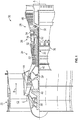
- FIG. 1 schematically illustrates a gas turbine engine 20.
- the gas turbine engine 20 is disclosed herein as a two-spool turbofan that generally incorporates a fan section 22, a compressor section 24, a combustor section 26 and a turbine section 28.
- Alternative engines might include an augmentor section (not shown) among other systems or features.
- the fan section 22 drives air along a bypass flow path B in a bypass duct, while the compressor section 24 drives air along a core flow path C for compression and communication into the combustor section 26 then expansion through the turbine section 28.
- the exemplary engine 20 generally includes a low speed spool 30 and a high speed spool 32 mounted for rotation about an engine central longitudinal axis A relative to an engine static structure 36 via several bearing systems 38. It should be understood that various bearing systems 38 at various locations may alternatively or additionally be provided, and the location of bearing systems 38 may be varied as appropriate to the application.
- the low speed spool 30 generally includes an inner shaft 40 that interconnects a fan 42, a low pressure compressor 44 and a low pressure turbine 46.
- the inner shaft 40 is connected to the fan 42 through a speed change mechanism, which in exemplary gas turbine engine 20 is illustrated as a geared architecture 48 to drive the fan 42 at a lower speed than the low speed spool 30.
- the high speed spool 32 includes an outer shaft 50 that interconnects a high pressure compressor 52 and high pressure turbine 54.
- a combustor 56 is arranged in exemplary gas turbine 20 between the high pressure compressor 52 and the high pressure turbine 54.
- An engine static structure 36 is arranged generally between the high pressure turbine 54 and the low pressure turbine 46.
- the engine static structure 36 further supports bearing systems 38 in the turbine section 28.
- the inner shaft 40 and the outer shaft 50 are concentric and rotate via bearing systems 38 about the engine central longitudinal axis A which is collinear with their longitudinal axes.
- each of the positions of the fan section 22, compressor section 24, combustor section 26, turbine section 28, and fan drive gear system 48 may be varied.
- gear system 48 may be located aft of combustor section 26 or even aft of turbine section 28, and fan section 22 may be positioned forward or aft of the location of gear system 48.
- the engine 20 in one example is a high-bypass geared aircraft engine.
- the engine 20 bypass ratio is greater than about six (6), with an example embodiment being greater than about ten (10)
- the geared architecture 48 is an epicyclic gear train, such as a planetary gear system or other gear system, with a gear reduction ratio of greater than about 2.3
- the low pressure turbine 46 has a pressure ratio that is greater than about five.
- the engine 20 bypass ratio is greater than about ten (10:1)
- the fan diameter is significantly larger than that of the low pressure compressor 44
- the low pressure turbine 46 has a pressure ratio that is greater than about five 5:1.
- Low pressure turbine 46 pressure ratio is pressure measured prior to inlet of low pressure turbine 46 as related to the pressure at the outlet of the low pressure turbine 46 prior to an exhaust nozzle.
- the geared architecture 48 may be an epicycle gear train, such as a planetary gear system or other gear system, with a gear reduction ratio of greater than about 2.3:1. It should be understood, however, that the above parameters are only exemplary of one embodiment of a geared architecture engine and that the present disclosure is applicable to other gas turbine engines including direct drive turbofans.
- the fan section 22 of the engine 20 is designed for a particular flight condition; typically cruise at about 0.8 Mach and about 35,000 feet (10,688 meters).
- “Low fan pressure ratio” is the pressure ratio across the fan blade alone, without a Fan Exit Guide Vane (“FEGV”) system.
- the low fan pressure ratio as disclosed herein according to one non-limiting embodiment is less than about 1.45.
- Low corrected fan tip speed is the actual fan tip speed in ft/sec divided by an industry standard temperature correction of [(Tram °R)/(518.7 °R)] 0.5 ([(Tram °K)/(288.2 °K)] 0.5 ).
- the "Low corrected fan tip speed” as disclosed herein according to one non-limiting embodiment is less than about 1150 ft/second (350.5 m/sec).
- the gas turbine engine 20 is one type of complex machine that includes multiple systems with physical interactions between the systems. Embodiments use parameters that are measured in one system to determine the diagnostic state of another coupled system with no or limited system observability.
- a fuzzy logic fusion approach can be used to identify deterioration of one system based upon the parameters of one or more other systems within the machine. For example, systems that do not share a mechanical linkage, an electrical linkage, or a fluid linkage may be thermally coupled within a machine.
- detection of distress or degraded operation of a system may be determined through data fusion of two or more parameters of a different system and observation of changes while the parameters are still considered to be within acceptable operating ranges.
- the approaches disclosed herein are not limited to gas turbine engines and may be applied to a variety of monitored systems as further described in reference to FIG. 2 .
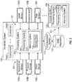
- FIG. 2 illustrates a monitored system 100 that is observed by a monitoring system 101 that includes a processing system 102 coupled to a sensor system 104.
- the sensor system 104 includes a plurality of sensors 106 that are configured to collect diagnostic and operational data related to the monitored system 100.
- the monitored system 100 can be any type of machine or system comprised of a plurality of components 108A-108N subject to detectable and predictable failure modes.
- the monitored system 100 can be an engine, a vehicle, a heating, ventilating, and air conditioning (HVAC) system, an elevator system, industrial machinery, or the like.
- HVAC heating, ventilating, and air conditioning
- embodiments are primarily described with respect to an engine system of an aircraft as the monitored system 100, such as the gas turbine engine 20 of FIG. 1 .
- the sensors 106 monitor a plurality of parameters of the monitored system 100, such as one or more temperature sensors 106A, pressure sensors 106B, strain gauges 106C, level sensors 106D, accelerometers 106E, rate sensors 106F, and the like.
- the processing system 102 can include processing circuitry 110 and a memory system 112 to store data and instructions that are executed by the processing circuitry 110.
- the executable instructions may be stored or organized in any manner and at any level of abstraction, such as in connection with a controlling and/or monitoring operation of the sensor system 104.
- the processing circuitry 110 can be any type or combination of central processing unit (CPU), including one or more of: a microprocessor, a digital signal processor (DSP), a microcontroller, an application specific integrated circuit (ASIC), a field programmable gate array (FPGA), or the like.
- the memory system 112 may include random access memory (RAM), read only memory (ROM), or other electronic, optical, magnetic, or any other computer readable medium onto which is stored data and algorithms in a non-transitory form.
- the processing system 102 is operable to access sensor data from the sensor system 104 and store values as sensed data 114 in the memory system 112.
- the processing system 102 can also interface with a communication system 118 to send and receive data values, such as sensed data 114, to a data repository 120.
- the processing system 102 can include other interfaces (not depicted), such as various outputs, wireless communication interfaces, and the like.
- the sensed data 114 can be snapshots or more densely populated data stream readings from the sensor system 104.
- the data repository 120 can be subdivided or distributed between multiple databases and/or locations.
- the data repository 120 is accessible by an analysis system 122.
- the combination of the data repository 120 and the analysis system 122 may be referred to as a distress detection system 121.
- the distress detection system 121 also includes one or more of the sensors 106 and may include the processing system 102.
- the analysis system 122 can be in close physical proximity to the monitored system 100 or may be remotely located at a greater distance.
- the analysis system 122 may also interface with a number of other instances of the data repository 120 associated with other instances of the monitored system 100 (e.g., a fleet of monitored systems 100).
- the analysis system 122 includes a processing system 130 with processing circuitry 132 and a memory system 134 operable to hold data and instructions executable by the processing circuitry 132.
- the processing system 130 is a workstation, a mainframe, a personal computer, a tablet computer, a mobile device, or other computing system configured as disclosed herein, while the processing system 102 may be an embedded computing system of the monitored system 100 operable to perform real-time data acquisition and analysis. Further, the processing system 130 can be distributed between multiple computing devices.
- the systems can include a lubrication system 302, a fuel combustion system 304, and other such systems (not depicted).
- the lubrication system 302 can include a lubrication circuit 306 operable to circulate a lubricant, such as oil, between a plurality of components.
- a pump 308 urges a lubricant flow 310 as a pressurized lubricant flow 312 to one or more components in need of lubrication, such as a gear system 314.
- the gear system 314 can be part of the geared architecture 48 of FIG.
- a return lubricant flow 316 from the gear system 314 can return lubricant to a tank (or sump) 318.
- Operation of the pump 308 can urge lubricant from the tank 318 through one or more other lubrication system components, such as a filter 320, in the lubrication flow 310.
- additional elements can be incorporated within the lubrication system 302, such as various sensors to detect temperature, pressure, level, debris, and the like.
- the fuel combustion system 304 can include at least one burner 322 of the combustor 56 of FIG. 1 . Fuel flow to the burner 322 and combustion within the burner 322 is substantially independent of the lubrication system 302. Thermal energy released by combustion of fuel in the burner 322 can impact rotational speed of components of the gas turbine engine 20 of FIG. 1 , such as low pressure turbine 46. Rotation of the low pressure turbine 46 can provide energy to rotate the pump 308 and/or gear system 314. However, fuel flow in the fuel combustion system 304 and lubricant flow in the lubrication system 302 are not directly linked and may be independently controlled. It will be understood that the fuel combustion system 304 can include additional elements beyond those depicted in FIG. 3 , such as a fuel pump, fuel tank, and various fuel related sensors.
- cross coupling of systems is observed through parameter fusion, where changes in parameter values in a system reflect effective changes in health of a cross-coupled system.
- Cross-coupled system effects may not be manifested in a single parameter.
- Evidence of deterioration of cross-coupled systems can become more apparent as multiple parameters are combined.
- a dependency matrix (D-matrix) can be utilized to account for the interaction between systems and fault propagation mechanisms.
- the D-matrix achieves this goal by performing dependency modeling in a discrete setting. This can be achieved by listing each sensor parameter of interest, isolating each failure as independent entities and then enumerating the likelihood of the failure being detected by the sensor system 104 of FIG. 2 .
- the D-matrix can be used to identify observable and unobservable failure modes based on available sensors 106 of the sensor system 104.
- Table 1 - D-Matrix for machine failure modes of mechanical and lubrication systems OilQ MOP MOT ODMR OilDP OilC Vibe Leak -1 -1 1 0 0 1 0 Spall 0 0 0 1 1 0 1 Seal Loss 0 0 0 1 1 0 GD 0 0 1 1 0 1 0 MOPSF 0 -1 0 1 0 0 1 HSD 0 -1 1 0 0 1 0 Coking -1 1 0 0 0 0 0 0 TC -1 -1 1 0 0 1 0 RD -1 -1 1 0 0 1 1 FPE -1 -1 1 1 1 1 1 1 1 1 1 1 1 1 1 1
- the D-matrix shown in Table 1 reflects common failure modes for mechanical and lubrication systems. Each row of Table 1 lists a failure type and each column indicates a measured parameter that may be used for failure detection. Failure types can include a leak, spall, seal loss, gear distress (GD), main oil pressure shaft failure (MOPSF), hot section distress (HSD), coking, tip clearance (TC), rotor distress (RD), and fuel pump efficiency (FPE). Examples of monitored parameters include oil quality (OilQ), main oil pressure (MOP), main oil temperature (MOT), oil debris monitor rate (ODMR), oil filter delta pressure (OilDP), and vibration (Vibe).
- GD main oil pressure shaft failure
- HSD hot section distress
- TC tip clearance
- RD rotor distress
- FPE fuel pump efficiency
- monitored parameters include oil quality (OilQ), main oil pressure (MOP), main oil temperature (MOT), oil debris monitor rate (ODMR), oil filter delta pressure (OilDP), and vibration (Vibe).
- a value of '-1' indicates there is a measurable system impact and the change is evident in a decrease in the value of the parameter as it relates to the specified failure mode.
- a value of '0' indicates that there is no known system impact therefore no measurable change will be observed by the parameter as it relates to the specified failure mode.
- a value of '1' indicates there is a measurable system impact and the measurable change is evident in an increase in the value of the parameter as it relates to the specified failure mode.
- Table 1 shows a subset of the failure modes specific to mechanical and lubrication systems, and a full D-matrix can include additional possible failure modes beyond those provided in this example.
- One or more failure modes of the D-matrix may exist outside of a typical lubrication system regime, such as 'burner distress', which although considered independent of the lubrication system, is shown to be observable by lubrication system parameters. This observation and subsequent system health assessment enables cross-coupled system parameters to be used to identify distress or degradation of the burner even though oil in the lubrication system is not consumed by the burner.
- the lubrication system performance can have observable interactions with other systems.
- thermal and pressure loading As oil absorbs more heat or is exposed to increasing loading, the properties change to accommodate the increased energy demand. This change can be indicated by the changes in temperature and pressure.
- a framework is described herein on which to confirm the expected interaction and to explore the possibility of taking advantage of these interactions by building the structure for fusion analysis of cross-coupled system interaction.
- the fusion approach can be used to replace and/or improve upon the viewpoint of a skilled analyst.
- a significant part of the effort for machine fusion logic is the conditioning required to establish the data for use after acquisition. While there are a number of possible parameters that can be considered, the examples herein are described with respect to main oil temperature and pressure.
- a design purpose of oil in a rotating machine is to reduce wear caused by friction and provide an effective heat transfer mechanism.
- Another critical function of the oil is to provide support to rotating components utilizing a hydrodynamic pressure gradient.
- the knowledge of a minimum operational oil quantity or a deleterious over quantity is critical in maintaining the health of the machine.
- An accurate measure of oil level is therefore a means of determining an acceptable oil quantity in the system; however, singularly measuring oil level/quantity does not guarantee that the oil is directed to the intended area(s).
- a reliable measure of oil pressure gives a clear indication of the ability of the system to work and can act as an indicator to failures that may not otherwise be detected.
- An example of the above mentioned failure type is a partially blocked tube; this scenario although not detectable by an oil level indication can become apparent by an increased Main Oil Pressure (MOP). This scenario can result in an increased pressure with a reduced flow capacity leading to reduced oil supply, hence increased wear.
- MOP Main Oil Pressure
- Oil pressure is typically measured using a differential pressure method; that is the measured reading is in reference to some other pressure source.
- the differential pressure can be synonymous to gauge pressure as the atmospheric pressure is the reference point.
- Measurement technologies span the gamut of modern sensing techniques.
- the measurement technology can be a piezo-resistive/piezoelectric device.
- a standard gauge pressure measurement can be obtained using conventional sensing equipment that is appropriately placed. The overall health of the system can then be correlated to the oil pressure reading. For pressure indicative failure modes, it is expected that as the system degrades, the pressure reading will indicate deterioration proportionally. A fielded system takes advantage of these levels of deterioration to declare maintenance directives. These directives or levels of alert can then be used to coordinate resources and asset allocation driven by safety and operationally efficiency. For example, a 'yellow' alert can be made to indicate a first level threshold crossing, to which is assigned a maximum duration of operation before servicing, while a 'Red' alert can be made to indicate impending failure and immediate halt to machine operation.
- MOP model Coeff i Speed ⁇ Coeff i + 1 OIT
- Equation 1 Application of the model represented by Equation 1 can reduce the data point scatter significantly. This model is useful in that it captures primary effects driven by main oil temperature and rotating speed of a shaft, such as the outer shaft 50 of FIG. 1 . By applying the model represented by Equation 1, data point scatter is reduced. With a model representing the dynamics of the system and effectively bounding the response range for specific speeds, advanced analytical diagnostic and prognostic approaches may be developed and applied.
- temperature measurement is an intuitive and ubiquitous metric used to determine the state of a system.
- a system in this context can range from the open atmosphere to complex close volume machines, such as gas turbines.
- the system component temperature of interest can be determined by the issue that is to be monitored.
- one of the main interests is the capability of the oil to transfer heat, provide lubrication and the dynamic support required for rotating structures.
- a sensing device that responds to changes in the temperature is used in this application. These devices are grouped under the banner commonly called thermometer. These devices often span a wide temperature range and employ a varied set of technologies.
- the oil operating temperature range is narrow when compared to the normal range of other systems, for instance, in the gas turbine engine 20 of FIG. 1 . This gives the opportunity to increase sensor resolution and hence increase the fidelity and observability of subtle changes in the system. This may be the most salient feature in providing further insight into the system dynamics. This feature can be utilized in helping to harness often overlooked indicators in the system.
- a functional monitoring system can use thresholds to confine operation within a safe operational range. Definition of enforceable limits on the oil operating temperature allows desirable tribological properties of the fluid to be maintained.
- Temperature limits can comprise of an upper and lower bound, and power dependent limits can be applied. Low oil temperature limits ensure that the oil viscosity is within the range of what is needed to lubricate or provide dynamic support. A high temperature level limit can indicate possible failure modes that include oil loss, lack of circulation due to variation in the pump capability or a blocked system.
- Failure modes of a temperature monitored system may not all experience a temperature limit excursion. Some failures can be exhibited as a transient perturbation of temperature - can be above or below the set limit - and dissipate with limited persistence. Other failures may be seen as a sustained low-level response well in the bounds of the upper or lower limit and within the sensor resolution. These indications are often overlooked as noise, or attributed to run to run variation.
- the viscosity of the oil can be related to nonlinear spring stiffness in a mechanical system.
- the nonlinear spring stiffness is sensitive to displacement
- the viscosity in a fluidic system is sensitive to the heat absorbed as indicated by changes in the oil temperature.
- a mechanical spring operates within an elastic domain. This elastic domain is defined as the displacement range proportional to the applied force that returns the spring to its original state when the force is removed.
- the mechanical spring is permanently deformed if the force applied extends the spring beyond the elastic domain into what is termed the plastic domain. This concept extends to the viscosity of the oil. Within the elastic regime, the oil returns to its useful state after doing work within the designed temperature range. Excursion beyond the set limit of the oil temperature induces the risk of irreversible deformation in the plastic regime with an early loss of functional properties of the oil.
- Embodiments operate within the limits of the elastic regime, where range variation of the oil can be used to determine changes in the system that in a traditional system might be overlooked as system variation. These observations can be utilized and combined with another parameter to detect otherwise imperceptible system deterioration.
- thermocouple type device can be utilized with voltage output proportional to the measured temperature.
- Approaches for temperature monitoring can include the application of high/low limits, speed/power dependent limits and slope trends or step shifts. These data points for a similar power setting can vary wildly.
- a legacy approach generally is not concerned about this variation but, as stated before, is primarily focused on the oil being within safe operating limits. Therefore, by establishing a limit line that corresponds to the elastic domain of the oil, there would be no flag set for such fluctuation. This is a limit of the legacy approach, the inability to harness the field of data to further probe into the workings of the machine.
- a correction factor can be applied to the oil temperature at a given shaft speed. This correction reduces the parameter variation and a running average defined by Equations 2 and 3 provides further smoothing of the parameter. A delta value can then be calculated between the smoothed, corrected data and the measured unprocessed data. Such processing may result in the clustering of data around speed ranges for some machines. This clustering reduces the intuitive application of trending patterns from visual observation and also is not ideal for applying fusion algorithms.
- a pump failure can be incipient due to worn bearings or seals.
- the failure can also be catastrophic due to a sheared shaft or broken bearing cage.
- An incipient failure may be a result of excessive component wear in the oil pump.
- a steady decrease in normalized pressure may be seen, which represents waning output efficiency of the pump.
- a catastrophic failure of the pump may appear as a step change observed in both the measured and delta data points.
- coking is the mechanism of forming a residue in the oil flow path when triggering conditions are met. Coking is an incipient process and, as a result, is evident in a gradual sustained increase in MOP.
- the oil temperature can enter into the plastic range, where the functional properties of the oil are irreversible changed.
- the flow of oil in the system can be hindered by varying degrees at different locations by a range of objects. For a blocked system, it is expected that the measured pressure will increase during operation and remain high after shut down for a longer time compared to a nominal engine.
- the variations can be in-range (below set failure mode detection limits) and within a run-to-run and machine-to-machine variation band. This can provide a unique challenge as the goal of 100% correct detection and 0% false alarms becomes more elusive.
- additional tools not used in traditional monitoring platforms can be used. Embodiments go beyond observing shifts in the trend of a parameter being measured but also align these measurements with other inputs and observations which to the nascent are independent. These relations can be difficult to capture and quantify with a conventional system and when ignored the next acknowledgment is the alert triggered by the electronic monitoring system, losing the opportunity for early detection.
- a data fusion system can take into account, in-range shifts, tribal knowledge, inferences and correlations to assess the likelihood of early system deterioration.
- FIG. 4 an example of a fuzzy logic structure 400 that may be implemented on the analysis system 122 of FIG. 2 is shown in greater detail.
- Fuzzy logic provides a way to arrive at a definite conclusion based upon vague, ambiguous, noisy or missing input information.
- the fuzzy logic approach may attempt to mimic a human logical approach to problem solving.
- a mathematical model is not required for control or diagnostics, but a heuristic application of a logical approach can be utilized.
- a complex system can therefore be assessed by applying observations and logical steps without the need of complex modeling. This implies that the level of fuzzy logic accuracy is dependent on the level of system understanding.
- the fuzzy structure 400 is divided into three sections, inputs 401, fuzzy reasoning rules 406, and defuzzification 408.
- the inputs 401 are numerical in nature and are the parameters of interest used in the assessment of the system condition.
- the inputs 401 are the main oil pressure delta 402 and main oil temperature delta 404.
- An independent variable, oil quantity, can also be considered but is not required if controlled for and consistent during analysis.
- the fuzzy reasoning rules 406 can evaluate the combined inputs 401 to determine an in-range interaction of the system of interest.
- the main oil pressure delta 402 and main oil temperature delta 404 are evaluated against IF statements reflecting conditions that determine system deterioration of a burner.
- the physics and dynamics of the system are captured at a high level that is coherent to human observation, intuition and physics.
- the results of the applied rules to the data are then evaluated to a set number that indicates a pre-determined condition of the system.
- preconditions for system state are set.
- the variation in the main oil pressure delta 402 and main oil temperature delta 404 when observed independently may not set alarms, particularly for a traditional approach, however when coupled, provides a clear indication that goes beyond machine-to-machine variations.
- the data suggested a leak as the oil temperature and pressure show deviation from the baseline.
- the expectation is an increase in temperature and a decrease in pressure.
- the leak progression indicator there is no indication of a progressive leak.
- an agent secondary to the oil system is responsible for the fluctuations observed in these indicators.
- There are a myriad of possible contributors to the systems results however by aligning observations from machines with an observed phenomenon to those without, a clear pattern emerges which strongly suggests a correlation between machine lubrication system distress and other systems.
- the method as shown can include the ability to detect an in-range fault by coupling (fusing) multiple indicators within operational range to determine the health of the system without intervention from a human observer.
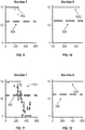
- Example results from eight different machines are depicted in FIGS. 5-12 .
- a limit line 500 is shown in FIGS. 5-12 as a horizontal broken line with an intercept at a number of fuzzy metric units to align a flag with failure observations.
- Observations of a first machine such as one instance of the gas turbine engine 20 of FIG. 1 are depicted as fuzzy metric data points 502 with respect to time in FIG. 5 .
- Observations of a second machine, such as another instance of the gas turbine engine 20 of FIG. 1 are depicted as fuzzy metric data points 602 with respect to time in FIG. 6 .
- the pattern continues with a third-eighth machines as fuzzy metric data points 702, 802, 902, 1002, 1102, and 1202 in FIGS. 7-12 .
- fuzzy metric and limits can provide an intuitive feel of a good component vs. a defective component.
- the fuzzy metric data points 602, 702, 802, and 1102 of FIGS. 6, 7, 8 , and 11 illustrate a clear excursion of the limit line 500 with a sustained below limit value. The effectiveness of the result can be validated against a known failure that is observable by these methods.
- the first and fifth machines of FIGS. 5 and 9 exhibit an early intermittent departure from the 'good' regime. Further, the first machine of FIG. 5 ran to a relative time of 600, while the fifth machine of FIG. 9 ran to relative time of 285 and was taken off line for repair of an unrelated component. Observation of the fifth machine of FIG. 9 indications suggest that the initial stages of component distress had initiated but was not allowed to propagate. The sixth machine of FIG. 10 and the eighth machine of FIG. 12 remained within the 'good' regime with no change over the running time of these machines. The second machine of FIG. 6 shows a precipitous fall in the fuzzy metric data points 602; however, an uptick in the indicator suggests that the component regained the 'good' state.
- FIG. 13 is a flow chart illustrating a method 1300 for distress detection, in accordance with an embodiment.
- the method 1300 may be performed, for example, by the analysis system 122 of FIG. 1 , which may be local to or remote from the monitored system 100 of FIG. 2 .
- a first parameter of a first system of the monitored system 100 is accessed from the data repository 120.
- the monitored system 100 can be, for instance, the gas turbine engine 20 of FIG. 1 .
- a second parameter of the first system of the monitored system 100 is accessed from the data repository 120.
- the first parameter and the second parameter can be derived from separate sensors 106 of the monitored system 100.
- the first parameter can be a main oil pressure
- the second parameter can be a main oil temperature or other such values.
- the analysis system 122 can apply fuzzy reasoning rules 406 to evaluate a combination of the first parameter and the second parameter to determine an in-range interaction with respect to a second system of the monitored system 100 as fuzzy metric data points 502-1202.
- the first system can be thermally cross-coupled to the second system absent a mechanical linkage, an electrical linkage, and a fluid linkage between the first system and the second system.
- the first system can be a lubrication system and the component of the second system can be a burner, for example.
- Observations of the first parameter and the second parameter can be constrained based on determining that the first parameter and the second parameter are both within a valid operating range.
- the first parameter and the second parameter may be normalized with respect to a third parameter, such as a level or speed indicator.
- the analysis system 122 can classify a component of the second system as being in distress based on comparing the fuzzy metric data points 502-1202 to a limit line 500.
- the analysis system 122 can assert a component distress indicator responsive to classifying the component of the second system as being in distress.
- a maintenance action can be triggered responsive to the component distress indicator being asserted.
- the maintenance action may modify operational parameters of the monitored system 100, such as constraining operating limits, requesting a shutdown, scheduling an inspection, or other such actions. Assertion of the component distress indicator may be prevented based on detection of a fault condition associated with the first system.
Landscapes
- Engineering & Computer Science (AREA)
- Physics & Mathematics (AREA)
- Theoretical Computer Science (AREA)
- Software Systems (AREA)
- Artificial Intelligence (AREA)
- Evolutionary Computation (AREA)
- General Physics & Mathematics (AREA)
- Mathematical Physics (AREA)
- Automation & Control Theory (AREA)
- General Engineering & Computer Science (AREA)
- Computational Linguistics (AREA)
- Data Mining & Analysis (AREA)
- Fuzzy Systems (AREA)
- Computing Systems (AREA)
- Mechanical Engineering (AREA)
- Testing And Monitoring For Control Systems (AREA)
- Testing Of Devices, Machine Parts, Or Other Structures Thereof (AREA)
Abstract
Description
- The subject matter disclosed herein generally relates to measurement systems and, more particularly, to a method and an apparatus for distress detection in dynamically and thermally coupled systems.
- Complex machines are composed of multiple systems that are intrinsically dependent. Health monitoring of complex machines typically focuses on systems or subsystems that are linked mechanically, electrically, or by a fluid. Cross coupling effects between systems of a machine can be difficult to accurately model, and thus health monitoring is typically partitioned into discrete blocks that map to particular systems or subsystems. For instance, parameters such as oil temperature and oil pressure may be used to determine a lubrication system health status; however, the impact of such parameters on other systems within a machine may not be readily apparent.
- According to one embodiment, a distress detection system includes a data repository operable to collect sensor data from a monitored system. The distress detection system also includes an analysis system with a processing system operable to access a first parameter of a first system of the monitored system from the data repository and access a second parameter of the first system of the monitored system from the data repository. The processing system is also operable to apply fuzzy reasoning rules to evaluate a combination of the first parameter and the second parameter to determine an in-range interaction with respect to a second system of the monitored system as fuzzy metric data points, classify a component of the second system as being in distress based on comparing the fuzzy metric data points to a limit line, and assert a component distress indicator responsive to classifying the component of the second system as being in distress.
- The first system may be thermally cross-coupled to the second system absent a mechanical linkage, an electrical linkage, and a fluid linkage between the first system and the second system.
- The monitored system may be a gas turbine engine.
- The first system may be a lubrication system and the component of the second system may be a burner.
- The first parameter may be a main oil pressure and the second parameter may be a main oil temperature.
- Observations of the first parameter and the second parameter may be constrained based on determining that the first parameter and the second parameter are both within a valid operating range.
- The first parameter and the second parameter may be normalized with respect to a third parameter.
- A maintenance action may be triggered responsive to the component distress indicator being asserted.
- Assertion of the component distress indicator may be prevented based on detection of a fault condition associated with the first system.
- The first parameter and the second parameter may be derived from separate sensors of the monitored system.
- According to another embodiment, a method of distress detection in a monitored system is provided. The method includes accessing, by an analysis system, a first parameter of a first system of the monitored system. The analysis system accesses a second parameter of the first system of the monitored system. Fuzzy reasoning rules are applied to evaluate a combination of the first parameter and the second parameter to determine an in-range interaction with respect to a second system of the monitored system as a plurality of fuzzy metric data points. A component of the second system is classified as being in distress based on comparing the fuzzy metric data points to a limit line. A component distress indicator is asserted responsive to classifying the component of the second system as being in distress.
- A technical effect of the apparatus, systems and methods is achieved by using data fusion and fuzzy logic to detect distress in dynamically and thermally coupled systems of the same machine as described herein.
- The following description should not be considered limiting. Certain embodiments of the disclosure will now be described, by way of example only, and with reference to the accompanying drawings, where like elements are numbered alike, in which:
-
FIG. 1 is a partial cross-sectional illustration of a gas turbine engine, in accordance with an embodiment of the disclosure; -
FIG. 2 is a block diagram of a monitored system, in accordance with an embodiment of the disclosure; -
FIG. 3 is a schematic illustration of systems of a gas turbine engine, in accordance with an embodiment of the disclosure; -
FIG. 4 is a block diagram of a fuzzy fusion structure, in accordance with an embodiment of the disclosure; -
FIG. 5 depicts an example of fusion results of a first machine, in accordance with embodiments of the disclosure; -
FIG. 6 depicts an example of fusion results of a second machine, in accordance with embodiments of the disclosure; -
FIG. 7 depicts an example of fusion results of a third machine, in accordance with embodiments of the disclosure; -
FIG. 8 depicts an example of fusion results of a fourth machine, in accordance with embodiments of the disclosure; -
FIG. 9 depicts an example of fusion results of a fifth machine, in accordance with embodiments of the disclosure; -
FIG. 10 depicts an example of fusion results of a sixth machine, in accordance with embodiments of the disclosure; -
FIG. 11 depicts an example of fusion results of a seventh machine, in accordance with embodiments of the disclosure; -
FIG. 12 depicts an example of fusion results of an eighth machine, in accordance with embodiments of the disclosure; and -
FIG. 13 is a flow chart illustrating a method, in accordance with an embodiment of the disclosure. - A detailed description of one or more embodiments of the disclosed apparatus and method are presented herein, by way of exemplification and not limitation, with reference to the Figures.
-
FIG. 1 schematically illustrates agas turbine engine 20. Thegas turbine engine 20 is disclosed herein as a two-spool turbofan that generally incorporates afan section 22, acompressor section 24, acombustor section 26 and aturbine section 28. Alternative engines might include an augmentor section (not shown) among other systems or features. Thefan section 22 drives air along a bypass flow path B in a bypass duct, while thecompressor section 24 drives air along a core flow path C for compression and communication into thecombustor section 26 then expansion through theturbine section 28. Although depicted as a two-spool turbofan gas turbine engine in the disclosed non-limiting embodiment, it should be understood that the concepts described herein are not limited to use with two-spool turbofans as the teachings may be applied to other types of turbine engines including three-spool architectures. - The
exemplary engine 20 generally includes alow speed spool 30 and ahigh speed spool 32 mounted for rotation about an engine central longitudinal axis A relative to an enginestatic structure 36 viaseveral bearing systems 38. It should be understood thatvarious bearing systems 38 at various locations may alternatively or additionally be provided, and the location ofbearing systems 38 may be varied as appropriate to the application. - The
low speed spool 30 generally includes aninner shaft 40 that interconnects afan 42, alow pressure compressor 44 and alow pressure turbine 46. Theinner shaft 40 is connected to thefan 42 through a speed change mechanism, which in exemplarygas turbine engine 20 is illustrated as a gearedarchitecture 48 to drive thefan 42 at a lower speed than thelow speed spool 30. Thehigh speed spool 32 includes anouter shaft 50 that interconnects ahigh pressure compressor 52 andhigh pressure turbine 54. Acombustor 56 is arranged inexemplary gas turbine 20 between thehigh pressure compressor 52 and thehigh pressure turbine 54. An enginestatic structure 36 is arranged generally between thehigh pressure turbine 54 and thelow pressure turbine 46. The enginestatic structure 36 further supports bearingsystems 38 in theturbine section 28. Theinner shaft 40 and theouter shaft 50 are concentric and rotate viabearing systems 38 about the engine central longitudinal axis A which is collinear with their longitudinal axes. - The core airflow is compressed by the
low pressure compressor 44 then thehigh pressure compressor 52, mixed and burned with fuel in thecombustor 56, then expanded over thehigh pressure turbine 54 andlow pressure turbine 46. Theturbines low speed spool 30 andhigh speed spool 32 in response to the expansion. It will be appreciated that each of the positions of thefan section 22,compressor section 24,combustor section 26,turbine section 28, and fandrive gear system 48 may be varied. For example,gear system 48 may be located aft ofcombustor section 26 or even aft ofturbine section 28, andfan section 22 may be positioned forward or aft of the location ofgear system 48. - The
engine 20 in one example is a high-bypass geared aircraft engine. In a further example, theengine 20 bypass ratio is greater than about six (6), with an example embodiment being greater than about ten (10), the gearedarchitecture 48 is an epicyclic gear train, such as a planetary gear system or other gear system, with a gear reduction ratio of greater than about 2.3 and thelow pressure turbine 46 has a pressure ratio that is greater than about five. In one disclosed embodiment, theengine 20 bypass ratio is greater than about ten (10:1), the fan diameter is significantly larger than that of thelow pressure compressor 44, and thelow pressure turbine 46 has a pressure ratio that is greater than about five 5:1.Low pressure turbine 46 pressure ratio is pressure measured prior to inlet oflow pressure turbine 46 as related to the pressure at the outlet of thelow pressure turbine 46 prior to an exhaust nozzle. The gearedarchitecture 48 may be an epicycle gear train, such as a planetary gear system or other gear system, with a gear reduction ratio of greater than about 2.3:1. It should be understood, however, that the above parameters are only exemplary of one embodiment of a geared architecture engine and that the present disclosure is applicable to other gas turbine engines including direct drive turbofans. - A significant amount of thrust is provided by the bypass flow B due to the high bypass ratio. The
fan section 22 of theengine 20 is designed for a particular flight condition; typically cruise at about 0.8 Mach and about 35,000 feet (10,688 meters). The flight condition of 0.8 Mach and 35,000 ft (10,688 meters), with the engine at its best fuel consumption, also known as "bucket cruise Thrust Specific Fuel Consumption ('TSFC')", is the industry standard parameter of lbm of fuel being burned divided by lbf of thrust the engine produces at that minimum point. "Low fan pressure ratio" is the pressure ratio across the fan blade alone, without a Fan Exit Guide Vane ("FEGV") system. The low fan pressure ratio as disclosed herein according to one non-limiting embodiment is less than about 1.45. "Low corrected fan tip speed" is the actual fan tip speed in ft/sec divided by an industry standard temperature correction of [(Tram °R)/(518.7 °R)]0.5 ([(Tram °K)/(288.2 °K)]0.5). The "Low corrected fan tip speed" as disclosed herein according to one non-limiting embodiment is less than about 1150 ft/second (350.5 m/sec). - The
gas turbine engine 20 is one type of complex machine that includes multiple systems with physical interactions between the systems. Embodiments use parameters that are measured in one system to determine the diagnostic state of another coupled system with no or limited system observability. A fuzzy logic fusion approach can be used to identify deterioration of one system based upon the parameters of one or more other systems within the machine. For example, systems that do not share a mechanical linkage, an electrical linkage, or a fluid linkage may be thermally coupled within a machine. In systems with reduced observability, detection of distress or degraded operation of a system may be determined through data fusion of two or more parameters of a different system and observation of changes while the parameters are still considered to be within acceptable operating ranges. The approaches disclosed herein are not limited to gas turbine engines and may be applied to a variety of monitored systems as further described in reference toFIG. 2 . - Referring now to the drawings,
FIG. 2 illustrates a monitoredsystem 100 that is observed by amonitoring system 101 that includes aprocessing system 102 coupled to asensor system 104. Thesensor system 104 includes a plurality of sensors 106 that are configured to collect diagnostic and operational data related to the monitoredsystem 100. The monitoredsystem 100 can be any type of machine or system comprised of a plurality ofcomponents 108A-108N subject to detectable and predictable failure modes. For example, the monitoredsystem 100 can be an engine, a vehicle, a heating, ventilating, and air conditioning (HVAC) system, an elevator system, industrial machinery, or the like. For purposes of explanation, embodiments are primarily described with respect to an engine system of an aircraft as the monitoredsystem 100, such as thegas turbine engine 20 ofFIG. 1 . In the example ofFIG. 2 , the sensors 106 monitor a plurality of parameters of the monitoredsystem 100, such as one ormore temperature sensors 106A,pressure sensors 106B, strain gauges 106C,level sensors 106D, accelerometers 106E,rate sensors 106F, and the like. - The
processing system 102 can includeprocessing circuitry 110 and amemory system 112 to store data and instructions that are executed by theprocessing circuitry 110. The executable instructions may be stored or organized in any manner and at any level of abstraction, such as in connection with a controlling and/or monitoring operation of thesensor system 104. Theprocessing circuitry 110 can be any type or combination of central processing unit (CPU), including one or more of: a microprocessor, a digital signal processor (DSP), a microcontroller, an application specific integrated circuit (ASIC), a field programmable gate array (FPGA), or the like. Also, in embodiments, thememory system 112 may include random access memory (RAM), read only memory (ROM), or other electronic, optical, magnetic, or any other computer readable medium onto which is stored data and algorithms in a non-transitory form. Theprocessing system 102 is operable to access sensor data from thesensor system 104 and store values as senseddata 114 in thememory system 112. Theprocessing system 102 can also interface with acommunication system 118 to send and receive data values, such as senseddata 114, to adata repository 120. Theprocessing system 102 can include other interfaces (not depicted), such as various outputs, wireless communication interfaces, and the like. The senseddata 114 can be snapshots or more densely populated data stream readings from thesensor system 104. - The
data repository 120 can be subdivided or distributed between multiple databases and/or locations. In embodiments, thedata repository 120 is accessible by ananalysis system 122. The combination of thedata repository 120 and theanalysis system 122 may be referred to as adistress detection system 121. In some embodiments, thedistress detection system 121 also includes one or more of the sensors 106 and may include theprocessing system 102. Theanalysis system 122 can be in close physical proximity to the monitoredsystem 100 or may be remotely located at a greater distance. Theanalysis system 122 may also interface with a number of other instances of thedata repository 120 associated with other instances of the monitored system 100 (e.g., a fleet of monitored systems 100). Similar to themonitoring system 101, theanalysis system 122 includes aprocessing system 130 withprocessing circuitry 132 and amemory system 134 operable to hold data and instructions executable by theprocessing circuitry 132. In some embodiments, theprocessing system 130 is a workstation, a mainframe, a personal computer, a tablet computer, a mobile device, or other computing system configured as disclosed herein, while theprocessing system 102 may be an embedded computing system of the monitoredsystem 100 operable to perform real-time data acquisition and analysis. Further, theprocessing system 130 can be distributed between multiple computing devices. - Referring now to
FIG. 3 , a plurality of systems of thegas turbine engine 20 ofFIG. 1 are depicted schematically. In the example ofFIG. 3 , the systems can include alubrication system 302, afuel combustion system 304, and other such systems (not depicted). Thelubrication system 302 can include alubrication circuit 306 operable to circulate a lubricant, such as oil, between a plurality of components. In the example ofFIG. 3 , apump 308 urges alubricant flow 310 as apressurized lubricant flow 312 to one or more components in need of lubrication, such as agear system 314. Thegear system 314 can be part of the gearedarchitecture 48 ofFIG. 1 , part of a gearbox (not depicted), or other such rotatable components or accessories of thegas turbine engine 20 ofFIG. 1 . Areturn lubricant flow 316 from thegear system 314 can return lubricant to a tank (or sump) 318. Operation of thepump 308 can urge lubricant from thetank 318 through one or more other lubrication system components, such as afilter 320, in thelubrication flow 310. It will be understood that additional elements can be incorporated within thelubrication system 302, such as various sensors to detect temperature, pressure, level, debris, and the like. - The
fuel combustion system 304 can include at least oneburner 322 of thecombustor 56 ofFIG. 1 . Fuel flow to theburner 322 and combustion within theburner 322 is substantially independent of thelubrication system 302. Thermal energy released by combustion of fuel in theburner 322 can impact rotational speed of components of thegas turbine engine 20 ofFIG. 1 , such aslow pressure turbine 46. Rotation of thelow pressure turbine 46 can provide energy to rotate thepump 308 and/orgear system 314. However, fuel flow in thefuel combustion system 304 and lubricant flow in thelubrication system 302 are not directly linked and may be independently controlled. It will be understood that thefuel combustion system 304 can include additional elements beyond those depicted inFIG. 3 , such as a fuel pump, fuel tank, and various fuel related sensors. - In embodiments, cross coupling of systems is observed through parameter fusion, where changes in parameter values in a system reflect effective changes in health of a cross-coupled system. Cross-coupled system effects may not be manifested in a single parameter. Evidence of deterioration of cross-coupled systems can become more apparent as multiple parameters are combined. As one example, a dependency matrix (D-matrix) can be utilized to account for the interaction between systems and fault propagation mechanisms. The D-matrix achieves this goal by performing dependency modeling in a discrete setting. This can be achieved by listing each sensor parameter of interest, isolating each failure as independent entities and then enumerating the likelihood of the failure being detected by the
sensor system 104 ofFIG. 2 . The D-matrix can be used to identify observable and unobservable failure modes based on available sensors 106 of thesensor system 104.Table 1 - D-Matrix for machine failure modes of mechanical and lubrication systems OilQ MOP MOT ODMR OilDP OilC Vibe Leak -1 -1 1 0 0 1 0 Spall 0 0 0 1 1 0 1 Seal Loss 0 0 0 1 1 0 0 GD 0 0 1 1 0 1 0 MOPSF 0 -1 0 1 0 0 1 HSD 0 -1 1 0 0 1 0 Coking -1 1 0 0 0 0 0 TC -1 -1 1 0 0 1 0 RD -1 -1 1 0 0 1 1 FPE -1 -1 1 1 1 1 1 - The D-matrix shown in Table 1 reflects common failure modes for mechanical and lubrication systems. Each row of Table 1 lists a failure type and each column indicates a measured parameter that may be used for failure detection. Failure types can include a leak, spall, seal loss, gear distress (GD), main oil pressure shaft failure (MOPSF), hot section distress (HSD), coking, tip clearance (TC), rotor distress (RD), and fuel pump efficiency (FPE). Examples of monitored parameters include oil quality (OilQ), main oil pressure (MOP), main oil temperature (MOT), oil debris monitor rate (ODMR), oil filter delta pressure (OilDP), and vibration (Vibe). In the example of Table 1, a value of '-1' indicates there is a measurable system impact and the change is evident in a decrease in the value of the parameter as it relates to the specified failure mode. A value of '0' indicates that there is no known system impact therefore no measurable change will be observed by the parameter as it relates to the specified failure mode. A value of '1' indicates there is a measurable system impact and the measurable change is evident in an increase in the value of the parameter as it relates to the specified failure mode. A good practice for diagnostics, prognostics and health management system design is to begin by identifying possible failure modes. These modes are presented in a D-matrix format as illustrated in Table 1. Table 1 shows a subset of the failure modes specific to mechanical and lubrication systems, and a full D-matrix can include additional possible failure modes beyond those provided in this example. One or more failure modes of the D-matrix may exist outside of a typical lubrication system regime, such as 'burner distress', which although considered independent of the lubrication system, is shown to be observable by lubrication system parameters. This observation and subsequent system health assessment enables cross-coupled system parameters to be used to identify distress or degradation of the burner even though oil in the lubrication system is not consumed by the burner.
- Although not directly connected mechanically or by a shared fluid, the lubrication system performance can have observable interactions with other systems. The main impact to lubrication properties of interest, e.g., pressure and temperature of the oil, is thermal and pressure loading. As oil absorbs more heat or is exposed to increasing loading, the properties change to accommodate the increased energy demand. This change can be indicated by the changes in temperature and pressure. Consider a closed lubrication system that has a detectable leak. It would be expected that as oil is lost, the system pressure is reduced and an increase in temperature would be observed as the heat exchange demand remains constant but the viscosity index of the oil is reduced. For any system that interacts with the lubrication system, it is possible or likely that additional heat load will be captured by the oil, prompting an increase in temperature and a change in oil viscosity and dynamics that would directly impact the measured oil pressure.
- A framework is described herein on which to confirm the expected interaction and to explore the possibility of taking advantage of these interactions by building the structure for fusion analysis of cross-coupled system interaction. The fusion approach can be used to replace and/or improve upon the viewpoint of a skilled analyst. However, unlike a human observer who is advantaged by pre-conditioned inputs and inferences, a significant part of the effort for machine fusion logic is the conditioning required to establish the data for use after acquisition. While there are a number of possible parameters that can be considered, the examples herein are described with respect to main oil temperature and pressure.
- A design purpose of oil in a rotating machine is to reduce wear caused by friction and provide an effective heat transfer mechanism. Another critical function of the oil is to provide support to rotating components utilizing a hydrodynamic pressure gradient. The knowledge of a minimum operational oil quantity or a deleterious over quantity is critical in maintaining the health of the machine. An accurate measure of oil level is therefore a means of determining an acceptable oil quantity in the system; however, singularly measuring oil level/quantity does not guarantee that the oil is directed to the intended area(s). A reliable measure of oil pressure gives a clear indication of the ability of the system to work and can act as an indicator to failures that may not otherwise be detected. An example of the above mentioned failure type is a partially blocked tube; this scenario although not detectable by an oil level indication can become apparent by an increased Main Oil Pressure (MOP). This scenario can result in an increased pressure with a reduced flow capacity leading to reduced oil supply, hence increased wear.
- Oil pressure is typically measured using a differential pressure method; that is the measured reading is in reference to some other pressure source. For example, the differential pressure can be synonymous to gauge pressure as the atmospheric pressure is the reference point. Measurement technologies span the gamut of modern sensing techniques. As one example, the measurement technology can be a piezo-resistive/piezoelectric device.
- A standard gauge pressure measurement can be obtained using conventional sensing equipment that is appropriately placed. The overall health of the system can then be correlated to the oil pressure reading. For pressure indicative failure modes, it is expected that as the system degrades, the pressure reading will indicate deterioration proportionally. A fielded system takes advantage of these levels of deterioration to declare maintenance directives. These directives or levels of alert can then be used to coordinate resources and asset allocation driven by safety and operationally efficiency. For example, a 'yellow' alert can be made to indicate a first level threshold crossing, to which is assigned a maximum duration of operation before servicing, while a 'Red' alert can be made to indicate impending failure and immediate halt to machine operation.
- With the advent of advanced data acquisition and storage systems, patterns and trends, previously fleeting are now accessible, retrievable and available for advanced data processing algorithms to be applied. These advancements however cannot replace the venerable method of "knowing" the machine, its related dynamics, identifying the highest likely failure possibilities, and then delineating the mechanism of likely paths to failure. There is a wide band of pressure values over the speed range of interest. Wide variation in readings reduces the effectiveness of the MOP raw readings for monitoring purposes and can lead to false alarms.
- An empirical model - derived from test data regression - of the form shown by
Equation 1, can predict the oil pressure as a function of rotating speed and oil temperature.
- Application of the model represented by
Equation 1 can reduce the data point scatter significantly. This model is useful in that it captures primary effects driven by main oil temperature and rotating speed of a shaft, such as theouter shaft 50 ofFIG. 1 . By applying the model represented byEquation 1, data point scatter is reduced. With a model representing the dynamics of the system and effectively bounding the response range for specific speeds, advanced analytical diagnostic and prognostic approaches may be developed and applied. - Applying an appropriate model over the operating speed range significantly reduces the data point scatter and can be effective in predicting oil pressure within known constraints. By calculating and tracking the delta between predicted and measured pressure, incipient faults can be identified earlier and emerging catastrophic events identified with higher confidence.
- As a further example, temperature measurement is an intuitive and ubiquitous metric used to determine the state of a system. A system in this context can range from the open atmosphere to complex close volume machines, such as gas turbines. The system component temperature of interest can be determined by the issue that is to be monitored. In the case of a gas turbine, one of the main interests is the capability of the oil to transfer heat, provide lubrication and the dynamic support required for rotating structures. A sensing device that responds to changes in the temperature is used in this application. These devices are grouped under the banner commonly called thermometer. These devices often span a wide temperature range and employ a varied set of technologies. The oil operating temperature range is narrow when compared to the normal range of other systems, for instance, in the
gas turbine engine 20 ofFIG. 1 . This gives the opportunity to increase sensor resolution and hence increase the fidelity and observability of subtle changes in the system. This may be the most salient feature in providing further insight into the system dynamics. This feature can be utilized in helping to harness often overlooked indicators in the system. - As with development of pressure monitoring capability, further development of temperature data manipulation can provide the capability to identify system specific changes. A functional monitoring system can use thresholds to confine operation within a safe operational range. Definition of enforceable limits on the oil operating temperature allows desirable tribological properties of the fluid to be maintained.
- Temperature limits can comprise of an upper and lower bound, and power dependent limits can be applied. Low oil temperature limits ensure that the oil viscosity is within the range of what is needed to lubricate or provide dynamic support. A high temperature level limit can indicate possible failure modes that include oil loss, lack of circulation due to variation in the pump capability or a blocked system.
- Failure modes of a temperature monitored system may not all experience a temperature limit excursion. Some failures can be exhibited as a transient perturbation of temperature - can be above or below the set limit - and dissipate with limited persistence. Other failures may be seen as a sustained low-level response well in the bounds of the upper or lower limit and within the sensor resolution. These indications are often overlooked as noise, or attributed to run to run variation.
- For convenience, the viscosity of the oil can be related to nonlinear spring stiffness in a mechanical system. Where as in the mechanical system the nonlinear spring stiffness is sensitive to displacement, the viscosity in a fluidic system is sensitive to the heat absorbed as indicated by changes in the oil temperature. A mechanical spring operates within an elastic domain. This elastic domain is defined as the displacement range proportional to the applied force that returns the spring to its original state when the force is removed.
- The mechanical spring is permanently deformed if the force applied extends the spring beyond the elastic domain into what is termed the plastic domain. This concept extends to the viscosity of the oil. Within the elastic regime, the oil returns to its useful state after doing work within the designed temperature range. Excursion beyond the set limit of the oil temperature induces the risk of irreversible deformation in the plastic regime with an early loss of functional properties of the oil.
- Embodiments operate within the limits of the elastic regime, where range variation of the oil can be used to determine changes in the system that in a traditional system might be overlooked as system variation. These observations can be utilized and combined with another parameter to detect otherwise imperceptible system deterioration.
- A thermocouple type device can be utilized with voltage output proportional to the measured temperature. Approaches for temperature monitoring can include the application of high/low limits, speed/power dependent limits and slope trends or step shifts. These data points for a similar power setting can vary wildly. A legacy approach generally is not concerned about this variation but, as stated before, is primarily focused on the oil being within safe operating limits. Therefore, by establishing a limit line that corresponds to the elastic domain of the oil, there would be no flag set for such fluctuation. This is a limit of the legacy approach, the inability to harness the field of data to further probe into the workings of the machine.
- To improve the capability to isolate in-range faults and subtle trends, a correction factor can be applied to the oil temperature at a given shaft speed. This correction reduces the parameter variation and a running average defined by
Equations 

- The envelope of operation should be understood in its entirety, as operational 'pinch' points can exist where the system response is strongly influenced by factors outside of the system being measured and requires appropriately adjusted limits.
- Component failures are often thought to be incipient by nature hence trendable and once initiated predictable; however, many failures are sudden and catastrophic while others exhibit failure transient parameter change that are insignificant compared to a set limit line.
- A pump failure can be incipient due to worn bearings or seals. The failure can also be catastrophic due to a sheared shaft or broken bearing cage. An incipient failure may be a result of excessive component wear in the oil pump. A steady decrease in normalized pressure may be seen, which represents waning output efficiency of the pump. In some instances a catastrophic failure of the pump may appear as a step change observed in both the measured and delta data points.
- As a further consideration, coking is the mechanism of forming a residue in the oil flow path when triggering conditions are met. Coking is an incipient process and, as a result, is evident in a gradual sustained increase in MOP. The oil temperature can enter into the plastic range, where the functional properties of the oil are irreversible changed.
- The flow of oil in the system can be hindered by varying degrees at different locations by a range of objects. For a blocked system, it is expected that the measured pressure will increase during operation and remain high after shut down for a longer time compared to a nominal engine.
- There may be subtle variations in the monitored parameters during a failure mode of interest. The variations can be in-range (below set failure mode detection limits) and within a run-to-run and machine-to-machine variation band. This can provide a unique challenge as the goal of 100% correct detection and 0% false alarms becomes more elusive. To improve the metrics, additional tools not used in traditional monitoring platforms can be used. Embodiments go beyond observing shifts in the trend of a parameter being measured but also align these measurements with other inputs and observations which to the nascent are independent. These relations can be difficult to capture and quantify with a conventional system and when ignored the next acknowledgment is the alert triggered by the electronic monitoring system, losing the opportunity for early detection.
- In embodiments, a data fusion system can take into account, in-range shifts, tribal knowledge, inferences and correlations to assess the likelihood of early system deterioration. Referring now to
FIG. 4 , an example of afuzzy logic structure 400 that may be implemented on theanalysis system 122 ofFIG. 2 is shown in greater detail. Fuzzy logic provides a way to arrive at a definite conclusion based upon vague, ambiguous, noisy or missing input information. The fuzzy logic approach may attempt to mimic a human logical approach to problem solving. A mathematical model is not required for control or diagnostics, but a heuristic application of a logical approach can be utilized. A complex system can therefore be assessed by applying observations and logical steps without the need of complex modeling. This implies that the level of fuzzy logic accuracy is dependent on the level of system understanding. - The
fuzzy structure 400 is divided into three sections,inputs 401,fuzzy reasoning rules 406, anddefuzzification 408. Theinputs 401 are numerical in nature and are the parameters of interest used in the assessment of the system condition. For this example, theinputs 401 are the mainoil pressure delta 402 and mainoil temperature delta 404. An independent variable, oil quantity, can also be considered but is not required if controlled for and consistent during analysis. - The
fuzzy reasoning rules 406 can evaluate the combinedinputs 401 to determine an in-range interaction of the system of interest. In this example, the mainoil pressure delta 402 and mainoil temperature delta 404 are evaluated against IF statements reflecting conditions that determine system deterioration of a burner. Here, the physics and dynamics of the system are captured at a high level that is coherent to human observation, intuition and physics. - The results of the applied rules to the data are then evaluated to a set number that indicates a pre-determined condition of the system. Here, preconditions for system state are set. In the case of system deterioration, there are numerical limits that align with physical observation. For example, for a part that is failing it is important to set an indicator that shows the difference between "good", "nominal", and "bad" in
defuzzification 408. By understanding the dynamics of the system as related to fault progression and condition indicators the system performance indicators will highlight incipient issues even as the degradation occurs within the active parameter's 'healthy' range. - The variation in the main
oil pressure delta 402 and mainoil temperature delta 404 when observed independently may not set alarms, particularly for a traditional approach, however when coupled, provides a clear indication that goes beyond machine-to-machine variations. Initially, the data suggested a leak as the oil temperature and pressure show deviation from the baseline. As previously mentioned, for a leak, the expectation is an increase in temperature and a decrease in pressure. By looking at the leak progression indicator there is no indication of a progressive leak. This observation then suggests that an agent secondary to the oil system is responsible for the fluctuations observed in these indicators. There are a myriad of possible contributors to the systems results, however by aligning observations from machines with an observed phenomenon to those without, a clear pattern emerges which strongly suggests a correlation between machine lubrication system distress and other systems. - The method as shown can include the ability to detect an in-range fault by coupling (fusing) multiple indicators within operational range to determine the health of the system without intervention from a human observer.
- Example results from eight different machines are depicted in
FIGS. 5-12 . Alimit line 500 is shown inFIGS. 5-12 as a horizontal broken line with an intercept at a number of fuzzy metric units to align a flag with failure observations. Observations of a first machine, such as one instance of thegas turbine engine 20 ofFIG. 1 are depicted as fuzzymetric data points 502 with respect to time inFIG. 5 . Observations of a second machine, such as another instance of thegas turbine engine 20 ofFIG. 1 are depicted as fuzzymetric data points 602 with respect to time inFIG. 6 . The pattern continues with a third-eighth machines as fuzzymetric data points FIGS. 7-12 . Choosing the fuzzy metric and limits as shown can provide an intuitive feel of a good component vs. a defective component. For instance, the fuzzymetric data points FIGS. 6, 7, 8 , and11 illustrate a clear excursion of thelimit line 500 with a sustained below limit value. The effectiveness of the result can be validated against a known failure that is observable by these methods. - The first and fifth machines of
FIGS. 5 and9 exhibit an early intermittent departure from the 'good' regime. Further, the first machine ofFIG. 5 ran to a relative time of 600, while the fifth machine ofFIG. 9 ran to relative time of 285 and was taken off line for repair of an unrelated component. Observation of the fifth machine ofFIG. 9 indications suggest that the initial stages of component distress had initiated but was not allowed to propagate. The sixth machine ofFIG. 10 and the eighth machine ofFIG. 12 remained within the 'good' regime with no change over the running time of these machines. The second machine ofFIG. 6 shows a precipitous fall in the fuzzymetric data points 602; however, an uptick in the indicator suggests that the component regained the 'good' state. This could be a result of the component being replaced or a change in running condition not reflected in the data set. Similar fluctuations in the fuzzy metric are observed and could also suggest that further tuning may be needed or account taken for inventory of the component change or run condition. When the component of interest is observed for the machines with a clear limit excursion with appreciable persistence i.e., 2nd, 3rd, 4th, and 7th machines ofFIGS. 6, 7, 8 , and11 , there is clear alignment between the limit flag being set and a defective component. The same is also true for machines without the defect limit excursion below thelimit line 500, the component of interest is deemed good. These results show no misdetection, no false alarms and correct detection. This suggests that detecting a critical fault by fusing parameters initially deemed independent of another system with parameters that are well within the acceptable range of healthy indication can provide a useful detection of system distress before a failure actually occurs. - Referring now to
FIG. 13 with continued reference toFIGS. 1-12 ,FIG. 13 is a flow chart illustrating amethod 1300 for distress detection, in accordance with an embodiment. Themethod 1300 may be performed, for example, by theanalysis system 122 ofFIG. 1 , which may be local to or remote from the monitoredsystem 100 ofFIG. 2 . Atblock 1302, a first parameter of a first system of the monitoredsystem 100 is accessed from thedata repository 120. The monitoredsystem 100 can be, for instance, thegas turbine engine 20 ofFIG. 1 . - At
block 1304, a second parameter of the first system of the monitoredsystem 100 is accessed from thedata repository 120. The first parameter and the second parameter can be derived from separate sensors 106 of the monitoredsystem 100. As one example, the first parameter can be a main oil pressure, and the second parameter can be a main oil temperature or other such values. - At
block 1306, theanalysis system 122 can applyfuzzy reasoning rules 406 to evaluate a combination of the first parameter and the second parameter to determine an in-range interaction with respect to a second system of the monitoredsystem 100 as fuzzy metric data points 502-1202. The first system can be thermally cross-coupled to the second system absent a mechanical linkage, an electrical linkage, and a fluid linkage between the first system and the second system. The first system can be a lubrication system and the component of the second system can be a burner, for example. Observations of the first parameter and the second parameter can be constrained based on determining that the first parameter and the second parameter are both within a valid operating range. The first parameter and the second parameter may be normalized with respect to a third parameter, such as a level or speed indicator. - At
block 1308, theanalysis system 122 can classify a component of the second system as being in distress based on comparing the fuzzy metric data points 502-1202 to alimit line 500. Atblock 1310, theanalysis system 122 can assert a component distress indicator responsive to classifying the component of the second system as being in distress. A maintenance action can be triggered responsive to the component distress indicator being asserted. The maintenance action may modify operational parameters of the monitoredsystem 100, such as constraining operating limits, requesting a shutdown, scheduling an inspection, or other such actions. Assertion of the component distress indicator may be prevented based on detection of a fault condition associated with the first system. - While the above description has described the flow process of
FIG. 13 in a particular order, it should be appreciated that unless otherwise specifically required in the attached claims that the ordering of the steps may be varied. - The term "about" is intended to include the degree of error associated with measurement of the particular quantity based upon the equipment available at the time of filing the application.
- The terminology used herein is for the purpose of describing particular embodiments only and is not intended to be limiting of the present disclosure. As used herein, the singular forms "a", "an" and "the" are intended to include the plural forms as well, unless the context clearly indicates otherwise. It will be further understood that the terms "comprises" and/or "comprising," when used in this specification, specify the presence of stated features, integers, steps, operations, elements, and/or components, but do not preclude the presence or addition of one or more other features, integers, steps, operations, element components, and/or groups thereof.
- While the present disclosure has been described with reference to an exemplary embodiment or embodiments, it will be understood by those skilled in the art that various changes may be made and equivalents may be substituted for elements thereof without departing from the scope of the present disclosure. In addition, many modifications may be made to adapt a particular situation or material to the teachings of the present disclosure without departing from the essential scope thereof. Therefore, it is intended that the present disclosure not be limited to the particular embodiment disclosed as the best mode contemplated for carrying out this present disclosure, but that the present disclosure will include all embodiments falling within the scope of the claims.
Claims (15)
- A distress detection system (121) comprising:a data repository (120) operable to collect a plurality of sensor data from a monitored system (100); andan analysis system (122) comprising a processing system (130) operable to:access a first parameter of a first system of the monitored system from the data repository;access a second parameter of the first system of the monitored system from the data repository;apply a plurality of fuzzy reasoning rules to evaluate a combination of the first parameter and the second parameter to determine an in-range interaction with respect to a second system of the monitored system as a plurality of fuzzy metric data points;classify a component of the second system as being in distress based on comparing the fuzzy metric data points to a limit line; andassert a component distress indicator responsive to classifying the component of the second system as being in distress.
- The distress detection system of claim 1, wherein the first system is thermally cross-coupled to the second system absent a mechanical linkage, an electrical linkage, and a fluid linkage between the first system and the second system.
- The distress detection system of claim 2, wherein the monitored system is a gas turbine engine (20), preferably wherein the first system is a lubrication system (302) and the component of the second system is a burner (322), further preferably wherein the first parameter is a main oil pressure and the second parameter is a main oil temperature.
- The distress detection system of any preceding claim, wherein observations of the first parameter and the second parameter are constrained based on determining that the first parameter and the second parameter are both within a valid operating range.
- The distress detection system of any preceding claim, wherein the first parameter and the second parameter are normalized with respect to a third parameter.
- The distress detection system of any preceding claim, wherein a maintenance action is triggered responsive to the component distress indicator being asserted.
- The distress detection system of any preceding claim, wherein assertion of the component distress indicator is prevented based on detection of a fault condition associated with the first system.
- The distress detection system of any preceding claim, wherein the first parameter and the second parameter are derived from separate sensors (106 A-F) of the monitored system.
- A method (1300) of distress detection in a monitored system (100), the method comprising:accessing (1302), by an analysis system (122), a first parameter of a first system of the monitored system;accessing (1304), by the analysis system (122), a second parameter of the first system of the monitored system;applying (1306) a plurality of fuzzy reasoning rules to evaluate a combination of the first parameter and the second parameter to determine an in-range interaction with respect to a second system of the monitored system as a plurality of fuzzy metric data points;classifying (1308) a component of the second system as being in distress based on comparing the fuzzy metric data points to a limit line; andasserting (1310) a component distress indicator responsive to classifying the component of the second system as being in distress.
- The method of claim 9, wherein the first system is thermally cross-coupled to the second system absent a mechanical linkage, an electrical linkage, and a fluid linkage between the first system and the second system, preferably wherein the monitored system is a gas turbine engine (20), further preferably wherein the first system is a lubrication system (302) and the component of the second system is a burner (322), even further preferably wherein the first parameter is a main oil pressure and the second parameter is a main oil temperature.
- The method of claim 9 or 10, wherein observations of the first parameter and the second parameter are constrained based on determining that the first parameter and the second parameter are both within a valid operating range.
- The method of claim 9, 10 or 11, wherein the first parameter and the second parameter are normalized with respect to a third parameter.
- The method of any of claims 9 to 12, wherein a maintenance action is triggered responsive to the component distress indicator being asserted.
- The method of any of claims 9 to 13, wherein assertion of the component distress indicator is prevented based on detection of a fault condition associated with the first system.
- The method of any of claims 9 to 14, wherein the first parameter and the second parameter are derived from separate sensors (106 A-F) of the monitored system.
Applications Claiming Priority (1)
| Application Number | Priority Date | Filing Date | Title |
|---|---|---|---|
| US15/864,075 US10830091B2 (en) | 2018-01-08 | 2018-01-08 | Distress detection in dynamically and thermally coupled systems |
Publications (2)
| Publication Number | Publication Date |
|---|---|
| EP3508934A1 true EP3508934A1 (en) | 2019-07-10 |
| EP3508934B1 EP3508934B1 (en) | 2022-08-24 |
Family
ID=65234397
Family Applications (1)
| Application Number | Title | Priority Date | Filing Date |
|---|---|---|---|
| EP19150768.0A Active EP3508934B1 (en) | 2018-01-08 | 2019-01-08 | Distress detection in dynamically and thermally coupled systems |
Country Status (2)
| Country | Link |
|---|---|
| US (1) | US10830091B2 (en) |
| EP (1) | EP3508934B1 (en) |
Cited By (1)
| Publication number | Priority date | Publication date | Assignee | Title |
|---|---|---|---|---|
| CN111221320A (en) * | 2019-12-27 | 2020-06-02 | 北京航天测控技术有限公司 | Data interpretation method and device, terminal and computer readable medium |
Families Citing this family (1)
| Publication number | Priority date | Publication date | Assignee | Title |
|---|---|---|---|---|
| US12560280B2 (en) | 2024-05-24 | 2026-02-24 | Pratt & Whitney Canada Corp. | Engine oil system for an aircraft propulsion system and method for controlling same |
Citations (2)
| Publication number | Priority date | Publication date | Assignee | Title |
|---|---|---|---|---|
| US20050021212A1 (en) * | 2003-07-24 | 2005-01-27 | Gayme Dennice F. | Fault detection system and method using augmented data and fuzzy logic |
| US20130019125A1 (en) * | 2011-07-14 | 2013-01-17 | Almubarak Yousef Husain | Detection and classification of process flaws using fuzzy logic |
Family Cites Families (13)
| Publication number | Priority date | Publication date | Assignee | Title |
|---|---|---|---|---|
| US7134323B1 (en) | 1998-04-02 | 2006-11-14 | Rockwell Automation Technologies, Inc. | System and method for dynamic lubrication adjustment for a lubrication analysis system |
| US7769507B2 (en) | 2004-08-26 | 2010-08-03 | United Technologies Corporation | System for gas turbine health monitoring data fusion |
| US7415328B2 (en) * | 2004-10-04 | 2008-08-19 | United Technologies Corporation | Hybrid model based fault detection and isolation system |
| US8112368B2 (en) | 2008-03-10 | 2012-02-07 | The Boeing Company | Method, apparatus and computer program product for predicting a fault utilizing multi-resolution classifier fusion |
| US8417410B2 (en) | 2008-12-23 | 2013-04-09 | Honeywell International Inc. | Operations support systems and methods with power management |
| EP2458161B1 (en) | 2010-11-24 | 2014-11-12 | Techspace Aero S.A. | Method for monitoring the oil system of a turbomachine |
| US9020766B2 (en) | 2011-09-23 | 2015-04-28 | Mastinc. | Multi-modal fluid condition sensor platform and system therefor |
| US20140088766A1 (en) | 2012-09-21 | 2014-03-27 | United Technologies Corporation | Health management having system level diagnostic feedback and information fusion |
| US9581086B2 (en) * | 2013-12-20 | 2017-02-28 | General Electric Company | Turbine operational flexibility |
| US10443509B2 (en) * | 2014-10-31 | 2019-10-15 | General Electric Company | System and method for turbomachinery vane prognostics and diagnostics |
| US9885250B2 (en) | 2015-10-23 | 2018-02-06 | United Technologies Corporation | Autonomous engine health management system |
| US10430531B2 (en) | 2016-02-12 | 2019-10-01 | United Technologies Corporation | Model based system monitoring |
| US20200332773A1 (en) | 2016-02-17 | 2020-10-22 | Siemens Energy, Inc. | A prognostics and health management model for predicting wind turbine oil filter wear level |
-
2018
- 2018-01-08 US US15/864,075 patent/US10830091B2/en active Active
-
2019
- 2019-01-08 EP EP19150768.0A patent/EP3508934B1/en active Active
Patent Citations (2)
| Publication number | Priority date | Publication date | Assignee | Title |
|---|---|---|---|---|
| US20050021212A1 (en) * | 2003-07-24 | 2005-01-27 | Gayme Dennice F. | Fault detection system and method using augmented data and fuzzy logic |
| US20130019125A1 (en) * | 2011-07-14 | 2013-01-17 | Almubarak Yousef Husain | Detection and classification of process flaws using fuzzy logic |
Non-Patent Citations (1)
| Title |
|---|
| SCHLECHTINGEN MEIK ET AL: "Wind turbine condition monitoring based on SCADA data using normal behavior models. Part 2: Application examples", APPLIED SOFT COMPUTING, ELSEVIER, AMSTERDAM, NL, vol. 14, 8 October 2013 (2013-10-08), pages 447 - 460, XP028782495, ISSN: 1568-4946, DOI: 10.1016/J.ASOC.2013.09.016 * |
Cited By (2)
| Publication number | Priority date | Publication date | Assignee | Title |
|---|---|---|---|---|
| CN111221320A (en) * | 2019-12-27 | 2020-06-02 | 北京航天测控技术有限公司 | Data interpretation method and device, terminal and computer readable medium |
| CN111221320B (en) * | 2019-12-27 | 2021-08-10 | 北京航天测控技术有限公司 | Data interpretation method and device, terminal and computer readable medium |
Also Published As
| Publication number | Publication date |
|---|---|
| EP3508934B1 (en) | 2022-08-24 |
| US10830091B2 (en) | 2020-11-10 |
| US20190211703A1 (en) | 2019-07-11 |
Similar Documents
| Publication | Publication Date | Title |
|---|---|---|
| Hashemian | State-of-the-art predictive maintenance techniques | |
| US7774165B2 (en) | State monitoring of machines and technical installations | |
| US3731070A (en) | Gas turbine engine analyzer | |
| US10233786B2 (en) | Actuator spring lifetime supervision module for a valve and actuator monitoring system | |
| US10626749B2 (en) | Spindle vibration evaluation module for a valve and actuator monitoring system | |
| US9076271B2 (en) | Machine operation management | |
| Tsalavoutas et al. | Combining advanced data analysis methods for the constitution of an integrated gas turbine condition monitoring and diagnostic system | |
| Venturini et al. | Prediction reliability of a statistical methodology for gas turbine prognostics | |
| Mathioudakis et al. | Performance analysis of industrial gas turbines for engine condition monitoring | |
| US20180058249A1 (en) | Valve Stroke And Spindle Way Counter Module For A Valve And Actuator Monitoring System | |
| CN109642469A (en) | Guiding status assessment module for valve and actuator monitoring system | |
| Jinfu et al. | Early fault detection of hot components in gas turbines | |
| US10066501B2 (en) | Solid particle erosion indicator module for a valve and actuator monitoring system | |
| EP3508934B1 (en) | Distress detection in dynamically and thermally coupled systems | |
| US20090266150A1 (en) | Sensor criticality determination process | |
| EP3290654A1 (en) | Flexible service interval counter module for a valve and actuator monitoring system | |
| Ntantis et al. | The impact of measurement noise in GPA diagnostic analysis of a gas turbine engine | |
| Dikis et al. | Risk and reliability analysis tool development for ship machinery maintenance | |
| US20180058256A1 (en) | Creep damage indicator module for a valve and actuator monitoring system | |
| Eustace | A real-world application of fuzzy logic and influence coefficients for gas turbine performance diagnostics | |
| JPH10207534A (en) | Method and device for piping abnormality detection of high-temperature gas piping | |
| JP2023085839A (en) | Fluid machine abnormality cause estimation device, abnormality cause estimation method, and fluid machine abnormality cause estimation system | |
| JP7709928B2 (en) | Equipment monitoring and diagnosis device, monitoring and diagnosis method, and equipment monitoring and diagnosis system | |
| Bisker et al. | Real-Time Gas Turbines Monitoring Using Adaptive Neuro-Fuzzy Prediction for Enhanced Efficiency and Availability | |
| CN120798694B (en) | Oil collection device and oil leakage monitoring system for wind turbine gearboxes |
Legal Events
| Date | Code | Title | Description |
|---|---|---|---|
| PUAI | Public reference made under article 153(3) epc to a published international application that has entered the european phase |
Free format text: ORIGINAL CODE: 0009012 |
|
| STAA | Information on the status of an ep patent application or granted ep patent |
Free format text: STATUS: THE APPLICATION HAS BEEN PUBLISHED |
|
| AK | Designated contracting states |
Kind code of ref document: A1 Designated state(s): AL AT BE BG CH CY CZ DE DK EE ES FI FR GB GR HR HU IE IS IT LI LT LU LV MC MK MT NL NO PL PT RO RS SE SI SK SM TR |
|
| AX | Request for extension of the european patent |
Extension state: BA ME |
|
| STAA | Information on the status of an ep patent application or granted ep patent |
Free format text: STATUS: REQUEST FOR EXAMINATION WAS MADE |
|
| 17P | Request for examination filed |
Effective date: 20200110 |
|
| RBV | Designated contracting states (corrected) |
Designated state(s): AL AT BE BG CH CY CZ DE DK EE ES FI FR GB GR HR HU IE IS IT LI LT LU LV MC MK MT NL NO PL PT RO RS SE SI SK SM TR |
|
| RAP1 | Party data changed (applicant data changed or rights of an application transferred) |
Owner name: RAYTHEON TECHNOLOGIES CORPORATION |
|
| STAA | Information on the status of an ep patent application or granted ep patent |
Free format text: STATUS: EXAMINATION IS IN PROGRESS |
|
| 17Q | First examination report despatched |
Effective date: 20210610 |
|
| GRAP | Despatch of communication of intention to grant a patent |
Free format text: ORIGINAL CODE: EPIDOSNIGR1 |
|
| STAA | Information on the status of an ep patent application or granted ep patent |
Free format text: STATUS: GRANT OF PATENT IS INTENDED |
|
| INTG | Intention to grant announced |
Effective date: 20220309 |
|
| GRAS | Grant fee paid |
Free format text: ORIGINAL CODE: EPIDOSNIGR3 |
|
| GRAA | (expected) grant |
Free format text: ORIGINAL CODE: 0009210 |
|
| STAA | Information on the status of an ep patent application or granted ep patent |
Free format text: STATUS: THE PATENT HAS BEEN GRANTED |
|
| AK | Designated contracting states |
Kind code of ref document: B1 Designated state(s): AL AT BE BG CH CY CZ DE DK EE ES FI FR GB GR HR HU IE IS IT LI LT LU LV MC MK MT NL NO PL PT RO RS SE SI SK SM TR |
|
| REG | Reference to a national code |
Ref country code: CH Ref legal event code: EP |
|
| REG | Reference to a national code |
Ref country code: IE Ref legal event code: FG4D |
|
| REG | Reference to a national code |
Ref country code: AT Ref legal event code: REF Ref document number: 1514082 Country of ref document: AT Kind code of ref document: T Effective date: 20220915 Ref country code: DE Ref legal event code: R096 Ref document number: 602019018516 Country of ref document: DE |
|
| REG | Reference to a national code |
Ref country code: LT Ref legal event code: MG9D |
|
| REG | Reference to a national code |
Ref country code: NL Ref legal event code: MP Effective date: 20220824 |
|
| PG25 | Lapsed in a contracting state [announced via postgrant information from national office to epo] |
Ref country code: SE Free format text: LAPSE BECAUSE OF FAILURE TO SUBMIT A TRANSLATION OF THE DESCRIPTION OR TO PAY THE FEE WITHIN THE PRESCRIBED TIME-LIMIT Effective date: 20220824 Ref country code: RS Free format text: LAPSE BECAUSE OF FAILURE TO SUBMIT A TRANSLATION OF THE DESCRIPTION OR TO PAY THE FEE WITHIN THE PRESCRIBED TIME-LIMIT Effective date: 20220824 Ref country code: PT Free format text: LAPSE BECAUSE OF FAILURE TO SUBMIT A TRANSLATION OF THE DESCRIPTION OR TO PAY THE FEE WITHIN THE PRESCRIBED TIME-LIMIT Effective date: 20221226 Ref country code: NO Free format text: LAPSE BECAUSE OF FAILURE TO SUBMIT A TRANSLATION OF THE DESCRIPTION OR TO PAY THE FEE WITHIN THE PRESCRIBED TIME-LIMIT Effective date: 20221124 Ref country code: NL Free format text: LAPSE BECAUSE OF FAILURE TO SUBMIT A TRANSLATION OF THE DESCRIPTION OR TO PAY THE FEE WITHIN THE PRESCRIBED TIME-LIMIT Effective date: 20220824 Ref country code: LV Free format text: LAPSE BECAUSE OF FAILURE TO SUBMIT A TRANSLATION OF THE DESCRIPTION OR TO PAY THE FEE WITHIN THE PRESCRIBED TIME-LIMIT Effective date: 20220824 Ref country code: LT Free format text: LAPSE BECAUSE OF FAILURE TO SUBMIT A TRANSLATION OF THE DESCRIPTION OR TO PAY THE FEE WITHIN THE PRESCRIBED TIME-LIMIT Effective date: 20220824 Ref country code: FI Free format text: LAPSE BECAUSE OF FAILURE TO SUBMIT A TRANSLATION OF THE DESCRIPTION OR TO PAY THE FEE WITHIN THE PRESCRIBED TIME-LIMIT Effective date: 20220824 |
|
| REG | Reference to a national code |
Ref country code: AT Ref legal event code: MK05 Ref document number: 1514082 Country of ref document: AT Kind code of ref document: T Effective date: 20220824 |
|
| PG25 | Lapsed in a contracting state [announced via postgrant information from national office to epo] |
Ref country code: PL Free format text: LAPSE BECAUSE OF FAILURE TO SUBMIT A TRANSLATION OF THE DESCRIPTION OR TO PAY THE FEE WITHIN THE PRESCRIBED TIME-LIMIT Effective date: 20220824 Ref country code: IS Free format text: LAPSE BECAUSE OF FAILURE TO SUBMIT A TRANSLATION OF THE DESCRIPTION OR TO PAY THE FEE WITHIN THE PRESCRIBED TIME-LIMIT Effective date: 20221224 Ref country code: HR Free format text: LAPSE BECAUSE OF FAILURE TO SUBMIT A TRANSLATION OF THE DESCRIPTION OR TO PAY THE FEE WITHIN THE PRESCRIBED TIME-LIMIT Effective date: 20220824 Ref country code: GR Free format text: LAPSE BECAUSE OF FAILURE TO SUBMIT A TRANSLATION OF THE DESCRIPTION OR TO PAY THE FEE WITHIN THE PRESCRIBED TIME-LIMIT Effective date: 20221125 |
|
| PG25 | Lapsed in a contracting state [announced via postgrant information from national office to epo] |
Ref country code: SM Free format text: LAPSE BECAUSE OF FAILURE TO SUBMIT A TRANSLATION OF THE DESCRIPTION OR TO PAY THE FEE WITHIN THE PRESCRIBED TIME-LIMIT Effective date: 20220824 Ref country code: RO Free format text: LAPSE BECAUSE OF FAILURE TO SUBMIT A TRANSLATION OF THE DESCRIPTION OR TO PAY THE FEE WITHIN THE PRESCRIBED TIME-LIMIT Effective date: 20220824 Ref country code: ES Free format text: LAPSE BECAUSE OF FAILURE TO SUBMIT A TRANSLATION OF THE DESCRIPTION OR TO PAY THE FEE WITHIN THE PRESCRIBED TIME-LIMIT Effective date: 20220824 Ref country code: DK Free format text: LAPSE BECAUSE OF FAILURE TO SUBMIT A TRANSLATION OF THE DESCRIPTION OR TO PAY THE FEE WITHIN THE PRESCRIBED TIME-LIMIT Effective date: 20220824 Ref country code: CZ Free format text: LAPSE BECAUSE OF FAILURE TO SUBMIT A TRANSLATION OF THE DESCRIPTION OR TO PAY THE FEE WITHIN THE PRESCRIBED TIME-LIMIT Effective date: 20220824 Ref country code: AT Free format text: LAPSE BECAUSE OF FAILURE TO SUBMIT A TRANSLATION OF THE DESCRIPTION OR TO PAY THE FEE WITHIN THE PRESCRIBED TIME-LIMIT Effective date: 20220824 |
|
| REG | Reference to a national code |
Ref country code: DE Ref legal event code: R097 Ref document number: 602019018516 Country of ref document: DE |
|
| PG25 | Lapsed in a contracting state [announced via postgrant information from national office to epo] |
Ref country code: SK Free format text: LAPSE BECAUSE OF FAILURE TO SUBMIT A TRANSLATION OF THE DESCRIPTION OR TO PAY THE FEE WITHIN THE PRESCRIBED TIME-LIMIT Effective date: 20220824 Ref country code: EE Free format text: LAPSE BECAUSE OF FAILURE TO SUBMIT A TRANSLATION OF THE DESCRIPTION OR TO PAY THE FEE WITHIN THE PRESCRIBED TIME-LIMIT Effective date: 20220824 |
|
| P01 | Opt-out of the competence of the unified patent court (upc) registered |
Effective date: 20230521 |
|
| PG25 | Lapsed in a contracting state [announced via postgrant information from national office to epo] |
Ref country code: AL Free format text: LAPSE BECAUSE OF FAILURE TO SUBMIT A TRANSLATION OF THE DESCRIPTION OR TO PAY THE FEE WITHIN THE PRESCRIBED TIME-LIMIT Effective date: 20220824 |
|
| PLBE | No opposition filed within time limit |
Free format text: ORIGINAL CODE: 0009261 |
|
| STAA | Information on the status of an ep patent application or granted ep patent |
Free format text: STATUS: NO OPPOSITION FILED WITHIN TIME LIMIT |
|
| 26N | No opposition filed |
Effective date: 20230525 |
|
| PG25 | Lapsed in a contracting state [announced via postgrant information from national office to epo] |
Ref country code: SI Free format text: LAPSE BECAUSE OF FAILURE TO SUBMIT A TRANSLATION OF THE DESCRIPTION OR TO PAY THE FEE WITHIN THE PRESCRIBED TIME-LIMIT Effective date: 20220824 |
|
| REG | Reference to a national code |
Ref country code: CH Ref legal event code: PL |
|
| PG25 | Lapsed in a contracting state [announced via postgrant information from national office to epo] |
Ref country code: LU Free format text: LAPSE BECAUSE OF NON-PAYMENT OF DUE FEES Effective date: 20230108 |
|
| REG | Reference to a national code |
Ref country code: BE Ref legal event code: MM Effective date: 20230131 |
|
| PG25 | Lapsed in a contracting state [announced via postgrant information from national office to epo] |
Ref country code: LI Free format text: LAPSE BECAUSE OF NON-PAYMENT OF DUE FEES Effective date: 20230131 Ref country code: CH Free format text: LAPSE BECAUSE OF NON-PAYMENT OF DUE FEES Effective date: 20230131 |
|
| PG25 | Lapsed in a contracting state [announced via postgrant information from national office to epo] |
Ref country code: BE Free format text: LAPSE BECAUSE OF NON-PAYMENT OF DUE FEES Effective date: 20230131 |
|
| PG25 | Lapsed in a contracting state [announced via postgrant information from national office to epo] |
Ref country code: IE Free format text: LAPSE BECAUSE OF NON-PAYMENT OF DUE FEES Effective date: 20230108 |
|
| PG25 | Lapsed in a contracting state [announced via postgrant information from national office to epo] |
Ref country code: IT Free format text: LAPSE BECAUSE OF FAILURE TO SUBMIT A TRANSLATION OF THE DESCRIPTION OR TO PAY THE FEE WITHIN THE PRESCRIBED TIME-LIMIT Effective date: 20220824 |
|
| PG25 | Lapsed in a contracting state [announced via postgrant information from national office to epo] |
Ref country code: MC Free format text: LAPSE BECAUSE OF FAILURE TO SUBMIT A TRANSLATION OF THE DESCRIPTION OR TO PAY THE FEE WITHIN THE PRESCRIBED TIME-LIMIT Effective date: 20220824 |
|
| PG25 | Lapsed in a contracting state [announced via postgrant information from national office to epo] |
Ref country code: MC Free format text: LAPSE BECAUSE OF FAILURE TO SUBMIT A TRANSLATION OF THE DESCRIPTION OR TO PAY THE FEE WITHIN THE PRESCRIBED TIME-LIMIT Effective date: 20220824 |
|
| PG25 | Lapsed in a contracting state [announced via postgrant information from national office to epo] |
Ref country code: BG Free format text: LAPSE BECAUSE OF FAILURE TO SUBMIT A TRANSLATION OF THE DESCRIPTION OR TO PAY THE FEE WITHIN THE PRESCRIBED TIME-LIMIT Effective date: 20220824 |
|
| PG25 | Lapsed in a contracting state [announced via postgrant information from national office to epo] |
Ref country code: BG Free format text: LAPSE BECAUSE OF FAILURE TO SUBMIT A TRANSLATION OF THE DESCRIPTION OR TO PAY THE FEE WITHIN THE PRESCRIBED TIME-LIMIT Effective date: 20220824 |
|
| PG25 | Lapsed in a contracting state [announced via postgrant information from national office to epo] |
Ref country code: CY Free format text: LAPSE BECAUSE OF FAILURE TO SUBMIT A TRANSLATION OF THE DESCRIPTION OR TO PAY THE FEE WITHIN THE PRESCRIBED TIME-LIMIT; INVALID AB INITIO Effective date: 20190108 |
|
| PG25 | Lapsed in a contracting state [announced via postgrant information from national office to epo] |
Ref country code: HU Free format text: LAPSE BECAUSE OF FAILURE TO SUBMIT A TRANSLATION OF THE DESCRIPTION OR TO PAY THE FEE WITHIN THE PRESCRIBED TIME-LIMIT; INVALID AB INITIO Effective date: 20190108 |
|
| REG | Reference to a national code |
Ref country code: DE Ref legal event code: R081 Ref document number: 602019018516 Country of ref document: DE Owner name: RTX CORPORATION (N.D.GES.D. STAATES DELAWARE),, US Free format text: FORMER OWNER: RAYTHEON TECHNOLOGIES CORP., FARMINGTON, CT, US |
|
| PG25 | Lapsed in a contracting state [announced via postgrant information from national office to epo] |
Ref country code: TR Free format text: LAPSE BECAUSE OF FAILURE TO SUBMIT A TRANSLATION OF THE DESCRIPTION OR TO PAY THE FEE WITHIN THE PRESCRIBED TIME-LIMIT Effective date: 20220824 |
|
| PGFP | Annual fee paid to national office [announced via postgrant information from national office to epo] |
Ref country code: GB Payment date: 20251220 Year of fee payment: 8 |
|
| PGFP | Annual fee paid to national office [announced via postgrant information from national office to epo] |
Ref country code: FR Payment date: 20251217 Year of fee payment: 8 |
|
| PGFP | Annual fee paid to national office [announced via postgrant information from national office to epo] |
Ref country code: DE Payment date: 20251217 Year of fee payment: 8 |