EP3508900A1 - Objective optical system for endoscope - Google Patents
Objective optical system for endoscope Download PDFInfo
- Publication number
- EP3508900A1 EP3508900A1 EP17845808.9A EP17845808A EP3508900A1 EP 3508900 A1 EP3508900 A1 EP 3508900A1 EP 17845808 A EP17845808 A EP 17845808A EP 3508900 A1 EP3508900 A1 EP 3508900A1
- Authority
- EP
- European Patent Office
- Prior art keywords
- lens
- refractive power
- positive refractive
- optical system
- denotes
- Prior art date
- Legal status (The legal status is an assumption and is not a legal conclusion. Google has not performed a legal analysis and makes no representation as to the accuracy of the status listed.)
- Withdrawn
Links
Images






Classifications
-
- A—HUMAN NECESSITIES
- A61—MEDICAL OR VETERINARY SCIENCE; HYGIENE
- A61B—DIAGNOSIS; SURGERY; IDENTIFICATION
- A61B1/00—Instruments for performing medical examinations of the interior of cavities or tubes of the body by visual or photographical inspection, e.g. endoscopes; Illuminating arrangements therefor
- A61B1/00064—Constructional details of the endoscope body
- A61B1/00071—Insertion part of the endoscope body
- A61B1/0008—Insertion part of the endoscope body characterised by distal tip features
- A61B1/00096—Optical elements
-
- G—PHYSICS
- G02—OPTICS
- G02B—OPTICAL ELEMENTS, SYSTEMS OR APPARATUS
- G02B23/00—Telescopes, e.g. binoculars; Periscopes; Instruments for viewing the inside of hollow bodies; Viewfinders; Optical aiming or sighting devices
- G02B23/24—Instruments or systems for viewing the inside of hollow bodies, e.g. fibrescopes
- G02B23/2407—Optical details
- G02B23/2423—Optical details of the distal end
- G02B23/243—Objectives for endoscopes
-
- A—HUMAN NECESSITIES
- A61—MEDICAL OR VETERINARY SCIENCE; HYGIENE
- A61B—DIAGNOSIS; SURGERY; IDENTIFICATION
- A61B1/00—Instruments for performing medical examinations of the interior of cavities or tubes of the body by visual or photographical inspection, e.g. endoscopes; Illuminating arrangements therefor
- A61B1/00163—Optical arrangements
- A61B1/00188—Optical arrangements with focusing or zooming features
-
- G—PHYSICS
- G02—OPTICS
- G02B—OPTICAL ELEMENTS, SYSTEMS OR APPARATUS
- G02B13/00—Optical objectives specially designed for the purposes specified below
- G02B13/04—Reversed telephoto objectives
Definitions
- the present invention relates to a small-size and bright objective optical system, and particularly, to an endoscope objective optical system.
- Endoscope is an instrument that has been used widely in a medical field and an industrial field. Particularly, in the medical field, from a viewpoint of reducing stress on a patient and improving an accuracy of diagnosis, small-sizing and making the number of pixels large of an image pickup element such as a CCD (charge coupled device) and CMOS (complementary metal-oxide semiconductor) of an endoscope has been progressing, and a pixel pitch has been becoming smaller year by year. Therefore, even for an endoscope objective optical system, facilitating small-sizing while satisfying an optical performance such as widening an angle of view and an aberration correction, has been sought. Small-size endoscope objective optical systems have been proposed in Patent Literatures 1 and 2. Moreover, small-size optical systems for digital cameras have been proposed in Patent Literatures 3 and 4.
- the objective optical system disclosed in Patent Literature 1 has optical specifications of a small-size and a large Fno.
- the objective optical system disclosed in Patent Literature 2 has a small size and a small Fno, and has an arrangement which is not susceptible to have an effect of diffraction. Moreover, this is an objective optical system in which a focus-adjustment job has been made easy by alleviating the sensitivity due to a variation in a focusing position.
- a zoom lens disclosed in Patent Literature 3 is a small-size and high-performance optical system having a vibration-proof function.
- the optical system disclosed in Patent Literature 4 is a small-size and high-performance optical system to be used mainly in a small-size image pickup apparatus such as a digital camera.
- the Fno of the objective optical system is in a range satisfying the following conditional expression (A) so as not to have an effect of diffraction.
- Fno ⁇ 2 ⁇ P / 1.22 / ⁇ where, P denotes a pixel pitch of an image pickup element.
- the objective optical system disclosed in Patent Literature 2 given the situation that the focusing position is shifted due to a load of assembling after the focus adjustment, has an arrangement which is still inadequate for achieving a stable and favorable optical performance.
- the focusing sensitivity is alleviated by making large a positive refractive power of a field lens cemented to an image pickup element.
- an astigmatism becomes large. Consequently, since peripheral performance is deteriorated, further focusing alleviation is difficult.
- the optical systems disclosed in Patent Literatures 3 and 4 are a small-size and high-performance.
- a lens arrangement of the optical system for instance, such as a shape of a lens nearest to object, is not suitable to be used in an endoscope.
- the present invention has been made in view of the abovementioned problems, and an object of the present invention is to provide a high-performance endoscope objective optical system which is small-sized and is capable of securing an adequate observation depth, and which has a wide angle of view, and which makes easy an observation and diagnosis of a pathological lesion.
- an endoscope objective optical system consists of, in order from an object side, a front group having a negative refractive power as a whole, an aperture stop, and a rear group having a positive refractive power as a whole, wherein the front group includes a first lens which is a single lens having a negative refractive power, and a second lens which is a single lens having a positive refractive power, in order from the object side, and the rear group includes a third lens which is a single lens having a positive refractive power, a cemented lens of a fourth lens having a positive refractive power and a fifth lens having a negative refractive power, and a sixth lens having a positive refractive power, and an object-side surface of the first lens is a flat surface, and the second lens has a meniscus shape with a convex surface directed toward an image side, and the sixth lens is cemented to an image pickup
- the present invention shows an effect that it is possible to provide a high-performance endoscope objective optical system which is small-sized and is capable of securing an adequate observation depth, and which has a wide angle of view, and which makes easy an observation and diagnosis of a pathological lesion.
- Fig. 1 is a cross-sectional view showing a lens arrangement of an endoscope objective optical system according to an embodiment of the present invention.
- the endoscope objective optical system of the present embodiment consists of, in order from an object side, a front group FL having a negative refractive power as a whole, an aperture stop S, and a rear group RL having a positive refractive power as a whole, wherein the front group FL includes a first lens L1 which is a single lens having a negative refractive power, and a second lens L2 which is a single lens having a positive refractive power, in order from the object side, and the rear group RL includes a third lens L3 which is a single lens having a positive refractive power, a cemented lens CL1 of a fourth lens L4 having a positive refractive power and a fifth lens L5 having a negative refractive power, and a sixth lens L6 having a positive refractive power, and an object-side surface of the first lens L1 is a flat surface, and the second lens L2 has a meniscus shape with a convex surface directed toward an image side, and the sixth lens L6 is
- the aperture stop S is formed on an image-side surface of an infra-red absorption filter F1.
- a cover glass CG for preventing the image pickup element IMG from being scratched is stuck to an image-side surface I of the image pickup element IMG.
- the sixth lens L6 is cemented to the cover glass CG. Consequently, the sixth lens L6 is cemented to the image pickup element IMG.
- the second lens L2 having a positive refractive power is disposed such that a lens diameter does not become large, while correcting an aberration at the first lens L1. Accordingly, a small-size and high-performance objective optical system suitable for an endoscope is arranged.
- the first lens L1 it is preferable to make the following arrangement.
- cleaning of the lens surface is carried out by injecting water from a nozzle provided at a front-end of the endoscope.
- a shape of the lens surface on the object side of the first lens L1 is a convex shape
- the dirt is hard to be removed.
- the shape of the lens surface on the object side of the first lens L1 is a concave shape
- the water removal is not favorable due to water being accumulated.
- the first lens L1 having a negative refractive power is let to be a planoconcave lens, and the first lens L1 having a negative refractive power is disposed such that the flat surface is directed toward the object side.
- a cemented lens of a positive lens and a negative lens is disposed at a position on the image side of the third lens L3, at which a peripheral light-ray height becomes high. According, a chromatic aberration is corrected.
- the sixth lens L6 having a positive refractive power which is cemented to the image pickup element IMG is disposed on the image side in the rear group RL. Accordingly, even when an optical magnification is increased, and the focusing position is varied, it is possible to achieve an optical performance with a small effect thereon.
- Conditional expression (1) is related to a ratio of the thickness of the sixth lens L6 and the combined focal length from the first lens L1 up to the second lens L2.
- conditional expression (1) In a case of exceeding an upper limit value of conditional expression (1), the astigmatism becomes substantial due to weakening of the negative refractive power of the first lens L1 and the second lens L2, and it is not possible to achieve a high definition image quality and a wide visual field. Moreover, the curved surface of the sixth lens L6 becomes close to the image plane, and it is not possible to achieve an adequate focusing alleviation effect. Consequently, the endoscope objective optical system becomes weak to the focusing-position shift due to the manufacturing variability.
- conditional expression (1) In a case of falling below a lower limit value of conditional expression (1), it is possible to achieve an adequate focusing alleviation effect, but the negative refractive power of the first lens L1 and the second lens L2 becomes excessively large, and an aberration such as a coma is deteriorated. Moreover, since, either an overall length of the optical system becomes long due to the curved surface of the sixth lens L6 being moved away from the image plane or a back focus for focusing cannot be secured, it is not possible to achieve a small-size and high definition image quality.
- conditional expression (1') be satisfied instead of conditional expression (1) .
- conditional expression (1") be satisfied instead of conditional expression (1) .
- the first lens L1 having a negative refractive power is required to have a comparatively large negative refractive power.
- the negative refractive power of the first lens L1 is made excessively large, aberrations such as the coma may be deteriorated.
- the fourth lens L4 having a positive refractive power is disposed far from the aperture stop S, light-ray height increases in the fourth lens L4. Therefore, in the fourth lens L4, a balance of the coma of the peripheral performance and each chromatic aberration is kept.
- Conditional expression (2) is related to a ratio of the focal length of the fourth lens L4 and the focal length of the first lens L1.
- conditional expression (2) In a case of exceeding an upper limit value of conditional expression (2), the negative refractive power becomes excessively large, and the coma, without being corrected thoroughly, is deteriorated, and correction of the chromatic aberration becomes inadequate.
- conditional expression (2) In a case of falling below a lower limit value of conditional expression (2), either a lens diameter becomes excessively large and the small-sizing cannot be fulfilled, or the chromatic aberration is corrected excessively.
- conditional expression (2) 1.55 ⁇ F 4 / F 1 ⁇ 1.95
- conditional expression (2") be satisfied instead of conditional expression (2).
- conditional expression (3) In a case of exceeding an upper limit value of conditional expression (3), the negative refractive power becomes excessively large, and either the coma, not being corrected thoroughly, is deteriorated, or correction of a chromatic aberration of magnification becomes inadequate.
- conditional expression (3) In a case of falling below a lower limit value of conditional expression (3), either a lens diameter becomes excessively large or correction of the chromatic aberration of magnification becomes excessive.
- conditional expression (3') be satisfied instead of conditional expression (3) . 1.63 ⁇ F 5 / F 1 ⁇ 1.95
- conditional expression (3") be satisfied instead of conditional expression (3) .
- the positive refractive power which is major in the lens arrangement of the present embodiment is secured by the third lens L3, and the fourth lens L4 in the cemented lens CL1. Therefore, an aberration is susceptible to occur at these lenses.
- the positive refractive power forming the retro-focus arrangement is also held by the third lens L3 and the fourth lens L4, and has a relationship with the size of the objective optical system.
- Conditional expression (4) is regarding an appropriate relationship of the radius of curvature of the image side of the third lens L3 and the radius of curvature of the object side of the fourth lens L4.
- conditional expression (4) In a case of exceeding an upper limit value of conditional expression (4), since correction of the coma is degraded, and the overall length also becomes long, it is not possible to achieve a small-size and high definition image quality.
- conditional expression (4) In a case of falling below a lower limit value of conditional expression (4), the spherical aberration is deteriorated, and it is not possible to secure back focus which is necessary for focusing.
- conditional expression (4') be satisfied instead of conditional expression (4). 0.17 ⁇ R 3 R / R 4 L / R 3 R / R 4 L ⁇ 0.45
- conditional expression (4") be satisfied instead of conditional expression (4) .
- the first lens L1 having a negative refractive power and the second lens L2 having a positive refractive power disposed in the front group FL play a significant role in widening the angle of view and small-sizing of the optical system.
- the radius of curvature of the second lens L2 having a positive refractive power contributes to occurrence of the coma and the chromatic aberration.
- the radius of curvature of the sixth lens L6 plays a significant role in alleviating the focusing sensitivity, it contributes to an occurrence of astigmatism.
- conditional expressions (5) and (6) are satisfied for taking a balance of an amount of each aberration that occurs, the lens diameter and the focusing sensitivity.
- conditional expressions (5) and (6) are satisfied simultaneously: ⁇ 2.0 ⁇ F 12 / R 6 ⁇ L ⁇ ⁇ 0.62 and ⁇ 4.0 ⁇ R 2 ⁇ L / R 6 ⁇ L ⁇ ⁇ 1.5 where,
- Conditional expression (5) is related to a ratio of the combined focal length from the first lens L1 up to the second lens L2, and the radius of curvature of the object side of the sixth lens L6.
- Conditional expression (6) is related to a ratio of the radius of curvature of the second lens L2 and the radius of curvature of the sixth lens L6.
- conditional expression (5) In a case of exceeding an upper limit value of conditional expression (5), either the coma is deteriorated or the astigmatism is deteriorated.
- conditional expression (5) In a case of falling below a lower limit value of conditional expression (5), since either the lens diameter becomes large or an adequate focusing alleviation effect cannot be achieved, endoscope objective optical system becomes weak to a shift in focusing position due to the manufacturing variability.
- conditional expression (6) In a case of exceeding an upper limit value of conditional expression (6), either the chromatic aberration is deteriorated or the astigmatism is deteriorated.
- conditional expression (6) In a case of falling below a lower limit value of conditional expression (6), since either the coma is deteriorated or an adequate focusing alleviation effect cannot be achieved, the endoscope objective optical system becomes weak to the shift in focusing position due to the manufacturing variability.
- conditional expressions (5') and (6') be satisfied instead of conditional expressions (5) and (6).
- conditional expressions (5") and (6") be satisfied instead of conditional expressions (5) and (6).
- the light-ray height being high at a surface on the image side of the fourth lens L4, it contributes largely to correction of each chromatic aberration. Moreover, at a surface on the image side of the third lens L3, since an amount of the coma that occurs and a height of an axial light ray become high, it contributes to the spherical aberration as well.
- Conditional expression (7) is related to a ratio of the radius of curvature of the image side of the fourth lens L4 and the radius of curvature of the image side of the third lens L3.
- conditional expression (7) In a case of exceeding an upper limit value of conditional expression (7), either correction of the chromatic aberration becomes inadequate or the spherical aberration is deteriorated, and also it is not possible to secure the back focus necessary for focusing.
- conditional expression (7) In a case of falling below a lower limit value of conditional expression (7), since either correction of the chromatic aberration becomes excessive or the coma is deteriorated, and the overall length of the optical system becomes long, it is not possible to achieve a small-size and high definition image quality.
- conditional expression (7') be satisfied instead of conditional expression (7) . 0.65 ⁇ R 4 ⁇ R / R 3 ⁇ R ⁇ 1.15
- conditional expression (7") be satisfied instead of conditional expression (7) .
- Conditional expression (8) is related to a ratio of the radius of curvature of the image side of the fourth lens L4 and the radius of curvature of the image side of the second lens L2.
- Conditional expression (8) is related to the chromatic aberration as conditional expression (7), and a surface on the image side of the second lens L2 contributes substantially to each chromatic aberration.
- conditional expression (8) In a case of exceeding an upper limit value of conditional expression (8), either correction of the chromatic aberration of magnification becomes inadequate or correction of a longitudinal chromatic aberration becomes inadequate, and it is also not possible to secure the back focus which is necessary for focusing.
- conditional expression (8') be satisfied instead of conditional expression (8) .
- conditional expression (8) be satisfied instead of conditional expression (8) . 0.65 ⁇ R 4 ⁇ R / R 2 ⁇ R ⁇ 0.7
- the third lens L3 having a positive refractive power has a comparatively large refractive power. Consequently, an amount of aberration that occurs also becomes large.
- Conditional expression (9) is related to a ratio of the radius of curvature of the image side of the third lens L3 and the radius of curvature of the object side of the third lens L3.
- conditional expression (9) In a case of exceeding an upper limit value of conditional expression (9), the coma is deteriorated, and also the overall length of the optical system becomes long.
- conditional expression (9') be satisfied instead of conditional expression (9) .
- conditional expression (9) be satisfied instead of conditional expression (9).
- the cemented lens CL1 of the fourth lens L4 and the fifth lens L5 contributes largely to correction of each chromatic aberration, and the positive refractive power of the sixth lens L6 contributes largely to alleviation of the focusing sensitivity.
- conditional expression (10) In a case of exceeding an upper limit value of conditional expression (10), either correction of the chromatic aberration of magnification becomes excessive or the astigmatism is deteriorated.
- conditional expression (10) since either the chromatic aberration of magnification becomes inadequate or it is not possible to achieve an adequate focusing alleviation effect, the endoscope objective optical system becomes weak to the focusing-position shift due to the manufacturing variability.
- conditional expression (10') be satisfied instead of conditional expression (10).
- conditional expression (10) be satisfied instead of conditional expression (10) . 2.7 ⁇ F 45 / F 6 ⁇ 7.1
- FIG. 2A is a cross-sectional view showing a lens arrangement of the endoscope objective optical system according to the present example.
- the endoscope objective optical system includes in order from an object side, a front group FL having a negative refractive power as a whole, an aperture stop S, and a rear group RL having a positive refractive power as a whole.
- the endoscope objective optical system of the present example includes in order from the object side, a first lens L1 which is a planoconcave negative lens having a flat surface directed toward the object side, a second meniscus lens L2 having a positive refractive power and having a convex surface directed toward an image side, an infra-red absorption filter F1, the aperture stop S, a third lens L3 which is a biconvex positive lens, a fourth lens L4 which is a biconvex positive lens, a fifth meniscus lens L5 having a negative refractive power and having a concave surface directed toward the object side, a sixth lens L6 having a positive refractive power and having a convex surface directed toward the object side, and a CCD cover glass CG.
- I denotes an image pickup surface
- IMG denotes an image pickup element.
- the front group FL includes the first lens L1 having a negative refractive power and the second meniscus lens L2 having a positive refractive power.
- the rear group RL includes the third lens L3 having a positive refractive power, the fourth lens L4 having a positive refractive power, the fifth meniscus lens L5 having a negative refractive power, and the sixth lens L6 having a positive refractive power.
- a YAG (yttrium aluminum garnet) laser cut coating is applied to an object side of the infra-red absorption filter F1
- an LD laser cut coating is applied to an image side of the infra-red absorption filter F1.
- the fourth lens L4 having a positive refractive power and the fifth meniscus lens L5 having a negative refractive power are cemented and form a cemented lens CL1.
- the sixth lens L6 having a positive refractive power and the CCD cover glass CG are cemented.
- Fig. 2B, Fig. 2C, Fig. 2D, and Fig. 2E are aberration diagrams showing a spherical aberration (AS), an astigmatism (AS), a distortion (DT), and a chromatic aberration of magnification (CC) respectively, of the example 1.
- AS spherical aberration
- AS astigmatism
- DT distortion
- CC chromatic aberration of magnification
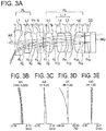
- FIG. 3A is a cross-sectional view showing a lens arrangement of the endoscope objective optical system according to the present example.
- the endoscope objective optical system includes in order from an object side, a front group FL having a negative refractive power as a whole, an aperture stop S, and a rear group RL having a positive refractive power as a whole.
- the endoscope objective optical system of the present example includes in order from the object side, a first lens L1 which is a planoconcave negative lens having a flat surface directed toward the object side, a second meniscus lens L2 having a positive refractive power and having a convex surface directed toward an image side, an infra-red absorption filter F1, the aperture stop S, a third lens L3 which is a biconvex positive lens, a fourth lens L4 which is a biconvex positive lens, a fifth meniscus lens L5 having a negative refractive power and having a concave surface directed toward the object side, a sixth lens L6 having a positive refractive power and having a convex surface directed toward the object side, and a CCD cover glass CG.
- I denotes an image pickup surface
- IMG denotes an image pickup element.
- the front group FL includes the first lens L1 having a negative refractive power and the second meniscus lens L2 having a positive refractive power.
- the rear group RL includes the third lens L3 having a positive refractive power, the fourth lens L4 having a positive refractive power, the fifth meniscus lens L5 having a negative refractive power, and the sixth lens L6 having a positive refractive power.
- a YAG laser cut coating is applied to an object side of the infra-red absorption filter F1
- an LD laser cut coating is applied to an image side of the infra-red absorption filter F1.
- the fourth lens L4 having a positive refractive power and the fifth meniscus lens L5 having a negative refractive power are cemented and form a cemented lens CL1.
- the sixth lens L6 having a positive refractive power and the CCD cover glass CG are cemented.
- Fig. 3B, Fig. 3C, Fig. 3D, and Fig. 3E are aberration diagrams showing a spherical aberration (SA), an astigmatism (AS), a distortion (DT), and a chromatic aberration of magnification (CC) respectively, of the example 2.
- SA spherical aberration
- AS astigmatism
- DT distortion
- CC chromatic aberration of magnification
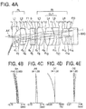
- Fig. 4A is a cross-sectional view showing a lens arrangement of the endoscope objective optical system according to the present example.
- the endoscope objective optical system includes in order from an object side, a front group FL having a negative refractive power as a whole, an aperture stop S, and a rear group RL having a positive refractive power as a whole.
- the endoscope objective optical system of the present example includes in order from the object side, a first lens L1 which is a planoconcave negative lens having a flat surface directed toward the object side, a second meniscus lens L2 having a positive refractive power and having a convex surface directed toward an image side, an infra-red absorption filter F1, the aperture stop S, a third lens L3 which is a biconvex positive lens, a fourth lens L4 which is a biconvex positive lens, a fifth meniscus lens L5 having a negative refractive power and having a concave surface directed toward the object side, a sixth lens L6 having a positive refractive power and having a convex surface directed toward the object side, and a CCD cover glass CG.
- I denotes an image pickup surface
- IMG denotes an image pickup element.
- the front group FL includes the first lens L1 having a negative refractive power and the second meniscus lens L2 having a positive refractive power.
- the rear group RL includes the third lens L3 having a positive refractive power, the fourth lens L4 having a positive refractive power, the fifth meniscus lens L5 having a negative refractive power, and the sixth lens L6 having a positive refractive power.
- a YAG laser cut coating is applied to an object side of the infra-red absorption filter F1
- an LD laser cut coating is applied to an image side of the infra-red absorption filter F1.
- the fourth lens L4 having a positive refractive power and the fifth meniscus lens L5 having a negative refractive power are cemented and form a cemented lens CL1.
- the sixth lens L6 having a positive refractive power and the CCD cover glass CG are cemented.
- Fig. 4B, Fig. 4C, Fig. 4D, and Fig. 4E are aberration diagrams showing a spherical aberration (SA), an astigmatism (AS), a distortion (DT), and a chromatic aberration of magnification (CC) respectively, of the example 3.
- SA spherical aberration
- AS astigmatism
- DT distortion
- CC chromatic aberration of magnification
- Fig. 5A is a cross-sectional view showing a lens arrangement of the endoscope objective optical system according to the present example.
- the endoscope objective optical system includes in order from an object side, a front group FL having a negative refractive power as a whole, an aperture stop S, and a rear group RL having a positive refractive power as a whole.
- the endoscope objective optical system of the present example includes in order from the object side, a first lens L1 which is a planoconcave negative lens having a flat surface directed toward the object side, a second meniscus lens L2 having a positive refractive power and having a convex surface directed toward an image side, an infra-red absorption filter F1, the aperture stop S, a third lens L3 which is a biconvex positive lens, a fourth lens L4 which is a biconvex positive lens, a fifth meniscus lens L5 having a negative refractive power and having a concave surface directed toward the object side, a sixth lens L6 having a positive refractive power and having a convex surface directed toward the object side, and a CCD cover glass CG.
- I denotes an image pickup surface
- IMG denotes an image pickup element.
- the front group FL includes the first lens L1 having a negative refractive power and the second meniscus lens L2 having a positive refractive power.
- the rear group RL includes the third lens L3 having a positive refractive power, the fourth lens L4 having a positive refractive power, the fifth meniscus lens L5 having a negative refractive power, and the sixth lens L6 having a positive refractive power.
- a YAG laser cut coating is applied to an object side of the infra-red absorption filter F1
- an LD laser cut coating is applied to an image side of the infra-red absorption filter F1.
- the fourth lens L4 having a positive refractive power and the fifth meniscus lens L5 having a negative refractive power are cemented and form a cemented lens CL1.
- the sixth lens L6 having a positive refractive power and the CCD cover glass Cg are cemented.
- Fig. 5B, Fig. 5C, Fig. 5D, and Fig. 5E are aberration diagrams showing a spherical aberration (SA), an astigmatism (AS), a distortion (DT), and a chromatic aberration of magnification (CC) respectively, of the example 4.
- SA spherical aberration
- AS astigmatism
- DT distortion
- CC chromatic aberration of magnification
- Fig. 6A is a cross-sectional view showing a lens arrangement of the endoscope objective optical system according to the present example.
- the endoscope objective optical system includes in order from an object side, a front group FL having a negative refractive power as a whole, an aperture stop S, and a rear group RL having a positive refractive power as a whole.
- the endoscope objective optical system of the present example includes in order from the object side, a first lens L1 which is a planoconcave negative lens having a flat surface directed toward the object side, a second meniscus lens L2 having a positive refractive power and having a convex surface directed toward an image side, an infra-red absorption filter F1, the aperture stop S, a third meniscus lens L3 having a positive refractive power and having a convex surface directed toward the image side, a fourth lens L4 which is a biconvex positive lens, a fifth meniscus lens L5 having a negative refractive power and having a concave surface directed toward the object side, a sixth lens L6 having a positive refractive power and having a convex surface directed toward the object side, and a CCD cover glass CG.
- I denotes an image pickup surface
- IMG denotes an image pickup element.
- the front group FL includes the first lens L1 having a negative refractive power and the second meniscus lens L2 having a positive refractive power.
- the rear group RL includes the third meniscus lens L3 having a positive refractive power, the fourth lens L4 having a positive refractive power, the fifth meniscus lens L5 having a negative refractive power, and the sixth lens L6 having a positive refractive power.
- a YAG laser cut coating is applied to an object side of the infra-red absorption filter F1
- an LD laser cut coating is applied to an image side of the infra-red absorption filter F1.
- the fourth lens L4 having a positive refractive power and the fifth meniscus lens L5 having a negative refractive power are cemented and form a cemented lens CL1.
- the sixth lens L6 having a positive refractive power and the CCD cover glass CG are cemented.
- Fig. 6B, Fig. 6C, Fig. 6D, and Fig. 6E are aberration diagrams showing a spherical aberration (SA), an astigmatism (AS), a distortion (DT), and a chromatic aberration of magnification (CC) respectively, of the example 5.
- SA spherical aberration
- AS astigmatism
- DT distortion
- CC chromatic aberration of magnification
- Fig. 7A is a cross-sectional view showing a lens arrangement of the endoscope objective optical system according to the present example.
- the endoscope objective optical system includes in order from an object side, a front group FL having a negative refractive power as a whole, an aperture stop S, and a rear group RL having a positive refractive power as a whole.
- the endoscope objective optical system of the present example includes in order from the object side, a first lens L1 which is a planoconcave negative lens having a flat surface directed toward the object side, a second meniscus lens L2 having a positive refractive power and having a convex surface directed toward an image side, an infra-red absorption filter F1, the aperture stop S, a third meniscus lens L3 having a positive refractive power and having a convex surface directed toward the image side, a fourth lens L4 which is a biconvex positive lens, a fifth meniscus lens L5 having a negative refractive power and having a concave surface directed toward the object side, a sixth lens L6 having a positive refractive power and having a convex surface directed toward the object side, and a CCD cover glass CG.
- I denotes an image pickup surface
- IMG denotes an image pickup element.
- the front group FL includes the first lens L1 having a negative refractive power and the second meniscus lens L2 having a positive refractive power.
- the rear group RL includes the third meniscus lens L3 having a positive refractive power, the fourth lens L4 having a positive refractive power, the fifth meniscus lens L5 having a negative refractive power, and the sixth lens L6 having a positive refractive power.
- a YAG laser cut coating is applied to an object side of the infra-red absorption filter F1
- an LD laser cut coating is applied to an image side of the infra-red absorption filter F1.
- the fourth lens L4 having a positive refractive power and the fifth meniscus lens L5 having a negative refractive power are cemented and form a cemented lens CL1.
- the sixth lens L6 having a positive refractive power and the CCD cover glass CG are cemented.
- Fig. 7B, Fig. 7C, Fig. 7D, and Fig. 7E are aberration diagrams showing a spherical aberration (SA), an astigmatism (AS), a distortion (DT), and a chromatic aberration of magnification (CC) respectively, of the example 6.
- SA spherical aberration
- AS astigmatism
- DT distortion
- CC chromatic aberration of magnification
- Fig. 8A is a cross-sectional view showing a lens arrangement of the endoscope objective optical system according to the present example.
- the endoscope objective optical system includes in order from an object side, a front group FL having a negative refractive power as a whole, an aperture stop S, and a rear group RL having a positive refractive power as a whole.
- the endoscope objective optical system of the present example includes in order from the object side, a first lens L1 which is a planoconcave negative lens having a flat surface directed toward the object side, a second meniscus lens L2 having a positive refractive power and having a convex surface directed toward an image side, an infra-red absorption filter F1, the aperture stop S, a third lens L3 which is a biconvex positive lens, a fourth lens L4 which is a biconvex positive lens, a fifth meniscus lens L5 having a negative refractive power and having a concave surface directed toward the object side, a sixth lens L6 having a positive refractive power and having a convex surface directed toward the object side, and a CCD cover glass CG.
- I denotes an image pickup surface
- IMG denotes an image pickup element.
- the front group FL includes the first lens L1 having a negative refractive power and the second meniscus lens L2 having a positive refractive power.
- the rear group RL includes the third lens L3 having a positive refractive power, the fourth lens L4 having a positive refractive power, the fifth meniscus lens L5 having a negative refractive power, and the sixth lens L6.
- a YAG laser cut coating is applied to an object side of the infra-red absorption filter F1
- an LD laser cut coating is applied to an image side of the infra-red absorption filter F1.
- the fourth lens L4 having a positive refractive power and the fifth meniscus lens L5 having a negative refractive power are cemented and form a cemented lens CL1.
- the sixth lens L6 having a positive refractive power and the CCD cover glass CG are cemented.
- Fig. 8B, Fig. 8C, Fig. 8D, and Fig. 8E are aberration diagrams showing a spherical aberration (SA), an astigmatism (AS), a distortion (DT), and a chromatic aberration of magnification (CC) respectively, of the example 7.
- SA spherical aberration
- AS astigmatism
- DT distortion
- CC chromatic aberration of magnification
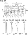
- Fig. 9A is a cross-sectional view showing a lens arrangement of the endoscope objective optical system according to the present example.
- the endoscope objective optical system includes in order from an object side, a front group FL having a negative refractive power as a whole, an aperture stop S, and a rear group RL having a positive refractive power as a whole.
- the endoscope objective optical system of the present example includes in order from the object side, a first lens L1 which is a planoconcave negative lens having a flat surface directed toward the object side, a second meniscus lens L2 having a positive refractive power and having a convex surface directed toward an image side, an infra-red absorption filter F1, the aperture stop S, a third lens L3 which is a biconvex positive lens, a fourth lens L4 which is a biconvex positive lens, a fifth meniscus lens L5 having a negative refractive power and having a concave surface directed toward the object side, a sixth lens L6 having a positive refractive power and having a convex surface directed toward the object side, and a CCD cover glass CG.
- I denotes an image pickup surface
- IMG denotes an image pickup element.
- the front group FL includes the first lens L1 having a negative refractive power and the second meniscus lens L2 having a positive refractive power.
- the rear group RL includes the third lens L3 having a positive refractive power, the fourth lens L4 having a positive refractive power, the fifth meniscus lens L5 having a negative refractive power, and the sixth lens L6 having a positive refractive power.
- a YAG laser cut coating is applied to an object side of the infra-red absorption filter F1
- an LD laser cut coating is applied to an image side of the infra-red absorption filter F1.
- the fourth lens L4 having a positive refractive power and the fifth meniscus lens L5 having a negative refractive power are cemented and form a cemented lens CL1.
- the sixth lens L6 having a positive refractive power and the CCD cover glass CG are cemented.
- Fig. 9B, Fig. 9C, Fig. 9D, and Fig. 9E are aberration diagrams showing a spherical aberration (SA), an astigmatism (AS), a distortion (DT), and a chromatic aberration of magnification (CC) respectively, of the example 8.
- SA spherical aberration
- AS astigmatism
- DT distortion
- CC chromatic aberration of magnification
- Fig. 10A is a cross-sectional view showing a lens arrangement of the endoscope objective optical system according to the present example.
- the endoscope objective optical system includes in order from an object side, a front group FL having a negative refractive power as a whole, an aperture stop S, and a rear group RL having a positive refractive power as a whole.
- the endoscope objective optical system of the present example includes in order from the object side, a first lens L1 which is a planoconcave negative lens having a flat surface directed toward the object side, a second meniscus lens L2 having a positive refractive power and having a convex surface directed toward an image side, an infra-red absorption filter F1, the aperture stop S, a third lens L3 which is a biconvex positive lens, a fourth lens L4 which is a biconvex positive lens, a fifth meniscus lens L5 having a negative refractive power and having a concave surface directed toward the object side, a sixth lens L6 having a positive refractive power and having a convex surface directed toward the object side, and a CCD cover glass CG.
- I denotes an image pickup surface
- IMG denotes an image pickup element.
- the front group FL includes the first lens L1 having a negative refractive power and the second meniscus lens L2 having a positive refractive power.
- the rear group RL includes the third lens L3 having a positive refractive power, the fourth lens L4 having a positive refractive power, the fifth meniscus lens L5 having a negative refractive power, and the sixth lens L6 having a positive refractive power.
- a YAG laser cut coating is applied to an object side of the infra-red absorption filter F1
- an LD laser cut coating is applied to an image side of the infra-red absorption filter F1.
- the fourth lens L4 having a positive refractive power and the fifth meniscus lens L5 having a negative refractive power are cemented and form a cemented lens CL1.
- the sixth lens L6 having a positive refractive power and the CCD cover glass CG are cemented.
- Fig. 10B, Fig. 10C, Fig. 10D, and Fig. 10E are aberration diagrams showing a spherical aberration (SA), an astigmatism (AS), a distortion (DT), and a chromatic aberration of magnification (CC) respectively, of the example 9.
- SA spherical aberration
- AS astigmatism
- DT distortion
- CC chromatic aberration of magnification
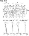
- Fig. 11A is a cross-sectional view showing a lens arrangement of the endoscope objective optical system according to the present example.
- the endoscope objective optical system includes in order from an object side, a front group FL having a negative refractive power as a whole, an aperture stop S, and a rear group RL having a positive refractive power as a whole.
- the endoscope objective optical system of the present example includes in order from the object side, a first lens L1 which is a planoconcave negative lens having a flat surface directed toward the object side, a second meniscus lens L2 having a positive refractive power and having a convex surface directed toward an image side, an infra-red absorption filter F1, the aperture stop S, a third meniscus lens L3 having a positive refractive power and having a convex surface directed toward an image side, a fourth lens L4 which is a biconvex positive lens, a fifth lens L5 which is a biconcave negative lens, a sixth lens L6 having a positive refractive power and having a convex surface directed toward the object side, and a CCD cover glass CG.
- I denotes an image pickup surface
- IMG denotes an image pickup element.
- the front group FL includes the first lens L1 having a negative refractive power and the second meniscus lens L2 having a positive refractive power.
- the rear group RL includes the third meniscus lens L3 having a positive refractive power, the fourth lens L4 having a positive refractive power, the fifth lens L5 having a negative refractive power, and the sixth lens L6 having a positive refractive power.
- a YAG laser cut coating is applied to an object side of the infra-red absorption filter F1
- an LD laser cut coating is applied to an image side of the infra-red absorption filter F1.
- the fourth lens L4 having a positive refractive power and the fifth lens L5 having a negative refractive power are cemented and form a cemented lens CL1.
- the sixth lens L6 having a positive refractive power and the CCD cover glass CG are cemented.
- Fig. 11B, Fig. 11C, Fig 11D, and Fig. 11E are aberration diagrams showing a spherical aberration (SA), an astigmatism (AS), a distortion (DT), and a chromatic aberration of magnification (CC) respectively, of the example 10.
- SA spherical aberration
- AS astigmatism
- DT distortion
- CC chromatic aberration of magnification
- Fig. 12A is a cross-sectional view showing a lens arrangement of the endoscope objective optical system according to the present example.
- the endoscope objective optical system includes in order from an object side, a front group FL having a negative refractive power as a whole, an aperture stop S, and a rear group RL having a positive refractive power as a whole.
- the endoscope objective optical system of the present example includes in order from the object side, a first lens L1 which is a planoconcave negative lens having a flat surface directed toward the object side, a second meniscus lens L2 having a positive refractive power and having a convex surface directed toward an image side, an infra-red absorption filter F1, the aperture stop S, a third meniscus lens L3 having a positive refractive power and having a convex surface directed toward the image side, a fourth lens L4 which is a biconvex positive lens, a fifth lens L5 which is a biconcave negative lens, a sixth lens L6 having a positive refractive power and having a convex surface directed toward the object side, and a CCD cover glass CG.
- I denotes an image pickup surface
- IMG denotes an image pickup element.
- the front group FL includes the first lens L1 having a negative refractive power and the second meniscus lens L2 having a positive refractive power.
- the rear group RL includes the third meniscus lens L3 having a positive refractive power, the fourth lens L4 having a positive refractive power, the fifth lens L5 having a negative refractive power, and the sixth lens L6 having a positive refractive power.
- a YAG laser cut coating is applied to an object side of the infra-red absorption filter F1
- an LD laser cut coating is applied to an image side of the infra-red absorption filter F1.
- the fourth lens L4 having a positive refractive power and the fifth lens L5 having a negative refractive power are cemented and form a cemented lens CL1.
- the sixth lens L6 having a positive refractive power and the CCD cover glass CG are cemented.
- Fig. 12B, Fig. 12C, Fig. 12D, and Fig. 12E are aberration diagrams showing a spherical aberration (SA), an astigmatism (AS), a distortion (DT), and a chromatic aberration of magnification (CC) respectively, of the example 11.
- SA spherical aberration
- AS astigmatism
- DT distortion
- CC chromatic aberration of magnification
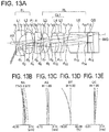
- Fig. 13A is a cross-sectional view showing a lens arrangement of the endoscope objective optical system according to the present example.
- the endoscope objective optical system of the present example includes in order from an object side, a first lens L1 which is a planoconcave negative lens having a flat surface directed toward the object side, a second meniscus lens L2 having a positive refractive power and having a convex surface directed toward an image side, an infra-red absorption filter F1, an aperture stop S, a third meniscus lens L3 having a positive refractive power and having a convex surface directed toward an image side, a fourth lens L4 which is a biconvex positive lens, a fifth meniscus lens L5 having a negative refractive power and having a concave surface directed toward the object side, a sixth lens L6 having a positive refractive power and having a convex surface directed toward the object side, and a CCD cover glass CG.
- I denotes an image pickup surface
- IMG denotes an image pickup element.
- the front group FL includes the first lens L1 having a negative refractive power and the second meniscus lens L2 having a positive refractive power.
- the rear group RL includes the third meniscus lens L3 having a positive refractive power, the fourth lens L4 having a positive refractive power, the fifth meniscus lens L5 having a negative refractive power, and the sixth lens L6 having a positive refractive power.
- a YAG laser cut coating is applied to an object side of the infra-red absorption filter F1
- an LD laser cut coating is applied to an image side of the infra-red absorption filter F1.
- the fourth lens L4 having a positive refractive power and the fifth meniscus lens L5 having a negative refractive power are cemented and form a cemented lens CL1.
- the sixth lens L6 having a positive refractive power and the CCD cover glass CG are cemented.
- Fig. 13B, Fig. 13C, Fig. 13D, and Fig. 13E are aberration diagrams showing a spherical aberration (SA), an astigmatism (AS), a distortion (DT), and a chromatic aberration of magnification (CC) respectively, of the example 12.
- SA spherical aberration
- AS astigmatism
- DT distortion
- CC chromatic aberration of magnification
- r denotes radius of curvature of each lens surface
- d denotes a distance between respective lens surfaces
- nd denotes a refractive index of each lens for a d-line
- ⁇ d denotes an Abbe number for each lens
- FNo denotes an F number
- ⁇ denotes a half angle of view
- IH denotes an image height.
- conditional expressions in each example are shown below.
- the aforementioned endoscope objective optical system may satisfy a plurality of arrangements simultaneously. Making such arrangement is preferable for achieving a favorable endoscope objective optical system. Moreover, combinations of preferable arrangements are voluntary. Furthermore, regarding each conditional expression, only an upper limit value or a lower limit value of a numerical range of a further restricted conditional expression may be restricted.
- the present invention is useful for a high-performance endoscope objective optical system which is small-sized and is capable of securing an adequate observation depth, and which has a wide angle of view, and which makes easy an observation and diagnosis of a pathological lesion.
Landscapes
- Physics & Mathematics (AREA)
- Health & Medical Sciences (AREA)
- Life Sciences & Earth Sciences (AREA)
- Optics & Photonics (AREA)
- Surgery (AREA)
- General Physics & Mathematics (AREA)
- Heart & Thoracic Surgery (AREA)
- Molecular Biology (AREA)
- Pathology (AREA)
- Radiology & Medical Imaging (AREA)
- Biophysics (AREA)
- Engineering & Computer Science (AREA)
- Biomedical Technology (AREA)
- Veterinary Medicine (AREA)
- Nuclear Medicine, Radiotherapy & Molecular Imaging (AREA)
- Animal Behavior & Ethology (AREA)
- Medical Informatics (AREA)
- General Health & Medical Sciences (AREA)
- Public Health (AREA)
- Astronomy & Astrophysics (AREA)
- Lenses (AREA)
- Nonlinear Science (AREA)
- Instruments For Viewing The Inside Of Hollow Bodies (AREA)
Abstract
Description
- The present invention relates to a small-size and bright objective optical system, and particularly, to an endoscope objective optical system.
- Endoscope is an instrument that has been used widely in a medical field and an industrial field. Particularly, in the medical field, from a viewpoint of reducing stress on a patient and improving an accuracy of diagnosis, small-sizing and making the number of pixels large of an image pickup element such as a CCD (charge coupled device) and CMOS (complementary metal-oxide semiconductor) of an endoscope has been progressing, and a pixel pitch has been becoming smaller year by year. Therefore, even for an endoscope objective optical system, facilitating small-sizing while satisfying an optical performance such as widening an angle of view and an aberration correction, has been sought. Small-size endoscope objective optical systems have been proposed in Patent Literatures 1 and 2. Moreover, small-size optical systems for digital cameras have been proposed in Patent Literatures 3 and 4.
-
- Patent Literature 1: Japanese Patent Publication No.
4997348 - Patent Literature 2: Japanese Patent Publication No.
5927368 - Patent Literature 3: Japanese Patent Application Laid-open Publication No.
2008-107478 - Patent Literature 4: Japanese Patent Application Laid-open Publication No.
2006-84886 - The objective optical system disclosed in Patent Literature 1 has optical specifications of a small-size and a large Fno. The objective optical system disclosed in Patent Literature 2 has a small size and a small Fno, and has an arrangement which is not susceptible to have an effect of diffraction. Moreover, this is an objective optical system in which a focus-adjustment job has been made easy by alleviating the sensitivity due to a variation in a focusing position. A zoom lens disclosed in Patent Literature 3 is a small-size and high-performance optical system having a vibration-proof function. The optical system disclosed in Patent Literature 4 is a small-size and high-performance optical system to be used mainly in a small-size image pickup apparatus such as a digital camera.
- In the objective optical system disclosed in Patent Literature 1, it is desirable that the Fno of the objective optical system is in a range satisfying the following conditional expression (A) so as not to have an effect of diffraction.

P denotes a pixel pitch of an image pickup element. - In an optical system with a small pixel pitch, degradation of an optical performance occurs due to diffraction of light. Therefore, in recent years where the pixel pitch has become small with small-sizing and the large number of pixels, the objective optical system disclosed in Japanese Patent Publication No.
4997348 - The objective optical system disclosed in Patent Literature 2, given the situation that the focusing position is shifted due to a load of assembling after the focus adjustment, has an arrangement which is still inadequate for achieving a stable and favorable optical performance. For instance, for fixing the focusing position after the focus adjustment, it is necessary to lock the optical system by a mechanical member and to fix by an adhesive. In this case, there is a possibility of a shift in the focusing position occurred when the optical system is locked, cure shrinkage of the adhesive, and furthermore a shift in the focusing position due to thermal expansion of the mechanical member holding the focusing position, when the adhesive is placed in a high-temperature environment for expediting the curing. Consequently, a phenomenon in which the observation depth differs due to the abovementioned manufacturing variability, despite being the objective optical systems with the same specifications, may occur, and an image may be blurred in an observation of an object at a close distance or an object at a long distance. In that case, a highly-definition observation is not possible, and a problem of degradation of a diagnostic accuracy arises for an operator.
- Furthermore, in the objective optical system of Patent Literature 2, the focusing sensitivity is alleviated by making large a positive refractive power of a field lens cemented to an image pickup element. In this case, for solving the abovementioned problem, it is necessary to further alleviate the focusing sensitivity. However, just by alleviating the focusing sensitivity by making the positive refractive power of the field lens large, an astigmatism becomes large. Consequently, since peripheral performance is deteriorated, further focusing alleviation is difficult.
- In such manner, in the endoscope objective optical systems disclosed in Patent Literatures 1 and 2, when the focusing position is shifted because of the effect of diffraction due to small-sizing or the assembling load, the optical performance is degraded, and therefore it is not applicable.
- Moreover, the optical systems disclosed in Patent Literatures 3 and 4 are a small-size and high-performance. However, a lens arrangement of the optical system, for instance, such as a shape of a lens nearest to object, is not suitable to be used in an endoscope.
- The present invention has been made in view of the abovementioned problems, and an object of the present invention is to provide a high-performance endoscope objective optical system which is small-sized and is capable of securing an adequate observation depth, and which has a wide angle of view, and which makes easy an observation and diagnosis of a pathological lesion.
- To solve the abovementioned problems and to achieve the object, an endoscope objective optical system according to at least some embodiments of the present invention consists of, in order from an object side,
a front group having a negative refractive power as a whole,
an aperture stop, and
a rear group having a positive refractive power as a whole, wherein
the front group includes a first lens which is a single lens having a negative refractive power, and a second lens which is a single lens having a positive refractive power, in order from the object side, and
the rear group includes a third lens which is a single lens having a positive refractive power, a cemented lens of a fourth lens having a positive refractive power and a fifth lens having a negative refractive power, and a sixth lens having a positive refractive power, and
an object-side surface of the first lens is a flat surface, and
the second lens has a meniscus shape with a convex surface directed toward an image side, and
the sixth lens is cemented to an image pickup element, and
the following conditional expression (1) is satisfied:
- D6 denotes a thickness of the sixth lens, and
- F12 denotes a combined focal length from the first lens up to the second lens.
- The present invention shows an effect that it is possible to provide a high-performance endoscope objective optical system which is small-sized and is capable of securing an adequate observation depth, and which has a wide angle of view, and which makes easy an observation and diagnosis of a pathological lesion.
-
-
Fig. 1 is a cross-sectional view showing a lens arrangement of an endoscope objective optical system according an embodiment of the present invention; -
Fig. 2A is a cross-sectional view showing a lens arrangement of an endoscope objective optical system according to an example 1 of the present invention, andFig. 2B, Fig. 2C, Fig. 2D, and Fig. 2E are aberration diagrams showing a spherical aberration (SA), an astigmatism (AS), a distortion (DT), and a chromatic aberration of magnification (CC) respectively, of the example 1; -
Fig. 3A is a cross-sectional view showing a lens arrangement of an endoscope objective optical system according to an example 2 of the present invention, andFig. 3B, Fig. 3C, Fig. 3D, and Fig. 3E are aberration diagrams showing a spherical aberration (SA), an astigmatism (AS), a distortion (DT), and a chromatic aberration of magnification (CC) respectively, of the example 2; -
Fig. 4A is a cross-sectional view showing a lens arrangement of an endoscope objective optical system according to an example 3 of the present invention, andFig. 4B, Fig. 4C, Fig. 4D, and Fig. 4E are aberration diagrams showing a spherical aberration (SA), an astigmatism (AS), a distortion (DT), and a chromatic aberration of magnification (CC) respectively, of the example 3; -
Fig. 5A is a cross-sectional view showing a lens arrangement of an endoscope objective optical system according to an example 4 of the present invention, andFig. 5B, Fig. 5C, Fig. 5D, and Fig. 5E are aberration diagrams showing a spherical aberration (SA), an astigmatism (AS), a distortion (DT), and a chromatic aberration of magnification (CC) respectively, of the example 4; -
Fig. 6A is a cross-sectional view showing a lens arrangement of an endoscope objective optical system according to an example 5 of the present invention, andFig. 6B, Fig. 6C, Fig. 6D, and Fig. 6E are aberration diagrams showing a spherical aberration (SA), an astigmatism (AS), a distortion (DT), and a chromatic aberration of magnification (CC) respectively, of the example 5; -
Fig. 7A is a cross-sectional view showing a lens arrangement of an endoscope objective optical system according to an example 6 of the present invention, andFig. 7B, Fig. 7C, Fig. 7D, and Fig. 7E are aberration diagrams showing a spherical aberration (SA), an astigmatism (AS), a distortion (DT), and a chromatic aberration of magnification (CC) respectively, of the example 6; -
Fig. 8A is a cross-sectional view showing a lens arrangement of an endoscope objective optical system according to an example 7 of the present invention, andFig. 8B, Fig. 8C, Fig. 8D, and Fig. 8E are aberration diagrams showing a spherical aberration (SA), an astigmatism (AS), a distortion (DT), and a chromatic aberration of magnification (CC) respectively, of the example 7; -
Fig. 9A is a cross-sectional view showing a lens arrangement of an endoscope objective optical system according to an example 8 of the present invention, andFig. 9B, Fig. 9C, Fig. 9D, and Fig. 9E are aberration diagrams showing a spherical aberration (SA), an astigmatism (AS), a distortion (DT), and a chromatic aberration of magnification (CC) respectively, of the example 8; -
Fig. 10A is a cross-sectional view showing a lens arrangement of an endoscope objective optical system according to an example 9 of the present invention, andFig. 10B, Fig. 10C, Fig. 10D, and Fig. 10E are aberration diagrams showing a spherical aberration (SA), an astigmatism (AS), a distortion (DT), and a chromatic aberration of magnification (CC) respectively, of the example 9; -
Fig. 11A is a cross-sectional view showing a lens arrangement of an endoscope objective optical system according to an example 10 of the present invention, andFig. 11B, Fig. 11C, Fig. 11D, and Fig. 11E are aberration diagrams showing a spherical aberration (SA), an astigmatism (AS), a distortion (DT), and a chromatic aberration of magnification (CC) respectively, of the example 10; -
Fig. 12A is a cross-sectional view showing a lens arrangement of an endoscope objective optical system according to an example 11 of the present invention, andFig. 12B, Fig. 12C, Fig. 12D, and Fig. 12E are aberration diagrams showing a spherical aberration (SA), an astigmatism (AS), a distortion (DT), and a chromatic aberration of magnification (CC) respectively, of the example 11; and -
Fig. 13A is a cross-sectional view showing a lens arrangement of an endoscope objective optical system according to an example 12 of the present invention, andFig. 13B, Fig. 13C, Fig. 13D, and Fig. 13E are aberration diagrams showing a spherical aberration (SA), an astigmatism (AS), a distortion (DT), and a chromatic aberration of magnification (CC) respectively, of the example 12. - An endoscope objective optical system according to an embodiment will be described below in detail by referring to the accompanying diagrams. However, the present invention is not restricted to the embodiments and the examples described below.
-
Fig. 1 is a cross-sectional view showing a lens arrangement of an endoscope objective optical system according to an embodiment of the present invention. - The endoscope objective optical system of the present embodiment consists of, in order from an object side, a front group FL having a negative refractive power as a whole, an aperture stop S, and a rear group RL having a positive refractive power as a whole, wherein the front group FL includes a first lens L1 which is a single lens having a negative refractive power, and a second lens L2 which is a single lens having a positive refractive power, in order from the object side, and the rear group RL includes a third lens L3 which is a single lens having a positive refractive power, a cemented lens CL1 of a fourth lens L4 having a positive refractive power and a fifth lens L5 having a negative refractive power, and a sixth lens L6 having a positive refractive power, and an object-side surface of the first lens L1 is a flat surface, and the second lens L2 has a meniscus shape with a convex surface directed toward an image side, and the sixth lens L6 is cemented to an image pickup element IMG, and the following conditional expression (1) is satisfied:

- D6 denotes a thickness of the sixth lens L6, and
- F12 denotes a combined focal length from the first lens L1 up to the second lens L2.
- Moreover, the aperture stop S is formed on an image-side surface of an infra-red absorption filter F1. Moreover, a cover glass CG for preventing the image pickup element IMG from being scratched is stuck to an image-side surface I of the image pickup element IMG. The sixth lens L6 is cemented to the cover glass CG. Consequently, the sixth lens L6 is cemented to the image pickup element IMG.
- Reasons for and effects of adopting such arrangement in the present embodiment will be described below. For arranging a small-size and high-performance endoscope objective optical system that can be used in an endoscope, firstly, the first lens L1 having a negative refractive power, of which a surface nearest to object is a flat surface, is disposed, and on an image side thereof, a second lens L2 having a positive refractive power and having a meniscus shape with a convex surface directed toward the image side, is disposed.
- In such manner, a retro-focus arrangement is adopted, and the second lens L2 having a positive refractive power is disposed such that a lens diameter does not become large, while correcting an aberration at the first lens L1. Accordingly, a small-size and high-performance objective optical system suitable for an endoscope is arranged.
- Moreover, for the first lens L1, it is preferable to make the following arrangement. In an observation by an endoscope, when a dirt or blood is adhered to a lens surface on the object side of the first lens L1, cleaning of the lens surface is carried out by injecting water from a nozzle provided at a front-end of the endoscope. At the time of cleaning, when a shape of the lens surface on the object side of the first lens L1 is a convex shape, the dirt is hard to be removed. Moreover, when the shape of the lens surface on the object side of the first lens L1 is a concave shape, the water removal is not favorable due to water being accumulated. Furthermore, when the lens surface on the object side of the first lens L1 is convex-shaped, scratching and cracking due to an impact are susceptible to occur. For this reason, the first lens L1 having a negative refractive power is let to be a planoconcave lens, and the first lens L1 having a negative refractive power is disposed such that the flat surface is directed toward the object side. By making such arrangement, the water removal during the observation is made favorable and the cracking of lens due to an impact is reduced.
- Moreover, by disposing a positive lens group for holding a positive refractive power contributing mainly to image formation, on the image side of the second lens L2, an occurrence of an aberration is suppressed despite of Fno being made small and bright, and a refractive power distribution necessary for small-sizing is made.
- Moreover, a cemented lens of a positive lens and a negative lens is disposed at a position on the image side of the third lens L3, at which a peripheral light-ray height becomes high. According, a chromatic aberration is corrected.
- Furthermore, the sixth lens L6 having a positive refractive power which is cemented to the image pickup element IMG is disposed on the image side in the rear group RL. Accordingly, even when an optical magnification is increased, and the focusing position is varied, it is possible to achieve an optical performance with a small effect thereon.
- However, as mentioned above, only by making the positive refractive power of the sixth lens L6 large and alleviating the focusing sensitivity, the astigmatism is deteriorated and it is not possible to secure a favorable optical performance. Therefore, it is necessary to make the sixth lens L6 thick, to increase the optical magnification by moving a curved surface of the lens away from an image plane, and to alleviate the focusing sensitivity. Moreover, for small-sizing and suppressing each aberration, it is desirable that the arrangement is made to satisfy the following conditional expression (1):

- D6 denotes the thickness of the sixth lens L6, and
- F12 denotes the combined focal length from the first lens L1 up to the second lens L2.
- Conditional expression (1) is related to a ratio of the thickness of the sixth lens L6 and the combined focal length from the first lens L1 up to the second lens L2.
- In a case of exceeding an upper limit value of conditional expression (1), the astigmatism becomes substantial due to weakening of the negative refractive power of the first lens L1 and the second lens L2, and it is not possible to achieve a high definition image quality and a wide visual field. Moreover, the curved surface of the sixth lens L6 becomes close to the image plane, and it is not possible to achieve an adequate focusing alleviation effect. Consequently, the endoscope objective optical system becomes weak to the focusing-position shift due to the manufacturing variability.
- In a case of falling below a lower limit value of conditional expression (1), it is possible to achieve an adequate focusing alleviation effect, but the negative refractive power of the first lens L1 and the second lens L2 becomes excessively large, and an aberration such as a coma is deteriorated. Moreover, since, either an overall length of the optical system becomes long due to the curved surface of the sixth lens L6 being moved away from the image plane or a back focus for focusing cannot be secured, it is not possible to achieve a small-size and high definition image quality.
- It is more preferable that the following conditional expression (1') be satisfied instead of conditional expression (1) .

- It is even more preferable that the following conditional expression (1") be satisfied instead of conditional expression (1) .

- Moreover, for making an arrangement of the retro-focus type, the first lens L1 having a negative refractive power is required to have a comparatively large negative refractive power. However, as mentioned above, when the negative refractive power of the first lens L1 is made excessively large, aberrations such as the coma may be deteriorated. Moreover, since the fourth lens L4 having a positive refractive power is disposed far from the aperture stop S, light-ray height increases in the fourth lens L4. Therefore, in the fourth lens L4, a balance of the coma of the peripheral performance and each chromatic aberration is kept. Accordingly, by setting appropriately the refractive power of the first lens L1 having a negative refractive power and the fourth lens L4 having a positive refractive power, even in the endoscope objective optical system with a fast Fno, in which the back-focus is secured while the focusing sensitivity being alleviated adequately, it is possible to take an overall aberration balance.
- Therefore, according to a preferable aspect of the present embodiment, it is desirable that the following conditional expression (2) is satisfied:

- F4 denotes a focal length of the fourth lens L4, and
- F1 denotes a focal length of the first lens L1.
- Conditional expression (2) is related to a ratio of the focal length of the fourth lens L4 and the focal length of the first lens L1.
- In a case of exceeding an upper limit value of conditional expression (2), the negative refractive power becomes excessively large, and the coma, without being corrected thoroughly, is deteriorated, and correction of the chromatic aberration becomes inadequate.
- In a case of falling below a lower limit value of conditional expression (2), either a lens diameter becomes excessively large and the small-sizing cannot be fulfilled, or the chromatic aberration is corrected excessively.
- It is more preferable that the following conditional expression (2') be satisfied instead of conditional expression (2) .

- It is even more preferable that the following conditional expression (2") be satisfied instead of conditional expression (2).

- Moreover, since the first lens L1 and the fifth lens L5 being disposed far away from the aperture stop S, there is an effect on optical performance at a peripheral portion of an image field, and since a peripheral light-ray height also becomes high, there is an effect on the lens diameter as well. For cancelling an aberration at the peripheral portion of the image field, an arrangement of the fifth lens L5 having a negative refractive power at which the peripheral light-ray height becomes high, becomes significant.
- Therefore, according to a preferable aspect of the present embodiment, it is desirable that the following conditional expression (3) is satisfied:

- F5 denotes a focal length of the fifth lens L5, and
- F1 denotes the focal length of the first lens L1.
- In a case of exceeding an upper limit value of conditional expression (3), the negative refractive power becomes excessively large, and either the coma, not being corrected thoroughly, is deteriorated, or correction of a chromatic aberration of magnification becomes inadequate.
- In a case of falling below a lower limit value of conditional expression (3), either a lens diameter becomes excessively large or correction of the chromatic aberration of magnification becomes excessive.
- It is more preferable that the following conditional expression (3') be satisfied instead of conditional expression (3) .

- It is even more preferable that the following conditional expression (3") be satisfied instead of conditional expression (3) .

- Moreover, in an objective optical system with a fast Fno, correction of a spherical aberration and the coma tend to be disadvantageous. The positive refractive power which is major in the lens arrangement of the present embodiment is secured by the third lens L3, and the fourth lens L4 in the cemented lens CL1. Therefore, an aberration is susceptible to occur at these lenses. Moreover, the positive refractive power forming the retro-focus arrangement is also held by the third lens L3 and the fourth lens L4, and has a relationship with the size of the objective optical system. Particularly, since a height of an axial light ray becomes high, an aberrational effect is high, and moreover, it is easy to secure the refractive power by the third lens L3 which is not cemented, and contribution to securing the back focus at the time of focusing alleviation is also high. Therefore, it is necessary to set appropriately the refractive power of the third lens L3 and the fourth lens L4.
- Therefore, according to a preferable aspect of the present embodiment, it is desirable that the following conditional expression (4) is satisfied:

- R3R denotes a radius of curvature of an image side of the third lens L3, and
- R4L denotes a radius of curvature of an object side of the fourth lens L4.
- Conditional expression (4) is regarding an appropriate relationship of the radius of curvature of the image side of the third lens L3 and the radius of curvature of the object side of the fourth lens L4.
- In a case of exceeding an upper limit value of conditional expression (4), since correction of the coma is degraded, and the overall length also becomes long, it is not possible to achieve a small-size and high definition image quality.
- In a case of falling below a lower limit value of conditional expression (4), the spherical aberration is deteriorated, and it is not possible to secure back focus which is necessary for focusing.
- It is more preferable that the following conditional expression (4') be satisfied instead of conditional expression (4).

- It is even more preferable that the following conditional expression (4") be satisfied instead of conditional expression (4) .

- Moreover, the first lens L1 having a negative refractive power and the second lens L2 having a positive refractive power disposed in the front group FL play a significant role in widening the angle of view and small-sizing of the optical system. In this case, the radius of curvature of the second lens L2 having a positive refractive power contributes to occurrence of the coma and the chromatic aberration. Moreover, although the radius of curvature of the sixth lens L6 plays a significant role in alleviating the focusing sensitivity, it contributes to an occurrence of astigmatism.
- Therefore, according to a preferable aspect of the present embodiment, it is desirable that the following conditional expressions (5) and (6) are satisfied for taking a balance of an amount of each aberration that occurs, the lens diameter and the focusing sensitivity. Preferably, it is desirable that conditional expressions (5) and (6) are satisfied simultaneously:


- F12 denotes the combined focal length from the first lens up to the second lens L2,
- R6L denotes a radius of curvature of an object side of the sixth lens L6, and
- R2L denotes a radius of curvature of an object side of the second lens L2.
- Conditional expression (5) is related to a ratio of the combined focal length from the first lens L1 up to the second lens L2, and the radius of curvature of the object side of the sixth lens L6. Conditional expression (6) is related to a ratio of the radius of curvature of the second lens L2 and the radius of curvature of the sixth lens L6.
- In a case of exceeding an upper limit value of conditional expression (5), either the coma is deteriorated or the astigmatism is deteriorated.
- In a case of falling below a lower limit value of conditional expression (5), since either the lens diameter becomes large or an adequate focusing alleviation effect cannot be achieved, endoscope objective optical system becomes weak to a shift in focusing position due to the manufacturing variability.
- In a case of exceeding an upper limit value of conditional expression (6), either the chromatic aberration is deteriorated or the astigmatism is deteriorated.
- In a case of falling below a lower limit value of conditional expression (6), since either the coma is deteriorated or an adequate focusing alleviation effect cannot be achieved, the endoscope objective optical system becomes weak to the shift in focusing position due to the manufacturing variability.
- It is more preferable that the following conditional expressions (5') and (6') be satisfied instead of conditional expressions (5) and (6).


- It is even more preferable that the following conditional expressions (5") and (6") be satisfied instead of conditional expressions (5) and (6).


- The light-ray height being high at a surface on the image side of the fourth lens L4, it contributes largely to correction of each chromatic aberration. Moreover, at a surface on the image side of the third lens L3, since an amount of the coma that occurs and a height of an axial light ray become high, it contributes to the spherical aberration as well.
- Therefore, according to a preferable aspect of the present embodiment, it is desirable that the following conditional expression (7) be satisfied for correction of each chromatic aberration and each aberration:

- R4R denotes a radius of curvature of an image side of the fourth lens L4, and
- R3R denotes the radius of curvature of an image side of the third lens L3.
- Conditional expression (7) is related to a ratio of the radius of curvature of the image side of the fourth lens L4 and the radius of curvature of the image side of the third lens L3.
- In a case of exceeding an upper limit value of conditional expression (7), either correction of the chromatic aberration becomes inadequate or the spherical aberration is deteriorated, and also it is not possible to secure the back focus necessary for focusing.
- In a case of falling below a lower limit value of conditional expression (7), since either correction of the chromatic aberration becomes excessive or the coma is deteriorated, and the overall length of the optical system becomes long, it is not possible to achieve a small-size and high definition image quality.
- It is more preferable that the following conditional expression (7') be satisfied instead of conditional expression (7) .

- It is even more preferable that the following conditional expression (7") be satisfied instead of conditional expression (7) .

- Moreover, according to a preferable aspect of the present embodiment, it is desirable that the following conditional expression (8) be satisfied:

- R4R denotes the radius of curvature of an image side of the fourth lens L4, and
- R2R denotes a radius of curvature of an image side of the second lens L2.
- Conditional expression (8) is related to a ratio of the radius of curvature of the image side of the fourth lens L4 and the radius of curvature of the image side of the second lens L2.
- In the endoscope which is small-size and is suitable for an image pickup element with a large number of pixels, correction of the chromatic aberration is significant. Conditional expression (8) is related to the chromatic aberration as conditional expression (7), and a surface on the image side of the second lens L2 contributes substantially to each chromatic aberration.
- In a case of exceeding an upper limit value of conditional expression (8), either correction of the chromatic aberration of magnification becomes inadequate or correction of a longitudinal chromatic aberration becomes inadequate, and it is also not possible to secure the back focus which is necessary for focusing.
- In a case of falling below a lower limit value of conditional expression (8), since either correction of the chromatic aberration of magnification becomes excessive or correction of the longitudinal chromatic aberration becomes excessive, and the overall length of the optical system becomes long, it is not possible to achieve a small-size and high definition image quality.
- It is more preferable that the following conditional expression (8') be satisfied instead of conditional expression (8) .

- It is even more preferable that the following conditional expression (8") be satisfied instead of conditional expression (8) .

- Moreover, for making the retro-focus arrangement, the third lens L3 having a positive refractive power has a comparatively large refractive power. Consequently, an amount of aberration that occurs also becomes large.
- Therefore, according to a preferable aspect of the present embodiment, it is desirable that the following conditional expression (9) is satisfied:

- R3R denotes the radius of curvature of an image side of the third lens L3, and
- R3L denotes a radius of curvature of an object side of the third lens L3.
- Conditional expression (9) is related to a ratio of the radius of curvature of the image side of the third lens L3 and the radius of curvature of the object side of the third lens L3.
- In a case of exceeding an upper limit value of conditional expression (9), the coma is deteriorated, and also the overall length of the optical system becomes long.
- In a case of falling below a lower limit value of conditional expression (9), correction of the chromatic aberration of magnification becomes inadequate, and also it is not possible to secure the back focus necessary for focusing.
- It is more preferable that the following conditional expression (9') be satisfied instead of conditional expression (9) .

- It is even more preferable that the following conditional expression (9") be satisfied instead of conditional expression (9).

- The cemented lens CL1 of the fourth lens L4 and the fifth lens L5 contributes largely to correction of each chromatic aberration, and the positive refractive power of the sixth lens L6 contributes largely to alleviation of the focusing sensitivity.
- Therefore, for fulfilling alleviation of the focusing sensitivity while correcting the chromatic aberration, according to a preferable aspect of the present embodiment, it is desirable that the following conditional expression (10) be satisfied:

- F45 denotes a focal length of the cemented lens of the fourth lens L4 and the fifth lens L5, and
- F6 denotes a focal length of the sixth lens L6.
- In a case of exceeding an upper limit value of conditional expression (10), either correction of the chromatic aberration of magnification becomes excessive or the astigmatism is deteriorated.
- In a case of falling below a lower limit value of conditional expression (10), since either the chromatic aberration of magnification becomes inadequate or it is not possible to achieve an adequate focusing alleviation effect, the endoscope objective optical system becomes weak to the focusing-position shift due to the manufacturing variability.
- It is more preferable that the following conditional expression (10') be satisfied instead of conditional expression (10).

- It is even more preferable that the following conditional expression (10") be satisfied instead of conditional expression (10) .

- Each example of the present invention will be described below.
- An endoscope objective optical system according to an example 1 will be described below.
Fig. 2A is a cross-sectional view showing a lens arrangement of the endoscope objective optical system according to the present example. - In the present example, the endoscope objective optical system includes in order from an object side, a front group FL having a negative refractive power as a whole, an aperture stop S, and a rear group RL having a positive refractive power as a whole.
- The endoscope objective optical system of the present example includes in order from the object side, a first lens L1 which is a planoconcave negative lens having a flat surface directed toward the object side, a second meniscus lens L2 having a positive refractive power and having a convex surface directed toward an image side, an infra-red absorption filter F1, the aperture stop S, a third lens L3 which is a biconvex positive lens, a fourth lens L4 which is a biconvex positive lens, a fifth meniscus lens L5 having a negative refractive power and having a concave surface directed toward the object side, a sixth lens L6 having a positive refractive power and having a convex surface directed toward the object side, and a CCD cover glass CG. In this example, I denotes an image pickup surface and IMG denotes an image pickup element.
- The front group FL includes the first lens L1 having a negative refractive power and the second meniscus lens L2 having a positive refractive power. The rear group RL includes the third lens L3 having a positive refractive power, the fourth lens L4 having a positive refractive power, the fifth meniscus lens L5 having a negative refractive power, and the sixth lens L6 having a positive refractive power.
- Moreover, a YAG (yttrium aluminum garnet) laser cut coating is applied to an object side of the infra-red absorption filter F1, and an LD laser cut coating is applied to an image side of the infra-red absorption filter F1.
- The fourth lens L4 having a positive refractive power and the fifth meniscus lens L5 having a negative refractive power are cemented and form a cemented lens CL1. The sixth lens L6 having a positive refractive power and the CCD cover glass CG are cemented.
-
Fig. 2B, Fig. 2C, Fig. 2D, and Fig. 2E are aberration diagrams showing a spherical aberration (AS), an astigmatism (AS), a distortion (DT), and a chromatic aberration of magnification (CC) respectively, of the example 1. - An endoscope objective optical system according to an example 2 will be described below.
Fig. 3A is a cross-sectional view showing a lens arrangement of the endoscope objective optical system according to the present example. - In the present example, the endoscope objective optical system includes in order from an object side, a front group FL having a negative refractive power as a whole, an aperture stop S, and a rear group RL having a positive refractive power as a whole.
- The endoscope objective optical system of the present example includes in order from the object side, a first lens L1 which is a planoconcave negative lens having a flat surface directed toward the object side, a second meniscus lens L2 having a positive refractive power and having a convex surface directed toward an image side, an infra-red absorption filter F1, the aperture stop S, a third lens L3 which is a biconvex positive lens, a fourth lens L4 which is a biconvex positive lens, a fifth meniscus lens L5 having a negative refractive power and having a concave surface directed toward the object side, a sixth lens L6 having a positive refractive power and having a convex surface directed toward the object side, and a CCD cover glass CG. In this example, I denotes an image pickup surface and IMG denotes an image pickup element.
- The front group FL includes the first lens L1 having a negative refractive power and the second meniscus lens L2 having a positive refractive power. The rear group RL includes the third lens L3 having a positive refractive power, the fourth lens L4 having a positive refractive power, the fifth meniscus lens L5 having a negative refractive power, and the sixth lens L6 having a positive refractive power.
- Moreover, a YAG laser cut coating is applied to an object side of the infra-red absorption filter F1, and an LD laser cut coating is applied to an image side of the infra-red absorption filter F1.
- The fourth lens L4 having a positive refractive power and the fifth meniscus lens L5 having a negative refractive power are cemented and form a cemented lens CL1. The sixth lens L6 having a positive refractive power and the CCD cover glass CG are cemented.
-
Fig. 3B, Fig. 3C, Fig. 3D, and Fig. 3E are aberration diagrams showing a spherical aberration (SA), an astigmatism (AS), a distortion (DT), and a chromatic aberration of magnification (CC) respectively, of the example 2. - An endoscope objective optical system according to an example 3 will be described below.
Fig. 4A is a cross-sectional view showing a lens arrangement of the endoscope objective optical system according to the present example. - In the present example, the endoscope objective optical system includes in order from an object side, a front group FL having a negative refractive power as a whole, an aperture stop S, and a rear group RL having a positive refractive power as a whole.
- The endoscope objective optical system of the present example includes in order from the object side, a first lens L1 which is a planoconcave negative lens having a flat surface directed toward the object side, a second meniscus lens L2 having a positive refractive power and having a convex surface directed toward an image side, an infra-red absorption filter F1, the aperture stop S, a third lens L3 which is a biconvex positive lens, a fourth lens L4 which is a biconvex positive lens, a fifth meniscus lens L5 having a negative refractive power and having a concave surface directed toward the object side, a sixth lens L6 having a positive refractive power and having a convex surface directed toward the object side, and a CCD cover glass CG. In this example, I denotes an image pickup surface and IMG denotes an image pickup element.
- The front group FL includes the first lens L1 having a negative refractive power and the second meniscus lens L2 having a positive refractive power. The rear group RL includes the third lens L3 having a positive refractive power, the fourth lens L4 having a positive refractive power, the fifth meniscus lens L5 having a negative refractive power, and the sixth lens L6 having a positive refractive power.
- Moreover, a YAG laser cut coating is applied to an object side of the infra-red absorption filter F1, and an LD laser cut coating is applied to an image side of the infra-red absorption filter F1.
- The fourth lens L4 having a positive refractive power and the fifth meniscus lens L5 having a negative refractive power are cemented and form a cemented lens CL1. The sixth lens L6 having a positive refractive power and the CCD cover glass CG are cemented.
-
Fig. 4B, Fig. 4C, Fig. 4D, and Fig. 4E are aberration diagrams showing a spherical aberration (SA), an astigmatism (AS), a distortion (DT), and a chromatic aberration of magnification (CC) respectively, of the example 3. - An endoscope objective optical system according to an example 4 will be described below.
Fig. 5A is a cross-sectional view showing a lens arrangement of the endoscope objective optical system according to the present example. - In the present example, the endoscope objective optical system includes in order from an object side, a front group FL having a negative refractive power as a whole, an aperture stop S, and a rear group RL having a positive refractive power as a whole.
- The endoscope objective optical system of the present example includes in order from the object side, a first lens L1 which is a planoconcave negative lens having a flat surface directed toward the object side, a second meniscus lens L2 having a positive refractive power and having a convex surface directed toward an image side, an infra-red absorption filter F1, the aperture stop S, a third lens L3 which is a biconvex positive lens, a fourth lens L4 which is a biconvex positive lens, a fifth meniscus lens L5 having a negative refractive power and having a concave surface directed toward the object side, a sixth lens L6 having a positive refractive power and having a convex surface directed toward the object side, and a CCD cover glass CG. In this example, I denotes an image pickup surface and IMG denotes an image pickup element.
- The front group FL includes the first lens L1 having a negative refractive power and the second meniscus lens L2 having a positive refractive power. The rear group RL includes the third lens L3 having a positive refractive power, the fourth lens L4 having a positive refractive power, the fifth meniscus lens L5 having a negative refractive power, and the sixth lens L6 having a positive refractive power.
- Moreover, a YAG laser cut coating is applied to an object side of the infra-red absorption filter F1, and an LD laser cut coating is applied to an image side of the infra-red absorption filter F1.
- The fourth lens L4 having a positive refractive power and the fifth meniscus lens L5 having a negative refractive power are cemented and form a cemented lens CL1. The sixth lens L6 having a positive refractive power and the CCD cover glass Cg are cemented.
-
Fig. 5B, Fig. 5C, Fig. 5D, and Fig. 5E are aberration diagrams showing a spherical aberration (SA), an astigmatism (AS), a distortion (DT), and a chromatic aberration of magnification (CC) respectively, of the example 4. - An endoscope objective optical system according to an example 5 will be described below.
Fig. 6A is a cross-sectional view showing a lens arrangement of the endoscope objective optical system according to the present example. - In the present example, the endoscope objective optical system includes in order from an object side, a front group FL having a negative refractive power as a whole, an aperture stop S, and a rear group RL having a positive refractive power as a whole.
- The endoscope objective optical system of the present example includes in order from the object side, a first lens L1 which is a planoconcave negative lens having a flat surface directed toward the object side, a second meniscus lens L2 having a positive refractive power and having a convex surface directed toward an image side, an infra-red absorption filter F1, the aperture stop S, a third meniscus lens L3 having a positive refractive power and having a convex surface directed toward the image side, a fourth lens L4 which is a biconvex positive lens, a fifth meniscus lens L5 having a negative refractive power and having a concave surface directed toward the object side, a sixth lens L6 having a positive refractive power and having a convex surface directed toward the object side, and a CCD cover glass CG. In this example, I denotes an image pickup surface and IMG denotes an image pickup element.
- The front group FL includes the first lens L1 having a negative refractive power and the second meniscus lens L2 having a positive refractive power. The rear group RL includes the third meniscus lens L3 having a positive refractive power, the fourth lens L4 having a positive refractive power, the fifth meniscus lens L5 having a negative refractive power, and the sixth lens L6 having a positive refractive power.
- Moreover, a YAG laser cut coating is applied to an object side of the infra-red absorption filter F1, and an LD laser cut coating is applied to an image side of the infra-red absorption filter F1.
- The fourth lens L4 having a positive refractive power and the fifth meniscus lens L5 having a negative refractive power are cemented and form a cemented lens CL1. The sixth lens L6 having a positive refractive power and the CCD cover glass CG are cemented.
-
Fig. 6B, Fig. 6C, Fig. 6D, and Fig. 6E are aberration diagrams showing a spherical aberration (SA), an astigmatism (AS), a distortion (DT), and a chromatic aberration of magnification (CC) respectively, of the example 5. - An endoscope objective optical system according to an example 6 will be described below.
Fig. 7A is a cross-sectional view showing a lens arrangement of the endoscope objective optical system according to the present example. - In the present example, the endoscope objective optical system includes in order from an object side, a front group FL having a negative refractive power as a whole, an aperture stop S, and a rear group RL having a positive refractive power as a whole.
- The endoscope objective optical system of the present example includes in order from the object side, a first lens L1 which is a planoconcave negative lens having a flat surface directed toward the object side, a second meniscus lens L2 having a positive refractive power and having a convex surface directed toward an image side, an infra-red absorption filter F1, the aperture stop S, a third meniscus lens L3 having a positive refractive power and having a convex surface directed toward the image side, a fourth lens L4 which is a biconvex positive lens, a fifth meniscus lens L5 having a negative refractive power and having a concave surface directed toward the object side, a sixth lens L6 having a positive refractive power and having a convex surface directed toward the object side, and a CCD cover glass CG. In this example, I denotes an image pickup surface and IMG denotes an image pickup element.
- The front group FL includes the first lens L1 having a negative refractive power and the second meniscus lens L2 having a positive refractive power. The rear group RL includes the third meniscus lens L3 having a positive refractive power, the fourth lens L4 having a positive refractive power, the fifth meniscus lens L5 having a negative refractive power, and the sixth lens L6 having a positive refractive power.
- Moreover, a YAG laser cut coating is applied to an object side of the infra-red absorption filter F1, and an LD laser cut coating is applied to an image side of the infra-red absorption filter F1.
- The fourth lens L4 having a positive refractive power and the fifth meniscus lens L5 having a negative refractive power are cemented and form a cemented lens CL1. The sixth lens L6 having a positive refractive power and the CCD cover glass CG are cemented.
-
Fig. 7B, Fig. 7C, Fig. 7D, and Fig. 7E are aberration diagrams showing a spherical aberration (SA), an astigmatism (AS), a distortion (DT), and a chromatic aberration of magnification (CC) respectively, of the example 6. - An endoscope objective optical system according to an example 7 will be described below.
Fig. 8A is a cross-sectional view showing a lens arrangement of the endoscope objective optical system according to the present example. - In the present example, the endoscope objective optical system includes in order from an object side, a front group FL having a negative refractive power as a whole, an aperture stop S, and a rear group RL having a positive refractive power as a whole.
- The endoscope objective optical system of the present example includes in order from the object side, a first lens L1 which is a planoconcave negative lens having a flat surface directed toward the object side, a second meniscus lens L2 having a positive refractive power and having a convex surface directed toward an image side, an infra-red absorption filter F1, the aperture stop S, a third lens L3 which is a biconvex positive lens, a fourth lens L4 which is a biconvex positive lens, a fifth meniscus lens L5 having a negative refractive power and having a concave surface directed toward the object side, a sixth lens L6 having a positive refractive power and having a convex surface directed toward the object side, and a CCD cover glass CG. In this example, I denotes an image pickup surface and IMG denotes an image pickup element.
- The front group FL includes the first lens L1 having a negative refractive power and the second meniscus lens L2 having a positive refractive power. The rear group RL includes the third lens L3 having a positive refractive power, the fourth lens L4 having a positive refractive power, the fifth meniscus lens L5 having a negative refractive power, and the sixth lens L6.
- Moreover, a YAG laser cut coating is applied to an object side of the infra-red absorption filter F1, and an LD laser cut coating is applied to an image side of the infra-red absorption filter F1.
- The fourth lens L4 having a positive refractive power and the fifth meniscus lens L5 having a negative refractive power are cemented and form a cemented lens CL1. The sixth lens L6 having a positive refractive power and the CCD cover glass CG are cemented.
-
Fig. 8B, Fig. 8C, Fig. 8D, and Fig. 8E are aberration diagrams showing a spherical aberration (SA), an astigmatism (AS), a distortion (DT), and a chromatic aberration of magnification (CC) respectively, of the example 7. - An endoscope objective optical system according to an example 8 will be described below.
Fig. 9A is a cross-sectional view showing a lens arrangement of the endoscope objective optical system according to the present example. - In the present example, the endoscope objective optical system includes in order from an object side, a front group FL having a negative refractive power as a whole, an aperture stop S, and a rear group RL having a positive refractive power as a whole.
- The endoscope objective optical system of the present example includes in order from the object side, a first lens L1 which is a planoconcave negative lens having a flat surface directed toward the object side, a second meniscus lens L2 having a positive refractive power and having a convex surface directed toward an image side, an infra-red absorption filter F1, the aperture stop S, a third lens L3 which is a biconvex positive lens, a fourth lens L4 which is a biconvex positive lens, a fifth meniscus lens L5 having a negative refractive power and having a concave surface directed toward the object side, a sixth lens L6 having a positive refractive power and having a convex surface directed toward the object side, and a CCD cover glass CG. In this example, I denotes an image pickup surface and IMG denotes an image pickup element.
- The front group FL includes the first lens L1 having a negative refractive power and the second meniscus lens L2 having a positive refractive power. The rear group RL includes the third lens L3 having a positive refractive power, the fourth lens L4 having a positive refractive power, the fifth meniscus lens L5 having a negative refractive power, and the sixth lens L6 having a positive refractive power.
- Moreover, a YAG laser cut coating is applied to an object side of the infra-red absorption filter F1, and an LD laser cut coating is applied to an image side of the infra-red absorption filter F1.
- The fourth lens L4 having a positive refractive power and the fifth meniscus lens L5 having a negative refractive power are cemented and form a cemented lens CL1. The sixth lens L6 having a positive refractive power and the CCD cover glass CG are cemented.
-
Fig. 9B, Fig. 9C, Fig. 9D, and Fig. 9E are aberration diagrams showing a spherical aberration (SA), an astigmatism (AS), a distortion (DT), and a chromatic aberration of magnification (CC) respectively, of the example 8. - An endoscope objective optical system according to an example 9 will be described below.
Fig. 10A is a cross-sectional view showing a lens arrangement of the endoscope objective optical system according to the present example. - In the present example, the endoscope objective optical system includes in order from an object side, a front group FL having a negative refractive power as a whole, an aperture stop S, and a rear group RL having a positive refractive power as a whole.
- The endoscope objective optical system of the present example includes in order from the object side, a first lens L1 which is a planoconcave negative lens having a flat surface directed toward the object side, a second meniscus lens L2 having a positive refractive power and having a convex surface directed toward an image side, an infra-red absorption filter F1, the aperture stop S, a third lens L3 which is a biconvex positive lens, a fourth lens L4 which is a biconvex positive lens, a fifth meniscus lens L5 having a negative refractive power and having a concave surface directed toward the object side, a sixth lens L6 having a positive refractive power and having a convex surface directed toward the object side, and a CCD cover glass CG. In this example, I denotes an image pickup surface and IMG denotes an image pickup element.
- The front group FL includes the first lens L1 having a negative refractive power and the second meniscus lens L2 having a positive refractive power. The rear group RL includes the third lens L3 having a positive refractive power, the fourth lens L4 having a positive refractive power, the fifth meniscus lens L5 having a negative refractive power, and the sixth lens L6 having a positive refractive power.
- Moreover, a YAG laser cut coating is applied to an object side of the infra-red absorption filter F1, and an LD laser cut coating is applied to an image side of the infra-red absorption filter F1.
- The fourth lens L4 having a positive refractive power and the fifth meniscus lens L5 having a negative refractive power are cemented and form a cemented lens CL1. The sixth lens L6 having a positive refractive power and the CCD cover glass CG are cemented.
-
Fig. 10B, Fig. 10C, Fig. 10D, and Fig. 10E are aberration diagrams showing a spherical aberration (SA), an astigmatism (AS), a distortion (DT), and a chromatic aberration of magnification (CC) respectively, of the example 9. - An endoscope objective optical system according to an example 10 will be described below.
Fig. 11A is a cross-sectional view showing a lens arrangement of the endoscope objective optical system according to the present example. - In the present example, the endoscope objective optical system includes in order from an object side, a front group FL having a negative refractive power as a whole, an aperture stop S, and a rear group RL having a positive refractive power as a whole.
- The endoscope objective optical system of the present example includes in order from the object side, a first lens L1 which is a planoconcave negative lens having a flat surface directed toward the object side, a second meniscus lens L2 having a positive refractive power and having a convex surface directed toward an image side, an infra-red absorption filter F1, the aperture stop S, a third meniscus lens L3 having a positive refractive power and having a convex surface directed toward an image side, a fourth lens L4 which is a biconvex positive lens, a fifth lens L5 which is a biconcave negative lens, a sixth lens L6 having a positive refractive power and having a convex surface directed toward the object side, and a CCD cover glass CG. In this example, I denotes an image pickup surface and IMG denotes an image pickup element.
- The front group FL includes the first lens L1 having a negative refractive power and the second meniscus lens L2 having a positive refractive power. The rear group RL includes the third meniscus lens L3 having a positive refractive power, the fourth lens L4 having a positive refractive power, the fifth lens L5 having a negative refractive power, and the sixth lens L6 having a positive refractive power.
- Moreover, a YAG laser cut coating is applied to an object side of the infra-red absorption filter F1, and an LD laser cut coating is applied to an image side of the infra-red absorption filter F1.
- The fourth lens L4 having a positive refractive power and the fifth lens L5 having a negative refractive power are cemented and form a cemented lens CL1. The sixth lens L6 having a positive refractive power and the CCD cover glass CG are cemented.
-
Fig. 11B, Fig. 11C, Fig 11D, and Fig. 11E are aberration diagrams showing a spherical aberration (SA), an astigmatism (AS), a distortion (DT), and a chromatic aberration of magnification (CC) respectively, of the example 10. - An endoscope objective optical system according to an example 11 will be described below.
Fig. 12A is a cross-sectional view showing a lens arrangement of the endoscope objective optical system according to the present example. - In the present example, the endoscope objective optical system includes in order from an object side, a front group FL having a negative refractive power as a whole, an aperture stop S, and a rear group RL having a positive refractive power as a whole.
- The endoscope objective optical system of the present example includes in order from the object side, a first lens L1 which is a planoconcave negative lens having a flat surface directed toward the object side, a second meniscus lens L2 having a positive refractive power and having a convex surface directed toward an image side, an infra-red absorption filter F1, the aperture stop S, a third meniscus lens L3 having a positive refractive power and having a convex surface directed toward the image side, a fourth lens L4 which is a biconvex positive lens, a fifth lens L5 which is a biconcave negative lens, a sixth lens L6 having a positive refractive power and having a convex surface directed toward the object side, and a CCD cover glass CG. In this example, I denotes an image pickup surface and IMG denotes an image pickup element.
- The front group FL includes the first lens L1 having a negative refractive power and the second meniscus lens L2 having a positive refractive power. The rear group RL includes the third meniscus lens L3 having a positive refractive power, the fourth lens L4 having a positive refractive power, the fifth lens L5 having a negative refractive power, and the sixth lens L6 having a positive refractive power.
- Moreover, a YAG laser cut coating is applied to an object side of the infra-red absorption filter F1, and an LD laser cut coating is applied to an image side of the infra-red absorption filter F1.
- The fourth lens L4 having a positive refractive power and the fifth lens L5 having a negative refractive power are cemented and form a cemented lens CL1. The sixth lens L6 having a positive refractive power and the CCD cover glass CG are cemented.
-
Fig. 12B, Fig. 12C, Fig. 12D, and Fig. 12E are aberration diagrams showing a spherical aberration (SA), an astigmatism (AS), a distortion (DT), and a chromatic aberration of magnification (CC) respectively, of the example 11. - An endoscope objective optical system according to an example 12 will be described below.
Fig. 13A is a cross-sectional view showing a lens arrangement of the endoscope objective optical system according to the present example. - The endoscope objective optical system of the present example includes in order from an object side, a first lens L1 which is a planoconcave negative lens having a flat surface directed toward the object side, a second meniscus lens L2 having a positive refractive power and having a convex surface directed toward an image side, an infra-red absorption filter F1, an aperture stop S, a third meniscus lens L3 having a positive refractive power and having a convex surface directed toward an image side, a fourth lens L4 which is a biconvex positive lens, a fifth meniscus lens L5 having a negative refractive power and having a concave surface directed toward the object side, a sixth lens L6 having a positive refractive power and having a convex surface directed toward the object side, and a CCD cover glass CG. In this example, I denotes an image pickup surface and IMG denotes an image pickup element.
- The front group FL includes the first lens L1 having a negative refractive power and the second meniscus lens L2 having a positive refractive power. The rear group RL includes the third meniscus lens L3 having a positive refractive power, the fourth lens L4 having a positive refractive power, the fifth meniscus lens L5 having a negative refractive power, and the sixth lens L6 having a positive refractive power.
- Moreover, a YAG laser cut coating is applied to an object side of the infra-red absorption filter F1, and an LD laser cut coating is applied to an image side of the infra-red absorption filter F1.
- The fourth lens L4 having a positive refractive power and the fifth meniscus lens L5 having a negative refractive power are cemented and form a cemented lens CL1. The sixth lens L6 having a positive refractive power and the CCD cover glass CG are cemented.
-
Fig. 13B, Fig. 13C, Fig. 13D, and Fig. 13E are aberration diagrams showing a spherical aberration (SA), an astigmatism (AS), a distortion (DT), and a chromatic aberration of magnification (CC) respectively, of the example 12. - Numerical data of each example described above is shown below. In symbols, r denotes radius of curvature of each lens surface, d denotes a distance between respective lens surfaces, nd denotes a refractive index of each lens for a d-line, νd denotes an Abbe number for each lens, FNo denotes an F number, ω denotes a half angle of view, and IH denotes an image height.
-
Surface data Surface no. r d nd νd 1 ∞ 0.45 1. 888 40.76 2 1.361 1.07 3 -5.665 0.98 1.972 17.47 4 -3.734 0.58 5 ∞ 0.89 1.496 75.00 6 (Stop) ∞ 0.07 7 ∞ 0.31 8 546.967 1.18 1.888 40.76 9 -2.932 0.17 10 5.234 1.52 1.700 55.53 11 -2.540 0.67 1. 972 17.47 12 -393.697 0.51 13 3.064 1.57 1.518 64.14 14 ∞ 0.02 1.515 64.00 15 ∞ 0.78 1.507 63.26 16 (Image pickup surface) ∞ 0.00 Various data FNo. 2.994 Ω (half angle of view) 66.6° IH (mm) 1 -
Surface data Surface no. r d nd νd 1 ∞ 0.45 1.888 40.76 2 1.407 1.03 3 -5.953 0.99 1.972 17.47 4 -4.100 0.68 5 00 0.89 1.496 75.00 6 (Stop) ∞ 0.07 7 ∞ 0.30 8 27.943 1.15 1.888 40.76 9 -3.091 0.41 10 4.988 1.40 1.700 55.53 11 -2.461 0.67 1.972 17.47 12 -718.021 0.42 13 3.100 1.56 1.518 64.14 14 ∞ 0.02 1.515 64.00 15 ∞ 0.78 1.507 63.26 16 (Image pickup surface) ∞ 0.00 Various data FNo. 3.023 Ω (half angle of view) 65.6° IH (mm) 1 -
Surface data Surface no. r d nd νd 1 ∞ 0.45 1.888 40.76 2 1.366 1.05 3 -5.321 1.00 1. 972 17.47 4 -3.677 0.65 5 ∞ 0.89 1.496 75.00 6 (Stop) ∞ 0.07 7 ∞ 0.31 8 283.432 1.18 1.888 40.76 9 -2.872 0.18 10 4.817 1.62 1.700 55.53 11 -2.541 0.80 1.972 17.47 12 -589.562 0.51 13 3.511 1.24 1.518 64.14 14 ∞ 0.02 1.515 64.00 15 ∞ 0.78 1.507 63.26 16 (Image pickup surface) ∞ 0.00 Various data FNo. 2.993 ω (half angle of view) 67.0° IH (mm) 1 -
Surface data Surface no. r d nd νd 1 ∞ 0.45 1.888 40.76 2 1.368 1.03 3 -5.818 1.00 1.972 17.47 4 -3.680 0.57 5 ∞ 0.89 1. 496 75.00 6 (Stop) ∞ 0.07 7 ∞ 0.30 8 119.771 1.15 1.888 40.76 9 -3.155 0.41 10 4.431 1.39 1.700 55.53 11 -2.320 0.67 1.972 17.47 12 -51.038 0.42 13 3.100 1.56 1.518 64.14 14 ∞ 0.02 1.515 64.00 15 ∞ 0.78 1.507 63.26 16 (Image pickup surface) ∞ 0.00 Various data FNo. 2.951 ω (half angle of view) 65.7° IH (mm) 1 -
Surface data Surface no. r. d nd νd 1 ∞ 0.45 1.888 40.76 2 1.262 1.03 3 -10.178 0.89 1.972 17.47 4 -4.500 0.41 5 ∞ 0.89 1.496 75.00 6 (Stop) ∞ 0.07 7 ∞ 0.32 8 -4.233 0.90 1.888 40.76 9 -2.290 0.15 10 4.248 1.07 1.700 55.53 11 -2.700 0.67 1.972 17.47 12 -195.236 0.50 13 2.838 2.89 1.518 64.14 14 ∞ 0.02 1.515 64.00 15 ∞ 0.78 1.507 63.26 16 (Image pickup surface) ∞ 0.00 Various data FNo. 3.036 Ω (half angle of view) 64.8° IH (mm) 1 -
Surface data Surface no. r d nd νd 1 ∞ 0.45 1.888 40.76 2 1.366 1.03 3 -12.038 1.27 1.972 17.47 4 -4.400 0.44 5 ∞ 0.89 1.496 75.00 6 (Stop) ∞ 0.07 7 ∞ 0.32 8 -6.155 0.90 1.888 40.76 9 -2.227 0.15 10 6.630 1.20 1.700 55.53 11 -2.660 0.67 1.972 17.47 12 -28.953 0.50 13 3.030 2.22 1.518 64.14 14 ∞ 0.02 1.515 64.00 15 ∞ 0.78 1.507 63.26 16 (Image pickup surface) ∞ 0.00 Various data FNo. 2.906 ω (half angle of view) 63.9° IH (mm) 1 -
Surface data Surface no. r d nd νd 1 ∞ 0.45 1.888 40.76 2 1.329 1.05 3 -5.692 0.95 1.972 17.47 4 -3.999 0.60 5 ∞ 0.89 1.496 75.00 6 (Stop) ∞ 0.07 7 ∞ 0.31 8 46.525 1.18 1.888 40.76 9 -2.953 0.18 10 4.709 1.64 1.700 55.53 11 -2.400 0.85 1.972 17.47 12 -87.314 0.51 13 3.700 1.27 1.518 64.14 14 ∞ 0.02 1.515 64.00 15 ∞ 0.78 1.507 63.26 16 (Image pickup surface) ∞ 0.00 Various data FNo. 3.042 ω (half angle of view) 67.5° IH (mm) 1 -
Surface data Surface no. r d nd νd 1 ∞ 0.45 1. 888 40.76 2 1.394 0.84 3 -6.786 1.00 1.972 17.47 4 -3.645 0.64 5 ∞ 0.89 1.496 75.00 6 (Stop) ∞ 0.07 7 ∞ 0.31 8 60.017 1.18 1.888 40.76 9 -3.410 0.18 10 5.407 1.54 1.700 55.53 11 -2.535 0.52 1.972 17.47 12 -505.619 0.51 13 2.011 1.64 1.518 64.14 14 ∞ 0.02 1.515 64.00 15 ∞ 0.78 1.507 63.26 16 (Image pickup surface) ∞ 0.00 Various data FNo. 2.785 ω (half angle of view) 69.8° IH (mm) 1 -
Surface data Surface no. r d nd νd 1 ∞ 0.45 1. 888 40.76 2 1.332 1.03 3 -5.685 1.00 1.972 17.47 4 -3.601 0.51 5 ∞ 0.89 1.496 75.00 6 (Stop) ∞ 0.07 7 ∞ 0.30 8 65.092 1.15 1. 888 40.76 9 -3.201 0.41 10 4.505 1.42 1.700 55.53 11 -2.200 0.67 1.972 17.47 12 -33.509 0.42 13 3.100 1.56 1.518 64.14 14 ∞ 0.02 1.515 64.00 15 ∞ 0.78 1.507 63.26 16 (Image pickup surface) ∞ 0.00 Various data FNo. 2.963 ω (half angle of view) 66.0° IH (mm) 1 -
Surface data Surface no. r d nd νd 1 ∞ 0.45 1.888 40.76 2 1.297 0.95 3 -4.256 0.83 1.972 17.47 4 -3.010 0.66 5 ∞ 0.89 1.496 75.00 6 (Stop) ∞ 0.07 7 ∞ 0.31 8 -29.573 1.18 1.888 40.76 9 -2.736 0.18 10 4.823 1.64 1.700 55.53 11 -3.010 0.83 1.972 17.47 12 38.674 0.51 13 2.800 1.33 1.518 64.14 14 ∞ 0.02 1.515 64.00 15 ∞ 0.78 1.507 63.26 16 (Image pickup surface) ∞ 0.00 Various data FNo. 2.935 Ω (half angle of view) 66.6° IH (mm) 1 -
Surface data Surface no. r d nd νd 1 ∞ 0.45 1.888 40.76 2 1.384 0.96 3 -5.524 0.95 1.972 17.47 4 -3.700 0.55 5 ∞ 0.89 1.496 75.00 6 (Stop) ∞ 0.07 7 ∞ 0.31 8 -393.692 1.18 1.888 40.76 9 -2.987 0.18 10 5.493 1.53 1.700 55.53 11 -2.519 0.77 1.972 17.47 12 2109.790 0.51 13 2.280 1.61 1.518 64.14 14 ∞ 0.02 1.515 64.00 15 ∞ 0.78 1.507 63.26 16 (Image pickup surface) ∞ 0.00 Various data FNo. 2.879 ω (half angle of view) 68.8° IH (mm) 1 -
Surface data Surface no. r d nd νd 1 ∞ 0.45 1.888 40.76 2 1.214 1.03 3 -10.910 0.97 1.972 17.47 4 -4.120 0.23 5 ∞ 0.89 1.496 75.00 6 (Stop) ∞ 0.07 7 ∞ 0.32 8 -3.210 0.90 1.888 40.76 9 -2.085 0.15 10 4.407 1.14 1.700 55.53 11 -2.470 0.67 1.972 17.47 12 -45.866 0.50 13 2.785 2.89 1.518 64.14 14 ∞ 0.02 1.515 64.00 15 ∞ 0.78 1.507 63.26 16 (Image pickup surface) ∞ 0.00 Various data FNo. 2.972 ω (half angle of view) 65.3° IH (mm) 1 - The values of conditional expressions in each example are shown below.
conditional expression - (1)D6/F12
- (2) |F4/F1|
- (3) |F5/F1|
- (4) |(R3R+R4L)/(R3R-R4L)|
- (5)F12/R6L
- (6)R2L/R6L
- (7)R4R/R3R
- (8)R4R/R2R
- (9)|(R3L+R3R)/(R3L-R3R)|
- (10)F45/F6
- The aforementioned endoscope objective optical system may satisfy a plurality of arrangements simultaneously. Making such arrangement is preferable for achieving a favorable endoscope objective optical system. Moreover, combinations of preferable arrangements are voluntary. Furthermore, regarding each conditional expression, only an upper limit value or a lower limit value of a numerical range of a further restricted conditional expression may be restricted.
- The embodiments and various examples of the present invention are described above. However, the present invention is not restricted to these embodiments and examples, and embodiments formed by combining arrangement of these embodiments and examples without departing from the scope of the present invention are also included in the category of the present invention.
- As described heretofore, the present invention is useful for a high-performance endoscope objective optical system which is small-sized and is capable of securing an adequate observation depth, and which has a wide angle of view, and which makes easy an observation and diagnosis of a pathological lesion.
-
- L1, L2, L3, L4, L5, L6
- lens
- F1
- absorption filter
- CL1
- cemented lens
- CG
- CCD cover glass
- IMG
- image pickup element
| expression | Example 1 | Example 2 | Example 3 |
| (1) | -0.596 | -0.627 | -0.477 |
| (2) | 1.734 | 1.610 | 1.699 |
| (3) | 1.718 | 1.604 | 1.708 |
| (4) | 0.282 | 0.235 | 0.253 |
| (5) | -0.860 | -0.802 | -0.741 |
| (6) | -1.849 | -1.920 | -1.516 |
| (7) | 0.866 | 0.796 | 0.885 |
| (8) | 0.680 | 0.600 | 0.691 |
| (9) | 0.989 | 0.801 | 0.980 |
| (10) | 4.064 | 3.818 | 2.708 |
| expression | Example 4 | Example 5 | Example 6 |
| (1) | -0.566 | -1.188 | -0.676 |
| (2) | 1.543 | 1.772 | 1.862 |
| (3) | 1.634 | 1.985 | 1.984 |
| (4) | 0.168 | 0.299 | 0.497 |
| (5) | -0.889 | -0.857 | -1.084 |
| (6) | -1.877 | -3.586 | -3.973 |
| (7) | 0.735 | 1.179 | 1.194 |
| (8) | 0.630 | 0.600 | 0.605 |
| (9) | 0.949 | 3.357 | 2.134 |
| (10) | 2.317 | 2.315 | 4.081 |
| expression | Example 7 | Example 8 | Example 9 |
| (1) | -0.550 | -0.544 | -0.576 |
| (2) | 1.677 | 1.707 | 1.542 |
| (3) | 1.705 | 1.671 | 1.632 |
| (4) | 0.229 | 0.226 | 0.169 |
| (5) | -0.624 | -1.499 | -0.874 |
| (6) | -1.538 | -3.374 | -1.834 |
| (7) | 0.813 | 0.743 | 0.687 |
| (8) | 0.600 | 0.695 | 0.611 |
| (9) | 0.881 | 0.892 | 0.906 |
| (10) | 2.300 | 7.071 | 2.303 |
| expression | Example 10 | Example 11 | Example 12 |
| (1) | -0.511 | -0.619 | -1.072 |
| (2) | 1.984 | 1.718 | 1.775 |
| (3) | 1.948 | 1.661 | 1.980 |
| (4) | 0.276 | 0.296 | 0.358 |
| (5) | -0.929 | -1.141 | -0.968 |
| (6) | -1.520 | -2.423 | -3.917 |
| (7) | 1.100 | 0.843 | 1.185 |
| (8) | 1.000 | 0.681 | 0.600 |
| (9) | 1.204 | 1.015 | 4.706 |
| (10) | 3.976 | 7.227 | 2.356 |
Claims (9)
- An endoscope objective optical system consisting of, in order from an object side:a front group having a negative refractive power as a whole;an aperture stop; anda rear group having a positive refractive power as a whole, whereinthe front group includes a first lens which is a single lens having a negative refractive power, and a second lens which is a single lens having a positive refractive power, in order from the object side, andthe rear group includes a third lens which is a single lens having a positive refractive power, a cemented lens of a fourth lens having a positive refractive power and a fifth lens having a negative refractive power, and a sixth lens having a positive refractive power, andan object-side surface of the first lens is a flat surface, andthe second lens has a meniscus shape with a convex surface directed toward an image side,and the sixth lens is cemented to an image pickup element, andthe following conditional expression (1) is satisfied:
 D6 denotes a thickness of the sixth lens, andF12 denotes a combined focal length from the first lens up to the second lens.
 - The endoscope objective optical system according to claim 1, wherein the following conditional expression (2) is satisfied:
 F4 denotes a focal length of the fourth lens, andF1 denotes a focal length of the first lens.
 - The endoscope objective optical system according to claim 1, wherein the following conditional expression (3) is satisfied:
 F5 denotes a focal length of the fifth lens, andF1 denotes a focal length of the first lens.
 - The endoscope objective optical system according to claim 1, wherein the following conditional expression (4) is satisfied:
 R3R denotes a radius of curvature of an image side of the third lens, andR4L denotes a radius of curvature of an object side of the fourth lens.
 - The endoscope objective optical system according to claim 1, wherein the following conditional expressions (5) and (6) are satisfied:

 F12 denotes the combined focal length from the first lens up to the second lens,R6L denotes a radius of curvature of an object side of the sixth lens, andR2L denotes a radius of curvature of an object side of the second lens.
 - The endoscope objective optical system according to claim 1, wherein the following conditional expression (7) is satisfied:
 R4R denotes a radius of curvature of an image side of the fourth lens, andR3R denotes a radius of curvature of an image side of the third lens.
 - The endoscope objective optical system according to claim 1, wherein the following conditional expression (8) is satisfied:
 R4R denotes a radius of curvature of an image side of the fourth lens, andR2R denotes a radius of curvature of an image side of the second lens.
 - The endoscope objective optical system according to claim 1, wherein the following conditional expression (9) is satisfied:
 R3R denotes a radius of curvature of an image side of the third lens, andR3L denotes a radius of curvature of an object side of the third lens.
 - The endoscope objective optical system according to claim 1, wherein the following conditional expression (10) is satisfied:
 F45 denotes a focal length of the cemented lens of the fourth lens and the fifth lens, andF6 denotes a focal length of the sixth lens.
Applications Claiming Priority (2)
| Application Number | Priority Date | Filing Date | Title |
|---|---|---|---|
| JP2016170750 | 2016-09-01 | ||
| PCT/JP2017/020692 WO2018042797A1 (en) | 2016-09-01 | 2017-06-02 | Objective optical system for endoscope |
Publications (2)
| Publication Number | Publication Date |
|---|---|
| EP3508900A1 true EP3508900A1 (en) | 2019-07-10 |
| EP3508900A4 EP3508900A4 (en) | 2020-05-06 |
Family
ID=61300350
Family Applications (1)
| Application Number | Title | Priority Date | Filing Date |
|---|---|---|---|
| EP17845808.9A Withdrawn EP3508900A4 (en) | 2016-09-01 | 2017-06-02 | LENS OPTICAL SYSTEM FOR AN ENDOSCOPE |
Country Status (5)
| Country | Link |
|---|---|
| US (1) | US10809521B2 (en) |
| EP (1) | EP3508900A4 (en) |
| JP (1) | JP6266195B1 (en) |
| CN (1) | CN109073864B (en) |
| WO (1) | WO2018042797A1 (en) |
Families Citing this family (12)
| Publication number | Priority date | Publication date | Assignee | Title |
|---|---|---|---|---|
| WO2018235352A1 (en) | 2017-06-22 | 2018-12-27 | オリンパス株式会社 | Objective optical system for endoscope |
| JP6416451B1 (en) * | 2017-06-22 | 2018-10-31 | オリンパス株式会社 | Endoscope objective optical system |
| TWI637212B (en) | 2017-10-27 | 2018-10-01 | 大立光電股份有限公司 | Optical imaging lens, image capturing device and electronic device |
| WO2020208748A1 (en) | 2019-04-10 | 2020-10-15 | オリンパス株式会社 | Endoscope objective optical system |
| CN110927955B (en) * | 2019-11-14 | 2021-08-03 | 精微视达医疗科技(武汉)有限公司 | A Coupling Objective for Confocal Microendoscopy |
| CN112946874B (en) * | 2021-03-26 | 2025-08-08 | 复旦大学附属中山医院 | Infrared endoscope objective optical system suitable for imaging of flowing blood |
| CN114114651B (en) * | 2022-01-27 | 2022-07-05 | 江西联创电子有限公司 | Optical lens |
| CN116774389B (en) * | 2022-03-07 | 2026-02-03 | 微创优通医疗科技(上海)有限公司 | Endoscope optical system, endoscope objective lens, and endoscope |
| CN115281581B (en) * | 2022-08-23 | 2025-09-02 | 安徽七色光医疗科技有限公司 | A rigid tube optical microendoscope and its objective lens |
| CN115327763B (en) * | 2022-08-31 | 2023-08-04 | 重庆西山科技股份有限公司 | Zoom optical adapter and 4K endoscope |
| CN118838033B (en) * | 2024-08-14 | 2025-02-07 | 武昌理工学院 | Optical objective lens set and capsule endoscope |
| CN120802472B (en) * | 2025-09-10 | 2025-11-14 | 国科温州研究院(温州生物材料与工程研究所) | Focusing optical lens for laser refractive surgery |
Family Cites Families (10)
| Publication number | Priority date | Publication date | Assignee | Title |
|---|---|---|---|---|
| US5208702A (en) * | 1990-04-11 | 1993-05-04 | Olympus Optical Co., Ltd. | Objective lens system for endoscopes |
| JPH03293307A (en) * | 1990-04-11 | 1991-12-25 | Olympus Optical Co Ltd | Objective lens for endoscope |
| JPH04315118A (en) * | 1991-04-15 | 1992-11-06 | Olympus Optical Co Ltd | Endoscope objective optical system |
| JPH0910170A (en) | 1995-06-29 | 1997-01-14 | Olympus Optical Co Ltd | Objective optical system of endoscope |
| JP4591757B2 (en) | 2004-09-17 | 2010-12-01 | カシオ計算機株式会社 | Lens device |
| JP4893227B2 (en) | 2006-10-24 | 2012-03-07 | 株式会社ニコン | Zoom lens, optical equipment |
| WO2011077972A1 (en) * | 2009-12-24 | 2011-06-30 | オリンパスメディカルシステムズ株式会社 | Objective lens for endoscope, and endoscope using same |
| WO2011125539A1 (en) * | 2010-04-07 | 2011-10-13 | オリンパスメディカルシステムズ株式会社 | Objective lens and endoscope using same |
| WO2011145505A1 (en) | 2010-05-20 | 2011-11-24 | オリンパスメディカルシステムズ株式会社 | Endoscope objective lens unit and endoscope |
| CN105899993B (en) * | 2014-08-28 | 2018-09-25 | 奥林巴斯株式会社 | Endoscope objective optical system |
-
2017
- 2017-06-02 EP EP17845808.9A patent/EP3508900A4/en not_active Withdrawn
- 2017-06-02 WO PCT/JP2017/020692 patent/WO2018042797A1/en not_active Ceased
- 2017-06-02 CN CN201780026828.6A patent/CN109073864B/en active Active
- 2017-06-02 JP JP2017559483A patent/JP6266195B1/en active Active
-
2018
- 2018-10-25 US US16/171,021 patent/US10809521B2/en active Active
Also Published As
| Publication number | Publication date |
|---|---|
| JPWO2018042797A1 (en) | 2018-09-06 |
| EP3508900A4 (en) | 2020-05-06 |
| JP6266195B1 (en) | 2018-01-24 |
| WO2018042797A1 (en) | 2018-03-08 |
| US10809521B2 (en) | 2020-10-20 |
| US20190064500A1 (en) | 2019-02-28 |
| CN109073864A (en) | 2018-12-21 |
| CN109073864B (en) | 2020-11-27 |
Similar Documents
| Publication | Publication Date | Title |
|---|---|---|
| EP3508900A1 (en) | Objective optical system for endoscope | |
| EP2477053B1 (en) | Endoscope objective optical system | |
| CN104583832B (en) | Pick-up lens and camera head | |
| KR100851838B1 (en) | Imaging lens | |
| JP4732480B2 (en) | Endoscope objective optical system | |
| EP3168668A1 (en) | Objective optical system | |
| EP3312653A1 (en) | Endoscope objective optical system | |
| CN104094157B (en) | Ultra-wide-angle lens and camera setup | |
| JP5587513B2 (en) | Objective optical system and endoscope apparatus using the same | |
| EP3214475A1 (en) | Objective optical system for endoscope | |
| US11576564B2 (en) | Objective optical system for endoscope | |
| US9939627B2 (en) | Objective optical system for endoscope | |
| JP6177747B2 (en) | Imaging lens and imaging apparatus | |
| WO2013024692A1 (en) | Imaging lens | |
| CN205176367U (en) | Imaging lens and imaging device | |
| US9612426B2 (en) | Imaging lens and imaging apparatus | |
| EP3159725A1 (en) | Objective optical system for endoscope | |
| EP2618196A1 (en) | Objective optical system for endoscope | |
| CN104755982B (en) | Imaging lens and imaging device | |
| EP3287828A1 (en) | Endoscope objective optical system | |
| US10884223B2 (en) | Objective optical system for endoscope | |
| CN104395807A (en) | Wide-angle lens and imaging device | |
| JPH04153612A (en) | Front stop triplet type lens | |
| JP6987668B2 (en) | Objective optical system for endoscopes | |
| JP2007322655A (en) | Retrofocus lens |
Legal Events
| Date | Code | Title | Description |
|---|---|---|---|
| STAA | Information on the status of an ep patent application or granted ep patent |
Free format text: STATUS: THE INTERNATIONAL PUBLICATION HAS BEEN MADE |
|
| PUAI | Public reference made under article 153(3) epc to a published international application that has entered the european phase |
Free format text: ORIGINAL CODE: 0009012 |
|
| STAA | Information on the status of an ep patent application or granted ep patent |
Free format text: STATUS: REQUEST FOR EXAMINATION WAS MADE |
|
| 17P | Request for examination filed |
Effective date: 20190308 |
|
| AK | Designated contracting states |
Kind code of ref document: A1 Designated state(s): AL AT BE BG CH CY CZ DE DK EE ES FI FR GB GR HR HU IE IS IT LI LT LU LV MC MK MT NL NO PL PT RO RS SE SI SK SM TR |
|
| AX | Request for extension of the european patent |
Extension state: BA ME |
|
| DAV | Request for validation of the european patent (deleted) | ||
| DAX | Request for extension of the european patent (deleted) | ||
| A4 | Supplementary search report drawn up and despatched |
Effective date: 20200403 |
|
| RIC1 | Information provided on ipc code assigned before grant |
Ipc: G02B 13/04 20060101ALI20200330BHEP Ipc: A61B 1/00 20060101ALI20200330BHEP Ipc: G02B 23/24 20060101AFI20200330BHEP |
|
| STAA | Information on the status of an ep patent application or granted ep patent |
Free format text: STATUS: THE APPLICATION IS DEEMED TO BE WITHDRAWN |
|
| 18D | Application deemed to be withdrawn |
Effective date: 20201103 |