EP3508834A1 - State monitoring device - Google Patents
State monitoring device Download PDFInfo
- Publication number
- EP3508834A1 EP3508834A1 EP17846018.4A EP17846018A EP3508834A1 EP 3508834 A1 EP3508834 A1 EP 3508834A1 EP 17846018 A EP17846018 A EP 17846018A EP 3508834 A1 EP3508834 A1 EP 3508834A1
- Authority
- EP
- European Patent Office
- Prior art keywords
- data
- slot
- divided data
- monitoring apparatus
- frequency
- Prior art date
- Legal status (The legal status is an assumption and is not a legal conclusion. Google has not performed a legal analysis and makes no representation as to the accuracy of the status listed.)
- Granted
Links
Images



Classifications
-
- G—PHYSICS
- G01—MEASURING; TESTING
- G01M—TESTING STATIC OR DYNAMIC BALANCE OF MACHINES OR STRUCTURES; TESTING OF STRUCTURES OR APPARATUS, NOT OTHERWISE PROVIDED FOR
- G01M7/00—Vibration-testing of structures; Shock-testing of structures
-
- F—MECHANICAL ENGINEERING; LIGHTING; HEATING; WEAPONS; BLASTING
- F03—MACHINES OR ENGINES FOR LIQUIDS; WIND, SPRING, OR WEIGHT MOTORS; PRODUCING MECHANICAL POWER OR A REACTIVE PROPULSIVE THRUST, NOT OTHERWISE PROVIDED FOR
- F03D—WIND MOTORS
- F03D1/00—Wind motors with rotation axis substantially parallel to the air flow entering the rotor
- F03D1/06—Rotors
- F03D1/065—Rotors characterised by their construction elements
- F03D1/0675—Rotors characterised by their construction elements of the blades
-
- F—MECHANICAL ENGINEERING; LIGHTING; HEATING; WEAPONS; BLASTING
- F03—MACHINES OR ENGINES FOR LIQUIDS; WIND, SPRING, OR WEIGHT MOTORS; PRODUCING MECHANICAL POWER OR A REACTIVE PROPULSIVE THRUST, NOT OTHERWISE PROVIDED FOR
- F03D—WIND MOTORS
- F03D1/00—Wind motors with rotation axis substantially parallel to the air flow entering the rotor
- F03D1/06—Rotors
-
- F—MECHANICAL ENGINEERING; LIGHTING; HEATING; WEAPONS; BLASTING
- F03—MACHINES OR ENGINES FOR LIQUIDS; WIND, SPRING, OR WEIGHT MOTORS; PRODUCING MECHANICAL POWER OR A REACTIVE PROPULSIVE THRUST, NOT OTHERWISE PROVIDED FOR
- F03D—WIND MOTORS
- F03D17/00—Monitoring or testing of wind motors, e.g. diagnostics
-
- F—MECHANICAL ENGINEERING; LIGHTING; HEATING; WEAPONS; BLASTING
- F03—MACHINES OR ENGINES FOR LIQUIDS; WIND, SPRING, OR WEIGHT MOTORS; PRODUCING MECHANICAL POWER OR A REACTIVE PROPULSIVE THRUST, NOT OTHERWISE PROVIDED FOR
- F03D—WIND MOTORS
- F03D7/00—Controlling wind motors
- F03D7/02—Controlling wind motors the wind motors having rotation axis substantially parallel to the air flow entering the rotor
- F03D7/0276—Controlling wind motors the wind motors having rotation axis substantially parallel to the air flow entering the rotor controlling rotor speed, e.g. variable speed
-
- G—PHYSICS
- G01—MEASURING; TESTING
- G01M—TESTING STATIC OR DYNAMIC BALANCE OF MACHINES OR STRUCTURES; TESTING OF STRUCTURES OR APPARATUS, NOT OTHERWISE PROVIDED FOR
- G01M13/00—Testing of machine parts
- G01M13/02—Gearings; Transmission mechanisms
-
- G—PHYSICS
- G01—MEASURING; TESTING
- G01M—TESTING STATIC OR DYNAMIC BALANCE OF MACHINES OR STRUCTURES; TESTING OF STRUCTURES OR APPARATUS, NOT OTHERWISE PROVIDED FOR
- G01M13/00—Testing of machine parts
- G01M13/04—Bearings
-
- G—PHYSICS
- G01—MEASURING; TESTING
- G01M—TESTING STATIC OR DYNAMIC BALANCE OF MACHINES OR STRUCTURES; TESTING OF STRUCTURES OR APPARATUS, NOT OTHERWISE PROVIDED FOR
- G01M99/00—Subject matter not provided for in other groups of this subclass
-
- G—PHYSICS
- G01—MEASURING; TESTING
- G01P—MEASURING LINEAR OR ANGULAR SPEED, ACCELERATION, DECELERATION, OR SHOCK; INDICATING PRESENCE, ABSENCE, OR DIRECTION, OF MOVEMENT
- G01P3/00—Measuring linear or angular speed; Measuring differences of linear or angular speeds
- G01P3/42—Devices characterised by the use of electric or magnetic means
- G01P3/44—Devices characterised by the use of electric or magnetic means for measuring angular speed
-
- Y—GENERAL TAGGING OF NEW TECHNOLOGICAL DEVELOPMENTS; GENERAL TAGGING OF CROSS-SECTIONAL TECHNOLOGIES SPANNING OVER SEVERAL SECTIONS OF THE IPC; TECHNICAL SUBJECTS COVERED BY FORMER USPC CROSS-REFERENCE ART COLLECTIONS [XRACs] AND DIGESTS
- Y02—TECHNOLOGIES OR APPLICATIONS FOR MITIGATION OR ADAPTATION AGAINST CLIMATE CHANGE
- Y02E—REDUCTION OF GREENHOUSE GAS [GHG] EMISSIONS, RELATED TO ENERGY GENERATION, TRANSMISSION OR DISTRIBUTION
- Y02E10/00—Energy generation through renewable energy sources
- Y02E10/70—Wind energy
- Y02E10/72—Wind turbines with rotation axis in wind direction
Definitions
- This invention relates to a condition monitoring apparatus and particularly to a condition monitoring apparatus which monitors a condition of a rotor.
- a monitoring apparatus which obtains data representing a condition of equipment such as vibration data or temperature data for diagnosis of a failure of various types of rotating equipment has been known. For example, in diagnosing an abnormality condition of equipment or facilities by measuring vibration of a rotary portion, a monitoring person determines occurrence of an abnormal condition based on tendency of increase in feature value (an effective value, a kurtosis, a peak value, or a crest factor) extracted from vibration data obtained by the monitoring apparatus. In order to estimate a cause of occurrence of an abnormal condition, a technique to analyze a frequency of vibration data is employed.
- Japanese Patent Laying-Open No. 2015-34776 discloses a method of diagnosing a reduction gear of a multijoint robot as one example of a diagnosis method with the use of such a monitoring apparatus.
- CMS condition monitoring system
- a rotation speed of a wind turbine is varied due to variation in wind speed or wind direction, a frequency of vibration to be analyzed is varied also in a condition monitoring system of a wind turbine generator and a frequency spectrum fluctuates.
- variation in rotation speed can be suppressed by controlling operations of the wind turbine, variation to some extent is unavoidable.
- Data to be used for frequency analysis requires a measurement period not less than several rotations of a target rotating object. Only a short measurement period is required for an object which rotates at a high speed, whereas a measurement period from several seconds to several ten seconds is required for an object which rotates at a low speed.
- variation in rotation speed is ignorable in an example requiring a short measurement period, accuracy in analysis disadvantageously lowers in an example requiring a long measurement period. Therefore, in the example requiring a long measurement period, decrease in measurement period and lowering in frequency resolution have been permitted so as not to aggravate influence by variation in speed.
- a vibration spectrum is desirably analyzed without being affected by variation in rotation speed and without using a signal from a rotation sensor as much as possible.
- This invention was made to solve such problems, and an object thereof is to provide a condition monitoring apparatus capable of accurately analyzing data obtained from a sensor while increase in cost is suppressed and influence by variation in rotation is lessened in monitoring of a condition of equipment including a rotor.
- this invention is directed to a condition monitoring apparatus which monitors a condition of equipment including a rotor, the condition monitoring apparatus including a storage and a calculator.
- the storage stores a plurality of results obtained from a plurality of divided data strings, respectively, resulting from division of a data string obtained by sampling at a regular time interval of signals from sensors provided in the equipment.
- the calculator estimates a plurality of rotation speeds corresponding to the plurality of divided data strings from the plurality of results accumulated in the storage, respectively, corrects the plurality of divided data strings based on the plurality of rotation speeds, respectively, and generates a corrected data string by combining the plurality of corrected divided data strings.
- the sensors detect any of vibration, sound, and acoustic emission.
- the plurality of results are a plurality of frequency spectra corresponding to the plurality of divided data strings, respectively.
- the calculator estimates, based on an evaluation value indicating a similarity in frequency spectrum between a first divided data string and a second divided data string among the plurality of divided data strings, a rotation speed during a period in which the second divided data string was obtained.
- the evaluation value indicating the similarity is an inner product of two frequency spectra.
- the calculator analyzes an abnormal condition of the equipment by processing the corrected data string.
- the equipment is a wind turbine generator.
- Fig. 1 is a diagram schematically showing a construction of a wind turbine generator to which a condition monitoring apparatus according to an embodiment of this invention is applied.
- a wind turbine generator 10 includes a main shaft 20, a blade 30, a gearbox 40, a generator 50, a control board 52, and an electric power transmission line 54.
- Wind turbine generator 10 further includes a bearing 60 for the main shaft (which is simply referred to as a "bearing” below), vibration sensors 71 to 73, and a data processor 80.
- Gearbox 40, generator 50, control board 52, bearing 60, vibration sensors 71 to 73, and data processor 80 are stored in a nacelle 90, and nacelle 90 is supported by a tower 100.
- Main shaft 20 is inserted in nacelle 90, connected to an input shaft of gearbox 40, and rotatably supported by bearing 60.
- Main shaft 20 transmits rotation torque generated by blade 30 which receives wind power to the input shaft of gearbox 40.
- Blade 30 is provided at a tip end of main shaft 20 to convert wind power to rotation torque and to transmit rotation torque to main shaft 20.
- Bearing 60 is fixed in nacelle 90 and rotatably supports main shaft 20.
- Bearing 60 is implemented by a rolling bearing, and implemented, for example, by a spherical roller bearing, a tapered rolling bearing, a cylindrical roller bearing, and a ball bearing.
- the bearing may be a single-row bearing or a double-row bearing.
- Gearbox 40 is provided between main shaft 20 and generator 50, and increases a rotation speed of main shaft 20 and outputs the increased rotation speed to generator 50.
- gearbox 40 is implemented by a step-up gear mechanism including a planetary gear, an intermediate shaft, and a high-speed shaft.
- Generator 50 is connected to an output shaft of gearbox 40 and generates electric power by using rotation torque received from gearbox 40.
- Generator 50 is implemented, for example, by an induction generator.
- Control board 52 includes an inverter (not shown).
- the inverter converts electric power generated by generator 50 into a system voltage and frequency and outputs the same to electric power transmission line 54 connected to the system.
- Vibration sensors 71 to 73 are provided in gearbox 40, generator 50, and bearing 60, respectively, and detect vibration thereof and output detected vibration values to data processor 80.
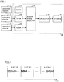
- Fig. 2 is a functional block diagram showing a configuration of data processor 80.
- data processor 80 includes filters 81 to 83, a sensor signal selector 84, a calculator 85, and a storage 86.
- Data processor 80 may be configured to include a not-shown transmitter and to transmit data to the outside of the wind turbine generator.
- Filters 81 to 83 receive detection signals from vibration sensors 71 to 73, respectively, allow passage of a component in a predetermined specific frequency band of the received detection signals, and attenuate components in other frequency bands.
- Data processor 80 may simultaneously process a plurality of signals or process a signal in a specific channel. Therefore, sensor signal selector 84 is configured to be able to receive a plurality of signal inputs from the vibration sensors and select a signal to be used.
- Data processor 80 includes a central processing unit as calculator 85 and a read only memory (ROM) which stores a processing program and a random access memory (RAM) which temporarily stores data as storage 86, and further includes an input and output port for input and output of various signals (none of which is shown).
- Data processor 80 receives a detection value from each of vibration sensors 71 to 73, processes data, and analyzes vibration by using a method which will be described later in accordance with a program stored in the ROM. Processing performed by data processor 80 is not limited to processing by software, and the processing can also be performed by dedicated hardware (an electronic circuit).
- the condition monitoring apparatus may be configured such that processed vibration measurement data is transmitted to an external server (not shown) and the server analyzes vibration.
- vibration data processor 80 Since a characteristic spectrum of vibration of rotary equipment (vibration of a gear or vibration of a shaft) included in vibration data is varied with a rotation speed, data processor 80 detects variation in rotation speed by detecting variation in spectrum.
- Data processor 80 uses obtained information on variation in speed to modify (resample) a time axis of vibration data and to correct the vibration data to be identical to vibration data in rotation at a constant speed.
- vibration data collected while a rotation speed is varied can be subjected to accurate analysis of a spectrum similarly to data collected while a speed is constant.
- storage 86 stores a plurality of results obtained from a plurality of divided data strings (slots), respectively, resulting from division of a data string obtained by sampling at a regular time interval of signals from sensors 71 to 73 provided in equipment.
- Calculator 85 estimates a plurality of rotation speeds corresponding to the plurality of divided data strings from the plurality of results accumulated in storage 86, respectively, corrects the plurality of divided data strings based on the plurality of rotation speeds, respectively, and generates a corrected data string by combining the plurality of corrected divided data strings.
- a vibration sensor is adopted as sensors 71 to 73 is shown, a sensor which detects sound or acoustic emission may be adopted.
- the plurality of results are a plurality of frequency spectra corresponding to the plurality of divided data strings, respectively.
- Calculator 85 estimates, based on an evaluation value Y (shown in an expression (1) later) indicating a similarity in frequency spectrum between a first divided data string (a slot S(i)) and a second divided data string (a slot S(i+1)) among the plurality of divided data strings, a rotation speed during a period in which the second divided data string was obtained.
- the evaluation value indicating the similarity is an inner product of two frequency spectra.
- calculator 85 analyzes an abnormal condition of the equipment by processing the corrected data string ( Fig. 7 , ST7).
- the equipment monitored by the condition monitoring apparatus is a wind turbine generator.
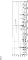
- Fig. 3 is a diagram for illustrating a divided slot of vibration data.
- data processor 80 divides vibration data into certain time segments (slots S(1) to S(n)).
- a length of a slot is set as appropriate so as to satisfy a frequency resolution and a time resolution necessary for FFT processing for a short period of time in each slot.
- a time length of a slot is desirably not longer than one tenth of a period of variation in rotation speed.
- Data processor 80 performs FFT processing on a data string in each of slots S(0) to S(n).
- the frequency spectrum obtained at this time is denoted as F(i)(f), where i is an integer from 0 to n.
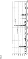
- Fig. 4 is a diagram showing one example of a spectrum in frequency analysis processing performed in an ith slot S(i) and an i+1th slot S(i+1).
- F(i)(f) represents a spectrum in the ith slot (a slot (i))
- F(i+1)(f) represents a spectrum in the i+1th slot (a slot (i+1)).
- the ordinate represents intensity (power) and the abscissa represents a frequency.
- spectrum F(i+1)(f) is shown as being slightly offset in a direction of the ordinate.
- Data processor 80 compares spectra obtained in successive time slots S(i) and S(i+1) and calculates a scaling factor for a frequency axis such that they best match with each other.
- An inner product of spectrum F(i)(f) and spectrum F(i+1)(f) is calculated.
- An inner product value Y is shown in an expression (1) below.
- Inner product value Y represents a similarity between them.
- Y(a, b) represents a sum of products (an inner product) of a spectrum for each frequency in a slot a and a spectrum for each frequency in a slot b, and ⁇ calculation means calculation of a total sum of products of spectra in adjacent slots in connection with a discrete frequency f.
- Y i , i + 1 ⁇ F i f ⁇ F i + 1 f
- a similarity may be evaluated by dividing each of the two spectra by an absolute value or an autocorrelation value C(i) of a vector to find a correlation coefficient CORR.
- Autocorrelation value C(i) and correlation coefficient CORR(i) are shown in expressions (2) to (4) below.
- sqrt represents calculation of a square root.
- C i sqrt ⁇ F i f ⁇ F i f
- Data processor 80 uses such a correlation value of a spectrum to find a rate of variation (a scaling factor ⁇ for a frequency) in rotation speed.
- Fig. 5 is a diagram for illustrating processing applied to a spectrum in the i+1th slot.
- F(i+1)( ⁇ f) represents a spectrum which is ⁇ -fold of spectrum F(i+1)(f) in the direction of the frequency axis.
- ⁇ at which Y(i, i+1, ⁇ ) shown in an expression (5) below or CORR(i+1, ⁇ ) shown in an expression (6) is largest is calculated by varying ⁇ , for example, in increments or decrements of 0.01.
- Y(a, b, c) represents a sum of products (an inner product) of a spectrum for each frequency (f1, f2, f3, ...) in slot a and a spectrum for each c-fold frequency (f1 ⁇ c, f2 ⁇ c, f3 ⁇ c, ...) in slot b.
- a value of ⁇ at which largest inner product value Y is obtained is calculated and denoted as ⁇ (i+1).
- ⁇ (i+1) represents a scaling factor at which data in two slots best match with each other.
- a rate of variation in spectrum in a section of slot S(i+1) with respect to slot S(i) is calculated as ⁇ (i+1). Since a peak frequency is ⁇ (i+1)-fold owing to variation in rotation speed, a rotation speed is calculated as ⁇ (i+1)-fold and a rate of variation in speed between slots is calculated.
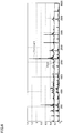
- Fig. 6 is a diagram showing a spectrum when ⁇ at which Y provides a largest value is selected. As shown in Fig. 6 , in a spectrum waveform in which a similarity is highest, spectrum F(i+1)( ⁇ f) to which ⁇ giving largest inner product value Y is applied is observed to match in each peak with spectrum F(i)(f).
- a speed ratio ⁇ (i) from the first slot to the last slot is estimated by calculating, between slots, a value shown in the expression (7).
- a range of frequencies for which an inner product is calculated is set to a region where a characteristic of a spectrum is well exhibited, and a frequency up to approximately ten times as high as a characteristic frequency such as a gear mesh frequency or a shaft rotation frequency is included therein.
- a characteristic frequency such as a gear mesh frequency or a shaft rotation frequency
- accuracy in detection of a rate of variation in speed is low.
- a resonance peak not dependent on a rotation speed may appear and may interfere detection of a component which varies with a rotation speed. Therefore, a range of interest of comparison may be selected as appropriate in accordance with a measurement target.
- Fig. 7 is a flowchart for illustrating processing performed by the data processor. Referring to Fig. 7 , initially, in step ST1, data processor 80 sets a variable i to zero as an initial value.
- step ST2 data processor 80 calculates a spectrum F(i)(f) by performing FFT for slot S(i).
- step ST3 data processor 80 compares spectra F(i)(f) and F(i+1)( ⁇ f) with each other obtained in successive time slots, and calculates scaling factor ⁇ for the frequency axis such that they best match with each other. Specifically, as described with reference to Figs. 4 to 6 , spectrum F(i+1)( ⁇ f) in slot S(i+1) is calculated with scaling factor ⁇ for a frequency being varied, and ⁇ at which Y(i, i+1, ⁇ ) given in the expression (5) or CORR(i, i+1, ⁇ ) given in the expression (6) is largest is calculated as ⁇ (i+1).
- Fig. 8 is a diagram of search for ⁇ high in similarity by varying scaling factor ⁇ for a frequency f of spectrum F(i+1) with respect to spectrum F(i)(f).
- ⁇ at which peaks match with each other is defined as ⁇ (i+1).
- a similarity between the ith slot S(i) and the i+1th slot S(i+1) is evaluated and scaling factor ⁇ (i+1) for the frequency in each slot is calculated.
- evaluation may be made with the first slot S(0) being defined as the reference.
- a similarity between each slot S(i+1) and the first slot S(0) may directly be evaluated to calculate scaling factor ⁇ (i+1) for the frequency.
- a calculation method is desirably devised such that a range of search for ⁇ at which a maximum correlation value is attained is limited to a range around ⁇ (i-1) that precedes.
- a correlation value becomes small in this calculation method. Therefore, in the method shown in the flowchart in Fig. 7 , on the premise that correlation between successive slots S(i) and S(i+1) considered to initially be close to each other in pattern is calculated, a range of search for ⁇ is narrowed to ⁇ X% of ⁇ (i-1).
- calculated ⁇ (i) directly represents a rate of variation in speed.
- calculated ⁇ (i) should be converted to a speed ratio to the first slot and then ⁇ '(i) described above should be calculated.
- step ST6 data processor 80 modifies time of data in each slot S(i) based on obtained information on speed ⁇ i and creates data in slot Sr(i) resampled at a regular interval.
- Fig. 9 is a first diagram for illustrating resampling processing.
- Fig. 10 is a second diagram for illustrating resampling processing.
- a rotation speed in slot S(0) being defined as the reference (a ratio 1)
- An input signal data string as a whole is denoted as D(k), where k represents an integer from 0 to M.
- slot S(0) includes u data strings D(0) to D(u-1)
- slot S(1) includes u data strings D(u) to D(2u-1)
- slot S(2) includes u data strings D(2u) to D(3u-1).
- a ratio R of a time interval between pieces of data in slots is as shown in Fig. 9 .
- Original data of a resampled data number is sequentially placed into data Dr so that a resampled data string is created.
- Correspondence between original data D(k) and resampled data Dr(j) is as shown in Fig. 10 . Since resultant data string Dr(j) is continuous data, processing such as FFT can be performed without any problem.
- Fig. 11 is a conceptual diagram showing a data string D(k) in slot S(1) shown in Fig. 9 .
- Fig. 12 is a conceptual diagram showing data string D(k) in slot S(1) and a resampled data string Dr(j) as being superimposed on each other.
- original data string D(k) is sampled regularly at a sampling interval T.
- some of data is thinned by resampling (when a condition of ⁇ (1) > 1 is satisfied).
- a sampling interval is shorter. Consequently, as described with reference to Fig. 10 , D(1029) in original data string D(k) is excluded. Therefore, data identical in data number k are placed in Dr(1027) to Dr(1028) such as D(1027) to D(1028), whereas data of which data number k is added by one such as D(1030) is placed in Dr(1029).
- data is interpolated as appropriate. For example, as data which is lacking, any data that precedes or follows may be copied and placed or a value calculated by averaging data that precedes and follows may be placed.
- step ST7 entire data Dr(j) in slots Sr(1) to Sr(n) constituted of resampled data are subjected to FFT to analyze a vibration spectrum, and processing in the flowchart ends.
- FFT frequency peak
- it can be expected that a frequency peak is obtained more clearly than in FFT on data before resampling.
- Frequency analysis including resampling processing described in the present embodiment is effective when vibration generated by rotary equipment is sufficiently large relative to background noise.
- vibration generated at a constant frequency such as inverter noise or resonance of a component (vibration at a natural frequency) is dominant, evaluation of a similarity does not go well and followability becomes poor. Therefore, in a wind turbine generator, the data processing method disclosed in the present embodiment is desirably applied to a mechanical component which rotates at a constant rotation speed ratio and is relatively large in vibration such as a gearbox or a generator.
- data in slot S(i) to slot S(i+1) may linearly be interpolated by regarding all data as linearly varying from speed ⁇ (i) to ⁇ (i+1) or may be varied in fine steps at an interval of one severalth of a slot interval.
- Resampling processing may be performed on a waveform resulting from envelope processing of vibration data. Even a vibration waveform of which characteristic is less likely to appear in raw vibration data may exhibit its characteristic in a spectrum of an envelope waveform subjected to envelope processing, and processing for detecting a similarity may be facilitated. In such a case, sensitivity in detection of variation in frequency can be improved.
- condition monitoring apparatus is applicable to any apparatus including a rotor of which rotation is varied.
- processing for correcting data is performed in a monitoring apparatus in a nacelle of a wind turbine generator is shown, data may be transferred in connection with the outside and the processing may be performed in an external analyzer.
Landscapes
- Engineering & Computer Science (AREA)
- Chemical & Material Sciences (AREA)
- Life Sciences & Earth Sciences (AREA)
- Sustainable Development (AREA)
- Sustainable Energy (AREA)
- Combustion & Propulsion (AREA)
- Mechanical Engineering (AREA)
- General Engineering & Computer Science (AREA)
- General Physics & Mathematics (AREA)
- Physics & Mathematics (AREA)
- Testing Of Devices, Machine Parts, Or Other Structures Thereof (AREA)
- Measurement Of Mechanical Vibrations Or Ultrasonic Waves (AREA)
- Wind Motors (AREA)
Abstract
Description
- This invention relates to a condition monitoring apparatus and particularly to a condition monitoring apparatus which monitors a condition of a rotor.
- A monitoring apparatus which obtains data representing a condition of equipment such as vibration data or temperature data for diagnosis of a failure of various types of rotating equipment has been known. For example, in diagnosing an abnormality condition of equipment or facilities by measuring vibration of a rotary portion, a monitoring person determines occurrence of an abnormal condition based on tendency of increase in feature value (an effective value, a kurtosis, a peak value, or a crest factor) extracted from vibration data obtained by the monitoring apparatus. In order to estimate a cause of occurrence of an abnormal condition, a technique to analyze a frequency of vibration data is employed.
- Japanese Patent Laying-Open No.
2015-34776 - PTL 1: Japanese Patent Laying-Open No.
2015-34776 - A condition monitoring system (CMS) which measures vibration of a mechanism such as a bearing of a main shaft or a gearbox with a vibration sensor and monitors a condition of the mechanism in a wind turbine generator has been known.
- Since a rotation speed of a wind turbine is varied due to variation in wind speed or wind direction, a frequency of vibration to be analyzed is varied also in a condition monitoring system of a wind turbine generator and a frequency spectrum fluctuates. Though variation in rotation speed can be suppressed by controlling operations of the wind turbine, variation to some extent is unavoidable. Data to be used for frequency analysis requires a measurement period not less than several rotations of a target rotating object. Only a short measurement period is required for an object which rotates at a high speed, whereas a measurement period from several seconds to several ten seconds is required for an object which rotates at a low speed. Though variation in rotation speed is ignorable in an example requiring a short measurement period, accuracy in analysis disadvantageously lowers in an example requiring a long measurement period. Therefore, in the example requiring a long measurement period, decrease in measurement period and lowering in frequency resolution have been permitted so as not to aggravate influence by variation in speed.
- Though variation in rotation speed can be detected with the use of a rotation sensor and it can also be corrected by calculation, it is often difficult to additionally provide a rotation sensor for monitoring a condition from a point of view of costs and a space for attachment. In a vibration monitoring apparatus of a wind turbine generator, a vibration spectrum is desirably analyzed without being affected by variation in rotation speed and without using a signal from a rotation sensor as much as possible.
- In the diagnosis method shown in Japanese Patent Laying-Open No.
2015-34776 2015-34776 - This invention was made to solve such problems, and an object thereof is to provide a condition monitoring apparatus capable of accurately analyzing data obtained from a sensor while increase in cost is suppressed and influence by variation in rotation is lessened in monitoring of a condition of equipment including a rotor.
- In summary, this invention is directed to a condition monitoring apparatus which monitors a condition of equipment including a rotor, the condition monitoring apparatus including a storage and a calculator. The storage stores a plurality of results obtained from a plurality of divided data strings, respectively, resulting from division of a data string obtained by sampling at a regular time interval of signals from sensors provided in the equipment. The calculator estimates a plurality of rotation speeds corresponding to the plurality of divided data strings from the plurality of results accumulated in the storage, respectively, corrects the plurality of divided data strings based on the plurality of rotation speeds, respectively, and generates a corrected data string by combining the plurality of corrected divided data strings.
- Preferably, the sensors detect any of vibration, sound, and acoustic emission.
- Preferably, the plurality of results are a plurality of frequency spectra corresponding to the plurality of divided data strings, respectively. The calculator estimates, based on an evaluation value indicating a similarity in frequency spectrum between a first divided data string and a second divided data string among the plurality of divided data strings, a rotation speed during a period in which the second divided data string was obtained.
- More preferably, the evaluation value indicating the similarity is an inner product of two frequency spectra.
- Preferably, the calculator analyzes an abnormal condition of the equipment by processing the corrected data string.
- Preferably, the equipment is a wind turbine generator.
- According to the present invention, since data in which influence by variation in rotation has been lessened is generated from data obtained from sensors, rotary equipment can accurately be analyzed.
-
-
Fig. 1 is a diagram schematically showing a construction of a wind turbine generator to which a condition monitoring apparatus according to an embodiment of this invention is applied. -
Fig. 2 is a functional block diagram showing a configuration of a data processor. -
Fig. 3 is a diagram for illustrating a divided slot of vibration data. -
Fig. 4 is a diagram showing one example of a spectrum in frequency analysis processing performed in an ith slot S(i) and an i+1th slot S(i+1). -
Fig. 5 is a diagram for illustrating processing applied to a spectrum in the i+1th slot. -
Fig. 6 is a diagram showing a spectrum when α at which Y provides a largest value is selected. -
Fig. 7 is a flowchart for illustrating processing performed by the data processor. -
Fig. 8 is a diagram of search for α(i+1) high in similarity by varying a scaling factor α for a frequency f of a spectrum F(i+1) with respect to a spectrum F(i)(f). -
Fig. 9 is a first diagram for illustrating resampling processing. -
Fig. 10 is a second diagram for illustrating resampling processing. -
Fig. 11 is a conceptual diagram showing a data string D(k) in a slot S(1) shown inFig. 9 . -
Fig. 12 is a conceptual diagram showing data string D(k) in slot S(1) and a resampled data string Dr(j) as being superimposed on each other. - An embodiment of the present invention will be described below with reference to the drawings. The same or corresponding elements in the drawings below have the same reference characters allotted and detailed description thereof will not be repeated.
-
Fig. 1 is a diagram schematically showing a construction of a wind turbine generator to which a condition monitoring apparatus according to an embodiment of this invention is applied. Referring toFig. 1 , awind turbine generator 10 includes amain shaft 20, ablade 30, agearbox 40, agenerator 50, acontrol board 52, and an electricpower transmission line 54.Wind turbine generator 10 further includes abearing 60 for the main shaft (which is simply referred to as a "bearing" below),vibration sensors 71 to 73, and adata processor 80. Gearbox 40,generator 50,control board 52, bearing 60,vibration sensors 71 to 73, anddata processor 80 are stored in anacelle 90, andnacelle 90 is supported by atower 100. -
Main shaft 20 is inserted innacelle 90, connected to an input shaft ofgearbox 40, and rotatably supported by bearing 60.Main shaft 20 transmits rotation torque generated byblade 30 which receives wind power to the input shaft ofgearbox 40.Blade 30 is provided at a tip end ofmain shaft 20 to convert wind power to rotation torque and to transmit rotation torque tomain shaft 20. -
Bearing 60 is fixed innacelle 90 and rotatably supportsmain shaft 20. Bearing 60 is implemented by a rolling bearing, and implemented, for example, by a spherical roller bearing, a tapered rolling bearing, a cylindrical roller bearing, and a ball bearing. The bearing may be a single-row bearing or a double-row bearing. - Gearbox 40 is provided between
main shaft 20 andgenerator 50, and increases a rotation speed ofmain shaft 20 and outputs the increased rotation speed togenerator 50. By way of example, gearbox 40 is implemented by a step-up gear mechanism including a planetary gear, an intermediate shaft, and a high-speed shaft.Generator 50 is connected to an output shaft ofgearbox 40 and generates electric power by using rotation torque received fromgearbox 40.Generator 50 is implemented, for example, by an induction generator. -
Control board 52 includes an inverter (not shown). The inverter converts electric power generated bygenerator 50 into a system voltage and frequency and outputs the same to electricpower transmission line 54 connected to the system. -
Vibration sensors 71 to 73 are provided ingearbox 40,generator 50, and bearing 60, respectively, and detect vibration thereof and output detected vibration values todata processor 80. -
Fig. 2 is a functional block diagram showing a configuration ofdata processor 80. Referring toFig. 2 ,data processor 80 includesfilters 81 to 83, asensor signal selector 84, acalculator 85, and astorage 86.Data processor 80 may be configured to include a not-shown transmitter and to transmit data to the outside of the wind turbine generator. -
Filters 81 to 83 receive detection signals fromvibration sensors 71 to 73, respectively, allow passage of a component in a predetermined specific frequency band of the received detection signals, and attenuate components in other frequency bands. -
Data processor 80 may simultaneously process a plurality of signals or process a signal in a specific channel. Therefore,sensor signal selector 84 is configured to be able to receive a plurality of signal inputs from the vibration sensors and select a signal to be used. -
Data processor 80 includes a central processing unit ascalculator 85 and a read only memory (ROM) which stores a processing program and a random access memory (RAM) which temporarily stores data asstorage 86, and further includes an input and output port for input and output of various signals (none of which is shown).Data processor 80 receives a detection value from each ofvibration sensors 71 to 73, processes data, and analyzes vibration by using a method which will be described later in accordance with a program stored in the ROM. Processing performed bydata processor 80 is not limited to processing by software, and the processing can also be performed by dedicated hardware (an electronic circuit). The condition monitoring apparatus may be configured such that processed vibration measurement data is transmitted to an external server (not shown) and the server analyzes vibration. - Since a characteristic spectrum of vibration of rotary equipment (vibration of a gear or vibration of a shaft) included in vibration data is varied with a rotation speed,
data processor 80 detects variation in rotation speed by detecting variation in spectrum. -
Data processor 80 uses obtained information on variation in speed to modify (resample) a time axis of vibration data and to correct the vibration data to be identical to vibration data in rotation at a constant speed. Thus, even vibration data collected while a rotation speed is varied can be subjected to accurate analysis of a spectrum similarly to data collected while a speed is constant. - More specifically,
storage 86 stores a plurality of results obtained from a plurality of divided data strings (slots), respectively, resulting from division of a data string obtained by sampling at a regular time interval of signals fromsensors 71 to 73 provided in equipment.Calculator 85 estimates a plurality of rotation speeds corresponding to the plurality of divided data strings from the plurality of results accumulated instorage 86, respectively, corrects the plurality of divided data strings based on the plurality of rotation speeds, respectively, and generates a corrected data string by combining the plurality of corrected divided data strings. Though an example in which a vibration sensor is adopted assensors 71 to 73 is shown, a sensor which detects sound or acoustic emission may be adopted. - Preferably, the plurality of results are a plurality of frequency spectra corresponding to the plurality of divided data strings, respectively.
Calculator 85 estimates, based on an evaluation value Y (shown in an expression (1) later) indicating a similarity in frequency spectrum between a first divided data string (a slot S(i)) and a second divided data string (a slot S(i+1)) among the plurality of divided data strings, a rotation speed during a period in which the second divided data string was obtained. - More preferably, the evaluation value indicating the similarity is an inner product of two frequency spectra.
- Preferably,
calculator 85 analyzes an abnormal condition of the equipment by processing the corrected data string (Fig. 7 , ST7). - Preferably, the equipment monitored by the condition monitoring apparatus is a wind turbine generator.
-
Fig. 3 is a diagram for illustrating a divided slot of vibration data. Referring toFig. 3 ,data processor 80 divides vibration data into certain time segments (slots S(1) to S(n)). - A length of a slot is set as appropriate so as to satisfy a frequency resolution and a time resolution necessary for FFT processing for a short period of time in each slot. For example, a time length of a slot is desirably not longer than one tenth of a period of variation in rotation speed.
-
Data processor 80 performs FFT processing on a data string in each of slots S(0) to S(n). The frequency spectrum obtained at this time is denoted as F(i)(f), where i is an integer from 0 to n. -
Fig. 4 is a diagram showing one example of a spectrum in frequency analysis processing performed in an ith slot S(i) and an i+1th slot S(i+1). InFig. 4 , F(i)(f) represents a spectrum in the ith slot (a slot (i)) and F(i+1)(f) represents a spectrum in the i+1th slot (a slot (i+1)). The ordinate represents intensity (power) and the abscissa represents a frequency. In order to avoid illegibility due to superimposition of waveforms, spectrum F(i+1)(f) is shown as being slightly offset in a direction of the ordinate. - A position of a peak which appears in a spectrum in each slot is varied with variation in rotation speed. It can thus be seen in
Fig. 4 that each spectral peak of spectrum F(i+1)(f) is displaced toward a higher frequency as compared with spectrum F(i)(f). -
Data processor 80 compares spectra obtained in successive time slots S(i) and S(i+1) and calculates a scaling factor for a frequency axis such that they best match with each other. - An inner product of spectrum F(i)(f) and spectrum F(i+1)(f) is calculated. An inner product value Y is shown in an expression (1) below. Inner product value Y represents a similarity between them. Y(a, b) represents a sum of products (an inner product) of a spectrum for each frequency in a slot a and a spectrum for each frequency in a slot b, and ∑ calculation means calculation of a total sum of products of spectra in adjacent slots in connection with a discrete frequency f.

- A similarity may be evaluated by dividing each of the two spectra by an absolute value or an autocorrelation value C(i) of a vector to find a correlation coefficient CORR. Autocorrelation value C(i) and correlation coefficient CORR(i) are shown in expressions (2) to (4) below. sqrt represents calculation of a square root.



- If the rotation speed is constant, a spectrum will substantially be the same. Therefore, both of inner product value Y and correlation coefficient CORR(i, i+1) (similarity) are close to 1. If a rotation speed is varied and a spectrum is varied between slots, a similarity will be lowered.
-
Data processor 80 uses such a correlation value of a spectrum to find a rate of variation (a scaling factor α for a frequency) in rotation speed. -
Fig. 5 is a diagram for illustrating processing applied to a spectrum in the i+1th slot. InFig. 5 , spectrum data is shifted in a direction of a frequency axis with a scaling factor for a frequency being set to α and with α being adjusted, for example, within a range of α = 0.95 to 1.05 (corresponding to ±5%). F(i+1)(αf) represents a spectrum which is α-fold of spectrum F(i+1)(f) in the direction of the frequency axis. - α at which Y(i, i+1, α) shown in an expression (5) below or CORR(i+1, α) shown in an expression (6) is largest is calculated by varying α, for example, in increments or decrements of 0.01. Y(a, b, c) represents a sum of products (an inner product) of a spectrum for each frequency (f1, f2, f3, ...) in slot a and a spectrum for each c-fold frequency (f1·c, f2·c, f3·c, ...) in slot b.


- A value of α at which largest inner product value Y is obtained is calculated and denoted as α(i+1). α(i+1) represents a scaling factor at which data in two slots best match with each other. A rate of variation in spectrum in a section of slot S(i+1) with respect to slot S(i) is calculated as α(i+1). Since a peak frequency is α(i+1)-fold owing to variation in rotation speed, a rotation speed is calculated as α(i+1)-fold and a rate of variation in speed between slots is calculated.
- As set forth above, by varying a frequency axis by varying α, scaling factor α(i+1) at which inner product value Y of two spectra is largest (two spectra are best superimposed on each other) is calculated.
-
Fig. 6 is a diagram showing a spectrum when α at which Y provides a largest value is selected. As shown inFig. 6 , in a spectrum waveform in which a similarity is highest, spectrum F(i+1)(αf) to which α giving largest inner product value Y is applied is observed to match in each peak with spectrum F(i)(f). - By thus sequentially calculating a rate of variation in speed between adjacent slots until the last slot, a rate of variation in speed from the first slot to the last slot is estimated.
- In processing for calculating a similarity, a maximum value of the following value may be evaluated and calculated with a spectrum in the first slot S(0) being defined as the reference:

- A speed ratio α(i) from the first slot to the last slot is estimated by calculating, between slots, a value shown in the expression (7). By using this result, a rotation speed ωi in each slot can be calculated with a rotation speed ω0 in the first slot being defined as the reference:

- Desirably, a range of frequencies for which an inner product is calculated is set to a region where a characteristic of a spectrum is well exhibited, and a frequency up to approximately ten times as high as a characteristic frequency such as a gear mesh frequency or a shaft rotation frequency is included therein. With only a low-frequency component, accuracy in detection of a rate of variation in speed is low. In a region at a high frequency, a resonance peak not dependent on a rotation speed may appear and may interfere detection of a component which varies with a rotation speed. Therefore, a range of interest of comparison may be selected as appropriate in accordance with a measurement target.
- Thereafter, based on obtained information on a speed, data resampled at a regular interval by modifying time of the data in each slot is created.
-
Fig. 7 is a flowchart for illustrating processing performed by the data processor. Referring toFig. 7 , initially, in step ST1,data processor 80 sets a variable i to zero as an initial value. - In succession, in step ST2,
data processor 80 calculates a spectrum F(i)(f) by performing FFT for slot S(i). - Then, in step ST3,
data processor 80 compares spectra F(i)(f) and F(i+1)(αf) with each other obtained in successive time slots, and calculates scaling factor α for the frequency axis such that they best match with each other. Specifically, as described with reference toFigs. 4 to 6 , spectrum F(i+1)(αf) in slot S(i+1) is calculated with scaling factor α for a frequency being varied, and α at which Y(i, i+1, α) given in the expression (5) or CORR(i, i+1, α) given in the expression (6) is largest is calculated as α(i+1). -
Fig. 8 is a diagram of search for α high in similarity by varying scaling factor α for a frequency f of spectrum F(i+1) with respect to spectrum F(i)(f). InFig. 8 , α at which peaks match with each other is defined as α(i+1). - In the flowchart in
Fig. 7 , a similarity between the ith slot S(i) and the i+1th slot S(i+1) is evaluated and scaling factor α(i+1) for the frequency in each slot is calculated. As described with reference to the expression (7), however, evaluation may be made with the first slot S(0) being defined as the reference. A similarity between each slot S(i+1) and the first slot S(0) may directly be evaluated to calculate scaling factor α(i+1) for the frequency. - With the first slot being defined as the reference, when data in which a value of α(i) is varied gradually from slot S(0) is assumed, a calculation method is desirably devised such that a range of search for α at which a maximum correlation value is attained is limited to a range around α(i-1) that precedes. When a pattern is greatly different between slot S(0) and slot S(i), a correlation value becomes small in this calculation method. Therefore, in the method shown in the flowchart in
Fig. 7 , on the premise that correlation between successive slots S(i) and S(i+1) considered to initially be close to each other in pattern is calculated, a range of search for α is narrowed to ±X% of α(i-1). In this case, since adjacent slots are characterized by their high correlation with each other, variation in speed is better followed. In this case, since calculated α(k) represents a speed ratio between adjacent slots, subsequent processing is performed with the speed ratio being finally converted to a ratio to slot S(0) such as α'(1) = α(0)*α(1). ..., α'(i) = α'(i-1)+α(i), where α(0) = 1. - When calculation is performed between slot S(0) and slot S(i), calculated α(i) directly represents a rate of variation in speed. When calculation between adjacent slots is performed as in the method in
Fig. 7 , however, calculated α(i) should be converted to a speed ratio to the first slot and then α'(i) described above should be calculated. - Referring again to
Fig. 7 ,data processor 80 increments variable i in step ST4, and determines whether or not a condition of i = n is satisfied in step ST5, where n represents a number of the last slot resulting from division inFig. 3 . - While a condition of i < n is satisfied, processing in ST2 to ST4 is repeated. Frequency analysis processing is thus performed with vibration data being divided into certain time segments (slots) (short FFT processing).
- When evaluation of a similarity among slots S(1) to S(n) is completed and α(1) to α(n) are obtained, in step ST6,
data processor 80 modifies time of data in each slot S(i) based on obtained information on speed ωi and creates data in slot Sr(i) resampled at a regular interval. -
Fig. 9 is a first diagram for illustrating resampling processing.Fig. 10 is a second diagram for illustrating resampling processing. - With a rotation speed in slot S(0) being defined as the reference (a ratio 1), scaling factors for a rotation speed in slots S(1) and S(2) are denoted as α(1) and α(2), respectively. Since slot S(0) is defined as the reference, a result of conversion of a sampling interval between slots S(1) and S(2) with the use of speed ratio α is expressed as T1 = T/α(1) and T2 = T/α(2), where T represents a sampling interval.
- An input signal data string as a whole is denoted as D(k), where k represents an integer from 0 to M. This data is divided, for example, into slots S(0) to S(n) each including u data strings, where relation of n = M/u is satisfied.
- Specifically, slot S(0) includes u data strings D(0) to D(u-1), slot S(1) includes u data strings D(u) to D(2u-1), and slot S(2) includes u data strings D(2u) to D(3u-1).
- A ratio R of a time interval between pieces of data in slots is as shown in
Fig. 9 . A sequence of integers is created by rounding off a cumulative value of these ratios R in each slot, and it is defined as a resampled data number. Since ratio R of a time interval in slot S(0) is 1, the cumulative value increases in increments of 1 such as 1, 2, 3, 4, ... Ratio R of a time interval in slot S(1) is 1/α(1). Therefore, if a condition of 1/α(1) = 1.1 is assumed, the cumulative value increases in increments of 1.1 such as 1027.3, 1028.4, 1029.5, 1030.6, ... A data number expressed as an integer is 1, 2, 3, 4, ... for slot S(0), and as 1027, 1028, 1030, 1031, ... for slot S(2). - Original data of a resampled data number is sequentially placed into data Dr so that a resampled data string is created. Correspondence between original data D(k) and resampled data Dr(j) is as shown in
Fig. 10 . Since resultant data string Dr(j) is continuous data, processing such as FFT can be performed without any problem. -
Fig. 11 is a conceptual diagram showing a data string D(k) in slot S(1) shown inFig. 9 .Fig. 12 is a conceptual diagram showing data string D(k) in slot S(1) and a resampled data string Dr(j) as being superimposed on each other. - As shown in
Fig. 11 , original data string D(k) is sampled regularly at a sampling interval T. In a section from data D(1027) to D(1030), some of data is thinned by resampling (when a condition of α(1) > 1 is satisfied). As shown inFig. 12 , after resampling, a sampling interval is shorter. Consequently, as described with reference toFig. 10 , D(1029) in original data string D(k) is excluded. Therefore, data identical in data number k are placed in Dr(1027) to Dr(1028) such as D(1027) to D(1028), whereas data of which data number k is added by one such as D(1030) is placed in Dr(1029). When a condition of α(i) < 1 is satisfied, instead of thinning out data, data is interpolated as appropriate. For example, as data which is lacking, any data that precedes or follows may be copied and placed or a value calculated by averaging data that precedes and follows may be placed. - Since data of which fluctuation has been corrected can thus be generated from data obtained in an environment where the rotation speed fluctuates, accuracy in analysis of a frequency peak in frequency analysis is improved.
- Referring again to
Fig. 7 , in step ST7, entire data Dr(j) in slots Sr(1) to Sr(n) constituted of resampled data are subjected to FFT to analyze a vibration spectrum, and processing in the flowchart ends. In this case, it can be expected that a frequency peak is obtained more clearly than in FFT on data before resampling. In particular, it is effective for an example in which a wind speed is low and a rotation speed is low, because the number of pieces of data Dr(j) as a whole should be increased by using data collected for a long period of time for improving accuracy. - Frequency analysis including resampling processing described in the present embodiment is effective when vibration generated by rotary equipment is sufficiently large relative to background noise. When vibration generated at a constant frequency such as inverter noise or resonance of a component (vibration at a natural frequency) is dominant, evaluation of a similarity does not go well and followability becomes poor. Therefore, in a wind turbine generator, the data processing method disclosed in the present embodiment is desirably applied to a mechanical component which rotates at a constant rotation speed ratio and is relatively large in vibration such as a gearbox or a generator.
- When data collected while a rotation speed is varied is subjected to processing for varying a sampling interval so as to follow variation in rotation speed, ideally, data sampled at the same interval of a rotation angle in spite of variation in rotation speed can be obtained. When a vibration component is generated in synchronization with rotation, a peak frequency obtained in FFT is varied with variation in rotation speed. When resampling processing is performed, however, a peak frequency remains the same without varying. On the other hand, a component at a constant frequency not affected by a rotation speed such as electric noise represented by inverter noise or mechanical resonance is varied to a fluctuating component when it is resampled. Since a frequency spectrum of inverter noise or the like irrelevant to rotation is blurred, analysis of a vibration component further in synchronization with rotation is advantageously facilitated.
- When a variation in rotation speed is great, improvement as below may be made. Specifically, a series of processes for estimating variation in speed is performed to find an average speed ratio in slot S(i). When a width of a slot is large or variation in speed between adjacent slots is great, however, the speed ratio may vary discontinuously and stepwise between slots. In such a case, discontinuous variation can be made gentler by (1) calculation of a speed ratio by interpolation between slots as appropriate or (2) decrease in width of a slot for which a speed ratio is calculated. Specifically, data in slot S(i) to slot S(i+1) may linearly be interpolated by regarding all data as linearly varying from speed ω(i) to ω(i+1) or may be varied in fine steps at an interval of one severalth of a slot interval.
- Resampling processing may be performed on a waveform resulting from envelope processing of vibration data. Even a vibration waveform of which characteristic is less likely to appear in raw vibration data may exhibit its characteristic in a spectrum of an envelope waveform subjected to envelope processing, and processing for detecting a similarity may be facilitated. In such a case, sensitivity in detection of variation in frequency can be improved.
- Though a wind turbine generator is exemplified in the description above as a monitoring target to which a condition monitoring apparatus is applied, limitation thereto is not intended. The condition monitoring apparatus described above is applicable to any apparatus including a rotor of which rotation is varied. Though an example in which processing for correcting data is performed in a monitoring apparatus in a nacelle of a wind turbine generator is shown, data may be transferred in connection with the outside and the processing may be performed in an external analyzer.
- It should be understood that the embodiment disclosed herein is illustrative and non-restrictive in every respect. The scope of the present invention is defined by the terms of the claims rather than the description of the embodiment above and is intended to include any modifications within the scope and meaning equivalent to the terms of the claims.
- 10 wind turbine generator; 20 main shaft; 30 blade; 40 gearbox; 50 generator; 52 control board; 54 electric power transmission line; 60 bearing; 71 to 73 vibration sensor; 80 data processor; 81 to 83 filter; 84 sensor signal selector; 85 calculator; 86 storage; 90 nacelle; 100 tower
Claims (6)
- A condition monitoring apparatus which monitors a condition of equipment including a rotor, the condition monitoring apparatus comprising:a storage configured to store a plurality of results obtained from a plurality of divided data strings, respectively, resulting from division of a data string obtained by sampling at a regular time interval of signals from sensors provided in the equipment; anda calculator configured to estimate a plurality of rotation speeds corresponding to the plurality of divided data strings from the plurality of results accumulated in the storage, respectively, correct the plurality of divided data strings based on the plurality of rotation speeds, respectively, and generate a corrected data string by combining the plurality of corrected divided data strings.
- The condition monitoring apparatus according to claim 1, wherein
the sensors detect any of vibration, sound, and acoustic emission. - The condition monitoring apparatus according to claim 1 or 2, wherein
the plurality of results are a plurality of frequency spectra corresponding to the plurality of divided data strings, respectively, and
the calculator estimates, based on an evaluation value indicating a similarity in frequency spectrum between a first divided data string and a second divided data string among the plurality of divided data strings, a rotation speed during a period in which the second divided data string was obtained. - The condition monitoring apparatus according to claim 3, wherein
the evaluation value indicating the similarity is an inner product of two frequency spectra. - The condition monitoring apparatus according to any one of claims 1 to 4, wherein
the calculator is configured to analyze an abnormal condition of the equipment by processing the corrected data string. - The condition monitoring apparatus according to any one of claims 1 to 5, wherein
the equipment is a wind turbine generator.
Applications Claiming Priority (2)
| Application Number | Priority Date | Filing Date | Title |
|---|---|---|---|
| JP2016168909A JP6665062B2 (en) | 2016-08-31 | 2016-08-31 | Condition monitoring device |
| PCT/JP2017/027959 WO2018043009A1 (en) | 2016-08-31 | 2017-08-02 | State monitoring device |
Publications (3)
| Publication Number | Publication Date |
|---|---|
| EP3508834A1 true EP3508834A1 (en) | 2019-07-10 |
| EP3508834A4 EP3508834A4 (en) | 2020-04-15 |
| EP3508834B1 EP3508834B1 (en) | 2022-09-14 |
Family
ID=61301208
Family Applications (1)
| Application Number | Title | Priority Date | Filing Date |
|---|---|---|---|
| EP17846018.4A Active EP3508834B1 (en) | 2016-08-31 | 2017-08-02 | Condition monitoring apparatus |
Country Status (5)
| Country | Link |
|---|---|
| US (1) | US10895243B2 (en) |
| EP (1) | EP3508834B1 (en) |
| JP (1) | JP6665062B2 (en) |
| CN (1) | CN109642855B (en) |
| WO (1) | WO2018043009A1 (en) |
Cited By (1)
| Publication number | Priority date | Publication date | Assignee | Title |
|---|---|---|---|---|
| EP4368959A4 (en) * | 2021-07-07 | 2024-11-13 | NSK Ltd. | STATE MONITORING APPARATUS FOR MECHANICAL APPARATUS, WIND POWER GENERATION APPARATUS, STATE MONITORING METHOD, AND PROGRAM |
Families Citing this family (23)
| Publication number | Priority date | Publication date | Assignee | Title |
|---|---|---|---|---|
| JP7164468B2 (en) * | 2018-07-13 | 2022-11-01 | Ntn株式会社 | Condition monitoring device and condition monitoring system |
| AT522260B1 (en) * | 2019-03-11 | 2021-08-15 | Avl List Gmbh | Method and control device for controlling a speed |
| KR102101824B1 (en) * | 2019-05-03 | 2020-04-20 | 한국콘베어공업주식회사 | Method for estimating length of roller chain using friction sound |
| US11486483B1 (en) * | 2019-07-08 | 2022-11-01 | Gpms International, Inc. | Condition monitoring for components of a gearbox |
| DE112020003362T5 (en) * | 2019-07-12 | 2022-06-02 | Ntn Corporation | DATA ACQUISITION DEVICE |
| WO2021049008A1 (en) * | 2019-09-13 | 2021-03-18 | 三菱電機エンジニアリング株式会社 | Vibration detection device, vibration detection method, and abnormality determination system |
| JP2021196220A (en) * | 2020-06-11 | 2021-12-27 | ボッシュ株式会社 | Processing device and control method of the processing device |
| CN113847197B (en) * | 2020-06-28 | 2023-02-28 | 北京金风科创风电设备有限公司 | Wind generating set and rotation avoiding speed control method and device thereof |
| JP7415850B2 (en) * | 2020-08-24 | 2024-01-17 | 株式会社明電舎 | Structural abnormality diagnosis device and structural abnormality diagnosis method |
| JP7528677B2 (en) * | 2020-09-28 | 2024-08-06 | セイコーエプソン株式会社 | Signal processing method, signal processing device, and monitoring system |
| US11708815B2 (en) | 2021-02-08 | 2023-07-25 | General Electronic Company | System and method for controlling a wind turbine |
| US11774324B2 (en) | 2021-03-12 | 2023-10-03 | General Electric Renovables Espana, S.L. | System and method for detecting actual slip in a coupling of a rotary shaft |
| US11913429B2 (en) | 2021-04-29 | 2024-02-27 | General Electric Renovables Espana, S.L. | System and method for slip detection and surface health monitoring in a slip coupling of a rotary shaft |
| CN113217303B (en) * | 2021-06-21 | 2022-06-24 | 华能新能源股份有限公司 | Self-adaptive resonance rotating speed control method based on life evaluation |
| JP7830899B2 (en) * | 2021-11-19 | 2026-03-17 | 日本精工株式会社 | Method for monitoring the condition of machinery and equipment, condition monitoring system, condition monitoring device, wind power generation device, and program |
| JP2023009580A (en) * | 2021-07-07 | 2023-01-20 | 日本精工株式会社 | State monitoring device of rolling bearing, wind turbine generator, state monitoring method, and program |
| CN114184343B (en) * | 2021-11-29 | 2023-10-17 | 安徽科技学院 | Gear characteristic research is with easy dismouting around self-protection's impact test equipment |
| CN115144171B (en) * | 2022-07-06 | 2024-09-24 | 青岛睿发工程咨询服务合伙企业(有限合伙) | Rotating machinery vibration signal normalization method under variable rotation speed working condition |
| JP2025024375A (en) * | 2023-08-07 | 2025-02-20 | 株式会社日立製作所 | Automatic driving equipment status monitoring device, automatic driving equipment status monitoring method |
| CN117249050B (en) * | 2023-10-19 | 2026-02-27 | 中科星图瑞云科技有限公司 | A wind turbine operation health monitoring and management system |
| CN120427101A (en) * | 2024-02-02 | 2025-08-05 | 皓博科技股份有限公司 | Rotating machinery abnormality feature detection system and method |
| KR102803184B1 (en) * | 2024-10-05 | 2025-05-07 | 주식회사 에스씨솔루션글로벌 | Leak sensing system |
| CN120684367B (en) * | 2025-06-16 | 2025-12-02 | 安徽中科昊音智能科技有限公司 | Wavelet multi-scale fan blade defect detection method based on rotation speed synchronous time difference correction |
Family Cites Families (22)
| Publication number | Priority date | Publication date | Assignee | Title |
|---|---|---|---|---|
| WO2006030786A1 (en) * | 2004-09-13 | 2006-03-23 | Nsk Ltd. | Abnormality diagnosis device and abnormality diagnosis method |
| JP3780299B1 (en) * | 2005-06-24 | 2006-05-31 | 独立行政法人科学技術振興機構 | Diagnostic method for target equipment, computer program, and apparatus for diagnosing target equipment |
| US7844453B2 (en) * | 2006-05-12 | 2010-11-30 | Qnx Software Systems Co. | Robust noise estimation |
| EP4033212A1 (en) * | 2008-12-22 | 2022-07-27 | S.P.M. Instrument AB | An analysis system |
| EA021908B1 (en) * | 2008-12-22 | 2015-09-30 | С.П.М. Инструмент Аб | Method, apparatus and computer readable medium for analysing the condition of a machine having a rotating part |
| TWI538394B (en) * | 2009-04-10 | 2016-06-11 | 杜比實驗室特許公司 | Obtaining a desired non-zero phase shift using forward-backward filtering |
| WO2010128928A1 (en) * | 2009-05-05 | 2010-11-11 | S.P.M. Instrument Ab | An apparatus and a method for analysing the vibration of a machine having a rotating part |
| US9008997B2 (en) * | 2009-10-26 | 2015-04-14 | Fluke Corporation | System and method for vibration analysis and phase analysis of vibration waveforms using dynamic statistical averaging of tachometer data to accurately calculate rotational speed |
| JP5067979B2 (en) * | 2010-06-01 | 2012-11-07 | 三菱電機エンジニアリング株式会社 | Bearing diagnostic device |
| US8994359B2 (en) * | 2011-08-29 | 2015-03-31 | General Electric Company | Fault detection based on current signature analysis for a generator |
| US20130096848A1 (en) * | 2011-10-13 | 2013-04-18 | Charles Terrance Hatch | Methods and systems for automatic rolling-element bearing fault detection |
| EA027344B1 (en) * | 2012-01-30 | 2017-07-31 | С.П.М. Инструмент Аб | Apparatus and method for analysing the condition of a machine having a rotating part |
| US10359473B2 (en) * | 2012-05-29 | 2019-07-23 | Nutech Ventures | Detecting faults in turbine generators |
| US9671442B2 (en) * | 2012-11-30 | 2017-06-06 | General Electric Company | System and method for detecting a grid event |
| US9829502B2 (en) | 2013-05-30 | 2017-11-28 | Lockheed Martin Corporation | Mechanisms for deriving an accurate timing signal from a noisy waveform |
| CN103353396B (en) * | 2013-06-24 | 2015-11-25 | 西安交通大学 | Based on the Fault Diagnosis of Gear Case method without markers phase demodulating in short-term |
| JP6120720B2 (en) | 2013-08-09 | 2017-04-26 | 株式会社神戸製鋼所 | Frequency analysis method and diagnostic method for rotating equipment using this frequency analysis method |
| JP2015175828A (en) * | 2014-03-18 | 2015-10-05 | Ntn株式会社 | State monitoring device for rolling device and wind power generation facility including the same |
| CN103884502B (en) * | 2014-04-02 | 2018-01-05 | 清华大学 | A kind of variable speed leeward power generator planetary gear system method for diagnosing faults |
| GB2535167B (en) * | 2015-02-09 | 2017-03-29 | 24 Acoustics Ltd | Audio signal processing apparatus, client device, system and method |
| CN105806613A (en) * | 2015-11-24 | 2016-07-27 | 国网内蒙古东部电力有限公司电力科学研究院 | Planetary gear case fault diagnosis method based on order complexity |
| JP6530780B2 (en) * | 2017-05-16 | 2019-06-12 | ファナック株式会社 | Display device and processing system for oscillating cutting |
-
2016
- 2016-08-31 JP JP2016168909A patent/JP6665062B2/en active Active
-
2017
- 2017-08-02 WO PCT/JP2017/027959 patent/WO2018043009A1/en not_active Ceased
- 2017-08-02 CN CN201780052961.9A patent/CN109642855B/en active Active
- 2017-08-02 EP EP17846018.4A patent/EP3508834B1/en active Active
- 2017-08-02 US US16/328,163 patent/US10895243B2/en active Active
Cited By (1)
| Publication number | Priority date | Publication date | Assignee | Title |
|---|---|---|---|---|
| EP4368959A4 (en) * | 2021-07-07 | 2024-11-13 | NSK Ltd. | STATE MONITORING APPARATUS FOR MECHANICAL APPARATUS, WIND POWER GENERATION APPARATUS, STATE MONITORING METHOD, AND PROGRAM |
Also Published As
| Publication number | Publication date |
|---|---|
| WO2018043009A1 (en) | 2018-03-08 |
| EP3508834B1 (en) | 2022-09-14 |
| JP6665062B2 (en) | 2020-03-13 |
| US20190195192A1 (en) | 2019-06-27 |
| CN109642855B (en) | 2021-12-17 |
| US10895243B2 (en) | 2021-01-19 |
| CN109642855A (en) | 2019-04-16 |
| JP2018036124A (en) | 2018-03-08 |
| EP3508834A4 (en) | 2020-04-15 |
Similar Documents
| Publication | Publication Date | Title |
|---|---|---|
| EP3508834B1 (en) | Condition monitoring apparatus | |
| US11519821B2 (en) | Detecting faults in wind turbines | |
| US8066486B2 (en) | Method and apparatus for vibration-based automatic condition monitoring of a wind turbine | |
| Urbanek et al. | Comparison of amplitude-based and phase-based method for speed tracking in application to wind turbines | |
| Wang et al. | Rolling element bearing fault diagnosis via fault characteristic order (FCO) analysis | |
| EP3611489B1 (en) | State monitoring device, state monitoring system, and state monitoring method | |
| Sawalhi et al. | Gear parameter identification in a wind turbine gearbox using vibration signals | |
| US12007310B2 (en) | State monitoring device and state monitoring system | |
| JPH09113416A (en) | Rolling bearing damage diagnosis method | |
| Guo et al. | Tooth root crack detection of planet and sun gears based on resonance demodulation and vibration separation | |
| CN112105907B (en) | Method and apparatus for monitoring a gear system | |
| CN104266747A (en) | Fault diagnosis method based on vibration signal order analysis | |
| EP4234927B1 (en) | Condition monitoring system and wind turbine comprising same | |
| US20190078974A1 (en) | Process and device for the supervision of the kinematics of an epicyclic planetary gearbox | |
| EP2730898A1 (en) | Bearing, housing including a set of bearings, associated method and computer program | |
| JP2019100761A (en) | Removal method of electromagnetic vibrational component, diagnostic method of rotary machine, and diagnostic device of rotary machine | |
| Peng et al. | Speed estimation in planetary gearboxes: A method for reducing impulsive noise | |
| EP4357611A1 (en) | Load estimating device for rolling bearing, control device for mechanical device provided with rolling bearing, load estimating method, and program | |
| Yang et al. | Autocorrelation-based time synchronous averaging for condition monitoring of gearboxes in wind turbines | |
| JP7830899B2 (en) | Method for monitoring the condition of machinery and equipment, condition monitoring system, condition monitoring device, wind power generation device, and program | |
| CN120587258A (en) | A monitoring and diagnosis system for rolling mill reducers based on multi-source information fusion | |
| WO2023282028A1 (en) | State monitoring apparatus for mechanical apparatus, wind power generation apparatus, state monitoring method, and program | |
| JP7169084B2 (en) | Condition monitoring device and condition monitoring system | |
| CN113029553A (en) | Method, system and device for extracting rotating speed information of gearbox shaft and storage medium | |
| Randall et al. | Determining the speed of a variable speed wind turbine from the vibration response |
Legal Events
| Date | Code | Title | Description |
|---|---|---|---|
| STAA | Information on the status of an ep patent application or granted ep patent |
Free format text: STATUS: THE INTERNATIONAL PUBLICATION HAS BEEN MADE |
|
| PUAI | Public reference made under article 153(3) epc to a published international application that has entered the european phase |
Free format text: ORIGINAL CODE: 0009012 |
|
| STAA | Information on the status of an ep patent application or granted ep patent |
Free format text: STATUS: REQUEST FOR EXAMINATION WAS MADE |
|
| 17P | Request for examination filed |
Effective date: 20190329 |
|
| AK | Designated contracting states |
Kind code of ref document: A1 Designated state(s): AL AT BE BG CH CY CZ DE DK EE ES FI FR GB GR HR HU IE IS IT LI LT LU LV MC MK MT NL NO PL PT RO RS SE SI SK SM TR |
|
| AX | Request for extension of the european patent |
Extension state: BA ME |
|
| DAV | Request for validation of the european patent (deleted) | ||
| DAX | Request for extension of the european patent (deleted) | ||
| A4 | Supplementary search report drawn up and despatched |
Effective date: 20200317 |
|
| RIC1 | Information provided on ipc code assigned before grant |
Ipc: F03D 17/00 20160101ALI20200311BHEP Ipc: G01P 3/44 20060101ALI20200311BHEP Ipc: G01M 99/00 20110101AFI20200311BHEP Ipc: F03D 1/06 20060101ALI20200311BHEP Ipc: G01M 13/04 20190101ALI20200311BHEP Ipc: G01M 13/02 20190101ALI20200311BHEP Ipc: G01M 7/00 20060101ALI20200311BHEP |
|
| STAA | Information on the status of an ep patent application or granted ep patent |
Free format text: STATUS: EXAMINATION IS IN PROGRESS |
|
| 17Q | First examination report despatched |
Effective date: 20210322 |
|
| GRAP | Despatch of communication of intention to grant a patent |
Free format text: ORIGINAL CODE: EPIDOSNIGR1 |
|
| STAA | Information on the status of an ep patent application or granted ep patent |
Free format text: STATUS: GRANT OF PATENT IS INTENDED |
|
| INTG | Intention to grant announced |
Effective date: 20220317 |
|
| GRAS | Grant fee paid |
Free format text: ORIGINAL CODE: EPIDOSNIGR3 |
|
| GRAA | (expected) grant |
Free format text: ORIGINAL CODE: 0009210 |
|
| STAA | Information on the status of an ep patent application or granted ep patent |
Free format text: STATUS: THE PATENT HAS BEEN GRANTED |
|
| AK | Designated contracting states |
Kind code of ref document: B1 Designated state(s): AL AT BE BG CH CY CZ DE DK EE ES FI FR GB GR HR HU IE IS IT LI LT LU LV MC MK MT NL NO PL PT RO RS SE SI SK SM TR |
|
| REG | Reference to a national code |
Ref country code: GB Ref legal event code: FG4D |
|
| REG | Reference to a national code |
Ref country code: CH Ref legal event code: EP |
|
| REG | Reference to a national code |
Ref country code: DE Ref legal event code: R096 Ref document number: 602017061861 Country of ref document: DE |
|
| REG | Reference to a national code |
Ref country code: IE Ref legal event code: FG4D |
|
| REG | Reference to a national code |
Ref country code: AT Ref legal event code: REF Ref document number: 1518979 Country of ref document: AT Kind code of ref document: T Effective date: 20221015 |
|
| REG | Reference to a national code |
Ref country code: LT Ref legal event code: MG9D |
|
| REG | Reference to a national code |
Ref country code: NL Ref legal event code: MP Effective date: 20220914 |
|
| PG25 | Lapsed in a contracting state [announced via postgrant information from national office to epo] |
Ref country code: SE Free format text: LAPSE BECAUSE OF FAILURE TO SUBMIT A TRANSLATION OF THE DESCRIPTION OR TO PAY THE FEE WITHIN THE PRESCRIBED TIME-LIMIT Effective date: 20220914 Ref country code: RS Free format text: LAPSE BECAUSE OF FAILURE TO SUBMIT A TRANSLATION OF THE DESCRIPTION OR TO PAY THE FEE WITHIN THE PRESCRIBED TIME-LIMIT Effective date: 20220914 Ref country code: NO Free format text: LAPSE BECAUSE OF FAILURE TO SUBMIT A TRANSLATION OF THE DESCRIPTION OR TO PAY THE FEE WITHIN THE PRESCRIBED TIME-LIMIT Effective date: 20221214 Ref country code: LV Free format text: LAPSE BECAUSE OF FAILURE TO SUBMIT A TRANSLATION OF THE DESCRIPTION OR TO PAY THE FEE WITHIN THE PRESCRIBED TIME-LIMIT Effective date: 20220914 Ref country code: LT Free format text: LAPSE BECAUSE OF FAILURE TO SUBMIT A TRANSLATION OF THE DESCRIPTION OR TO PAY THE FEE WITHIN THE PRESCRIBED TIME-LIMIT Effective date: 20220914 Ref country code: FI Free format text: LAPSE BECAUSE OF FAILURE TO SUBMIT A TRANSLATION OF THE DESCRIPTION OR TO PAY THE FEE WITHIN THE PRESCRIBED TIME-LIMIT Effective date: 20220914 |
|
| REG | Reference to a national code |
Ref country code: AT Ref legal event code: MK05 Ref document number: 1518979 Country of ref document: AT Kind code of ref document: T Effective date: 20220914 |
|
| PG25 | Lapsed in a contracting state [announced via postgrant information from national office to epo] |
Ref country code: HR Free format text: LAPSE BECAUSE OF FAILURE TO SUBMIT A TRANSLATION OF THE DESCRIPTION OR TO PAY THE FEE WITHIN THE PRESCRIBED TIME-LIMIT Effective date: 20220914 Ref country code: GR Free format text: LAPSE BECAUSE OF FAILURE TO SUBMIT A TRANSLATION OF THE DESCRIPTION OR TO PAY THE FEE WITHIN THE PRESCRIBED TIME-LIMIT Effective date: 20221215 |
|
| PG25 | Lapsed in a contracting state [announced via postgrant information from national office to epo] |
Ref country code: SM Free format text: LAPSE BECAUSE OF FAILURE TO SUBMIT A TRANSLATION OF THE DESCRIPTION OR TO PAY THE FEE WITHIN THE PRESCRIBED TIME-LIMIT Effective date: 20220914 Ref country code: RO Free format text: LAPSE BECAUSE OF FAILURE TO SUBMIT A TRANSLATION OF THE DESCRIPTION OR TO PAY THE FEE WITHIN THE PRESCRIBED TIME-LIMIT Effective date: 20220914 Ref country code: PT Free format text: LAPSE BECAUSE OF FAILURE TO SUBMIT A TRANSLATION OF THE DESCRIPTION OR TO PAY THE FEE WITHIN THE PRESCRIBED TIME-LIMIT Effective date: 20230116 Ref country code: ES Free format text: LAPSE BECAUSE OF FAILURE TO SUBMIT A TRANSLATION OF THE DESCRIPTION OR TO PAY THE FEE WITHIN THE PRESCRIBED TIME-LIMIT Effective date: 20220914 Ref country code: CZ Free format text: LAPSE BECAUSE OF FAILURE TO SUBMIT A TRANSLATION OF THE DESCRIPTION OR TO PAY THE FEE WITHIN THE PRESCRIBED TIME-LIMIT Effective date: 20220914 Ref country code: AT Free format text: LAPSE BECAUSE OF FAILURE TO SUBMIT A TRANSLATION OF THE DESCRIPTION OR TO PAY THE FEE WITHIN THE PRESCRIBED TIME-LIMIT Effective date: 20220914 |
|
| PG25 | Lapsed in a contracting state [announced via postgrant information from national office to epo] |
Ref country code: SK Free format text: LAPSE BECAUSE OF FAILURE TO SUBMIT A TRANSLATION OF THE DESCRIPTION OR TO PAY THE FEE WITHIN THE PRESCRIBED TIME-LIMIT Effective date: 20220914 Ref country code: PL Free format text: LAPSE BECAUSE OF FAILURE TO SUBMIT A TRANSLATION OF THE DESCRIPTION OR TO PAY THE FEE WITHIN THE PRESCRIBED TIME-LIMIT Effective date: 20220914 Ref country code: IS Free format text: LAPSE BECAUSE OF FAILURE TO SUBMIT A TRANSLATION OF THE DESCRIPTION OR TO PAY THE FEE WITHIN THE PRESCRIBED TIME-LIMIT Effective date: 20230114 Ref country code: EE Free format text: LAPSE BECAUSE OF FAILURE TO SUBMIT A TRANSLATION OF THE DESCRIPTION OR TO PAY THE FEE WITHIN THE PRESCRIBED TIME-LIMIT Effective date: 20220914 |
|
| REG | Reference to a national code |
Ref country code: DE Ref legal event code: R097 Ref document number: 602017061861 Country of ref document: DE |
|
| PG25 | Lapsed in a contracting state [announced via postgrant information from national office to epo] |
Ref country code: NL Free format text: LAPSE BECAUSE OF FAILURE TO SUBMIT A TRANSLATION OF THE DESCRIPTION OR TO PAY THE FEE WITHIN THE PRESCRIBED TIME-LIMIT Effective date: 20220914 Ref country code: AL Free format text: LAPSE BECAUSE OF FAILURE TO SUBMIT A TRANSLATION OF THE DESCRIPTION OR TO PAY THE FEE WITHIN THE PRESCRIBED TIME-LIMIT Effective date: 20220914 |
|
| PLBE | No opposition filed within time limit |
Free format text: ORIGINAL CODE: 0009261 |
|
| STAA | Information on the status of an ep patent application or granted ep patent |
Free format text: STATUS: NO OPPOSITION FILED WITHIN TIME LIMIT |
|
| PG25 | Lapsed in a contracting state [announced via postgrant information from national office to epo] |
Ref country code: DK Free format text: LAPSE BECAUSE OF FAILURE TO SUBMIT A TRANSLATION OF THE DESCRIPTION OR TO PAY THE FEE WITHIN THE PRESCRIBED TIME-LIMIT Effective date: 20220914 |
|
| 26N | No opposition filed |
Effective date: 20230615 |
|
| PG25 | Lapsed in a contracting state [announced via postgrant information from national office to epo] |
Ref country code: SI Free format text: LAPSE BECAUSE OF FAILURE TO SUBMIT A TRANSLATION OF THE DESCRIPTION OR TO PAY THE FEE WITHIN THE PRESCRIBED TIME-LIMIT Effective date: 20220914 |
|
| PG25 | Lapsed in a contracting state [announced via postgrant information from national office to epo] |
Ref country code: MC Free format text: LAPSE BECAUSE OF FAILURE TO SUBMIT A TRANSLATION OF THE DESCRIPTION OR TO PAY THE FEE WITHIN THE PRESCRIBED TIME-LIMIT Effective date: 20220914 |
|
| REG | Reference to a national code |
Ref country code: CH Ref legal event code: PL |
|
| PG25 | Lapsed in a contracting state [announced via postgrant information from national office to epo] |
Ref country code: MC Free format text: LAPSE BECAUSE OF FAILURE TO SUBMIT A TRANSLATION OF THE DESCRIPTION OR TO PAY THE FEE WITHIN THE PRESCRIBED TIME-LIMIT Effective date: 20220914 |
|
| PG25 | Lapsed in a contracting state [announced via postgrant information from national office to epo] |
Ref country code: LU Free format text: LAPSE BECAUSE OF NON-PAYMENT OF DUE FEES Effective date: 20230802 |
|
| GBPC | Gb: european patent ceased through non-payment of renewal fee |
Effective date: 20230802 |
|
| PG25 | Lapsed in a contracting state [announced via postgrant information from national office to epo] |
Ref country code: LU Free format text: LAPSE BECAUSE OF NON-PAYMENT OF DUE FEES Effective date: 20230802 Ref country code: CH Free format text: LAPSE BECAUSE OF NON-PAYMENT OF DUE FEES Effective date: 20230831 |
|
| REG | Reference to a national code |
Ref country code: BE Ref legal event code: MM Effective date: 20230831 |
|
| REG | Reference to a national code |
Ref country code: IE Ref legal event code: MM4A |
|
| PG25 | Lapsed in a contracting state [announced via postgrant information from national office to epo] |
Ref country code: IT Free format text: LAPSE BECAUSE OF FAILURE TO SUBMIT A TRANSLATION OF THE DESCRIPTION OR TO PAY THE FEE WITHIN THE PRESCRIBED TIME-LIMIT Effective date: 20220914 |
|
| PG25 | Lapsed in a contracting state [announced via postgrant information from national office to epo] |
Ref country code: IE Free format text: LAPSE BECAUSE OF NON-PAYMENT OF DUE FEES Effective date: 20230802 |
|
| PG25 | Lapsed in a contracting state [announced via postgrant information from national office to epo] |
Ref country code: GB Free format text: LAPSE BECAUSE OF NON-PAYMENT OF DUE FEES Effective date: 20230802 |
|
| PG25 | Lapsed in a contracting state [announced via postgrant information from national office to epo] |
Ref country code: IE Free format text: LAPSE BECAUSE OF NON-PAYMENT OF DUE FEES Effective date: 20230802 Ref country code: GB Free format text: LAPSE BECAUSE OF NON-PAYMENT OF DUE FEES Effective date: 20230802 |
|
| PG25 | Lapsed in a contracting state [announced via postgrant information from national office to epo] |
Ref country code: BE Free format text: LAPSE BECAUSE OF NON-PAYMENT OF DUE FEES Effective date: 20230831 |
|
| PG25 | Lapsed in a contracting state [announced via postgrant information from national office to epo] |
Ref country code: BG Free format text: LAPSE BECAUSE OF FAILURE TO SUBMIT A TRANSLATION OF THE DESCRIPTION OR TO PAY THE FEE WITHIN THE PRESCRIBED TIME-LIMIT Effective date: 20220914 |
|
| PG25 | Lapsed in a contracting state [announced via postgrant information from national office to epo] |
Ref country code: BG Free format text: LAPSE BECAUSE OF FAILURE TO SUBMIT A TRANSLATION OF THE DESCRIPTION OR TO PAY THE FEE WITHIN THE PRESCRIBED TIME-LIMIT Effective date: 20220914 |
|
| PG25 | Lapsed in a contracting state [announced via postgrant information from national office to epo] |
Ref country code: CY Free format text: LAPSE BECAUSE OF FAILURE TO SUBMIT A TRANSLATION OF THE DESCRIPTION OR TO PAY THE FEE WITHIN THE PRESCRIBED TIME-LIMIT; INVALID AB INITIO Effective date: 20170802 |
|
| PG25 | Lapsed in a contracting state [announced via postgrant information from national office to epo] |
Ref country code: HU Free format text: LAPSE BECAUSE OF FAILURE TO SUBMIT A TRANSLATION OF THE DESCRIPTION OR TO PAY THE FEE WITHIN THE PRESCRIBED TIME-LIMIT; INVALID AB INITIO Effective date: 20170802 |
|
| PGFP | Annual fee paid to national office [announced via postgrant information from national office to epo] |
Ref country code: DE Payment date: 20250702 Year of fee payment: 9 |
|
| PGFP | Annual fee paid to national office [announced via postgrant information from national office to epo] |
Ref country code: FR Payment date: 20250703 Year of fee payment: 9 |
|
| PG25 | Lapsed in a contracting state [announced via postgrant information from national office to epo] |
Ref country code: TR Free format text: LAPSE BECAUSE OF FAILURE TO SUBMIT A TRANSLATION OF THE DESCRIPTION OR TO PAY THE FEE WITHIN THE PRESCRIBED TIME-LIMIT Effective date: 20220914 |