EP3508767A2 - System and method for diagnosing pneumatic control valve online - Google Patents
System and method for diagnosing pneumatic control valve online Download PDFInfo
- Publication number
- EP3508767A2 EP3508767A2 EP17846986.2A EP17846986A EP3508767A2 EP 3508767 A2 EP3508767 A2 EP 3508767A2 EP 17846986 A EP17846986 A EP 17846986A EP 3508767 A2 EP3508767 A2 EP 3508767A2
- Authority
- EP
- European Patent Office
- Prior art keywords
- control valve
- pneumatic control
- online
- data
- server
- Prior art date
- Legal status (The legal status is an assumption and is not a legal conclusion. Google has not performed a legal analysis and makes no representation as to the accuracy of the status listed.)
- Granted
Links
Images




Classifications
-
- F—MECHANICAL ENGINEERING; LIGHTING; HEATING; WEAPONS; BLASTING
- F15—FLUID-PRESSURE ACTUATORS; HYDRAULICS OR PNEUMATICS IN GENERAL
- F15B—SYSTEMS ACTING BY MEANS OF FLUIDS IN GENERAL; FLUID-PRESSURE ACTUATORS, e.g. SERVOMOTORS; DETAILS OF FLUID-PRESSURE SYSTEMS, NOT OTHERWISE PROVIDED FOR
- F15B19/00—Testing; Calibrating; Fault detection or monitoring; Simulation or modelling of fluid-pressure systems or apparatus not otherwise provided for
-
- G—PHYSICS
- G05—CONTROLLING; REGULATING
- G05B—CONTROL OR REGULATING SYSTEMS IN GENERAL; FUNCTIONAL ELEMENTS OF SUCH SYSTEMS; MONITORING OR TESTING ARRANGEMENTS FOR SUCH SYSTEMS OR ELEMENTS
- G05B23/00—Testing or monitoring of control systems or parts thereof
- G05B23/02—Electric testing or monitoring
- G05B23/0205—Electric testing or monitoring by means of a monitoring system capable of detecting and responding to faults
- G05B23/0218—Electric testing or monitoring by means of a monitoring system capable of detecting and responding to faults characterised by the fault detection method dealing with either existing or incipient faults
- G05B23/0221—Preprocessing measurements, e.g. data collection rate adjustment; Standardization of measurements; Time series or signal analysis, e.g. frequency analysis or wavelets; Trustworthiness of measurements; Indexes therefor; Measurements using easily measured parameters to estimate parameters difficult to measure; Virtual sensor creation; De-noising; Sensor fusion; Unconventional preprocessing inherently present in specific fault detection methods like PCA-based methods
-
- F—MECHANICAL ENGINEERING; LIGHTING; HEATING; WEAPONS; BLASTING
- F16—ENGINEERING ELEMENTS AND UNITS; GENERAL MEASURES FOR PRODUCING AND MAINTAINING EFFECTIVE FUNCTIONING OF MACHINES OR INSTALLATIONS; THERMAL INSULATION IN GENERAL
- F16K—VALVES; TAPS; COCKS; ACTUATING-FLOATS; DEVICES FOR VENTING OR AERATING
- F16K37/00—Special means in or on valves or other cut-off apparatus for indicating or recording operation thereof, or for enabling an alarm to be given
- F16K37/0025—Electrical or magnetic means
- F16K37/0041—Electrical or magnetic means for measuring valve parameters
-
- F—MECHANICAL ENGINEERING; LIGHTING; HEATING; WEAPONS; BLASTING
- F15—FLUID-PRESSURE ACTUATORS; HYDRAULICS OR PNEUMATICS IN GENERAL
- F15B—SYSTEMS ACTING BY MEANS OF FLUIDS IN GENERAL; FLUID-PRESSURE ACTUATORS, e.g. SERVOMOTORS; DETAILS OF FLUID-PRESSURE SYSTEMS, NOT OTHERWISE PROVIDED FOR
- F15B19/00—Testing; Calibrating; Fault detection or monitoring; Simulation or modelling of fluid-pressure systems or apparatus not otherwise provided for
- F15B19/005—Fault detection or monitoring
-
- F—MECHANICAL ENGINEERING; LIGHTING; HEATING; WEAPONS; BLASTING
- F16—ENGINEERING ELEMENTS AND UNITS; GENERAL MEASURES FOR PRODUCING AND MAINTAINING EFFECTIVE FUNCTIONING OF MACHINES OR INSTALLATIONS; THERMAL INSULATION IN GENERAL
- F16K—VALVES; TAPS; COCKS; ACTUATING-FLOATS; DEVICES FOR VENTING OR AERATING
- F16K31/00—Actuating devices; Operating means; Releasing devices
- F16K31/12—Actuating devices; Operating means; Releasing devices actuated by fluid
-
- F—MECHANICAL ENGINEERING; LIGHTING; HEATING; WEAPONS; BLASTING
- F16—ENGINEERING ELEMENTS AND UNITS; GENERAL MEASURES FOR PRODUCING AND MAINTAINING EFFECTIVE FUNCTIONING OF MACHINES OR INSTALLATIONS; THERMAL INSULATION IN GENERAL
- F16K—VALVES; TAPS; COCKS; ACTUATING-FLOATS; DEVICES FOR VENTING OR AERATING
- F16K37/00—Special means in or on valves or other cut-off apparatus for indicating or recording operation thereof, or for enabling an alarm to be given
-
- F—MECHANICAL ENGINEERING; LIGHTING; HEATING; WEAPONS; BLASTING
- F16—ENGINEERING ELEMENTS AND UNITS; GENERAL MEASURES FOR PRODUCING AND MAINTAINING EFFECTIVE FUNCTIONING OF MACHINES OR INSTALLATIONS; THERMAL INSULATION IN GENERAL
- F16K—VALVES; TAPS; COCKS; ACTUATING-FLOATS; DEVICES FOR VENTING OR AERATING
- F16K37/00—Special means in or on valves or other cut-off apparatus for indicating or recording operation thereof, or for enabling an alarm to be given
- F16K37/0075—For recording or indicating the functioning of a valve in combination with test equipment
- F16K37/0083—For recording or indicating the functioning of a valve in combination with test equipment by measuring valve parameters
-
- G—PHYSICS
- G01—MEASURING; TESTING
- G01M—TESTING STATIC OR DYNAMIC BALANCE OF MACHINES OR STRUCTURES; TESTING OF STRUCTURES OR APPARATUS, NOT OTHERWISE PROVIDED FOR
- G01M13/00—Testing of machine parts
- G01M13/003—Machine valves
-
- G—PHYSICS
- G05—CONTROLLING; REGULATING
- G05B—CONTROL OR REGULATING SYSTEMS IN GENERAL; FUNCTIONAL ELEMENTS OF SUCH SYSTEMS; MONITORING OR TESTING ARRANGEMENTS FOR SUCH SYSTEMS OR ELEMENTS
- G05B23/00—Testing or monitoring of control systems or parts thereof
- G05B23/02—Electric testing or monitoring
- G05B23/0205—Electric testing or monitoring by means of a monitoring system capable of detecting and responding to faults
- G05B23/0259—Electric testing or monitoring by means of a monitoring system capable of detecting and responding to faults characterized by the response to fault detection
- G05B23/0264—Control of logging system, e.g. decision on which data to store; time-stamping measurements
-
- G—PHYSICS
- G05—CONTROLLING; REGULATING
- G05B—CONTROL OR REGULATING SYSTEMS IN GENERAL; FUNCTIONAL ELEMENTS OF SUCH SYSTEMS; MONITORING OR TESTING ARRANGEMENTS FOR SUCH SYSTEMS OR ELEMENTS
- G05B23/00—Testing or monitoring of control systems or parts thereof
- G05B23/02—Electric testing or monitoring
- G05B23/0205—Electric testing or monitoring by means of a monitoring system capable of detecting and responding to faults
- G05B23/0259—Electric testing or monitoring by means of a monitoring system capable of detecting and responding to faults characterized by the response to fault detection
- G05B23/0267—Fault communication, e.g. human machine interface [HMI]
- G05B23/0272—Presentation of monitored results, e.g. selection of status reports to be displayed; Filtering information to the user
-
- F—MECHANICAL ENGINEERING; LIGHTING; HEATING; WEAPONS; BLASTING
- F15—FLUID-PRESSURE ACTUATORS; HYDRAULICS OR PNEUMATICS IN GENERAL
- F15B—SYSTEMS ACTING BY MEANS OF FLUIDS IN GENERAL; FLUID-PRESSURE ACTUATORS, e.g. SERVOMOTORS; DETAILS OF FLUID-PRESSURE SYSTEMS, NOT OTHERWISE PROVIDED FOR
- F15B2211/00—Circuits for servomotor systems
- F15B2211/80—Other types of control related to particular problems or conditions
- F15B2211/857—Monitoring of fluid pressure systems
-
- F—MECHANICAL ENGINEERING; LIGHTING; HEATING; WEAPONS; BLASTING
- F15—FLUID-PRESSURE ACTUATORS; HYDRAULICS OR PNEUMATICS IN GENERAL
- F15B—SYSTEMS ACTING BY MEANS OF FLUIDS IN GENERAL; FLUID-PRESSURE ACTUATORS, e.g. SERVOMOTORS; DETAILS OF FLUID-PRESSURE SYSTEMS, NOT OTHERWISE PROVIDED FOR
- F15B2211/00—Circuits for servomotor systems
- F15B2211/80—Other types of control related to particular problems or conditions
- F15B2211/87—Detection of failures
-
- G—PHYSICS
- G05—CONTROLLING; REGULATING
- G05B—CONTROL OR REGULATING SYSTEMS IN GENERAL; FUNCTIONAL ELEMENTS OF SUCH SYSTEMS; MONITORING OR TESTING ARRANGEMENTS FOR SUCH SYSTEMS OR ELEMENTS
- G05B2219/00—Program-control systems
- G05B2219/20—Pc systems
- G05B2219/24—Pc safety
- G05B2219/24048—Remote test, monitoring, diagnostic
-
- G—PHYSICS
- G05—CONTROLLING; REGULATING
- G05B—CONTROL OR REGULATING SYSTEMS IN GENERAL; FUNCTIONAL ELEMENTS OF SUCH SYSTEMS; MONITORING OR TESTING ARRANGEMENTS FOR SUCH SYSTEMS OR ELEMENTS
- G05B2219/00—Program-control systems
- G05B2219/30—Nc systems
- G05B2219/33—Director till display
- G05B2219/33284—Remote diagnostic
-
- G—PHYSICS
- G05—CONTROLLING; REGULATING
- G05B—CONTROL OR REGULATING SYSTEMS IN GENERAL; FUNCTIONAL ELEMENTS OF SUCH SYSTEMS; MONITORING OR TESTING ARRANGEMENTS FOR SUCH SYSTEMS OR ELEMENTS
- G05B2219/00—Program-control systems
- G05B2219/30—Nc systems
- G05B2219/33—Director till display
- G05B2219/33326—Analyzer, diagnostic for servovalve
-
- G—PHYSICS
- G05—CONTROLLING; REGULATING
- G05B—CONTROL OR REGULATING SYSTEMS IN GENERAL; FUNCTIONAL ELEMENTS OF SUCH SYSTEMS; MONITORING OR TESTING ARRANGEMENTS FOR SUCH SYSTEMS OR ELEMENTS
- G05B2219/00—Program-control systems
- G05B2219/30—Nc systems
- G05B2219/45—Nc applications
- G05B2219/45006—Valves
Definitions
- the present invention relates to a pneumatic control valve and, more particularly, to a method and system for diagnosing a pneumatic control valve.
- a pneumatic control valve is a device that performs very important role in power plant operation such as rate of flow adjustment, tank level adjustment, and the like in a power plant, and needs to be driven without failure in normal driving of the power plant. Accordingly, in order to maintain a valve state of the pneumatic control valve, maintenance is performed periodically or an important component is replaced for a predetermined period. In addition, when an abnormal state such as a control is not smooth during operation occurs, the power plant is stopped and the state is checked by using a valve diagnosing equipment. Particularly, in the case of an important control value, the power plant should be shut down when an abnormal state occurs. However, if the abnormal state occurred during operation is accurately diagnosed and available to provide information for future progress, it is beneficial economically.
- Patent document 1 Korean Patent Application Publication 2010-0079166 (Online integrated monitoring system for integrity of power generating unit)
- An object of the present invention to solve the problem described above is to provide a system for diagnosing a pneumatic control valve in online that is able to diagnose an abnormality of a target control value by obtaining data from a stem force sensor, a displacement sensor and a pressure sensor mounted on the pneumatic control valve, extracting and transmitting data required for online diagnosis selectively, and that is able to diagnose future progress of the abnormality in real-time.
- Another object of the present invention to solve the problem described above is to provide a method for diagnosing a pneumatic control valve in online that is able to diagnose an abnormality of a target control value by obtaining data from a stem force sensor, a displacement sensor and a pressure sensor mounted on the pneumatic control valve extracting and transmitting data required for online diagnosis selectively, and that is able to diagnose future progress of the abnormality in real-time.
- a system for diagnosing a pneumatic control valve online may include a sensor set including a plurality of sensors, attached to the pneumatic control valve, for measuring a state of the pneumatic control valve; a smart data analyzer for processing a sensor signal acquired in real time from the sensor set and generating pneumatic control valve state information for online automatic diagnosis of the pneumatic control valve; a data server for transmitting, to an online analysis server, the pneumatic control valve state information received in real time from the smart data analyzer and storing the pneumatic control valve state information for a predetermined time period; the online diagnostic server for determining whether the pneumatic control valve is in an abnormal state and generating diagnostic information by comparing the pneumatic control valve state information with pre-stored normal state data of the pneumatic control valve; and a client computer for displaying the diagnostic information received from the online diagnostic server.
- the sensor set may include at least one of: a stem force sensor, attached to a valve stem of the pneumatic control valve, for measuring a stem force; a stem displacement sensor for measuring a stem motion of the pneumatic control valve; and a pressure sensor for measuring an air pressure on a plurality of points of an air supply tube of a control loop that controls the pneumatic control valve.
- the smart data analyzer may transmit a sensor signal including at least one of a stem force signal acquired from the stem force sensor, a stem displacement signal acquired from the stem displacement sensor and a plurality of pressure signals acquired from the pressure sensor to the data server.
- the smart data analyzer may further generate detail analysis data for user detailed analysis for the pneumatic control valve by processing the sensor signal acquired from the sensor set in real time.
- the client computer may receive the detail analysis data via the data server and the online diagnostic server, and include an analysis tool such that a client is able to analyze a state of the pneumatic control valve based on the detail analysis data.
- the data server may transmit the pneumatic control valve state information to the online diagnostic server with a first time interval, and transmit the detail analysis data to the online diagnostic server with a second time interval which is longer than the first time interval.
- the data server may transmit the detail analysis data to the online diagnostic server in response to a request of the client computer.
- the system for diagnosing a pneumatic control valve online may perform a diagnosis for states of a plurality of pneumatic control valves, and include a plurality of sensor sets, a plurality of smart data analyzers and a plurality of data servers corresponding to the plurality of pneumatic control valves.
- a method for diagnosing a pneumatic control valve online may include measuring a state of the pneumatic control valve, by using a sensor set attached to the pneumatic control valve; generating, by a smart data analyzer, pneumatic control valve state information for online automatic diagnosis of the pneumatic control valve by processing a sensor signal acquired in real time from the sensor set; transmitting, by a data server, the pneumatic control valve state information received in real time from the smart data analyzer to an online analysis server, and storing the pneumatic control valve state information for a predetermined time period; generating diagnostic information, by the online diagnostic server, by determining whether the pneumatic control valve is in an abnormal state by comparing the pneumatic control valve state information with pre-stored normal state data of the pneumatic control valve; and displaying, by a client computer, the diagnostic information received from the online diagnostic server.
- the sensor set may include at least one of: a stem force sensor, attached to a valve stem of the pneumatic control valve, for measuring a stem force; a stem displacement sensor for measuring a stem motion of the pneumatic control valve; and a pressure sensor for measuring an air pressure on a plurality of points of an air supply tube of a control loop that controls the pneumatic control valve.
- a storage medium readable by a computer for diagnosing a pneumatic control valve online may include a processor included in the computer to perform: a command for measuring a state of the pneumatic control valve, by using a sensor set attached to the pneumatic control valve; a command for generating, by a smart data analyzer, pneumatic control valve state information for online automatic diagnosis of the pneumatic control valve by processing a sensor signal acquired in real time from the sensor set; a command for transmitting, by a data server, the pneumatic control valve state information received in real time from the smart data analyzer to an online analysis server, and storing the pneumatic control valve state information for a predetermined time period; a command for generating diagnostic information, by the online diagnostic server, by determining whether the pneumatic control valve is in an abnormal state by comparing the pneumatic control valve state information with pre-stored normal state data of the pneumatic control valve; and a command for displaying, by a client computer, the diagnostic information received from the online diagnostic server.
- the disclosed technique may have the following effect. However, this does not mean that a particular embodiment should include all of the following effects or only the following effects, and it is understood that the scope of the disclosed technique is not limited thereto.
- a diagnostic signal of a pneumatic control valve which is important for driving a power plant is obtained in online and transmitted to a remote location in real time, an abnormality of the pneumatic control valve is diagnosed by using the transmitted data, and future progress of the abnormality is predicted in real time, and accordingly, the present invention may contribute to an efficient diagnosis for the pneumatic control valve and prevent a failure.
- first, second, and the like are used for describing various constituent elements, but the constituent elements are not limited by the terms. The terms are used only to discriminate one constituent element from another component.
- a first component may be referred to as a second component, and similarly, the second component may be referred to as the first component without departing from the scope of the present invention.
- a term 'and/or' includes a combination of a plurality of associated disclosed items or any item of the plurality of associated disclosed items.
- the example embodiment of the present invention relates to a system for online diagnosing a pneumatic control valve used in a power generation equipment and the like, and more particularly, to a method and system that diagnoses an abnormality of a target control value by obtaining data from a stem force sensor, a displacement sensor and a pressure sensor mounted on the pneumatic control valve extracting and transmitting data required for online diagnosis selectively, and diagnoses future progress of the abnormality.
- the system for online diagnosing a pneumatic control valve may include a force sensor attached to a valve stem of the pneumatic control valve, a stem displacement sensor, a pressure sensor installed in front and rear ends of a control loop accessory located in an air supply path of the control loop, for example, an I/P converter (current/pressure converter), a position transmitter, a booster, and so on, a smart data analyzer for acquiring data from the sensor and processing, and then selectively extract and transmit data required for online diagnosis, a data server for storing data transmitted from the smart data analyzer for a predetermined time period and transmitting the data required for diagnosis to an online diagnostic server, an online diagnostic server for storing the transmitted data to a central database, and by using this, diagnosing an abnormality of the pneumatic control valve, and evaluating future progress for the abnormal state, and a client computer for receiving data from the online diagnostic server and displaying analysis and diagnosis result in real time and managing system environment.
- a force sensor attached to a valve stem of the pneumatic control valve
- a stem displacement sensor installed in
- FIG. 1 is a configuration diagram of a system for diagnosing a pneumatic control valve online according to an embodiment of the present invention.
- the system for diagnosing a pneumatic control valve online 100 may include a force sensor 120 attached to a valve stem of the pneumatic control valve 110, a stem displacement sensor 121 for measuring a valve stem motion, a plurality of pressure sensors 122 for measuring air supply pressure variation installed on a plurality of points of a control loop 130 that controls the pneumatic control valve, a smart data analyzer 140 connected with the sensors, a data server 150, an online diagnostic server 160 and a client computer 170.
- the control loop for controlling the pneumatic control valve includes accessories such as an air pressure adjuster, a current/pressure converter, a position transmitter, a booster, and the like, and air for driving an air driver is supplied through the control loop.
- the pressure sensor 122 measures air pressure through the air supply path.
- the smart data analyzer 140 collects analogue signals such as force of the valve step, a valve stem displacement, an air supply pressure to the air driver from the sensors 120 to 122 and converts the analogue signals to digital signals, and extracts information required for diagnosing the pneumatic control valve and transmits the information to the data server 150.
- the data server 150 and the online diagnostic server 160 include the function of checking and recovering the system state of the corresponding server, access management, database management, data transmission and reception, data validity check, and the like.
- the data server 150 receives data from the smart data analyzer 140 and stores it in database, and further includes the function of transmitting the data to the online diagnostic server 160 located in remote distance.
- the data server 150 transmits the data required for automatic online diagnosis in an interval such as 1 second, 5 seconds or 10 seconds, and transmits diagnostic signal data required for detailed analysis is transmitted by determining a transmission period or a time according to a network situation, and accordingly, network load may be adjusted.
- the online diagnostic server 160 is further provided with an online diagnostic module having the function of monitoring and diagnosing driving state of the pneumatic control valve 110 using the data transmitted from the data server.
- an online diagnostic module having the function of monitoring and diagnosing driving state of the pneumatic control valve 110 using the data transmitted from the data server.
- the data server 150 is separately provided, but the online diagnostic server 160 may have the function of the data server together.
- a user may access to the online diagnostic server 160 and check the diagnostic result for the target pneumatic control valve, and further provide a tool for detailed diagnosis/analysis and integrated/state monitoring screen in real time.
- the analysis tool collects diagnostic signal data and diagnostic result data from the online diagnostic server according to a user request, and provides a screen required for analysis.
- the integrated/state monitoring screen in real time collects real time measurement data and system state data from a prediction diagnostic server and displays it on a screen.
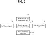
- FIG. 2 is a diagram for describing a function of a smart data analyzer.
- the smart data analyzer is provided with functions such as a system operation and management unit 210, a signal collection and preprocessing unit 220, a self diagnosing unit 230, a state information output unit 240 and a data communication unit 250.
- the system operation and management unit 210 performs configuration information management of smart data analyzer and data transmission and reception between functions and generated data management, and the signal collection and preprocessing unit 220 collects analogue signals from the stem force sensor, the stem displacement sensor and the pressure sensor mounted on the pneumatic control valve, performs digital conversion, acquired signals corrections, transforms to actual physical amount, and performs preprocessing function such as start and termination of stroke, identification data generation, and the like.
- the self diagnosing unit 230 diagnoses a collected signal abnormality, computation load of a system, a memory state, and so on, such that the self diagnosing signal is output to the state information output unit 240.
- the data communication unit 250 transmits information generated in the signal collection and preprocessing unit 220 and self diagnosing unit 230 to the data server (150; FIG. 1 ) periodically with a predetermined interval (e.g., 1 second, 5 seconds, 10 seconds, etc.) using Ethernet communication.
- the smart data analyzer includes 4 channels for collecting force signal, and is available to collect signals up to maximum 20 channels, and mounted with Linux OS such that signal collection and process may be performed automatically.
- FIG. 3 is a diagram for describing a function of a data server.
- the data server 150 shown in FIG. 1 is described in more detail as below.
- a process manager 310, a communication manager 320, a data buffer manager 330, a user log manager 340 and a database manager 350 are also included in the online diagnostic server (160; FIG. 1 ) as well as in the data server (150; FIG. 1 ), and a smart data analyzer data manager 360 and a raw data transmission manager 370 are additionally included in the data server.
- the smart data analyzer data manager 360 processes periodic data and state data, event data, and the like, transmitted from the smart data analyzer and stores it in the database. More preferably, the smart data analyzer data manager 360 enables the data provided from the a plurality of smart data analyzers to be stored in the database without loss. In the case that vast amounts of asynchronous and synchronous waveform data which is periodically transmitted is transmitted to the online diagnostic server in real time, network load is caused, which may cause a network failure, and accordingly, the raw data transmission manager 370 performs the function of transmitting data divisionally while minimizing network bandwidth use amount.
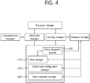
- FIG. 4 is a diagram for describing a function of an online diagnostic server.
- the online diagnostic server (160; FIG. 1 ) is further provided with a data manager 410, an online diagnostic module 420, system/user configuration manager 430 and a client computer manager 440.
- the data manager 410 manages input data required in the online diagnostic module 420.
- the data manager 410 includes data time synchronizing function that groups and adjusts data collection times of all input variables.
- the online diagnostic module 420 generates abnormal state of the target pneumatic control valve and future progress information of the abnormal state using the data transmitted from the data manager 410, and transmits it to database manager.
- the system/user configuration manager 430 manages a user access and authentication, and performs the function of adding, modifying and deleting data related to system configuration in the database.
- the client computer manager 440 performs the function of processing data required for displaying on a screen by a user, and performs the function of forwarding data to a client computer using a network communication.
- FIG. 5 is a configuration diagram of a method and system for diagnosing a pneumatic control valve online according to another embodiment of the present invention. Another embodiment of the present invention is described as below with reference to FIG. 5 .
- a plurality number (510 to 511/520 to 521) of force/displacement/pressure sensor sets 510 and smart data analyzers 520 may be installed and may be used with being connected to a single data server 530. According to processing capacity and network load of the data server, the data server and the network bandwidth may be added and extended.
- the online diagnostic server 540 installed on a remote location may process a plurality of data servers 530 and 531 and client computers 550 to 552.
- the online diagnostic server 540 constructs the database of the online diagnostic server in a separate server, and the online diagnostic module is also constructed in a separate server. Accordingly, each of the processes is separated, and it is available to design a system that may be extended infinitely while a processing performance is guaranteed.
- FIG. 6 is a configuration diagram of a system for diagnosing a pneumatic control valve online according to an embodiment of the present invention
- FIG. 7 is a detailed block diagram of a sensor set.
- a system for diagnosing a pneumatic control valve online according to an embodiment of the present invention is described in more detail with reference to FIG. 6 and FIG. 7 .
- a system for diagnosing a pneumatic control valve online 600 may include a sensor set 610, a smart data analyzer 620, a data server 630, an online diagnostic server 640 and a client computer 650.
- the sensor set 610 may be attached to a pneumatic control valve and include a plurality of sensors for measuring a state of the pneumatic control valve.
- a plurality of sensors may include at least one of a stem force sensor 120, attached to a valve step of the pneumatic control valve, for measuring a stem force, a stem displacement sensor 121 for measuring a stem motion of the pneumatic control valve and a pressure sensor 122 for measuring an air pressure on a plurality of points of an air supply tube of a control loop that controls the pneumatic control valve.
- the smart data analyzer 620 may process a sensor signal acquired in real time from the sensor set 610 and generate pneumatic control valve state information for online automatic diagnosis of the pneumatic control valve.
- the smart data analyzer 620 may transmit a sensor signal including at least one of a stem force signal acquired from the stem force sensor 120, a stem displacement signal acquired from the stem displacement sensor 121 and a plurality of pressure signals acquired from the pressure sensor 122 to the data server 630.
- the smart data analyzer 620 may further generate detail analysis data for user detailed analysis for the pneumatic control valve by processing the sensor signal acquired from the sensor set 610 in real time.
- the generated detail analysis data may be transmitted to at least one of the data server 630, the online diagnostic server 640 and the client computer 650.
- the data server 630 may transmit, to the online analysis server, the pneumatic control valve state information received in real time from the smart data analyzer and storing the pneumatic control valve state information for a predetermined time period. Meanwhile, the data server 630 may further receive detail analysis data from the smart data analyzer 620. In the case of receiving the detail analysis data, the data server 630 may transmit the pneumatic control valve state information to the online diagnostic server 640 with a first time interval, and transmit the detail analysis data to the online diagnostic server 640 with a second time interval which is longer than the first time interval. Alternatively, only in the case that there is a request from the client computer 650, the data server 630 may transmit the detail analysis data to the online diagnostic server 640 or the client computer 650 in response to the request of the client computer.
- the online diagnostic server 640 may determining whether the pneumatic control valve is in an abnormal state and generate diagnostic information by comparing the pneumatic control valve state information with pre-stored normal state data of the pneumatic control valve.
- the client computer 650 may display the diagnostic information received from the online diagnostic server 640 such that a user may identify whether there is abnormality or not. Furthermore, the client computer 650 may receive the detail analysis data via the data server 630 or the online diagnostic server 640, or directly from the smart data analyzer 620, and include an analysis tool such that a client (a user) is able to analyze a state of the pneumatic control valve directly based on the detail analysis data.
- the system for diagnosing a pneumatic control valve online 600 may perform diagnosis for states of a plurality of pneumatic control valves.
- the system for diagnosing a pneumatic control valve online 600 may include a plurality of sensor sets, a plurality of smart data analyzers and a plurality of data servers corresponding to the plurality of pneumatic control valves, respectively.
- a single data server may be assigned to two or more pneumatic control valves and the corresponding sensor set and the corresponding smart data analyzer and an additional data server may be assigned to different pneumatic control valve.
- FIG. 8 is a flowchart of a method for diagnosing a pneumatic control valve online according to an embodiment of the present invention. With reference to FIG. 8 , a method for diagnosing a pneumatic control valve online according to an embodiment of the present invention is described in detail.
- a state of the pneumatic control valve is measured by using a sensor set attached to the pneumatic control valve (step, S810).
- a smart data analyzer generates pneumatic control valve state information for online automatic diagnosis of the pneumatic control valve by processing a sensor signal acquired in real time from the sensor set (step, S820).
- a data server may transmit the pneumatic control valve state information received in real time from the smart data analyzer to an online analysis server and store the pneumatic control valve state information for a predetermined time period (step, S830).
- the online diagnostic server may generate diagnostic information by determining whether the pneumatic control valve is in an abnormal state by comparing the pneumatic control valve state information with pre-stored normal state data of the pneumatic control valve (step, S840).
- a client computer may display the diagnostic information received from the online diagnostic server (step, S850).
- the method for diagnosing a pneumatic control valve online may be further embodied according to the operation of the system for diagnosing a pneumatic control valve online described above.
- the method and system for diagnosing a pneumatic control valve online may be implemented in a medium readable by a computer as codes readable by a computer.
- the medium readable by a computer includes all types of record media in which data readable by a computer system is stored.
- the medium may include ROM (Read Only Memory), RAM (Random Access Memory), magnetic tape, magnetic disk, flash memory, optical data storage device, and the like.
- the medium readable by a computer may be distributed to a computer system connected to a computer network, and stored as codes readable in distributed manner and executed.
Landscapes
- Engineering & Computer Science (AREA)
- General Engineering & Computer Science (AREA)
- Physics & Mathematics (AREA)
- Mechanical Engineering (AREA)
- General Physics & Mathematics (AREA)
- Automation & Control Theory (AREA)
- Fluid Mechanics (AREA)
- Human Computer Interaction (AREA)
- Indication Of The Valve Opening Or Closing Status (AREA)
- Fluid-Driven Valves (AREA)
- Testing And Monitoring For Control Systems (AREA)
Abstract
Description
- The present invention relates to a pneumatic control valve and, more particularly, to a method and system for diagnosing a pneumatic control valve.
- A pneumatic control valve is a device that performs very important role in power plant operation such as rate of flow adjustment, tank level adjustment, and the like in a power plant, and needs to be driven without failure in normal driving of the power plant. Accordingly, in order to maintain a valve state of the pneumatic control valve, maintenance is performed periodically or an important component is replaced for a predetermined period. In addition, when an abnormal state such as a control is not smooth during operation occurs, the power plant is stopped and the state is checked by using a valve diagnosing equipment. Particularly, in the case of an important control value, the power plant should be shut down when an abnormal state occurs. However, if the abnormal state occurred during operation is accurately diagnosed and available to provide information for future progress, it is beneficial economically. However, a system that is able to diagnose in online in a remote location is still not existed. Accordingly, there is a problem that separate equipment for diagnosing a valve is moved to the place where the valve is installed and the valve is directly diagnosed, when it is required, and diagnosis is not available while the valve is driven.
- (Patent document 1) Korean Patent Application Publication
2010-0079166 - An object of the present invention to solve the problem described above is to provide a system for diagnosing a pneumatic control valve in online that is able to diagnose an abnormality of a target control value by obtaining data from a stem force sensor, a displacement sensor and a pressure sensor mounted on the pneumatic control valve, extracting and transmitting data required for online diagnosis selectively, and that is able to diagnose future progress of the abnormality in real-time.
- Another object of the present invention to solve the problem described above is to provide a method for diagnosing a pneumatic control valve in online that is able to diagnose an abnormality of a target control value by obtaining data from a stem force sensor, a displacement sensor and a pressure sensor mounted on the pneumatic control valve extracting and transmitting data required for online diagnosis selectively, and that is able to diagnose future progress of the abnormality in real-time.
- The technical problems to solve in the present invention are not limited thereto, but may be extended in various manners within the scope not departing from the concept and scope of the present invention.
- A system for diagnosing a pneumatic control valve online according to an embodiment of the present invention to attain the technical object may include a sensor set including a plurality of sensors, attached to the pneumatic control valve, for measuring a state of the pneumatic control valve; a smart data analyzer for processing a sensor signal acquired in real time from the sensor set and generating pneumatic control valve state information for online automatic diagnosis of the pneumatic control valve; a data server for transmitting, to an online analysis server, the pneumatic control valve state information received in real time from the smart data analyzer and storing the pneumatic control valve state information for a predetermined time period; the online diagnostic server for determining whether the pneumatic control valve is in an abnormal state and generating diagnostic information by comparing the pneumatic control valve state information with pre-stored normal state data of the pneumatic control valve; and a client computer for displaying the diagnostic information received from the online diagnostic server.
- According to an aspect, the sensor set may include at least one of: a stem force sensor, attached to a valve stem of the pneumatic control valve, for measuring a stem force; a stem displacement sensor for measuring a stem motion of the pneumatic control valve; and a pressure sensor for measuring an air pressure on a plurality of points of an air supply tube of a control loop that controls the pneumatic control valve.
- According to an aspect, the smart data analyzer may transmit a sensor signal including at least one of a stem force signal acquired from the stem force sensor, a stem displacement signal acquired from the stem displacement sensor and a plurality of pressure signals acquired from the pressure sensor to the data server.
- According to an aspect, the smart data analyzer may further generate detail analysis data for user detailed analysis for the pneumatic control valve by processing the sensor signal acquired from the sensor set in real time.
- According to an aspect, the client computer may receive the detail analysis data via the data server and the online diagnostic server, and include an analysis tool such that a client is able to analyze a state of the pneumatic control valve based on the detail analysis data.
- According to an aspect, the data server may transmit the pneumatic control valve state information to the online diagnostic server with a first time interval, and transmit the detail analysis data to the online diagnostic server with a second time interval which is longer than the first time interval.
- According to an aspect, the data server may transmit the detail analysis data to the online diagnostic server in response to a request of the client computer.
- According to an aspect, the system for diagnosing a pneumatic control valve online may perform a diagnosis for states of a plurality of pneumatic control valves, and include a plurality of sensor sets, a plurality of smart data analyzers and a plurality of data servers corresponding to the plurality of pneumatic control valves.
- A method for diagnosing a pneumatic control valve online according to another embodiment of the present invention to attain the technical object may include measuring a state of the pneumatic control valve, by using a sensor set attached to the pneumatic control valve; generating, by a smart data analyzer, pneumatic control valve state information for online automatic diagnosis of the pneumatic control valve by processing a sensor signal acquired in real time from the sensor set; transmitting, by a data server, the pneumatic control valve state information received in real time from the smart data analyzer to an online analysis server, and storing the pneumatic control valve state information for a predetermined time period; generating diagnostic information, by the online diagnostic server, by determining whether the pneumatic control valve is in an abnormal state by comparing the pneumatic control valve state information with pre-stored normal state data of the pneumatic control valve; and displaying, by a client computer, the diagnostic information received from the online diagnostic server.
- According to an aspect, the sensor set may include at least one of: a stem force sensor, attached to a valve stem of the pneumatic control valve, for measuring a stem force; a stem displacement sensor for measuring a stem motion of the pneumatic control valve; and a pressure sensor for measuring an air pressure on a plurality of points of an air supply tube of a control loop that controls the pneumatic control valve.
- A storage medium readable by a computer for diagnosing a pneumatic control valve online according to another embodiment of the present invention to attain the technical object may include a processor included in the computer to perform: a command for measuring a state of the pneumatic control valve, by using a sensor set attached to the pneumatic control valve; a command for generating, by a smart data analyzer, pneumatic control valve state information for online automatic diagnosis of the pneumatic control valve by processing a sensor signal acquired in real time from the sensor set; a command for transmitting, by a data server, the pneumatic control valve state information received in real time from the smart data analyzer to an online analysis server, and storing the pneumatic control valve state information for a predetermined time period; a command for generating diagnostic information, by the online diagnostic server, by determining whether the pneumatic control valve is in an abnormal state by comparing the pneumatic control valve state information with pre-stored normal state data of the pneumatic control valve; and a command for displaying, by a client computer, the diagnostic information received from the online diagnostic server.
- The disclosed technique may have the following effect. However, this does not mean that a particular embodiment should include all of the following effects or only the following effects, and it is understood that the scope of the disclosed technique is not limited thereto.
- According to the method and system for diagnosing a pneumatic control valve online according to an embodiment of the present invention described above, a diagnostic signal of a pneumatic control valve which is important for driving a power plant is obtained in online and transmitted to a remote location in real time, an abnormality of the pneumatic control valve is diagnosed by using the transmitted data, and future progress of the abnormality is predicted in real time, and accordingly, the present invention may contribute to an efficient diagnosis for the pneumatic control valve and prevent a failure.
-
-
FIG. 1 is a configuration diagram of a system for diagnosing a pneumatic control valve online according to an embodiment of the present invention. -
FIG. 2 is a diagram for describing a function of a smart data analyzer. -
FIG. 3 is a diagram for describing a function of a data server. -
FIG. 4 is a diagram for describing a function of an online diagnostic server. -
FIG. 5 is a configuration diagram of a method and system for diagnosing a pneumatic control valve online according to another embodiment of the present invention. -
FIG. 6 is a configuration diagram of a system for diagnosing a pneumatic control valve online according to an embodiment of the present invention. -
FIG. 7 is a detailed block diagram of a sensor set. -
FIG. 8 is a flowchart of a method for diagnosing a pneumatic control valve online according to an embodiment of the present invention. - The present invention may have various modifications and various embodiments and specific embodiments will be illustrated in the drawings and described in detail in the detailed description.
- However, this does not limit the present invention to specific embodiments, and it should be understood that the present invention covers all the modifications, equivalents and replacements included within the idea and technical scope of the present invention.
- Terms including as first, second, and the like are used for describing various constituent elements, but the constituent elements are not limited by the terms. The terms are used only to discriminate one constituent element from another component. For example, a first component may be referred to as a second component, and similarly, the second component may be referred to as the first component without departing from the scope of the present invention. A term 'and/or' includes a combination of a plurality of associated disclosed items or any item of the plurality of associated disclosed items.
- When it is described that a component is "connected to" or "accesses" another component, the component may be directly connected to or access the other component or a third component may be present there between. In contrast, it should be understood that, when it is described that an element is "directly connected to" or "directly access" another element, it is understood that no element is present between the element and another element.
- Terms used in the present application are used only to describe specific embodiments, and are not intended to limit the present invention. A singular form may include a plural form if there is no clearly opposite meaning in the context. In the present application, it should be understood that term "include" or "have" indicates that a feature, a number, a step, an operation, a component, a part or the combination thereof described in the specification is present, but does not exclude a possibility of presence or addition of one or more other features, numbers, steps, operations, components, parts or combinations thereof, in advance.
- Unless it is contrarily defined, all terms used herein including technological or scientific terms have the same meanings as those generally understood by a person with ordinary skill in the art. Terms which are defined in a generally used dictionary should be interpreted to have the same meaning as the meaning in the context of the related art, and are not interpreted as an ideal meaning or excessively formal meanings unless clearly defined in the present application.
- Hereinafter, preferred embodiments of the present invention will be described in detail with reference to the accompanying drawings and in describing the preferred embodiments with reference to the accompanying drawings, the same reference numeral will refer to the same or corresponding component regardless of the reference numeral and a duplicated description thereof will be omitted.
- The example embodiment of the present invention relates to a system for online diagnosing a pneumatic control valve used in a power generation equipment and the like, and more particularly, to a method and system that diagnoses an abnormality of a target control value by obtaining data from a stem force sensor, a displacement sensor and a pressure sensor mounted on the pneumatic control valve extracting and transmitting data required for online diagnosis selectively, and diagnoses future progress of the abnormality.
- The system for online diagnosing a pneumatic control valve according to an embodiment of the present invention to solve the problem described above may include a force sensor attached to a valve stem of the pneumatic control valve, a stem displacement sensor, a pressure sensor installed in front and rear ends of a control loop accessory located in an air supply path of the control loop, for example, an I/P converter (current/pressure converter), a position transmitter, a booster, and so on, a smart data analyzer for acquiring data from the sensor and processing, and then selectively extract and transmit data required for online diagnosis, a data server for storing data transmitted from the smart data analyzer for a predetermined time period and transmitting the data required for diagnosis to an online diagnostic server, an online diagnostic server for storing the transmitted data to a central database, and by using this, diagnosing an abnormality of the pneumatic control valve, and evaluating future progress for the abnormal state, and a client computer for receiving data from the online diagnostic server and displaying analysis and diagnosis result in real time and managing system environment.
-
FIG. 1 is a configuration diagram of a system for diagnosing a pneumatic control valve online according to an embodiment of the present invention. With reference toFIG. 1 , the system for diagnosing a pneumatic control valve online according to an embodiment of the present invention is described in detail. Referring toFIG. 1 , the system for diagnosing a pneumatic control valve online 100 may include aforce sensor 120 attached to a valve stem of thepneumatic control valve 110, astem displacement sensor 121 for measuring a valve stem motion, a plurality ofpressure sensors 122 for measuring air supply pressure variation installed on a plurality of points of acontrol loop 130 that controls the pneumatic control valve, asmart data analyzer 140 connected with the sensors, adata server 150, an onlinediagnostic server 160 and aclient computer 170. The control loop for controlling the pneumatic control valve includes accessories such as an air pressure adjuster, a current/pressure converter, a position transmitter, a booster, and the like, and air for driving an air driver is supplied through the control loop. Thepressure sensor 122 measures air pressure through the air supply path. - The
smart data analyzer 140 collects analogue signals such as force of the valve step, a valve stem displacement, an air supply pressure to the air driver from thesensors 120 to 122 and converts the analogue signals to digital signals, and extracts information required for diagnosing the pneumatic control valve and transmits the information to thedata server 150. Thedata server 150 and the onlinediagnostic server 160 include the function of checking and recovering the system state of the corresponding server, access management, database management, data transmission and reception, data validity check, and the like. - The
data server 150 receives data from thesmart data analyzer 140 and stores it in database, and further includes the function of transmitting the data to the onlinediagnostic server 160 located in remote distance. Thedata server 150 transmits the data required for automatic online diagnosis in an interval such as 1 second, 5 seconds or 10 seconds, and transmits diagnostic signal data required for detailed analysis is transmitted by determining a transmission period or a time according to a network situation, and accordingly, network load may be adjusted. - The online
diagnostic server 160 is further provided with an online diagnostic module having the function of monitoring and diagnosing driving state of thepneumatic control valve 110 using the data transmitted from the data server. In the case that network capacity is enough or the installation position of the online diagnostic server is not far from the target pneumatic control valve, thedata server 150 is separately provided, but the onlinediagnostic server 160 may have the function of the data server together. - A user may access to the online
diagnostic server 160 and check the diagnostic result for the target pneumatic control valve, and further provide a tool for detailed diagnosis/analysis and integrated/state monitoring screen in real time. The analysis tool collects diagnostic signal data and diagnostic result data from the online diagnostic server according to a user request, and provides a screen required for analysis. The integrated/state monitoring screen in real time collects real time measurement data and system state data from a prediction diagnostic server and displays it on a screen. -
FIG. 2 is a diagram for describing a function of a smart data analyzer. Referring toFIG. 2 , the smart data analyzer shown inFIG. 1 is described in more detail as below. The smart data analyzer is provided with functions such as a system operation andmanagement unit 210, a signal collection andpreprocessing unit 220, aself diagnosing unit 230, a stateinformation output unit 240 and adata communication unit 250. - The system operation and
management unit 210 performs configuration information management of smart data analyzer and data transmission and reception between functions and generated data management, and the signal collection andpreprocessing unit 220 collects analogue signals from the stem force sensor, the stem displacement sensor and the pressure sensor mounted on the pneumatic control valve, performs digital conversion, acquired signals corrections, transforms to actual physical amount, and performs preprocessing function such as start and termination of stroke, identification data generation, and the like. Theself diagnosing unit 230 diagnoses a collected signal abnormality, computation load of a system, a memory state, and so on, such that the self diagnosing signal is output to the stateinformation output unit 240. Thedata communication unit 250 transmits information generated in the signal collection andpreprocessing unit 220 andself diagnosing unit 230 to the data server (150;FIG. 1 ) periodically with a predetermined interval (e.g., 1 second, 5 seconds, 10 seconds, etc.) using Ethernet communication. The smart data analyzer includes 4 channels for collecting force signal, and is available to collect signals up to maximum 20 channels, and mounted with Linux OS such that signal collection and process may be performed automatically. -
FIG. 3 is a diagram for describing a function of a data server. Referring toFIG. 3 , thedata server 150 shown inFIG. 1 is described in more detail as below. Aprocess manager 310, acommunication manager 320, adata buffer manager 330, auser log manager 340 and adatabase manager 350 are also included in the online diagnostic server (160;FIG. 1 ) as well as in the data server (150;FIG. 1 ), and a smart dataanalyzer data manager 360 and a rawdata transmission manager 370 are additionally included in the data server. - The smart data
analyzer data manager 360 processes periodic data and state data, event data, and the like, transmitted from the smart data analyzer and stores it in the database. More preferably, the smart dataanalyzer data manager 360 enables the data provided from the a plurality of smart data analyzers to be stored in the database without loss. In the case that vast amounts of asynchronous and synchronous waveform data which is periodically transmitted is transmitted to the online diagnostic server in real time, network load is caused, which may cause a network failure, and accordingly, the rawdata transmission manager 370 performs the function of transmitting data divisionally while minimizing network bandwidth use amount. -
FIG. 4 is a diagram for describing a function of an online diagnostic server. Referring toFIG. 4 , the online diagnostic server (160;FIG. 1 ) is further provided with adata manager 410, an onlinediagnostic module 420, system/user configuration manager 430 and aclient computer manager 440. Thedata manager 410 manages input data required in the onlinediagnostic module 420. And, since the data transmitted from the data server may be transmitted asynchronously owing to a sensor or collection path difference, thedata manager 410 includes data time synchronizing function that groups and adjusts data collection times of all input variables. The onlinediagnostic module 420 generates abnormal state of the target pneumatic control valve and future progress information of the abnormal state using the data transmitted from thedata manager 410, and transmits it to database manager. The system/user configuration manager 430 manages a user access and authentication, and performs the function of adding, modifying and deleting data related to system configuration in the database. Theclient computer manager 440 performs the function of processing data required for displaying on a screen by a user, and performs the function of forwarding data to a client computer using a network communication. -
FIG. 5 is a configuration diagram of a method and system for diagnosing a pneumatic control valve online according to another embodiment of the present invention. Another embodiment of the present invention is described as below with reference toFIG. 5 . A plurality number (510 to 511/520 to 521) of force/displacement/pressure sensor sets 510 and smart data analyzers 520 may be installed and may be used with being connected to asingle data server 530. According to processing capacity and network load of the data server, the data server and the network bandwidth may be added and extended. The onlinediagnostic server 540 installed on a remote location may process a plurality ofdata servers client computers 550 to 552. In addition, considering extendibility, the onlinediagnostic server 540 constructs the database of the online diagnostic server in a separate server, and the online diagnostic module is also constructed in a separate server. Accordingly, each of the processes is separated, and it is available to design a system that may be extended infinitely while a processing performance is guaranteed. -
FIG. 6 is a configuration diagram of a system for diagnosing a pneumatic control valve online according to an embodiment of the present invention, andFIG. 7 is a detailed block diagram of a sensor set. Hereinafter, a system for diagnosing a pneumatic control valve online according to an embodiment of the present invention is described in more detail with reference toFIG. 6 andFIG. 7 . - As shown in
FIG. 6 , a system for diagnosing a pneumatic control valve online 600 according to an embodiment of the present invention may include asensor set 610, asmart data analyzer 620, adata server 630, an onlinediagnostic server 640 and aclient computer 650. - The sensor set 610 may be attached to a pneumatic control valve and include a plurality of sensors for measuring a state of the pneumatic control valve. Such a plurality of sensors may include at least one of a
stem force sensor 120, attached to a valve step of the pneumatic control valve, for measuring a stem force, astem displacement sensor 121 for measuring a stem motion of the pneumatic control valve and apressure sensor 122 for measuring an air pressure on a plurality of points of an air supply tube of a control loop that controls the pneumatic control valve. - The
smart data analyzer 620 may process a sensor signal acquired in real time from the sensor set 610 and generate pneumatic control valve state information for online automatic diagnosis of the pneumatic control valve. - Meanwhile, the
smart data analyzer 620 may transmit a sensor signal including at least one of a stem force signal acquired from thestem force sensor 120, a stem displacement signal acquired from thestem displacement sensor 121 and a plurality of pressure signals acquired from thepressure sensor 122 to thedata server 630. - According to an aspect, the
smart data analyzer 620 may further generate detail analysis data for user detailed analysis for the pneumatic control valve by processing the sensor signal acquired from the sensor set 610 in real time. In addition, the generated detail analysis data may be transmitted to at least one of thedata server 630, the onlinediagnostic server 640 and theclient computer 650. - The
data server 630 may transmit, to the online analysis server, the pneumatic control valve state information received in real time from the smart data analyzer and storing the pneumatic control valve state information for a predetermined time period. Meanwhile, thedata server 630 may further receive detail analysis data from thesmart data analyzer 620. In the case of receiving the detail analysis data, thedata server 630 may transmit the pneumatic control valve state information to the onlinediagnostic server 640 with a first time interval, and transmit the detail analysis data to the onlinediagnostic server 640 with a second time interval which is longer than the first time interval. Alternatively, only in the case that there is a request from theclient computer 650, thedata server 630 may transmit the detail analysis data to the onlinediagnostic server 640 or theclient computer 650 in response to the request of the client computer. - The online
diagnostic server 640 may determining whether the pneumatic control valve is in an abnormal state and generate diagnostic information by comparing the pneumatic control valve state information with pre-stored normal state data of the pneumatic control valve. - The
client computer 650 may display the diagnostic information received from the onlinediagnostic server 640 such that a user may identify whether there is abnormality or not. Furthermore, theclient computer 650 may receive the detail analysis data via thedata server 630 or the onlinediagnostic server 640, or directly from thesmart data analyzer 620, and include an analysis tool such that a client (a user) is able to analyze a state of the pneumatic control valve directly based on the detail analysis data. - Meanwhile, referring to
FIG. 6 , a single of the sensor set 610, thesmart data analyzer 620 and thedata server 630 are shown, but the system for diagnosing a pneumatic control valve online 600 according to an embodiment of the present invention may perform diagnosis for states of a plurality of pneumatic control valves. In this case, the system for diagnosing a pneumatic control valve online 600 may include a plurality of sensor sets, a plurality of smart data analyzers and a plurality of data servers corresponding to the plurality of pneumatic control valves, respectively. Alternatively, a single data server may be assigned to two or more pneumatic control valves and the corresponding sensor set and the corresponding smart data analyzer and an additional data server may be assigned to different pneumatic control valve. -
FIG. 8 is a flowchart of a method for diagnosing a pneumatic control valve online according to an embodiment of the present invention. With reference toFIG. 8 , a method for diagnosing a pneumatic control valve online according to an embodiment of the present invention is described in detail. - As shown in
FIG. 8 , a state of the pneumatic control valve is measured by using a sensor set attached to the pneumatic control valve (step, S810). Later, a smart data analyzer generates pneumatic control valve state information for online automatic diagnosis of the pneumatic control valve by processing a sensor signal acquired in real time from the sensor set (step, S820). A data server may transmit the pneumatic control valve state information received in real time from the smart data analyzer to an online analysis server and store the pneumatic control valve state information for a predetermined time period (step, S830). The online diagnostic server may generate diagnostic information by determining whether the pneumatic control valve is in an abnormal state by comparing the pneumatic control valve state information with pre-stored normal state data of the pneumatic control valve (step, S840). Next, a client computer may display the diagnostic information received from the online diagnostic server (step, S850). - The method for diagnosing a pneumatic control valve online according to an embodiment of the present invention may be further embodied according to the operation of the system for diagnosing a pneumatic control valve online described above.
- The method and system for diagnosing a pneumatic control valve online according to an example embodiment of the present invention may be implemented in a medium readable by a computer as codes readable by a computer. The medium readable by a computer includes all types of record media in which data readable by a computer system is stored. For example, the medium may include ROM (Read Only Memory), RAM (Random Access Memory), magnetic tape, magnetic disk, flash memory, optical data storage device, and the like. In addition, the medium readable by a computer may be distributed to a computer system connected to a computer network, and stored as codes readable in distributed manner and executed.
- So far, the present invention is described with reference to drawings and embodiments. However, it is understood that the scope of the present invention is not limited to the drawings and the embodiments, and those skilled in the art may modify and change the present invention in various ways within the scope not departing from the concept and the scope of the present invention written in the following claims.
-
- 100: method and system for diagnosing a pneumatic control valve online
- 110: pneumatic control valve 120: step force sensor
- 121: stem displacement sensor 122: control loop pressure sensors
- 130: control loop 140: smart data analyzer
- 150: data server 160: online diagnostic server
- 170: client computer
- 210: system operation and management unit 220: signal collection and preprocessing unit
- 230: self diagnosing unit 240: state information output unit
- 250: data communication unit
- 310: process manager 320: communication manager
- 330: data buffer manager 340: user log manager
- 350: database manager
- 360: smart data analyzer data manager
- 370: raw data transmission manager
- 410: data manager 420: online diagnostic module
- 430: system/user configuration manager 440: client computer manager
- 510, 511: force/displacement/pressure sensor set 520, 521: smart data analyzer
- 530, 531: data server 540: online diagnostic server
- 550∼552: client computer
- 600: system for diagnosing a pneumatic control valve online
- 610: sensor set 620: smart data analyzer
- 630: data server 640: online diagnostic server
- 650: client computer
Claims (11)
- A system for diagnosing a pneumatic control valve online, comprising:a sensor set including a plurality of sensors, attached to the pneumatic control valve, for measuring a state of the pneumatic control valve;a smart data analyzer for processing a sensor signal acquired in real time from the sensor set and generating pneumatic control valve state information for online automatic diagnosis of the pneumatic control valve;a data server for transmitting, to an online analysis server, the pneumatic control valve state information received in real time from the smart data analyzer and storing the pneumatic control valve state information for a predetermined time period;the online diagnostic server for determining whether the pneumatic control valve is in an abnormal state and generating diagnostic information by comparing the pneumatic control valve state information with pre-stored normal state data of the pneumatic control valve; anda client computer for displaying the diagnostic information received from the online diagnostic server.
- The system for diagnosing a pneumatic control valve online of claim 1, wherein the sensor set includes at least one of:a stem force sensor, attached to a valve stem of the pneumatic control valve, for measuring a stem force;a stem displacement sensor for measuring a stem motion of the pneumatic control valve; anda pressure sensor for measuring an air pressure on a plurality of points of an air supply tube of a control loop that controls the pneumatic control valve.
- The system for diagnosing a pneumatic control valve online of claim 2, wherein the smart data analyzer transmits a sensor signal including at least one of a stem force signal acquired from the stem force sensor, a stem displacement signal acquired from the stem displacement sensor and a plurality of pressure signals acquired from the pressure sensor to the data server.
- The system for diagnosing a pneumatic control valve online of claim 1, wherein the smart data analyzer further generates detail analysis data for user detailed analysis for the pneumatic control valve by processing the sensor signal acquired from the sensor set in real time.
- The system for diagnosing a pneumatic control valve online of claim 4, wherein the client computer receives the detail analysis data via the data server and the online diagnostic server, and includes an analysis tool such that a client is able to analyze a state of the pneumatic control valve based on the detail analysis data.
- The system for diagnosing a pneumatic control valve online of claim 4, wherein the data server transmits the pneumatic control valve state information to the online diagnostic server with a first time interval, and transmits the detail analysis data to the online diagnostic server with a second time interval which is longer than the first time interval.
- The system for diagnosing a pneumatic control valve online of claim 4, wherein the data server transmits the detail analysis data to the online diagnostic server in response to a request of the client computer.
- The system for diagnosing a pneumatic control valve online of claim 1, wherein the system for diagnosing a pneumatic control valve online performs a diagnosis for states of a plurality of pneumatic control valves, and includes:
a plurality of sensor sets, a plurality of smart data analyzers and a plurality of data servers corresponding to the plurality of pneumatic control valves. - A method for diagnosing a pneumatic control valve online, comprising:measuring a state of the pneumatic control valve, by using a sensor set attached to the pneumatic control valve;generating, by a smart data analyzer, pneumatic control valve state information for online automatic diagnosis of the pneumatic control valve by processing a sensor signal acquired in real time from the sensor set;transmitting, by a data server, the pneumatic control valve state information received in real time from the smart data analyzer to an online analysis server, and storing the pneumatic control valve state information for a predetermined time period;generating diagnostic information, by the online diagnostic server, by determining whether the pneumatic control valve is in an abnormal state by comparing the pneumatic control valve state information with pre-stored normal state data of the pneumatic control valve; anddisplaying, by a client computer, the diagnostic information received from the online diagnostic server.
- The method for diagnosing a pneumatic control valve online of claim 9, wherein the sensor set includes at least one of:a stem force sensor, attached to a valve step of the pneumatic control valve, for measuring a stem force;a stem displacement sensor for measuring a stem motion of the pneumatic control valve; anda pressure sensor for measuring an air pressure on a plurality of points of an air supply tube of a control loop that controls the pneumatic control valve.
- A storage medium readable by a computer for diagnosing a pneumatic control valve online, comprising a processor included in the computer to perform:a command for measuring a state of the pneumatic control valve, by using a sensor set attached to the pneumatic control valve;a command for generating, by a smart data analyzer, pneumatic control valve state information for online automatic diagnosis of the pneumatic control valve by processing a sensor signal acquired in real time from the sensor set;a command for transmitting, by a data server, the pneumatic control valve state information received in real time from the smart data analyzer to an online analysis server, and storing the pneumatic control valve state information for a predetermined time period;a command for generating diagnostic information, by the online diagnostic server, by determining whether the pneumatic control valve is in an abnormal state by comparing the pneumatic control valve state information with pre-stored normal state data of the pneumatic control valve; anda command for displaying, by a client computer, the diagnostic information received from the online diagnostic server.
Applications Claiming Priority (2)
| Application Number | Priority Date | Filing Date | Title |
|---|---|---|---|
| KR1020160110619A KR20180024431A (en) | 2016-08-30 | 2016-08-30 | A system for on-line diagnostic of pneumatic control valve and method thereof |
| PCT/KR2017/009476 WO2018044061A2 (en) | 2016-08-30 | 2017-08-30 | System and method for diagnosing pneumatic control valve online |
Publications (3)
| Publication Number | Publication Date |
|---|---|
| EP3508767A2 true EP3508767A2 (en) | 2019-07-10 |
| EP3508767A4 EP3508767A4 (en) | 2020-04-29 |
| EP3508767B1 EP3508767B1 (en) | 2022-04-27 |
Family
ID=61301079
Family Applications (1)
| Application Number | Title | Priority Date | Filing Date |
|---|---|---|---|
| EP17846986.2A Active EP3508767B1 (en) | 2016-08-30 | 2017-08-30 | System and method for diagnosing pneumatic control valve online |
Country Status (5)
| Country | Link |
|---|---|
| US (1) | US11307566B2 (en) |
| EP (1) | EP3508767B1 (en) |
| KR (1) | KR20180024431A (en) |
| CN (1) | CN109642686B (en) |
| WO (1) | WO2018044061A2 (en) |
Cited By (1)
| Publication number | Priority date | Publication date | Assignee | Title |
|---|---|---|---|---|
| CN118167841A (en) * | 2024-05-15 | 2024-06-11 | 浙江维度仪表有限公司 | Gas flow intelligent control valve fault diagnosis method and system |
Families Citing this family (14)
| Publication number | Priority date | Publication date | Assignee | Title |
|---|---|---|---|---|
| CN110715174B (en) * | 2019-10-17 | 2021-09-14 | 重庆川仪自动化股份有限公司 | Valve position accumulation method and device of intelligent valve positioner, storage medium and electronic terminal |
| CN110806327B (en) * | 2019-11-08 | 2021-06-29 | 北京昊鹏智能技术有限公司 | Fault detection method and device, electronic equipment and storage medium |
| JP6795231B1 (en) * | 2020-03-09 | 2020-12-02 | 金子産業株式会社 | solenoid valve |
| CN111929054B (en) * | 2020-07-07 | 2022-06-07 | 中国矿业大学 | A Pneumatic Control Valve Concurrent Fault Diagnosis Method Based on PRVFLN |
| BE1028894B1 (en) * | 2020-12-16 | 2022-07-19 | Atlas Copco Airpower Nv | METHOD FOR ASSESSING A STATE OF A PNEUMATIC NETWORK |
| CN114153162B (en) * | 2021-11-03 | 2024-08-13 | 江苏爱森思电气有限公司 | Real-time industrial diagnosis method |
| CN113915405B (en) * | 2021-11-10 | 2024-08-30 | 山东中烟工业有限责任公司 | A pneumatic ball valve self-checking system and method for flavoring and feeding pipeline |
| CN114049030B (en) * | 2021-11-22 | 2024-11-22 | 中广核工程有限公司 | Nuclear power plant steam turbine control valve performance diagnosis method, storage medium and computer |
| CN114383836B (en) * | 2021-12-09 | 2023-12-08 | 浙江华章科技有限公司 | Diluting water flow box valve fault analysis system |
| CN114356625A (en) * | 2021-12-23 | 2022-04-15 | 浙江中控技术股份有限公司 | Distributed system redundancy diagnosis method, device, electronic device and storage medium |
| CN115420496B (en) * | 2022-08-31 | 2024-11-26 | 航宇智控(湖北)科技有限公司 | A test system and method for overrunning servo valve for engine fuel regulation |
| US20240069613A1 (en) * | 2022-08-31 | 2024-02-29 | Dresser, Llc | Powering sensors with an exsitign process control loop |
| CN118331240A (en) * | 2024-05-06 | 2024-07-12 | 北京化工大学 | A pneumatic control valve online monitoring and intelligent diagnosis system |
| CN119845571B (en) * | 2024-12-05 | 2025-10-24 | 中国核动力研究设计院 | A quantitative simulation method for gate valve failure |
Family Cites Families (14)
| Publication number | Priority date | Publication date | Assignee | Title |
|---|---|---|---|---|
| KR890007306A (en) | 1987-10-30 | 1989-06-19 | 제트.엘.더머 | Online valve diagnostic monitoring system |
| US6035878A (en) | 1997-09-22 | 2000-03-14 | Fisher Controls International, Inc. | Diagnostic device and method for pressure regulator |
| FI116587B (en) | 1997-10-17 | 2005-12-30 | Metso Automation Oy | Method and apparatus for determining the functionality of a safety device |
| US6752024B2 (en) | 2001-08-16 | 2004-06-22 | Neil R. Davie | Valve packing gland pressure sensing by capacitance measurement |
| US20050060396A1 (en) * | 2003-09-16 | 2005-03-17 | Yokogawa Electric Corporation | Device diagnosis system |
| KR100537484B1 (en) * | 2004-02-03 | 2005-12-19 | 주식회사 한빛파워서비스 | Device for diagonosing an air operated valve system |
| CN100353106C (en) * | 2005-02-04 | 2007-12-05 | 华南理工大学 | Safety valve with on-line detection function and detection system therefor |
| KR100580967B1 (en) | 2005-05-14 | 2006-05-18 | 주식회사 리얼게인 | Diagnosis of Air Drive Valve |
| US8036837B2 (en) * | 2008-02-29 | 2011-10-11 | Fisher Controls International Llc | Diagnostic method for detecting control valve component failure |
| US7711500B1 (en) | 2008-10-24 | 2010-05-04 | General Electric Company | Pressure relief valve monitoring |
| KR20100079166A (en) | 2008-12-30 | 2010-07-08 | 주식회사 동부하이텍 | Image sensor and manufacturing method thereof |
| US9733641B2 (en) | 2013-10-22 | 2017-08-15 | Yokogawa Electric Corporation | Method and apparatus for performing diagnostics on a conventional control valve |
| KR101532843B1 (en) | 2013-12-17 | 2015-07-01 | 한국수력원자력 주식회사 | 0nline monitoring system of nuclear power generation hydraulic valve using smart sensor |
| US9797811B2 (en) * | 2013-12-24 | 2017-10-24 | Dresser, Inc. | System and method for identifying data useful for valve diagnostics |
-
2016
- 2016-08-30 KR KR1020160110619A patent/KR20180024431A/en not_active Ceased
-
2017
- 2017-08-30 US US16/328,650 patent/US11307566B2/en active Active
- 2017-08-30 CN CN201780052793.3A patent/CN109642686B/en active Active
- 2017-08-30 EP EP17846986.2A patent/EP3508767B1/en active Active
- 2017-08-30 WO PCT/KR2017/009476 patent/WO2018044061A2/en not_active Ceased
Cited By (1)
| Publication number | Priority date | Publication date | Assignee | Title |
|---|---|---|---|---|
| CN118167841A (en) * | 2024-05-15 | 2024-06-11 | 浙江维度仪表有限公司 | Gas flow intelligent control valve fault diagnosis method and system |
Also Published As
| Publication number | Publication date |
|---|---|
| EP3508767B1 (en) | 2022-04-27 |
| WO2018044061A3 (en) | 2018-07-12 |
| KR20180024431A (en) | 2018-03-08 |
| EP3508767A4 (en) | 2020-04-29 |
| CN109642686B (en) | 2021-01-22 |
| US11307566B2 (en) | 2022-04-19 |
| US20210278830A1 (en) | 2021-09-09 |
| WO2018044061A2 (en) | 2018-03-08 |
| CN109642686A (en) | 2019-04-16 |
Similar Documents
| Publication | Publication Date | Title |
|---|---|---|
| EP3508767B1 (en) | System and method for diagnosing pneumatic control valve online | |
| CA2387934C (en) | A process for the monitoring and diagnostics of data from a remote asset | |
| EP3509073B1 (en) | Method for integrated online monitoring and system for integrated online monitoring from remote location for nuclear powerplant | |
| CN108803502B (en) | Data collection device and system, data server, data collection method, and computer-readable non-volatile recording medium | |
| US9774514B2 (en) | Automatic health-check method and device for on-line system | |
| US20130107036A1 (en) | Inspection system and method for correlating data from sensors and visual displays | |
| US20190242744A1 (en) | Online diagnostic/prognostic system for rotation device | |
| US20170222866A1 (en) | System and method of adjusting data collection frequency | |
| CN107291475B (en) | Universal PHM application configuration method and device | |
| EP3525057B1 (en) | Diagnosis of a redundant control system | |
| EP3955707A1 (en) | Method and system for predicting a failure probability of a component of an x-ray system | |
| US20240272037A1 (en) | Valve performance detection systems, processes, and methods | |
| CN119618332A (en) | Intelligent water meter remote monitoring method and equipment integrating NB-IoT | |
| EP4116895B1 (en) | State detection system | |
| US20240080372A1 (en) | Systems and methods for remote device monitoring | |
| KR101234775B1 (en) | Equipment diagnosis modeling apparatus, equipment diagnosis modeling method, equipment diagnosis apparatus, equipment diagnosis method, and recording medium | |
| CN115292146A (en) | System capacity estimation method, system, equipment and storage medium | |
| EP3715973B1 (en) | Anomaly detection method and system for process instrument, and plc | |
| CN114236484A (en) | Secondary radar and anti-collision system health management method, device, equipment and medium | |
| CN103217942A (en) | Retrieval of measurement values, diagnosis information or device parameters | |
| US20070279260A1 (en) | Apparatus and method for performing defect diagnosis of field device | |
| Malere | Application of linear programming to optimize the cost-benefit of an ivhm system | |
| KR20230068453A (en) | Abnormality detection device and method for heating control system | |
| KR20240077512A (en) | Apparatus, system and method for detecting anomalies and generating labels of heating control device | |
| CN119806106A (en) | Remote equipment status diagnosis and maintenance optimization method and system based on big data |
Legal Events
| Date | Code | Title | Description |
|---|---|---|---|
| STAA | Information on the status of an ep patent application or granted ep patent |
Free format text: STATUS: THE INTERNATIONAL PUBLICATION HAS BEEN MADE |
|
| PUAI | Public reference made under article 153(3) epc to a published international application that has entered the european phase |
Free format text: ORIGINAL CODE: 0009012 |
|
| STAA | Information on the status of an ep patent application or granted ep patent |
Free format text: STATUS: REQUEST FOR EXAMINATION WAS MADE |
|
| 17P | Request for examination filed |
Effective date: 20190226 |
|
| AK | Designated contracting states |
Kind code of ref document: A2 Designated state(s): AL AT BE BG CH CY CZ DE DK EE ES FI FR GB GR HR HU IE IS IT LI LT LU LV MC MK MT NL NO PL PT RO RS SE SI SK SM TR |
|
| AX | Request for extension of the european patent |
Extension state: BA ME |
|
| DAV | Request for validation of the european patent (deleted) | ||
| DAX | Request for extension of the european patent (deleted) | ||
| A4 | Supplementary search report drawn up and despatched |
Effective date: 20200330 |
|
| RIC1 | Information provided on ipc code assigned before grant |
Ipc: F16K 37/00 20060101AFI20200324BHEP Ipc: F15B 19/00 20060101ALI20200324BHEP Ipc: G05B 23/02 20060101ALI20200324BHEP Ipc: F16K 31/12 20060101ALI20200324BHEP |
|
| GRAP | Despatch of communication of intention to grant a patent |
Free format text: ORIGINAL CODE: EPIDOSNIGR1 |
|
| STAA | Information on the status of an ep patent application or granted ep patent |
Free format text: STATUS: GRANT OF PATENT IS INTENDED |
|
| RIC1 | Information provided on ipc code assigned before grant |
Ipc: G05B 23/02 20060101ALI20211029BHEP Ipc: F15B 19/00 20060101ALI20211029BHEP Ipc: F16K 31/12 20060101ALI20211029BHEP Ipc: F16K 37/00 20060101AFI20211029BHEP |
|
| INTG | Intention to grant announced |
Effective date: 20211207 |
|
| GRAS | Grant fee paid |
Free format text: ORIGINAL CODE: EPIDOSNIGR3 |
|
| GRAA | (expected) grant |
Free format text: ORIGINAL CODE: 0009210 |
|
| STAA | Information on the status of an ep patent application or granted ep patent |
Free format text: STATUS: THE PATENT HAS BEEN GRANTED |
|
| AK | Designated contracting states |
Kind code of ref document: B1 Designated state(s): AL AT BE BG CH CY CZ DE DK EE ES FI FR GB GR HR HU IE IS IT LI LT LU LV MC MK MT NL NO PL PT RO RS SE SI SK SM TR |
|
| REG | Reference to a national code |
Ref country code: GB Ref legal event code: FG4D |
|
| REG | Reference to a national code |
Ref country code: CH Ref legal event code: EP |
|
| REG | Reference to a national code |
Ref country code: DE Ref legal event code: R096 Ref document number: 602017056679 Country of ref document: DE |
|
| REG | Reference to a national code |
Ref country code: AT Ref legal event code: REF Ref document number: 1487161 Country of ref document: AT Kind code of ref document: T Effective date: 20220515 |
|
| REG | Reference to a national code |
Ref country code: IE Ref legal event code: FG4D |
|
| REG | Reference to a national code |
Ref country code: LT Ref legal event code: MG9D |
|
| REG | Reference to a national code |
Ref country code: NL Ref legal event code: MP Effective date: 20220427 |
|
| REG | Reference to a national code |
Ref country code: AT Ref legal event code: MK05 Ref document number: 1487161 Country of ref document: AT Kind code of ref document: T Effective date: 20220427 |
|
| PG25 | Lapsed in a contracting state [announced via postgrant information from national office to epo] |
Ref country code: NL Free format text: LAPSE BECAUSE OF FAILURE TO SUBMIT A TRANSLATION OF THE DESCRIPTION OR TO PAY THE FEE WITHIN THE PRESCRIBED TIME-LIMIT Effective date: 20220427 |
|
| PG25 | Lapsed in a contracting state [announced via postgrant information from national office to epo] |
Ref country code: SE Free format text: LAPSE BECAUSE OF FAILURE TO SUBMIT A TRANSLATION OF THE DESCRIPTION OR TO PAY THE FEE WITHIN THE PRESCRIBED TIME-LIMIT Effective date: 20220427 Ref country code: PT Free format text: LAPSE BECAUSE OF FAILURE TO SUBMIT A TRANSLATION OF THE DESCRIPTION OR TO PAY THE FEE WITHIN THE PRESCRIBED TIME-LIMIT Effective date: 20220829 Ref country code: NO Free format text: LAPSE BECAUSE OF FAILURE TO SUBMIT A TRANSLATION OF THE DESCRIPTION OR TO PAY THE FEE WITHIN THE PRESCRIBED TIME-LIMIT Effective date: 20220727 Ref country code: LT Free format text: LAPSE BECAUSE OF FAILURE TO SUBMIT A TRANSLATION OF THE DESCRIPTION OR TO PAY THE FEE WITHIN THE PRESCRIBED TIME-LIMIT Effective date: 20220427 Ref country code: HR Free format text: LAPSE BECAUSE OF FAILURE TO SUBMIT A TRANSLATION OF THE DESCRIPTION OR TO PAY THE FEE WITHIN THE PRESCRIBED TIME-LIMIT Effective date: 20220427 Ref country code: GR Free format text: LAPSE BECAUSE OF FAILURE TO SUBMIT A TRANSLATION OF THE DESCRIPTION OR TO PAY THE FEE WITHIN THE PRESCRIBED TIME-LIMIT Effective date: 20220728 Ref country code: FI Free format text: LAPSE BECAUSE OF FAILURE TO SUBMIT A TRANSLATION OF THE DESCRIPTION OR TO PAY THE FEE WITHIN THE PRESCRIBED TIME-LIMIT Effective date: 20220427 Ref country code: ES Free format text: LAPSE BECAUSE OF FAILURE TO SUBMIT A TRANSLATION OF THE DESCRIPTION OR TO PAY THE FEE WITHIN THE PRESCRIBED TIME-LIMIT Effective date: 20220427 Ref country code: BG Free format text: LAPSE BECAUSE OF FAILURE TO SUBMIT A TRANSLATION OF THE DESCRIPTION OR TO PAY THE FEE WITHIN THE PRESCRIBED TIME-LIMIT Effective date: 20220727 Ref country code: AT Free format text: LAPSE BECAUSE OF FAILURE TO SUBMIT A TRANSLATION OF THE DESCRIPTION OR TO PAY THE FEE WITHIN THE PRESCRIBED TIME-LIMIT Effective date: 20220427 |
|
| PG25 | Lapsed in a contracting state [announced via postgrant information from national office to epo] |
Ref country code: RS Free format text: LAPSE BECAUSE OF FAILURE TO SUBMIT A TRANSLATION OF THE DESCRIPTION OR TO PAY THE FEE WITHIN THE PRESCRIBED TIME-LIMIT Effective date: 20220427 Ref country code: PL Free format text: LAPSE BECAUSE OF FAILURE TO SUBMIT A TRANSLATION OF THE DESCRIPTION OR TO PAY THE FEE WITHIN THE PRESCRIBED TIME-LIMIT Effective date: 20220427 Ref country code: LV Free format text: LAPSE BECAUSE OF FAILURE TO SUBMIT A TRANSLATION OF THE DESCRIPTION OR TO PAY THE FEE WITHIN THE PRESCRIBED TIME-LIMIT Effective date: 20220427 Ref country code: IS Free format text: LAPSE BECAUSE OF FAILURE TO SUBMIT A TRANSLATION OF THE DESCRIPTION OR TO PAY THE FEE WITHIN THE PRESCRIBED TIME-LIMIT Effective date: 20220827 |
|
| REG | Reference to a national code |
Ref country code: DE Ref legal event code: R097 Ref document number: 602017056679 Country of ref document: DE |
|
| PG25 | Lapsed in a contracting state [announced via postgrant information from national office to epo] |
Ref country code: SM Free format text: LAPSE BECAUSE OF FAILURE TO SUBMIT A TRANSLATION OF THE DESCRIPTION OR TO PAY THE FEE WITHIN THE PRESCRIBED TIME-LIMIT Effective date: 20220427 Ref country code: SK Free format text: LAPSE BECAUSE OF FAILURE TO SUBMIT A TRANSLATION OF THE DESCRIPTION OR TO PAY THE FEE WITHIN THE PRESCRIBED TIME-LIMIT Effective date: 20220427 Ref country code: RO Free format text: LAPSE BECAUSE OF FAILURE TO SUBMIT A TRANSLATION OF THE DESCRIPTION OR TO PAY THE FEE WITHIN THE PRESCRIBED TIME-LIMIT Effective date: 20220427 Ref country code: EE Free format text: LAPSE BECAUSE OF FAILURE TO SUBMIT A TRANSLATION OF THE DESCRIPTION OR TO PAY THE FEE WITHIN THE PRESCRIBED TIME-LIMIT Effective date: 20220427 Ref country code: DK Free format text: LAPSE BECAUSE OF FAILURE TO SUBMIT A TRANSLATION OF THE DESCRIPTION OR TO PAY THE FEE WITHIN THE PRESCRIBED TIME-LIMIT Effective date: 20220427 Ref country code: CZ Free format text: LAPSE BECAUSE OF FAILURE TO SUBMIT A TRANSLATION OF THE DESCRIPTION OR TO PAY THE FEE WITHIN THE PRESCRIBED TIME-LIMIT Effective date: 20220427 |
|
| REG | Reference to a national code |
Ref country code: DE Ref legal event code: R119 Ref document number: 602017056679 Country of ref document: DE |
|
| PLBE | No opposition filed within time limit |
Free format text: ORIGINAL CODE: 0009261 |
|
| STAA | Information on the status of an ep patent application or granted ep patent |
Free format text: STATUS: NO OPPOSITION FILED WITHIN TIME LIMIT |
|
| PG25 | Lapsed in a contracting state [announced via postgrant information from national office to epo] |
Ref country code: MC Free format text: LAPSE BECAUSE OF FAILURE TO SUBMIT A TRANSLATION OF THE DESCRIPTION OR TO PAY THE FEE WITHIN THE PRESCRIBED TIME-LIMIT Effective date: 20220427 Ref country code: AL Free format text: LAPSE BECAUSE OF FAILURE TO SUBMIT A TRANSLATION OF THE DESCRIPTION OR TO PAY THE FEE WITHIN THE PRESCRIBED TIME-LIMIT Effective date: 20220427 |
|
| REG | Reference to a national code |
Ref country code: CH Ref legal event code: PL |
|
| 26N | No opposition filed |
Effective date: 20230130 |
|
| GBPC | Gb: european patent ceased through non-payment of renewal fee |
Effective date: 20220830 |
|
| PG25 | Lapsed in a contracting state [announced via postgrant information from national office to epo] |
Ref country code: LU Free format text: LAPSE BECAUSE OF NON-PAYMENT OF DUE FEES Effective date: 20220830 Ref country code: LI Free format text: LAPSE BECAUSE OF NON-PAYMENT OF DUE FEES Effective date: 20220831 Ref country code: CH Free format text: LAPSE BECAUSE OF NON-PAYMENT OF DUE FEES Effective date: 20220831 |
|
| REG | Reference to a national code |
Ref country code: BE Ref legal event code: MM Effective date: 20220831 |
|
| PG25 | Lapsed in a contracting state [announced via postgrant information from national office to epo] |
Ref country code: SI Free format text: LAPSE BECAUSE OF FAILURE TO SUBMIT A TRANSLATION OF THE DESCRIPTION OR TO PAY THE FEE WITHIN THE PRESCRIBED TIME-LIMIT Effective date: 20220427 |
|
| PG25 | Lapsed in a contracting state [announced via postgrant information from national office to epo] |
Ref country code: IE Free format text: LAPSE BECAUSE OF NON-PAYMENT OF DUE FEES Effective date: 20220830 Ref country code: DE Free format text: LAPSE BECAUSE OF NON-PAYMENT OF DUE FEES Effective date: 20230301 |
|
| PG25 | Lapsed in a contracting state [announced via postgrant information from national office to epo] |
Ref country code: BE Free format text: LAPSE BECAUSE OF NON-PAYMENT OF DUE FEES Effective date: 20220831 |
|
| PG25 | Lapsed in a contracting state [announced via postgrant information from national office to epo] |
Ref country code: GB Free format text: LAPSE BECAUSE OF NON-PAYMENT OF DUE FEES Effective date: 20220830 |
|
| PG25 | Lapsed in a contracting state [announced via postgrant information from national office to epo] |
Ref country code: IT Free format text: LAPSE BECAUSE OF FAILURE TO SUBMIT A TRANSLATION OF THE DESCRIPTION OR TO PAY THE FEE WITHIN THE PRESCRIBED TIME-LIMIT Effective date: 20220427 |
|
| PG25 | Lapsed in a contracting state [announced via postgrant information from national office to epo] |
Ref country code: HU Free format text: LAPSE BECAUSE OF FAILURE TO SUBMIT A TRANSLATION OF THE DESCRIPTION OR TO PAY THE FEE WITHIN THE PRESCRIBED TIME-LIMIT; INVALID AB INITIO Effective date: 20170830 |
|
| PG25 | Lapsed in a contracting state [announced via postgrant information from national office to epo] |
Ref country code: CY Free format text: LAPSE BECAUSE OF FAILURE TO SUBMIT A TRANSLATION OF THE DESCRIPTION OR TO PAY THE FEE WITHIN THE PRESCRIBED TIME-LIMIT Effective date: 20220427 |
|
| PG25 | Lapsed in a contracting state [announced via postgrant information from national office to epo] |
Ref country code: MK Free format text: LAPSE BECAUSE OF FAILURE TO SUBMIT A TRANSLATION OF THE DESCRIPTION OR TO PAY THE FEE WITHIN THE PRESCRIBED TIME-LIMIT Effective date: 20220427 |
|
| PG25 | Lapsed in a contracting state [announced via postgrant information from national office to epo] |
Ref country code: MT Free format text: LAPSE BECAUSE OF FAILURE TO SUBMIT A TRANSLATION OF THE DESCRIPTION OR TO PAY THE FEE WITHIN THE PRESCRIBED TIME-LIMIT Effective date: 20220427 |
|
| PG25 | Lapsed in a contracting state [announced via postgrant information from national office to epo] |
Ref country code: BG Free format text: LAPSE BECAUSE OF FAILURE TO SUBMIT A TRANSLATION OF THE DESCRIPTION OR TO PAY THE FEE WITHIN THE PRESCRIBED TIME-LIMIT Effective date: 20220427 |
|
| PG25 | Lapsed in a contracting state [announced via postgrant information from national office to epo] |
Ref country code: BG Free format text: LAPSE BECAUSE OF FAILURE TO SUBMIT A TRANSLATION OF THE DESCRIPTION OR TO PAY THE FEE WITHIN THE PRESCRIBED TIME-LIMIT Effective date: 20220427 |
|
| PGFP | Annual fee paid to national office [announced via postgrant information from national office to epo] |
Ref country code: FR Payment date: 20250813 Year of fee payment: 9 |
|
| PG25 | Lapsed in a contracting state [announced via postgrant information from national office to epo] |
Ref country code: TR Free format text: LAPSE BECAUSE OF FAILURE TO SUBMIT A TRANSLATION OF THE DESCRIPTION OR TO PAY THE FEE WITHIN THE PRESCRIBED TIME-LIMIT Effective date: 20220427 |