EP3508764A1 - Spool valve, and valve system - Google Patents
Spool valve, and valve system Download PDFInfo
- Publication number
- EP3508764A1 EP3508764A1 EP17846519.1A EP17846519A EP3508764A1 EP 3508764 A1 EP3508764 A1 EP 3508764A1 EP 17846519 A EP17846519 A EP 17846519A EP 3508764 A1 EP3508764 A1 EP 3508764A1
- Authority
- EP
- European Patent Office
- Prior art keywords
- spool
- acting surface
- valve
- electromagnetic proportional
- pilot pressure
- Prior art date
- Legal status (The legal status is an assumption and is not a legal conclusion. Google has not performed a legal analysis and makes no representation as to the accuracy of the status listed.)
- Granted
Links
Images




Classifications
-
- F—MECHANICAL ENGINEERING; LIGHTING; HEATING; WEAPONS; BLASTING
- F16—ENGINEERING ELEMENTS AND UNITS; GENERAL MEASURES FOR PRODUCING AND MAINTAINING EFFECTIVE FUNCTIONING OF MACHINES OR INSTALLATIONS; THERMAL INSULATION IN GENERAL
- F16K—VALVES; TAPS; COCKS; ACTUATING-FLOATS; DEVICES FOR VENTING OR AERATING
- F16K3/00—Gate valves or sliding valves, i.e. cut-off apparatus with closing members having a sliding movement along the seat for opening and closing
- F16K3/22—Gate valves or sliding valves, i.e. cut-off apparatus with closing members having a sliding movement along the seat for opening and closing with sealing faces shaped as surfaces of solids of revolution
- F16K3/24—Gate valves or sliding valves, i.e. cut-off apparatus with closing members having a sliding movement along the seat for opening and closing with sealing faces shaped as surfaces of solids of revolution with cylindrical valve members
- F16K3/26—Gate valves or sliding valves, i.e. cut-off apparatus with closing members having a sliding movement along the seat for opening and closing with sealing faces shaped as surfaces of solids of revolution with cylindrical valve members with fluid passages in the valve member
-
- F—MECHANICAL ENGINEERING; LIGHTING; HEATING; WEAPONS; BLASTING
- F16—ENGINEERING ELEMENTS AND UNITS; GENERAL MEASURES FOR PRODUCING AND MAINTAINING EFFECTIVE FUNCTIONING OF MACHINES OR INSTALLATIONS; THERMAL INSULATION IN GENERAL
- F16K—VALVES; TAPS; COCKS; ACTUATING-FLOATS; DEVICES FOR VENTING OR AERATING
- F16K31/00—Actuating devices; Operating means; Releasing devices
- F16K31/02—Actuating devices; Operating means; Releasing devices electric; magnetic
- F16K31/06—Actuating devices; Operating means; Releasing devices electric; magnetic using a magnet, e.g. diaphragm valves, cutting off by means of a liquid
- F16K31/0603—Multiple-way valves
- F16K31/061—Sliding valves
- F16K31/0613—Sliding valves with cylindrical slides
-
- F—MECHANICAL ENGINEERING; LIGHTING; HEATING; WEAPONS; BLASTING
- F16—ENGINEERING ELEMENTS AND UNITS; GENERAL MEASURES FOR PRODUCING AND MAINTAINING EFFECTIVE FUNCTIONING OF MACHINES OR INSTALLATIONS; THERMAL INSULATION IN GENERAL
- F16K—VALVES; TAPS; COCKS; ACTUATING-FLOATS; DEVICES FOR VENTING OR AERATING
- F16K11/00—Multiple-way valves, e.g. mixing valves; Pipe fittings incorporating such valves
- F16K11/02—Multiple-way valves, e.g. mixing valves; Pipe fittings incorporating such valves with all movable sealing faces moving as one unit
- F16K11/06—Multiple-way valves, e.g. mixing valves; Pipe fittings incorporating such valves with all movable sealing faces moving as one unit comprising only sliding valves, i.e. sliding closure elements
- F16K11/065—Multiple-way valves, e.g. mixing valves; Pipe fittings incorporating such valves with all movable sealing faces moving as one unit comprising only sliding valves, i.e. sliding closure elements with linearly sliding closure members
- F16K11/07—Multiple-way valves, e.g. mixing valves; Pipe fittings incorporating such valves with all movable sealing faces moving as one unit comprising only sliding valves, i.e. sliding closure elements with linearly sliding closure members with cylindrical slides
-
- F—MECHANICAL ENGINEERING; LIGHTING; HEATING; WEAPONS; BLASTING
- F16—ENGINEERING ELEMENTS AND UNITS; GENERAL MEASURES FOR PRODUCING AND MAINTAINING EFFECTIVE FUNCTIONING OF MACHINES OR INSTALLATIONS; THERMAL INSULATION IN GENERAL
- F16K—VALVES; TAPS; COCKS; ACTUATING-FLOATS; DEVICES FOR VENTING OR AERATING
- F16K11/00—Multiple-way valves, e.g. mixing valves; Pipe fittings incorporating such valves
- F16K11/02—Multiple-way valves, e.g. mixing valves; Pipe fittings incorporating such valves with all movable sealing faces moving as one unit
- F16K11/06—Multiple-way valves, e.g. mixing valves; Pipe fittings incorporating such valves with all movable sealing faces moving as one unit comprising only sliding valves, i.e. sliding closure elements
- F16K11/065—Multiple-way valves, e.g. mixing valves; Pipe fittings incorporating such valves with all movable sealing faces moving as one unit comprising only sliding valves, i.e. sliding closure elements with linearly sliding closure members
- F16K11/07—Multiple-way valves, e.g. mixing valves; Pipe fittings incorporating such valves with all movable sealing faces moving as one unit comprising only sliding valves, i.e. sliding closure elements with linearly sliding closure members with cylindrical slides
- F16K11/0716—Multiple-way valves, e.g. mixing valves; Pipe fittings incorporating such valves with all movable sealing faces moving as one unit comprising only sliding valves, i.e. sliding closure elements with linearly sliding closure members with cylindrical slides with fluid passages through the valve member
Definitions
- the present invention relates to a spool valve and a valve system.
- a spool In conventional spool valves, a spool is moved according to whether or not a pilot pressure acts thereon.
- the conventional spool valves are configured such that a pilot pressure acts from a direction different from the direction of action of a load pressure (a direction perpendicular to the direction of action of a load pressure) so as to control movement of the spool (see, for example, Patent Literature 1).
- a fluid apparatus having the conventional spool valve in which a pilot pressure is supplied from a direction perpendicular to the direction of action of a load pressure, unfavorably requires a large space and has a large size.
- the direction of action of the pilot pressure needs to be opposite to the direction of action of the load pressure due to requirements related to layout of a fluid apparatus.
- the direction of action of the pilot pressure is opposite to the direction of action of the load pressure on the spool, and the ratio between these pressures determines the area of a surface acted on by the pilot pressure and the area of a surface acted on by the load pressure.
- a pilot pressure is typically very small as compared to a load pressure. Therefore, it is impractical to attempt to balance the pilot pressure and the load pressure by adjusting the area of the surface acted on by the load pressure and the area of the surface acted on by the pilot pressure, because such a fluid apparatus has a very large structure.
- Patent Literature 1 Japanese Patent Application Publication No. Hei 4-54111
- the present invention addresses the above drawbacks, and one object thereof is to provide a spool valve and a valve system having a small size and configured such that the direction of action of the pilot pressure can be opposite to the direction of action of the load pressure.
- the present invention is a spool valve comprising: a valve body; and a spool housed in the valve body so as to be movable in an axial direction, the spool having a load pressure acting surface and a pilot pressure acting surface, the load pressure acting surface being formed on one axial end side of the spool and configured to be acted on by a load pressure, the pilot pressure acting surface being formed on another axial end side of the spool and configured to be acted on by a pilot pressure, wherein the spool includes a spool body and a shoulder radially enlarged from the spool body, the shoulder has a first acting surface positioned on the other axial end side and a second acting surface positioned on the one axial end side, and the spool has a first communication hole and a second communication hole formed therein, the first communication hole communicating between the load pressure acting surface and the first acting surface of the shoulder, the second communication hole communicating between the pilot pressure acting surface and the second acting surface of the shoulder.
- the present invention is the spool valve, wherein an area of the load pressure acting surface is equal to an area of the first acting surface of the shoulder.
- the present invention is the spool valve, wherein an area of the pilot pressure acting surface is smaller than an area of the second acting surface of the shoulder.
- the present invention is the spool valve, wherein when the pilot pressure acts on the pilot pressure acting surface, the pilot pressure acts on the second acting surface of the shoulder to move the spool toward the other axial end side.
- the present invention is the spool valve, further comprising a first biasing member for pressing the spool toward the one axial end side.
- the present invention is a valve system comprising: the spool valve; and an electromagnetic proportional valve connected to the other axial end side of the spool valve and configured to cause the pilot pressure to act on the pilot pressure acting surface of the spool valve.
- the present invention is the valve system, wherein the electromagnetic proportional valve includes an electromagnetic proportional valve body, an electromagnetic proportional valve spool, and a drive device, the electromagnetic proportional valve spool being housed in the electromagnetic proportional valve body so as to be movable in the axial direction, and the drive device being disposed on the electromagnetic proportional valve body and configured to press the electromagnetic proportional valve spool toward the one axial end side, and the spool of the spool valve and the electromagnetic proportional valve spool of the electromagnetic proportional valve are connected together by a second biasing member.
- the electromagnetic proportional valve includes an electromagnetic proportional valve body, an electromagnetic proportional valve spool, and a drive device, the electromagnetic proportional valve spool being housed in the electromagnetic proportional valve body so as to be movable in the axial direction, and the drive device being disposed on the electromagnetic proportional valve body and configured to press the electromagnetic proportional valve spool toward the one axial end side, and the spool of the spool valve and the electromagnetic proportional valve s
- the present invention provides a spool valve and a valve system having a small size and configured such that the direction of action of the pilot pressure can be opposite to the direction of action of the load pressure.
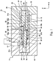
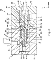
- Figs. 1 and 2 are sectional views showing a spool valve according to the embodiment.
- Fig. 1 shows the case where a spool is in a neutral position
- Fig. 2 shows the case where the spool is in a supply position.
- the spool valve (spool cartridge valve) 10 includes a valve body 20 having a cylindrical shape and a spool 30 housed in the valve body 20 so as to be movable in the axial direction.
- the axial direction refers to the direction of the central axis of the spool 30 (the longitudinal direction of the spool 30, or the direction X)
- “one axial end side” refers to the side of the spool 30 having a load pressure applied thereto (the positive side in the direction X)
- “the other axial end side” refers to the side of the spool 30 having a pilot pressure applied thereto (the negative side in the direction X).
- the valve body 20 has a spool receiving hole 21 that receives the spool 30 and extends in the axial direction.
- a pressure source port 22 is disposed in the one axial end side of the valve body 20.
- the pressure source port 22 receives the flow of a working fluid such as an oil having a load pressure.
- the pressure source port 22 is in communication with the one axial end side of the spool receiving hole 21 and is connected to a pressure source such as a pump.
- a control port 23 is formed to face the spool receiving hole 21.
- the control port 23 extends perpendicularly to the axial direction.
- the control port 23 is connected to a hydraulic apparatus (not shown) to be supplied with an oil for control.
- the control port 23 communicates with the pressure source port 22, and the oil having the load pressure flows out through the control port 23.
- the control port 23 is closed by the spool 30 and does not communicate with the pressure source port 22.
- a pilot source port 24 is disposed in the other axial end side of the valve body 20.
- the pilot source port 24 receives the flow of an oil having a pilot pressure.
- the pilot pressure is significantly smaller than the load pressure.
- the pilot source port 24 is in communication with the other axial end side of the spool receiving hole 21 and is connected to a pilot source such as an electromagnetic valve.
- a drain port 25 is formed in the side surface of the valve body 20.
- the drain port 25 is in communication with the spool receiving hole 21 and is connected to, for example, a tank T for storing the oil.
- an inner circumferential groove 21a In the inner side surface of the valve body 20, there are provided an inner circumferential groove 21a, a shoulder movement space 21b, and a drain port communication space 21c.
- the inner circumferential groove 21a, the shoulder movement space 21b, and the drain port communication space 21c are arranged in this order from the one axial end side toward the other axial end side.
- Each of the inner circumferential groove 21a, the shoulder movement space 21b, and the drain port communication space 21c constitutes a part of the spoo I receiving hole 21.
- the inner circumferential groove 21a extends annularly over the entire circumference of the inner side surface of the valve body 20 and communicates with the control port 23.
- the shoulder movement space 21b allows a shoulder 34 (described later) to move therein and communicates with the pressure sou rce port 22 via a first communication hole 35 (described later).
- the drain port communication space 21c extends annularly over the entire circumference of the inner side surface of the valve body 20 and communicates with the drain port 25.
- the drain port communication space 21c allows an other-end side step 37 of the spool 30 to move therein.
- the first step 26 is positioned on the other axial end side of the drain port communication space 21c, and when the spool 30 moves most toward the other axial end side, the first step 26 contacts with the other-end side step 37 of the spool 30.
- the second step 27 is positioned on the other axial end side of the shoulder movement space 21b and is joined to the other end side of a spring 40 (described later).
- the third step 28 is positioned on the one axial end side of the shoulder movement space 21b. When the spool 30 moves most toward the one axial end side, the third step 28 contacts with a second acting surface 34b (described later) of the spool 30.
- the valve body 20 is not necessarily constituted by a single member, but may be constituted by a plurality of members joined together.
- the spool 30 moves in the spool receiving hole 21 of the valve body 20 between the neutral position ( Fig. 1 ) and the supply position ( Fig. 2 ).
- Fig. 1 when the pilot pressure is not supplied through the pilot source port 24 of the valve body 20, the spool 30 enters the neutral position on the one axial end side, and the spool 30 closes the control port 23.
- Fig. 2 when the pilot pressure is supplied through the pilot source port 24 of the valve body 20, the spool 30 moves toward the other axial end side and enters the supply position, and the control port 23 is opened to be in communication with the pressure source port 22.
- the spool 30 has a load pressure acting surface 31 having a circular shape and formed on the one axial end side and a pilot pressure acting surface 32 having a circular shape and formed on the other axial end side. That is, the load pressure acting surface 31 and the pilot pressure acting surface 32 are opposed to each other in the axial direction.
- the load pressure acting surface 31 is in communication with the pressure source port 22 of the valve body 20 and is acted on by the oil having the load pressure from the pressure source.
- the pilot pressure acting surface 32 is in communication with the pilot source port 24 of the valve body 20 and is acted on by the oil having the pilot pressure from the pilot source.
- the spool 30 includes a spool body 33 and the shoulder 34 joined to a side surface of the spool body 33.
- the spool body 33 extends in the spool receiving hole 21 from the one axial end side toward the other axial end side.
- the spool body 33 is constituted by a solid member except for a first communication hole 35 and a second communication hole 36 (described later).
- the shoulder 34 constitutes a portion radially enlarged from the spool body 33.
- the shoulder 34 extends annularly over the entire circumference of the spool body 33 and is integrated with the spool body 33.
- the shoulder 34 has a first acting surface 34a positioned on the other axial end side and a second acting surface 34b positioned on the one axia I end side.
- the first acting surface 34a and the second acting surface 34b are opposed to each other in the axial direction.
- the spool 30 has a first communication hole 35 formed therein to communicate between the load pressure acting surface 31 and the first acting surface 34a.
- the first communication hole 35 includes an axial portion 35a extending in the axial direction and a peripheral portion 35b connected with the axial portion 35a and extending in the peripheral direction.
- the axial portion 35a is open to the load pressure acting surface 31.
- the peripheral portion 35b is open to a side surface of the spool body 33 on the other axial end side of the shoulder 34.
- the peripheral portion 35b is in communication with the other axial end side of the shoulder movement space 21b.
- the load pressure acting surface 31 and the first acting surface 34a communicate with each other, and therefore, a load pressure acting on the load pressure acting surface 31 toward the other axial end side (the negative side in the direction X) also acts on the first acting surface 34a toward the one axial end side (the positive side in the direction X).
- the spool 30 has a second communication hole 36 formed therein to communicate between the pilot pressure acting surface 32 and the second acting surface 34b.
- the second communication hole 36 includes an axial portion 36a extending in the axial direction and a peripheral portion 36b connected with the axial portion 36a and extending in the peripheral direction.
- the axial portion 36a is open to the pilot pressure acting surface 32.
- the peripheral portion 36b is open to a side surface of the spool body 33 in the second acting surface 34b and is in communication with the one axial end side of the shoulder movement space 21b.
- a part of the peripheral portion 36b is constituted by a peripheral groove formed in the second acting surface 34b.
- pilot pressure acting surface 32 and the second acting surface 34b communicate with each other, and therefore, a pilot pressure acting on the pilot pressure acting surface 32 toward the one axial end side (the positive side in the direction X) also acts on the second acting surface 34b toward the other axial end side (the negative side in the direction X).
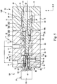
- peripheral portion 35b of the first communication hole 35 and the peripheral portion 36b of the second communication hole 36 are replaced with oblique portions extending obliquely to the axial direction. That is, as in the variation shown in Fig. 3 , the axial portion 35a of the first communication hole 35 and the axial portion 36a of the second communication hole 36 may extend in the same axis (the central axis of the spool 30), and the peripheral portions 35b, 36b may extend obliquely to the axial direction from the axial portions 35a, 36a, respectively. In this way, the axial portions 35a, 36a may be arranged in the same axis thereby to downsize the spool 30.
- the arrangement in the variation shown in Fig. 3 may also be applied to second and third embodiments described later.
- a spring (first biasing member) 40 is interposed between the valve body 20 and the spool 30 so as to press the spool 30 toward the one axial side.
- the spring 40 is a compression spring. More specifically, one end of the spring 40 is joined to the first acting surface 34a of the shoulder 34, and the other end of the spring 40 is joined to the second step 27 of the valve body 20. Thus, the spring 40 presses the spool 30 via the shoulder 34 toward the one axial end side.
- the area of the load pressure acting surface 31 of the spool 30 is equal to the area of the first acting surface 34a of the shoulder 34.
- the area of the load pressure acting surface 31 refers to the entire area of the load pressure acting surface 31 having, for example, a circular shape, including the area of the opening of the first communication hole 35.
- the area of the first acting surface 34a refers to the entire area of the first acting surface 34a having, for example, an annular shape.
- the load pressure acting surface 31 and the first acting surface 34a have the same area, and therefore, the force applied by the load pressure to the load pressure acting surface 31 (the force applied toward the other axial end side (the negative side in the direction X)) is balanced with the force applied by the load pressure to the first acting surface 34a (the force applied toward the one axial end side (the positive side in the direction X)). Therefore, in a neutral state, the spool 30 is urged toward the one axial end side only by the pressing force of the spring 40.
- the area of the pilot pressure acting surface 32 is smaller than the area of the second acting surface 34b of the shoulder 34.
- the area of the pilot pressure acting surface 32 refers to the entire area of the pilot pressure acting surface 32 having, for example, a circular shape, including the area of the opening of the second communication hole 36.
- the area of the second acting surface 34b refers to the entire area of the second acting surface 34b having, for example, an annular shape.
- the area of the pilot pressure acting surface 32 is smaller than the area of the second acting surface 34b, and therefore, when the pilot pressure is applied to the pilot pressure acting surface 32, the spool 30 can be moved from the one axial end side (the positive side in the direction X) toward the other axial end side (the negative side in the direction X) against the biasing force of the spring 40. Therefore, when the pilot pressure is applied to the pilot pressure acting surface 32, the spool 30 can be displaced from the neutral state to the supply position.
- the area of the second acting surface 34b is smaller than the area of the first acting surface 34a described above.
- the valve body 20 is housed in a block 11.
- the block 11 includes a first block portion 12 on the one axial end side and a second block portion 13 on the other axial end side.
- the block 11 has formed therein a pressure source channel 14, a control channel 15, a pilot source channel 16, and a first drain channel 17.
- the pressure source channel 14, the control channel 15, the pilot source channel 16, and the first drain channel 17 communicate with the pressure source port, the control port 23, the pilot source port 24, and the drain port 25 of the valve body 20, respectively.
- a tank pressure (a low pressure) acts on the pilot pressure acting surface 32 of the spool 30 toward the one axial end side. At this time, the tank pressure also acts on the second acting surface 34b of the shoulder 34. Further, since the drain port communication space 21 communicates with the drain port 25, the tank pressure also acts on the other-end side step 37 of the valve body 20.
- An oil having the load pressure is supplied through the pressure source port 22 of the valve body 20. Therefore, the load pressure acts on the load pressure acting surface 31 of the spool 30 toward the other axial end side.
- the oil having the load pressure also flows from the load pressure acting surface 31 into the shoulder movement space 21b through the first communication hole 35. Therefore, the load pressure acts on the first acting surface 34a of the shoulder 34 toward the one axial end side.
- the area of the load pressure acting surface 31 of the spool 30 is equal to the area of the first acting surface 34a of the shoulder 34. Therefore, the pressure acting on the load pressure acting surface 31 of the spool 30 is balanced with the pressure acting on the first acting surface 34a of the shoulder 34, and thus the spool 30 is in the neutral position (see Fig. 1 ).
- the control port 23 is closed by the spool 30 and does not communicate with the pressure source port 22. Accordingly, the oil having the load pressure from the pressure source such as a pump is not supplied to the hydraulic apparatus connected to the control port 23. Meanwhile, since the spring 40 presses the spool 30 toward the one axial end side, the second acting surface 34b of the shoulder 34 contacts with the third step 28 of the valve body 20, thereby stopping the spool 30.
- the spool 30 can be retained in the neutral position irrespective of the magnitude of the load pressure.
- the spool 30 moves toward the other axial end side to reach the supply position (see Fig. 2 ).
- the load pressure acting surface 31 of the spool 30 moves to directly above the control port 23, and thus the control port 23 is opened and in communication with the pressure source port 22.
- the oil is supplied from the pressure source such as a pump connected to the pressure source port 22 to the hydraulic apparatus connected to the control port 23.
- the amount of oil supplied from the pressure source to the hydraulic apparatus when the spool 30 is in the supply position can be varied in accordance with the overlapping area of the spool 30 and the control port 23.
- the other-end side step 37 of the spool 30 contacts with the first step 26 of the valve body 20, and the spool 30 stops moving.
- the pressure acting on the load pressure acting surface 31 of the spool 30 is constantly balanced with the pressure acting on the first acting surface 34a of the shoulder 34, and thus the magnitude of the load pressure acting on the load pressure acting surface 31 does not affect the movement of the spool 30.
- the spool 30 has the load pressure acting surface 31 and the pilot pressure acting surface 32.
- the load pressure acting surface 31 is formed on the one axial end side and acted on by the load pressure
- the pilot pressure acting surface 32 is formed on the other axial end side and acted on by the pilot pressure.
- the direction in which the oil having the load pressure is supplied to the control port 23 is aligned with the direction in which the oil having the pilot pressure is supplied to the pilot source port 24.
- This arrangement makes it possible to downsize the spool valve 10 and configure it such that the direction of action of the pilot pressure is opposite to the direction of action of the load pressure. Therefore, a fluid apparatus having the spool valve 10 neither requires a large space nor have a large size, unlike a fluid apparatus having the conventional spool valve, in which the pilot pressure is supplied from a direction perpendicular to the axial direction, for example.
- the area of the load pressure acting surface 31 is equal to the area of the first acting surface 34a of the shoulder 34. Therefore, the pressure acting on the load pressure acting surface 31 of the spool 30 can be balanced with the pressure acting on the first acting surface 34a of the shoulder 34, irrespective of the magnitude of the load pressure.
- the area of the pilot pressure acting surface 32 is smaller than the area of the second acting surface 34b of the shoulder 34. Therefore, when the pilot pressure is applied to the pilot pressure acting surface 32, the spool 30 can be moved from the neutral state to the supply position.
- the pilot pressure acting surface 32 when the pilot pressure acts on the pilot pressure acting surface 32, the pilot pressure acts on the second acting surface 34b of the shoulder 34 to move the spool 30 toward the other axial end side.
- the pilot pressure acting surface 32 when the pilot pressure acts on the pilot pressure acting surface 32, the pilot pressure acts on the second acting surface 34b of the shoulder 34 to move the spool 30 toward the other axial end side.
- the spring 40 presses the spool 30 toward the one axial end side. Therefore, when the pilot pressure does not act on the pilot pressure acting surface 32, the shoulder 34 is pressed toward the one axial end side, and the spool 30 is retained in the neutral position.
- FIGs. 4 to 6 are sectional views showing a valve system according to the embodiment.
- the second embodiment shown in Figs. 4 to 6 are distinctive in that an electromagnetic proportional valve is provided on the other axial end side of the spool.
- this embodiment is configured in substantially the same way as the first embodiment described above.
- the same elements as in the first embodiment are denoted by the same reference numerals and detailed descriptions thereof will be omitted.
- spool of the spool valve is in the neutral position and an electromagnetic proportional valve spool of the electromagnetic proportional valve is in the discharge position.
- spool of the spool valve is in the supply position and the electromagnetic proportional valve spool of the electromagnetic proportional valve is in the supply position.
- spool of the spool valve is in the supply position and the electromagnetic proportional valve spool of the electromagnetic proportional valve is in the neutral position.
- the valve system 100 includes the spool valve 10 and the electromagnetic proportional valve 50 connected to the spool valve 10.
- the spool valve 10 is substantially the same as the spool valve 10 in the first embodiment and thus is not described here.
- the electromagnetic proportional valve 50 is connected to the other axial end side of the spool valve 10 and is configured to cause the pilot pressure to act on the pilot pressure acting surface 32 of the spool valve 10.
- the electromagnetic proportional valve 50 is retained in any of a supply position, a discharge position, and a neutral position.
- the electromagnetic proportional valve 50 allow communication between a pilot pressure source as a source for supplying the oil and the pilot source channel 16 of the spool valve 10, and the oil is supplied from the pilot pressure source to the spool valve 10.
- the electromagnetic proportional valve 50 In the discharge position, allow communication between the tank T for storing the oil and the pilot source channel 16 of the spool valve 10, and the oil is discharged from the pilot source channel 16 into the tank T.
- the electromagnetic proportional valve 50 shuts off the spool valve 10 from the pilot pressure source and the tank T.
- the main components of the electromagnetic proportional valve 50 include an electromagnetic proportional valve body 60, an electromagnetic proportional valve spool 70, and a drive device 51.
- the electromagnetic proportional valve spool 70 is housed in the electromagnetic proportional valve body 60 so as to be movable in the axial direction, and the drive device 51 is disposed on the electromagnetic proportional valve body 60 and configured to press the electromagnetic proportional valve spool 70 toward the one axial end side.
- the electromagnetic proportional valve 50 switches a flow path between the supply position, the discharge position, and the neutral position by moving the electromagnetic proportional valve spool 70.
- the drive device 51 drives the electromagnetic proportional valve spool 70 to control the position of the electromagnetic proportional valve spool 70.
- the drive device 51 includes a drive rod 52 and a drive unit 53 retaining the drive rod 52.
- the drive rod 52 is retained by the drive unit 53 so as to be able to advance and retract along the central axis thereof.
- the drive unit 53 controls driving of the drive rod 52 in the axial direction (the direction X).
- the drive device 51 shown is configured as a solenoid actuator.
- the drive rod 52 moves toward the one axial end side (the positive side in the direction X) against the biasing force of a spring (a biasing member) 80 provided in the electromagnetic proportional valve body 60.
- the amount of movement of the drive rod 52 is proportional to the magnitude of the excitation current in the solenoid coil of the drive unit 53, if no reaction force is applied from the electromagnetic proportional valve spool 70.
- the drive rod 52 projects from the drive unit 53 in proportional to the magnitude of the excitation current.
- the electromagnetic proportional valve body 60 has a spool receiving hole 61.
- the electromagnetic proportional valve spool 70 which has a shaft-like shape, is movable in the axial direction in the spool receiving hole 61.
- the drive rod 52 can advance into and retract from the spool receiving hole 61.
- the spring 80 is disposed in the electromagnetic proportional valve body 60.
- the spring 80 biases the electromagnetic proportional valve spool 70 toward the drive rod 52.
- the distal end portion of the drive rod 52 contacts with the electromagnetic proportional valve spool 70.
- the spring 80 is a compression spring.
- the spring 80 retains the contact between the drive rod 52 and the electromagnetic proportional valve spool 70.
- the biasing force of the spring 80 is significantly smaller than a thrust applied from the drive rod 52 to the electromagnetic proportional valve spool 70.
- the electromagnetic proportional valve spool 70 When the drive rod 52 advances from the drive unit 53, the electromagnetic proportional valve spool 70 is pressed by the drive rod 52 and moves with respect to the electromagnetic proportional valve body 60. When the drive rod 52 retracts into the drive unit 53, the electromagnetic proportional valve spool 70 is pressed by the spring 80 and moves with respect to the electromagnetic proportional valve body 60 while contacting with the drive rod 52.
- the electromagnetic proportional valve body 60 has a pilot pressure source port 63, a drain port 64, and a control port 65 formed therein.
- the electromagnetic proportional valve spool 70 has channels 72, 73, 74 formed therein.
- the control port 65 communicates with the drain port 64, and the pilot pressure source port 63 is shut off from the other ports 64, 65.
- the control port 65 communicates with the pilot pressure source port 63, and the drain port 64 is shut off from the other ports 63, 65.
- each of the ports 63, 64, 65 is shut off from the other ports.
- the control port 65 is open to the spool receiving hole 61 and outputs the pilot pressure to the pilot source port 24 of the spool valve 10. Thus, the control port 65 supplies the oil having the pilot pressure to the spool valve 10.
- the pilot pressure source port 63 is open to the spool receiving hole 61 and communicates with the pilot pressure source such as a pump.
- the drain port 64 is open to the spool receiving hole 61 and communicates with the tank T for storing the oil.
- the oil in which the electromagnetic proportional valve spool 70 is in the supply position the oil is supplied from the pilot pressure source to the spool valve 10, and in the electromagnetic proportional valve 50 in which the electromagnetic proportional valve spool 70 is in the discharge position, the oil is discharged from the spool valve 10 to the tank T.
- the electromagnetic proportional valve 50 in which the electromagnetic proportional valve spool 70 is in the neutral position the oil in the spool valve 10 is retained.
- the electromagnetic proportional valve body 60 has a first core 66 and a second core 67 fixed thereto.
- the first core 66 has a through-hole passed by the drive rod 52 of the drive device 51 for advancement and retraction.
- the first core 67 has a through-hole penetrated by the drive rod 52 of the drive device 51 for advancement and retraction.
- the distal end portion of the drive rod 52 is positioned in the spool receiving hole 61.
- a spare chamber 68 is defined by the first core 66, the second core 67, and the electromagnetic proportional valve body 60. Between the drain po rt 64 and the spare chamber 68, there is provided a connecting channel 69. The connecting channel 69 is formed in the electromagnetic proportional valve body 60. The connecting channel 69 communicates between the spare chambe r 68 and the drain port 64.
- the electromagnetic proportional valve spool 70 is pressed on the one axial end side thereof by the spring 80 and thus is biased toward the drive rod 52.
- the electromagnetic proportional valve spool 70 contacts on the other axial end side thereof with the distal end portion of the drive rod 52.
- the electromagnetic proportional valve spool 70 has formed therein a main channel 72 extending in the axial direction.
- the main channel 72 is open to the control port 65.
- the electromagnetic proportional valve spool 70 also has formed therein a first branch channel 73 and a second branch channel 74, each connecting with the main channel 72.
- the first branch channel 73 communicates between the pilot pressure source port 63 and the main channel 72.
- the second branch channel 74 communicates between the drain port 64 and the main channel 72.
- the electromagnetic proportional valve spool 70 has formed therein a third branch channel 75 that communicates between the main channel 72 and an action space 71. Accordingly, the action space 71 is in communication with the control port 65 via the third branch channel 75 and the main channel 72. The action space 71 is retained at the pressure of the oil in the control port 65.
- the block 11 further has a pilot pressure supply channel 18 and a second drain channel 19 formed therein.
- the pilot pressure supply channel 18 and the second drain channel 19 communicate with the pilot pressure source port 63 and the drain port 64 of the electromagnetic proportional valve body 60, respectively.
- the drive rod 52 is retracted toward the drive unit 53 by the biasing force of the spring 80.
- the electromagnetic proportional valve spool 70 is contacted with the drive rod 52 by the biasing force of the spring 80 at the discharge position shown in Fig. 4 .
- the control port 65 is in communication with the drain port 64 via the main channel 72 and the second branch channel 74 of the electromagnetic proportional valve spool 70. Accordingly, the pilot source port 24 of the spool valve 10 is in communication with the tank T connected to the drain port 64.
- the drive rod 52 advances from the drive unit 53 and drives the electromagnetic proportional valve spool 70.
- the electromagnetic proportional valve spool 70 moves from the discharge position to the neutral position.
- the communication between the second branch channel 74 and the drain port 64 is shut off while the communication between the first branch channel 73 and the pilot pressure source port 63 remains shut off. Therefore, the control port 65 is shut off from both the pilot pressure source port 63 and the drain port 64. Accordingly, no oil is supplied to or discharged from the spool valve 10 connected to the control port 65.
- the drive rod 52 When a larger excitation current flows in the solenoid coil of the drive unit 53, the drive rod 52 further advances the electromagnetic proportional valve spool 70, and the first branch channel 73 of the electromagnetic proportional valve spool 70 moves to directly above the pilot pressure source port 63.
- the control port 65 In the supply position shown in Fig. 5 , the control port 65 is in communication with the pilot pressure source port 63 via the main channel 72 and the first branch channel 73 of the electromagnetic proportional valve spool 70. Accordingly, the oil having the pilot pressure is supplied from the pilot pressure source such as a pump connected to the pilot pressure source port 63 to the pilot source port 24 of the spool valve 10 connected to the control port 65.
- control port 65 is in communication with the action space 71 via the main channel 72 and the third branch channel 75 of the electromagnetic proportional valve spool 70. Accordingly, the action space 71 receives a pressure equal to the pilot pressure output to the control port 65. In the action space 71, the distal end portion of the drive rod 52 is exposed in the axial direction. Therefore, the pilot pressure constantly acts on the drive rod 52 in a direct manner in a direction opposite to the thrust applied to the electromagnetic proportional valve spool 70 by the drive rod 52.
- the oil having the pilot pressure is supplied from the electromagnetic proportional valve 50 to the spool valve 10, the pilot pressure acts on the pilot pressure acting surface 32 of the spool valve 10. Therefore, the spool 30 of the spool valve 10 is displaced from the neutral position to the supply position (see the description of the first embodiment for details of the operation of the spool 30).
- the movement of the spool 30 causes the control port 23 to be opened and in communication with the pressure source port 22. Accordingly, the oil is supplied from the pressure source such as a pump connected to the pressure source port 22 to the hydraulic apparatus connected to the control port 23.
- the drive rod 52 When the excitation of the solenoid coil of the drive unit 53 is reduced, the drive rod 52 is moved back toward the drive unit 53 to some degree. At this time, the electromagnetic proportional valve spool 70 reaches the neutral position shown in Fig. 6 .
- the electromagnetic proportional valve spool 70 When the electromagnetic proportional valve spool 70 is in the neutral position, the communication between the first branch channel 73 and the pilot pressure source port 63 is shut off while the communication between the second branch channel 74 and the drain port 64 remains shut off. Therefore, the control port 65 is shut off from both the pilot pressure source port 63 and the drain port 64. Accordingly, the control port 65 is retained at the pilot pressure, and the pilot pressure acting surface 32 of the spool valve 10 remains acted on by the pilot pressure. Accordingly, the spool 30 of the spool valve 10 is retained in the supply position, and the oil continues to be supplied from the pressure source such as a pump connected to the pressure source port 22 to the hydraulic apparatus connected to the control port 23.
- the pressure source such as
- Figs. 7 to 10 are sectional views showing a valve system according to the embodiment.
- the third embodiment shown in Figs. 7 to 10 are distinctive in that the spring 80 disposed in the electromagnetic proportional valve body 60 is replaced with a feedback spring 90 connecting between the spool 30 of the spool valve 10 and the electromagnetic proportional valve spool 70 of the electromagnetic proportional valve 50.
- this embodiment is configured in substantially the same way as the second embodiment described above.
- the same elements as in the first and second embodiments are denoted by the same reference numerals and detailed descriptions thereof will be omitted.
- the spool of the spool valve is in the neutral position and the electromagnetic proportional valve spool of the electromagnetic proportional valve is in the discharge position.
- the spool of the spool valve is in the neutral position and the electromagnetic proportional valve spool of the electromagnetic proportional valve is in the neutral position.
- the spool of the spool valve is in the supply position and the electromagnetic proportional valve spool of the electromagnetic proportional valve is in the supply position.
- the spool of the spool valve is in the supply position and the electromagnetic proportional valve spool of the electromagnetic proportional valve is in the discharge position.
- the valve system 100A includes the spool valve 10 and the electromagnetic proportional valve 50 connected to the spool valve 10.
- the spool valve 10 and the electromagnetic proportional valve 50 are substantially the same as those in the first embodiment and the second embodiment and thus are not described here.
- the spool 30 of the spool valve 10 and the electromagnetic proportional valve spool 70 of the electromagnetic proportional valve 50 are connected to each other by the feedback spring (a second biasing member) 90.
- the feedback spring 90 is a compression spring. More specifically, the feedback spring 90 elastically connects between the pilot pressure acting surface 32 of the spool 30 and the one axial end side of the electromagnetic proportional valve spool 70. With this arrangement, feedback control of the spool 30 of the spool valve 10 is possible.
- the drive rod 52 is retracted toward the drive unit 53 by the biasing force of the feedback spring 90.
- the electromagnetic proportional valve spool 70 is in the discharge position shown in Fig. 7 .
- the control port 65 is in communication with the drain port 64 via the main channel 72 and the second branch channel 74 of the electromagnetic proportional valve spool 70. Accordingly, the pilot source port 24 of the spool valve 10 is in communication with the tank T connected to the drain port 64.
- the drive rod 52 advances from the drive unit 53 and drives the electromagnetic proportional valve spool 70.
- the electromagnetic proportional valve spool 70 moves from the discharge position to the neutral position (see Fig. 8 ).
- the electromagnetic proportional valve spool 70 is in the neutral position, the communication between the second branch channel 74 and the drain port 64 is shut off while the communication between the first branch channel 73 and the pilot pressure source port 63 remains shut off. Therefore, the control port 65 is shut off from both the pilot pressure source port 63 and the drain port 64. Accordingly, no oil is supplied to or discharged from the spool valve 10 connected to the control port 65.
- the drive rod 52 When a larger excitation current flows in the solenoid coil of the drive unit 53, the drive rod 52 further advances the electromagnetic proportional valve spool 70, and the first branch channel 73 of the electromagnetic proportional valve spool 70 moves to directly above the pilot pressure source port 63. Therefore, as shown in Fig. 9 , the electromagnetic proportional valve spool 70 reaches the supply position. In the supply position, the control port 65 is in communication with the pilot pressure source port 63 via the main channel 72 and the first branch channel 73 of the electromagnetic proportional valve spool 70. Accordingly, the oil having the pilot pressure is supplied from the pilot pressure source such as a pump connected to the pilot pressure source port 63 to the pilot source port 24 of the spool valve 10 connected to the control port 65.
- the pilot pressure source such as a pump connected to the pilot pressure source port 63 to the pilot source port 24 of the spool valve 10 connected to the control port 65.
- the pilot pressure acts on the pilot pressure acting surface 32 of the spool valve 10. Therefore, the spool 30 of the spool valve 10 is moved toward the other axial end side and is displaced from the neutral position to the supply position (see Fig. 9 ).
- This movement of the spool 30 of the spool valve 10 causes the control port 23 to be opened and in communication with the pressure source port 22. Accordingly, the oil is supplied from the pressure source such as a pump connected to the pressure source port 22 to the hydraulic apparatus connected to the control port 23.
- the feedback spring 90 As the spool 30 is moved toward the other axial end side, the feedback spring 90 is more compressed. Therefore, the biasing force of the feedback spring 90 causes the electromagnetic proportional valve spool 70 to move toward the other axial end side against the pressing force of the drive rod 52.
- the electromagnetic proportional valve spool 70 moves via the neutral position to the discharge position (see Fig. 10 ).
- the control port 65 communicates with the drain port 64 and is shut off from the pilot pressure source port 63. Accordingly, the oil from the pilot source port 24 of the spool valve 10 is collected into the tank T connected to the drain port 64, and the pressure acting on the pilot pressure acting surface 32 is reduced.
- the spool 30 When the pressure acting on the pilot pressure acting surface 32 is reduced, the spool 30 returns toward the one axial end side by the biasing force of the spring 80. As the spool 30 is moved toward the one axial end side, the feedback spring 90 is more stretched. Therefore, the biasing force of the feedback spring 90 is reduced, and the electromagnetic proportional valve spool 70 is moved toward the one axial end side by the pressing force of the drive rod 52. As a result, the electromagnetic proportional valve spool 70 moves via the neutral position and reaches the supply position again (see Fig. 9 ). When the electromagnetic proportional valve spool 70 enters the supply position, the control port 65 communicates with the pilot pressure source port 63 and is shut off from the drain port 64. Accordingly, the oil having the pilot pressure is supplied again from the pilot pressure source to the spool valve 10.
- the electromagnetic proportional valve spool 70 moves repeatedly between the supply position ( Fig. 9 ) and the discharge position ( Fig. 10 ), such that the spool 30 is controlled into a position where the biasing force of the feedback spring 90 is balanced with the pressing force of the drive rod 52 applied by the drive device 51.
- the position of the spool 30 is controlled (force-feedback controlled) such that the spool 30 can be retained in position even when, for example, the pilot pressure applied by the electromagnetic proportional valve 50 is varied by a disturbance, and therefore, the spool 30 can be controlled stably.
- this force feedback control is implemented with a simple arrangement, the valve system 100A can be compact.
Landscapes
- Engineering & Computer Science (AREA)
- General Engineering & Computer Science (AREA)
- Mechanical Engineering (AREA)
- Fluid-Driven Valves (AREA)
- Multiple-Way Valves (AREA)
- Magnetically Actuated Valves (AREA)
- Sliding Valves (AREA)
Abstract
Description
- The present invention relates to a spool valve and a valve system.
- In conventional spool valves, a spool is moved according to whether or not a pilot pressure acts thereon. The conventional spool valves are configured such that a pilot pressure acts from a direction different from the direction of action of a load pressure (a direction perpendicular to the direction of action of a load pressure) so as to control movement of the spool (see, for example, Patent Literature 1).
- However, for example, a fluid apparatus having the conventional spool valve, in which a pilot pressure is supplied from a direction perpendicular to the direction of action of a load pressure, unfavorably requires a large space and has a large size. In other cases, the direction of action of the pilot pressure needs to be opposite to the direction of action of the load pressure due to requirements related to layout of a fluid apparatus.
- It is also possible that the direction of action of the pilot pressure is opposite to the direction of action of the load pressure on the spool, and the ratio between these pressures determines the area of a surface acted on by the pilot pressure and the area of a surface acted on by the load pressure. However, a pilot pressure is typically very small as compared to a load pressure. Therefore, it is impractical to attempt to balance the pilot pressure and the load pressure by adjusting the area of the surface acted on by the load pressure and the area of the surface acted on by the pilot pressure, because such a fluid apparatus has a very large structure.
- Patent Literature 1: Japanese Patent Application Publication No.
Hei 4-54111 - The present invention addresses the above drawbacks, and one object thereof is to provide a spool valve and a valve system having a small size and configured such that the direction of action of the pilot pressure can be opposite to the direction of action of the load pressure.
- The present invention is a spool valve comprising: a valve body; and a spool housed in the valve body so as to be movable in an axial direction, the spool having a load pressure acting surface and a pilot pressure acting surface, the load pressure acting surface being formed on one axial end side of the spool and configured to be acted on by a load pressure, the pilot pressure acting surface being formed on another axial end side of the spool and configured to be acted on by a pilot pressure, wherein the spool includes a spool body and a shoulder radially enlarged from the spool body, the shoulder has a first acting surface positioned on the other axial end side and a second acting surface positioned on the one axial end side, and the spool has a first communication hole and a second communication hole formed therein, the first communication hole communicating between the load pressure acting surface and the first acting surface of the shoulder, the second communication hole communicating between the pilot pressure acting surface and the second acting surface of the shoulder.
- The present invention is the spool valve, wherein an area of the load pressure acting surface is equal to an area of the first acting surface of the shoulder.
- The present invention is the spool valve, wherein an area of the pilot pressure acting surface is smaller than an area of the second acting surface of the shoulder.
- The present invention is the spool valve, wherein when the pilot pressure acts on the pilot pressure acting surface, the pilot pressure acts on the second acting surface of the shoulder to move the spool toward the other axial end side.
- The present invention is the spool valve, further comprising a first biasing member for pressing the spool toward the one axial end side.
- The present invention is a valve system comprising: the spool valve; and an electromagnetic proportional valve connected to the other axial end side of the spool valve and configured to cause the pilot pressure to act on the pilot pressure acting surface of the spool valve.
- The present invention is the valve system, wherein the electromagnetic proportional valve includes an electromagnetic proportional valve body, an electromagnetic proportional valve spool, and a drive device, the electromagnetic proportional valve spool being housed in the electromagnetic proportional valve body so as to be movable in the axial direction, and the drive device being disposed on the electromagnetic proportional valve body and configured to press the electromagnetic proportional valve spool toward the one axial end side, and the spool of the spool valve and the electromagnetic proportional valve spool of the electromagnetic proportional valve are connected together by a second biasing member.
- The present invention provides a spool valve and a valve system having a small size and configured such that the direction of action of the pilot pressure can be opposite to the direction of action of the load pressure.
-
-
Fig. 1 is a sectional view showing a spool valve according to a first embodiment of the present invention, in which a spool of the spool valve is in a neutral position. -
Fig. 2 is a sectional view showing the spool valve according to the first embodiment of the present invention, in which the spool of the spool valve is in a supply position. -
Fig. 3 is a sectional view showing a spool valve according to a variation of the first embodiment of the present invention, in which the spool of the spool valve is in a neutral position. -
Fig. 4 is a sectional view showing a valve system according to a second embodiment of the present invention, in which an electromagnetic proportional valve spool of an electromagnetic proportional valve is in a discharge position. -
Fig. 5 is a sectional view showing the valve system according to the second embodiment of the present invention, in which the electromagnetic proportional valve spool of the electromagnetic proportional valve is in a supply position. -
Fig. 6 is a sectional view showing the valve system according to the second embodiment of the present invention, in which the electromagnetic proportional valve spool of the electromagnetic proportional valve is in a neutral position. -
Fig. 7 is a sectional view showing a valve system according to a third embodiment of the present invention, in which a spool of a spool valve is in a neutral position and an electromagnetic proportional valve spool of an electromagnetic proportional valve is in a discharge position. -
Fig. 8 is a sectional view showing the valve system according to the third embodiment of the present invention, in which the spool of the spool valve is in the neutral position and the electromagnetic proportional valve spool of the electromagnetic proportional valve is in a neutral position. -
Fig. 9 is a sectional view showing the valve system according to the third embodiment of the present invention, in which the spool of the spool valve is in a supply position and the electromagnetic proportional valve spool of the electromagnetic proportional valve is in a supply position. -
Fig. 10 is a sectional view showing the valve system according to the third embodiment of the present invention, in which the spool of the spool valve is in the supply position and the electromagnetic proportional valve spool of the electromagnetic proportional valve is in the discharge position. - The first embodiment of the present invention will now be described with reference to
Figs. 1 and2 .Figs. 1 and2 are sectional views showing a spool valve according to the embodiment.Fig. 1 shows the case where a spool is in a neutral position, andFig. 2 shows the case where the spool is in a supply position. - As shown in
Figs. 1 and2 , the spool valve (spool cartridge valve) 10 according to the embodiment includes avalve body 20 having a cylindrical shape and aspool 30 housed in thevalve body 20 so as to be movable in the axial direction. - In this specification, "the axial direction" refers to the direction of the central axis of the spool 30 (the longitudinal direction of the
spool 30, or the direction X), "one axial end side" refers to the side of thespool 30 having a load pressure applied thereto (the positive side in the direction X), and "the other axial end side" refers to the side of thespool 30 having a pilot pressure applied thereto (the negative side in the direction X). - The
valve body 20 has aspool receiving hole 21 that receives thespool 30 and extends in the axial direction. Apressure source port 22 is disposed in the one axial end side of thevalve body 20. Thepressure source port 22 receives the flow of a working fluid such as an oil having a load pressure. Thepressure source port 22 is in communication with the one axial end side of thespool receiving hole 21 and is connected to a pressure source such as a pump. - In a side surface of the
valve body 20, acontrol port 23 is formed to face thespool receiving hole 21. Thecontrol port 23 extends perpendicularly to the axial direction. Thecontrol port 23 is connected to a hydraulic apparatus (not shown) to be supplied with an oil for control. When thespool 30 is in a supply position (seeFig. 2 ), thecontrol port 23 communicates with thepressure source port 22, and the oil having the load pressure flows out through thecontrol port 23. When thespool 30 is in a neutral position (seeFig. 1 ), thecontrol port 23 is closed by thespool 30 and does not communicate with thepressure source port 22. - A
pilot source port 24 is disposed in the other axial end side of thevalve body 20. Thepilot source port 24 receives the flow of an oil having a pilot pressure. The pilot pressure is significantly smaller than the load pressure. Thepilot source port 24 is in communication with the other axial end side of thespool receiving hole 21 and is connected to a pilot source such as an electromagnetic valve. - Further, a
drain port 25 is formed in the side surface of thevalve body 20. Thedrain port 25 is in communication with thespool receiving hole 21 and is connected to, for example, a tank T for storing the oil. - In the inner side surface of the
valve body 20, there are provided an innercircumferential groove 21a, ashoulder movement space 21b, and a drainport communication space 21c. The innercircumferential groove 21a, theshoulder movement space 21b, and the drainport communication space 21c are arranged in this order from the one axial end side toward the other axial end side. Each of the innercircumferential groove 21a, theshoulder movement space 21b, and the drainport communication space 21c constitutes a part of the spoo I receivinghole 21. - The inner
circumferential groove 21a extends annularly over the entire circumference of the inner side surface of thevalve body 20 and communicates with thecontrol port 23. Theshoulder movement space 21b allows a shoulder 34 (described later) to move therein and communicates with the pressuresou rce port 22 via a first communication hole 35 (described later). The drainport communication space 21c extends annularly over the entire circumference of the inner side surface of thevalve body 20 and communicates with thedrain port 25. The drainport communication space 21c allows an other-end side step 37 of thespool 30 to move therein. - Further provided in the inner side surface of the
valve body 20 are afirst step 26, asecond step 27, and athird step 28. Thefirst step 26 is positioned on the other axial end side of the drainport communication space 21c, and when thespool 30 moves most toward the other axial end side, thefirst step 26 contacts with the other-end side step 37 of thespool 30. Thesecond step 27 is positioned on the other axial end side of theshoulder movement space 21b and is joined to the other end side of a spring 40 (described later). Thethird step 28 is positioned on the one axial end side of theshoulder movement space 21b. When thespool 30 moves most toward the one axial end side, thethird step 28 contacts with asecond acting surface 34b (described later) of thespool 30. - The
valve body 20 is not necessarily constituted by a single member, but may be constituted by a plurality of members joined together. - The
spool 30 moves in thespool receiving hole 21 of thevalve body 20 between the neutral position (Fig. 1 ) and the supply position (Fig. 2 ). As shown inFig. 1 , when the pilot pressure is not supplied through thepilot source port 24 of thevalve body 20, thespool 30 enters the neutral position on the one axial end side, and thespool 30 closes thecontrol port 23. On the other hand, as shown inFig. 2 , when the pilot pressure is supplied through thepilot source port 24 of thevalve body 20, thespool 30 moves toward the other axial end side and enters the supply position, and thecontrol port 23 is opened to be in communication with thepressure source port 22. - The
spool 30 has a loadpressure acting surface 31 having a circular shape and formed on the one axial end side and a pilotpressure acting surface 32 having a circular shape and formed on the other axial end side. That is, the loadpressure acting surface 31 and the pilotpressure acting surface 32 are opposed to each other in the axial direction. The loadpressure acting surface 31 is in communication with thepressure source port 22 of thevalve body 20 and is acted on by the oil having the load pressure from the pressure source. The pilotpressure acting surface 32 is in communication with thepilot source port 24 of thevalve body 20 and is acted on by the oil having the pilot pressure from the pilot source. - The
spool 30 includes aspool body 33 and theshoulder 34 joined to a side surface of thespool body 33. Thespool body 33 extends in thespool receiving hole 21 from the one axial end side toward the other axial end side. Thespool body 33 is constituted by a solid member except for afirst communication hole 35 and a second communication hole 36 (described later). - The
shoulder 34 constitutes a portion radially enlarged from thespool body 33. Theshoulder 34 extends annularly over the entire circumference of thespool body 33 and is integrated with thespool body 33. - The
shoulder 34 has afirst acting surface 34a positioned on the other axial end side and asecond acting surface 34b positioned on the one axia I end side. Thefirst acting surface 34a and thesecond acting surface 34b are opposed to each other in the axial direction. - The
spool 30 has afirst communication hole 35 formed therein to communicate between the loadpressure acting surface 31 and thefirst acting surface 34a. Thefirst communication hole 35 includes anaxial portion 35a extending in the axial direction and aperipheral portion 35b connected with theaxial portion 35a and extending in the peripheral direction. Theaxial portion 35a is open to the loadpressure acting surface 31. Theperipheral portion 35b is open to a side surface of thespool body 33 on the other axial end side of theshoulder 34. Theperipheral portion 35b is in communication with the other axial end side of theshoulder movement space 21b. In this way, the loadpressure acting surface 31 and thefirst acting surface 34a communicate with each other, and therefore, a load pressure acting on the loadpressure acting surface 31 toward the other axial end side (the negative side in the direction X) also acts on thefirst acting surface 34a toward the one axial end side (the positive side in the direction X). - Further, the
spool 30 has asecond communication hole 36 formed therein to communicate between the pilotpressure acting surface 32 and thesecond acting surface 34b. Thesecond communication hole 36 includes anaxial portion 36a extending in the axial direction and aperipheral portion 36b connected with theaxial portion 36a and extending in the peripheral direction. Theaxial portion 36a is open to the pilotpressure acting surface 32. Theperipheral portion 36b is open to a side surface of thespool body 33 in thesecond acting surface 34b and is in communication with the one axial end side of theshoulder movement space 21b. A part of theperipheral portion 36b is constituted by a peripheral groove formed in thesecond acting surface 34b. In this way, the pilotpressure acting surface 32 and thesecond acting surface 34b communicate with each other, and therefore, a pilot pressure acting on the pilotpressure acting surface 32 toward the one axial end side (the positive side in the direction X) also acts on thesecond acting surface 34b toward the other axial end side (the negative side in the direction X). - It is also possible that the
peripheral portion 35b of thefirst communication hole 35 and theperipheral portion 36b of thesecond communication hole 36 are replaced with oblique portions extending obliquely to the axial direction. That is, as in the variation shown inFig. 3 , theaxial portion 35a of thefirst communication hole 35 and theaxial portion 36a of thesecond communication hole 36 may extend in the same axis (the central axis of the spool 30), and theperipheral portions axial portions axial portions spool 30. The arrangement in the variation shown inFig. 3 may also be applied to second and third embodiments described later. - Referring again to
Figs. 1 and2 , a spring (first biasing member) 40 is interposed between thevalve body 20 and thespool 30 so as to press thespool 30 toward the one axial side. Thespring 40 is a compression spring. More specifically, one end of thespring 40 is joined to thefirst acting surface 34a of theshoulder 34, and the other end of thespring 40 is joined to thesecond step 27 of thevalve body 20. Thus, thespring 40 presses thespool 30 via theshoulder 34 toward the one axial end side. - In the embodiment, the area of the load
pressure acting surface 31 of thespool 30 is equal to the area of thefirst acting surface 34a of theshoulder 34. The area of the loadpressure acting surface 31 refers to the entire area of the loadpressure acting surface 31 having, for example, a circular shape, including the area of the opening of thefirst communication hole 35. The area of thefirst acting surface 34a refers to the entire area of thefirst acting surface 34a having, for example, an annular shape. In this way, the loadpressure acting surface 31 and thefirst acting surface 34a have the same area, and therefore, the force applied by the load pressure to the load pressure acting surface 31 (the force applied toward the other axial end side (the negative side in the direction X)) is balanced with the force applied by the load pressure to thefirst acting surface 34a (the force applied toward the one axial end side (the positive side in the direction X)). Therefore, in a neutral state, thespool 30 is urged toward the one axial end side only by the pressing force of thespring 40. - Depending on the spring constant of the
spring 40 and the strength of the load pressure, there may be a slight difference between the areas of the loadpressure acting surface 31 and thefirst acting surface 34a. - The area of the pilot
pressure acting surface 32 is smaller than the area of thesecond acting surface 34b of theshoulder 34. The area of the pilotpressure acting surface 32 refers to the entire area of the pilotpressure acting surface 32 having, for example, a circular shape, including the area of the opening of thesecond communication hole 36. The area of thesecond acting surface 34b refers to the entire area of thesecond acting surface 34b having, for example, an annular shape. In this way, the area of the pilotpressure acting surface 32 is smaller than the area of thesecond acting surface 34b, and therefore, when the pilot pressure is applied to the pilotpressure acting surface 32, thespool 30 can be moved from the one axial end side (the positive side in the direction X) toward the other axial end side (the negative side in the direction X) against the biasing force of thespring 40. Therefore, when the pilot pressure is applied to the pilotpressure acting surface 32, thespool 30 can be displaced from the neutral state to the supply position. The area of thesecond acting surface 34b is smaller than the area of thefirst acting surface 34a described above. - The
valve body 20 is housed in ablock 11. Theblock 11 includes afirst block portion 12 on the one axial end side and asecond block portion 13 on the other axial end side. Theblock 11 has formed therein apressure source channel 14, acontrol channel 15, apilot source channel 16, and afirst drain channel 17. Thepressure source channel 14, thecontrol channel 15, thepilot source channel 16, and thefirst drain channel 17 communicate with the pressure source port, thecontrol port 23, thepilot source port 24, and thedrain port 25 of thevalve body 20, respectively. - Operation in the embodiment configured as above will be hereinafter described.
- First, when an oil having the pilot pressure is not supplied through the
pilot source port 24 of thevalve body 20, a tank pressure (a low pressure) acts on the pilotpressure acting surface 32 of thespool 30 toward the one axial end side. At this time, the tank pressure also acts on thesecond acting surface 34b of theshoulder 34. Further, since the drainport communication space 21 communicates with thedrain port 25, the tank pressure also acts on the other-end side step 37 of thevalve body 20. - An oil having the load pressure is supplied through the
pressure source port 22 of thevalve body 20. Therefore, the load pressure acts on the loadpressure acting surface 31 of thespool 30 toward the other axial end side. The oil having the load pressure also flows from the loadpressure acting surface 31 into theshoulder movement space 21b through thefirst communication hole 35. Therefore, the load pressure acts on thefirst acting surface 34a of theshoulder 34 toward the one axial end side. - As described above, the area of the load
pressure acting surface 31 of thespool 30 is equal to the area of thefirst acting surface 34a of theshoulder 34. Therefore, the pressure acting on the loadpressure acting surface 31 of thespool 30 is balanced with the pressure acting on thefirst acting surface 34a of theshoulder 34, and thus thespool 30 is in the neutral position (seeFig. 1 ). At this time, thecontrol port 23 is closed by thespool 30 and does not communicate with thepressure source port 22. Accordingly, the oil having the load pressure from the pressure source such as a pump is not supplied to the hydraulic apparatus connected to thecontrol port 23. Meanwhile, since thespring 40 presses thespool 30 toward the one axial end side, thesecond acting surface 34b of theshoulder 34 contacts with thethird step 28 of thevalve body 20, thereby stopping thespool 30. - In this way, since the area of the load
pressure acting surface 31 of thespool 30 is equal to the area of thefirst acting surface 34a of theshoulder 34, thespool 30 can be retained in the neutral position irrespective of the magnitude of the load pressure. - In this state, when an oil having the pilot pressure is supplied through the
pilot source port 24 of thevalve body 20, the pilot pressure acts on the pilotpressure acting surface 32 of thespool 30 toward the one axial end side. At this time, the oil having the pilot pressure also flows from the pilotpressure acting surface 32 into theshoulder movement space 21b through thesecond communication hole 36. Therefore, the pilot pressure also acts on thesecond acting surface 34b of theshoulder 34. As described above, the area of the pilotpressure acting surface 32 is smaller than the area of thesecond acting surface 34b of theshoulder 34. Therefore, the pilot pressure acting on thesecond acting surface 34b of theshoulder 34 causes thespool 30 to move from the one axial end side toward the other axial end side against the biasing force of thespring 40. - The
spool 30 moves toward the other axial end side to reach the supply position (seeFig. 2 ). At this time, the loadpressure acting surface 31 of thespool 30 moves to directly above thecontrol port 23, and thus thecontrol port 23 is opened and in communication with thepressure source port 22. According ly, the oil is supplied from the pressure source such as a pump connected to thepressure source port 22 to the hydraulic apparatus connected to thecontrol port 23. The amount of oil supplied from the pressure source to the hydraulic apparatus when thespool 30 is in the supply position can be varied in accordance with the overlapping area of thespool 30 and thecontrol port 23. Subsequently, the other-end side step 37 of thespool 30 contacts with thefirst step 26 of thevalve body 20, and thespool 30 stops moving. - During this operation, the pressure acting on the load
pressure acting surface 31 of thespool 30 is constantly balanced with the pressure acting on thefirst acting surface 34a of theshoulder 34, and thus the magnitude of the load pressure acting on the loadpressure acting surface 31 does not affect the movement of thespool 30. - Subsequently, the supply of the pilot pressure from the
pilot source port 24 is stopped to cause the tank pressure to act on the pilotpressure acting surface 32. Because of the biasing force of thespring 40, thespool 30 moves from the supply position to the neutral position to close thecontrol port 23. Thus, no oil is supplied to or discharged from the hydraulic apparatus connected to thecontrol port 23. - As described above, in the embodiment, the
spool 30 has the loadpressure acting surface 31 and the pilotpressure acting surface 32. The loadpressure acting surface 31 is formed on the one axial end side and acted on by the load pressure, and the pilotpressure acting surface 32 is formed on the other axial end side and acted on by the pilot pressure. Further, the direction in which the oil having the load pressure is supplied to thecontrol port 23 is aligned with the direction in which the oil having the pilot pressure is supplied to thepilot source port 24. This arrangement makes it possible to downsize thespool valve 10 and configure it such that the direction of action of the pilot pressure is opposite to the direction of action of the load pressure. Therefore, a fluid apparatus having thespool valve 10 neither requires a large space nor have a large size, unlike a fluid apparatus having the conventional spool valve, in which the pilot pressure is supplied from a direction perpendicular to the axial direction, for example. - In the embodiment, the area of the load
pressure acting surface 31 is equal to the area of thefirst acting surface 34a of theshoulder 34. Therefore, the pressure acting on the loadpressure acting surface 31 of thespool 30 can be balanced with the pressure acting on thefirst acting surface 34a of theshoulder 34, irrespective of the magnitude of the load pressure. - In the embodiment, the area of the pilot
pressure acting surface 32 is smaller than the area of thesecond acting surface 34b of theshoulder 34. Therefore, when the pilot pressure is applied to the pilotpressure acting surface 32, thespool 30 can be moved from the neutral state to the supply position. - In the embodiment, when the pilot pressure acts on the pilot
pressure acting surface 32, the pilot pressure acts on thesecond acting surface 34b of theshoulder 34 to move thespool 30 toward the other axial end side. Thus, it is possible to control the movement of thespool 30 according to whether or not the pilot pressure acts thereon. - In the embodiment, the
spring 40 presses thespool 30 toward the one axial end side. Therefore, when the pilot pressure does not act on the pilotpressure acting surface 32, theshoulder 34 is pressed toward the one axial end side, and thespool 30 is retained in the neutral position. - Next, the second embodiment of the invention will be described.
Figs. 4 to 6 are sectional views showing a valve system according to the embodiment. The second embodiment shown inFigs. 4 to 6 are distinctive in that an electromagnetic proportional valve is provided on the other axial end side of the spool. In other respects, this embodiment is configured in substantially the same way as the first embodiment described above. InFigs. 4 to 6 , the same elements as in the first embodiment are denoted by the same reference numerals and detailed descriptions thereof will be omitted. - In
Fig. 4 , the spool of the spool valve is in the neutral position and an electromagnetic proportional valve spool of the electromagnetic proportional valve is in the discharge position. InFig. 5 , the spool of the spool valve is in the supply position and the electromagnetic proportional valve spool of the electromagnetic proportional valve is in the supply position. InFig. 6 , the spool of the spool valve is in the supply position and the electromagnetic proportional valve spool of the electromagnetic proportional valve is in the neutral position. - As shown in
Figs. 4 to 6 , thevalve system 100 according to the embodiment includes thespool valve 10 and the electromagneticproportional valve 50 connected to thespool valve 10. - The
spool valve 10 is substantially the same as thespool valve 10 in the first embodiment and thus is not described here. - The electromagnetic
proportional valve 50 is connected to the other axial end side of thespool valve 10 and is configured to cause the pilot pressure to act on the pilotpressure acting surface 32 of thespool valve 10. The electromagneticproportional valve 50 is retained in any of a supply position, a discharge position, and a neutral position. In the supply position, the electromagneticproportional valve 50 allow communication between a pilot pressure source as a source for supplying the oil and thepilot source channel 16 of thespool valve 10, and the oil is supplied from the pilot pressure source to thespool valve 10. In the discharge position, the electromagneticproportional valve 50 allow communication between the tank T for storing the oil and thepilot source channel 16 of thespool valve 10, and the oil is discharged from thepilot source channel 16 into the tank T. In the neutral position, the electromagneticproportional valve 50 shuts off thespool valve 10 from the pilot pressure source and the tank T. - As shown in
Figs. 4 to 6 , the main components of the electromagneticproportional valve 50 include an electromagneticproportional valve body 60, an electromagneticproportional valve spool 70, and adrive device 51. The electromagneticproportional valve spool 70 is housed in the electromagneticproportional valve body 60 so as to be movable in the axial direction, and thedrive device 51 is disposed on the electromagneticproportional valve body 60 and configured to press the electromagneticproportional valve spool 70 toward the one axial end side. The electromagneticproportional valve 50 switches a flow path between the supply position, the discharge position, and the neutral position by moving the electromagneticproportional valve spool 70. - The
drive device 51 drives the electromagneticproportional valve spool 70 to control the position of the electromagneticproportional valve spool 70. Thedrive device 51 includes adrive rod 52 and adrive unit 53 retaining thedrive rod 52. Thedrive rod 52 is retained by thedrive unit 53 so as to be able to advance and retract along the central axis thereof. Thedrive unit 53 controls driving of thedrive rod 52 in the axial direction (the direction X). Thedrive device 51 shown is configured as a solenoid actuator. - In the
drive device 51 configured as described above, when an excitation current flows in a solenoid coil (not shown) of thedrive unit 53, thedrive rod 52 moves toward the one axial end side (the positive side in the direction X) against the biasing force of a spring (a biasing member) 80 provided in the electromagneticproportional valve body 60. The amount of movement of thedrive rod 52 is proportional to the magnitude of the excitation current in the solenoid coil of thedrive unit 53, if no reaction force is applied from the electromagneticproportional valve spool 70. In the example shown, thedrive rod 52 projects from thedrive unit 53 in proportional to the magnitude of the excitation current. - Next, the electromagnetic
proportional valve body 60 will be described. The electromagneticproportional valve body 60 has aspool receiving hole 61. The electromagneticproportional valve spool 70, which has a shaft-like shape, is movable in the axial direction in thespool receiving hole 61. Thedrive rod 52 can advance into and retract from thespool receiving hole 61. Further, thespring 80 is disposed in the electromagneticproportional valve body 60. Thespring 80 biases the electromagneticproportional valve spool 70 toward thedrive rod 52. As a result, the distal end portion of thedrive rod 52 contacts with the electromagneticproportional valve spool 70. In the example shown, thespring 80 is a compression spring. Thespring 80 retains the contact between thedrive rod 52 and the electromagneticproportional valve spool 70. The biasing force of thespring 80 is significantly smaller than a thrust applied from thedrive rod 52 to the electromagneticproportional valve spool 70. - When the
drive rod 52 advances from thedrive unit 53, the electromagneticproportional valve spool 70 is pressed by thedrive rod 52 and moves with respect to the electromagneticproportional valve body 60. When thedrive rod 52 retracts into thedrive unit 53, the electromagneticproportional valve spool 70 is pressed by thespring 80 and moves with respect to the electromagneticproportional valve body 60 while contacting with thedrive rod 52. - The electromagnetic
proportional valve body 60 has a pilotpressure source port 63, adrain port 64, and acontrol port 65 formed therein. The electromagneticproportional valve spool 70 haschannels proportional valve spool 70 is in the discharge position shown inFig. 4 , thecontrol port 65 communicates with thedrain port 64, and the pilotpressure source port 63 is shut off from theother ports proportional valve spool 70 is in the supply position shown inFig. 5 , thecontrol port 65 communicates with the pilotpressure source port 63, and thedrain port 64 is shut off from theother ports proportional valve spool 70 is in the neutral position shown inFig. 6 , each of theports - The
control port 65 is open to thespool receiving hole 61 and outputs the pilot pressure to thepilot source port 24 of thespool valve 10. Thus, thecontrol port 65 supplies the oil having the pilot pressure to thespool valve 10. The pilotpressure source port 63 is open to thespool receiving hole 61 and communicates with the pilot pressure source such as a pump. Thedrain port 64 is open to thespool receiving hole 61 and communicates with the tank T for storing the oil. Accordingly, in the electromagneticproportional valve 50 in which the electromagneticproportional valve spool 70 is in the supply position, the oil is supplied from the pilot pressure source to thespool valve 10, and in the electromagneticproportional valve 50 in which the electromagneticproportional valve spool 70 is in the discharge position, the oil is discharged from thespool valve 10 to the tank T. In the electromagneticproportional valve 50 in which the electromagneticproportional valve spool 70 is in the neutral position, the oil in thespool valve 10 is retained. - In the example shown, the electromagnetic
proportional valve body 60 has afirst core 66 and asecond core 67 fixed thereto. Thefirst core 66 has a through-hole passed by thedrive rod 52 of thedrive device 51 for advancement and retraction. Thefirst core 67 has a through-hole penetrated by thedrive rod 52 of thedrive device 51 for advancement and retraction. The distal end portion of thedrive rod 52 is positioned in thespool receiving hole 61. - A
spare chamber 68 is defined by thefirst core 66, thesecond core 67, and the electromagneticproportional valve body 60. Between the drain po rt 64 and thespare chamber 68, there is provided a connectingchannel 69. The connectingchannel 69 is formed in the electromagneticproportional valve body 60. The connectingchannel 69 communicates between thespare chambe r 68 and thedrain port 64. - Next, the electromagnetic
proportional valve spool 70 will be described. The electromagneticproportional valve spool 70 is pressed on the one axial end side thereof by thespring 80 and thus is biased toward thedrive rod 52. The electromagneticproportional valve spool 70 contacts on the other axial end side thereof with the distal end portion of thedrive rod 52. - The electromagnetic
proportional valve spool 70 has formed therein amain channel 72 extending in the axial direction. Themain channel 72 is open to thecontrol port 65. The electromagneticproportional valve spool 70 also has formed therein afirst branch channel 73 and asecond branch channel 74, each connecting with themain channel 72. When the electromagneticproportional valve spool 70 is in the supply position, thefirst branch channel 73 communicates between the pilotpressure source port 63 and themain channel 72. When the electromagneticproportional valve spool 70 is in the discharge position, thesecond branch channel 74 communicates between thedrain port 64 and themain channel 72. - Further, the electromagnetic
proportional valve spool 70 has formed therein athird branch channel 75 that communicates between themain channel 72 and anaction space 71. Accordingly, theaction space 71 is in communication with thecontrol port 65 via thethird branch channel 75 and themain channel 72. Theaction space 71 is retained at the pressure of the oil in thecontrol port 65. - In the embodiment, the
block 11 further has a pilotpressure supply channel 18 and asecond drain channel 19 formed therein. The pilotpressure supply channel 18 and thesecond drain channel 19 communicate with the pilotpressure source port 63 and thedrain port 64 of the electromagneticproportional valve body 60, respectively. - Next, operation in the embodiment configured as above will be hereinafter described.
- First, when the solenoid coil of the
drive unit 53 of the electromagneticproportional valve 50 is not excited, thedrive rod 52 is retracted toward thedrive unit 53 by the biasing force of thespring 80. The electromagneticproportional valve spool 70 is contacted with thedrive rod 52 by the biasing force of thespring 80 at the discharge position shown inFig. 4 . At this time, thecontrol port 65 is in communication with thedrain port 64 via themain channel 72 and thesecond branch channel 74 of the electromagneticproportional valve spool 70. Accordingly, thepilot source port 24 of thespool valve 10 is in communication with the tank T connected to thedrain port 64. - In this state, the pilot pressure does not act on the pilot
pressure acting surface 32 of thespool valve 10. Therefore, thespool 30 of thespool valve 10 is retained in the neutral position (see the description of the first embodiment for details of the operation of the spool 30). At this time, thecontrol port 23 is closed by thespool 30, and therefore, the oil having the load pressure from the pressure source such as a pump is not supplied to the hydraulic apparatus connected to thecontrol port 23. - In this state, when the solenoid coil of the
drive unit 53 is excited, thedrive rod 52 advances from thedrive unit 53 and drives the electromagneticproportional valve spool 70. The electromagneticproportional valve spool 70 moves from the discharge position to the neutral position. When the electromagneticproportional valve spool 70 is in the neutral position, the communication between thesecond branch channel 74 and thedrain port 64 is shut off while the communication between thefirst branch channel 73 and the pilotpressure source port 63 remains shut off. Therefore, thecontrol port 65 is shut off from both the pilotpressure source port 63 and thedrain port 64. Accordingly, no oil is supplied to or discharged from thespool valve 10 connected to thecontrol port 65. - When a larger excitation current flows in the solenoid coil of the
drive unit 53, thedrive rod 52 further advances the electromagneticproportional valve spool 70, and thefirst branch channel 73 of the electromagneticproportional valve spool 70 moves to directly above the pilotpressure source port 63. In the supply position shown inFig. 5 , thecontrol port 65 is in communication with the pilotpressure source port 63 via themain channel 72 and thefirst branch channel 73 of the electromagneticproportional valve spool 70. Accordingly, the oil having the pilot pressure is supplied from the pilot pressure source such as a pump connected to the pilotpressure source port 63 to thepilot source port 24 of thespool valve 10 connected to thecontrol port 65. - Meanwhile, the
control port 65 is in communication with theaction space 71 via themain channel 72 and thethird branch channel 75 of the electromagneticproportional valve spool 70. Accordingly, theaction space 71 receives a pressure equal to the pilot pressure output to thecontrol port 65. In theaction space 71, the distal end portion of thedrive rod 52 is exposed in the axial direction. Therefore, the pilot pressure constantly acts on thedrive rod 52 in a direct manner in a direction opposite to the thrust applied to the electromagneticproportional valve spool 70 by thedrive rod 52. - As described above, since the oil having the pilot pressure is supplied from the electromagnetic
proportional valve 50 to thespool valve 10, the pilot pressure acts on the pilotpressure acting surface 32 of thespool valve 10. Therefore, thespool 30 of thespool valve 10 is displaced from the neutral position to the supply position (see the description of the first embodiment for details of the operation of the spool 30). The movement of thespool 30 causes thecontrol port 23 to be opened and in communication with thepressure source port 22. Accordingly, the oil is supplied from the pressure source such as a pump connected to thepressure source port 22 to the hydraulic apparatus connected to thecontrol port 23. - When the excitation of the solenoid coil of the
drive unit 53 is reduced, thedrive rod 52 is moved back toward thedrive unit 53 to some degree. At this time, the electromagneticproportional valve spool 70 reaches the neutral position shown inFig. 6 . When the electromagneticproportional valve spool 70 is in the neutral position, the communication between thefirst branch channel 73 and the pilotpressure source port 63 is shut off while the communication between thesecond branch channel 74 and thedrain port 64 remains shut off. Therefore, thecontrol port 65 is shut off from both the pilotpressure source port 63 and thedrain port 64. Accordingly, thecontrol port 65 is retained at the pilot pressure, and the pilotpressure acting surface 32 of thespool valve 10 remains acted on by the pilot pressure. Accordingly, thespool 30 of thespool valve 10 is retained in the supply position, and the oil continues to be supplied from the pressure source such as a pump connected to thepressure source port 22 to the hydraulic apparatus connected to thecontrol port 23. - In the embodiment, it is possible with a simple arrangement to drive the electromagnetic
proportional valve spool 70 with a control pressure and thereby control thespool valve 10. In other words, the arrangement to drive the electromagneticproportional valve spool 70 with the pilot pressure can be simplified significantly. Thus, the electromagneticproportional valve spool 70 can be simplified significantly. - Next, the third embodiment of the invention will be described.
Figs. 7 to 10 are sectional views showing a valve system according to the embodiment. The third embodiment shown inFigs. 7 to 10 are distinctive in that thespring 80 disposed in the electromagneticproportional valve body 60 is replaced with afeedback spring 90 connecting between thespool 30 of thespool valve 10 and the electromagneticproportional valve spool 70 of the electromagneticproportional valve 50. In other respects, this embodiment is configured in substantially the same way as the second embodiment described above. InFigs. 7 to 10 , the same elements as in the first and second embodiments are denoted by the same reference numerals and detailed descriptions thereof will be omitted. - In
Fig. 7 , the spool of the spool valve is in the neutral position and the electromagnetic proportional valve spool of the electromagnetic proportional valve is in the discharge position. InFig. 8 , the spool of the spool valve is in the neutral position and the electromagnetic proportional valve spool of the electromagnetic proportional valve is in the neutral position. InFig. 9 , the spool of the spool valve is in the supply position and the electromagnetic proportional valve spool of the electromagnetic proportional valve is in the supply position. InFig. 10 , the spool of the spool valve is in the supply position and the electromagnetic proportional valve spool of the electromagnetic proportional valve is in the discharge position. - As shown in
Figs. 7 to 10 , thevalve system 100A according to the embodiment includes thespool valve 10 and the electromagneticproportional valve 50 connected to thespool valve 10. Thespool valve 10 and the electromagneticproportional valve 50 are substantially the same as those in the first embodiment and the second embodiment and thus are not described here. - In the embodiment, the
spool 30 of thespool valve 10 and the electromagneticproportional valve spool 70 of the electromagneticproportional valve 50 are connected to each other by the feedback spring (a second biasing member) 90. Thefeedback spring 90 is a compression spring. More specifically, thefeedback spring 90 elastically connects between the pilotpressure acting surface 32 of thespool 30 and the one axial end side of the electromagneticproportional valve spool 70. With this arrangement, feedback control of thespool 30 of thespool valve 10 is possible. - Next, operation in the embodiment configured as above will be hereinafter described.
- First, when the solenoid coil of the
drive unit 53 of the electromagneticproportional valve 50 is not excited, thedrive rod 52 is retracted toward thedrive unit 53 by the biasing force of thefeedback spring 90. At this time, the electromagneticproportional valve spool 70 is in the discharge position shown inFig. 7 . Thecontrol port 65 is in communication with thedrain port 64 via themain channel 72 and thesecond branch channel 74 of the electromagneticproportional valve spool 70. Accordingly, thepilot source port 24 of thespool valve 10 is in communication with the tank T connected to thedrain port 64. - In this state, the pilot pressure does not act on the pilot
pressure acting surface 32 of thespool valve 10. Therefore, thespool 30 of thespool valve 10 is retained in the neutral position (seeFig. 7 ). At this time, thecontrol port 23 is closed by thespool 30, and therefore, the oil having the load pressure from the pressure source such as a pump is not supplied to the hydraulic apparatus connected to thecontrol port 23. - In this state, when the solenoid coil of the
drive unit 53 is excited, thedrive rod 52 advances from thedrive unit 53 and drives the electromagneticproportional valve spool 70. The electromagneticproportional valve spool 70 moves from the discharge position to the neutral position (seeFig. 8 ). When the electromagneticproportional valve spool 70 is in the neutral position, the communication between thesecond branch channel 74 and thedrain port 64 is shut off while the communication between thefirst branch channel 73 and the pilotpressure source port 63 remains shut off. Therefore, thecontrol port 65 is shut off from both the pilotpressure source port 63 and thedrain port 64. Accordingly, no oil is supplied to or discharged from thespool valve 10 connected to thecontrol port 65. - In this state, the pilot pressure still does not act on the pilot
pressure acting surface 32 of thespool valve 10. Therefore, thespool 30 of thespool valve 10 is retained in the neutral position by the pressing force of the spring 80 (seeFig. 8 ). - When a larger excitation current flows in the solenoid coil of the
drive unit 53, thedrive rod 52 further advances the electromagneticproportional valve spool 70, and thefirst branch channel 73 of the electromagneticproportional valve spool 70 moves to directly above the pilotpressure source port 63. Therefore, as shown inFig. 9 , the electromagneticproportional valve spool 70 reaches the supply position. In the supply position, thecontrol port 65 is in communication with the pilotpressure source port 63 via themain channel 72 and thefirst branch channel 73 of the electromagneticproportional valve spool 70. Accordingly, the oil having the pilot pressure is supplied from the pilot pressure source such as a pump connected to the pilotpressure source port 63 to thepilot source port 24 of thespool valve 10 connected to thecontrol port 65. - In this state, the pilot pressure acts on the pilot
pressure acting surface 32 of thespool valve 10. Therefore, thespool 30 of thespool valve 10 is moved toward the other axial end side and is displaced from the neutral position to the supply position (seeFig. 9 ). This movement of thespool 30 of thespool valve 10 causes thecontrol port 23 to be opened and in communication with thepressure source port 22. Accordingly, the oil is supplied from the pressure source such as a pump connected to thepressure source port 22 to the hydraulic apparatus connected to thecontrol port 23. - As the
spool 30 is moved toward the other axial end side, thefeedback spring 90 is more compressed. Therefore, the biasing force of thefeedback spring 90 causes the electromagneticproportional valve spool 70 to move toward the other axial end side against the pressing force of thedrive rod 52. The electromagneticproportional valve spool 70 moves via the neutral position to the discharge position (seeFig. 10 ). When the electromagneticproportional valve spool 70 enters the discharge position, thecontrol port 65 communicates with thedrain port 64 and is shut off from the pilotpressure source port 63. Accordingly, the oil from thepilot source port 24 of thespool valve 10 is collected into the tank T connected to thedrain port 64, and the pressure acting on the pilotpressure acting surface 32 is reduced. - When the pressure acting on the pilot
pressure acting surface 32 is reduced, thespool 30 returns toward the one axial end side by the biasing force of thespring 80. As thespool 30 is moved toward the one axial end side, thefeedback spring 90 is more stretched. Therefore, the biasing force of thefeedback spring 90 is reduced, and the electromagneticproportional valve spool 70 is moved toward the one axial end side by the pressing force of thedrive rod 52. As a result, the electromagneticproportional valve spool 70 moves via the neutral position and reaches the supply position again (seeFig. 9 ). When the electromagneticproportional valve spool 70 enters the supply position, thecontrol port 65 communicates with the pilotpressure source port 63 and is shut off from thedrain port 64. Accordingly, the oil having the pilot pressure is supplied again from the pilot pressure source to thespool valve 10. - In this way, the electromagnetic
proportional valve spool 70 moves repeatedly between the supply position (Fig. 9 ) and the discharge position (Fig. 10 ), such that thespool 30 is controlled into a position where the biasing force of thefeedback spring 90 is balanced with the pressing force of thedrive rod 52 applied by thedrive device 51. - In the embodiment, the position of the
spool 30 is controlled (force-feedback controlled) such that thespool 30 can be retained in position even when, for example, the pilot pressure applied by the electromagneticproportional valve 50 is varied by a disturbance, and therefore, thespool 30 can be controlled stably. In addition, since this force feedback control is implemented with a simple arrangement, thevalve system 100A can be compact.
Claims (7)
- A spool valve, comprising:a valve body; anda spool housed in the valve body so as to be movable in an axial direction, the spool having a load pressure acting surface and a pilot pressure acting surface, the load pressure acting surface being formed on one axial end side of the spool and configured to be acted on by a load pressure, the pilot pressure acting surface being formed on another axial end side of the spool and configured to be acted on by a pilot pressure,wherein the spool includes a spool body and a shoulder radially enlarged from the spool body,the shoulder has a first acting surface positioned on the other axial end side and a second acting surface positioned on the one axial end side, andthe spool has a first communication hole and a second communication hole formed therein, the first communication hole communicating between the load pressure acting surface and the first acting surface of the shoulder, the second communication hole communicating between the pilot pressure acting surface and the second acting surface of the shoulder.
- The spool valve of claim 1, wherein an area of the load pressure acting surface is equal to an area of the first acting surface of the shoulder.
- The spool valve of claim 1, wherein an area of the pilot pressure acting surface is smaller than an area of the second acting surface of the shoulder.
- The spool valve of claim 1, wherein when the pilot pressure acts on the pilot pressure acting surface, the pilot pressure acts on the second acting surface of the shoulder to move the spool toward the other axial end side.
- The spool valve of claim 1, further comprising a first biasing member for pressing the spool toward the one axial end side.
- A valve system comprising:the spool valve of claim 1; andan electromagnetic proportional valve connected to the other axial end side of the spool valve and configured to cause the pilot pressure to act on the pilot pressure acting surface of the spool valve.
- The valve system of claim 6, wherein
the electromagnetic proportional valve includes an electromagnetic proportional valve body, an electromagnetic proportional valve spool, and a drive device, the electromagnetic proportional valve spool being housed in the electromagnetic proportional valve body so as to be movable in the axial direction, and the drive device being disposed on the electromagnetic proportional valve body and configured to press the electromagnetic proportional valve spool toward the one axial end side, and
the spool of the spool valve and the electromagnetic proportional valve spool of the electromagnetic proportional valve are connected together by a second biasing member.
Applications Claiming Priority (2)
| Application Number | Priority Date | Filing Date | Title |
|---|---|---|---|
| JP2016169776A JP6710609B2 (en) | 2016-08-31 | 2016-08-31 | Spool valves and valve systems |
| PCT/JP2017/031031 WO2018043514A1 (en) | 2016-08-31 | 2017-08-29 | Spool valve, and valve system |
Publications (3)
| Publication Number | Publication Date |
|---|---|
| EP3508764A1 true EP3508764A1 (en) | 2019-07-10 |
| EP3508764A4 EP3508764A4 (en) | 2019-08-21 |
| EP3508764B1 EP3508764B1 (en) | 2025-07-02 |
Family
ID=61300886
Family Applications (1)
| Application Number | Title | Priority Date | Filing Date |
|---|---|---|---|
| EP17846519.1A Active EP3508764B1 (en) | 2016-08-31 | 2017-08-29 | Spool valve, and valve system |
Country Status (6)
| Country | Link |
|---|---|
| EP (1) | EP3508764B1 (en) |
| JP (1) | JP6710609B2 (en) |
| KR (1) | KR102268915B1 (en) |
| CN (1) | CN109790931B (en) |
| DK (1) | DK3508764T3 (en) |
| WO (1) | WO2018043514A1 (en) |
Families Citing this family (4)
| Publication number | Priority date | Publication date | Assignee | Title |
|---|---|---|---|---|
| TWI877106B (en) | 2018-02-28 | 2025-03-21 | 日商生化學工業股份有限公司 | Package and manufacturing method thereof |
| ES2988461T3 (en) | 2018-02-28 | 2024-11-20 | Seikagaku Kogyo Co Ltd | Pharmaceutical composition comprising lyophilized chondroitinase ABC, packaging and manufacturing process thereof |
| JP7346037B2 (en) * | 2019-02-13 | 2023-09-19 | ナブテスコ株式会社 | flow control valve |
| JP2024006018A (en) * | 2022-06-30 | 2024-01-17 | ナブテスコ株式会社 | Fluid control valves and construction machinery |
Family Cites Families (12)
| Publication number | Priority date | Publication date | Assignee | Title |
|---|---|---|---|---|
| US3742982A (en) * | 1971-07-26 | 1973-07-03 | Borg Warner | Control valve |
| JPH0454111A (en) | 1990-06-19 | 1992-02-21 | Lion Corp | hair cosmetics |
| US5996464A (en) * | 1998-12-07 | 1999-12-07 | Woodward Governor Company | Fail safe valve and multiplexed fluid control systems incorporating the same |
| US6029703A (en) * | 1998-12-18 | 2000-02-29 | Borg-Warner Automotive, Inc. | Pressure solenoid control valve with flux shunt |
| KR100668409B1 (en) * | 2003-07-09 | 2007-01-16 | 가부시키카이샤 나브코 | Marine Spool Valve |
| CN201322116Y (en) * | 2008-08-08 | 2009-10-07 | 宁波市鄞州通力液压电器厂 | Proportional pressure-reducing valve |
| US9275823B2 (en) * | 2012-03-21 | 2016-03-01 | Fei Company | Multiple gas injection system |
| CN203099038U (en) * | 2012-12-28 | 2013-07-31 | 上海绩优机电设备有限公司 | Valve core provided with auxiliary air channels |
| US20140261746A1 (en) * | 2013-03-13 | 2014-09-18 | Gilbert W. Younger | Methods And Systems For Improving The Operation Of Transmissions For Motor Vehicles |
| DE102014219726A1 (en) * | 2014-02-28 | 2015-09-03 | Robert Bosch Gmbh | Slide valve, in particular hydraulic valve |
| CN104329487A (en) * | 2014-10-28 | 2015-02-04 | 包文波 | Convenient-to-adjust piston type flow dividing valve |
| CN104500478B (en) * | 2014-12-19 | 2016-06-08 | 林东亮 | Pneumatic automatic diverter valve, pneumatic diverter and using method thereof |
-
2016
- 2016-08-31 JP JP2016169776A patent/JP6710609B2/en active Active
-
2017
- 2017-08-29 EP EP17846519.1A patent/EP3508764B1/en active Active
- 2017-08-29 CN CN201780052808.6A patent/CN109790931B/en active Active
- 2017-08-29 WO PCT/JP2017/031031 patent/WO2018043514A1/en not_active Ceased
- 2017-08-29 KR KR1020197008821A patent/KR102268915B1/en active Active
- 2017-08-29 DK DK17846519.1T patent/DK3508764T3/en active
Also Published As
| Publication number | Publication date |
|---|---|
| DK3508764T3 (en) | 2025-07-21 |
| JP2018035884A (en) | 2018-03-08 |
| EP3508764B1 (en) | 2025-07-02 |
| EP3508764A4 (en) | 2019-08-21 |
| KR102268915B1 (en) | 2021-06-25 |
| WO2018043514A1 (en) | 2018-03-08 |
| CN109790931B (en) | 2021-02-23 |
| JP6710609B2 (en) | 2020-06-17 |
| KR20190041517A (en) | 2019-04-22 |
| CN109790931A (en) | 2019-05-21 |
Similar Documents
| Publication | Publication Date | Title |
|---|---|---|
| EP3508764B1 (en) | Spool valve, and valve system | |
| JP5136242B2 (en) | solenoid valve | |
| US6109291A (en) | Pilot 5-port transfer valve | |
| KR100892832B1 (en) | Pressure control valve | |
| US20020043287A1 (en) | Proportional pilot operated directional valve | |
| US11293560B2 (en) | Solenoid flow control valve | |
| JP2011208651A (en) | Relief valve with relief pressure changing function | |
| JPH01266302A (en) | Control valve | |
| US11262768B2 (en) | Cap with electromagnetic proportional valve | |
| KR20210053991A (en) | Hydraulic cylinder | |
| US12173731B2 (en) | Pressure compensation valve | |
| KR102667662B1 (en) | Combination valve | |
| US11009896B2 (en) | Proporational flow control valve and pilot-operated check valve integrated therewith | |
| KR100965041B1 (en) | Actuator control unit | |
| US9423052B2 (en) | Hydraulic valve for supplying single-acting or double-acting consumer | |
| US20190032682A1 (en) | Proportional Sequence Valve with Pressure Amplification Device | |
| US20160160885A1 (en) | Hydraulic circuit for an actuator | |
| US11255354B2 (en) | Control valve | |
| WO2018163722A1 (en) | Electromagnetic pressure reduction valve and fluid pressure control device provided with electromagnetic pressure reduction valve | |
| JPS6237028Y2 (en) | ||
| JP6949580B2 (en) | Hydraulic control device | |
| JPH10220611A (en) | Pressure compensation valve | |
| JP2009052574A (en) | Relief valve device |
Legal Events
| Date | Code | Title | Description |
|---|---|---|---|
| STAA | Information on the status of an ep patent application or granted ep patent |
Free format text: STATUS: THE INTERNATIONAL PUBLICATION HAS BEEN MADE |
|
| PUAI | Public reference made under article 153(3) epc to a published international application that has entered the european phase |
Free format text: ORIGINAL CODE: 0009012 |
|
| STAA | Information on the status of an ep patent application or granted ep patent |
Free format text: STATUS: REQUEST FOR EXAMINATION WAS MADE |
|
| 17P | Request for examination filed |
Effective date: 20190328 |
|
| AK | Designated contracting states |
Kind code of ref document: A1 Designated state(s): AL AT BE BG CH CY CZ DE DK EE ES FI FR GB GR HR HU IE IS IT LI LT LU LV MC MK MT NL NO PL PT RO RS SE SI SK SM TR |
|
| AX | Request for extension of the european patent |
Extension state: BA ME |
|
| A4 | Supplementary search report drawn up and despatched |
Effective date: 20190723 |
|
| RIC1 | Information provided on ipc code assigned before grant |
Ipc: F16K 11/07 20060101ALI20190717BHEP Ipc: F16K 3/26 20060101AFI20190717BHEP Ipc: F16K 31/06 20060101ALI20190717BHEP |
|
| DAV | Request for validation of the european patent (deleted) | ||
| DAX | Request for extension of the european patent (deleted) | ||
| STAA | Information on the status of an ep patent application or granted ep patent |
Free format text: STATUS: EXAMINATION IS IN PROGRESS |
|
| 17Q | First examination report despatched |
Effective date: 20220111 |
|
| P01 | Opt-out of the competence of the unified patent court (upc) registered |
Effective date: 20230523 |
|
| GRAP | Despatch of communication of intention to grant a patent |
Free format text: ORIGINAL CODE: EPIDOSNIGR1 |
|
| STAA | Information on the status of an ep patent application or granted ep patent |
Free format text: STATUS: GRANT OF PATENT IS INTENDED |
|
| INTG | Intention to grant announced |
Effective date: 20250130 |
|
| GRAS | Grant fee paid |
Free format text: ORIGINAL CODE: EPIDOSNIGR3 |
|
| GRAA | (expected) grant |
Free format text: ORIGINAL CODE: 0009210 |
|
| STAA | Information on the status of an ep patent application or granted ep patent |
Free format text: STATUS: THE PATENT HAS BEEN GRANTED |
|
| AK | Designated contracting states |
Kind code of ref document: B1 Designated state(s): AL AT BE BG CH CY CZ DE DK EE ES FI FR GB GR HR HU IE IS IT LI LT LU LV MC MK MT NL NO PL PT RO RS SE SI SK SM TR |
|
| REG | Reference to a national code |
Ref country code: GB Ref legal event code: FG4D |
|
| REG | Reference to a national code |
Ref country code: CH Ref legal event code: EP |
|
| REG | Reference to a national code |
Ref country code: DK Ref legal event code: T3 Effective date: 20250714 |
|
| REG | Reference to a national code |
Ref country code: DE Ref legal event code: R096 Ref document number: 602017090342 Country of ref document: DE |
|
| REG | Reference to a national code |
Ref country code: IE Ref legal event code: FG4D |
|
| PGFP | Annual fee paid to national office [announced via postgrant information from national office to epo] |
Ref country code: DE Payment date: 20250828 Year of fee payment: 9 Ref country code: DK Payment date: 20250822 Year of fee payment: 9 |
|
| PGFP | Annual fee paid to national office [announced via postgrant information from national office to epo] |
Ref country code: GB Payment date: 20250930 Year of fee payment: 9 |
|
| REG | Reference to a national code |
Ref country code: NL Ref legal event code: MP Effective date: 20250702 |
|
| PG25 | Lapsed in a contracting state [announced via postgrant information from national office to epo] |
Ref country code: PT Free format text: LAPSE BECAUSE OF FAILURE TO SUBMIT A TRANSLATION OF THE DESCRIPTION OR TO PAY THE FEE WITHIN THE PRESCRIBED TIME-LIMIT Effective date: 20251103 |
|
| PG25 | Lapsed in a contracting state [announced via postgrant information from national office to epo] |
Ref country code: NL Free format text: LAPSE BECAUSE OF FAILURE TO SUBMIT A TRANSLATION OF THE DESCRIPTION OR TO PAY THE FEE WITHIN THE PRESCRIBED TIME-LIMIT Effective date: 20250702 |
|
| REG | Reference to a national code |
Ref country code: AT Ref legal event code: MK05 Ref document number: 1809553 Country of ref document: AT Kind code of ref document: T Effective date: 20250702 |
|
| PG25 | Lapsed in a contracting state [announced via postgrant information from national office to epo] |
Ref country code: IS Free format text: LAPSE BECAUSE OF FAILURE TO SUBMIT A TRANSLATION OF THE DESCRIPTION OR TO PAY THE FEE WITHIN THE PRESCRIBED TIME-LIMIT Effective date: 20251102 |
|
| PG25 | Lapsed in a contracting state [announced via postgrant information from national office to epo] |
Ref country code: NO Free format text: LAPSE BECAUSE OF FAILURE TO SUBMIT A TRANSLATION OF THE DESCRIPTION OR TO PAY THE FEE WITHIN THE PRESCRIBED TIME-LIMIT Effective date: 20251002 |
|
| REG | Reference to a national code |
Ref country code: LT Ref legal event code: MG9D |
|
| PG25 | Lapsed in a contracting state [announced via postgrant information from national office to epo] |
Ref country code: AT Free format text: LAPSE BECAUSE OF FAILURE TO SUBMIT A TRANSLATION OF THE DESCRIPTION OR TO PAY THE FEE WITHIN THE PRESCRIBED TIME-LIMIT Effective date: 20250702 |
|
| PG25 | Lapsed in a contracting state [announced via postgrant information from national office to epo] |
Ref country code: FI Free format text: LAPSE BECAUSE OF FAILURE TO SUBMIT A TRANSLATION OF THE DESCRIPTION OR TO PAY THE FEE WITHIN THE PRESCRIBED TIME-LIMIT Effective date: 20250702 |
|
| PG25 | Lapsed in a contracting state [announced via postgrant information from national office to epo] |
Ref country code: HR Free format text: LAPSE BECAUSE OF FAILURE TO SUBMIT A TRANSLATION OF THE DESCRIPTION OR TO PAY THE FEE WITHIN THE PRESCRIBED TIME-LIMIT Effective date: 20250702 |
|
| PG25 | Lapsed in a contracting state [announced via postgrant information from national office to epo] |
Ref country code: GR Free format text: LAPSE BECAUSE OF FAILURE TO SUBMIT A TRANSLATION OF THE DESCRIPTION OR TO PAY THE FEE WITHIN THE PRESCRIBED TIME-LIMIT Effective date: 20251003 |
|
| PG25 | Lapsed in a contracting state [announced via postgrant information from national office to epo] |
Ref country code: CZ Free format text: LAPSE BECAUSE OF FAILURE TO SUBMIT A TRANSLATION OF THE DESCRIPTION OR TO PAY THE FEE WITHIN THE PRESCRIBED TIME-LIMIT Effective date: 20250702 Ref country code: SE Free format text: LAPSE BECAUSE OF FAILURE TO SUBMIT A TRANSLATION OF THE DESCRIPTION OR TO PAY THE FEE WITHIN THE PRESCRIBED TIME-LIMIT Effective date: 20250702 |
|
| PG25 | Lapsed in a contracting state [announced via postgrant information from national office to epo] |
Ref country code: LV Free format text: LAPSE BECAUSE OF FAILURE TO SUBMIT A TRANSLATION OF THE DESCRIPTION OR TO PAY THE FEE WITHIN THE PRESCRIBED TIME-LIMIT Effective date: 20250702 |
|
| PG25 | Lapsed in a contracting state [announced via postgrant information from national office to epo] |
Ref country code: BG Free format text: LAPSE BECAUSE OF FAILURE TO SUBMIT A TRANSLATION OF THE DESCRIPTION OR TO PAY THE FEE WITHIN THE PRESCRIBED TIME-LIMIT Effective date: 20250702 Ref country code: PL Free format text: LAPSE BECAUSE OF FAILURE TO SUBMIT A TRANSLATION OF THE DESCRIPTION OR TO PAY THE FEE WITHIN THE PRESCRIBED TIME-LIMIT Effective date: 20250702 |
|
| PG25 | Lapsed in a contracting state [announced via postgrant information from national office to epo] |
Ref country code: RS Free format text: LAPSE BECAUSE OF FAILURE TO SUBMIT A TRANSLATION OF THE DESCRIPTION OR TO PAY THE FEE WITHIN THE PRESCRIBED TIME-LIMIT Effective date: 20251002 |
|
| PG25 | Lapsed in a contracting state [announced via postgrant information from national office to epo] |
Ref country code: ES Free format text: LAPSE BECAUSE OF FAILURE TO SUBMIT A TRANSLATION OF THE DESCRIPTION OR TO PAY THE FEE WITHIN THE PRESCRIBED TIME-LIMIT Effective date: 20250702 |
|
| REG | Reference to a national code |
Ref country code: DE Ref legal event code: R081 Ref document number: 602017090342 Country of ref document: DE Owner name: COMTESCO CORPORATION, FUWA-GUN, JP Free format text: FORMER OWNER: NABTESCO CORPORATION, TOKYO, JP |
|
| PG25 | Lapsed in a contracting state [announced via postgrant information from national office to epo] |
Ref country code: RO Free format text: LAPSE BECAUSE OF FAILURE TO SUBMIT A TRANSLATION OF THE DESCRIPTION OR TO PAY THE FEE WITHIN THE PRESCRIBED TIME-LIMIT Effective date: 20250702 |
|
| REG | Reference to a national code |
Ref country code: CH Ref legal event code: H13 Free format text: ST27 STATUS EVENT CODE: U-0-0-H10-H13 (AS PROVIDED BY THE NATIONAL OFFICE) Effective date: 20260324 |
|
| REG | Reference to a national code |
Ref country code: GB Ref legal event code: 732E Free format text: REGISTERED BETWEEN 20260305 AND 20260311 |
|
| PG25 | Lapsed in a contracting state [announced via postgrant information from national office to epo] |
Ref country code: SM Free format text: LAPSE BECAUSE OF FAILURE TO SUBMIT A TRANSLATION OF THE DESCRIPTION OR TO PAY THE FEE WITHIN THE PRESCRIBED TIME-LIMIT Effective date: 20250702 |
|
| PG25 | Lapsed in a contracting state [announced via postgrant information from national office to epo] |
Ref country code: LU Free format text: LAPSE BECAUSE OF NON-PAYMENT OF DUE FEES Effective date: 20250829 Ref country code: IT Free format text: LAPSE BECAUSE OF FAILURE TO SUBMIT A TRANSLATION OF THE DESCRIPTION OR TO PAY THE FEE WITHIN THE PRESCRIBED TIME-LIMIT Effective date: 20250702 |
|
| PG25 | Lapsed in a contracting state [announced via postgrant information from national office to epo] |
Ref country code: CH Free format text: LAPSE BECAUSE OF NON-PAYMENT OF DUE FEES Effective date: 20250831 |
|
| PG25 | Lapsed in a contracting state [announced via postgrant information from national office to epo] |
Ref country code: SK Free format text: LAPSE BECAUSE OF FAILURE TO SUBMIT A TRANSLATION OF THE DESCRIPTION OR TO PAY THE FEE WITHIN THE PRESCRIBED TIME-LIMIT Effective date: 20250702 Ref country code: EE Free format text: LAPSE BECAUSE OF FAILURE TO SUBMIT A TRANSLATION OF THE DESCRIPTION OR TO PAY THE FEE WITHIN THE PRESCRIBED TIME-LIMIT Effective date: 20250702 |
|
| PLBE | No opposition filed within time limit |
Free format text: ORIGINAL CODE: 0009261 |
|
| STAA | Information on the status of an ep patent application or granted ep patent |
Free format text: STATUS: NO OPPOSITION FILED WITHIN TIME LIMIT |